

Page 1
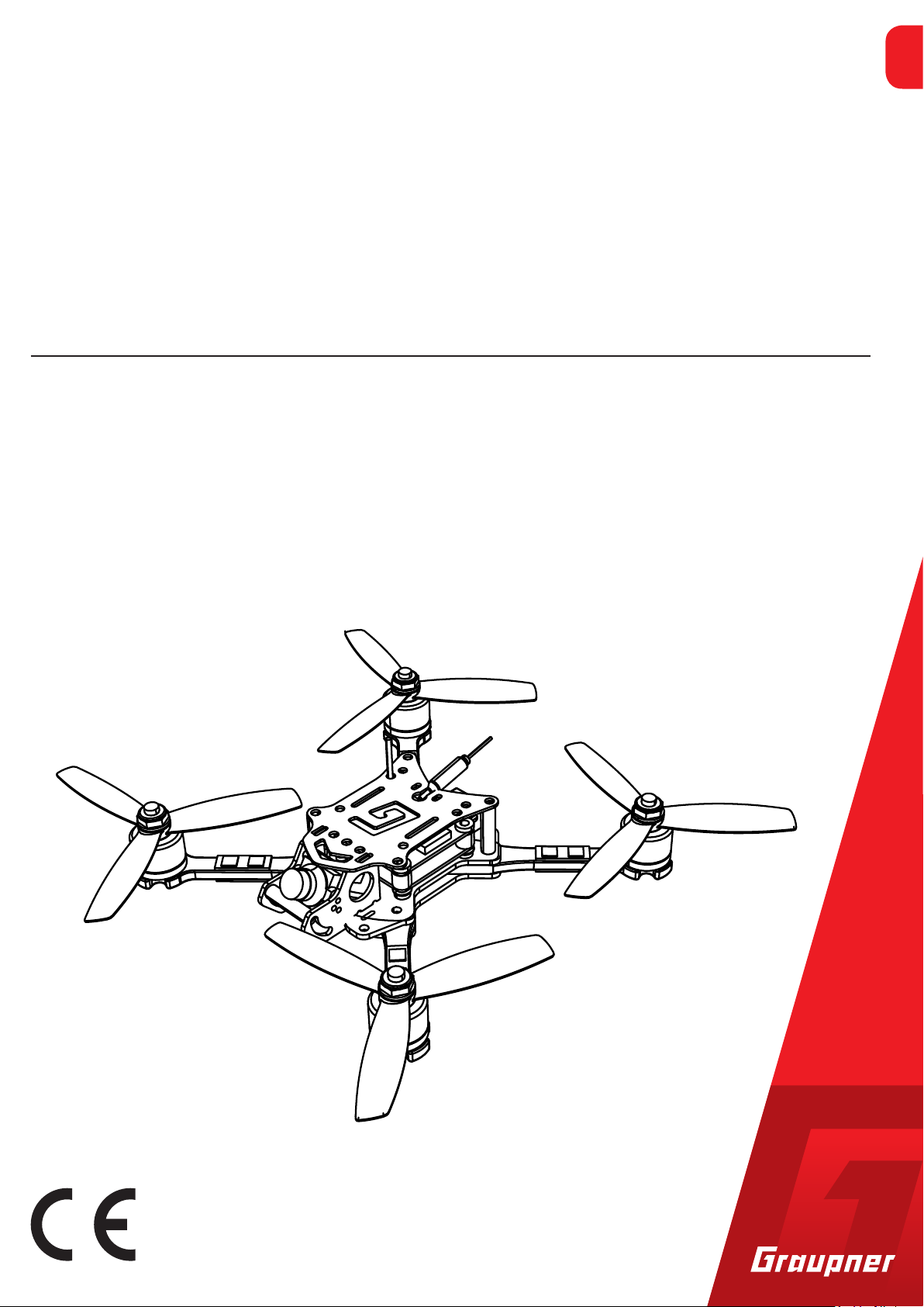
Manual
Alpha 150Q / 170Q / 220Q
Quadcopter
16570.RTF (Racecopter with FPV micro camera and transmitter)
16570.FPV (Racecopter with FPV micro camera)
16570.HoTT (3D copter)
16572.RTF (Racecopter with FPV micro camera and transmitter)
16572.FPV (Racecopter with FPV micro camera)
EN
Copyright © Graupner/SJ GmbH
Page 2

2 / 44
16570.16572_Alpha150Q/170Q /220Q_V1
Page 3

Inhaltsverzeichnis
Introduction ......................................................................................5
Service centre ...................................................................................5
Intended use ....................................................................................6
Package content and technical data ................................................7
16570.RTF .......................................................................................7
16570.FPV .......................................................................................7
16570.HoTT ....................................................................................8
16572.RTF .......................................................................................9
16572.FPV .......................................................................................9
Symbol description .........................................................................12
Safety notes ....................................................................................12
Safety notes for battery ................................................................13
Battery storage..............................................................................13
Charge the LiPo battery ................................................................14
First use ...........................................................................................14
Receiver.........................................................................................14
Installing the LiPo battery in the copter .......................................14
Connecting the LiPo battery .........................................................14
Determining the centre of gravity ................................................14
Default model memory ................................................................15
Binding the receiver .......................................................................16
Range test ........................................................................................17
Flight control ...................................................................................18
MODE 1 .........................................................................................18
MODE 2 .........................................................................................20
MODE 3 .........................................................................................22
MODE 4 .........................................................................................24
Installing the propellers .................................................................26
First flight ........................................................................................26
Camera function .............................................................................27
HoTT transmitter presettings .........................................................27
Control mode ................................................................................28
Flight mode ...................................................................................28
Fail-Safe setting .............................................................................28
Throttle Cut ...................................................................................29
Special functions on channel 6 .....................................................29
"Telemetry" menu ..........................................................................31
SETTING & DATA VIEW ..................................................................31
Receiver display ............................................................................31
ROLL/NICK Display ........................................................................32
16570.16572_Alpha150Q/170Q /220Q_V1
3 / 44
Page 4

YAW Display ...................................................................................33
Multicopter Basis display ..............................................................34
Axis assignment ............................................................................36
Firmware updates ...........................................................................40
SIMPLIFIED DECLARATION OF CONFORMITY ................................42
Notes on environmental protection ..............................................43
Care and maintenance ...................................................................43
Warranty conditions .......................................................................43
4 / 44
16570.16572_Alpha150Q/170Q /220Q_V1
Page 5
Introduction
Thank you very much for purchasing the Graupner 3D or Race cop-
ter Alpha 150Q, Alpha 170Q or Alpha 220Q. These copters are
extremely versatile. This manual is valid for all the copter sets listed
on the cover sheet. The package content changes depending on the
version.
Read this manual carefully to achieve the best results with your
Alpha 150Q, 170Q or 220Q and first of all to safely control your
models. If you experience any trouble during operation, take the
instructions to help or ask your dealer or Graupner Service Centre.
Due to technical changes, the information may be changed in this
manual without prior notice. Be always updated by checking periodically on our website, www.graupner.de to be always uptodate with
the products and firmwares.
This product complies with national and European legal requirements.
To maintain this condition and to ensure safe operation, you must
read and follow this user manual and the safety notes before using
the product!
Service centre
Note
This manual is part of that product. It contains important information concerning operation and handling. Keep these instructions for
future reference and give it to third person in case you gave the
product.
Graupner Central Service
Graupner/SJ GmbH
Henriettenstraße 96
D-73230 Kirchheim/Teck
Servicehotline
(+49) (0)7021/722-130
Monday - Thursday:
9:15 am - 4:00 pm
Friday:
9:15 am - 1:00 pm
service@graupner.de
Graupner USA
3941 Park Dr Suite 20-571
El Dorado Hills, CA 95762
Website: www.graupnerusa.com
Phone: +1 855-572-4746
Email:service@graupnerusa.com
Graupner in Internet For the service centres outside Germany please refer to our web site
www.graupner.de.
16570.16572_Alpha150Q/170Q /220Q_V1
5 / 44
Page 6

Intended use
Target group
The quadcopters Alpha 150Q, 170Q and 220Q are remote controlled quadcopters. Other components are required, depending on
the version, to be able to use one of these copters. Punctual technical information about the components can be found in the Technical
data section.
The quadcopters Alpha 150Q, 170Q or 220Q are designed exclusively to be used as a battery-powered, radio controlled model, any
other use is not allowed. For any improper use no guarantee or liability is assumed.
Read the entire manual in advance before attempting to assemble
and operate one of these copters.
Graupner/SJ constantly works on the development of all products;
we reserve the right to change the item, its technology and equipment.
A quadcopter of the series Alpha 150Q, 170Q or Alpha 220Q is not
a toy. These components are not suitable for children under 14. For
questions about radio-controlled models, please contact an experienced RC model expert or a RC model club.
In addition, it is explicitly pointed out that you must inform yourself
about the laws and regulations applicable at your respective starting
point before starting the remote control operation. Such conditions
may differ from state to state, but this must be followed in every
case. Read through this entire manual before you attempt to install
or use the transmitter.
Note
• After purchase always check the content of the packaging for
integrity or damages.
6 / 44
16570.16572_Alpha150Q/170Q /220Q_V1
Page 7
Package content and technical data
16570.RTF
already assembled Race copter Alpha 170Q
Propellers size 4 x 4,5 inches
Ultra PRO brushless motors 1306
(No. 16570.2300L and No. 16570.2300R)
4in1 ULTRA brushless speed controller BL Heli S (No. S3087)
FPV micro camera V2 (No. 48341)
25 mW 5,8 GHz video transmitter raceband (No. 16570.123)
LiPo battery V-Maxx 3s/850 mAh (No. 78108.3XT30)
Battery charger (No. S2015.XH or 6454.XH)
mz-12PRO HoTT transmitter (No. S1002.PRO77DE)
Assembly material and manual
Recommended accessories
FPV goggle (No. 48354)
Graupner 7“ FPV monitor (No. S8405)
Technical data
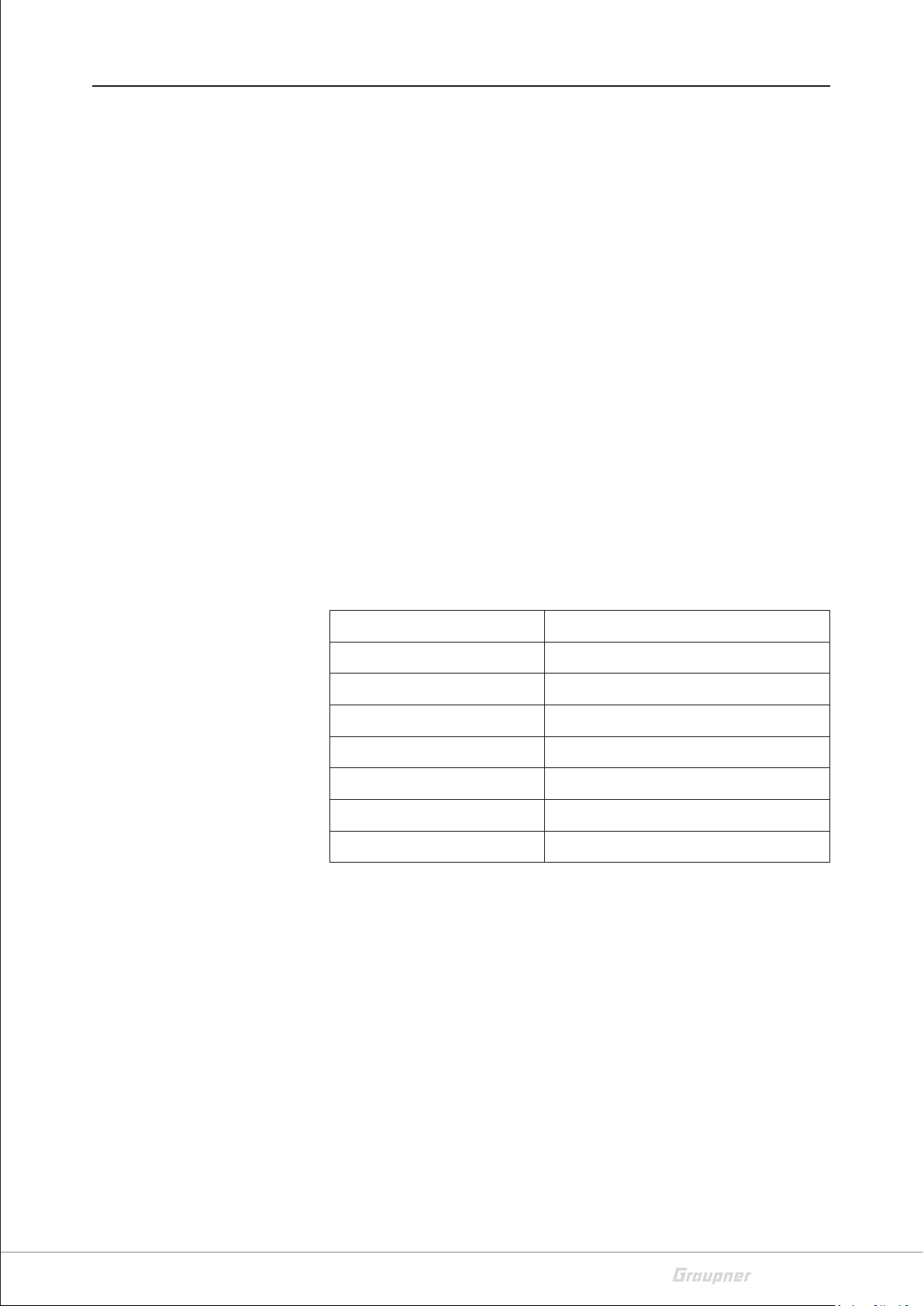
16570.FPV
Length excl. rotors 140 mm
Width excl. rotors 140 mm
Axial distance 122 mm
Propellers 3 blades 4 x 4,5 inches
Chassis material Carbon fibre
Chassis height 30 mm
Weight <250 g w/out battery protection
Video channels in Europe R 3 … 6
already assembled Race copter Alpha 150Q
Propellers size 3 x 5,2 inches
Ultra PRO brushless motors 1306
(No. 16570.3500L and No. 16570.3500R)
Recommended accessories
16570.16572_Alpha150Q/170Q /220Q_V1
4in1 ULTRA brushless speed controller BL Heli S (No. S3087)
FPV micro camera V2 (No. 48341)
25 mW 5,8 GHz video transmitter race band (No. 16570.123)
Assembly material and manual
mz-12PRO HoTT transmitter (No. S1002.PRO77DE)
7 / 44
Page 8
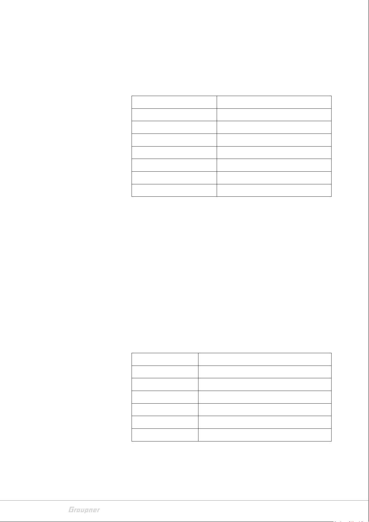
Technical data
16570.HoTT
LiPo battery V-Maxx 3s/850 mAh (No. 78108.3XT30)
Battery charger (No. S2015.XH or 6454.XH)
FPV goggle (No. 48354)
Graupner 7“ FPV monitor (No. S8405)
Length excl. rotors 126 mm
Width excl. rotors 126 mm
Axial distance 106 mm
Propellers 3 blades 3 x 5,2 inches
Chassis material Carbon fibre
Chassis height 30 mm
Weight <250 g w/out battery protection
Video channels in Europe R 3 … 6
Recommended accessories
Technical data
already assembled 3D copter Alpha 170Q
3D propellers size 3,8 x 3,5 inches
Ultra PRO brushless motors 1306
(No. 16570.2300L and No. 16570.2300R)
4in1 ULTRA brushless speed controller BL Heli S (No. S3087)
Assembly material and manual
mz-12PRO HoTT transmitter (No. S1002.PRO77DE)
LiPo battery V-Maxx 3s/850 mAh (No. 78108.3XT30)
Battery charger (No. S2015.XH or 6454.XH)
Length excl. rotors 140 mm
Width excl. rotors 140 mm
Axial distance 122 mm
Propellers 3S 3 blades 3,8 x 3,5 inches
8 / 44
Chassis material Carbon fibre
Chassis height 30 mm
Weight <250 g w/out battery protection
16570.16572_Alpha150Q/170Q /220Q_V1
Page 9
16572.RTF
Recommended accessories
Technical data
already assembled Race copter Alpha 220Q
Propellers size 5 x 4,6 inches
Ultra PRO brushless motors 2206 (No. S7118 + S7119)
4in1 ULTRA brushless speed controller BL Heli S (No. S3088)
FPV micro camera V2 (No. 48341)
25 mW 5,8 GHz video transmitter raceband (No. 16570.123)
LiPo battery V-Maxx 3s/1300 mAh (No. 78113.3)
Battery charger (No. S2015.XH or 6454.XH)
mz-12PRO HoTT transmitter (No. S1002.PRO77DE)
Assembly material and manual
LiPo V-Maxx 4s/1800 mAh (No. 78118.4FPV)
FPV goggle (No. 48354)
Graupner 7“ FPV monitor (No. S8405)
16572.FPV
Length excl. rotors 185 mm
Width excl. rotors 185 mm
Axial distance 156 mm
Propellers 3 blades 5 x 4,6 inches
Chassis material Carbon fibre
Chassis height 30 mm
Weight <500 g
Video channels in Europe R 3 … 6
already assembled Race copter Alpha 220Q
Propellers size 5 x 4,6 inches
Ultra PRO brushless motors 2206 (No. S7118 + S7119)
4in1 ULTRA brushless speed controller BL Heli S (No. S3088)
FPV micro camera V2 (No. 48341)
25 mW 5,8 GHz video transmitter raceband (No. 16570.123)
Recommended accessories
16570.16572_Alpha150Q/170Q /220Q_V1
Assembly material and manual
mz-12PRO HoTT transmitter (No. S1002.PRO77DE)
LiPo battery V-Maxx 4s/1800 mAh (No. 78118.4FPV)
Battery charger Ultramat 14 plus (No. 6464)
FPV goggle (No. 48354)
9 / 44
Page 10
Technical data
Graupner 7“ FPV monitor (No. S8405)
Length excl. rotors 185 mm
Width excl. rotors 185 mm
Axial distance 156 mm
Propellers 3 blades 5 x 4,6 inches
Chassis material Carbon fibre
Chassis height 30 mm
Weight <500 g
Video channels in Europe R 3 … 6
10 / 44
16570.16572_Alpha150Q/170Q /220Q_V1
Page 11

16570.16572_Alpha150Q/170Q /220Q_V1
11 / 44
Page 12

Symbol description
!
!
Safety notes
Always observe the information indicated by these warning signs.
Particularly those which are additionally marked with the words
CAUTION or WARNING.
The signal word WARNING indicates the potential for serious injury,
the signal word CAUTION indicates possibility of lighter injuries.
The signal word Note indicates potential malfunctions.
Attention indicates potential damages to objects.
This safety notes are intended to protect you and other people. They
are also used for safe handling the product. Therefore please read
this section very carefully before using the product!
• Do not leave the packaging material lying around, this could be
a dangerous toy for children.
• Persons, including children, with reduced physical, sensory or
mental capabilities, or lack of experience or knowledge, or not
capable to assemble and use safely one of these 3D or Race
copter Alpha 150Q, 170Q or Alpha 220Q must not use it without supervision or instruction by a responsible person.
• Operation and use of radio-controlled models needs to be
learnt! If you have never operated a model of this type before,
start carefully and make yourself familiar with the model's
reactions to the remote control commands. Proceed responsibly.
• First, always perform a range and function test on the ground
according to the manual of your transmitter (to do so, hold
your model tight), before you use your model. Repeat the test
with running motor and with short throttle bursts.
• Due to safety and licensing reasons (CE), any unauthorized
reconstruction and/or modification of the product is prohibited.
• Only use the components and spare parts that we recommend.
Always use matching, original Graupner plug-in connections of
the same design and material.
• Make sure that all of the plug-in connections are tight. When
disconnecting the plug-in connections, do not pull the cables.
12 / 44
16570.16572_Alpha150Q/170Q /220Q_V1
Page 13

• Protect your copter from dust, dirty, humidity and other small
!
!
parts. Do not expose it to vibrations or to extreme heath or
cold. The models may only be operated remotely in normal
outside temperatures such as from -10°C to +55°C.
• Always use all your Graupner HoTT components only with the
latest firmware version.
• If you have questions which cannot be answered by the operating manual, please contact us (contact information see page
5) or another expert in the field.
WARNING
• During programming, make sure that connected electric motors
do not start unintentionally. Injury risk by the turning propellers! For safety reasons always remove the propellers when
programming. Always activate the Motor Stop function according to the instructions of your transmitter.
• Avoid impacts and crushing. Check the copter regularly for
damages to the housings and cables, specially after model
crashes. Damaged or wet electronic components, even if
re-dried, should no longer be used!
Safety notes for battery
• Never touch the turning propellers, this can cause serious
injury.
• The propellers must be mounted securely, thrown parts can
cause serious injury.
• Never stay in the danger area of running propellers! Long hair,
loose clothing such as scarves, loose shirts or similar, can be
sucked in by the propeller, flying parts can lead to serious injuries.
• Observe the safety notes of the required components.
CAUTION
• LiPo batteries are not a toy. Persons, including children, with
reduced physical, sensory or mental capabilities, or lack of
experience or knowledge, or not capable to use safely the battery must not use the battery without supervision or instruction by a responsible person.
16570.16572_Alpha150Q/170Q /220Q_V1
13 / 44
Page 14

Battery storage
• Any alterations to the battery, charger or charging cables can
cause serious injury. Risk of fire and explosions! Risk of burns!
• Do not use any damaged battery or charger, risk of short-circuit
and fire!
LiPo batteries should be stored with a voltage of about 3,8V per cell.
If the cell voltage falls below 3 V, then the battery must be necessarily charged. Deep discharge and storage in discharge status (cell voltage < 3V) make the battery useless. For transport and storage the
LiPo batteries should be placed in a safety bag e.g. No. 8373.
Notes
• Remove the battery from the model when transporting or when
not in use.
• During transport protect the model and the transmitter from
damages.
Charge the LiPo battery
First use
Receiver
Connect the LiPo battery to the supplied charger and charge it as
described in the corresponding manual.
The following optional components may be required to commission
the copter:
Remote control HoTT transmitter (mz-12 Pro or higher) and a matching charger.
For versions 16570.RTF, 16570.FPV and 16572.RTF and 16572.FPV,
optionally available video goggle (No. 48354) or an optionally available FPV monitor (No. S8405) are needed for the FPV flight.
The integrated HoTT receiver is optimally matched to the respective
copter at the factory. To program some parameters, refer to the section "Receiver settings".
Installing the LiPo battery in the copter
To compensate for the weight of the camera, place the LiPo battery
slightly backwards with a self-adhesive Velcro strip on the underside
14 / 44
16570.16572_Alpha150Q/170Q /220Q_V1
Page 15
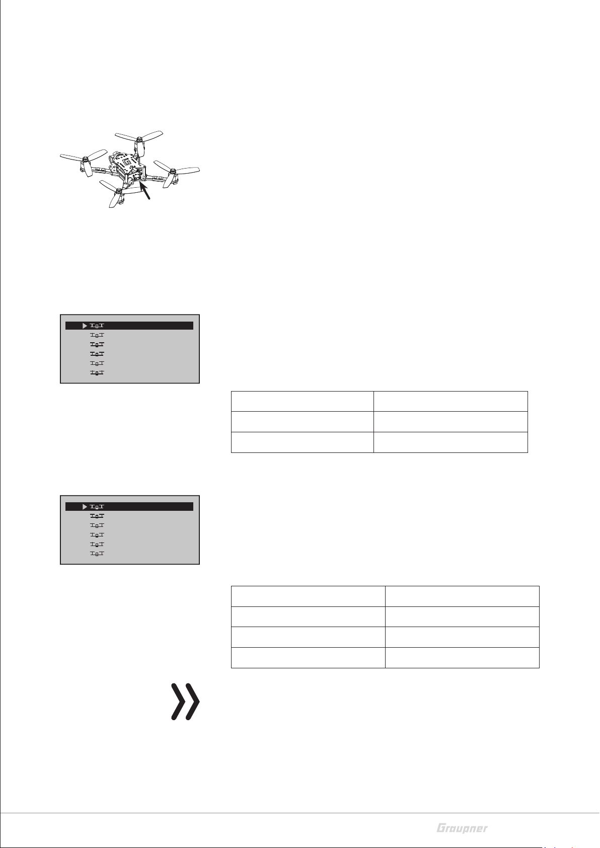
Connecting the LiPo battery
Default model memory
of the frame and, after fine-tuning the centre of gravity, secure it
against falling with an additional Velcro strip.
To start up the copter, plug the connector of the main battery into
the corresponding socket on the back of the copter and remove it
again after setting the flight mode.
Determining the centre of gravity
Hold the copter in the middle of the upper frame with two fingers
and lift it up. The copter should take a horizontal position. Otherwise, move the battery accordingly.
04
05
06
07
08
09 Alpha 1703D
01
02
03
04
05
06 VersaCopt
Hornet250
Xcell 220
VersaCopt
Alpha 150
Alpha 170
Alpha 110
Alpha 150
Hornet250
Alpha 300
Xcell 220
–––
–––
• The kits 16570.RTF and 16572.RTF are delivered with the transmitter Graupner mz-12 Pro HoTT.
In accordance with the type of copter included in the set, the
supplied transmitter is already linked to a preprogrammed model
memory in both cases.
No. / Copter model Suitable sample memory
16570.RTF / Alpha 170Q Alpha 170 (Alpha 110)
16572.RTF / Alpha 220Q Alpha 170 (Alpha 110)
• The kits 16570.FPV, 16570.HoTT and 16572.FPV are delivered
without HoTT transmitter.
The optional Graupner mz-12 Pro HoTT transmitter already contains preprogrammed pattern memory. More are available for
download on the respective product page at www.graupner.de.
With the help of the option „Model memory“ of the PC program
„Firmware_Upgrade_gr_studio“ these sample programs can be
transferred to the transmitter.
No. / Copter model Suitable sample memory
16570.16572_Alpha150Q/170Q /220Q_V1
16570.FPV / Alpha 150Q Alpha 150 (Alpha 110)
16570.HoTT / Alpha 170Q 3D Alpha 1703D (Alpha 300)
16572.FPV / Alpha 220Q Alpha 110 / 150 / 170
Note
In both cases, it is recommended not to use the pre-programmed
model memory directly, but to copy it into a free model memory in
accordance with the transmitter manual and then rename it accordingly.
15 / 44
Page 16

Binding the receiver
Depending on the scope of delivery of your set, the receiver integrated in your 3D or Race copter Alpha 150Q, 170Q or Race copter
Alpha 220Q may already be bound to the transmitter Graupner
mz-12 Pro HoTT included in the set.
If you want to bind the copter to another transmitter or renew a
binding, proceed as follows:
Binding step-by-step
1. Switch on transmitter.
2. Start the copter by plugging in the drive battery.
On the left side of the copter, the status LED lights up red for
about 15 seconds: The copter waits exclusively for control signals
from "its" transmitter.
3. After the expiration of these approx. 15 seconds, the status LED
starts flashing rhythmically red: The receiver of the copter is now
in bind mode.
‖ If "his" previous HoTT transmitter is switched on, the existing
binding is retained.
‖ If a binding process is triggered on another HoTT transmitter
according to its description, the receiver of the copter binds
to this transmitter and the existing binding is lost.
4. If the binding process was successful, the red status LED on the
copter goes out and the green LEDs that may be present on the
arms of the copter light up constantly. Otherwise the process has
to be repeated.
Attention
As mentioned above, the receiver of a 3D or Race copter Alpha
150Q, 170Q and Race copter Alpha 220Q is in binding mode approx-
imately 15 seconds after the battery is plugged in. If the copter is
already bound to a specific transmitter and should this binding be
maintained, the transmitter must therefore be switched on for
safety reasons before the commissioning of the copter or at the latest within this period of 15 seconds. Otherwise, there is an acute
danger that the copter unintentionally binds to a foreigner Graupner
HoTT transmitter, which is eventually in binding mode at the same
time, and consequently goes into uncontrolled operation.
16 / 44
16570.16572_Alpha150Q/170Q /220Q_V1
Page 17

Range test
Carry out the range test of a Graupner HoTT remote control system
according to the instructions in your transmitter manual. It is useful
to have an assistant who helps you.
Attention
Never start a range test on the transmitter during normal model
operation!
16570.16572_Alpha150Q/170Q /220Q_V1
17 / 44
Page 18
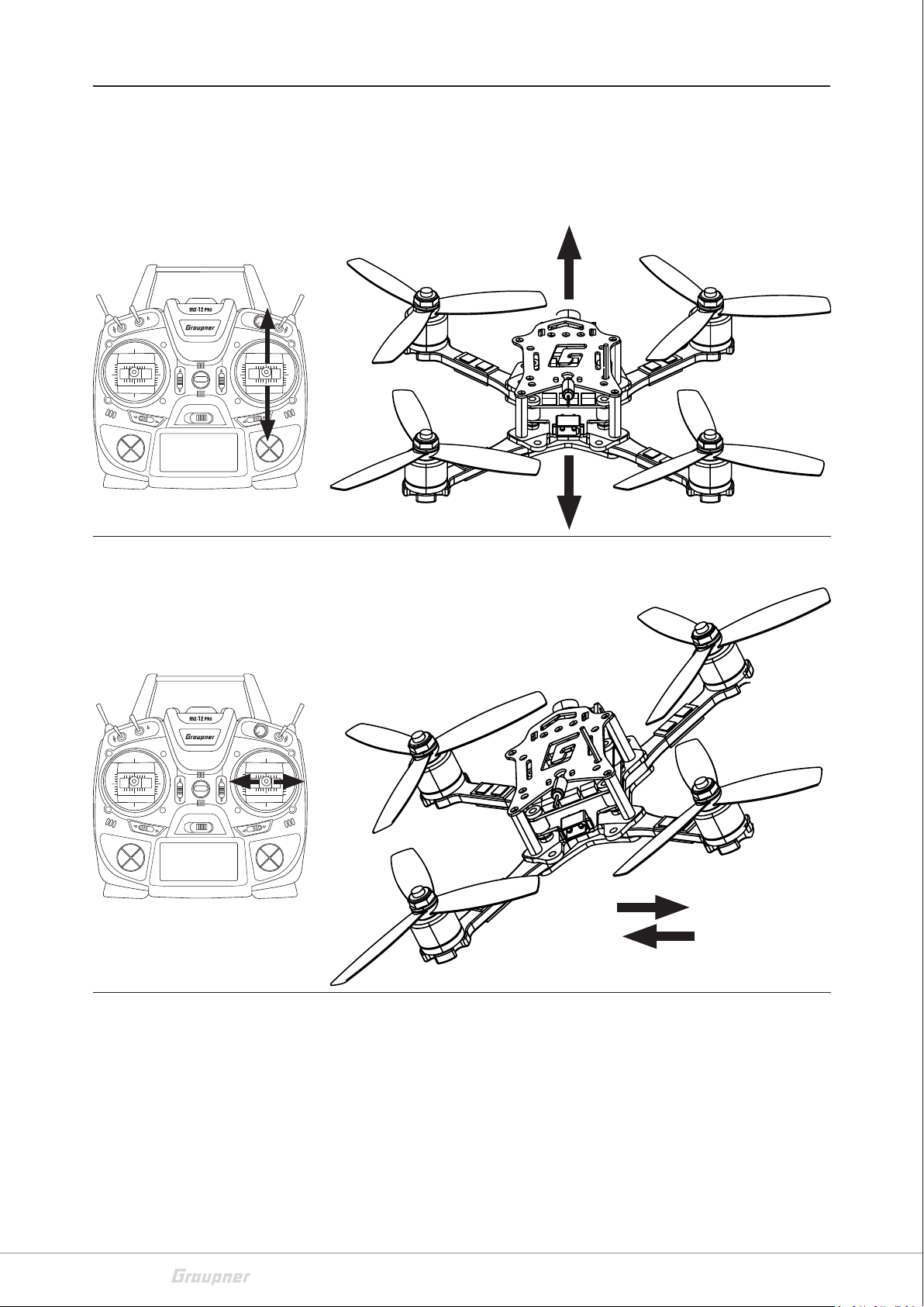
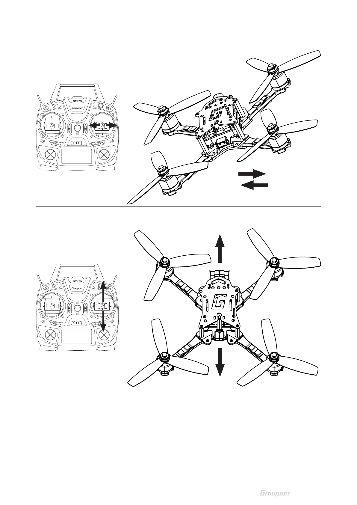
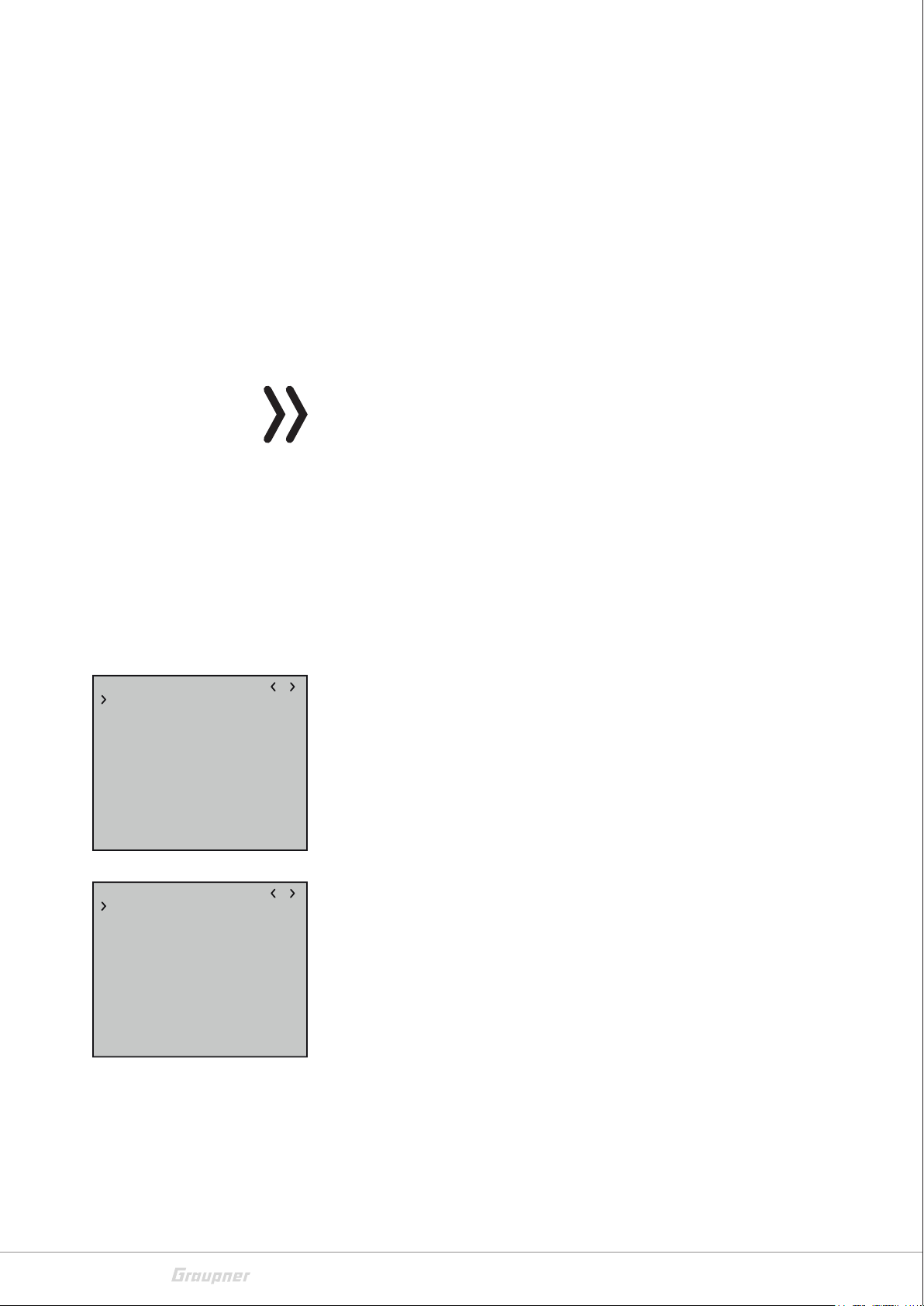
Flight control
MODE 1
Climb and sink
Roll to the right and left
18 / 44
16570.16572_Alpha150Q/170Q /220Q_V1
Page 19

Turn (yaw)
Forward and backward (nick)
v
16570.16572_Alpha150Q/170Q /220Q_V1
19 / 44
Page 20

MODE 2
Climb and sink
Turn (yaw)
20 / 44
16570.16572_Alpha150Q/170Q /220Q_V1
Page 21
Roll to the right and left
Forward and backward (nick)
16570.16572_Alpha150Q/170Q /220Q_V1
21 / 44
Page 22

MODE 3
Climb and sink
Turn (yaw)
22 / 44
16570.16572_Alpha150Q/170Q /220Q_V1
Page 23

Roll to the right and left
Forward and backward (nick)
v
16570.16572_Alpha150Q/170Q /220Q_V1
23 / 44
Page 24

MODE 4
Climb and sink
Roll to the right and left
24 / 44
16570.16572_Alpha150Q/170Q /220Q_V1
Page 25

Turn (yaw)
Forward and backward (nick)
16570.16572_Alpha150Q/170Q /220Q_V1
25 / 44
Page 26

Installing the propellers
!
1R
2L
CAUTION
Risk of injury by rotating propellers in case the motors start.
Always unplug the connector to the battery before working on
the propellers.
Install the propellers as shown in the picture on the left. Be sure to
attach the right propeller to each motor. The propellers are marked
accordingly. If only one propeller is put on wrong, the copter is not
able to fly.
On the two, seen from above, running counterclockwise motors left
front (1) and right rear (3) you have to install the propellers marked
with an "R".
4L
First flight
3R
On the two, seen from above, clockwise running motors right front
(2) and left rear (4) you have to install the propellers marked with an
"L".
Another orientation option is: The outer propeller blades of the two
front propellers must be directed obliquely backwards at the top and
the two rear propellers diagonally forward at the top.
For the first flight, select a large, free flight surface with not too hard
ground. At least initially always start, fly and land in attitude mode
because the copter is easier to control. Familiarize yourself with the
flight behaviour of your copter before you switch to the Rate mode
for the first time. Proceed carefully and responsibly.
Commissioning the copter step-by-step
1. Switch on transmitter.
2. Activate the Motor Stop function by switching the corresponding
switch.
26 / 44
3. Start the copter by plugging in the battery.
‖ After commissioning of the copter, its position stabilization is
immediately active, but not yet initialized.
4. Place the copter horizontally on a suitable surface for about 3 sec
after switching on.
‖ The calibration process can only be performed when the
receiver is absolutely still. Always wait until the calibration
process has finished before starting to fly the model.
16570.16572_Alpha150Q/170Q /220Q_V1
Page 27

‖ If required, you can achieve the same effect with a corre-
spondingly long-lasting stopover on a suitable surface.
5. Move the throttle / pitch control stick to idle position.
This is usually the "back" end point.
6. Deactivate the Motor Stop function.
The propellers start to rotate at low speed.
7. Carefully move the throttle / pitch stick forward until the copter
is about one meter high and hold it at that height.
‖ Initially, move the control sticks slightly so that you have
enough time to familiarize yourself with the copter's reactions.
‖ If, especially when hovering, the copter always drifts in a cer-
tain direction, compensate the movement by tapping the corresponding trim button in the opposite direction. Alternatively, you can land and move the battery in the opposite
direction.
Camera function
8. After landing, first activate the motor stop function, then first put
the transmitter away and take the copter in hand to stake out the
battery.
With the exception of the 3D copter included in the set No. 16570.
HoTT, all other copter models have a factory-ready built-in micro-camera and a video transmitter. The transmission of the camera image
begins with the connection of a battery to the copter. Then, if necessary, scan the transmission channel of the copter on the video
goggle or on the video monitor.
The copter-side video channel switching is described in the next section under "Special functions on channel 6".
To align the camera unscrew the fixing screws of the red spacer and
loosen the camera; the spacer is then to move appropriately to align
the camera as desired. Finally, tighten all four screws again.
For sharpness adjustment loosen the ribbed ring on the camera
optics; turn this accordingly and finally secure the position found by
tightening the knurled ring again.
16570.16572_Alpha150Q/170Q /220Q_V1
27 / 44
Page 28

HoTT transmitter presettings
Depending on the bandwidth of the model type selection of the
HoTT transmitter used, either the model type "Copter" or alternatively a "Fixed-wing model" should be selected. Some of the current
HoTT transmitters are even shipped with preconfigured model memory, such as: for example, the transmitter mz-12 Pro HoTT included
in some sets. The following programming suggestions and display
illustrations are also based on this transmitter.
Control mode
According to the transmitter instructions, the appropriate control
mode and, if necessary, "motor front / rear" must be set. Usually
"backwards" so that the channel 1 indicator in the servo display indicates -100% in the "motor off" position of the "throttle / pitch control
stick".
Flight mode
Flight mode has to be set to channel 5. To do this, program a 2-way
switch in the "Control settings" menu on Channel 5 as follows:
I5
free
I6
I7 +100%
free
I8 +100%
I9 +100%
1
3
–100%
5
7
9
11
+
I5
free
I6
I7 +100%
free
I8 +100%
I9 +100%
1
3
+100%
5
7
9
11
+
3
0%
0%
0%
0%
0%
3
0%
0%
0%
0%
0%
+100%
+100%
10
12
+100%
+100%
10
12
• Attitude mode
+100%
+100%
+100%
+100%free
+100%free
trv
+
The stick movements act directly proportionally to Roll and Nick.
In the attitude mode, the maximum inclination angle is limited to
approx. 50° at 100% of the stick travel.
The attitude mode is active as long as the bar of channel 5 is on
the left of -50% in the »Servo display«. How far to the left is irrelevant.
2
4
6
8
+
+100%
+100%
+100%
+100%free
+100%free
trv
0%
0%
0%
0%
0%
0%
+
(The -100% shown on the left are based on the switch programming above.)
Flight mode suggested for beginners.
• Rate mode
In this mode, the rate is determined by the rash of the stick without inclination limit. In this aerobatic mode rolls and loops are
possible.
The Rate mode is active as soon as the bar of channel 5 is to the
right of +50% in the display "Servo display". How far to the right
is irrelevant.
2
4
6
8
0%
0%
0%
0%
0%
0%
+
(The -100% shown on the left are based on the switch programming above.)
Not suitable for beginners.
28 / 44
16570.16572_Alpha150Q/170Q /220Q_V1
Page 29

Fail-Safe setting
FAIL SAFE
Pos
Hold
1 2 3
Delay 0.25s STO
5
4
6
Throttle Cut
Mod.Name
Control mode
Motor on C1
M Stop
Timers 0:00 –––
ALPHA 110
–125% +100%
7 8
1
Idle B.
1
We recommend to set Channel 1 and Channel 5 to "Pos" according
to the transmitter instructions and, before saving the fail-safe settings, set the throttle / pitch control stick to the motor OFF position
and the Attitude / Rate mode switch to the "OFF" position Position
"Rate mode" to be active in fail-safe situations:
In such a case, a red LED will flash on the left side of the Alpha 150Q,
170Q or Alpha 220Q quadcopter. The motors run with the minimum
power set in the "MINPOWER%" line of the "Multicopter Basis" display described later and the position control of the copter is still
active.
This state continues until a correct transmitter signal is recognized
again by the receiver module.
For safety reasons, a motor stop switch must always be programmed
on the transmitter side according to the transmitter instructions.
Only when this is placed into the appropriate position, an undesired
start of the motors is reliably prevented.
Motor stop in Acro 3D mode
M1
M2
M3
M4
M5
MIX 1
trv +100%+100%
offs
STO
–100%
1
3
–100%
5
7
9
11
+
type
0%
0%
0%
0%
S
??
??
??
??
fro
+100%
SEL
S 5
2
4
6
8
10
12
5
??
??
??
??
to
+
1
=
0%
0%
0%
0%
0%
0%
When operating the copter in Acro 3D mode with the Rate mode
enabled, the motor stop function of the transmitter will not shut off
the motors, but set them to "full power backwards". To prevent this,
a mixer is to be programmed in such a way that switching the motor
stop switch to the motor OFF position also automatically switches
over to the position mode in which the stop of all motors is then
ensured.
Programming step-by-step
1. Program a linear mixer of "S => 5" according to the transmitter
instructions.
2. Give this mixer the same switch with the same switching direction
that activates the motor stop function.
Keep this switch in the motor OFF position while programming
the mixer.
3. Change to the setting page of the mixer.
4. Set the "travel" symmetrically to +100%.
5. Change to the line "Offset".
6. Now manually set the offset value to +100%, so as shown in the
picture on the left, see middle illustration on the left.
And in the servo display, the bars of channels 1 and 5 should be
set to -100% despite the Rate mode is activated, see the lower
figure on the left.
16570.16572_Alpha150Q/170Q /220Q_V1
29 / 44
Page 30

Special functions on channel 6
Through the channel 6 of the transmitter it is possible to switch up
to three special functions, but the auto-flip function additionally
requires a mixer.
• Video channel switching
I5
SW6/7
I6
I7 +100%
free
I8 +100%
I9 +100%
+100%
3
+100%
+100%
+100%
+100%
+100%free
+100%free
trv
There are four video channels available in Europe. Between them
is switched in rotation process, each with a short control pulse of
+100% to the control channel 6. In parallel, the colour of the LED
lighting of the copters changes.
+
• red = Video channel R3
• green = Video channel R4
• blue = Video channel R5
• white = Video channel R6
To toggle the video channels as well as the lighting of the copter,
in the menu "Control setting", program one of the self-resetting
switches on your transmitter to "input 6" and leave the rest at
their default values.
In the preprogrammed model memory "Alpha 110" of the optionally supplied transmitter mz-12 Pro HoTT is the right front
mounted switch "S6". From this three-stage switch, only the
self-resetting switch function is used.
• Auto-Flip
With the auto-flip function, it is easy to perform a flip in the Attitude mode with the copter.
M1
M2
M3
M4
M5
L.MIX1
trv
os
Typ
–125%
S
??
??
??
??
fro
0%
However, since the auto-flip function should only be activated in
"Attitude mode", the corresponding dependency is established
by setting a free mixer of "5 => 6" as follows:
Programming step-by-step
6
2
–––
??
–––
??
??
–––
??
–––
zu
6
5
0%
ASYSYM
1. Select "5" in the "from" column of a free linear mixer.
2. In the now accessible column "to",select "6" as target.
3. In the column above the switch symbol assign a self-resetting
switch, for example the switch 2 of the mz-12 Pro HoTT.
4. Change to the setting side of the mixer and hold down the
button just assigned to set the mixer.
5. According to the transmitter description, an asymmetrical
path of at least -110% has to be set. However, as shown in the
figure, a setting between -125% and -150% is recommended.
6. Recall the servo display for checking:
30 / 44
16570.16572_Alpha150Q/170Q /220Q_V1
Page 31

"Telemetry" menu
Copter Alpha 220Q
Copter Alpha 150Q/170Q
SETTING & DATA VIEW
ശ In Attitude mode, when the selected switch is activated,
the channel 6 bar must exceed the minimum value of
+110%.
ശ In the Rate mode, the bar of channel 6 must remain at 0%
even if the selected switch is pressed.
So programmed, the auto-flip function can be "armed" in the
Attitude mode with a short change of the self-resetting switch for
about 5 seconds. As soon as the roll or pitch control stick is moved
more than 50% of its way within this time, the copter will automatically flip to the appropriate direction.
Note
After the flip, position deviations in the range of <10 ° are possible.
Telemetry
SETTING & DATA VIEW
SENSOR
RF STATUS VIEW
VOICE TRIGGER
RX DATA ON
ALARM SETTING
Receiver display
RECEIVER Q.06
LANGUAGE: English
ALARM VOLT: 10.2V
ALARM TEMP: 70°C
VIDEO CHANNEL R3
ALARM CAPAC. 600mAh
K5: SERVO
RECEIVER Q.06
LANGUAGE: English
ALARM VOLT: 10.2V
ALARM TEMP: 70°C
VIDEO CHANNEL R3
ALARM CAPAC. 1200mAh
K5: SERVO
The basic handling of the "Telemetry" menu is described in the manual of the respective HoTT transmitter with display. By way of derogation, only in certain receivers the menu structure is summarized
under the generic term "setting & data view". These instructions
also provide information on how to access this menu. Change accordingly to the first setting page of the receiver module of the 3D or
Race copter Alpha 150Q, 170Q or Race copter Alpha 220Q.
Note
The setting values shown in the following display illustrations show
the respective default values of the copters mentioned above.
LANGUAGE
In the "Language" line you can set the display language in the receiver
menu.
The choices are: German, English, French, Italian, Spanish
ALARM VOLT
If the receiver voltage falls below the set value, a low-voltage warning is generated by the transmitter in the form of a "sound-declining
16570.16572_Alpha150Q/170Q /220Q_V1
31 / 44
Page 32
alarm tone" or the "receiver voltage" speech output message.
Copter Alpha 150Q/170Q
3D Copter Alpha 170Q
ALARM TEMP
If the receiver temperature exceeds the set temperature, a warning
is generated by the transmitter in the form of a "3-step sound-climbing alarm tone" or the "receiver temperature" speech output message.
The adjustment range is 5 ° increments from 50 to 80 °C.
Video channel
If necessary, select the desired video channel in this line. Their selection depends on the region and its regulations.
Note
As described under "Special functions on channel 6" described
above, it is possible to change in rotation between the available
video channels through a push button.
ALARM CAPACITY
In this line, to be on the safe side, select a value that is approximately
10 to 15% lower than the nominal capacity of the battery used, so
that enough time and power remain for a safe landing.
ROLL/NICK Display
MULTICOPTER RO/NI
ROLL/NICK P 40
ROLL/NICK D 40
DAMPING 9
ROLL FACTOR % 95
POWER2SENS. 100
R/N DYNAMIC 70
––ATTITUDE MODE––
ROLL/NICK I 40
AGILITY 8
––RATE MODE––
R/N RATE I 17
RATE 70
MULTICOPTER RO/NI
ROLL/NICK P 30
ROLL/NICK D 40
DAMPING 30
ROLL FACTOR % 95
POWER2SENS. 80
R/N DYNAMIC 70
––ATTITUDE MODE––
ROLL/NICK I 40
AGILITY 8
––RATE MODE––
R/N RATE I 15
RATE 70
The control is based on the PID principle, where the "P" stands for
"proportional", the "I" for "integral" and the "D" for "digital". In short
...
... the deviation from the setpoint proportional to the manipulated
variable has an effect at the P value.
... the existing control deviation is continuously summed up at the I
value and then acts on the manipulated variable via the I value.
... the differential component only takes into account the speed of
the control deviation and then acts on the control accordingly via the
D component.
ROLL/NICK P
This parameter determines the tilting behaviour of the copter during
the maximum climb.
In order to prevent tilting at full climbing power in the end, this
parameter must be increased in steps of 5 until a medium-fast tilting
occurs. Subsequently, this value is to be adjusted in individual steps
until the tilting has disappeared.
32 / 44
16570.16572_Alpha150Q/170Q /220Q_V1
Page 33

MULTICOPTER RO/NI
Race Copter Alpha 220Q
ROLL/NICK P 25
ROLL/NICK D 35
DAMPING 30
ROLL FACTOR % 95
POWER2SENS. 100
R/N DYNAMIC 70
––ATTITUDE MODE––
ROLL/NICK I 40
AGILITY 8
––RATE MODE––
R/N RATE I 15
RATE 70
ROLL/NICK D
This parameter determines the tilting behaviour of the roll / pitch
function of the copter.
As described above, this parameter must be adjusted until the Multicopter engages exactly over Roll and Nick. A too high value leads to
very rapid oscillations.
DAMPING
The damping factor should be set as low as possible, but as high as
necessary, so that the PID control can operate optimally. If you do
not get vibrations away with the PID settings , then change the damping of 1 step and test whether the setting works better or worse.
ROLL FACTOR %
Set the Roll setting as percent value of the overall gain. For symmetrical copters, the value should normally be left at 100. If, because of
its gravity centre, the Copter is more agile on the Roll axis than on
the Nick axis, then you can change here the roll factor.
POWER 2SENS.
This parameter allows you to set a kind of gyro suppression. Higher
values result in an increased suppression towards full throttle.
R/N DYNAMIC
Higher dynamic values provide a more direct feel for the flight (3D
flight 50 ... 100), lower dynamic values for smoother flight recordings, rounder freestyle flying and races (30 ... 50).
Adjustment range: MIN (deactivated), 1 …100, (0)C5, (50)C6 … (50)
C16
Alternatively, the effect on the R/N Dynamic value can also be
adjusted by the transmitter. To do this, a rotary or slider control is
assigned to one of the control channels 5 ... 16 and the remaining
settings are left at the default values. In the value field of the "R/N
Dynamic" line, the corresponding channel is then merely to be
selected instead of a fixed value.
Note
If a channel is selected in the "R / N DYNAMIC" line, but no encoder
is assigned to it on the transmitter side, the value in brackets is
specified.
–– ATTITUDE MODE ––
16570.16572_Alpha150Q/170Q /220Q_V1
ROLL/NICK I
Set the I component of the Attitude mode. At too low values of Copter tilts slowly.
33 / 44
Page 34

–– Rate mode ––
Copter Alpha 150Q/170Q
3D Copter Alpha 170Q
YAW Display
If it stops after a roll or pitch command and “oscillates”, the value
must be reduced.
AGILITY
This value determines how fast a change of position is made.
R/N RATE I
Sets the I component of the rotation in rate mode. At too low values
of Copter tilts slowly. If it stops after a roll or pitch command and
“oscillates”, the value must be reduced.
RATE
This value sets the maximum potential rate in Rate mode.
The general comments on PID control in the description of the roll /
pitch display are also applicable here.
MULTICOPTER GIER
YAW P 40
YAW I 12
YAW D 10
RATE 70
YAW DYNAMIC 75
Race Copter Alpha 220Q
MULTICOPTER YAW
YAW P 25
YAW I 12
YAW D 10
RATE 70
YAW DYNAMIC 75
YAW P
The P factor is responsible for the snap to yaw. Higher values result
in a faster stop. At too high P-values the copter starts to “swing”. In
such cases, the value must be reduced again.
YAW I
The I-factor ensures constant rotations. Start with low values and
only increase them until the rotations are constant. Too high value
cause an oscillation when you stop. Eventually, the motors can start
rotating and thus cause unwanted rising.
YAW D
The D-factor affects the stopping behaviour in Yaw. Normally a hard
D action is necessary. The D component must be set as low as possible, since it affects the whole system.
RATE
For beginners a rate value of approx. 50, for racers and freestyle
pilots between 50 and 70 are recommended.
34 / 44
16570.16572_Alpha150Q/170Q /220Q_V1
Page 35
Multicopter Basis display
Copter Alpha 150Q/170Q
Race Copter Alpha 220Q
3D Copter Alpha 170Q
MULTICOPTER BASIC
TYPE QUADRO XI
ESC S3087
MODE NORMAL
MINPOWER % 10
FREESTYLE 1
CALIBR.POSITION NO
KALIBR.LAGE NEIN
MULTICOPTER BASIC
TYPE QUADRO XI
ESC S3088
MODE NORMAL
MINPOWER % 5
FREESTYLE 1
CALIBR.POSITION NO
KALIBR.LAGE NEIN
YAW DYNAMIC
Higher dynamic values provide a more direct feel for the flight (3D
flight 80 ... 100), lower dynamic values for smoother flight recordings, rounder freestyle flying and races (30 ... 80).
TYPE
The "Type" line defines the basic configuration of the copter. The fol-
lowing selections are available: "Quadro X", "Quadro XI" and "Quadro
+". The default setting "Quadro XI" is, however, to be maintained,
otherwise the copter will become uncontrollable.
ESC
This term is composed of the first letters of the English term "Electronic Speed Control" as a synonym for "motor control". In this line,
therefore, the type of the installed motor control must be entered
de facto. This value is, like the previous "type", given by the facto-
ry-installed technique of the copter and therefore may not be
changed at will.
MODE
MULTICOPTER BASIC
TYPE QUADRO XI
ESC S3087
MODE ACRO 3D
MINPOWER % 15
FREESTYLE 1
CALIBR.POSITION NO
KALIBR.LAGE NEIN
NORMAL
This setting must be used for copters with speed controller without
reverse of the direction of rotation.
ACRO 3D
This setting is reserved for copters whose speed controllers are
equipped with direction reverse.
Attention
The setting ACRO 3D is reserved for the 3D copter Alpha 170Q No.
16570.HoTT.
Note
For safety reason the "Type" and "Mode" changes take effect after
switching off and on the receiver system.
16570.16572_Alpha150Q/170Q /220Q_V1
35 / 44
Page 36

!
positive full throttle
negative full throttle
linear to full throttle
linear
MINIPOWER %
Travel Throle/Pitch control sck
idle
linear
CAUTION
• Since after changing to ACRO 3D the power control in Rate
mode is different, as shown in the figure on the left, the motors,
depending on the current position of the throttle / pitch control stick, can change more or less when switching from the
Attitude mode to the Rate mode or Acro 3D mode. Therefore
always mount the propellers immediately before starting the
flight operation and start and land exclusively in "attitude
mode".
motor idle
• During prolonged extreme aerobatics of the copter in Acro 3D
mode (e.g. , sequence> 1min), the receiver may lose its attitude information and, as a result, the copter may move to an
undesired position when switching to attitude mode. In this
situation, the copter should be in the Rate mode and either it
is left quiet for about 30 seconds or it is landed for a short time,
so that the receiver can readjust the position information
again.
MINPOWER %
If the throttle / pitch control stick is moved past its stop on the idleside stopper of the copter speed controller, the motors will start to
run. The setting value of this option determines the minimum power
to be provided at the switch-on point so that the position control can
continue to operate in the Attitude mode and it can also serve as a
rescue mode in an emergency. But do not set a too high value here
in order not to restrict too much the control range of the speed controller.
The adjustment range is 5 ... 35%.
FREESTYLE
36 / 44
The setting basically serves to prevent the I-factor from generating
a vibration.
The higher the value, the more I-vibrations are prevented, but also
the straight-ahead flight is degraded. Values up to max. 20 recommended.
Adjustment range: MIN (deactivated), 1 …100, (0)C5, (50)C6 … (50)
C16
Alternatively, the effect on the I value can also be adjusted by the
transmitter. To do this, a rotary or slider control is assigned to one of
the control channels 5 ... 16 and the remaining settings are left at the
default values. In the value field of the "Freestyle" line, the corresponding channel is then merely to be selected instead of a fixed
value.
Note
If a channel is selected in the "FREESTYLE" line, but no encoder is
assigned to it on the transmitter side, the value in brackets is specified.
16570.16572_Alpha150Q/170Q /220Q_V1
Page 37

Axis assignment
CALIBR.POSITION
With this option, if necessary, the basic calibration of the acceleration sensors can be readjusted, so that the copter hovers with the
control stick and trim to neutral, in attitude mode, precisely horizontally.
To recalibrate, place the copter on an absolutely horizontal surface
and then set the value field to "YES".
As soon as the calibration is completed, the display changes back to
"NO". To accept the calibration that has just been carried out in the
non-volatile memory of the receiver, it is essential to push or tap on
the ENT key.
Note
The gyroscope calibration, required each time the copter is switched
on, takes place as soon as the copter or its receiver is absolutely
quiet. The motors will not start until the calibration is completed.
AXIS ASSIGNMENT
DO SETUP No
ROLL +2
NICK +1
YAW –3
In this display, the gyros and their effective direction can be determined. A readjustment is normally not necessary with the quadcopter Alpha 150Q, 170Q or Alpha 220Q.
DO SETUP
After selecting the line "do setup" and changing the value field to
"yes", assign the axes as follows:
Do setup step by step
1. Push or tap on the ENT key
"NO" is displayed inverted.
2. Change the value field to "YES".
3. Push or tap on the ENT key
4. At the transmitter briefly bring the roll control stick to the right
stop.
The display shows the roll axis inverted.
5. Tilt the copter more than 45 degrees to the right.
As soon as the detected axis with the required sign is displayed in
"normal" representation, the axis assignation is completed.
16570.16572_Alpha150Q/170Q /220Q_V1
6. At the transmitter briefly bring the nick control stick to the front
stop.
The display shows the nick axis inverted.
7. Tilt the copter more than 45 degrees to the front.
As soon as the detected axis with the required sign is displayed in
"normal" representation, the axis assignation is completed.
37 / 44
Page 38

8. At the transmitter briefly bring the yaw control stick to the right
stop.
9. Turn the copter clockwise by more than 45 degrees to the right.
As soon as the detected axis with the required sign is displayed in
"normal" representation, the axis assignation is completed.
The gyros and their operating directions have now been assigned.
Attention
To be on the safe side, the directions of action of the gyroscope settings must be checked.
Check step by step
1. Remove the rotors of the copter.
2. Use the pitch control stick to give approx. 25% "throttle".
All motors run at the same speed.
3. Switch to the attitude mode.
4. Tilt the copter forward.
The front motors must turn faster than back ones.
5. Tilt the copter to one side.
The motors of the side, the "hanging" side must turn faster than
those of the opposite, higher side.
‖ If this is not the case, the entire gyro assignment must be
repeated.
38 / 44
16570.16572_Alpha150Q/170Q /220Q_V1
Page 39

16570.16572_Alpha150Q/170Q /220Q_V1
39 / 44
Page 40

Firmware updates
The required programs and files are enclosed in a software pack and
can be found for the corresponding product at www.graupner.de.
Download this software package from the Internet, and unpack it on
your Windows PC or laptop.
The procedure is also described in detail in the manual contained in
the data package. You can also singularly download these from the
download page of the product at www.graupner.de.
Notes
• Please note that compatible firmware is required for reliable
communication between the HoTT components. The programs
and files that are required for updates are therefore combined
into a single pack that is currently named "HoTT_Software_
V4.zip".
• Always use all your RC components only with the latest firmware version. The current firmware version can be found on the
Internet at www.graupner.de.
Firmware updates of a 3D or Race Copter Alpha 150Q, 170Q or
Alpha 220Q are performed via the connector on the left side of the
copter using a laptop or PC running Windows 7 ... 10. You will need
the optionally available USB interface, No. 7168.6, as well as the
adapter cables No. 7168.S and S1038.2.
Connect the adapter lead to the USB interface. The polarity of the
plug-in system cannot be reversed. Note the small chamfers on the
sides. Do not use force, the plug should click into place easily. Finally,
connect the adapter cable S1038.2 with the correct polarity to the
corresponding end of the adapter cable 7168.S.
Now push the narrow white plug all the way into the side connector.
But do not apply force.
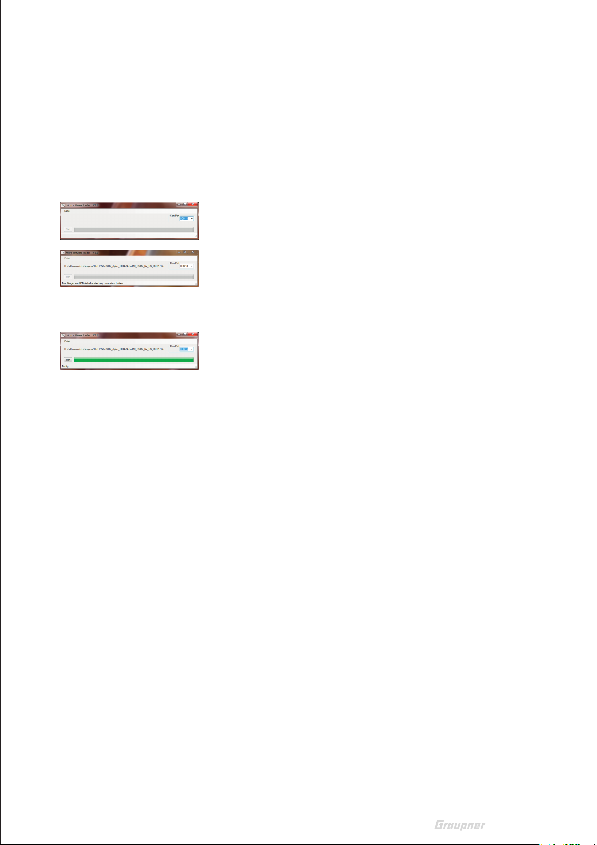
The update takes place via the program part "Slowflyer / Gyro
Receiver Downloader" of the program "Firmware_Upgrade_gr_Studio" available under "Links". Please follow the notes of the software.
Firmware update step-by-step
1. Download the required firmware file from the product page to
your PC and unzip it if necessary.
2. Be sure to check the charge level of the battery to be used as the
power source before each firmware update.
3. When switched off, connect the device to be powered up to a PC
or laptop using the aforementioned cables and adapters.
40 / 44
16570.16572_Alpha150Q/170Q /220Q_V1
Page 41
ശ Do not interrupt this connection during an update! Therefore,
it is essential to ensure trouble-free contact between transmitter and computer, and later, after plugging in the power
source, between copter and power source.
4. Start the program "Firmware_Upgrade_gr_Studio".
5. Select the correct COM port in the program part "Port select" of
the "Firmware_Upgrade_gr_Studio".
6. Open the program part "Slowflyer, Gyro Receiver Downloader" of
the "Firmware_Upgrade_gr_Studio".
7. Click on "File" in the upper left corner and change to the location
of the previously downloaded upgrade file in the following "Open
File" dialog.
8. Select the ".bin" file matching your copter.
9. Click on "Start".
10. Now connect the battery, previously checked for its charge status,
to the copter.
The firmware upgrade process starts.
11. The end of the data transfer will be indicated by the update program.
12. Disconnect the battery from the copter and then disconnect the
PC or laptop.
13. Be sure to check the copter for correctness after each update.
16570.16572_Alpha150Q/170Q /220Q_V1
41 / 44
Page 42

SIMPLIFIED DECLARATION OF CONFORMITY
Graupner/SJ hereby declares that the radio systems 16570.RTF,
16570.FPV, 16570.HoTT, 16572.RTF and 16572.FPV comply with
Directive 2014/53/EU.
The full text of the EU Declaration of Conformity is available at the
following Internet address: www.graupner.de.
42 / 44
16570.16572_Alpha150Q/170Q /220Q_V1
Page 43

Notes on environmental protection
P
If this symbol is on the product, instructions for use or packaging, it
indicates that the product may not be disposed with normal household waste once it has reached the end of its service life. It must be
turned over to a recycling collection point for electric and electronic
apparatus.
Individual markings indicate which materials can be recycled. You
make an important contribution to protection of the environment by
utilizing facilities for reuse, material recycling or other means of
exploiting obsolete equipment.
Batteries must be removed from the unit and disposed of separately
at an appropriate collection point. Please inquire if necessary from
the local authority for the appropriate disposal site.
Care and maintenance
The product does not need any maintenance. Always protect it
against dust, dirt and moisture.
Clean the product only with a dry cloth (do not use detergent!) lightly
rub.
Warranty conditions
Graupner/SJ GmbH, Henriettenstrassee 96, 73230 Kirchheim/Teck
grants from the date of purchase of this product for a period of 24
months. The warranty applies only to the material or operational
defects already existing when you purchased the item. Damage due
to misuse, wear, overloading, incorrect accessories or improper handling are excluded from the guarantee. The legal rights and claims
are not affected by this guarantee. Please check exactly defects
before a claim or send the product, because we have to ask you to
pay shipping costs if the item is free from defects.
These operating instruction are exclusively for information purposes
and are subject to change without prior notification. The current
version can be found on the Internet at www.graupner.de on the
relevant product page. In addition, the company Graupner/SJ has
no responsibility or liability for any errors or inaccuracies that may
appear in construction or operation manuals.
Not liable for printing errors.
16570.16572_Alpha150Q/170Q /220Q_V1
43 / 44
Page 44

 Loading...