

Page 1
GRAUPNER/SJ GmbH D-73230 KIRCHHEIM/TECK GERMANY
Änderungen vorbehalten! Keine Haftung für Druckfehler! 08/2014
1
No. 9929.HOTT
MONTAGEANLEITUNG
HoTT BADGER
RC-Fast-Fertigflugmodell ausgestattet mit Brushless-Antrieb
Zur Steuerung wird ein HoTT COMPUTERSYSTEM benötigt
Page 2
GRAUPNER/SJ GmbH D-73230 KIRCHHEIM/TECK GERMANY
Änderungen vorbehalten! Keine Haftung für Druckfehler! 08/2014
2
Bitte unbedingt die speziellen Sicherheitshinweise innerhalb der Montageanleitung und diese
im Anhang beachten. Sofern das Modell an eine andere Person weitergegeben wird, muss die
komplette Montageanleitung zur Beachtung weitergegeben werden.
Allgemeines
Der Graupner HoTT BADGER ist ein besonders attraktiver RC-Trainer mit
hochqualitativer Serienausstattung. Für die Modellmontage wird kein Klebstoff
benötigt, die Modellteile wie z.B. Seiten- und Höhenleitwerk werden lediglich
eingeschoben und magnetisch gehalten. Besonders hervorzuheben ist auch, dass im
Bausatz ein Sport-Tragflächenpaar sowie die notwendigen Montagewerkzeuge
enthalten sind. Bitte lesen Sie dringend vor der Inbetriebnahme des Modells diese
Montageanleitung vollständig durch.
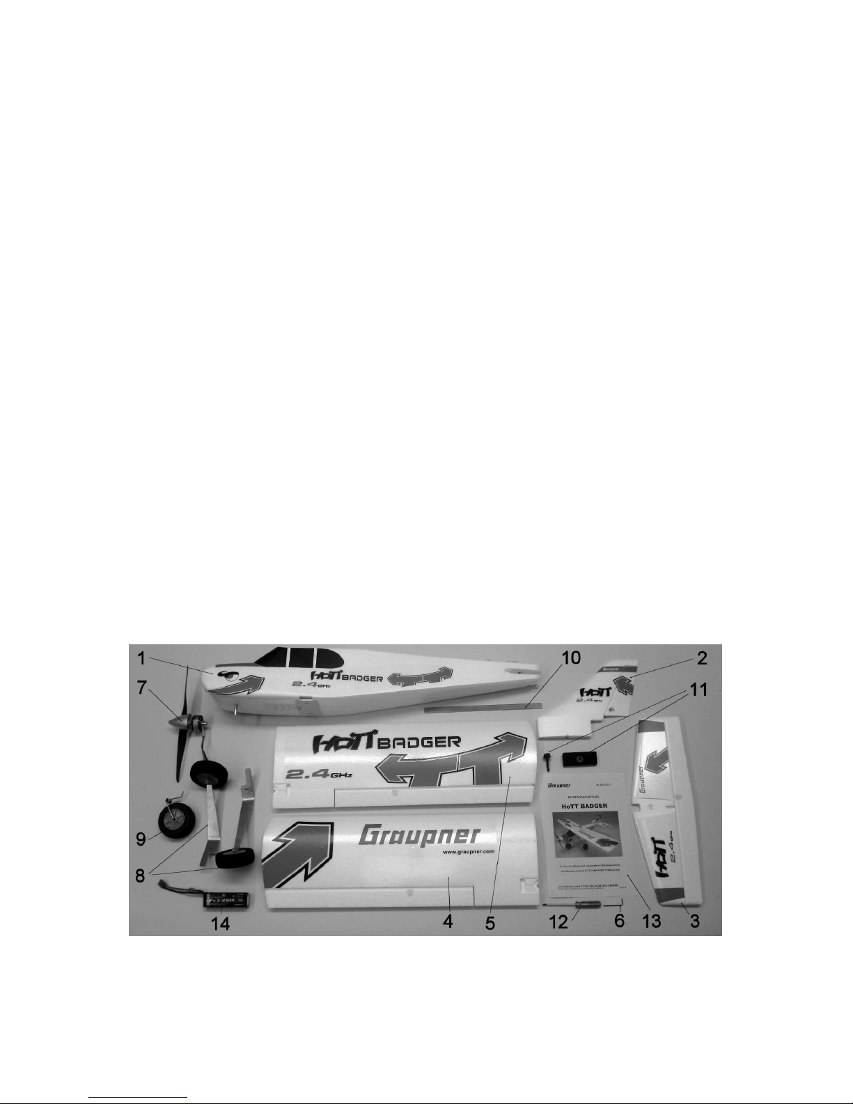
Packungsinhalt
1. Fertigrumpf mit Ruderanlenkungen und abnehmbarer Motorhaube. BRUSHLESS
CONTROL +T 35 G3,5 No.33735 . Empfänger GR-12+3xGHoTT Gyro No. 33576,
2 Stück Servos DES 488 BB MG 12 mm No. 7919 betriebsfertig installiert.
2. Seitenleitwerk mit montiertem Ruderhorn.
3. Höhenleitwerk mit montiertem Ruderhorn.
4. Linke Tragflächenhälfte mit Querruderservo DES 488 BB MG 12 mm No. 7919.
5. Rechte Tragflächenhälfte mit Querruderservo DES 488 BB MG 12 mm No. 7919
6. Sechskant-Stiftschlüssel SW 1,5 mm.
7. BRUSHLESS Motor AT 3511-750 KV mit Luftschraube und Spinner.
8. Hauptfahrwerk, 1 Paar.
9. Bugfahrwerk
10. Tragflächenverbinder
11. Tragflächen-Befestigungselemente
12. Kreuzschlitz Schraubendreher
13. Montageanleitung mit Sicherheitshinweisen in Deutsch, Englisch und
Französisch.
14. LiPo-Akku 20C 3/2500 11,1V No. 7633.3
Die Abbildung zeigt die für die Standardversion erforderlichen Einzelteile, für die
Sport-Version sind zusätzliche Teile enthalten.
Page 3
GRAUPNER/SJ GmbH D-73230 KIRCHHEIM/TECK GERMANY
Änderungen vorbehalten! Keine Haftung für Druckfehler! 08/2014
3
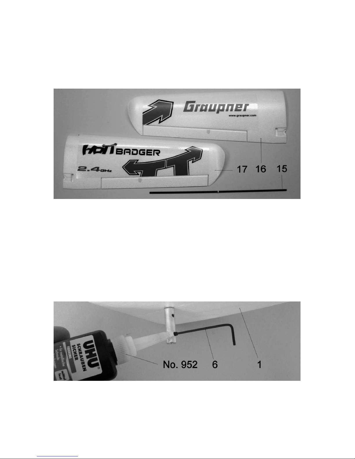
Zusätzlicher Packungsinhalt
15. Tragflächenverbinder für Sport-Tragflächenpaar
16. Linke Sport-Tragflächenhälfte (ohne Querruderservo, ohne Ruderanlenkung.
17. Rechte Sport-Tragflächenhälfte (ohne Querruderservo, ohne Ruderanlenkung.
Weiterhin enthalten, jedoch nicht abgebildet, Bedienungsanleitungen zu Empfänger
und Drehzahlregler sowie Sicherheitshinweise zu LiPo-Akku.
Die Abbildung zeigt die Einzelteile für die Tragflächen der Sport-Version.
Erforderliches Zubehör (nicht enthalten)
Graupner MX-12 Computersystem HoTT No. 33112
LiPo Ladegerät QUICK 70 No. 64070
Ladekabel G 3,5 No. 2970.L
UHU Schraubensicherung No. 952
Die Modellmontage
Das Modell ist nach wenigen Montageschritten flugbereit, die nachfolgenden
Hinweise sind jedoch genau zu beachten, damit ein sicherer Betrieb gewährleistet ist.
Montieren Sie zuerst das Fahrwerk. Bringen Sie dann das Seiten- und
Höhenruderservo per Servotester oder Fernsteuerung in ihre Mittelstellung.
Achtung: Die Befestigungsschraube für das Bugfahrwerk (9) unbedingt mit
UHU-Schraubensicherung sichern und darauf achten, dass die Abflachung des
Page 4
GRAUPNER/SJ GmbH D-73230 KIRCHHEIM/TECK GERMANY
Änderungen vorbehalten! Keine Haftung für Druckfehler! 08/2014
4
Fahrwerkdrahtes (9) mit der Befestigungsschraube übereinstimmt. Die
Befestigungsschraube fest anziehen.
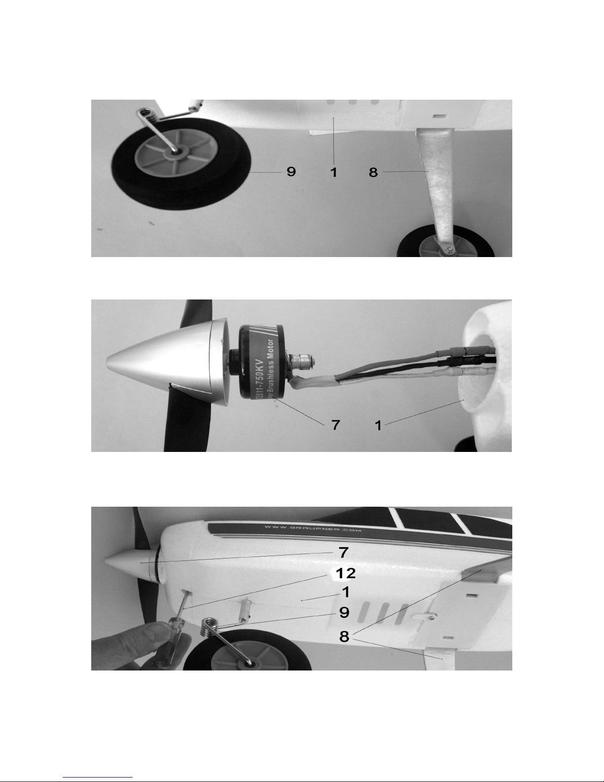
Die Abbildung zeigt das fertig montierte Bugfahrwerk (9) und das eingeschobene
Hauptfahrwerk (8). Die abgeschrägte Seite der Hauptfahrwerksbügel liegt vorne.
Die Abbildung zeigt den angeschlossenen Motor (7) unbedingt darauf achten, dass
die Kabelfarben übereinstimmen und die Steckverbindungen vollständig geschlossen
sind. Jetzt den Motor einschieben.
Die Abbildung zeigt das Festziehen der Motorbefestigungsschraube, bitte dringend
nachfolgende Hinweise beachten. Achtung: Zuerst die Befestigungsschraube für
Page 5
GRAUPNER/SJ GmbH D-73230 KIRCHHEIM/TECK GERMANY
Änderungen vorbehalten! Keine Haftung für Druckfehler! 08/2014
5
den Motor (7) mit dem Kreuzschlitzschraubendreher (14) herausschrauben und
UHU-Schraubensicherung auftragen, darauf achten, dass die Schraube dann
fest angezogen wird. Hinweis: Die Motorhaube kann nötigenfalls für die Arbeiten
am Antrieb nach vorne abgezogen werden, da sie mit Magnetverschlüssen
ausgestattet ist.
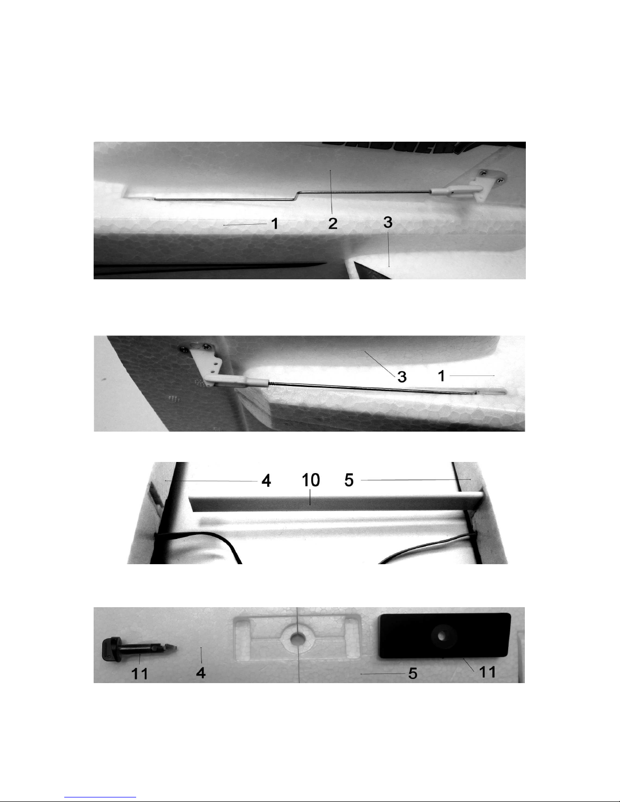
Die Abbildung zeigt das eingeschobene Höhen- und Seitenleitwerk. Wenn beide
Leitwerksteile vollständig eingeschoben sind die Gabelköpfe wie gezeigt in die
Ruderhörner einhängen.
Die Abbildung zeigt das richtig eingehängte Höhenrudergestänge.
Die Abbildung zeigt das Zusammenschieben der beiden Tragflächenhälften mit
Verbinder (10). Achtung: Keinesfalls Klebstoff dafür verwenden.
Mit dem Einlegen der Verbindungsplatte (11) ist der Tragflächenaufbau bereits
abgeschlossen. Die Tragfläche probeweise mit Stift (11) auf den Rumpf setzen.
Page 6
GRAUPNER/SJ GmbH D-73230 KIRCHHEIM/TECK GERMANY
Änderungen vorbehalten! Keine Haftung für Druckfehler! 08/2014
6
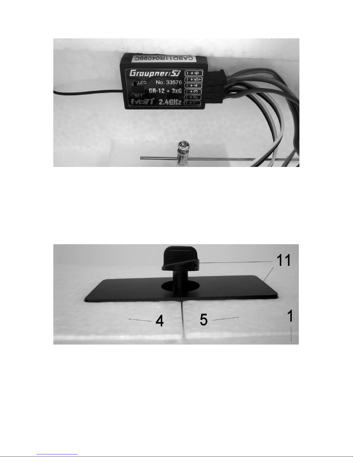
Die Abbildung zeigt den serienmäßig installierten GR-12+3xG HoTT-Empfänger.
Achtung: Die Empfängerposition keinesfalls verändern und darauf achten,
dass der Empfänger sicher und fest mit dem Rumpf verbunden ist. Ist dies
nicht der Fall ist die selbststabilisierende Gyrofunktion nicht gewährleistet. Die
Längsachse des Empfängergehäuses muss mit Längsachse des Modells
übereinstimmen. Den Empfänger nun an den Sender binden. Die
Querruderservokabel mit dem bereits im Empfänger eingeschobenen V-Kabel
einstecken. Darauf achten, dass die Stecker vollständig eingeschoben sind. Für den
ersten Funktionstest die Tragfläche mit Stift (11) auf dem Rumpf befestigen.
Die Abbildung zeigt das korrekte Verriegeln der Tragfläche mit den
Befestigungselementen (11) in der Ansicht von hinten. Den Stift in dieser Position
eindrücken, bis er einrastet, dann um 90° nach links drehen.
Achtung: Vor jedem Start mit einem Belastungstest prüfen ob die Tragfläche
fest verriegelt ist. Wird dies nicht beachtet kann sich die Tragfläche während
des Fluges vom Rumpf lösen, was unweigerlich zu einem Absturz führt,
denken Sie daran, dass Sie damit sich selbst oder andere Personen im
schlimmsten Fall lebensgefährlich verletzen können.
Page 7
GRAUPNER/SJ GmbH D-73230 KIRCHHEIM/TECK GERMANY
Änderungen vorbehalten! Keine Haftung für Druckfehler! 08/2014
7
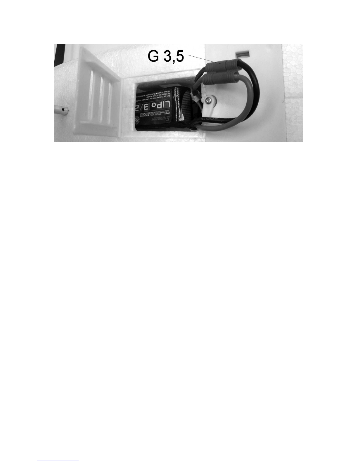
Die Abbildung zeigt die auf der Rumpfunterseite eingeschobene LiPo-Batterie mit
geschlossener G 3,5 Steckverbindung. Das Kabel komplett in den Akkuraum
einschieben und die Kunststoffklappe schließen und verriegeln.
Denken Sie daran, dass mit dem Schließen der G 3,5-Steckverbindung, wie auf
der Abbildung zu sehen, der Empfänger eingeschaltet ist. In diesem Zustand
kann der Motor durch unvorhersehbare Umstände plötzlich anlaufen, es
besteht hohe Verletzungsgefahr. Deswegen, nach dem Schließen der G 3,5Steckverbindung die Luftschraube keinesfalls berühren und von allen
Gegenständen freihalten.
Die Ruderausschläge
Die Ruderausschläge sind werkseitig für ca. 100% Servoweg richtig eingestellt und
haben nachfolgende Werte, jeweils gemessen an der Ruderendkante und an der
Ruderinnenseite: Seitenruder ca. 25 mm, Höhenruder ca. 10 mm nach oben und
unten, Querruder ca. 10 mm nach oben und unten.
Extra Zubehör Sport-Tragfläche
Wenn Sie die ersten Flugerfahrungen mit dem HoTT BADGER gemacht haben
können Sie das Modell mit der beiliegenden Sport Tragfläche tunen. Das Modell fliegt
damit schneller und ist wesentlich agiler, die Kunstflugeigenschaften verbessern sich
damit. Bitte beachten Sie, dass sowohl die Querruderservos als auch die
Anlenkungen dazu nicht enthalten sind und von der Standard-Tragfläche abmontiert
werden müssen. Das Prinzip der Tragflächenbefestigung und der Belastungsprobe
vor jedem Start bleibt unverändert.
Der Schwerpunktbereich
Der Schwerpunktbereich des HoTT BADGER liegt zwischen 60 und 70 mm, von der
Tragflächenvorderkante aus gemessen. Sofern die empfohlene LiPo-Batterie
verwendet wird, liegt der Schwerpunkt automatisch in diesem Bereich. Die
Schwerpunktlage kann zur Kontrolle geprüft werden, indem das Modell im
Schwerpunktbereich unterhalb der Tragfläche unterstützt wird. Das Modell soll
waagrecht auspendeln.
Hinweis: Wenn der Schwerpunkt bei 60 mm liegt muss das Höhenruder ca. 3 mm
nach oben getrimmt werden.
Page 8

GRAUPNER/SJ GmbH D-73230 KIRCHHEIM/TECK GERMANY
Änderungen vorbehalten! Keine Haftung für Druckfehler! 08/2014
8
Der Erstflug
Laden Sie zuerst die LiPo- und die Senderbatterie voll. Verwenden Sie dazu
ausschließlich die von uns empfohlenen Ladegeräte und beachten Sie die
Bedienungsanleitung und Sicherheitshinweise der Ladegeräte.
Das fertig vorbereitete Modell bei schwachem Wind einfliegen, das Modell per
Bodenstart gegen die Windrichtung starten.
Eine Trimmung des Modells insbesondere nach dem ersten Start ist unerlässlich, sie
erfolgt über die Trimmtasten unterhalb bzw. neben den Steuerknüppeln. Das Modell
mit dem Trimmtaster für das Querruder so austrimmen, dass es geradeaus fliegt. Die
Landung exakt gegen die Windrichtung mit abgeschaltetem Antrieb durchführen. Vor
dem Aufsetzen die Fluggeschwindigkeit des Modells durch dosierte
Höhenruderausschläge reduzieren. Die Landung immer gegen die Windrichtung
ausführen.
Bitte beachten Sie, dass die G 3,5-Steckverbindung nach jedem Betrieb des
Motors bzw. des Modells aus Sicherheitsgründen und zum Schutz der LiPoBatterie unbedingt wieder getrennt werden muss.
GRAUPNER Modellbau wünscht Ihnen viele schöne Flüge mit dem neuen
Flugmodell
HoTT BADGER
Technische Daten
Spannweite ca. 1280 mm
Länge ü.a. ca. 940mm
Tragflächeninhalt ca. 28,0 dm²
Höhenleitwerksinhalt ca. 5,8 dm²
Gesamtflächeninhalt ca. 33,8 dm²
Gesamtflächenbelastung ca. 35,5 g/ dm²
Fluggewicht ca. 1200 g
Ersatzteile (nicht enthalten)
No. Bezeichnung
9929.4 HOTT Höhen-und Seitenleitwerk
9929.5 Hauptfahrwerk
9929.12 Luftschraube
9929.16 Spinner
9929.26 Bugfahrwerk
9929.40 Tragflächen-Befestigungselemente
9929.81 Brushless Motor komplett mit Luftschraube und
Spinner
33735 BRUSHLESS CONTROL +T 35 G3,5
7919.LOSE Ersatz-Servo
9929.200 HOTT Fertigrumpf mit 2 Servos und HoTT-Empfänger
9929.300 HOTT Tragflächenpaar mit Servos
9929.301 HOTT Sport-Tragflächenpaar
7633.3 LiPo-Akku 20C 3/2500 11,1V
Page 9
GRAUPNER/SJ GmbH D-73230 KIRCHHEIM/TECK GERMANY
Änderungen vorbehalten! Keine Haftung für Druckfehler! 08/2014
9
Hinweise zum Umweltschutz
Das Symbol auf dem Produkt, der Gebrauchsanleitung oder der Verpackung weist darauf hin, dass dieses Produkt am Ende
seiner Lebensdauer nicht über den normalen Haushaltsabfall entsorgt werden darf. Es muss an einem
Sammelpunkt für das Recycling von elektrischen und elektronischen Geräten abgegeben werden.
Die Werkstoffe sind gemäß ihrer Kennzeichnung wiederverwertbar. Mit der Wiederverwendung, der stofflichen
Verwertung oder anderen Formen der Verwertung von Altgeräten leisten Sie einen wichtigen Beitrag zum
Umweltschutz.
Batterien und Akkus müssen aus dem Gerät entfernt werden und bei einer entsprechenden Sammelstelle getrennt entsorgt
werden.
Bitte erkundigen Sie sich bei der Gemeindeverwaltung die zuständige Entsorgungsstelle.
Sicherheitshinweise
Für den Betrieb Ihres Flugmodells benötigen Sie eine gültige Haftpflichtversicherung, dies ist
vom Gesetzgeber so vorgeschrieben.
Vor dem Versuch der ersten Inbetriebnahme muss die gesamte Betriebsanleitung sorgfältig
gelesen werden. Sie alleine sind verantwortlich für den sicheren Betrieb Ihres RC-Flugmodells.
Bei Jugendlichen muss der Betrieb von einem Erwachsenen, der mit den Gegebenheiten und
möglichen Gefahren eines RC-Flugmodells vertraut ist, verantwortlich überwacht werden.
Rechtlich gesehen ist ein Flugmodell ein Luftfahrzeug und unterliegt entsprechenden
Gesetzen, die unbedingt eingehalten werden müssen. Es dürfen nur die in der Packung
enthaltenen Teile, sowie die ausdrücklich von uns empfohlenen Original-Graupner-Zubehörund Ersatzteile verwendet werden. Wird eine Komponente der Antriebseinheit geändert, ist ein
sicherer Betrieb nicht mehr gewährleistet und es erlischt jeglicher Garantieanspruch.
Kurzschlüsse und Falschpolungen vermeiden.
Durch die hohe Energie der Batterien besteht Explosions- und Brandgefahr.
Nur ein vorsichtiger und überlegter Umgang beim Betrieb schützt vor Personen- und
Sachschäden. Niemand würde sich in ein Segelflugzeug setzen und - ohne vorausgegangene
Schulung - versuchen, damit zu fliegen. Erfolgreiches Modellfliegen erfordert ebenso eine
Ausbildungs- bzw. Übungsphase.
Der Hersteller hat jedoch keine Möglichkeit, den Bau und den Betrieb eines RC-Flugmodells zu
beeinflussen. Deshalb wird hiermit auf die Gefahren nachdrücklich hingewiesen und jede
Haftung dafür abgelehnt.
Bitte wenden Sie sich dazu an erfahrene Modellflieger, an Vereine oder Modellflugschulen.
Ferner sei auf den Fachhandel und die einschlägige Fachpresse verwiesen. Am besten als
Club-Mitglied auf zugelassenem Modellflugplatz fliegen.
Der Betreiber muss im Besitz seiner vollen körperlichen und geistigen Fähigkeiten sein. Wie
beim Autofahren, ist der Betrieb des Flugmodells unter Alkohol oder Drogeneinwirkung nicht
erlaubt.
Informieren Sie Passanten und Zuschauer vor der Inbetriebnahme über Gefahren, die von
Ihrem Modell ausgehen und ermahnen Sie diese, sich in ausreichendem Schutzabstand
aufzuhalten.
Stets mit dem notwendigen Sicherheitsabstand zu Personen oder Hindernissen fliegen, nie
Personen überfliegen oder auf sie zufliegen!
Modellflug darf nur bei Außentemperaturen von - 5º C bis + 35º C betrieben werden. Extreme
Temperaturen können zu Veränderungen der Batteriekapazität, der Werkstoffeigenschaften
sowie z. B. zu mangelhaften Klebeverbindungen usw. führen.
Jeder Modellflieger hat sich so zu verhalten, dass die öffentliche Sicherheit, insbesondere
andere Personen und Sachen, sowie der Ablauf des Modellflugbetriebs nicht gefährdet oder
gestört wird.
Das Flugmodell niemals in der Nähe von Hochspannungsleitungen, Industriegeländen, in
Wohngebieten, öffentlichen Straßen, Schulhöfen oder Spielplätzen usw. fliegen lassen.
Page 10
GRAUPNER/SJ GmbH D-73230 KIRCHHEIM/TECK GERMANY
Änderungen vorbehalten! Keine Haftung für Druckfehler! 08/2014
10
Überprüfung vor dem Start
Vor jedem Einsatz korrekte Funktion überprüfen. Dazu den Sender einschalten, ebenso den
Empfänger. Kontrollieren ob alle Ruder in Neutrallage stehen, einwandfrei funktionieren und
seitenrichtig ausschlagen.
Beim erstmaligen Steuern eines Flugmodells ist es von Vorteil, wenn ein erfahrener Helfer bei
der Überprüfung und den ersten Flügen zur Seite steht.
Warnungen müssen unbedingt beachtet werden. Sie beziehen sich auf Dinge und Vorgänge,
die bei einer Nichtbeachtung zu schweren - in Extremfällen tödlichen Verletzungen oder
bleibenden Schäden führen können.
Luftschrauben die durch einen Motor angetrieben werden, stellen eine ständige
Verletzungsgefahr dar. Sie dürfen mit keinem Körperteil berührt werden! Eine schnell drehende
Luftschraube kann z. B. einen Finger einschneiden!
Sich niemals in oder vor der Drehebene von Luftschrauben aufhalten! Es könnte sich doch
einmal ein Teil davon oder die komplette Luftschraube lösen und mit hoher Geschwindigkeit
und viel Energie wegfliegen und Sie oder Dritte treffen. Dies kann u. U. zu schweren
Verletzungen führen. Darauf achten, dass kein sonstiger Gegenstand mit einer laufenden
Luftschraube in Berührung kommt!
Die Blockierung der Luftschraube, durch irgendwelche Teile, muss ausgeschlossen sein.
Überprüfen Sie vor jeder Inbetriebnahme das Modell und alle an ihm gekoppelten Teile (z. B.
Luftschraube, Höhenleitwerk usw.) auf festen Sitz und mögliche Beschädigungen. Das Modell
darf erst nach Beseitigung aller Mängel in Betrieb genommen werden.
Funkstörungen, verursacht durch Unbekannte, können stets ohne Vorwarnung auftreten! Das
Modell ist dann steuerlos und unberechenbar! Fernlenkanlage nicht unbeaufsichtigt lassen,
um ein Betätigen durch Dritte zu verhindern.
Elektromotor nur einschalten, wenn nichts im Drehbereich der Luftschraube ist. Nicht
versuchen, die laufende Luftschraube anzuhalten. Elektromotor mit Luftschraube nur im
eingebauten Zustand betreiben.
Die Fluglage des Modells muss während des gesamten Fluges immer eindeutig erkennbar sein,
um immer ein sicheres Steuern und Ausweichen zu gewährleisten. Machen sich während des
Fluges Funktionsbeeinträchtigungen/Störungen bemerkbar, muss aus Sicherheitsgründen
sofort die Landung eingeleitet werden. Sie haben anderen Luftfahrzeugen stets auszuweichen.
Start- und Landeflächen müssen frei von Personen und sonstigen Hindernissen sein.
Immer auf vollgeladene Batterien achten, da sonst keine einwandfreie Funktion des HoTTCOMPUTERSYSTEMS gewährleistet ist.
Niemals heiß gewordene, defekte oder beschädigte Batterien verwenden. Es sind stets die
Gebrauchsvorschriften des Batterieherstellers zu beachten.
Mit diesen Hinweisen soll auf die vielfältigen Gefahren hingewiesen werden, die durch
unsachgemäße und verantwortungslose Handhabung entstehen können. Richtig und
gewissenhaft betrieben ist Modellflug eine kreative, lehrreiche und erholsame
Freizeitgestaltung.
Herstellererklärung:
Sollten sich Mängel an Material oder Verarbeitung an einem von uns in der Bundesrepublik
Deutschland vertriebenen, durch einen Verbraucher (§ 13 BGB) erworbenen Gegenstand
zeigen, übernehmen wir, die Fa. Graupner/SJ GmbH, D-73230 Kirchheim/Teck im
nachstehenden Umfang die Mängelbeseitigung für den Gegenstand.
Rechte aus dieser Herstellererklärung kann der Verbraucher nicht geltend machen, wenn die
Beeinträchtigung der Brauchbarkeit des Gegenstandes auf natürlicher Abnutzung, Einsatz
unter Wettbewerbsbedingungen, unsachgemäßer Verwendung (einschließlich Einbau) oder
Einwirkung von außen beruht.
Page 11

GRAUPNER/SJ GmbH D-73230 KIRCHHEIM/TECK GERMANY
Änderungen vorbehalten! Keine Haftung für Druckfehler! 08/2014
11
Diese Herstellererklärung lässt die gesetzlichen oder vertraglich eingeräumten
Mängelansprüche und –Rechte des Verbrauchers aus dem Kaufvertrag gegenüber seinem
Verkäufer (Händler) unberührt.
Umfang der Garantieleistung
Im Garantiefall leisten wir nach unserer Wahl Reparatur oder Ersatz der mangelbehafteten
Ware. Weitergehende Ansprüche, insbesondere Ansprüche auf Erstattung von Kosten im
Zusammenhang mit dem Mangel (z.B. Ein-/Ausbaukosten) und der Ersatz von Folgeschäden
sind – soweit gesetzlich zugelassen – ausgeschlossen. Ansprüche aus gesetzlichen
Regelungen, insbesondere nach dem Produkthaftungsgesetz, werden hierdurch nicht berührt.
Voraussetzung der Garantieleistung
Der Käufer hat den Garantieanspruch schriftlich unter Beifügung des Originals des Kaufbelegs
(z.B. Rechnung, Quittung, Lieferschein) und dieser Garantiekarte geltend zu machen. Er hat
zudem die defekte Ware auf seine Kosten an die o.g. Adresse einzusenden.
Der Käufer soll dabei den Material- oder Verarbeitungsfehler oder die Symptome des Fehlers
so konkret benennen, dass eine Überprüfung unserer Garantiepflicht möglich wird.
Der Transport des Gegenstandes vom Verbraucher zu uns als auch der Rücktransport erfolgen
auf Gefahr des Verbrauchers.
Gültigkeitsdauer
Diese Erklärung ist nur für während der Anspruchsfrist bei uns geltend gemachten Ansprüche
aus dieser Erklärung gültig. Die Anspruchsfrist beträgt 24 Monate ab Kauf des Gerätes durch
den Verbraucher bei einem Händler in der Bundesrepublik Deutschland (Kaufdatum). Werden
Mängel nach Ablauf der Anspruchsfrist angezeigt oder die zur Geltendmachung von Mängeln
nach dieser Erklärung geforderten Nachweise oder Dokumente erst nach Ablauf der
Anspruchsfrist vorgelegt, so stehen dem Käufer keine Rechte oder Ansprüche aus dieser
Erklärung zu.
Verjährung
Soweit wir einen innerhalb der Anspruchsfrist ordnungsgemäß geltend gemachten Anspruch
aus dieser Erklärung nicht anerkennen, verjähren sämtliche Ansprüche aus dieser Erklärung in
6 Monaten vom Zeitpunkt der Geltendmachung an, jedoch nicht vor Ende der Anspruchsfrist.
Anwendbares Recht
Auf diese Erklärung und die sich daraus ergebenden Ansprüche, Rechte und Pflichten findet
ausschließlich das materielle deutsche Recht ohne die Normen des Internationalen
Privatrechts sowie unter Ausschluss des UN-Kaufrechts Anwendung.
Page 12

GRAUPNER/SJ GmbH D-73230 KIRCHHEIM/TECK GERMANY
Modifications reserved. No liability for printing errors. 08/2014
1
No. 9929.HOTT
ASSEMBLY INSTRUCTIONS
HoTT BADGER
ARTF RC model aircraft fitted with brushless power system
This model requires a HoTT COMPUTER SYSTEM
Page 13

GRAUPNER/SJ GmbH D-73230 KIRCHHEIM/TECK GERMANY
Modifications reserved. No liability for printing errors. 08/2014
2
It really is essential to read and observe the special safety notes included in these operating
instructions and the appendix. If you ever dispose of the model, please be sure to pass on the
complete operating instructions to the new owner.
Introduction
The Graupner HoTT BADGER is a particularly attractive RC trainer which includes
high-quality airborne equipment as standard. No adhesive is required to assemble
the model, since the airframe components such as the fin and tailplane are simply
pushed into slots, where they are held in place by magnets. A further outstanding
point is that the kit includes an alternative pair of sport wings and all the tools
required for assembly. Please take the time to read right through these operating
instructions before attempting to fly the model.
Pack contents
1. Ready-made fuselage with control surface linkages installed, detachable cowl.
Factory-fitted BRUSHLESS CONTROL +T 35 G3,5. No. 33735. GR-12+3xG
HoTT gyro, No. 33576, two DES 488 BB MG 12 mm servos, No. 7919.
2. Fin and rudder with horn attached.
3. Tailplane and elevator with horn attached.
4. Left-hand wing panel with DES 488 BB MG 12 mm aileron servo, No. 7919.
5. Right-hand wing panel with DES 488 BB MG 12 mm aileron servo, No. 7919.
6. 1.5 mm A/F allen key.
7. AT 3511-750 KV BRUSHLESS motor with propeller and spinner.
8. Main undercarriage unit, 1 pair.
9. Noseleg unit
10. Wing joiner
11. Wing fixings
12. Cross-point screwdriver
13. Assembly instructions including safety notes, in German, English and French.
14. LiPo battery, 3/2500 11.1 V, 20C, No. 7633.3
The illustration shows the parts required to complete the standard version. The kit
also includes additional parts required for the Sport version.
Page 14

GRAUPNER/SJ GmbH D-73230 KIRCHHEIM/TECK GERMANY
Modifications reserved. No liability for printing errors. 08/2014
3
Additional pack contents
15. Wing joiner for sport wing panels
16. Left-hand Sport wing panel (excl. aileron servo and linkage).
17. Right-hand Sport wing panel (excl. aileron servo and linkage).
The kit also includes operating instructions for the receiver and speed controller, and
safety notes for LiPo batteries; these are not shown in the photos.
The illustration shows the components of the Sport wing.
Essential accessories (not included)
Graupner MX-12 HoTT computer system No. 33112
QUICK 70 LiPo battery charger No. 64070
G 3.5 charge lead No. 2970.L
UHU thread-lock fluid No. 952
Assembling the model
The model requires just a few simple procedures to complete, but the following instructions must still be observed carefully to ensure that the model flies safely.
The first step is to install the undercarriage. Centre the rudder and elevator servos
using a servo tester or your radio control system.
Attention: the noseleg retaining screw (9) must be secured with a drop of UHU
thread-lock fluid, and the screw must engage squarely on the machined ‘flat’ in
the noseleg (9). Tighten the retaining screw firmly.
Page 15

GRAUPNER/SJ GmbH D-73230 KIRCHHEIM/TECK GERMANY
Modifications reserved. No liability for printing errors. 08/2014
4
The picture shows the noseleg unit (9) installed, and the main undercarriage (8) fitted
in the slot. Note that the angled edge of the main undercarriage unit faces forward.
The illustration shows the motor (7) and its connections. Take care to connect wires
of the same colour, and check that the plugs and sockets are pushed together fully.
The motor can now be slid into the fuselage.
The picture shows a screwdriver being used to tighten the motor retaining screw.
Please be sure to observe the following points:
Attention: first unscrew the motor retaining screw (7) using the cross-point
screwdriver (14), and apply a drop of UHU thread-lock fluid to it. The screw
Page 16

GRAUPNER/SJ GmbH D-73230 KIRCHHEIM/TECK GERMANY
Modifications reserved. No liability for printing errors. 08/2014
5
must be tightened very firmly. Note: if necessary, the cowl can be pulled forward to
allow access to the motor, as it is held in place by magnetic latches.
The illustration shows the tailplane and fin fitted in their slots. Check that both tail
panels are pushed in to their full depth before connecting the clevises to the control
surface horns as shown.
The photo shows the elevator pushrod connected correctly.
The illustration shows the two wing panels being slid together on the wing joiner (10).
Attention: do not glue this joint!
Work on the wing is completed by placing the joining plate (11) in the recess as
shown. The wing can now be fitted to the fuselage using the plastic bolt (11).
Page 17

GRAUPNER/SJ GmbH D-73230 KIRCHHEIM/TECK GERMANY
Modifications reserved. No liability for printing errors. 08/2014
6
The picture shows the GR-12+3xG HoTT receiver, which is installed as standard.
Caution: it is essential not to alter the position of the receiver. The receiver
must be firmly fixed to the fuselage. If this is not the case, the gyro’s selfstabilising function may not operate correctly. The longitudinal (fore-and-aft)
axis of the receiver case must line up accurately with the model’s longitudinal
centreline. The receiver should now be bound to the transmitter. Connect the aileron
servo leads to the Y-lead, which is already plugged into the receiver. Ensure that the
plugs are inserted to their full depth. Temporarily fix the wing to the fuselage using
the bolt (11) so that you can test the working systems.
The photo shows the wing panels locked together using the retaining components
(11), as seen from the rear. In this position press the bolt into place until it engages,
then twist it to the left through 90°.
Attention: pull on the wing before every flight to check that it is firmly attached
to the fuselage. If you overlook this, the wing might come adrift in flight, and
part company from the fuselage; this will invariably end in a crash. Please bear
in mind that the model could then hurt you or other people in the vicinity,
possibly with very serious consequences.
Page 18

GRAUPNER/SJ GmbH D-73230 KIRCHHEIM/TECK GERMANY
Modifications reserved. No liability for printing errors. 08/2014
7
The picture shows the underside of the fuselage with the LiPo flight battery installed,
and the G 3.5 plugs and sockets connected. Push all the cable into the battery compartment, then close the plastic hatch cover and lock it.
Please remember that connecting the G 3.5 plugs and sockets, as shown in the
photo, switches the receiving system on; from this moment, unforeseen circumstances could cause the motor to burst into life: serious injury hazard. For
this reason you should never touch the propeller once the G 3.5 plugs and
sockets are connected, and keep it well clear of all other objects.
Control surface travels
The model is designed to produce the correct control surface deflections when servo
travel is set to the default value of about 100%. The actual values are as follows, in
each case measured at the trailing edge and inboard end of the control surface: rudder about 25 mm right and left, elevator about 10 mm up and down, ailerons about
10 mm up and 10 mm down.
Alternative Sport wing
Once you have gathered some initial experience flying the HoTT BADGER, you can
consider upgrading the model by fitting the Sport wing, which is also supplied in the
set. The model flies faster and is much more manoeuvrable with the alternative wing;
this makes it more suitable for aerobatics. Please note that the pack does not include
a second set of aileron servos and control surface linkages; these parts have to be
removed from the standard wing beforehand. The method of retaining the wing is
exactly the same, as is the need to check that the wing is properly secured before
each flight.
Centre of Gravity range
The HoTT BADGER should balance at a point between 60 and 70 mm aft of the root
leading edge of the wing. If you have fitted the recommended LiPo battery, the CG
will automatically be in this range without the need for ballast. It is a good idea to
check the model’s CG by supporting it under the wing on two fingertips at the recommended point: the aircraft should now balance level.
Note: if the CG is at the 60 mm point, the elevator will need to be trimmed up by
about 3 mm for level flight.
Page 19

GRAUPNER/SJ GmbH D-73230 KIRCHHEIM/TECK GERMANY
Modifications reserved. No liability for printing errors. 08/2014
8
First flight
First give the LiPo and transmitter batteries a full charge. It is important to use the
recommended chargers exclusively, and to observe the operating instructions and
safety notes supplied with the charger.
Wait for a day with no more than a light breeze, and prepare the model completely.
The aeroplane should be allowed to take off from the ground, pointing directly into
wind.
It is essential to adjust the model’s trim carefully, especially during the first flight: this
is accomplished by operating the trim buttons below and to one side of the primary
sticks. Adjust the aileron trim button until the model flies perfectly straight. Always
land directly into wind, with the motor switched off. Gently apply up-elevator to flare
out and slow down just before the model touches down. Always land directly into
wind.
Please note: for safety reasons it is essential to disconnect the G 3.5 plugs and
sockets after every motor run or flight; this also avoids damage to the LiPo
battery.
All of us at GRAUPNER Modellbau hope you have many fine flights with your new
HoTT BADGER
Specification
Wingspan approx. 1280 mm
Overall length approx. 940 mm
Wing area approx. 28.0 dm²
Tailplane area approx. 5.8 dm²
Total surface area approx. 33.8 dm²
Total area loading approx. 35.5 g/dm²
All-up weight approx. 1200 g
Replacement parts (not included)
No. Description
9929.4 HOTT Tailplane and fin
9929.5 Main undercarriage
9929.12 Propeller
9929.16 Spinner
9929.26 Noseleg unit
9929.40 Wing retainer components
9929.81 Brushless motor, complete with propeller and spinner
33735 BRUSHLESS CONTROL +T 35 G3,5 speed controller
7919.LOSE Replacement servo
9929.200 HOTT Ready-made fuselage with two servos and HoTT receiver
9929.300 HOTT Pair of wing panels with servos
9929.301 HOTT Pair of Sport wing panels
7633.3 LiPo battery, 3/2500 11.1 V, 20 C
Page 20

GRAUPNER/SJ GmbH D-73230 KIRCHHEIM/TECK GERMANY
Modifications reserved. No liability for printing errors. 08/2014
9
Environmental protection notes
The presence of this symbol on a product, in the user instructions or the packaging, means that you must not dispose of that
item in the ordinary domestic waste when the product comes to the end of its useful life. The correct method of
disposal is to take it to your local collection point for recycling electrical and electronic equipment.
Individual markings indicate which materials can be recycled and re-used. You can make an important
contribution to the protection of our shared environment by re-using the product, re-cycling the basic materials or
re-processing redundant equipment in other ways.
Dry cells and rechargeable batteries must be removed from the device and taken separately to a suitable battery disposal
centre.
If you don’t know the location of your nearest disposal centre, please enquire at your local council office.
Safety Notes
It is a legal requirement to obtain third-party insurance before you operate any model aircraft.
Before attempting to operate the model for the first time it is essential to read right through the
operating instructions attentively. You alone are responsible for the safe operation of your RC
model aircraft. Young persons must be supervised by a responsible adult who is aware of the
possible hazards involved in the operation of model aeroplanes.
In legal terms our models are classed as aircraft, and as such are subject to legal regulations
and restrictions which must be observed at all times. It is important to use only those parts
included in the kit, together with other genuine Graupner accessories and replacement parts as
recommended expressly by us. Even if you change a single component in the power train, you
can no longer be sure that the whole system will work reliably, and such changes also
invalidate your guarantee.
Avoid short-circuits at all times.
The high energy density of batteries involves a constant risk of explosion and fire.
A radio-controlled model aircraft can only work properly and fulfil your expectations if it is built
very carefully, and in accordance with the building instructions. Nobody would climb into a
full-size sailplane and try to fly it without first completing a course of training. Model flying is
just such a skill, and has to be learned in exactly the same way.
However, as manufacturers we have no means of influencing the way you build and operate
your RC model aircraft, and for this reason we can do no more than point out the hazards
expressly. We accept no further liability.
If you need help, please enlist the aid of an experienced modeller, join a model club or enrol at
a model flying training school. Model shops and the specialist model press are also good
sources of information. The best course is always to join a club and fly at the approved model
flying site.
The operator must be in full possession of his bodily and mental capabilities. As with car
driving, it is not permissible to fly a model aircraft under the effect of alcohol or drugs.
Make sure that all passers-by and onlookers are aware of the hazards involved in the operation
of your model. Remind spectators to keep a safe distance from the model.
Always maintain a safe distance between your model and other people or objects. Never fly low
over people or directly towards them.
Radio-controlled models should only be flown in “normal” weather conditions, i.e. a
temperature range of -5° to +35°C. More extreme temperatures can lead to changes in battery
capacity, material characteristics, the strength of glued joints and other unwanted effects.
All model flyers should behave in a way which minimises the danger to people and property.
Never act in any manner which will disturb other pilots, or have an adverse effect on safe,
orderly flying at the site.
Don’t operate your model aeroplane in the vicinity of overhead power cables, industrial sites,
residential areas, public roads, school playgrounds or sports fields etc.
Page 21

GRAUPNER/SJ GmbH D-73230 KIRCHHEIM/TECK GERMANY
Modifications reserved. No liability for printing errors. 08/2014
10
Pre-flight checks
Check that the radio control system works correctly and at full range before every flight: switch
on the transmitter and receiving system, and ensure that all the control surfaces work
smoothly, and deflect in the correct “sense” in relation to the stick movements.
If you are a beginner to this type of model flying, we recommend that you enlist an experienced
model pilot to help you check and test-fly the model.
Please don’t ignore our warnings. They refer to hazardous materials and processes which, if
ignored, can result in fatal injury or serious damage to property.
Propellers powered by a motor constitute a permanent hazard and represent a real risk of
injury. Don’t touch them with any part of your body. For example, a propeller spinning at high
speed can easily cut your finger badly.
Keep well clear of the rotational plane of the propeller. You never know when some part may
come loose and fly off at high speed, hitting you or anybody else in the vicinity. In
unfavourable circumstances this could result in serious injury. Ensure that the revolving
propeller never comes into contact with any object.
Make sure that it is impossible for any object to stall or block the propeller.
Every time you intend to operate your model, check carefully that it and everything attached to
it (e.g. propeller, tailplane etc.) is properly attached and undamaged. If you find a fault, do not
fly the model until you have corrected it.
Radio interference caused by unknown sources can occur at any time without warning. If this
should happen, your model will be uncontrollable and completely unpredictable. Never leave
your radio control system unguarded, as other people might pick it up and try to use it.
Do not switch the electric motor on unless you have checked that there is nothing in the
rotational plane of the propeller. Never attempt to stop the propeller when it is spinning.
Electric motors with propellers attached must only be run when firmly mounted.
If you are to fly your model safely and avoid problems, it is essential that you are aware of its
position and attitude throughout each flight - so don’t let it fly too far away. If you detect a
control problem or interference during a flight, immediately land the model to prevent a
potential accident. Model aeroplanes must always give way to full-size aircraft. Take-off and
landing strips should be kept free of people and other obstacles.
Your HoTT COMPUTER RC system can only work reliably if the batteries are kept fully charged.
Never use hot, faulty or damaged batteries. It is important to observe the instructions supplied
by the battery manufacturer.
Please don’t misunderstand the purpose of these notes. We only want to make you aware of
the many dangers and hazards which can arise if you lack knowledge and experience, or work
carelessly or irresponsibly. Provided that you take reasonable care, model flying is a highly
creative, instructive, enjoyable and relaxing pastime.
Manufacturer’s declaration:
If material defects or manufacturing faults should arise in a product distributed by us in the
Federal Republic of Germany and purchased by a consumer (§ 13 BGB), we, Graupner/SJ
GmbH, D-73230 Kirchheim/Teck, Germany, acknowledge the obligation to correct those defects
within the limitations described below.
The consumer is not entitled to exploit this manufacturer’s declaration if the failure in the
usability of the product is due to natural wear, use under competition conditions, incompetent
or improper use (including incorrect installation) or external influences.
This manufacturer’s declaration does not affect the consumer’s legal or contractual rights
regarding defects arising from the purchase contract between the consumer and the vendor
(dealer).
Page 22

GRAUPNER/SJ GmbH D-73230 KIRCHHEIM/TECK GERMANY
Modifications reserved. No liability for printing errors. 08/2014
11
Extent of the guarantee
If a claim is made under guarantee, we undertake at our discretion to repair or replace the
defective goods. We will not consider supplementary claims, especially for reimbursement of
costs relating to the defect (e.g. installation / removal costs) and compensation for consequent
damages unless they are allowed by statute. This does not affect claims based on legal
regulations, especially according to product liability law.
Guarantee requirements
The purchaser is required to make the guarantee claim in writing, and must enclose original
proof of purchase (e.g. invoice, receipt, delivery note) and this guarantee card. The purchaser
must send the defective goods to us at his own cost, using the address stated above.
The purchaser should state the material defect or manufacturing fault, or the symptoms of the
fault, in as accurate a manner as possible, so that we can check if our guarantee obligation is
applicable.
The goods are transported from the consumer to us and from us to the consumer at the risk of
the consumer.
Duration of validity
This declaration only applies to claims made to us during the claim period as stated in this
declaration. The claim period is 24 months from the date of purchase of the product by the
consumer from a dealer in the Federal Republic of Germany (purchase date). If a defect arises
after the end of the claim period, or if the evidence or documents required according to this
declaration in order to make the claim valid are not presented until after this period, then the
consumer forfeits any rights or claims from this declaration.
Limitation by lapse of time
If we do not acknowledge the validity of a claim based on this declaration within the claim
period, all claims based on this declaration are barred by the statute of limitations after six
months from the time of implementation; however, this cannot occur before the end of the
claim period.
Applicable law
This declaration, and the claims, rights and obligations arising from it, are based exclusively
on the pertinent German Law, excluding the norms of international private law, and excluding
UN retail law.
Page 23

GRAUPNER/SJ GmbH D-73230 KIRCHHEIM/TECK GERMANY
Sous réserves de modifications et d’erreurs d’impression! 08/2014
1
Réf. 9929.HOTT
NOTICE DE MONTAGE
HoTT BADGER
Modèle RC pratiquement terminé avec motorisation Brushless
Pour radiocommande HoTT COMPUTERSYSTEM
Page 24

GRAUPNER/SJ GmbH D-73230 KIRCHHEIM/TECK GERMANY
Sous réserves de modifications et d’erreurs d’impression! 08/2014
2
Respectez impérativement les consignes de sécurité spécifiques de cette notice et celles en
annexe. En cas de cession ou de revente du modèle, la notice complète doit être transmise au
nouvel acquéreur pour que celui-ci puisse en prendre connaissance et en tenir compte.
Généralités
Le HoTT BADGER Graupner est un modèle RC-Trainer particulièrement attrayant
avec un équipement de série de haute qualité. Pour l’assemblage du modèle, pas
besoin de colle, les différents éléments du modèle, par ex. la dérive et le
stabilisateur, sont simplement montés et maintenus en place par des aimants. Il faut
également noter qu’une paire d’ailes Sport est livrée avec le set ainsi que l’outillage
nécessaire à son montage. Avant de mettre le modèle en vol, lisez attentivement la
notice dans son intégralité.
Contenu du Set
1. Fuselage complet, terminé avec tringles de commande posées et capot moteur
démontable. Variateur BRUSHLESS CONTROL +T 35 G3,5 Réf.33735 .
Récepteur GR-12+3xGHoTT Gyro Réf. 33576, 2 Servos DES 488 BB MG 12 mm
Réf. 7919 montés, prêts pour le vol.
2. Volet de direction avec guignol monté.
3. Profondeur avec guignol monté.
4. Aile gauche avec servo d’aileron DES 488 BB MG 12 mm Réf. 7919.
5. Aile droite avec servo d’aileron DES 488 BB MG 12 mm Réf. 7919
6. Clé six pans cote/plat 1,5 mm.
7. Moteur BRUSHLESS AT 3511-750 KV avec hélice et cône.
8. Train principal, 1 paire.
9. Train avant
10. Clé d’aile
11. Eléments de fixation des ailes
12. Tournevis à empreinte cruciforme
13. Notice de montage avec les consignes de sécurité, en allemand, anglais et
français.
14. Accu LiPo 20C 3/2500 11,1V Réf. 7633.3
Cette photo représente les différents éléments nécessaires à la version Standard,
Page 25

GRAUPNER/SJ GmbH D-73230 KIRCHHEIM/TECK GERMANY
Sous réserves de modifications et d’erreurs d’impression! 08/2014
3
pour la version Sport, les autres éléments nécessaires sont également fournis.
Contenu supplémentaire
15. Clé d’ailes pour la version Sport
16. Aile gauche Sport (sans servo ni tringle de commande).
17. Aile droite Sport (sans servo ni tringle de commande).
Par ailleurs, vous y trouverez également les notices du récepteur, du variateur ainsi
que les consignes de sécurité relatives à l’accu LiPo (non représentés).
Cette vue représente les éléments séparés des ailes de la version Sport.
Accessoires nécessaires (non fournis)
Radiocommande Graupner MX-12 Computersystem HoTT Réf. 33112
Chargeur LiPo QUICK 70 Réf. 64070
Cordon de charge G 3,5 Réf. 2970.L
Frein filets UHU Réf. 952
Montage du modèle
Il ne reste que quelques petits montages à effectuer pour que le modèle soit prêt,
néanmoins, pour le peu qu’il reste à faire, il faut suivre, à la lettre, les conseils qui
suivent pour que le premier vol puisse se faire en toute sécurité.
Montez tout d’abord le train d’atterrissage. Mettez ensuite le servo de commande de
la direction et celui de la profondeur au neutre avec le testeur servo ou avec la
radiocommande.
Page 26

GRAUPNER/SJ GmbH D-73230 KIRCHHEIM/TECK GERMANY
Sous réserves de modifications et d’erreurs d’impression! 08/2014
4
Attention: La vis de fixation du train avant (9) doit impérativement être freinée
avec du frein-filets UHU et veillez à ce que la vis serre bien sur le méplat de
l’axe de la roue (9). Serrez fermement cette vis.
La vue ci-dessus montre le train avant (9) monté et le montage du train principal (8).
La partie biaisée de la jambe du train principal est vers l’avant.
La photo ci-dessus montre le moteur (7) branché et câblé, veillez à ce que les
couleurs des fils correspondent et à ce que les connexions soient correctes. Vous
pouvez maintenant mettre le moteur en place.
La vue ci-dessus montre comment serrer la vis de fixation du moteur, respectez
Page 27

GRAUPNER/SJ GmbH D-73230 KIRCHHEIM/TECK GERMANY
Sous réserves de modifications et d’erreurs d’impression! 08/2014
5
impérativement les instructions qui suivent. Attention: Retirez d’abord la vis de
fixation du moteur (7) avec le tournevis à empreinte cruciforme (14), puis
mettez du frein-filets UHU sur la vis avant de la remonter et de la serrer
correctement. Conseil: Pour faciliter l’accès lors du montage du moteur, vous
pouvez, si nécessaire, retirer le capot moteur, ce dernier n’étant que fixé par des
verrous magnétiques.
Cette vue montre la mise en place de la dérive et du stabilisateur. Lorsque les deux
gouvernes (profondeur et direction) sont montées, fixez les chapes sur les guignols
comme indiqué sur la photo.
Ci-dessus, la fixation correcte de la tringle de commande de la gouverne de
profondeur.
Cette vue montre comment assembler les deux ailes avec la clé (10). Attention:
n’utilisez surtout pas de colle pour cela.
Page 28

GRAUPNER/SJ GmbH D-73230 KIRCHHEIM/TECK GERMANY
Sous réserves de modifications et d’erreurs d’impression! 08/2014
6
En montant la plaque de liaison (11), l’assemblage de l’aile est terminé. Pour essai,
montez l’aile sur le fuselage avec le téton (11).
La vue ci-dessus représente le récepteur GR-12+3xG HoTT monté. Attention: Ne
modifiez en aucun cas la position du récepteur et veillez à ce qu’il soit fixé
correctement dans le fuselage. Si ce n’est pas le cas la fonction gyroscopique
de l’autostabilisation ne peut pas être assurée. L’axe longitudinal du boîtier du
récepteur doit correspondre à l’axe longitudinal du modèle. Assignez maintenant
le récepteur à l’émetteur. Branchez maintenant les cordons des servos de
commande des ailerons sur le cordon en Y qui est déjà branché sur le récepteur.
Veillez à ce que les prises soient bien enfichées. Pour le premiers essai de
fonctionnement, montez les ailes sur le fuselage à l’aide du téton de fixation (11).
Cette vue montre le verrouillage correct de l’aile à l’aide des éléments de fixation (11)
en vue arrière. Dans cette position, appuyez sur le téton et tournez-le de 90° vers la
gauche pour qu’il s’enclenche (il s’agit en fait d’un «1/4 de tour»).
Attention: Avant chaque vol, vérifiez la bonne assise et le verrouillage correct
de l’aile. Si vous ne vérifiez pas cela, l’aile risque de se détacher en plein vol
Page 29

GRAUPNER/SJ GmbH D-73230 KIRCHHEIM/TECK GERMANY
Sous réserves de modifications et d’erreurs d’impression! 08/2014
7
avec toutes les conséquences que cela pourrait entraîner pour vous-même et
pour les personnes à proximité, et dans le pire des cas, des blessures
mortelles.
La vue ci-dessus représente le dessous du fuselage, accu LiPo dans son logement
branché à l’aide des fiches G 3,5. Logez complètement les cordons dans le logement
accu puis refermez et verrouillez la trappe en plastique.
N’oubliez pas, qu’en branchant les fiches G 3,5, comme indiqué sur la photo cidessus, le récepteur est alimenté. A partir de cet instant, le moteur peut
démarrer de manière inopinée à tout moment pour des raisons imprévisibles
C’est pourquoi, dès que les fiches G 3,5 sont connectées, n’entrez en aucun
cas dans le champ de rotation de l’hélice et veillez à ce que aucun objet ne se
trouve dans le champ de rotation. Si vous ne respectez pas cela, vous risquez
de graves blessures.
Débattements des gouvernes
Les débattements des gouvernes, relevés au bord de fuite de la gouverne, coté
emplanture, sont réglés d’origine, de manière à utiliser 100% de la course du servo
et ont les valeurs suivantes: volet de direction 25 mm, profondeur 10 mm vers le haut
et 10 mm vers le bas, ailerons 10 mm vers le haut et 10 mm vers le bas.
Accessoires supplémentaires pour les ailes version Sport
Si vous avez fait vos premières expériences en vol avec votre HoTT BADGER en
version Standard, vous pouvez passer à la version Sport avec les ailes fournies avec
le set. Le modèle devient ainsi plus rapide et plus vif, ce qui ne fait qu’améliorer ses
performances en voltige. Sachez néanmoins que lorsque vous passez à la version
Sport, les servos de commande des ailerons et les tringles ne sont pas fournis, il faut
donc les démonter auparavant de l’aile de la version Standard. La fixation de l’aile et
la vérification de son verrouillage sur le fuselage reste identique.
Position du centre de gravité
Le centre de gravité du HoTT BADGER se situe entre 60 et 70 mm du bord
d’attaque de l’aile. Si vous utilisez l’accu LiPo que nous préconisons, le centre de
gravité se trouvera automatiquement à cet endroit-là. Vous pouvez vérifier le
centrage en sous-pesant le modèle par le dessous de l’aile. Dans ce cas, et si le
centrage est correct, le modèle doit rester à l'horizontale.
Page 30

GRAUPNER/SJ GmbH D-73230 KIRCHHEIM/TECK GERMANY
Sous réserves de modifications et d’erreurs d’impression! 08/2014
8
Remarque: Si le centre de gravité se situe à 60 mm, il fait trimer la profondeur
d’environ 3 mm vers le haut.
Le premier vol
Chargez d’abord correctement l’accu LiPo du modèle et celui de l’émetteur.
N’utilisez pour la charge que les chargeurs que nous préconisons et respectez
la notice d’utilisation et les consignes de sécurité des chargeurs.
Une fois le modèle prêt, ne faites les premiers essais que par temps calme, et
décollez du sol, modèle bien face au vent.
Un réglage aux trims, après le premier vol est pratiquement inévitable, il se fait avec
les touches de trim, situés en dessous et à coté des deux manches de commande.
Avec le trim des ailerons, réglez le modèle de manière à ce que sa trajectoire en vol
soit rectiligne. Pour l’atterrissage, faites votre approche finale toujours face au vent,
moteur coupé. Avant de toucher le sol, réduisez la vitesse du modèle en tirant
légèrement sur la profondeur, pour lui casser la vitesse. L'atterrissage doit toujours
se faire face au vent.
Pour des raisons de sécurité évidentes et pour protéger l’accu LiPo, n’oubliez
jamais de débrancher les fiches G 3,5 de l’accu LiPo en fin de vol.
GRAUPNER/SJ Modellbau vous souhaite de nombreux et beaux vols avec votre
nouveau modèle
HoTT BADGER
Caractéristiques techniques
Envergure 1280 mm
Longueur hors tout 940mm
Surface alaire 28,0 dm²
Surface stabilisateur 5,8 dm²
Surface portante totale 33,8 dm²
Charge alaire 35,5 g/ dm²
Poids en vol 1200 g
Pièces de rechange (non fournies)
Réf. Désignation
9929.4 HOTT Empennage complet (dérive et stabilisateur)
9929.5 Train principal
9929.12 Hélice
9929.16 Cône
9929.26 Train avant
9929.40 Eléments de fixation des ailes
9929.81 Moteur Brushless complet avec hélice et cône
33735 Variateur BRUSHLESS CONTROL +T 35 G3,5
7919.LOSE Servo de rechange
9929.200 HOTT Fuselage complet avec 2 servos et récepteur HoTT
9929.300 HOTT Paire d’ailes avec servos
9929.301 HOTT Ailes version Sport
7633.3 Accu LiPo 20C 3/2500 11,1V
Page 31

GRAUPNER/SJ GmbH D-73230 KIRCHHEIM/TECK GERMANY
Sous réserves de modifications et d’erreurs d’impression! 08/2014
9
Protection de l’environnement
Le symbole, qui figure sur le produit, dans la notice ou sur l’emballage indique que cet article ne peut pas être jeté aux ordures
ménagères en fin de vie. Il doit être remis à une collecte pour le recyclage des appareils électriques et
électroniques.
Selon leur marquage, les matériaux sont recyclables. Avec ce recyclage, sous quelque forme que ce soit, vous
participez de manière significative, à la protection de l’environnement.
Les piles et accus doivent être retirés des appareils, et remis à un centre de collecte approprié.
Renseignez-vous auprès de votre commune pour connaître les centres de collecte et de tri compétents.
Consignes de prudence et de sécurité
Pour évoluer avec votre modèle, il vous faut une assurance Responsabilité Civile à jour, c’est
le législateur qui en a décidé ainsi.
Avant les premiers essais et le premier vol, il faut lire attentivement la notice de montage et
d’utilisation. Vous êtes seul responsable pour une utilisation en toute sécurité de votre
modèle. Dans le cas d’enfants mineurs, le montage et l’évolution en vol ne peuvent se faire que
sous la surveillance d’une personne adulte, expérimentée, et consciente des dangers qu’une
utilisation non conforme peut représenter.
D’un point de vue juridique, un modèle réduit volant est un appareil volant à part entière,
soumis à des règles, règles qui doivent impérativement être respectées. Seules les pièces
contenues dans cette boîte de construction peuvent être utilisées et les accessoires et pièces
de rechange que nous préconisons doivent être d’origine Graupner. Si un des éléments de
l’unité de propulsion est modifié, une utilisation en toute sécurité ne peut plus être garantie, et
vous perdez tout droit à la garantie.
Evitez les court-circuits et les inversions de polarité.
Du fait de la grande densité en énergie des accus, risques d’explosion et d’incendie.
Seule une utilisation réfléchie et prudente vous protégera efficacement de tous risques de
dégâts matériels et blessures corporelles. Il ne viendrait à l’idée de personne de vouloir piloter
un planeur, sans avoir suivi préalablement des cours de pilotage. C’est pourquoi, le pilotage de
modèles réduits doit également s’apprendre.
Cependant, le fabricant n’a aucune possibilité d’intervenir en cours de montage, ni par la suite,
en cours d’utilisation du modèle. De ce fait, nous ne pouvons qu’attirer votre attention sur ces
risques, et décliner toute responsabilité en cas d’incidents.
Adressez-vous à des pilotes expérimentés, à des clubs, ou à des écoles de pilotage. Vous
trouverez toutes les adresses nécessaires dans les magasins de modélisme et dans la presse
spécialisée. Le mieux, en tant que membre d’un Club, c’est d’évoluer sur un terrain réservé à la
pratique de l’aéromodélisme.
L’utilisateur doit être en pleine possession de ses facultés physiques et mentales. Comme
pour la conduite automobile, l’utilisation du modèle sous l’emprise de l’alcool ou de la drogue
est strictement interdite.
Avant la mise en route de votre modèle, informez les passants ou spectateurs des risques
éventuels que représente votre modèle, et tenez-les à une distance de sécurité.
Gardez toujours une distance de sécurité respectable par rapport aux personnes et aux
obstacles et ne volez jamais en direction ou au dessus des personnes!
Le modélisme ne peut être pratiqué qu’a des températures extérieures dites „normales“, de
- 5ºC à + 35ºC. Des températures extrêmes peuvent, par exemple, conduire à des modifications
de la capacité de l’accu, des caractéristiques des matériaux ,des collages etc..
Le comportement de chaque modéliste doit être tel, que l’ordre public et la sécurité, en
particulier celle des autres personnes, soient respectés, et que la pratique du modélisme ne
soit pas remise en cause par des agissements irresponsables.
N’évoluez jamais avec votre modèle à proximité des lignes de haute tension, dans des zones
industrielles, dans des quartiers habités, dans des rues ouvertes au public, sur des parkings,
dans des cours d’écoles ou sur des aires de jeux, etc..
Page 32

GRAUPNER/SJ GmbH D-73230 KIRCHHEIM/TECK GERMANY
Sous réserves de modifications et d’erreurs d’impression! 08/2014
10
Vérifications avant le vol
Avant chaque vol, vérifiez le bon fonctionnement de toutes les commandes. Allumez
l’émetteur, alimentez la réception. Vérifiez si toutes les gouvernes sont au neutre et si elles
débattent dans le bon sens.
Pour le premier vol et les premiers essais et surtout si vous pilotez pour la première fois, il est
conseillé de faire appel à un pilote expérimenté qui saura vous apporter l’aide nécessaire en
cas de besoin.
Les mises en garde doivent impérativement être respectées. Elles font référence à des
situations réelles qui, lorsqu’elles ne sont pas respectées peuvent conduire à de graves
dégâts, et dans le cas extrême, à des blessures mortelles.
Les hélices entraînées par un moteur, représentent toujours un danger potentiel réel. N’entrez
jamais en contact avec une hélice en mouvement. Une hélice en rotation peut par exemple
vous entailler sérieusement un doigt!
Ne jamais rester dans le champ de rotation de l’hélice! Des pièces sont toujours susceptibles
de se désolidariser de leur ensemble, voire l’hélice complète, et être projetées, à très grande
vitesse, et blesser une personne à proximité. Veillez également à ce que aucun objet
susceptible d’être aspiré par l’hélice ne se trouve dans le champ de cette dernière!
Ne jamais essayer de bloquer une hélice en mouvement avec une pièce quelconque.
Avant chaque utilisation du modèle, contrôlez tous les éléments attenants (hélice, tringles de
commande, gouvernes etc.) et vérifiez s’ils ne sont pas endommagés. Le modèle ne peut être
mis en l’air qu’après élimination des défauts constatés.
Des perturbations, provoquées par des inconnus peuvent apparaître sans prévenir! Le modèle
devient alors incontrôlable et ses réactions imprévisibles! Ne laissez jamais votre émetteur
sans surveillance, pour éviter toute manipulation par un tiers.
Ne démarrez le moteur électrique que si vous êtes sûr qu’il n’y a rien dans le champ de rotation
de l’hélice. N’essayez jamais de bloquer une hélice en mouvement. N’utilisez le moteur
électrique avec son hélice que lorsque l'ensemble moteur-hélice est monté sur le modèle.
Pour un pilotage en toute sécurité et pour parer à toute éventualité, ne perdez jamais de vue
votre modèle durant tout le vol. Si en vol, vous constatez des perturbations ou interférences, il
faut, pour des raisons évidentes de sécurité, entamer immédiatement la descente et atterrir.
C’est à vous d’éviter les autres appareils. La piste d’atterrissage et de décollage doit être libre
de toute personne et de tout obstacle.
Veillez à ce que vos accus soient toujours bien chargés, faute de quoi, un bon fonctionnement
de votre ensemble HoTT -COMPUTERSYSTEM ne pourra pas être garanti.
N’utilisez jamais des accus défectueux, qui ont chauffés ou qui ont été endommagés.
Respectez les consignes données par le fabricant de l’accu.
Ces conseils et remarques ont pour but d’attirer votre attention sur les multiples dangers que
peuvent représenter des modèles utilisés en dehors de leur contexte. En utilisation normale,
correcte et en toute conscience, le modélisme reste une activité instructive, créative et
récréative.
Déclaration du fabricant:
Si une pièce, que nous avons mise sur le marché allemand, devait présenter un défaut ou un
vice caché (conformément au § 13 BGB ), nous, Sté Graupner/SJ GmbH, D-73230
Kirchheim/Teck, nous nous engageons à la remplacer dans le cadre ci-dessous.
Le consommateur (client) ne peut faire valoir les droits de cette déclaration, si la pièce en
question a fait l’objet d’une usure normale, si elle a été utilisée dans des conditions
météorologiques anormales, si son utilisation n’est pas conforme (y compris le montage) ou si
elle a été sujette à des influences extérieures.
Cette déclaration ne change en rien les droits du consommateur (client) vis à vis de son
détaillant (revendeur).
Page 33

GRAUPNER/SJ GmbH D-73230 KIRCHHEIM/TECK GERMANY
Sous réserves de modifications et d’erreurs d’impression! 08/2014
11
Etendue de la garantie
Dans le cas d’une prise en charge au titre de la garantie, nous nous réservons le droit, soit de
remplacer la pièce en question, soit de la réparer. D’autres revendications, en particulier, les
coûts (de montage ou de démontage) liés de la pièce défectueuse et un dédommagement des
dégâts engendrés par cette pièce sont exclus du cadre légal. Les droits issus des différentes
législations, en particulier, les règles de responsabilités au niveau du produit, ne sont pas
remises en cause.
Conditions de la garantie
L’acheteur peut faire valoir la garantie, par écrit, sur présentation d’une preuve d’achat (par ex.
facture, quittance, reçu, bon de livraison). Les frais d’envoi, à l’adresse
ci-dessus, restant à sa charge.
Par ailleurs, l’acheteur est prié de décrire le défaut ou dysfonctionnement constaté de la
manière la plus explicite et la plus concrète possible, de sorte que nous puissions vérifier la
possibilité de la prise en charge de la garantie.
Les marchandises voyagent toujours aux risques et périls du client, qu’il s’agisse de
l’expédition du client vers nos services ou l’inverse.
Durée de la garantie
La durée de la garantie est de 24 mois, à partir de la date d’achat, et achat effectué sur le
territoire allemand. Si des dysfonctionnements ou dommages devaient être constatés au delà
de cette durée, ou si des déclarations de non conformités devaient nous parvenir au delà de
cette date, même avec les preuves d’achat demandées, le client perd tout droit à la garantie,
malgré la déclaration de conformité ci-dessus.
Prescription
Tant que nous n’avons pas reconnu le bien fondé d’une réclamation, il y a prescription au bout
de 6 mois, à partir de la date de la réclamation, néanmoins, pas avant la date d’expiration de la
garantie
Droit applicable
A cette déclaration et des réclamations, des droits et des devoirs qui en découlent n’est
applicable que le droit allemand, sans application du droit privé international et exclusion de
l’application de la convention des Nations Unies sur les contrats de vente.
 Loading...