

Page 1

GRAUPNER/SJ GmbH D-73230 KIRCHHEIM/TECK GERMANY
Modifications reserved. No liability for printing errors. 3/2013
- 1 -
Order No. 9547
BUILDING INSTRUCTIONS
AMIGO IV
RC model glider of around 2000 mm wingspan
This model requires a two-function HoTT radio control system
Page 2

GRAUPNER/SJ GmbH D-73230 KIRCHHEIM/TECK GERMANY
Modifications reserved. No liability for printing errors. 3/2013
- 2 -
Please be sure to observe the safety notes included in the Appendix to these assembly instructions. If you ever dispose of the model, the complete operating instructions and safety notes
must also be passed on to the new owner.
Introduction
The AMIGO IV is a classic Graupner/SJ model aircraft which offers an exceptional
performance in the air. The outstanding features of the glider are its low airspeed and
excellent thermal flying qualities. In developing the new version we were determined
to emulate the original design as accurately as possible; for example, the wing and
tail airfoils are unchanged. The model can be launched by hand-tow or bungee, but
can also be flown as a powered glider with a motor pylon. Completing the aircraft
calls for manual modelling skills, and should therefore only be attempted by experienced modellers, or beginners with the assistance of a proficient model builder.
Additional items required (not included)
GRAUPNER HoTT MX-10 2.4 GHz COMPUTER SYSTEM Order No. 33110
DES 577 BB servo (2 required) Order No. 7944
Receiver battery Order No. 8716.4
ULTRAMAT 8 battery charger Order No. 6411
Receiver battery charge lead Order No. 3021
Additional items for motor pylon* (not included)
Motor pylon Order No. 2910
COMPACT 260Z 7.4 V electric motor Order No. 7731
COMPACT CONTROL 45 BEC G3.5 speed controller Order No. 7224
Propeller, ELEKTRO-PROP 8 x 5” Order No. 1326.8x5
Precision spinner, 38 mm Ø Order No. 1385.383
LiPo battery, 2/2500 7.4 V Order No. 7633.2
* The pack, Order No. 2910, contains the assembly instructions for this option.
Essential adhesives, tools and covering material (not included)
UHU ALLESKLEBER Kraft (general-purpose adhesive) Order No. 1096
Cyano-acrylate adhesive (“cyano”) Order No. 5821
Cyano-acrylate activator Order No. 953.150
Soft pencil (“B”-lead), set-square, balsa knife, miniature balsa plane, sanding block,
modelling pins, cross-point screwdriver, flat-nose pliers, scissors, 3 mm / 4 mm Ø
twist drills, paper towel, adhesive tape, clear plastic film, protective gloves, iron-on
film and film iron.
Building Instructions
Before you start building the model please study the building instructions and the
plan, so that you have a clear idea of the processes and sequence of assembly.
For each stage lay out the components, tools and adhesives required. Separate the
laser-cut wooden parts from the sheets using a balsa knife, trim them as required,
drill holes at the marked points and sand the edges smooth. Always work on a clean,
smooth surface when assembling components. The white glue supplied should be
used for all joints unless expressly stated otherwise; wipe off excess adhesive with
paper towel. Hold parts together with modelling pins or adhesive tape until the glued
joints have dried out thoroughly.
Page 3
GRAUPNER/SJ GmbH D-73230 KIRCHHEIM/TECK GERMANY
Modifications reserved. No liability for printing errors. 3/2013
- 3 -
Fuselage and fin
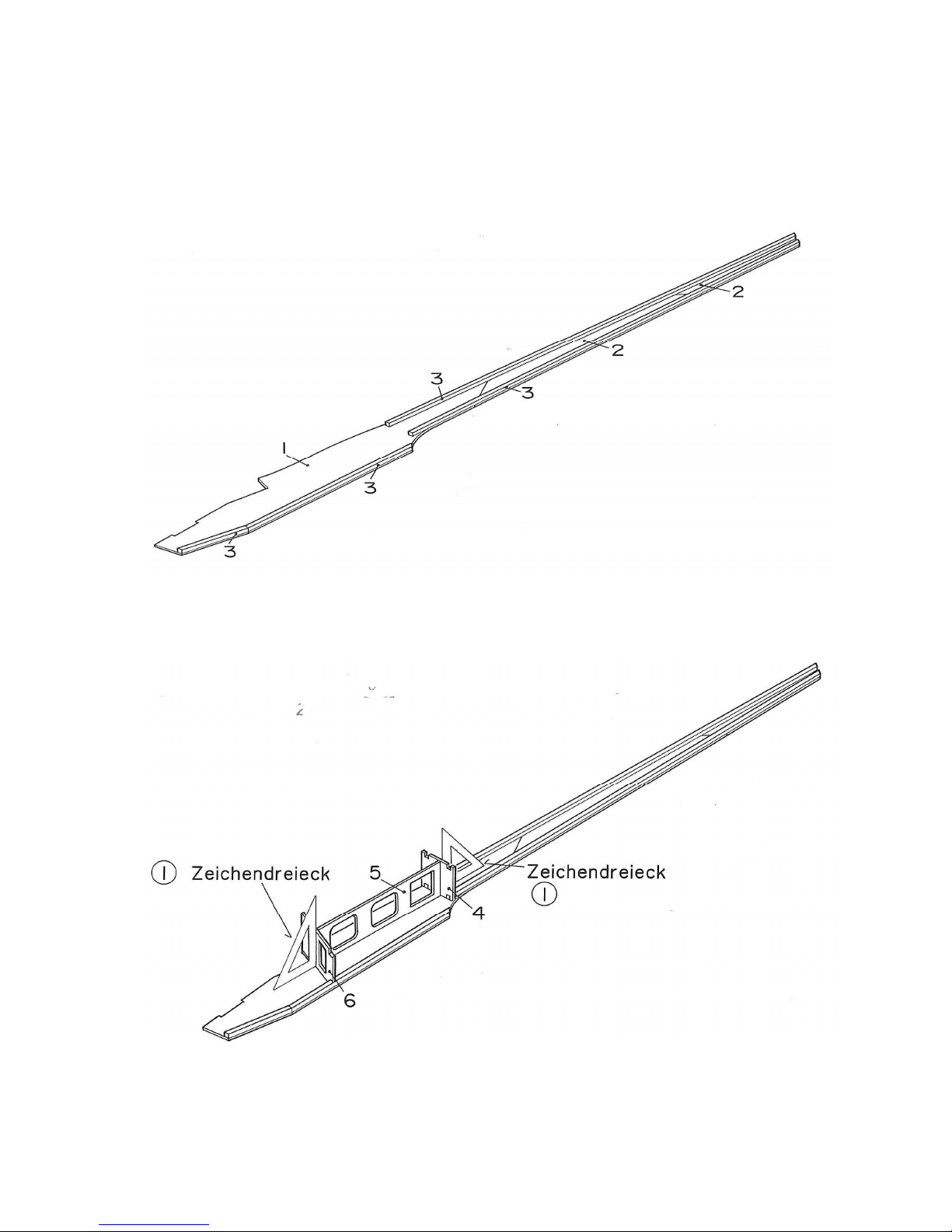
Lay plan sheet 1 down on the building board, locate the area showing the fuselage
side, and cover it with clear plastic film to prevent the parts sticking to the paper later.
Glue together the right-hand fuselage side components (parts 1 and 2), and pin them
down accurately over the drawing on the plan. Glue the fuselage longerons (3) to
parts (1) and (2) exactly flush with the outside edges.
Assemble the left-hand fuselage side, working directly over the plan in the same way.
It is essential to note that the left-hand fuselage side needs to be removed from
the building board and turned over before the longerons are fitted; this produces a “handed pair” of sides.
Glue the formers (4) and (6) and the servo plate (5) to one fuselage side, and set
them exactly upright using a set-square. Pin them in place until the glue has set hard.
Page 4
GRAUPNER/SJ GmbH D-73230 KIRCHHEIM/TECK GERMANY
Modifications reserved. No liability for printing errors. 3/2013
- 4 -
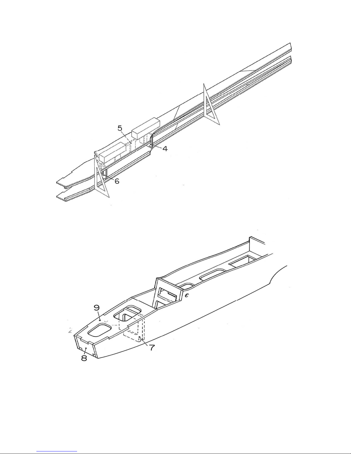
The prepared left-hand fuselage side can now be trial-fitted and glued to the fuselage
framework. It is essential to check that the two fuselage sides line up accurately.
Weight the second side down as shown in the sketch until the glue has set hard.
The drawing shows the nose area of the fuselage. The next step is to glue the formers (7) and (8) and the nose reinforcement (9) in place as shown. Caution: the
fuselage must be straight and symmetrical. You can check this by placing the
fuselage over the plan (fuselage plan view). Fix the parts together with modelling pins
or tape until the glue has set hard.
Page 5
GRAUPNER/SJ GmbH D-73230 KIRCHHEIM/TECK GERMANY
Modifications reserved. No liability for printing errors. 3/2013
- 5 -
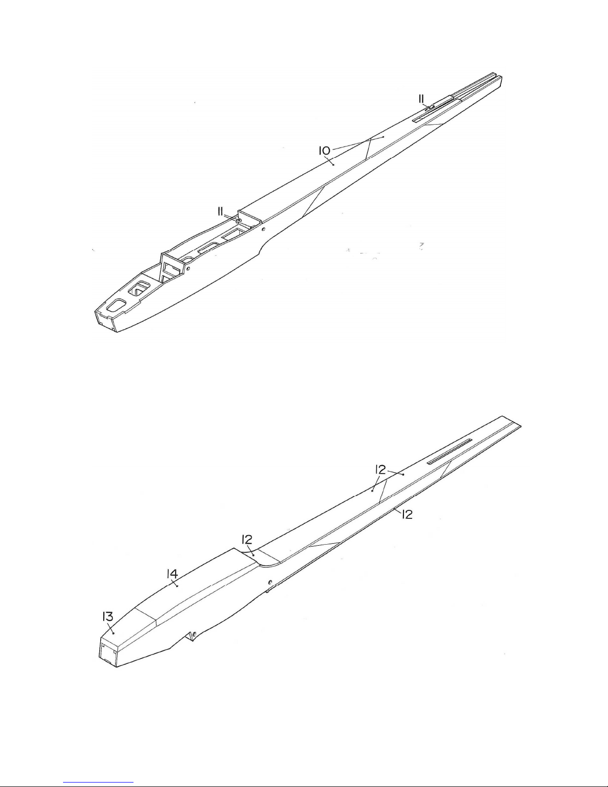
Carefully sand the top of the fuselage using a sanding block before gluing the top
decking panels (10) in place. Temporarily fit the “snake” outer sleeves (11) and trim
the exit slots if necessary. Fit an inner tube in each sleeve to check that they move
smoothly. When you are satisfied, glue the snake outers to the fuselage using UHU
ALLESKLEBER Kraft or cyano.
The sketch shows the bottom fuselage panels (12) to (14) glued in place; sand the
underside using a sanding block beforehand, as described earlier.
Page 6

GRAUPNER/SJ GmbH D-73230 KIRCHHEIM/TECK GERMANY
Modifications reserved. No liability for printing errors. 3/2013
- 6 -
Glue the shaped upper nose panel (15) in place. Sand the front face of the fuselage
flat before gluing the noseblock (16) in place. Glue the flanged nut (17) to the tailplane support (18) and glue it to the fuselage as shown.
Assemble the fin and rudder from parts (19) to (21) using cyano. Refer to section D-D
on plan sheet 1; do not use activator spray for these joints. Sand the fin to the profile
shown in section D-D, and check that the rudder deflects freely to both sides. Trial-fit
the fin assembly in the slot in the fuselage. Check from the nose of the fuselage that
the fin is exactly vertical, then glue it in place permanently.
Page 7

GRAUPNER/SJ GmbH D-73230 KIRCHHEIM/TECK GERMANY
Modifications reserved. No liability for printing errors. 3/2013
- 7 -
Trim parts (22) and (23) to fit on the fuselage, and trial-fit the locating pieces (23) and
(23a). Glue the parts together, and tape them to the fuselage while the glue is drying;
take care not to glue them to the fuselage itself. Carefully trim the moulded canopy to
final size, and glue it to the canopy frame using UHU ALLESKLEBER Kraft.
Allow all the glued joints to set hard before rounding off the fuselage to the profile
shown in sections E-E and F-F, using a balsa plane and sanding block. This process
produces a good-looking, streamlined fuselage, and also saves considerable weight.
Tailplane
Lay plan sheet 1 on the building board, and cover the tailplane area with clear plastic
film to avoid the components sticking to the plan later. Assemble parts (26) to (42) as
Page 8

GRAUPNER/SJ GmbH D-73230 KIRCHHEIM/TECK GERMANY
Modifications reserved. No liability for printing errors. 3/2013
- 8 -
shown on the plan and in the drawing, and glue all the joints, referring to sections AA and C-C. When the glue is dry, sand the tailplane framework, round off the tip
blocks (42) and shape the elevator (43) as shown on the plan using a sanding block.
When the tailplane has been covered, the elevator can be attached using a fulllength tape hinge, as shown in the sketch.
Wings
The first stage here is to assemble the right-hand inboard wing panel: cover the appropriate area of the plan with clear plastic film as already described, then pin down
the leading edge (44), spar (50) and trailing edge (45). Fit the 0.8 mm packing strip
under the trailing edge as shown in section H-H. Glue the wing ribs (46) to (49) in
place. Note that the ribs (46) have to be set at an angle using the template (98).
Allow the glue to set hard, then remove the wing panel from the building board and
glue the bottom spar (50) to the structure.
Roughen (sand) the outside of the brass tube (51) and glue it in place using cyano.
Fit the in-fill pieces (52) using plenty of glue, followed by the reinforcements (53) and
the spar webs (54).
The outboard wing panel is constructed on the same principle.
Before building the left wing panel rub a little thin plant oil into the plan to render it
translucent; see the note on the plan. The left-hand wing panels can then be assembled on the back of the plan using the familiar procedure.
Page 9

GRAUPNER/SJ GmbH D-73230 KIRCHHEIM/TECK GERMANY
Modifications reserved. No liability for printing errors. 3/2013
- 9 -
The inboard and outboard wing panels can now be joined: first trial-fit the parts, then
glue them together using the reinforcements (68) to (73). Glue the incidence pegs
(74) in the root ribs. Allow the glue to set hard, then carefully sand the whole wing
before gluing the sheet panels (75) to (78) to the structure.
When fitting the sheet panels it is essential to keep the wing flat on the building board
to avoid warps. It is best to glue the sheeting in place using cyano sparingly, and
then to apply more glue to the joints, working from the underside. Sand the joined
wing overall as shown in section H-H, and round off the wingtips (79). Finally check
that the two wings fit together snugly at the root. Glue the trailing edge reinforcement
rods (81) in place, and secure them with nylon tape (21), again fixed using cyano.
Covering
The whole model can now be covered with iron-on film (not included). The fuselage
requires several sections of film: start with the underside, then the nose area and the
turtle deck, and finish with the fuselage sides. Each wing is covered with four film
panels, always starting with the underside. Cover each panel of the tail group individually. It is important to avoid warps creeping into the structure when the film is
applied and shrunk. The final part of the covering procedure is to apply the selfadhesive name placards.
RC installation
Screw the tailplane to the fuselage using parts (92) and (93).
Fit the servos in the fuselage and screw them in place (the retaining screws and
output devices are included in the servo accessory packs). Install the two horns using
parts (87) to (90). Connect the control snakes, install the remaining receiving system
components, and check the working systems from the transmitter. If the control surfaces are not central, screw the clevises in or out on the threaded couplers to correct.
Attach the wing to the fuselage using the four rubber bands (99).
Page 10

GRAUPNER/SJ GmbH D-73230 KIRCHHEIM/TECK GERMANY
Modifications reserved. No liability for printing errors. 3/2013
- 10 -
Balancing
Assemble the model completely for balancing, i.e. with the whole RC system fitted.
The correct Centre of Gravity is at a point 115 mm from the wing leading edge,
measured at the root.
Check the C.G. by supporting the model under the wing on two fingertips at the point
indicated: the model should now balance level. Add lead ballast to the extreme nose
until the model remains horizontal. Note: the C.G. of the AMIGO IV is further aft than
normal due to the lifting airfoil of the tailplane.
Longitudinal dihedral
The longitudinal dihedral, i.e. the difference in incidence between the wing datum and
the tailplane datum, should be 1.5° to 2°. If you h ave built the model accurately and
in accordance with the plan, this will automatically be correct. If you are not sure of
this, or if the model needs to be checked after a repair, simply refer to the sketch
below.
Flying
Assemble the model completely, charge all the batteries, and check that the control
surfaces are properly centred before undertaking the first flight. Wait for a day with
little or no breeze. A good flying site is a flat grassy field, ideally with a gentle slope
facing into wind.
Note: for the initial test-glide push the model forward directly into any wind; the
fuselage nose should be angled down slightly (by about 10°). If necessary apply
very slight rudder and elevator commands to keep the model gliding straight and flat.
Fine-tuning is carried out using the trim sliders below and adjacent to the transmitter
sticks. Always land the model directly into wind.
All of us at Graupner/SJ Modellbau hope you enjoy many fine flights with your new
AMIGO IV
Page 11

GRAUPNER/SJ GmbH D-73230 KIRCHHEIM/TECK GERMANY
Modifications reserved. No liability for printing errors. 3/2013
- 11 -
Parts List
No.
Description
Quant.
Material
Dimensions
in mm
1 Front fuselage side 2 Plywood Laser-cut, 3
2 Rear fuselage side 2 x 1+1 Balsa Laser-cut, 3
3 Fuselage longeron 8 Balsa Oversize, 5 x 5
4 Fuselage former 1 Plywood Laser-cut, 3
5 Servo plate 1 Plywood Laser-cut, 3
6 Former 1 Plywood Laser-cut, 3
7 Former 1 Plywood Laser-cut, 3
8 Nose former 1 Plywood Laser-cut, 3
9 Nose reinforcement 1 Plywood Laser-cut, 3
10 Fuselage top decking 1+1 Balsa Laser-cut, 2
11 “Snake” outer sleeve 2 Plastic Overlength, 3.2 / 2.2 Ø
12 Rear fuselage bottom 3 x 1 Balsa Laser-cut, 2
13 Front fuselage bottom 1 Balsa Oversize, 10
14 Centre fuselage bottom 1 Balsa Oversize, 15
15 Shaped nose panel 1 Balsa Oversize, 17
16 Fuselage noseblock 1 Balsa Oversize, 46
17 Flanged nut 1 Steel Ready made, M 4
18 Tailplane support 2 Plywood Laser-cut, 2
19 Fin 1+1 Balsa Laser-cut, 2
20 Rudder 1+1 Balsa Laser-cut, 2
21 Nylon tape 1 Nylon Overlength, 20 wide
22 Canopy frame 1 Plywood Laser-cut, 2
23 Canopy frame 1 Plywood Laser-cut, 2
23a Canopy locating peg 2 Hardwood Oversize, 4 Ø
24 Canopy 1 Plastic Vac.-moulded
25 Wing band dowel 2 Hardwood Oversize, 5 Ø x 80
26 Tailplane spar 2 Balsa Oversize, 3 x 5 x 624
27 Tailplane sheet panel 1 Balsa Laser-cut, 1.5
28 Tailplane sheet panel 1 Balsa Laser-cut, 1.5
29 Tailplane leading edge 1 Balsa Oversize, 6.5 x 6 x 624
30 Tailplane false trailing edge 1 Balsa Oversize, 6 x 4 x 635
31 Rib 6 Balsa Laser-cut, 1.5
32 Rib 2 Balsa Laser-cut, 1.5
33 Rib 2 Balsa Laser-cut, 1.5
34 Rib 2 Balsa Laser-cut, 1.5
35 Rib 2 Balsa Laser-cut, 1.5
36 Rib 2 Balsa Laser-cut, 1.5
37 Rib 2 Balsa Laser-cut, 1.5
38 Rib 2 Balsa Laser-cut, 1.5
39 Rib 2 Balsa Laser-cut, 1.5
40 Rib 2 Balsa Laser-cut, 1.5
41 Sheet panel 1+1 Balsa Laser-cut, 1.5
42 Tailplane tip block 2 Balsa 10, length as plan
43 Elevator 1 Balsa 33 x 5 x 635
44 Wing leading edge 2 Balsa Oversize, 10 x 5 x 615
45 Wing trailing edge 2 Balsa 20 x 5 x 615
46 Rib 2 Balsa Laser-cut, 2
47 Rib 4 Plywood Laser-cut, 2
48 Rib 2 Balsa Laser-cut, 2
49 Rib 24 Balsa Laser-cut, 2
50 Main spar 8 Spruce 5 x 3, length as plan
51 Brass tube 2 Brass 5 / 4.2 Ø x 81
52 In-fill piece 8 Spruce 5 x 3 x 32
53 In-fill piece 2 Spruce 10 x 3 x 37
54 Spar web 16 Balsa 10 x 3 x 35
55 Wing leading edge 2 Balsa Oversize, 10 x 5 x 392
56 Wing trailing edge 2 Balsa Oversize, 20 x 5 x 395
57 Rib 2 Balsa Laser-cut, 2
58 Rib 2 Balsa Laser-cut, 2
59 Rib 2 Balsa Laser-cut, 2
60 Rib 2 Balsa Laser-cut, 2
Page 12

GRAUPNER/SJ GmbH D-73230 KIRCHHEIM/TECK GERMANY
Modifications reserved. No liability for printing errors. 3/2013
- 12 -
No.
Description
Quant.
Material
Dimensions
in mm
61 Rib 2 Balsa Laser-cut, 2
62 Rib 2 Balsa Laser-cut, 2
63 Rib 2 Balsa Laser-cut, 2
64 Rib 2 Balsa Laser-cut, 2
65 Rib 2 Balsa Laser-cut, 2
66 Rib 2 Balsa Laser-cut, 2
67 Spar web 18 Balsa 37 x 7 x 3
68 Dihedral brace 2 x 1+1 Plywood Laser-cut, 2
69 Dihedral brace 4 Plywood Laser-cut, 2
70 Rib 4 Balsa Laser-cut, 2
71 Half-rib 2 Balsa Laser-cut, 2
72 Gusset 6 Balsa Laser-cut, 3
73 Gusset 2 Balsa Laser-cut, 3
74 Incidence peg 2 Hardwood Overlength, 4 Ø x 85
75 Sheet panel 2 Balsa 615 x 85 x 1.5
76 Sheet panel 2 Balsa 390 x 85 x 1.5
77 Sheet panel 4 Balsa Laser-cut, 1.5
78 Sheet panel 2 Balsa Laser-cut, 1.5
79 Tip block 2 Balsa 10, length as plan
80 Root facing rib 2 Plywood Laser-cut, 2
81 Trailing edge reinforcement 2 Steel rod 1.5 Ø x 60
82 Wing joiner rod 1 Steel Ready made, 4 Ø
83 Snake inner tube 2 Plastic Overlength, 1.85 / 0.9 Ø
84 Threaded coupler 4 Plated brass Ready made, M 2
85 Nut 4 Steel Ready made, M 2
86 Clevis 4 Steel Ready made, M 2
87 Control surface horn 1 Plastic Ready made
88 Control surface horn 1 Plastic Ready made
89 Spreader plate 2 Plastic Ready made
90 Pan-head screw 4 Steel M2 x 10
91 Hinge tape (not included) 2 Plastic 620 x 15 x 0.1
92 Countersunk screw 1 Plastic M4 x 20
93 Spreader plate 1 Plastic Ready made
94 Towhook 1 Plastic Ready made
95 Spreader plate 1 Plastic Ready made
96 Pan-head screw 2 Steel M3 x 28
97 Reinforcement 1 Plywood Laser-cut, 3
98 Angle template 2 Plywood Laser-cut, 2
99 Rubber band 4 Rubber 40 Ø x 4 x 2
100 AMIGO IV name placard 4 Self-adhesive film 380 x 140 x 0.1
The picture shows the finished airframe in its uncovered state.
Page 13

GRAUPNER/SJ GmbH D-73230 KIRCHHEIM/TECK GERMANY
Modifications reserved. No liability for printing errors. 3/2013
- 13 -
Specification - AMIGO IV
Wingspan approx. 2000 mm
Overall length approx. 1115 mm
Wing airfoil NACA 4409
Wing area approx. 37.5 dm²
Tailplane area approx. 7.5 dm²
Total surface area approx. 45.0 dm²
All-up weight approx. 1100 g
Replacement part (not included)
AMIGO IV canopy Order No. 9546.1
Safety Notes
Caution: cyano-acrylate adhesive must never be allowed to contact any part of your body, and your eyes
in particular. For this reason we recommend the use of gloves and goggles when handling these
materials. The workshop should be effectively ventilated. Store the adhesive out of the reach of children.
It is a legal requirement to obtain third-party insurance before you operate any model aircraft.
Before attempting to operate the model for the first time it is essential to read right through the operating
instructions attentively. You alone are responsible for the safe operation of your RC model aircraft. Young
persons must be supervised by a responsible adult who is aware of the possible hazards involved in the
operation of model aeroplanes.
In legal terms our models are classed as aircraft, and as such are subject to legal regulations and
restrictions which must be observed at all times.
Avoid short-circuits at all times. The high energy density of the batteries used in modelling involves a
constant risk of explosion and fire.
A radio-controlled model aircraft can only work properly and fulfil your expectations if it is built very
carefully, and in accordance with the building instructions. Nobody would climb into a full-size sailplane
and try to fly it without first completing a course of training. Model flying is just such a skill, and has to be
learned in exactly the same way.
However, as manufacturers we have no means of influencing the way you build and operate your RC
model aircraft, and for this reason we can do no more than point out the hazards expressly. We accept no
further liability.
If you need help, please enlist the aid of an experienced modeller, join a model club or enrol at a model
flying training school. Model shops and the specialist model press are also good sources of information.
The best course is always to join a club and fly at the approved model flying site.
Adhesives contain substances which can be harmful to health under certain circumstances. It is therefore
important to read and observe the notes and warnings supplied by the glue manufacturer.
The operator must be in full possession of his bodily and mental capabilities. As with car driving, it is not
permissible to fly a model aircraft under the effect of alcohol or drugs.
Make sure that all passers-by and onlookers are aware of the hazards involved in the operation of your
model. Remind spectators to keep a safe distance from the model.
Always maintain a safe distance between your model and other people or objects. Never fly low over
people or directly towards them.
Radio-controlled models should only be flown in “normal” weather conditions, i.e. a temperature range of
-5° to +35°C. More extreme temperatures can lead to changes in battery capacity, material characteristics,
the strength of glued joints and other unwanted effects.
All model flyers should behave in a way which minimises the danger to people and property. Never act in
any manner which will disturb other pilots, or have an adverse effect on safe, orderly flying at the site.
Don’t operate your model aeroplane in the vicinity of overhead power cables, industrial sites, residential
areas, public roads, school playgrounds or sports fields etc.
Page 14

GRAUPNER/SJ GmbH D-73230 KIRCHHEIM/TECK GERMANY
Modifications reserved. No liability for printing errors. 3/2013
- 14 -
Pre-flight checks
Check that the radio control system works correctly and at full range before every flight: switch on the
transmitter and receiving system, and ensure that all the control surfaces work smoothly, and deflect in
the correct “sense” in relation to the stick movements.
If you are a beginner to this type of model flying, we recommend that you enlist an experienced model
pilot to help you check and test-fly the model.
Please don’t ignore our warnings. They refer to hazardous materials and processes which, if ignored, can
result in fatal injury or serious damage to property.
If you are to fly your model safely and avoid problems, it is essential that you are aware of its position
and attitude throughout each flight - so don’t let it fly too far away. If you detect a control problem or
interference during a flight, immediately land the model to prevent a potential accident. Model aeroplanes
must always give way to full-size aircraft. Take-off and landing strips should be kept free of people and
other obstacles.
Your RC system can only work reliably if the batteries are kept fully charged.
Never use hot, faulty or damaged batteries. It is important to observe the instructions supplied by the
battery manufacturer.
Manufacturer’s declaration:
If material defects or manufacturing faults should arise in a product distributed by us in the Federal
Republic of Germany and purchased by a consumer (§ 13 BGB), we, Graupner/SJ GmbH, D-73230
Kirchheim/Teck, Germany, acknowledge the obligation to correct those defects within the limitations
described below.
The consumer is not entitled to exploit this manufacturer’s declaration if the failure in the usability of the
product is due to natural wear, use under competition conditions, incompetent or improper use (including
incorrect installation) or external influences.
This manufacturer’s declaration does not affect the consumer’s legal or contractual rights regarding
defects arising from the purchase contract between the consumer and the vendor (dealer).
Extent of the guarantee
If a claim is made under guarantee, we undertake at our discretion to repair or replace the defective
goods. We will not consider supplementary claims, especially for reimbursement of costs relating to the
defect (e.g. installation / removal costs) and compensation for consequent damages unless they are
allowed by statute. This does not affect claims based on legal regulations, especially according to
product liability law.
Guarantee requirements
The purchaser is required to make the guarantee claim in writing, and must enclose original proof of
purchase (e.g. invoice, receipt, delivery note) and this guarantee card. The purchaser must send the
defective goods to us at his own cost, using the address stated above.
The purchaser should state the material defect or manufacturing fault, or the symptoms of the fault, in as
accurate a manner as possible, so that we can check if our guarantee obligation is applicable.
The goods are transported from the consumer to us and from us to the consumer at the risk of the
consumer.
Duration of validity
This declaration only applies to claims made to us during the claim period as stated in this declaration.
The claim period is 24 months from the date of purchase of the product by the consumer from a dealer in
the Federal Republic of Germany (purchase date). If a defect arises after the end of the claim period, or if
the evidence or documents required according to this declaration in order to make the claim valid are not
presented until after this period, then the consumer forfeits any rights or claims from this declaration.
Limitation by lapse of time
If we do not acknowledge the validity of a claim based on this declaration within the claim period, all
claims based on this declaration are barred by the statute of limitations after six months from the time of
implementation; however, this cannot occur before the end of the claim period.
Applicable law
This declaration, and the claims, rights and obligations arising from it, are based exclusively on the
pertinent German Law, excluding the norms of international private law, and excluding UN retail law.
 Loading...