

Page 1

www.gm-racing.de
9
XG-6i 2.0 FHSS Sport Spec 2.4 GHz
Bedienungsanleitung
Instruction Manual
Manuel d’utilisation
Garantie - Warranty - Garantie
94002 GM-Racing XG-6i 2.0 FHSS Sport Spec
4002 GM-Racing XG-6i 2.0 FHSS Sport Spec
Deutsch 01-10
English 11-20
Francais 21-30
31
Page 2

Deutsch
FUNKTIONEN:
DAS FERNSTEUERSYSTEM
INHALTSVERZEICHNIS
SICHERHEITSHINWEISE:
Um noch lange Freude an Ihrem Modellbauhobby zu haben, lesen Sie diese Anleitung unbedingt genau durch und beachten Sie vor allem die Sicherheitshinweise. Wenn Sie Anfänger im
Bereich ferngesteuerter Modellfl ugzeuge, -schiffe oder -autos sind, sollten Sie unbedingt einen
erfahrenen Modellpiloten um Hilfe bitten.
Diese Anleitung ist bei Weitergabe des Senders unbedingt mit auszuhändigen.
Anwendungsbereich
Diese Fernsteueranlage darf ausschließlich nur für den vom Hersteller vorgesehenen Zweck,
für den Betrieb von Fahrzeug- oder Bootsmodellen eingesetzt werden. Eine anderweitige Verwendung ist verboten.
SICHERHEIT IST KEIN ZUFALL
und …
FERNGESTEUERTE MODELLE SIND KEIN SPIELZEUG
… denn auch kleine Modelle können durch unsachgemäße Handhabung erhebliche Sach- und/
oder Personenschäden verursachen.
FUNKTIONEN:
Digitale Trimmung für Gas und Lenkung mit LED-Display•
2 Proportionalkanäle und ein Schaltkanal (AUX)•
einstellbares Failsafe•
Servoreverse für Gas und Lenkung•
Servoendpunkteinstellung (EPA) einstellbar zwischen 0 - 100%•
Servoweg für Lenkung (ST.D/R) einstellbar zwischen 20 – 120%•
Sender-Unterspannungswarnung•
Sender-Ladebuchse•
DAS FERNSTEUERSYSTEM
Im Folgenden bekommen Sie einen Überblick über das XG-6i 2.0 FHSS Sport Spec 2.4 Ghz
3-Kanal Fernsteuersystem und über seine verschiedenen Funktionen und Einstellungen. V or der
ersten Inbetriebnahme sollten Sie unbedingt diese Anleitung gelesen und verstanden haben.
INHALTSVERZEICHNIS
Sicherheitshinweise .........................................................................................................1
Inbetriebnahme................................................................................................................4
Binden der Fernsteuerung.................................................................................................5
Bedienung der Fernsteuerung...........................................................................................5
AUX-Kanal (Schaltkanal)...................................................................................................5
Servowegeinstellung Lenkung (ST.D/R).............................................................................6
Failsafe Funktion.............................................................................................................. 6
Servoreverse....................................................................................................................7
Servoendpunkteinstellung (EPA)....................................................................................... 7
Trimmfunktion.................................................................................................................8
Lenkungstrimmung (ST.TRIM) .......................................................................................8
Gastimmung (TH.TRIM) ...............................................................................................8
Technische Daten ............................................................................................................9
Hinweise zum Umweltschutz ............................................................................................9
Konformität ...................................................................................................................10
Garantie .......................................................................................................................31
SICHERHEITSHINWEISE:
Um noch lange Freude an Ihrem Modellbauhobby zu haben, lesen Sie diese Anleitung unbedingt genau durch und beachten Sie vor allem die Sicherheitshinweise. Wenn Sie Anfänger im
Bereich ferngesteuerter Modellfl ugzeuge, -schiffe oder -autos sind, sollten Sie unbedingt einen
erfahrenen Modellpiloten um Hilfe bitten.
Diese Anleitung ist bei Weitergabe des Senders unbedingt mit auszuhändigen.
Anwendungsbereich
Diese Fernsteueranlage darf ausschließlich nur für den vom Hersteller vorgesehenen Zweck,
für den Betrieb von Fahrzeug- oder Bootsmodellen eingesetzt werden. Eine anderweitige Verwendung ist verboten.
SICHERHEIT IST KEIN ZUFALL
FERNGESTEUERTE MODELLE SIND KEIN SPIELZEUG
… denn auch kleine Modelle können durch unsachgemäße Handhabung erhebliche Sach- und/
oder Personenschäden verursachen.
und …
01 94002 GM-Racing XG-6i 2.0 FHSS Sport Spec
Page 3

Technische Defekte elektrischer oder mechanischer Art können zum unverhofften Anlau-
Technische Defekte elektrischer oder mechanischer Art können zum unverhofften Anlau-
•
fen eines Motors und/oder zu herumfl iegenden Teilen führen, die nicht nur Sie erheblich
verletzen können!
Kurzschlüsse jeglicher Art sind unbedingt zu vermeiden! Durch Kurzschluss können nicht
•
nur Teile der Fernsteuerung zerstört werden, sondern je nach dessen Umständen und dem
Energiegehalt des Akkus besteht darüber hinaus akute Verbrennungs- bis Explosionsgefahr. Alle durch einen Motor angetriebenen Teile wie Luft- und Schiffsschrauben, Rotoren
bei Hubschraubern, offene Getriebe usw. stellen eine ständige Verletzungsgefahr dar. Sie
dürfen keinesfalls berührt werden! Achten Sie darauf, dass auch kein sonstiger Gegenstand
mit angetriebenen Teilen in Berührung kommt!
Bei angeschlossenem Antriebsakku oder laufendem Motor gilt: Halten Sie sich niemals im
•
Gefährdungsbereich des Antriebs auf!
Achten Sie auch während der Programmierung unbedingt darauf, dass ein angeschlosse-
•
ner Verbrennungs- oder Elektromotor nicht unbeabsichtigt anläuft. Unterbrechen Sie ggf.
die Treibstoffversorgung bzw. stecken Sie den Antriebsakku zuvor ab.
Schützen Sie alle Geräte vor Staub, Schmutz, Feuchtigkeit und anderen Fremdteilen. Set-
•
zen Sie diese niemals Vibrationen sowie übermäßiger Hitze oder Kälte aus. Der Fernsteuerbetrieb darf nur bei „normalen“ Außentemperaturen durchgeführt werden, d. h. in einem
Bereich von -15°C bis +55°C.
Vermeiden Sie Stoß- und Druckbelastung. Überprüfen Sie die Geräte stets auf Beschädi-
•
gungen an Gehäusen und Kabeln. Beschädigte oder nass gewordene Geräte, selbst wenn
sie wieder trocken sind, nicht mehr verwenden!
Es dürfen nur die von uns empfohlenen Komponenten und Zubehörteile verwendet wer-
•
den. Verwenden Sie immer nur zueinander passende, original GRAUPNER Steckverbindungen gleicher Konstruktion und gleichen Materials.
Achten Sie darauf, dass alle Steckverbindungen fest sitzen.
•
Beim Lösen von Steckverbindungen nicht an den Kabeln ziehen.
•
Es dürfen keinerlei Veränderungen an den Geräten durchgeführt werden. Vermeiden Sie
•
Verpolungen und Kurzschlüsse jeglicher Art, die Geräte sind dagegen nicht geschützt.
•
fen eines Motors und/oder zu herumfl iegenden Teilen führen, die nicht nur Sie erheblich
verletzen können!
Kurzschlüsse jeglicher Art sind unbedingt zu vermeiden! Durch Kurzschluss können nicht
•
nur T eile der F ernsteuerung zerstört werden, sondern je nach dessen Umständen und dem
Energiegehalt des Akkus besteht darüber hinaus akute Verbrennungs- bis Explosionsgefahr. Alle durch einen Motor angetriebenen Teile wie Luft- und Schiffsschrauben, Rotoren
bei Hubschraubern, offene Getriebe usw. stellen eine ständige Verletzungsgefahr dar. Sie
dürfen keinesfalls berührt werden! Achten Sie darauf , dass auch kein sonstiger Gegenstand
mit angetriebenen Teilen in Berührung kommt!
Bei angeschlossenem Antriebsakku oder laufendem Motor gilt: Halten Sie sich niemals im
•
Gefährdungsbereich des Antriebs auf!
Achten Sie auch während der Programmierung unbedingt darauf, dass ein angeschlosse-
•
ner Verbrennungs- oder Elektromotor nicht unbeabsichtigt anläuft. Unterbrechen Sie ggf.
die Treibstoffversorgung bzw. stecken Sie den Antriebsakku zuvor ab.
Schützen Sie alle Geräte vor Staub, Schmutz, Feuchtigkeit und anderen Fremdteilen. Set-
•
zen Sie diese niemals Vibrationen sowie übermäßiger Hitze oder Kälte aus. Der Fernsteuerbetrieb darf nur bei „normalen“ Außentemperaturen durchgeführt werden, d. h. in einem
Bereich von -15°C bis +55°C.
Vermeiden Sie Stoß- und Druckbelastung. Überprüfen Sie die Geräte stets auf Beschädi-
•
gungen an Gehäusen und Kabeln. Beschädigte oder nass gewordene Geräte, selbst wenn
sie wieder trocken sind, nicht mehr verwenden!
Es dürfen nur die von uns empfohlenen Komponenten und Zubehörteile verwendet wer-
•
den. Verwenden Sie immer nur zueinander passende, original GRAUPNER Steckverbindungen gleicher Konstruktion und gleichen Materials.
Achten Sie darauf, dass alle Steckverbindungen fest sitzen.
•
Beim Lösen von Steckverbindungen nicht an den Kabeln ziehen.
•
Es dürfen keinerlei Veränderungen an den Geräten durchgeführt werden. Vermeiden Sie
•
Verpolungen und Kurzschlüsse jeglicher Art, die Geräte sind dagegen nicht geschützt.
Einbau der Empfangsanlage und Verlegen der Empfangsantenne
Der Empfänger muß gegen Staub und Spritzwasser geschützt untergebracht werden.•
Der Empfänger darf an keiner Stelle unmittelbar am Chassis anliegen, da sonst Motorer-•
schütterungen oder Stöße direkt auf ihn übertragen werden.
Beim Einbau der Empfangsanlage in ein Modell mit Verbrennungsmotor alle Teile immer •
geschützt einbauen, damit keine Abgase oder Ölreste eindringen können.
Den Empfänger so festlegen, dass die Antenne und die Anschlusskabel zu den Servos und •
zum Stromversorgungsteil locker liegen.
Die Empfängerantenne darf nicht geknickt oder gekürzt werden! • Die eigentliche „An-
tenne“ ist das abisolierte Ende des Antennenkabels und muß soweit oben wie
möglich im Fahrzeug installiert werden. Vermeiden Sie Beschädigungen des
Antennenkabels!
Deutsch
Einbau der Servos
Servos stets mit den beigefügten Vibrationsdämpfergummis befestigen. Nur so sind diese •
vor allzu harten Vibrationsschlägen einigermaßen geschützt.
Einbau der Gestänge
Grundsätzlich muss der Einbau so erfolgen, dass die Gestänge frei und leichtgängig laufen. •
Besonders wichtig ist, dass alle Ruderhebel ihre vollen Ausschläge ausführen können, also
nicht mechanisch begrenzt werden.
94002 GM-Racing XG-6i 2.0 FHSS Sport Spec 02
Page 4

Deutsch
Um einen laufenden Motor jederzeit anhalten zu können, muss das Gestänge so eingestellt •
sein, dass das Vergaserküken ganz geschlossen wird, wenn Steuerknüppel und Trimmhebel in die Leerlaufendstellung gebracht werden.
Achten Sie darauf, dass keine Metallteile, z. B. durch Ruderbetätigung, Vibration, drehen-•
de Teile usw., aneinander reiben. Hierbei entstehen so genannte Knackimpulse, die den
Empfänger stören.
Modellbetrieb
Gefährden Sie niemals Menschen oder Tiere. Betreiben Sie Ihr Schiffsmodell auch nicht in •
der Nähe von Schleusen und öffentlicher Schifffahrt. Betreiben Sie Ihr Automodell ebenso
wenig auf öffentlichen Straßen und Autobahnen, Wegen und Plätzen etc..
Kontrolle Sender- und Empfängerbatterie
Kontrollieren Sie regelmäßig den Zustand der Akkus, insbesondere des Empfängerakkus. •
Warten Sie nicht so lange, bis die Bewegungen der Rudermaschinen merklich langsamer
geworden sind! Ersetzen Sie verbrauchte Akkus rechtzeitig.
Es sind stets die Ladehinweise des Akkuherstellers zu beachten und die Ladezeiten unbe-•
dingt genau einzuhalten.
Laden Sie Akkus niemals unbeaufsichtigt auf. •
Versuchen Sie niemals, Trockenbatterien aufzuladen (Explosionsgefahr).•
Alle Akkus müssen vor jedem Betrieb geladen werden.•
Um Kurzschlüsse zu vermeiden, zuerst die Bananenstecker der Ladekabel polungsrichtig •
am Ladegerät anschließen, dann erst Stecker des Ladekabels an den Ladebuchsen von
Sender und Empfängerakku anschließen.
Trennen Sie immer alle Stromquellen von ihrem Modell, wenn Sie es längere Zeit nicht •
mehr benützen wollen.
Kapazität und Betriebszeit
Für alle Stromquellen gilt: Die Kapazität verringert sich mit jeder Ladung. Bei niedrigen •
Temperaturen nimmt die Kapazität darüber hinaus stark ab, daher sind die Betriebszeiten
bei Kälte kürzer.
Häufi ges Laden oder Benutzen von Batteriepfl egeprogrammen kann ebenfalls zu allmähli-•
cher Kapazitätsminderung führen, deshalb sollten Stromquellen spätestens alle 6 Monate
auf ihre Kapazität hin überprüft und bei deutlichem Leistungsabfall ersetzt werden.
Erwerben Sie nur Original GRAUPNER-Akkus!•
Pfl egehinweise
Reinigen Sie Gehäuse, Senderantenne etc. niemals mit Reinigungsmitteln, Benzin, Wasser •
und dergleichen, sondern ausschließlich mit einem trockenen, weichen Tuch.
Die Fa. GRAUPNER übernimmt für nicht freigegebene Teile oder Zubehörprodukte von anderen
Herstellern keine Haftung und kann auch nicht jedes einzelne Fremdprodukt beurteilen, ob es
ohne Sicherheitsrisiko eingesetzt werden kann.
Haftungsausschluss/Schadenersatz
Sowohl die Einhaltung der Montage- und Betriebsanleitung als auch die Bedingungen und
Methoden bei Installation, Betrieb, Verwendung und Wartung der Fernsteuerkomponenten
können von der Fa. GRAUPNER nicht überwacht werden. Daher übernimmt die Fa. GRAUPNER
keinerlei Haftung für Verluste, Schäden oder Kosten, die sich aus f ehlerhafter V erwendung und
Betrieb ergeben oder in irgendeiner Weise damit zusammenhängen.
03 94002 GM-Racing XG-6i 2.0 FHSS Sport Spec
Page 5

Soweit gesetzlich zulässig, ist die Verpfl ichtung der Fa. GRAUPNER zur Leistung von Scha-
SENDERBESCHREIBUNG
INBETRIEBNAHME
denersatz, gleich aus welchem Rechtsgrund, begrenzt auf den Rechnungswert der an dem
schadensstiftenden Ereignis unmittelbar beteiligten Warenmenge der Fa. GRAUPNER.
Dies gilt nicht, soweit die Fa. GRAUPNER nach zwingenden gesetzlichen Vorschriften wegen
Vorsatzes oder grober Fahrlässigkeit unbeschränkt haftet.
SENDERBESCHREIBUNG
Antenne
EPA Lenkung
AUX-Kanal
Servo-Reverse
Lenkung
Power LED
Ein/Aus-Schalter
LED Servoweg
Ladebuchse
Failsafe
Servo-Reverse
Gas
Lenkungstrimmung
Lenkrad
Gastrimmung
Gashebel
Servoweg Lenkung
EPA Gas
Batteriefach
Deutsch
Deutsch
INBETRIEBNAHME
Legen Sie zuerst 1. 8 AA-Batterien oder Akkus in das Batteriefach im Senderfuß ein.
Achten Sie dabei auf die richtige Polung, da der Sender sonst beschädigt werden kann.
Sollten Sie die Fernsteuerung längere Zeit nicht benutzen, ist es ratsam, die Batterien aus
dem Sender zu entfernen.
2. Schließen Sie Ihre Komponenten am Empfänger an.
Batt. (4.8 - 6.0 V)
Kanal 3 - AUX
Kanal 2 - Gas
Kanal 1 - Lenkung
I +
I +
I +
I +
-
-
-
-
Achtung:
Der Sender ist mit einer Futaba-Ladebuchse ausgestattet, verwenden Sie bitte daher nur das Ladekabel Best.-Nr.: 3022.65! Bei Verwendung des Graupner-Ladekabels können die Akkus zerstört werden.
Seien Sie beim Einbau des Empfängers vorsichtig. Das Koax-Antennenkabel darf
auf keinen Fall geknickt oder gekürzt werden! Die eigentliche „Antenne“ ist das abisolierte Ende des Antennenkabels und muß soweit oben wie möglich im Fahrzeug
installiert werden. Vermeiden Sie Beschädigungen des Antennenkabels!
94002 GM-Racing XG-6i 2.0 FHSS Sport Spec 04
Page 6
BEDIENUNG DER FERNSTEUERUNG
Deutsch
BINDEN DER FERNSTEUERUNG
BINDEN DER FERNSTEUERUNG
1. Schalten Sie zuerst den Sender ein. Drücken Sie anschließend den Binding-Taster auf der
Oberseite des Empfängers und halten ihn.
2. Schalten Sie nun auch den Empfänger ein. Die Bind-LED wird kurz rot blinken, nach ein
paar Sekunden leuchtet sie dann dauerhaft grün. Nun können Sie den Binding-Knopf am
Empfänger loslassen.
3. Der Bindungsvorgang ist abgeschlossen, wenn die Bind-LED am Empfänger dauerhaft
grün leuchtet.
Binding-Taster
Bind-LED
Achtung:
1. Während des Binding-Vorgangs sollten Sender und Empfänger nicht mehr als einen Met er auseinander und außerdem im Umkreis von 10 Metern kein weiteres 2.4 GHz Gerät (z.B.
WLAN) eingeschaltet sein.
2. Ist der Bindungsvorgang abgeschlossen, brauchen Sie ihn für diese Sender-Empfänger kombination nicht mehr durchführen.
3. Sollte der Bindungsvorgang fehlschlagen (Bind-LED blinkt weiterhin rot), versuchen Sie es
erneut.
BEDIENUNG DER FERNSTEUERUNG
• Fahren Sie Ihr Modell nie mit schwachen Sender- oder Empfängerbatterien.
Sollte die Power-LED am Sender blinken, Betrieb sofort einstellen und Batteri-
en ersetzen oder Akkus laden!
• Lassen Sie den EIN/AUS-Schalter nie nach der Fahrt an, sonst halten die Batterien nicht
lange.
• Schalten Sie immer zuerst den Sender, und danach den Empfänger ein.
• Nach dem Fahren immer zuerst den Empfänger und dann den Sender ausschalten.
• Für optimalen Einsatz müssen Sie sowohl die Lenkungstrimmung als auch die Gastrimmung
korrekt einstellen.
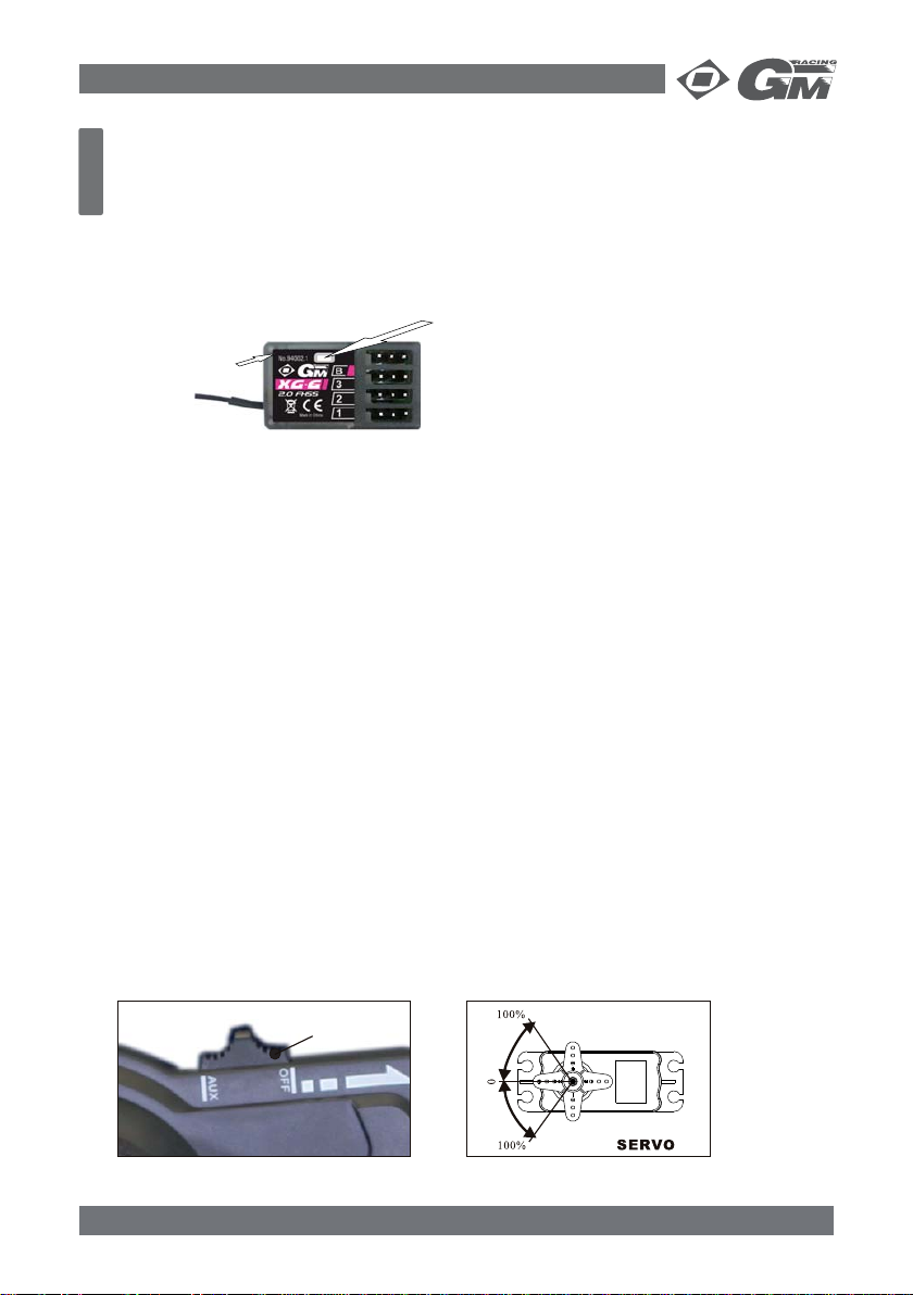
SCHALTKANAL (AUX - CH3)
Der 3. Kanal ist als reiner Schaltkanal ausgelegt und nicht einstellbar. Das angeschlossene
Servo macht dabei eine Bewegung von 90°.
Ist der Schalter in Position „AUX“, dreht sich das Servo im Uhrzeigersinn, in Position „OFF“
gegen den Uhrzeiger.
AUX-Schalter
„AUX“
„OFF“
05 94002 GM-Racing XG-6i 2.0 FHSS Sport Spec
Page 7
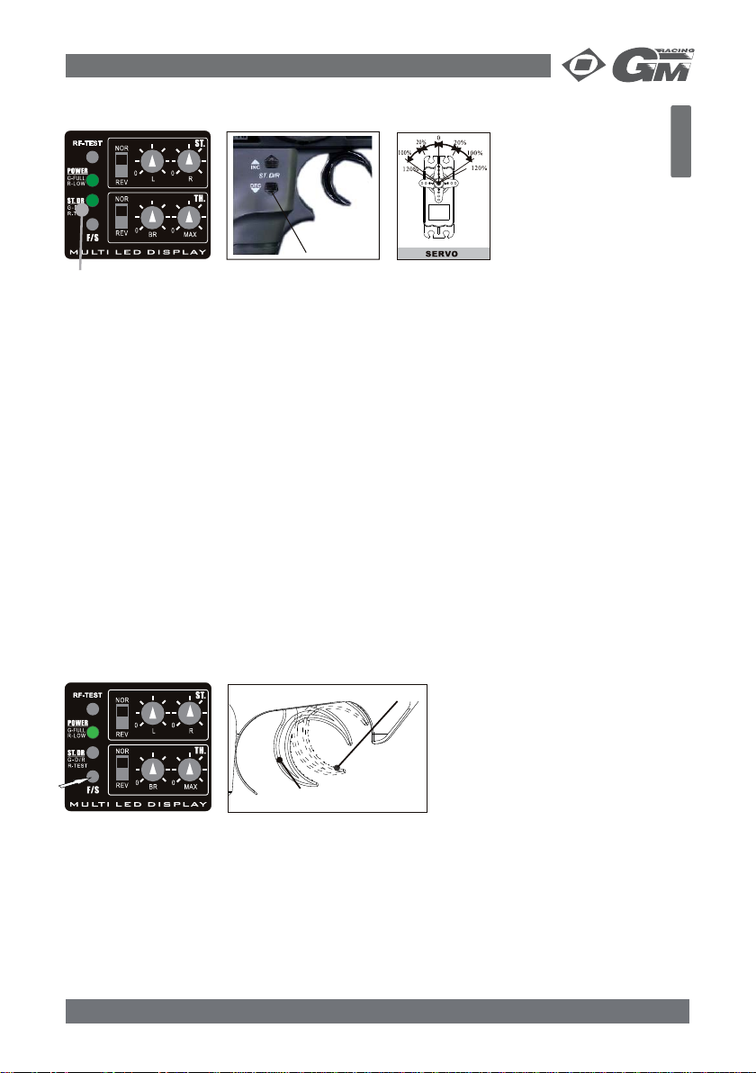
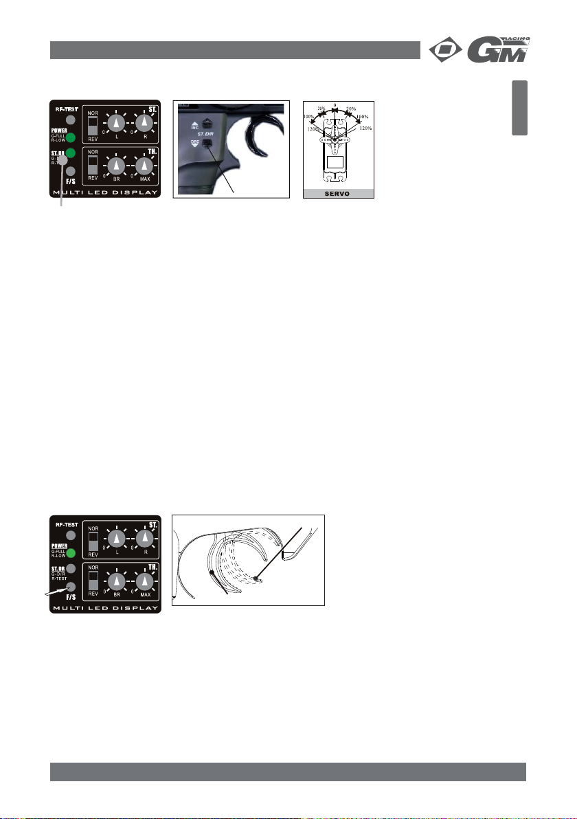
SERVOWEGEINSTELLUNG LENKUNG (ST.D/R)
Deutsch
blinkt
ST.D/RSchalter
links
rechts
Mit dieser Funktion kann der maximale Lenkeinschlag des Servos verändert werden. Die
Werkseinstellung ist 100%. Minimal kann 20% eingestellt werden, der max. Ausschlag ist
120%.
1. Drücken Sie die INC-Taste um den Servoweg zu vergrößern, die ST.DR-LED blinkt dabei
grün. Leuchtet die LED rot, haben Sie den maximalen Ausschlag erreicht.
2. Drücken Sie die DEC-Taste um den Servoweg zu verkleinern, die ST.DR-LED blinkt dabei
grün. Leuchtet die LED rot, haben Sie den minimalen Ausschlag erreicht.
3. Die ST.DR-LED leuchtet kurz rot, wenn Sie genau 20%, 100% und 120% Servoweg einge-
stellt haben, ansonsten geht sie nach dem Einstellvorgang aus.
Achtung:
Durch gleichzeitiges Drücken der INC und DEC- Taster erfolgt ein Reset des Senders.
Die T rimmungen gehen in neutral, der Serv oweg (ST.D/R) geht auf Werkseinstellung, auch die
Failsafe Funktion wird zurückgesetzt.
FAILSAFE FUNKTION
Die XG-6i 2.0 FHSS ist mit einer integrierten Failsafe Funktion ausgestattet, im Falle einer
Störung oder leerer Senderbatterien wird das Lenkservo auf Neutral-Position gebracht. Die
Position des Gasservos ist einstellbar, sollte aber bei einem Verbrennermodell auf jeden Fall auf
Vollbremse gestellt werden, bei einem Elektromodell ebenfalls auf V ollbremse oder Neutral, um
Schäden am Modell zu vermeiden.
Gashebelposition Bremse Nitromodelle
Gashebelposition Bremse
Elektromodelle
Einstellung
1. Stellen Sie sicher, dass die Sender- und Empfängerbatterien /-akkus ausreichend voll
sind.
2. Stellen Sie den Gashebel in die gewünschte Position (z.B. Vollbremse) und halten ihn. Drücken
den „F/S“ Taster solange, bis die ST.DR-LED rot blinkt.
3. Lassen Sie den „F/S“-Taster wieder los, Failsafe ist nun programmiert.
94002 GM-Racing XG-6i 2.0 FHSS Sport Spec 06
Page 8
Deutsch
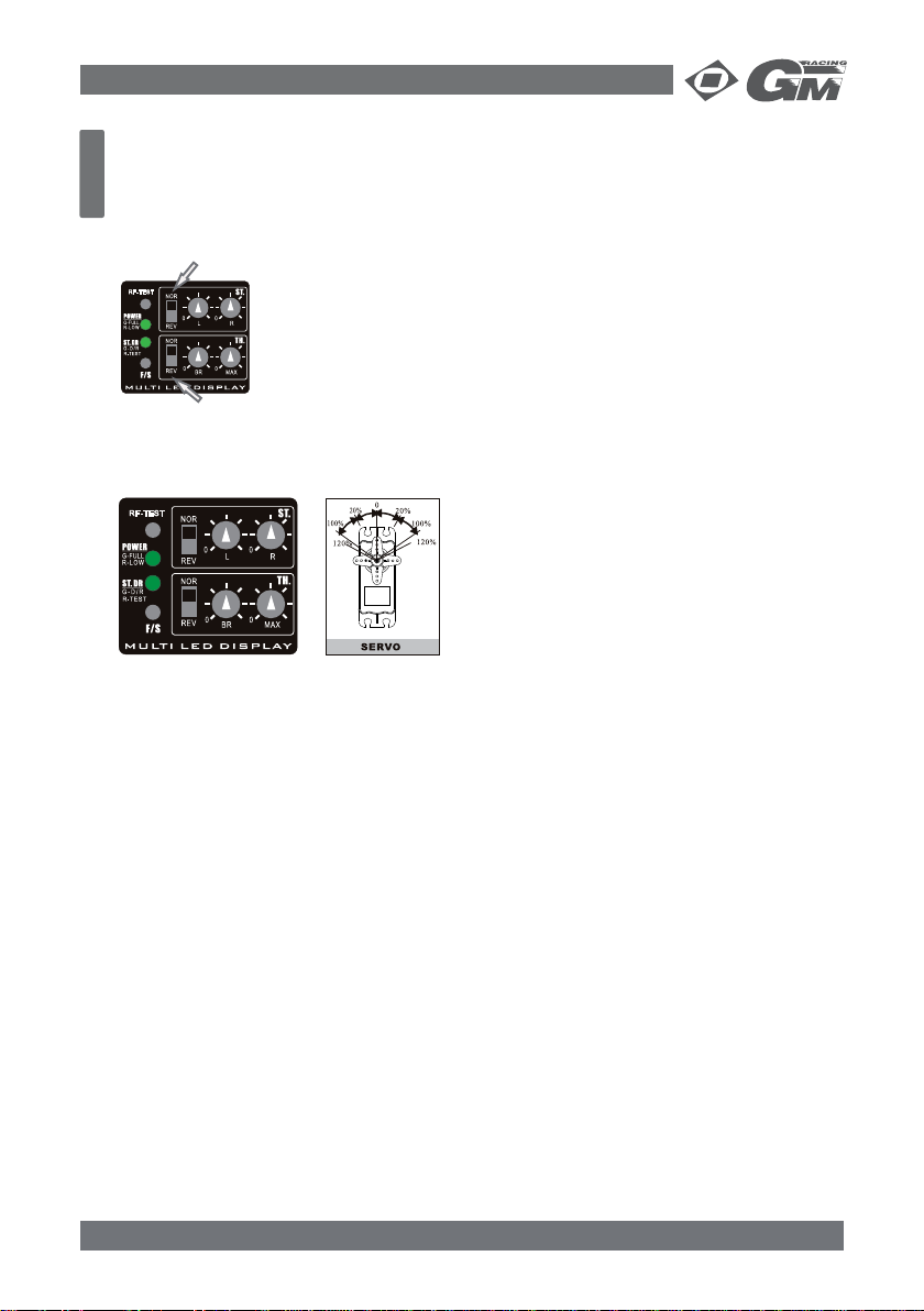
SERVOREVERSE (ST./TH.REV)
Sie können die Drehrichtung der Servos mit den Servoreverse-Schaltern im linken Display
ändern. Der obere ST-Schalter ändert die Drehrichtung des Lenkservos (Kanal 1), der untere
TH-Schalter die des Gasservos (Kanal 2). NOR bedeutet normale Drehrichtung (oben), REV
ändert die Drehrichtung (unten).
Servoreverse Lenkung
Servoreverse Gas
SERVOENDPUNKTEINSTELLUNG (EPA)
links
rückw.
rechts
vorw.
Mit dieser Funktion können Sie den maximalen Servoweg zwischen 0 und 100% für Kanal 1
(Lenkung) und Kanal 2 (Gas) einstellen.
Einstellung:
1. Lenkung (links)
Drehen Sie den Drehregler ST.L auf die gewünschte Position. Ganz links auf der P osition 0
macht das Servo keine Bewegung, ganz rechts wird der volle Servoausschlag erreicht.
2. Lenkung (rechts)
Drehen Sie den Drehregler ST.R auf die gewünschte Position. Ganz links auf der Position 0
macht das Servo keine Bewegung, ganz rechts wird der volle Servoausschlag erreicht.
3. Vorwärts
Drehen Sie den Drehregler TH.MAX auf die gewünschte Position. Ganz links auf der Positi on 0 macht das Servo keine Bewegung, ganz rechts wird der volle Servoausschlag er reicht.
4. Bremse/Rückwärts
Drehen Sie den Drehregler TH.BR auf die gewünschte Position. Ganz links auf der Position
0 macht das Servo keine Bewegung, ganz rechts wird der volle Servoausschlag erreicht.
Achtung:
vergewissern Sie sich vor dem Einstellen, das die Drehrichtung der Servos mit der
Drehrichtung am Sender übereinstimmt. Mit der Servoreversefunktion können Sie die Drehrichtung umkehren.
Stellen Sie EPA immer so ein, dass der Servoweg nicht mechanisch am Modell begrenzt wird
(z.B. durch Anschlagen der Lenkhebel an der Vorderachse), sondern immer elektronisch durch
die Einstellung am Sender! Ansonsten werden Ihre Servos nicht lange halten.
07 94002 GM-Racing XG-6i 2.0 FHSS Sport Spec
Page 9
TRIMMFUNKTION
1. Stecken Sie alle benötigten Servos in den Empfänger und schalten dann Sender und
Empfänger ein.
2. Stellen Sie die Lenkungs- und Gastrimmung am Sender auf neutral (die ST .DR -LED leuch tet rot).
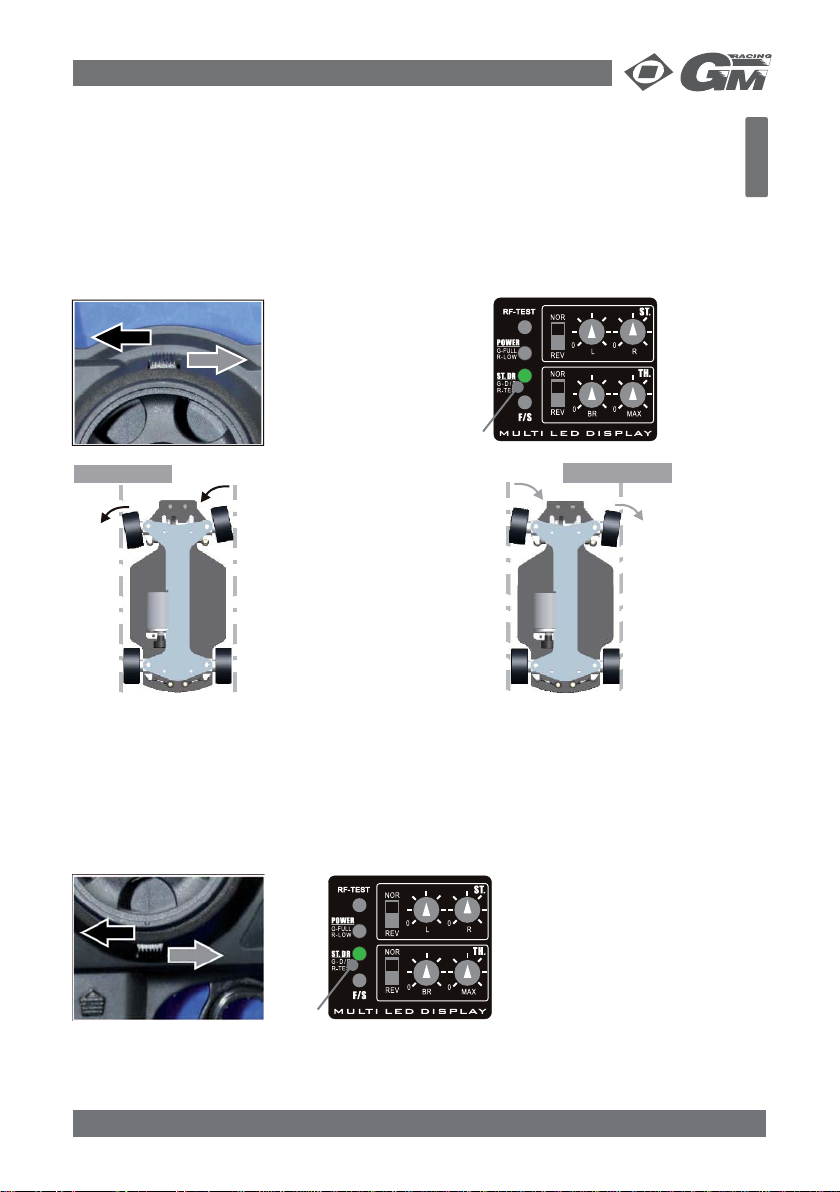
LENKUNGSTRIMMUNG (ST.TRIM)
Sie können die Lenkungstrimmung verstellen, indem Sie den Trimmhebel über dem Lenkrad
nach rechts oder links bewegen. Die ST.DR-LED zeigt die jeweilige Trimmposition an.
Achtung:
Wenn Sie beim Trimmen bemerken, dass
sich das Servo in die
falsche Richtung bewegt, müssen Sie die
Drehrichtung mit dem
Servoreverse-Schalter
umkehren!
blinkt
Links fahren Rechts fahren
Solange Sie den T rimmhebel 1.
betätigen, blinkt die ST.DRLED grün.
Sobald Sie die Mittelstellung 2.
(neutral) oder den max.
möglichen Ausschlag erreicht haben, leuchtet die
ST.DR-LED rot.
Deutsch
Tipp:
Bevor Sie ein Servo in ein Modell einbauen, sollten Sie alle Trimmpositionen auf neutral
stellen und erst dann das Servohorn oder den Servosaver aufstecken, damit er möglichst zentral sitzt. So vermeiden Sie extreme Trimmungseinstellungen.
Einstellungen an der Trimmung können den Servoweg beeinfl ussen, kontrollieren Sie daher
immer anschließend den Servoweg (ST.D/R).
GASSTRIMMUNG (TH.TRIM)
Sie können die Gastrimmung verstellen, indem Sie den Trimmhebel unterhalb des Lenkrads
nach rechts oder links bewegen. Die ST.DR-LED zeigt die jeweilige Trimmposition an.
blinkt
Tipp:
bei Verwendung eines elektronischen Fahrtenreglers stellen Sie die Trimmung am Sender auf neutral und stellen erst dann den Regler ein. Bei Verbrennermodellen sollte der Vergaser in Neutralstellung stehen. So vermeiden Sie extreme Trimmungseinstellungen.
94002 GM-Racing XG-6i 2.0 FHSS Sport Spec 08
Page 10

Deutsch
SERVICE UND REPARATUREN
In Problemfällen oder bei Fragen und Reparaturen, wenden Sie sich bitte an:
GRAUPNER-Service, Henriettenstrasse 94-96, D-73230 Kirchheim/Teck,
Tel. +49/1805/472876
Technische Daten: Sender: Empfänger:
Frequenz................................2.4 GHz FHSSS...................... 2.4 GHz FHSS
Betriebsspannung................... 9.6 V DC...............................4.8 - 6.0 V DC
Kanäle................................... 3.......................................... 3
Stromverbrauch..................... ca. 150 mA (9,6 V)................ ca. 50 mA
Servoweg.............................. 0% - 120%
Betriebstemperaturbereich...... 0° ~ +70° C
ZUBEHÖR - ERSATZTEILE:
94002.1 Empfänger für XG-6i 2.0 FHSS
94000.3 Empfängerantenne 2,4Ghz
HINWEISE ZUM UMWELTSCHUTZ
Das Symbol auf dem Produkt, der Gebrauchsanleitung oder der Verpackung weist
darauf hin, dass dieses Produkt am Ende seiner Lebensdauer nicht über den normalen Haushaltsabfall entsorgt werden darf. Es muss an einem Sammelpunkt für das
Recycling von elektrischen und elektronischen Geräten abgegeben werden.
verwendung, der stoffl ichen Verwertung oder anderen Formen der Verwertung von Altgeräten
leisten Sie einen wichtigen Beitrag zum Umweltschutz.
Batterien und Akkus müssen aus dem Gerät entfernt werden und bei einer entsprechenden
Sammelstelle getrennt entsorgt werden.
Bei RC-Modellen müssen Elektronikteile, wie z.B. Servos, Empfänger oder Fahrtenregler aus
dem Produkt ausgebaut und getrennt bei einer entsprechenden Sammelstelle als ElektroSchrott entsorgt werden.
Bitte erkundigen Sie sich bei der Gemeindeverwaltung die zuständige Entsorgungsstelle.
Die Werkstoffe sind gemäß ihrer Kennzeichnung wieder v erwertbar. Mit der Wieder-
KEINE HAFTUNG FÜR DRUCKFEHLER! ÄNDERUNGEN VORBEHALTEN!
09 94002 GM-Racing XG-6i 2.0 FHSS Sport Spec
Page 11

KONFORMITÄTSERKLÄRUNG
Deutsch
Telekomunikationsendeinrichtungen (FTEG) und der Richtlinie 1999/5/EG (R&TTE)
Konformitätserklärung gemäß dem Gesetz über Funkanlagen und
Declaration of Conformity in accordiance with the Radio and Telecomunikations Terminal Equipment
Graupner GmbH & Co. KG
Henriettenstraße 94-96
D-73230 Kirchheim/Teck
erklärt, dass das Produkt:
declares that the product
Geräteklasse: 2
Equipment class
den grundlegenden Anforderungen des § 3 und den übrigen einschlägigen Bestimmungen des
FTEG (Artikel 3 der R&TTE) entspricht.
complies with the essential requirements of § 3 and the other relevant provisions of the FTEG (Article 3 of the
R&TTE Directive).
Angewendete harmonisierte Normen:
Harmonised standards applied
EN
60950-1+A11:2009
EN
62311:2008
EN 301 489-1 V1.8.1
EN 301 489-17 V2.1.1
EN 300 328 V1.7.1
Act (FTEG) and Directive 1999/5/EG (R&TTE)
No. 94002 XG-6i 2.0
No. 94002.1 RX XG-6i 2.0
Gesundheit und Sicherheit gemäß § 3 (1) 1. (Artikel 3 (1)a))
Health and safety requirements pursuant to § 3 (1) 1. (Article 3 (1) a))
Schutzanforderungen in Bezug auf elektromagnetische
Verträglichkeit § 3 (1) 2, Artikel 3 (1) b))
Protection requirement concernig electromagnetic compatibility
§ 3 (1) 2, Artikel 3 (1) b))
Maßnahmen zur effizienten Nutzung des Frequenzspektrums
§ 3 (2) (Artikel 3 (2))
Measures for the efficient use of the radio frequency spectrum
§ 3 (2) (Article 3 (2))
0678
Kirchheim, 17. November 2010
Graupner GmbH & Co. KG Henriettenstraße 94-96 D-73230 Kirchheim/Teck Germany
Tel: 07021/722-0 EMail: info@graupner.deFax: 07021/722-188
94002 GM-Racing XG-6i 2.0 FHSS Sport Spec 10
Stefan Graupner, Geschäftsführer
Stefan Graupner, Managing Director
Page 12

FUNCTIONS:
English
• Digital Steering/Throttle Trim with LED-display
• 2 proportional channels with 1 switch channel (AUX)
• Programmable Failsafe
• Steering/Throttle Servo reverse
End-Point-Adjustment (EPA) adjustable 0% - 100%•
• Steering Dual rate (ST.D/R) adjustable 20% - 120%
• Transmitter low power indicator
• Charge socket for transmitter battery
THE REMOTE CONTROL SYSTEM
Here you get an overview of the XG-6i 2.0 FHSS Sport Spec 2.4 Ghz 3-channel remote control
system and its various functions and settings. Before the fi rst trip should be sure all of these
functions and settings have read and understood.
CONTENTS
Safety notes..................................................................................................................11
Getting started ..............................................................................................................14
Binding Process .............................................................................................................15
Operating the remote control .........................................................................................15
AUX-Channel .................................................................................................................15
Steering Range (ST.D/R) ................................................................................................16
Failsafe Function ...........................................................................................................16
Servoreverse .................................................................................................................17
End Point Adjustment (EPA) ...........................................................................................17
Trim Adjustment ............................................................................................................17
Steering Trim (ST.TRIM) .............................................................................................18
Throttle Trim (TH.TRIM) .............................................................................................18
Technical Data ..............................................................................................................19
Environmental Protection Notes ......................................................................................19
Declaration of Conformity ..............................................................................................20
Warranty ......................................................................................................................31
SAFETY NOTES
We all want you to have many hours of pleasure in our mutual hobby of modelling, and saf et y
is an important aspect of this. It is absolutely essential that you read right through these instructions and take careful note of all our safety recommendations.
If you are a beginner to the world of radio-controlled model aircraft, boats and cars, we strongly advise that you seek out an experienced modeller in your fi eld and ask him for help and
advice.
These instructions must be handed on to the new owner if you ever sell or dispose of the
transmitter.
Application
This radio control system may only be used for the purpose for which the manufacturer designed it, i.e. for operating radio-controlled models which do not carry humans. No other type of
use is approved or permissible.
SAFETY IS NO ACCIDENT
RADIO-CONTROLLED MODELS ARE NOT PLAYTHINGS
Even small models can cause serious personal injury and damage to property if they are
handled incompetently.
and
11 94002 GM-Racing XG-6i 2.0 FHSS Sport Spec
Page 13

9
2
Technical problems in electrical and mechanical systems can cause motors to rev up or
Technical problems in electrical and mechanical systems can cause motors to rev up or
•
burst into life unexpectedly, with the result that parts may fl y off at great speed, causing
series injury.
Short-circuits of all kinds must be avoided at all times. Short-circuits can easily destroy
•
parts of the radio control system, but even more dangerous is the acute risk of fi re and
explosion, depending on the circumstances and the energy content of the batteries.
Propellers (aircraft and boat), helicopter rotors, open gearboxes and all other rotating
•
parts which are driven by a motor or engine represent a permanent injury hazard. Do
not touch these items with any object or part of your body. Remember that a propeller
spinning at high speed can easily slice off a fi nger. Ensure that no other object can make
contact with the driven components.
Never stand in the primary danger zone, i. e. in the rotational plane of the propeller or
•
other rotating parts, when the motor is running or the drive battery is connected.
If an internal-combustion engine or electric motor is connected to the system, take great
•
care to avoid any possibility of it bursting into life when you are programming the transmitter. We recommend that you disconnect the fuel supply or the drive battery beforehand.
Protect all electronic equipment from dust, dirt, damp, and foreign bodies. Avoid subjec-
•
ting the equipment to vibration and excessive heat or cold. Radio control equipment should
only be used in “normal” ambient temperatures, i.e. within the range -15°C to +55°C.
Avoid subjecting the equipment to shock and pressure. Check the units at regular intervals
•
for damage to cases and leads. Do not re-use any item which is damaged or has become
wet, even after you have dried it out thoroughly.
Use only those components and accessories which we expressly recommend. Be sure to
•
use only genuine matching GRAUPNER connectors of the same design with contacts of
the same material. When deploying cables note that they must not be under tension, and
should never be bent tightly or kinked, otherwise they may fracture. Avoid sharp edges
which could wear through the cable insulation.
Check that all connectors are pushed home fi rmly before using the system. When discon-
•
necting components, pull on the connectors themselves – not on the wires.
It is not permissible to carry out any modifi cations to the RC system components. Avoid
•
reverse polarity and short-circuits of all kinds involving the connecting leads, as the equipment is not protected against such errors.
Installing the receiving system and deploying the receiver aerial
The receiver should be protected effectively from dust and spray.
•
The receiver must not make contact with the chassis at any point, otherwise motor vibra-
•
tion and landing shocks will be transmitted directly to it.
When installing the receiving system in a model powered by a glowplug or petrol engine,
•
be sure to install all the components in well-protected positions so that no exhaust gas or
oil residues can reach the units and get inside them.
Secure the receiver in such a way that the aerial, servo leads and switch harness are not
•
under any strain.
Do not bend or shorten the receiver aerial!
•
The actual „antenna“ is the stripped en of
the antenna wire and must be installed in the vehicle so far above as possible.
Avoid damages of the antenna cable!
Installing the servos
Always install servos using the vibration-damping grommets supplied. The rubber grom-
•
mets provide some degree of protection from mechanical shocks and severe vibration.
•
burst into life unexpectedly, with the result that parts may fl y off at great speed, causing
series injury.
Short-circuits of all kinds must be avoided at all times. Short-circuits can easily destroy
•
parts of the radio control system, but even more dangerous is the acute risk of fi re and
explosion, depending on the circumstances and the energy content of the batteries.
Propellers (aircraft and boat), helicopter rotors, open gearboxes and all other rotating
•
parts which are driven by a motor or engine represent a permanent injury hazard. Do
not touch these items with any object or part of your body. Remember that a propeller
spinning at high speed can easily slice off a fi nger. Ensure that no other object can make
contact with the driven components.
Never stand in the primary danger zone, i. e. in the rotational plane of the propeller or
•
other rotating parts, when the motor is running or the drive battery is connected.
If an internal-combustion engine or electric motor is connected to the system, take great
•
care to avoid any possibility of it bursting into life when you are programming the tr ansmitter. We recommend that you disconnect the fuel supply or the drive battery beforehand.
Protect all electronic equipment from dust, dirt, damp, and foreign bodies. Avoid subjec-
•
ting the equipment to vibration and excessive heat or cold. Radio control equipment should
only be used in “normal” ambient temperatures, i.e. within the range -15°C to +55°C.
Avoid subjecting the equipment to shock and pressure. Check the units at regular intervals
•
for damage to cases and leads. Do not re-use any item which is damaged or has become
wet, even after you have dried it out thoroughly.
Use only those components and accessories which we expressly recommend. Be sure to
•
use only genuine matching GRAUPNER connectors of the same design with contacts of
the same material. When deploying cables note that they must not be under tension, and
should never be bent tightly or kinked, otherwise they may fracture. Avoid sharp edges
which could wear through the cable insulation.
Check that all connectors are pushed home fi rmly before using the system. When discon-
•
necting components, pull on the connectors themselves – not on the wires.
It is not permissible to carry out any modifi cations to the RC system components. Avoid
•
reverse polarity and short-circuits of all kinds involving the connecting leads, as the equipment is not protected against such errors.
English
Installing the receiving system and deploying the receiver aerial
The receiver should be protected effectively from dust and spray.
•
The receiver must not make contact with the chassis at any point, otherwise motor vibra-
•
tion and landing shocks will be transmitted directly to it.
When installing the receiving system in a model powered by a glowplug or petrol engine,
•
be sure to install all the components in well-protected positions so that no exhaust gas or
oil residues can reach the units and get inside them.
Secure the receiver in such a way that the aerial, servo leads and switch harness are not
•
under any strain.
Do not bend or shorten the receiver aerial!
•
the antenna wire and must be installed in the vehicle so far above as possible.
Avoid damages of the antenna cable!
Installing the servos
Always install servos using the vibration-damping grommets supplied. The rubber grom-
•
mets provide some degree of protection from mechanical shocks and severe vibration.
94002 GM-Racing XG-6i 2.0 FHSS Sport Spec 12
4002 GM-Racing XG-6i 2.0 FHSS Sport Spec 1
The actual „antenna“ is the stripped en of
Page 14

Installing control linkages
Installing control linkages
The basic rule is that all linkages should be installed in such a way that the pushrods move
•
accurately, smoothly and freely. It is particularly important that all servo output arms can
move to their full extent without fouling or rubbing on anything, or being obstructed mechanically at any point in their travel.
It is important that you can stop your motor at any time. With a glow motor this is achieved
•
by adjusting the throttle so that the barrel closes completely when you move the throttle
stick and trim to their end-points.
Ensure that no metal parts are able to rub against each other, e. g. when controls are
•
operated, when parts rotate, or when motor vibration affects the model.
Metal-to-metal contact causes electrical “noise” which can interfere with the correct wor-
•
king of the receiver.
Operating your model
Never fl y directly over spectators or other pilots, and take care at all times not to endanger
•
people or animals.
Never run your model boat close to locks and fullsize boats. Model cars should never be
•
run on public streets or motorways, footpaths, public squares etc..
Checking the transmitter and receiver batteries
It is essential to stop using the radio control system and recharge the batteries well before
•
they are completely discharged.
It is vital to check the state of the receiver battery at regular intervals. When the battery
•
is almost fl at you may notice the servos running more slowly, but it is by no means safe
to keep fl ying or running your model until this happens. Always replace or recharge the
batteries in good time.
Keep to the battery manufacturer’s instructions and don’t leave the batteries on charge for
•
a longer period than stated. Do not leave batteries on charge unsupervised.
Never attempt to recharge dry cells, as they may explode.
•
Rechargeable batteries should always be recharged before every session. When charging
•
batteries it is important to avoid short-circuits. Do this by connecting the charge lead banana plugs to the charger fi rst, taking care to maintain correct polarity. Only then connect the
charge lead to the transmitter or receiver battery.
Disconnect all batteries and remove them from your model if you know you will not be
•
using it in the near future.
Capacity and operating times
This rule applies to all forms of electrical power source: capacity is greatly reduced at low
•
temperatures, i. e. operating times are shorter in cold conditions.
Frequent charging of batteries, and use of battery maintenance programs, can also result
•
in a gradual loss of battery capacity. For this reason you should always check the actual
capacity of your packs at regular intervals - every six months at least.
Purchase only genuine GRAUPNER batteries!
•
Care and maintenance
Don’t use cleaning agents, petrol, water or other solvents to clean this equipment. If the
•
case, the whip aerial etc. should become soiled, wipe clean with a soft dry cloth.
GRAUPNER does not accept liability if this equipment is used in conjunction with components
or accessories made by other manufacturers which have not been approved. We are not in
a position to assess whether every individual product made by other companies can be used
English
The basic rule is that all linkages should be installed in such a way that the pushrods move
•
accurately, smoothly and freely. It is particularly important that all servo output arms can
move to their full extent without fouling or rubbing on anything, or being obstructed mechanically at any point in their travel.
It is important that you can stop your motor at any time. With a glow motor this is achieved
•
by adjusting the throttle so that the barrel closes completely when you move the throttle
stick and trim to their end-points.
Ensure that no metal parts are able to rub against each other, e. g. when controls are
•
operated, when parts rotate, or when motor vibration affects the model.
Metal-to-metal contact causes electrical “noise” which can interfere with the correct wor-
•
king of the receiver.
Operating your model
Never fl y directly over spectators or other pilots, and take care at all times not to endanger
•
people or animals.
Never run your model boat close to locks and fullsize boats. Model cars should never be
•
run on public streets or motorways, footpaths, public squares etc..
Checking the transmitter and receiver batteries
It is essential to stop using the radio control system and recharge the batteries well before
•
they are completely discharged.
It is vital to check the state of the receiver battery at regular intervals. When the battery
•
is almost fl at you may notice the servos running more slowly, but it is by no means safe
to keep fl ying or running your model until this happens. Always replace or recharge the
batteries in good time.
Keep to the battery manufacturer’s instructions and don’t leave the batteries on charge for
•
a longer period than stated. Do not leave batteries on charge unsupervised.
Never attempt to recharge dry cells, as they may explode.
•
Rechargeable batteries should always be recharged before every session. When charging
•
batteries it is important to avoid short-circuits. Do this by connecting the charge lead banana plugs to the charger fi rst, taking care to maintain correct polarity. Only then connect the
charge lead to the transmitter or receiver battery.
Disconnect all batteries and remove them from your model if you know you will not be
•
using it in the near future.
Capacity and operating times
This rule applies to all forms of electrical power source: capacity is greatly reduced at low
•
temperatures, i. e. operating times are shorter in cold conditions.
Frequent charging of batteries, and use of battery maintenance programs, can also result
•
in a gradual loss of battery capacity. For this reason you should always check the actual
capacity of your packs at regular intervals - every six months at least.
Purchase only genuine GRAUPNER batteries!
•
Care and maintenance
Don’t use cleaning agents, petrol, water or other solvents to clean this equipment. If the
•
case, the whip aerial etc. should become soiled, wipe clean with a soft dry cloth.
GRAUPNER does not accept liability if this equipment is used in conjunction with components
or accessories made by other manufacturers which have not been approved. We are not in
a position to assess whether every individual product made by other companies can be used
13 94002 GM-Racing XG-6i 2.0 FHSS Sport Spec
Page 15

with safety.
with safety.
Liability exclusion / Compensation
As manufacturers, we at GRAUPNER are not in a position to infl uence the way you install, ope-
rate and maintain the radio control system components. For this reason we are obliged to refute all liability for loss, damage or costs which are incurred due to the incompetent or incorrect
use and operation of our products, or which are connected with such operation in any way.
Unless otherwise prescribed by law, the obligation of the GRAUPNER company to pay compensation is limited to the invoice value of that quantity of GRAUPNER products which was
immediately and directly involved in the event in which the damage occurred.
This does not apply if GRAUPNER is found to be subject to unlimited liability according to binding legal regulation on account of deliberate or gross negligence.
TRANSMITTER
Antenna
EPA Steering
AUX-Channel
Servo-Reverse
Steering
Power LED
ON/OFF-Switch
LED ST.D/R
Charging socket
Failsafe
Servo-Reverse
Throttle
Steering Trim
Steering wheel
Throttle Trim
Throttle lever
Steering ST.D/R
EPA Throttle
English
Battery Case
GETTING STARTED
1. Place 8 AA batteries in the battery compartment in the bottom of the transmitter. Pay
attention to the polarity! If the batteries are loaded incorrectly, the transmitter may be
damaged. When the transmitter will not be used for a longer period of time, always remo ve the batteries.
2. Connect and install the receiver and servos.
Batt. (4.8 - 6.0 V)
Channel 3 - AUX
Channel 2 - Throttle
Channel 1 - Steering
I +
I +
I +
I +
-
-
-
-
Attention:
The transmitter comes with an Futaba style charge socket for the use with Charging-Cord No. 3022.65! Do not use any other Graupner charging cord, this may
destroy the batteries.
94002 GM-Racing XG-6i 2.0 FHSS Sport Spec 14
Page 16

Be careful with the installation of the receiver. Never bend or shorten the coaxial
English
antenna wire! The actual „antenna“ is the stripped end of the antenna wire and
must be installed in the vehicle so far above as possible. Avoid damages of the
antenna cable!
BINDING PROCESS
1. Turn on the transmitter . Then connect the power of receiver while k eeping the Bind-Button
on top of the receiver pushed. The BIND-LED will fl ash red.
2. The biding is succesfull, when the BIND-LED turn into solid green. Now you can release the
Bind-button.
Bind-Button
Bind-LED
Note:
1. During Frequency Pin Setup, make sure that Tx and Rx is one meter away, and around 10
meters there is no similar (2.4 GHz) device.
2. Once success, no need to process the Binding again for that receiver.
3. If fail in Setup (BIND-LED fl ashes red), please try again patiently.
OPERATING THE REMOTE CONTROL
•
Run your car never with low transmitter or receiver batteries.
If the Power-LED on the transmitter starts fl ashing, stop running your model
and change or recharge batteries!
• Never forget switch off the radio after running your vehicle , otherwise the batteries do not
last long.
• Turn on the transmitter fi rst, then the vehicle.
• After driving fi rst turn off the vehicle, then the transmitter.
• For optimal use fi rst check the steering and throttle trim positions.
AUX CHANNEL FUNCTION (CH3)
The AUX-Channel is designed purely as a control channel and is not adjustable. The connected
servo makes a movement of 90 °.
With the switch in position „AUX“, the servo rotates clockwise, in „OFF“ position counterclockwise.
AUX-Switch
„AUX“
„OFF“
15 94002 GM-Racing XG-6i 2.0 FHSS Sport Spec
Page 17
STEERING DUAL RATE (ST.D/R)
Deutsch
English
FLASH
ST.D/Rbuttons
left
right
Steering Dual Rate is used to change the action of steering servo when turning the steering
wheel. The default setting is 100%. The adjusting value range is 20% - 120%.
Setting
1. Press INC-Button, the ST.DR-LED fl ash green, showing the value of the steering servo is
increased. When LED appears all along red, ST.D/R reaches maximum value.
2. Press DEC-Button, the ST.DR-LED fl ash in green, showing the value of the steering servo
is decreased. When LED appears all along red, ST.D/R reaches maximum value.
3. The ST.DR-LED appears red, showing that exactly 20%, 100% and 120% is selected,
otherwise the LED disappear.s after adjusting.
Note:
Keeping both INC and DEC-Button pressed, the transmitter will reset. TH/ST Trim will
go to neutral, Steering Dual Rate (ST.D/R) returns to default volume. Also the failsafe setting
will be reset.
FAILSAFE FUNCTION
Die XG-6i 2.0 FHSS is equipped with a failsafe function. In case of signal loss or empty transmitter batteries the throttle and steering servo will go in a preset position to avoid damage to
the model. The throttle position is adjustable, we recommend to preset the brake position for
gas cars, electric cars also brake position or neutral.
Gas Car Brake Position
Electric Car Brake Position
Setting
1. Make sure the transmitter-/receiver power is enough.
2. Put the throttle trigger in the desired position (full brake), keep the „F/S“-button till „ST.
D/R“-LED fl ash.
3. Then release „F/S“-button, Failsafe is set.
94002 GM-Racing XG-6i 2.0 FHSS Sport Spec 16
Page 18

English
SERVOREVERSE (ST./TH.REV)
This function reverses the direction of operation of the servos related to transmitter steering
and throttle. The upper ST-Switch reverses the steering servo (CH 1), the lower TH-Switch
reverses the throttle servo (CH 2). NOR means normal direction of rotation (above), REV
changes the direction (bottom).
servo reverse steering
servo reverse throttle
END POINT ADJUSTMENT (EPA)
left
back
right
fwd
Use this when performing left and right steering angle adjustments (CH1), throttle high side /
brake side operation adjustment (CH2). EPA adjusting range 0 - 100%.
Setting:
1. Steering (left side)
Adjusting the potentiometer ST.L, in 0 position shown the min. value 0% (servo did not
rotate), on the other side the max. position will be set.
2. Steering (right side)
Adjusting the potentiometer ST.R, in 0 position shown the min. value 0% (servo did not
rotate), on the other side the max. position will be set.
3. Throttle (forward)
Adjusting the potentiometer TH.MAX, in 0 position shown the min. value 0% (servo did not
rotate), on the other side the max. position will be set.
4. Throtthle (brake side)
Adjusting the potentiometer TH.BR, in 0 position shown the min. value 0% (servo did not
rotate), on the other side the max. position will be set.
Caution:
when adjusting this function, make sure the direction is in agreement with the models direction, otherwise use the servoreverse function.
Adjust EPA always so that the servo travel is not mechanically limited to the model (eg by hitting the steering arm), but always on electronically on the transmitter! Otherwise, your servos
will not last long.
TRIM ADJUSTMENT
1. Connect the receiver, servos, and other components and then turn on the power swit-
ches to transmitter and receiver.
2. Be sure the Steering trim and Throttle trim on the transmitter are at their neutral posi
tion.
17 94002 GM-Racing XG-6i 2.0 FHSS Sport Spec
Page 19

STEERING TRIM (ST.TRIM)
Steering neutral adjustments can be made by moving the steering trim knob to the left or the
right. The ST.DR-LED shows the trim position.
Caution:
When fi nd the direc-
tion is wrong, you can
change it with the servo reverse switch!
FLASH
English
TURN LEFT TURN RIGHT
1. When adjust the trim button, the ST.DR-LED appears
green fl ash.
2. When in the neutral position, the ST.DR-LED appears
red.
3. When in max. position, the
ST.DR-LED appears fl ashing
red, then all appears.
Racers-Tip:
Always check and be sure the servo is at its neutral position before installing a
servo. Adjust the servo horn hole position and linkage so both are parallel. When a servo
saver is used place it as closer to center position as possible. Be sure the steering trim
on the transmitter at the neutral position. Trim Operation And Maximum Trav: Changing the
trim can effect the overall settings, when adjustments are made with the trims, please recheck
your installation for maximum servo travel (ST.D/R).
THROTTLE TRIM (TH.TRIM)
Throttle neutral adjustments can be made by moving the throttle trim to the left or the right.
The ST.DR-LED shows the trim position.
FLASH
Racers-Tip:
When using a electronic speed control, please set the throttle trim to neutral and
make adjustments to the speed control. On a gas powered model, set the trim to neutral and
adjust the linkage to the point where carburetor is fully closed in accordance with the engine
instruction manual. T rim Oper ation and Travel Trim adjustments will ef fect the o verall servo travel, so please check the (back-ward) movement after the adjustment. When trim
movement is goes to extremes: That means if you make a lot of the trim movement to get the
servo to the neutral position, please recenter the servo horn closer to the neutral position and
inspect your throttle linkage.
94002 GM-Racing XG-6i 2.0 FHSS Sport Spec 18
Page 20

English
SERVICE AND REPAIR
In problem cases, or for questions and repairs, please contact:
GRAUPNER-Service, Henriettenstrasse 94-96, D-73230 Kirchheim/Teck,
Tel. +49/1805/472876
Techn. Data: Transmitter: Receiver:
Frequency..............................2.4 Ghz FHSS........................ 2.4 Ghz FHSS
Power Requirement................ 9.6 Volt DC........................... 4.8 - 6.0 Volt DC
Channels............................... 3.......................................... 3
Current Drain........................ approx. 150 mA (9,6V)...........approx. 50mA
ST.D/R range......................... 0% - 120%
Temperature (working).......... 0° ~ +70° C
Spare parts:
94002.1 Receiver for XG-6i 2.0 FHSS
94000.3 Receiver - Antenna 2,4Ghz
ENVIRONMENTAL PROTECTION NOTES
When this product comes to the end of its useful life, you must not dispose of it in
the ordinary domestic waste. The correct method of disposal is to take it to your
local collection point for recycling electrical and electronic equipment. The symbol
shown here, which may be found on the product itself , in the operating instructions
or on the packaging, indicates that this is the case.
Individual markings indicate which materials can be recycled and re-used. You can make an
important contribution to the protection of our common environment by re-using the product,
recycling the basic materials or recycling redundant equipment in other ways.
Remove batteries from your device and dispose of them at your local collection point for batteries.
In case of R/C models, you have to remove electronic parts like servos, receiver or speed controller from the product in question, and these parts must be disposed of with a corresponding
collection point for electrical scrap.
If you don’t know the location of your nearest disposal centre, please enquire at your local
council offi ce.
LIABILITY FOR PRINTING ERRORS EXCLUDED!
WE RESERVE THE RIGHT TO INTRODUCE MODIFICATIONS!
19 94002 GM-Racing XG-6i 2.0 FHSS Sport Spec
Page 21

DECLARATION OF CONFORMITY
English
Telekomunikationsendeinrichtungen (FTEG) und der Richtlinie 1999/5/EG (R&TTE)
Konformitätserklärung gemäß dem Gesetz über Funkanlagen und
Declaration of Conformity in accordiance with the Radio and Telecomunikations Terminal Equipment
Graupner GmbH & Co. KG
Henriettenstraße 94-96
D-73230 Kirchheim/Teck
erklärt, dass das Produkt:
declares that the product
Geräteklasse: 2
Equipment class
den grundlegenden Anforderungen des § 3 und den übrigen einschlägigen Bestimmungen des
FTEG (Artikel 3 der R&TTE) entspricht.
complies with the essential requirements of § 3 and the other relevant provisions of the FTEG (Article 3 of the
R&TTE Directive).
Angewendete harmonisierte Normen:
Harmonised standards applied
EN
60950-1+A11:2009
EN
62311:2008
EN 301 489-1 V1.8.1
EN 301 489-17 V2.1.1
EN 300 328 V1.7.1
Act (FTEG) and Directive 1999/5/EG (R&TTE)
No. 94002 XG-6i 2.0
No. 94002.1 RX XG-6i 2.0
Gesundheit und Sicherheit gemäß § 3 (1) 1. (Artikel 3 (1)a))
Health and safety requirements pursuant to § 3 (1) 1. (Article 3 (1) a))
Schutzanforderungen in Bezug auf elektromagnetische
Verträglichkeit § 3 (1) 2, Artikel 3 (1) b))
Protection requirement concernig electromagnetic compatibility
§ 3 (1) 2, Artikel 3 (1) b))
Maßnahmen zur effizienten Nutzung des Frequenzspektrums
§ 3 (2) (Artikel 3 (2))
Measures for the efficient use of the radio frequency spectrum
§ 3 (2) (Article 3 (2))
0678
Kirchheim, 17. November 2010
Graupner GmbH & Co. KG Henriettenstraße 94-96 D-73230 Kirchheim/Teck Germany
Tel: 07021/722-0 EMail: info@graupner.deFax: 07021/722-188
94002 GM-Racing XG-6i 2.0 FHSS Sport Spec 20
Stefan Graupner, Geschäftsführer
Stefan Graupner, Managing Director
Page 22

INSTRUCTIONS DE SÉCURITÉ
AAfi n de profi ter pleinement et longtemps de votre passion, lisez absolument le mode d’emploi,
et tenez compte de tous les avertissements liés à la sécurité d’utilisation. Si vous êtes débutants dans le domaine du modélisme radiocommandé, avion, hélicoptère, bateau ou auto,
faites vous absolument assister par un pilote modéliste expérimenté.
Ce mode d’emploi est absolument à remettre au nouvel acquéreur en cas de cession du matériel.
Domaine d’application
L’ utilisation de cet ensemble de radiocommande est uniquement destiné à l’usage décrit par
le fabricant dans ce manuel, c‘est-à-dire au contrôle de modèles ré¬duits ne véhiculant aucun
passager humain. Toute autre utilisation pour d’autres applications est interdite,
LA SECURITE N’EST PAS LIEE AU HASARD
et …
LES MODELES RADIO-COMMANDES NE SONT PAS DES JOUETS
… car même de très petits modèles peuvent s’avérer être particulièrement dangereux par une
mauvaise uti¬lisation pour les personnes autour pouvant causer des blessures physiques graves et occasionner des dégâts matériels aux infrastructures à proximité.
FONCTIONS:
Français
Trim digital pour les gaz et la direction avec affi chage par LED•
2 voies proportionnelles et une voie de commutation (AUX)•
Fonction Fail Safe•
Inversion du sens de course des servos pour les gaz et la direction•
Réglage des extrémités de course des servos (EPA) réglable entre 0 - 100%•
Course du servo pour la direction (ST.D/R) réglable entre 20 – 120%•
Avertissement de sous tension de l’émetteur •
Prise de charge sur l’émetteur•
LE SYSTÈME DE RADIOCOMMANDE
Vous aurez à la suite un aperçu sur le système de radiocommande XG-6i 2.0 FHSS Sport Spec
2.4 GHz à 3 voies, sur ses différentes fonctions et sur ses réglages. Avant la première mise en
service, vous devrez absolument avoir lu et assimilé la totalité de ces instructions.
SOMMAIRE
Instructions de securité .................................................................................................21
Mise en service .............................................................................................................24
Liaison de l‘ensemble R/C ..............................................................................................25
Utilisation de l‘emetteur ................................................................................................. 25
Canal de contrôle (AUX - CH3) .......................................................................................25
Réglage de la course du servo de direction (ST.D/R) ........................................................26
Fonction Failsafe ...........................................................................................................26
Inversion du sens de course des servos (ST/REV) ............................................................ 27
Réglage des extrémités de course des servos (EPA) ......................................................... 27
Fonction des trims .........................................................................................................27
Trim de direction (ST.TRIM) ........................................................................................28
Trim de gaz (TH.TRIM)...............................................................................................28
Caractéristiques techniques ............................................................................................ 29
Indications quand à la protection de l‘environnement ....................................................... 29
Conformité....................................................................................................................30
Garantie .......................................................................................................................31
INSTRUCTIONS DE SÉCURITÉ
fi n de profi ter pleinement et longtemps de votre passion, lisez absolument le mode d’emploi,
et tenez compte de tous les avertissements liés à la sécurité d’utilisation. Si vous êtes débutants dans le domaine du modélisme radiocommandé, avion, hélicoptère, bateau ou auto,
faites vous absolument assister par un pilote modéliste expérimenté.
Ce mode d’emploi est absolument à remettre au nouvel acquéreur en cas de cession du matériel.
Domaine d’application
L’ utilisation de cet ensemble de radiocommande est uniquement destiné à l’usage décrit par
le fabricant dans ce manuel, c‘est-à-dire au contrôle de modèles ré¬duits ne véhiculant aucun
passager humain. Toute autre utilisation pour d’autres applications est interdite,
LA SECURITE N’EST PAS LIEE AU HASARD
LES MODELES RADIO-COMMANDES NE SONT PAS DES JOUETS
… car même de très petits modèles peuvent s’avérer être particulièrement dangereux par une
mauvaise uti¬lisation pour les personnes autour pouvant causer des blessures physiques graves et occasionner des dégâts matériels aux infrastructures à proximité.
et …
21 94002 GM-Racing XG-6i 2.0 FHSS Sport Spec
Page 23

L’ allumage intempestif des moteurs lié à un défaut de manipulation mécanique ou élec-
L’ allumage intempestif des moteurs lié à un défaut de manipulation mécanique ou élec-
•
trique peut grièvement vous blesser!
Tout court-circuit de quelque nature est absolument à proscrire, d’autant plus qu’il ne peut
•
qu’endommager votre matériel, ainsi que vos accus qui risquent de prendre feu, voire
même d’exploser.
Toute motorisation entrainant des hélices d’avion ou de bateau, de rotor d’hélicoptère,
•
présentent à chaque instant un danger réel, et ne doivent en aucun cas être touchés
pendant leur rotation! Une hélice en mouvement peut facilement vous sectionner un doigt.
Portez une attention toute particulière à tout objet à proximité de la rotation de l’hélice qui
pourrait être happé.
Une fois que l’accu de propulsion est branché, ou que le moteur tourne, ne vous tenez
•
jamais à proximité de tout élément en mouvement.
La programmation de l’émetteur ne peut de ce fait que se faire lorsque l’ensemble de
•
réception embarqué est coupé. Protégez tout appareillage de la poussière, de la saleté, de
l’humidité et de tout élément étranger.
Ne soumettez jamais l’appareillage aux vibrations, chaleur ou froid excessifs. L’ ensemble
•
télécommandé ne doit être utilisé que par des températures dites „normale“, c’est à dire
dans une plage de - 15° C à + 55°C.
Evitez les coups, et les pressions diverses. Vérifi ez régulièrement l’état général de votre
•
ensemble, et de sa connectique. Les éléments endommagés ou mouillés ne sont plus à
utiliser même s’ils sont redevenus secs ! Seuls les éléments endommagés peuvent être
remplacés par nos propres soins. Au cas où vous décidiez de modifi er ou de réparer un
élément défectueux, n’utilisez que des produits originaux GRAUPNER.
Avec l’utilisation de câbles quelconque, prêtez une attention toute particulière à ce qu’ils
•
ne subissent en aucun cas des tensions, des déchirures ou des torsions.
Tout élément contendant présente également un risque de détérioration de l’isolation du
•
câblage. Faites attention à ce que toutes les connections soient solides. En débranchant
une connexion, ne jamais tirer sur le câble.
Aucune modifi cation sur l’appareillage ne doit être effectuée. Evitez tout court-circuit et
•
inversion de polarité, le matériel n’est pas pourvu de protection pour ce genre d’erreurs.
•
trique peut grièvement vous blesser!
T out court -circuit de quelque nature est absolument à proscrire, d’autant plus qu’il ne peut
•
qu’endommager votre matériel, ainsi que vos accus qui risquent de prendre feu, voire
même d’exploser.
Toute motorisation entrainant des hélices d’avion ou de bateau, de rotor d’hélicoptère,
•
présentent à chaque instant un danger réel, et ne doivent en aucun cas être touchés
pendant leur rotation! Une hélice en mouvement peut facilement vous sectionner un doigt.
Portez une attention toute particulière à tout objet à proximité de la rotation de l’hélice qui
pourrait être happé.
Une fois que l’accu de propulsion est branché, ou que le moteur tourne, ne vous tenez
•
jamais à proximité de tout élément en mouvement.
La programmation de l’émetteur ne peut de ce fait que se faire lorsque l’ensemble de
•
réception embarqué est coupé. Protégez tout appareillage de la poussière, de la saleté, de
l’humidité et de tout élément étranger.
Ne soumettez jamais l’appareillage aux vibrations, chaleur ou froid excessifs. L’ ensemble
•
télécommandé ne doit être utilisé que par des températures dites „normale“, c’est à dire
dans une plage de - 15° C à + 55°C.
Evitez les coups, et les pressions diverses. Vérifi ez régulièrement l’état général de votre
•
ensemble, et de sa connectique. Les éléments endommagés ou mouillés ne sont plus à
utiliser même s’ils sont redevenus secs ! Seuls les éléments endommagés peuvent être
remplacés par nos propres soins. Au cas où vous décidiez de modifi er ou de réparer un
élément défectueux, n’utilisez que des produits originaux GRAUPNER.
Avec l’utilisation de câbles quelconque, prêtez une attention toute particulière à ce qu’ils
•
ne subissent en aucun cas des tensions, des déchirures ou des torsions.
Tout élément contendant présente également un risque de détérioration de l’isolation du
•
câblage. Faites attention à ce que toutes les connections soient solides. En débranchant
une connexion, ne jamais tirer sur le câble.
Aucune modifi cation sur l’appareillage ne doit être effectuée. Evitez tout court-circuit et
•
inversion de polarité, le matériel n’est pas pourvu de protection pour ce genre d’erreurs.
Français
Implantation de l’ensemble de réception, et positionnement de l’antenne de réception
Le récepteur doit être protégé particulièrement contre les projections de poussière et d’eau •
pour les modèles de voiture ou de bateau.
Le récepteur de doit jamais être directement fi xé sur le châssis de la voiture à cause des •
vibrations liées à la marche du moteur ou en cas d’atterrissage violent.
Lors du placement de l’ensemble de réception dans un modèle à moteur thermique, proté-•
ger toujours votre récepteur des gaz d’échappement et de toute projection d’huile.
Toujours positionner le récepteur de façon à ce l’antenne et les différents câblage vers les•
servos ne soient soumis à aucune tension.
Le coaxial-cablé de antenne peut être cassé en aucun cas ou se raccourcir!•
„L‘antenne réelle“ est la fi n dénuder du câble d‘antenne et doit être installée
jusqu‘ici en haut possible dans le véhicule. Évitez les dégâts du câble
d‘antenne!
Mise en place des servos de commande
T oujours les fi xer avec les caoutchoucs antivibration, seule cette solution permettra de leur •
éviter toute vibration.
94002 GM-Racing XG-6i 2.0 FHSS Sport Spec 22
Page 24

Français
Mise en place des gaines de commande
Ces commandes doivent toujours être positionnées et ajustées pour que leur mouvement •
soit souple et sans point dur. Il est particulièrement important que tous les palonniers des
servos puissent se mouvoir dans toutes les directions sans contrainte physique.
Pour maintenir le ralenti du moteur, il faut que la commande soit installée de telle sorte •
que le carburateur soit complètement fermé quand le manche des gaz est au minimum
ainsi que son trim.
Veillez particulièrement à ce qu’aucune gaine de commande métallique ne frotte à une •
autre partie métallique, vous risqueriez des „top radio“ particulièrement intempestifs et
dangereux pour votre modèle.
Utilisation pour les modelles
Ne mettez jamais en danger les gens ou les animaux à proximité. Ne faites pas naviguer•
votre bateau à proximité des écluses ou sur les canaux réservés au trafi c fl uvial réel. Eviter
de faire évoluer votre voiture sur des routes, autoroutes, chemins ouverts à la circulation
des véhicules.
Contrôle des batteries d’émission et de réception
Contrôler régulièrement l’état de votre batterie de réception. N’attendez pas de ne la re-•
charger que lorsque vous remarquerez la lenteur de déplacement des palonniers de vos
servos. N’hésitez pas à remplacer vos accus de réception dès lors que vous avez un doute
quant à leur fi abilité.
Respectez toujours les temps de charges ainsi que les valeurs de tension de charge indi-•
qués par le fabricant.
Ne chargez jamais un accu sans surveillance. •
N’essayer jamais de charger des piles, il y a danger d’explosion. •
Chaque accu doit être rechargé à chaque fois avant toute nouvelle utilisation. •
Afi n d’éviter les courts-circuits, branchez en premier les fi ches à votre chargeur en res-•
pectant le sens de polarité, puis seulement le cordon de charge sur l’émetteur et l’accu de
réception.
Enlevez systématiquement tout accu de votre modèle en cas d’une inutilisation prolon-•
gée.
Capacité et temps de d’utilisation
Valable pour tout source d’énergie: la capacité de charge baisse à chaque nouvelle charge.•
Lors de basses températures, la tension des accus baisse très rapidement, ce qui réduit les
temps d’utilisation.
Les charges fréquentes ou l’utilisation de chargeurs rapides peuvent détériorer plus rapide-•
ment l’état de vos accus. C’est pourquoi il est conseillé de vérifi er tous les 6 mois au maxi-
mum leur état et capacité de charge, et de les remplacer immédiatement en cas de doute
ou de défaut.
N’utilisez que des accus GRAUPNER ! •
Conseils d’entretien
Ne jamais nettoyer le boîtier de l’émetteur, l’antenne etc. avec des produits d’entretien•
ménager, essence, eau, mais exclusivement avec un chiffon sec et doux.
Limite de responsabilité et garantie constructeur
Comme le respect des instructions de montage et d‘utilisation, ainsi que les méthodes d‘ installation, de I‘ensemble R/C ne peuvent pas être surveillés par la fi rme GRAUPNER, la sociéte
GRAUPNER décline toute responsabilité pour les pertes, les dommages ou les coûts entraînés
23 94002 GM-Racing XG-6i 2.0 FHSS Sport Spec
Page 25

par une mauvaise utilisation ainsi que sa participation d‘ une manière quelconque aux dédom-
DESCRIPTION DE L‘ÉMETTEUR
magements.
Aussi légalement que possible, I‘ engagement de la fi rme GRAUPNER dans les dédommage-
ment et qu‘ elles qu`en soient les raisons juridiques, se limite à la valeur des produits qu‘elle
a facturés impliqueés dans I‘accident. Ceci n‘ est pas valable dans les autres cas, sauf sous
contrainte juridique après jugement.
DESCRIPTION DE L‘ÉMETTEUR
Antenne
EPA direction
Voie AUX
Servo-Reverse
direction
Power LED
Interrupteur
LED Course du servo de
direction
Prise de charge
Failsafe
Servo-Reverse
gaz
Trim de direction
Volant de direction
Trim de gaz
Levier de gaz
Course du servo
de direction
EPA gaz
Logement de la
batterie
MISE EN SERVICE
1. Placez d’abord 8 piles sèches AA, ou des accus rechargeables, dans le logement de la
batterie au fond de l’émetteur. Veillez au respect des polarités, car autrement l’émetteur
pourrait être détérioré. Si vous ne devez pas utiliser la radiocommande pendant long temps, il est conseillé de retirer la batterie de l’émetteur.
2. Fermez le couvercle du logement de la batterie.
Deutsch
Français
Batt. (4.8 - 6.0 V)
Voie 3 - AUX
Voie 2 - Gaz
Voie 1 - Direction
I +
I +
I +
I +
-
-
-
-
Attention :
L’émetteur est équipé d’une prise de charge Futaba, pour cette raison utilisez uniquement le cordon de charge Réf. N°3022.65 ! Avec l’utilisation d’un cordon de
charge Graupner, les accus pourront être détériorés.
Vous êtes prudent avec l‘installation du récepteur. Le coaxial-cablé de antenne
peut être cassé en aucun cas ou se raccourcir! „L‘antenne réelle“ est la fi n dénuder
du câble d‘antenne et doit être installée jusqu‘ici en haut possible dans le véhicule.
Évitez les dégâts du câble d‘antenne !
94002 GM-Racing XG-6i 2.0 FHSS Sport Spec 24
Page 26

Français
LIAISON DE L’ENSEMBLE R/C
1.
Tout d‘abord, mise en marche de l’émetteur. Ensuite, pressez le bouton de liaison en haut
de le récepteur et le maintenir.
2. Mettez le récepteur en contact. Le LED de liaison sur le récepteur clignote brièvement en
rouge. Après 2 -3 secondes le LED devient vert. Maintenant, vous pouvez relâcher le bou ton de liaison sur le récepteur.
3. Le processus de liaison est terminée lorsque le LED de liaison sur le récepteur est allumé
vert en permanence.
Bouton de liaison
LED de
liaison
Attention :
1. Lors de opération de liaison l‘émetteur et le récepteur ne doit pas dépasser un mètre de
distance et dans un rayon de 10 mètres, aucun autre appareil de 2,4 GHz est allumé.
2. Lorsque le processus de liaison est terminé, ne l’utilisez plus pour cette combinaison
émetteur/récepteur.
3. Si le processus de liaison échoue (clignote LED de liaison), essayez de le renouveler.
UTILISATION DE L’ÉMETTEUR
Ne pilotez jamais votre modèle avec une trop faible tension de la batterie d’émission ou•
de réception.
Lorsque le LED Power clignote, arrêtez im-médiatement l’utilisation et rempla cez les piles ou rechargez les accus de la batterie !
Ne laissez jamais l’interrupteur de l’émetteur en contact après son utilisation, autrement la•
batterie se déchar-gera rapidement.
Mettez toujours en contact d’abord l’émetteur, ensuite la réception. •
Après l’utilisation, coupez toujours d’abord la réception, ensuite •
Pour une utilisation optimale, le trim de direction de même que le trim des gaz doivent•
être correctement réglés.
l’émetteur.
VOIE DE CONTRÔLE (AUX - CH3)
Le troisième voie est conçu uniquement comme un canal de commande et non réglables. La
puissance connectée en fait un mouvement de 90 °.
Si le commutateur en position „AUX“, le servo tourne dans le sens horaire en position „OFF“
contre la montre.
AUX-Bouton
„AUX“
„OFF“
25 94002 GM-Racing XG-6i 2.0 FHSS Sport Spec
Page 27

RÉGLAGE DE LA COURSE DU SERVO DE DIRECTION (ST.D/R)
Français
clignote
ST.D/RTouche
gauge droite
Avec cette fonction, vous pourrez régler la course maximale des servos entre 20% et 120%.
Le réglage d‘usine est 100%.
1. Pressez la touche INC pour augmenter la course du servo de direction, le LED ST.D/R
clignote en vert. Si le LED est rouge, vous avez atteint le débattement maximal.
2. Pressez la touche DEC pour diminuer la course du servo de direction, le LED ST.D/R. clig note en vert. Si le LED est rouge, vous avez atteint le débattement minimal.
3. Le LED ST.D/R s‘allume brièv ement en rouge quand vous a vez exactement 20%, 100% et
120% de la course de servo, sinon il s‘éteint après le réglage.
Attention :
Par la pression simultanée des touches INC et DEC, il se produit un Reset de
l’émetteur. Les trims reviennent au neutre, la course du servo (ST.R/R) revient sur le réglage
d’usine, la fonction fail-safe est réinitialisé.
FONCTION FAIL SAFE
La XG-6i 2.0 FHSS est équipée d’une fonction Fail Safe intégrée ; en cas d’une perturbation ou
d’une batterie d’émission vide, les servo de direction est ramenés dans une position neutre,
la position du servo de gaz est réglable, mais devrait être soumis à un modèle à moteur thermique défi nitivement sur le frein complet, avec un modèle électrique également sur le frein
complet ou neutre, pour éviter des détériorations au modèle.
Position de freinage de voiture du gaz
Position de freinage de
voiture d‘électrique
Réglage:
1. Assurez-vous que la batterie / piles de l‘émetteur et le récepteur sont entièrement suffi -
santes.
2. Régler la levier de gaz à la position désirée (par exemple de frein complet) et le retenir.
Appuyez sur la bouton „F/S“ jusqu‘à ce que le ST.D/R LED clignote rouge.
3. Que le „F/S“ bouton est relâché, Fail safe est maintenant programmé.
94002 GM-Racing XG-6i 2.0 FHSS Sport Spec 26
Page 28

Français
INVERSION DU SENS DE COURSE DES SERVOS (ST./TH.REV)
Avec cette fonction, vous pourrez changer le sens de rotation des servos, NOR signifi e sens de
rotation normal (en haut), REV change le sens de rotation (en bas).
Inversion de servo de direction
Inversion de servo de gaz
RÉGLAGE DES EXTRÉMITÉS DE COURSE DES SERVOS (EPA)
à gauche
à droite
Avec cette fonction, vous pourrez régler la course maximale des servos entre 0% et 100%
pour voie 1 (direction) et voie 2 (gaz).
Réglage:
1. Direction (à gauche)
T ournez le bouton ST.L à la position désirée. A la position 0 le servo ne fait pas de mouve ment, à droite, la déviation maximale de servo atteint.
2. Direction (à droite)
T ournez le bouton ST.R à la position désirée. A la position 0 le servo ne fait pas de mouve ment, à droite, la déviation maximale de servo atteint.
3. En avant
T ournez le bouton TH.MAX à la position désirée. A la position 0 le servo ne fait pas de mouve ment, à droite, la déviation maximale de servo atteint.
4. Frein/en arrière
Tournez le bouton TH.BR à la position désirée. A la position 0 le servo ne fait pas de mouve ment, à droite, la déviation maximale de servo atteint.
Attention: vous satisfaire avant réglage qui correspond à la direction de rotation du servo
avec la rotation de l‘émetteur. Avec la fonction inversion du sens de course des servos (REV)
vous pourrez inverser le sens de rotation.
Assurez toujours que le voyage servo n‘est pas limité mécaniquement (par exemple les renvois
de direction), mais toujours électronique par l‘émetteur! Sinon, votre servos ne durera pas
longtemps.
FONCTION DES TRIMS
1. Connectez tous les servos nécessaires sur les sorties de voie correspondante du récepteur ,
puis mettez en contact l’émetteur et la réception.
2. Placez les trims de direction et de gaz au neutre sur l’émetteur (ST .D/R-LED s‘allume briè vement en rouge).
27 94002 GM-Racing XG-6i 2.0 FHSS Sport Spec
Page 29

TRIM DE DIRECTION (ST.TRIM)
Vous pouvez régler le trim de direction en déplaçant le levier au dessus du volant vers la droite
ou vers la gauche. Le LED ST.D/R indique chaque position du trim.
Attention:
Si vous remarquez que
le servo se déplace
dans la mauvaise direction, vous devez
inverser le sens avec
le commutateur servo
inverse!
clignote
Français
Direction
à gauche
Tant que vous appuyez 1.
Direction
à droite
sur la levier de trim le LED
ST.D/R voyant clignote en
vert.
Une fois la position centrale 2.
(neutre) ou le max. possible position atteint, le LED
ST.D/R allumé en rouge .
Note:
Avant de monter les servos dans le modèle, toutes les positions de trim devront être
placées au neutre et le palonnier ou le protège servo seront ensuite fi xés dans la position la
plus centrale possible. Des réglages de trim extrêmes seront ainsi évités.
Les réglages de trim peuvent infl uencer la course du servo ; pour cette raison, contrôlez tou-
jours ensuite la course du servo (ST.D/R).
TRIM DE GAZ (TH.TRIM)
Vous pouvez régler le trim de gaz en déplaçant le levier en dessous du volant vers la droite ou
vers la gauche. Le LED ST.D/R indique chaque position du trim.
clignote
Note:
Avec l’utilisation d’un régulateur de vitesse électronique, placez le trim sur l’émetteur au
neutre et contactez ensuite le régulateur. Avec les modèles à moteur thermique, le carburateur
devra être complètement fermé sur la position neutre.
Les réglages de trim peuvent infl uencer la course du servo ; pour cette raison, contrôlez tou-
jours ensuite la course du servo (ST.D/R).
94002 GM-Racing XG-6i 2.0 FHSS Sport Spec 28
Page 30

Français
SERVICE ET RÉPARATIONS
En cas de problème ou pour des questions et des réparations, adressez-vous à:
GRAUPNER-Service, Henriettenstrasse 94-96, D-73230 Kirchheim/Teck,
Tel. +49/1805/472876
Caractéristiques techniques l‘emmetteur: récepteur:
Fréquence................................. 2.4 Ghz FHSS .....................2.4 Ghz FHSS
Tension d’alimentation................ 9.6 Volt DC ........................4.8 - 6.0 Volt DC
Nombre de voies........................ 3 .......................................3
Consommation........................... env. 150 mA (9,6 V) ...........env. 50 mA
Course des servos ......................0% - 120%
Plage de températures............. ...0° ~ +70° C
PIÈCES DÉTACHÉES
94002.1 Récepteur pour XG-6i 2.0 FHSS
94000.3 Antenne de réception 2,4Ghz
INDICATIONS QUAND À LA PROTECTION DE L‘ENVIRONNEMENT
Ce produit à la fi n de sa durée de vie ne doit pas être mis à la poubelle, mais être
remis à une collecte pour le recycle ment d‘appareils électriques et électroniques.
Le symbole inscrit sur le produit, dans la notice d‘instructions et sur son emballage
l‘indique.
matériaux et autres formes d‘appareils, vous contribuez à la protection de l‘environnement.
Les batteries et accus doivent être retirés de l‘appareil et doivent être remis à un dépôt homo-
logué pour ce type de produits.
Pour les modèles radiocommandes, les pièces électroniques, comme par exemple les servos,
récepteur ou variateur de vitesse, doivent être démontés et retirés du produit et être remis à
une collecte spécialisée pour produits électroniques.
Veuillez s.v.p. demander auprès de votre mairie l‘adresse exacte de la collecte la plus proche
de chez vous.
Les matériaux selon leurs reconnaissances sont réutilisables. Avec le recyclage de
NOUS NE SOMMES PAS RESPONSABLES D’ÉVENTUELLES ERREURS
D’IMPRESSION! SOUS RÉSERVE DE MODIFI CATIONS!
29 94002 GM-Racing XG-6i 2.0 FHSS Sport Spec
Page 31

CONFORMITÉ
Français
Telekomunikationsendeinrichtungen (FTEG) und der Richtlinie 1999/5/EG (R&TTE)
Konformitätserklärung gemäß dem Gesetz über Funkanlagen und
Declaration of Conformity in accordiance with the Radio and Telecomunikations Terminal Equipment
Graupner GmbH & Co. KG
Henriettenstraße 94-96
D-73230 Kirchheim/Teck
erklärt, dass das Produkt:
declares that the product
Geräteklasse: 2
Equipment class
den grundlegenden Anforderungen des § 3 und den übrigen einschlägigen Bestimmungen des
FTEG (Artikel 3 der R&TTE) entspricht.
complies with the essential requirements of § 3 and the other relevant provisions of the FTEG (Article 3 of the
R&TTE Directive).
Angewendete harmonisierte Normen:
Harmonised standards applied
EN
60950-1+A11:2009
EN
62311:2008
EN 301 489-1 V1.8.1
EN 301 489-17 V2.1.1
EN 300 328 V1.7.1
Act (FTEG) and Directive 1999/5/EG (R&TTE)
No. 94002 XG-6i 2.0
No. 94002.1 RX XG-6i 2.0
Gesundheit und Sicherheit gemäß § 3 (1) 1. (Artikel 3 (1)a))
Health and safety requirements pursuant to § 3 (1) 1. (Article 3 (1) a))
Schutzanforderungen in Bezug auf elektromagnetische
Verträglichkeit § 3 (1) 2, Artikel 3 (1) b))
Protection requirement concernig electromagnetic compatibility
§ 3 (1) 2, Artikel 3 (1) b))
Maßnahmen zur effizienten Nutzung des Frequenzspektrums
§ 3 (2) (Artikel 3 (2))
Measures for the efficient use of the radio frequency spectrum
§ 3 (2) (Article 3 (2))
0678
Kirchheim, 17. November 2010
Graupner GmbH & Co. KG Henriettenstraße 94-96 D-73230 Kirchheim/Teck Germany
Tel: 07021/722-0 EMail: info@graupner.deFax: 07021/722-188
94002 GM-Racing XG-6i 2.0 FHSS Sport Spec 30
Stefan Graupner, Geschäftsführer
Stefan Graupner, Managing Director
Page 32

Wir gewähren auf dieses Erzeugnis eine /
This product is /
Sur ce produit nous accordons une
Garantie von
warrantied for
garantie de
Die Fa. Graupner GmbH & Co. KG, Henriettenstraße 94-96,
73230 Kirchheim/Teck gewährt ab dem Kaufdatum auf
dieses Produkt eine Garantie von 24 Monaten. Die Garantie gilt nur für die bereits beim Kauf des Produktes vorhandenen Material- oder Funktionsmängel. Schäden, die auf
Abnützung, Überlastung, falsches Zubehör oder unsachgemäße Behandlung zurückzuführen sind, sind von der
Garantie ausgeschlossen. Die gesetzlichen Rechte und
Gewährleistunsansprüche des Verbrauchers werden durch
diese Garantie nicht berührt. Bitte überprüfen Sie vor einer Reklamation oder Rücksendung das Produkt genau
auf Mängel, da wir Ihnen bei Mängelfreiheit die entstandenen Unkosten in Rechnung stellen müssen.
Graupner GmbH & Co. KG, Henriettenstraße 94-96, 73230
Kirchheim/Teck, Germany guarantees this product for a period of 24 months from date of purchase. The guarantee
applies only to such material or operational defects witch
are present at the time of purchase of the product. Damage due to wear, overloading, incompetent handling or the
use of incorrect accessories is not covered by the guarantee. The user´s legal rights and claims under garantee are
not affected by this guarantee. Please check the product
carefully for defects before you are make a claim or send
the item to us, since we are obliged to make a charge for
our cost if the product is found to be free of faults.
La société Graupner GmbH & Co. KG, Henriettenstraße
94-96, 73230 Kirchheim/Teck, Allemagne, accorde sur ce
produit une garantie de 24 mois à partir de la date d´achat.
La garantie prend effet uniquement sur les vices de fonction-nement et de matériel du produit acheté. Les dommages dûs à de l´usure, à de la surcharge, à de mauvais
accessoires ou à d´une application inadaptée, sont exclus de la garantie. Cette garantie ne remet pas en cause les droits et prétentions légaux du consommateur.
Avant toute réclamation et tout retour du prouit, veuillez
s.v.p. cotrôler et noter exactement les défauts ou vices.
Monaten
months
24
mois
Servicestellen / Service / Service après-vente
Graupner-Zentralservice
Graupner GmbH & Co. KG
Henriettenstrasse 94-96
D-73230 Kirchheim / Teck
Belgie/Nederland Luxembourg
Jan van Mouwerik
Slot de Houvelaan 30
NL 3155 Maasland VT
(+31)10 59 13 59 4
Republika
RC Service Z. Hnizdil
Letecka 666/22
CZ-16100 Praha 6 - Ruzyne
(+42) 2 33 31 30 95
Anguera Hobbies
C/Terrassa 14
E 43206 Reus (Tarragona)
(+34) 97 77 55 32 0
France UK
Graupner Service France
Gérard Altmayer
86, rue St. Antoine
F 57601 Forbach-Oeting
(+33) 3 87 85 62 12
Italia
GiMax
Via Manzoni, no. 8
I 25064 Gussago
(+39) 30 25 22 73 2
Servicehotline
(+49) 01805 47 28 76
Montag - Freitag 7:30 -11:45
und 12:30 -16:00 Uhr
Kit Flammang
129, route d’Arlon
L 8009 Strassen
(+35) 23 12 23 2
SchweizCeská Republika/Slovenská
Graupner Service Schweiz
CD-Electronics GmbH
Kirchweg 18
CH-5614 Sarmenstorf
(+41) 56 66 71 49 1
SverigeEspana
Baltechno Electronics
P.O. Box 5307
S 40227 Göteborg
(+46) 31 70 73 00 0
Graupner Service UK
Brunel Drive
GB, NEWARK, Nottinghamshire
NG242EG
(+44) 16 36 61 05 39
Garantie-Urkunde
Warranty certifi cate / Certifi cate de garantie
94002 XG-6i 2.0 FHSS Sport-Spec 2.4 GHz
Übergabedatum
Date of purchase/delivery
Date de remise
Name des Käufers
Owner´s name
Nom de I`achateur
Straße, Wohnort
Complete adress
Domicie et rue
Firmenstempel und Unterschrift
des Einzelhändlers
Stamp and signature of dealer
Cachet de la fi rme et signature
du detailant
31 94002 GM-Racing XG-6i 2.0 FHSS Sport Spec
Page 33

_________________________________________________
_________________________________________________
_________________________________________________
_________________________________________________
_________________________________________________
_________________________________________________
_________________________________________________
_________________________________________________
_________________________________________________
_________________________________________________
_________________________________________________
_________________________________________________
_________________________________________________
_________________________________________________
_________________________________________________
_________________________________________________
94002 GM-Racing XG-6i 2.0 FHSS Sport Spec 32
Page 34

_________________________________________________
_________________________________________________
_________________________________________________
_________________________________________________
_________________________________________________
_________________________________________________
_________________________________________________
_________________________________________________
_________________________________________________
_________________________________________________
_________________________________________________
_________________________________________________
_________________________________________________
_________________________________________________
_________________________________________________
_________________________________________________
33 94002 GM-Racing XG-6i 2.0 FHSS Sport Spec
Page 35

_________________________________________________
_________________________________________________
_________________________________________________
_________________________________________________
_________________________________________________
_________________________________________________
_________________________________________________
_________________________________________________
_________________________________________________
_________________________________________________
_________________________________________________
_________________________________________________
_________________________________________________
_________________________________________________
_________________________________________________
_________________________________________________
94002 GM-Racing XG-6i 2.0 FHSS Sport Spec 34
Page 36

November 2010 V1.0
 Loading...