

Page 1
1/55 PAGE
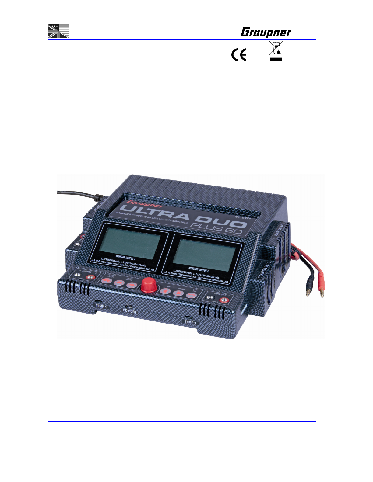
Operating Manual
ULTRA DUO PLUS 60
Order-No. 6478
No liability for printing errors. Modifications reserved.
Page 2

2/55 PAGE
PN.OF-01
Contents Page
A-1 Introduction 3
A-2 Warnings and safety notes 4
A-3 General notes on using the charger 5
A-4 Recommended charge leads/polarity 7
A-5 Charger controls /connections 8
A-6 Using the charger for the first time 8
A-7 Cleaning and maintenance 9
A-8 Notes and handling of rechargeable batteries 9
A-9 PC-Interface 12
0-1 Features 14
0-2 Main menu flow 15
0-3 Control key select flow 16
1. Memory and battery setup menu screen 17
2. Charge setup menu flow 19
3. Discharge setup screen 22
4. Cycle menu screen 24
5. Step charge menu screen 25
6. Balancer Menü 27
7. Data view screen 29
8. Tyre, battery heater / battery heater screen / POWER SUPPLY 32
9. Motor run-in screen 34
10. Config setup screen 36
11. Start select menu screen 38
12. Battery select menu screen 45
13. Operation menu screen 46
14. Error message screen 52
15. Specification 53
16. Environnemental Protection Notes 54
17. EU Conformity Declaration 54
18. Warranty 55
Page 3

3/55 PAGE
A-1. INTRODUCTION
Please study these instructions, reading them completely and attentively, before using the unit for
the first time. This will guarantee that you will be able to exploit all the facilities of your new
battery charger. The warnings and safety notes are particularly important. Please store these
instructions in a safe place, and be sure to pass them on to the new owner if you ever dispose of
the charger.
In the CHARGER you have acquired a mature product with an excellent performance. It incorporates the
latest semi-conductor technology, controlled by a high-performance RISC micro-processor, to provide
superior charging characteristics combined with simple operation and optimum reliability. These features
can normally be expected only from much more expensive units. The CHARGER represents a reliable
method of charging sintered Nickel-Cadmium (NC, Ni-Cd) packs, Nickel-Metal-Hydride (Ni-MH) batteries,
Lithium-Polymer (Li-Po), Lithium-Manganese (Li-Mn), Lithium-Ion (Li-Io) and LiFePO4 (LiFe) batteries,
and also lead-gel and lead-acid (Plumbum: Pb) batteries These sealed, gas-tight batteries have proved
excellent for our purposes in RC models. They are mechanically robust, can be used in any attitude and
are generally highly reliable. They require no special measures for storage apart from protecting the cells
from becoming deep-discharged. The CHARGER can also be used to discharge your batteries and
balance the cells in a pack.
Note
It is important always to observe the charging instructions supplied by the battery manufacturer, and to
keep to the recommended charge currents and times Do not fast-charge batteries unless the
manufacturer states expressly that they are suitable for the high currents which flow during these
processes. When charging new batteries you may also encounter problems with premature charge
termination. Whenever you wish to use a new battery it therefore makes sense to carry out a series of
monitored test charges, so that you can check that the automatic charge termination circuit works
correctly and reliably with your packs, and charges them to full capacity.
Accessories
Order No. 6444.6 Battery holder for up to seven sub-C cells with individual cell terminals for side-by-
side soldered battery packs, as generally used in competition. Required for balancing cells, e.g. Order
No. 98947.6XXL
Replacement parts
Order No. Description
6444.1 Temperature sensor for sub-C batteries, with magnet
.2 Temperature sensor without magnet, e.g. for tyre heating covers
.USB Mini-USB / PC-USB interface cable
Page 4

Page 4/55
A-2. WARNINGS AND SAFETY NOTES
• The software does not take the output current of Output 3 into account when it calculates the charge
power. This means that the charger will re-boot if the internal mains PSU is overloaded. If devices with
a relatively high current drain (more than 1 A) - such as Peltier coolers or heating covers - are
connected to the unit, we therefore recommend that you use only one of the two charge outputs, and
set the power distribution to 50% / 50%, in order to prevent overloading the internal PSU.
In this case the second output can still be used for discharging and balancing a battery.
• This product isn‘t designed for use by children under the age of 14, it isn‘t a toy!
• Protect the charger from dust, damp, rain, heat (e.g. direct sunshine) and vibration. It should only be
operated in dry indoor conditions.
• The case slots serve to cool the charger, and must not be covered or enclosed; set up the charger
with space round it, so that cooling air can circulate unhindered.
• The charger is designed to be powered by a 12 V DC car battery or power supply or 100~240V AC
main socket only. It is not permissible to modify the charger in any way. You must not connect AC
power to the DC input.
• The charger and the battery to be charged should be set up on a heat-resistant, non-inflammable
and non-conductive surface before use. Never place the charger directly on a car seat, carpet or
similar. Keep all inflammable and volatile materials well away from the charging area. Provide good
ventilation. Defective batteries can explode or burn!
• Connect the charger 12DC input directly to the car battery using the original cables and connectors
supplied. The car’s engine must be stopped all the time the CHARGER is connected to the car’s
battery. Do not recharge the car battery at any time when the CHARGER is connected to it.
• The charge output sockets and connecting leads must not be modified, and must not be inter-
connected in any way. There is a danger of short-circuit between the charge outputs and the
vehicle’s bodywork when the charger is connected to the car battery. The charge leads and
connecting leads must not be coiled up when the charger is in use. Avoid short-circuiting the charge
output or the model battery with the car bodywork. For this reason the charger must never be placed
directly on the vehicle’s bodywork.
• Never leave the charger running or connected to the car battery unsupervised.
• Only one battery may be connected to the unit for charging at any one time.
• The following types of battery must not
be connected to the charger:
- Ni-Cd / Ni-MH batteries consisting of more than 18 cells, Lithium-Ion / Li-Mn / Lithium-Polymer /
LiFePO4 (LiFe) batteries of more than 7 cells, or lead-acid batteries with a nominal voltage of more
than 12V or 24V.
- Batteries which require a different charge method from Ni-Cd, Ni-MH, Lithium or lead-acid types.
- Faulty or damaged cells or batteries.
- Batteries consisting of parallel-wired cells, or cells of different types.
- Batteries consisting of old and new cells, or cells of different makes.
Page 5

Page 5/55
- Non-rechargeable batteries (dry cells). Caution: explosion hazard!
- Batteries which are not expressly stated by the manufacturer to be suitable for the currents which
this unit delivers during the charge process.
- Packs which are already fully charged or hot, or only partially discharged.
- Batteries or cells fitted with an integral charge circuit or charge termination circuit.
- Batteries installed in a device, or which are electrically connected to other components.
• To avoid short-circuits between the banana plugs fitted to the charge leads, please always connect
the charge leads to the charger first, and only then to the battery to be charged. Reverse the
sequence when disconnecting.
• As a basic rule always check that the charge quantity is approximately the same as you expected
after
the charger has indicated that the pack is fully charged. This is a simple method of detecting a
problem reliably and in good time, should the charge process be terminated prematurely for any
reason. The likelihood of premature termination varies according to many factors, but is at its highest
with deep-discharged packs, low cell counts and particular cell types which are known to cause
problems.
• We recommend that you carry out a series of test charges to satisfy yourself that the automatic
termination circuit is working perfectly. This applies in particular when you are charging packs
consisting of a small number of cells. If the cells feature has a poorly defined voltage peak, the
charger may fail to detect the fully charged state.
• Before charging please check: have you selected the appropriate charge program for the battery?
Have you set the correct charge or discharge current? Have you set the important cut-off voltage
when charging Ni-Cd and Ni-MH packs? Are all connections firm, or is there an intermittent contact
at any point in the circuit? Please bear in mind that it can be dangerous to fast-charge batteries. For
example, if there is a brief interruption due to an intermittent contact, the result is inevitably a
malfunction such as a restart of the charge process, which would result in the pack being massively
overcharged.
• Be careful! A battery could explode or burn, if the charger does have a fault or if the user
does choose the wrong charging program and parameters.
A-3. GENERAL NOTES ON USING THE CHARGER
Charging batteries
When a battery is charged, a particular quantity of electrical energy is fed into it. The charge quantity is
calculated by multiplying charge current by charge time. The maximum permissible charge current
varies according to the battery type, and can be found in the information provided by the battery
manufacturer.
It is only permissible to charge batteries at rates higher than the standard (slow) current if they are
expressly
stated to be rapid-charge capable. The STANDARD CHARGE CURRENT is 1/10 (one
tenth) of the cells’ nominal capacity (e.g. for a 1.7 Ah pack the standard charge current is 170 mA).
Page 6

Page 6/55
• Connect the battery to be charged to the charger output sockets using a suitable charge lead (red =
positive terminal, black = negative terminal).
• Be sure to read the information provided by the battery manufacturer regarding charging methods,
and observe the recommended charge currents and charge times. Do not attempt to fast-charge
batteries unless they are expressly stated to be suitable for the high currents which this charger
delivers.
• Please bear in mind that new batteries do not reach their full capacity until they have undergone
several charge / discharge cycles. You should also be aware that the charger may terminate the
charge process prematurely when connected to new packs, and batteries which have been deep-
discharged.
• A Ni-Cd pack will normally be warm at the end of a rapid-charge process, but if you notice that one
cell of the pack is much hotter than the others, this may well indicate a fault in that cell. Such packs
could fail completely without warning, and should not be used again. Dispose of the battery safely,
preferably taking it to a toxic waste disposal centre.
• Ensure that all connectors and terminal clamps make good, sound contact. For example, if there is a
brief interruption due to an intermittent contact, the result is inevitably a malfunction such as a restart
of the charge process, which would result in the pack being massively overcharged.
• A common cause of malfunctions is the use of unsuitable charge leads. Since the charger is
incapable
of detecting the difference between a pack’s internal resistance, cable resistance and
connector transfer resistance, the first requirement if the charger is to work perfectly is that the
charge lead should be of adequate conductor cross-section and should be not be more than
30 cm long Good-quality connectors (gold-contact types) must be fitted to both ends.
• Charging transmitter batteries
A battery installed in a radio control transmitter can usually be recharged via the integral charge
socket which is fitted to the transmitter itself. Transmitter charge sockets generally include a diode
which prevents reverse current flow. This prevents damage to the transmitter electronics should the
charger be connected with reverse polarity, or if a short-circuit occurs between the bare ends of the
charge lead connectors. However, a transmitter battery protected in this way can only be charged by
the CHARGER if the diode is by-passed. Please read your transmitter operating instructions for
information on how to do this. The stated maximum charge current for the transmitter battery must
never
be exceeded. To avoid possible damage to the internal transmitter components due to
overheating and heat build-up, we recommend that the battery should be removed from the
transmitter’s battery compartment prior to charging. The transmitter must be set to „OFF“ and left in
that state for the whole period of the charge process.
Never
switch a radio control transmitter on when it is still connected to the battery charger. The
slightest interruption in the charge process may allow the charge voltage to rise to the point where it
immediately ruins the transmitter.
Never
attempt to carry out any battery discharge or battery maintenance programs via the
Page 7
Page 7/55
transmitter’s integral charge socket. The charge socket is not
suitable for this purpose.
When you set a particular current for charging, the charger only supplies that current if the value does
not exceed the unit’s technical capacity. If you set a charge current which the CHARGER cannot
deliver because it falls outside its technical limits, the unit automatically reduces the current to the
maximum possible value.
LIABILITY EXCLUSION
As manufacturers, we at GRAUPNER are not in a position to ensure that you observe the correct
methods of operation when installing, using and maintaining this charger. For this reason we are
obliged to deny all liability for loss, damage or costs which are incurred due to the incompetent or
incorrect use and operation of our products, or which are connected with such operation in any way.
Use only GRAUPNER or GM-Racing charge leads, batteries and accessories.
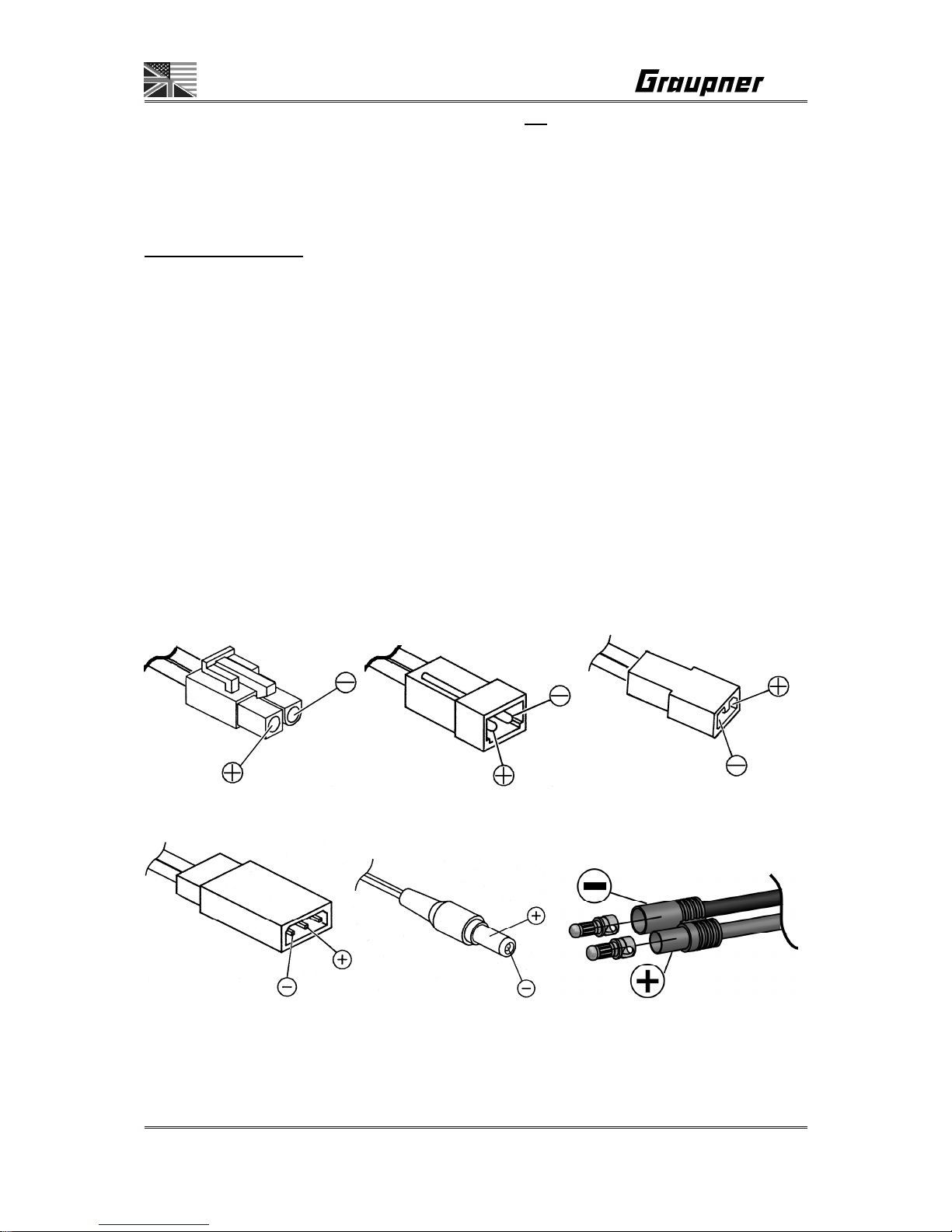
A-4. RECOMMENDED CHARGE LEADS/POLARITY
The requirements made on rechargeable batteries vary greatly according to their particular application,
and this in turn calls for different types of battery connector. Please note that connectors, connector
names and polarities may vary from one manufacturer to another. For this reason we recommend that
you always use genuine matching connectors of identical construction. The following charge leads are
suitable for battery charging with this unit:
:
JAPAN charging cable G2 charging cable BEC charging cable
Order-No. 3371 Order-No. 3011 Order-No. 3037
JR-receiver charging cable GRAUPNER/JR-transmitter charging cable G3,5 charging cable
Order-No. 3021 Order-No. 3022 Order-No. 2970.L
Be sure to use genuine charge leads fitted with cable of adequate conductor cross-section.
Page 8
Page 8/55
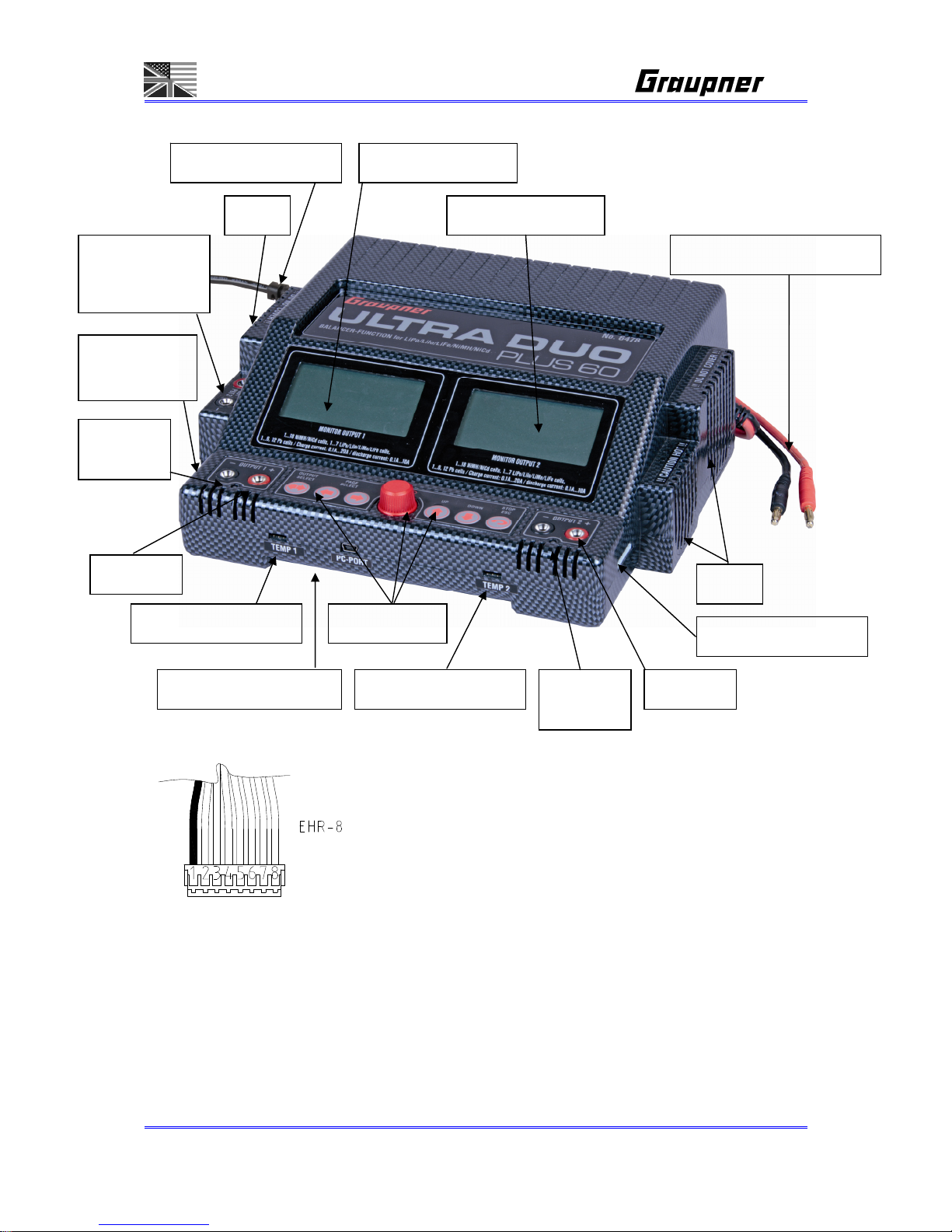
A-5. CHARGER CONTROLS / CONNECTIONS
BALANCERSTECKER:
A-6. USING THE CHARGER FOR THE FIRST TIME
Connect the charger INPUT 12V DC to a 12 V DC car battery min. 50Ah or power supply 5A-40A or
the INPUT 100~240V AC to a 100~240V AC mains socket.
Warning:
The software does not take the output current of Output 3 into account when it calculates the charge
Plug in the GRAUPNER-
BALANCER CONNECTOR
of your battery with 3-8 poles
right handed into the
BALANCER CONNECTOR of
the used OUTPUT.
Input 11…15V DC 5-40A
Input 100~240V AC Graph-LCDisplay 1
Balancer connector 2
Temperature sensor 2 PC-mini USB Interface
Temperature sensor 1
Balancer
connector 1
Fan
Fan Graph-LCDisplay 2
Output 2
Output 1
+ -
Control keys
LED
Output 1
LED
Output 2
GRAUPNER- BALANCER CONNECTOR TYPE EHR-8
PIN
1 = 0V = Ground = battery - = GND
2 = 3,7V = + cell 1
3 = 7,4V = + cell 2
4 = 11,1V = + cell 3
5 = 14,8V = + cell 4
6 = 18,5V = + cell 5
7 = 22,2V = + cell 6
8 = 25,9V = + cell 7
Output 3:
12V DC max. 5A
Page 9

Page 9/55
power. This means that the charger will re-boot if the internal mains PSU is overloaded. If devices with
a relatively high current drain (more than 1 A) - such as Peltier coolers or heating covers - are
connected to the unit, we therefore recommend that you use only one of the two charge outputs, and
set the power distribution to 50% / 50%, in order to prevent overloading the internal PSU.
In this case the second output can still be used for discharging and balancing a battery.
A-7. CLEANING AND MAINTENANCE
The charger is entirely maintenance-free in use, and requires no servicing of any kind. However, it is in
your own interests to protect the unit from dust, dirt and damp.
To clean the charger, disconnect it from the car battery and any other battery, and wipe it clean with a
dry cloth (don’t use cleaning agents!).
A-8. NOTES AND HANDLING OF RECHARGABLE BATTERIES
• Charging single Ni-Cd or Ni-MH cells, and packs consisting of 1 ... 4 cells, presents the automatic
charge termination circuit with a difficult task. The voltage peak is quite small in such cases, and it
cannot be guaranteed that the cut-off circuit will work reliably. In such conditions the automatic circuit
may not be triggered, or may not terminate the charge at the correct time. For this reason it is
important to carry out a series of monitored test charge processes with your packs in order to
establish whether the charge process is terminated reliably.
• Warm batteries offer much higher performance than cold ones, so don’t be surprised if your batteries
don’t seem so effective in the winter.
• Overcharging and deep-discharging batteries lead to irreparable damage to the cells, and
permanently reduces their maximum performance and effective capacity.
• Never store batteries for a long time in an uncharged, discharged or partially charged state. Charge
your batteries before storing them, and check their state of charge from time to time.
• When purchasing batteries we recommend that you buy good quality products exclusively. Start by
charging new packs at low rates, and work up gradually towards higher currents.
• Batteries should not be charged until shortly before use, as they are then able to deliver their best
performance.
• Do not solder directly to battery cells. The temperatures which occur during soldering can easily
damage the seals and safety valves of the cells. If this should happen, the battery may lose
electrolyte or dry out, and some of its potential performance will be lost.
• Charging any battery at high currents shortens the life expectancy of the pack. Don’t exceed the
maximum values stated by the manufacturer.
• Overcharging inevitably reduces the capacity of the battery, so do not recharge a hot pack, or one
which has already been charged.
• Charging and discharging any battery at a high current shortens the life expectancy of the pack.
Don’t exceed the maximum values stated by the manufacturer.
Page 10
Page 10/55
• Lead-acid batteries are not capable of being charged at high currents. Never exceed the maximum
charge rate stated by the battery manufacturer.
• Protect batteries from vibration, and do not subject them to mechanical stress or shock.
• Batteries can generate explosive gas (hydrogen) when on charge and when being discharged, so it is
important to provide good ventilation.
• Do not allow batteries to come into contact with water - explosion hazard.
• Never short-circuit battery contacts - explosion hazard.
• Batteries can explode or burn, if they overheat. We suggest to use a LiPo-security hard case
Order-No. 8372 with all Li-battery types and with NiCd und NiMH-batteries for charging.
• Do not open battery cells - corrosion hazard.
• It is best to „balance“, or even up the cells in Ni-Cd and Ni-MH battery packs by first discharging all
the cells separately to 0.9...1.1V and then charging up the pack.
• Please don’t be surprised if your batteries are not as willing to accept charge in winter as in summer.
The ability of a cold cell to accept and store charge is much lower than that of a warm one.
• Battery disposal
: exhausted batteries are not ordinary household waste, and you must not dispose of
them in the domestic rubbish. The retail outlet where you purchase your batteries should have a
battery recycling container for proper disposal. Trade outlets are obliged by law to accept exhausted
batteries for disposal.
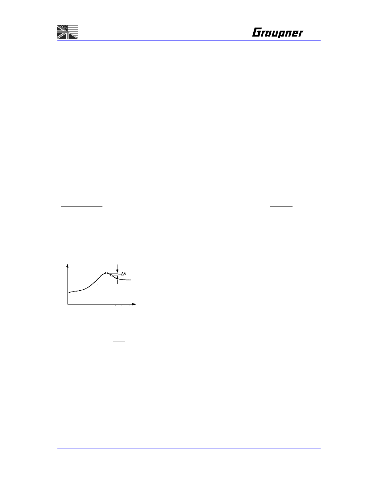
DELTA PEAK CHARGE TERMINATION for NiCd-/NiMH- Batteries:
CC-CV CHARGING METHOD FOR LiPo/LiIo/LiFe- Batteries
These programs are only suitable for charging and discharging LiFePO
4
batteries with a voltage of
3.3 V / Cell, Lithium-Ion batteries with a voltage of 3.6 V / cell, and Lithium-Polymer and Lithium-
Manganese batteries with a voltage of 3.7 V / cell. The outstanding feature of Lithium batteries is their
much higher capacity compared to other battery types. However, this important advantage is offset by
the need to adopt different handling strategies: they must be charged and discharged using specific
methods, otherwise they will be damaged, and can be dangerous. The directions in these instructions
must be observed at all times when handling these batteries. Specific information and safety notes will
also be found in the battery manufacturer’s technical information.
The automatic charge termination circuit (battery full detection)
works on the proven Delta Peak principle (also known as the
Delta-V process), which is already in use in millions of chargers.
The PEAK SENSITIVITY is shown as – delta V in the graph.
Charging Time
V
o
l
t
a
g
e
Page 11

Page 11/55
The charge process is fundamentally different to that required for Ni-Cd or Ni-MH batteries, and is
termed a constant current / constant voltage method. The charge current required varies according to
the battery capacity, and is set automatically by the charger. Lithium batteries are usually charged at
the 1C rate (1C charge rate = half capacity as charge current. Example: battery capacity 1500 mAh:
1C charge current = 1500 mA = 1.5 A).
Because some types can be charged with up to 2C or 4C charging current, the charging current and
the capacity of the battery must be set separately. When the battery on charge reaches the specific
final voltage which is appropriate to the battery type, the charger automatically reduces the charge
current in order to prevent the battery exceeding the final permissible voltage. If the battery
manufacturer states a charge current lower than the 1C rate, then the capacity (charge current) must
be reduced accordingly.
We recommend the use of the balancer connector, which ensures that your Lithium batteries
are charged optimally, and therefore increases safety and their useful life.
Problems caused by mistreating batteries:
It is very dangerous to overcharge Lithium-Ion batteries, as they tend to react by gassing, overheating
and even exploding. If the final charge voltage of 3.6 V / cell (LiFePO4), 4.1 V / cell (Lithium-Ion) or 4.2
V / cell (Lithium-Polymer and Lithium-Manganese) is exceeded by more than 1%, the lithium ions in
the cell start to change into metallic lithium. This material reacts very violently with the water in the
electrolyte, and this can result in the cell exploding. On the other hand it is also important to avoid
terminating the charge process before the final charge voltage is reached, since this reduces the
effective capacity of the Lithium-Ion cell markedly. Stopping the charge at just 0.1 V under the
threshold means a capacity loss of around 7%. Lithium batteries must not be deep-discharged, as this
leads to a rapid loss of capacity. This effect is irreversible; it is absolutely vital to avoid discharging the
batteries to below 2.5 V / cell.
Caution
: the cell type, cell capacity and cell count set on the charger must always be correct
for the battery to be charged; if you make a mistake, the battery could explode and burn! Never
connect a Lithium-based battery to the charger if it features an integral charge circuit! Always
place your Lithium batteries on a non-flammable surface for charging.
The fundamental rule is that Lithium-based batteries may ONLY
be
charged using special chargers, and the charge program must be
set up correctly in terms of final charge voltage and capacity for the
battery type in use.
Charging Time
Voltage
current
Page 12

Page 12/55
A-9. PC-INTERFACE
You can download the appropriate USB serial driver CP210x_Drivers.exe for this battery charger from
the Software Download area of www.graupner.de or www.gm-racing.de.
Install this driver first.
Connect the USB lead to the charger and to a free USB port on your PC.
PC software can be downloaded at www.graupner.de, www.gm-racing.de our www.logview.info.
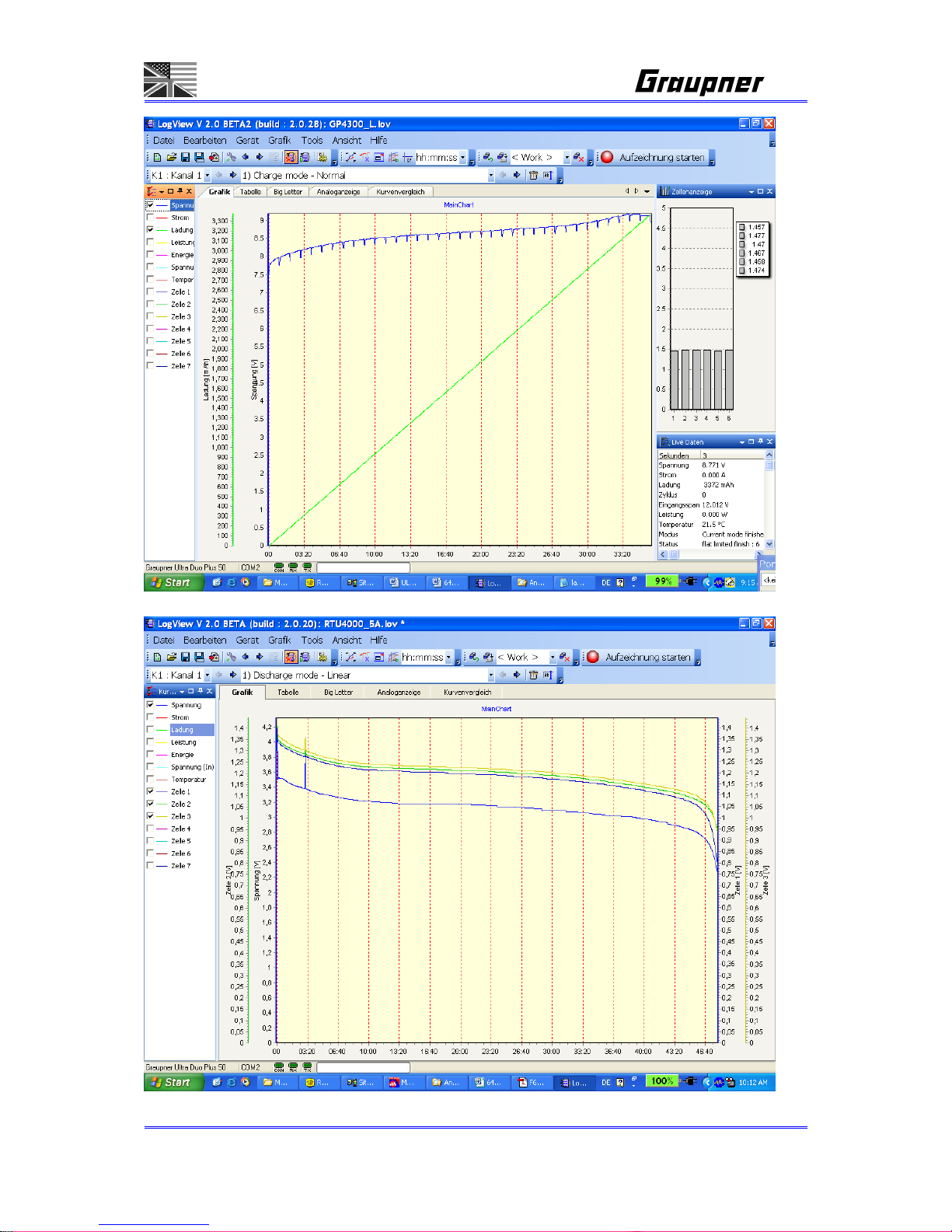
This software enables you to display battery curves and much more.
LogView - displays your serial data ...
We have been working closely with the manufacturer of the software ‘LogView’, in order to provide
optimum facilities for evaluating the data generated by our ULTRA DUO PLUS 60 battery charger.
With the help of LogView, which we recommend and support, it is possible to visualise and analyse the
serial data delivered by these chargers, and if necessary to export the data in a wide variety of forms.
The software is Donationware, and can be downloaded from the following web addresses:
www.graupner.de
or www.logview.info. If you enjoy using the software, there is a method of sending a
monetary contribution to the developer, but otherwise the program can be used free of charge.
In addition to an intuitive user-friendly interface, LogView offers the opportunity to use a wide range of
different equipment. The data received from the devices is always displayed in the same way, which
makes it much easier for the user to handle his equipment. The files generated by LogView can also
be used directly by any other user, even if he does not have actual physical access to the device in
question.
Additional software features include:
High-performance graphics engine with numerous analysis and measurement functions. Wide-
ranging options are available for adjusting the display of the curves to suit individual requirements.
Analysis functions help to investigate rechargeable batteries more thoroughly.
The curve comparison functions enable the user to display different charge and discharge processes
in graphic form. In this way it is possible in particular to assess the quality and ageing effects of
rechargeable batteries very accurately, and to compare them with other rechargeable batteries.
The object management function provides a means of storing and managing recorded data and
information relating to specific batteries.
Numerous export functions for graphs and tables allow other applications to use the data.
The label printing function provides a means of printing out labels for applying to individual battery
packs.
The integral Help system is a fast, straightforward method of obtaining information relating to the
program’s functions. If particular questions arise concerning the use of the software, or if you have
suggestions for further improvements to the LogView program, it is possible to contact the developer
directly via the LogView forum, or to exchange ideas and experiences with other users.
Page 13
Page 13/55
Page 14

Page 14/55
0-1. Features
Computer-controlled universal fast charger
With integral lightweight switch-mode mains PSU for 100 ... 240 V and 12 DC inputs. This means that the
charger is the perfect choice for all mobile applications, and also for use abroad (USA / Japan).
Two equal-value independent or dependent (CV-link mode) charge outputs
Graupner Balancer socket for 2 x 1 ... 7 NiCd / NiMH / LiPo / LiIo / LiFe cells
Sixty memories for storing all essential battery parameters
Automatic charge, discharge, capacity measurement, battery maintenance and conditioning programs for all
NiMH, NiCd, LiPo, LiIo, LiFe batteries used in modelling
Ultra-simple to operate, with clearly arranged program structure, six buttons and rotary knob button
Two high-contrast LCD screens (128 x 62) with blue backlighting: 21 x 8 characters for displaying all relevant
parameters or charge / discharge curves
Charge / discharge facilities for NiMH, NiCd, LiPo, LiIo, LiMn, LiFe or Pb (lead-acid) batteries
Delta-Peak cut-off detector for NiMH and NiCd cells with variable Delta-Peak voltage, ensuring 100% full
battery charging
Capable of charging single cells, therefore ideal for glow energizer batteries and for cell selection processes
Charges LiPo, LiIo, LiFe and lead-acid cells using constant current / constant voltage method. Declining current
curve after final charge voltage, with automatic charge termination.
Charge processes:
NiCd / NiMH: Automatic, normal, linear, GMVIS, IMPULSE, REFLEX, RE-PEAK, staged charging
LiPo / LiIo / LiFe: Automatic, CC / CV, FAST-CHG, CV-link, STORE
Special charge facility for battery storage
Balancer program
Data memory for comparing all important battery data.
Lead-acid battery charge programs with optimised charge curve, discharge facility, variable discharge current
for determining battery capacity and residual capacity.
Program for tyre heating covers
Order No. 94711 with temperature control
Motor run-in and test functions for brushed electric motors
Protected against short-circuit, overload and reversed polarity
Switchable buzzer, selectable melody
Variable safety timer
Variable max. charge capacity
Selectable language: English / German / French / Italian
Internal battery resistance display
Individual cell voltage display for 2 x 2 - 7 cells in NiCd / NiMH / Li modes
PC-USB interface for displaying battery curves on the PC screen
Ready to connect
Page 15
Page 15/55
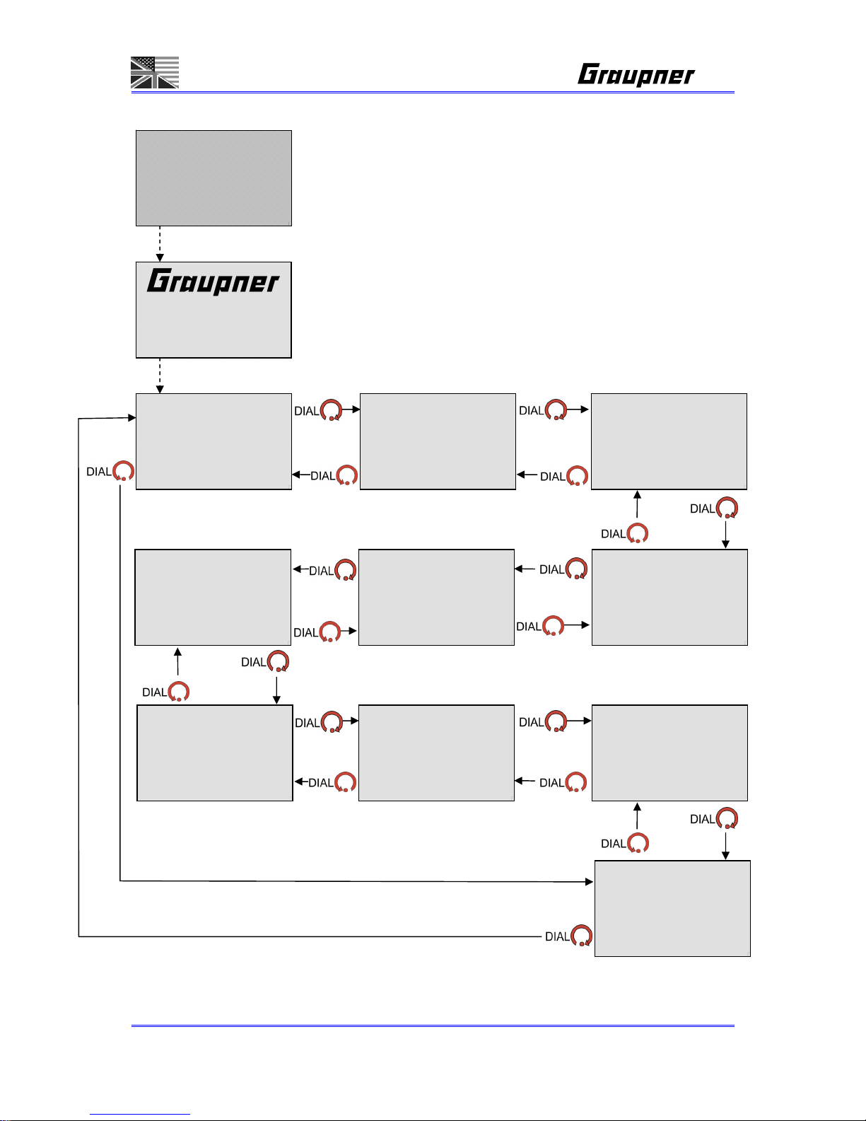
0-2. MAIN MENU FLOW
Easy to scroll up and down using the dial.
- = - - - - - - - -
CHARGE
C:00.0A d00mV/C 00°C
- - = - - - - - - -
DISCHARGE
D:00.0A 1.0V/CL 00°C
ULTRA DUO PLUS 60
GRAUPNER #6478 V1.0
USER NAME
= - - - - - - - - -
MEMORY [01]
01] NEW BATTERY NAME
- - - = - - - - - -
CYCLE
D:C>D 00T C00/D00min
- - - - = - - - - -
STEP CHARGE
D: ON d00mV/C 00°C
- - - - - = - - - -
BALANCE
0CL 0.00Vpk 0.00Va
- - - - - - = - - -
DATA VIEW
0.0Vi 0.00Vo 0.0°C
Connect the charger main plug to the input 100…240V AC
or the 4mm banana plugs to 11…15V DC, see A-6
- - - - - - - = - -
HEATER & POWER
_
_0m __0°C
_
_0m __0°C
- - - - - - - - = -
MOTOR RUN
- - - - - - - - - =
CO N F I G
00/00/2000 am00:00:00
Page 16
Page 16/55
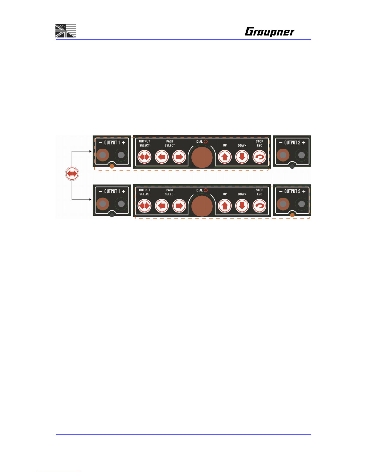
0-3. CONTROL KEY SELECT FLOW
Two LCD screens, but key control is possible for only one output.
The LCD where key control is possible is indicated by LED which flashes or is on.
In setting status, if ESC button is pressed, it directly moves to a higher menu.
In operating status, if the ESC button is pressed, operating should stop.
If OUTPUT SELECT button is pressed, OUTPUT-LED should be changed.
The OUTPUT LED is automatically changed in the following conditions.
When error occurs
If OUTPUT2 is now selected, and if error occurs in OUTPUT1, the output
should be automatically changed to OUTPUT1.
When operation is finished,
If OUTPUT2 is now selected, and if operation is finished in OUTPUT1, the
output should be automatically changed to OUTPUT1.
The function of the selected output LED.
LED should flash every one second indicating the menu status.
The LED should be ON during operating.
Page 17
Page 17/55
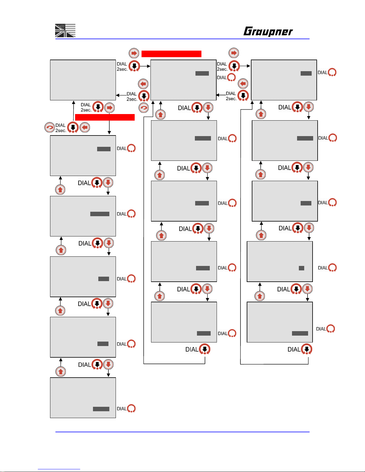
1. MEMORY AND BATTERY SETUP MENU SCREEN
= - - - - - - - - -
MEMORY [01]
01] NiMH GP 6N-4600
BATTERY SETUP <1/2>
TYPE NiMH
VOLTS _6CL _7.2V
CAPACITY _4600mAh
NEW 01/01/2008
BATTERY SETUP <1/2>
TYP E NiMH
VOLTS _6CL _7.2V
CAPACITY _4600mAh
NEW 01/01/2008
BATT NAME SETUP<2/2>
01] NiMH GP 6N-4600
^
ABCDEFGHIJKLMNOPQR
STUVWXYZabcdefghijk
lmnopqrstuvwxyz0123
456789 -.,'#_+/
ä ö ü é è
BATT NAME SETUP<2/2>
01] NiMH GP 6N-4600
^
ABCDEFGHIJKLMNOPQR
STUVWXYZabcdefghijk
lmnopqrstuvwxyz0123
456789 -.,'#_+/
ä ö ü é è
BATT NAME SETUP<2/2>
01] NiMH GP 6N-4600
^
ABCDEFGHIJKLMNOPQR
STUVWXYZabcdefghijk
lmnopqrstuvwxyz0123
456789 -.,'#_+/
ä ö ü é è
BATT NAME SETUP<2/2>
01] NiMH GP 6N-4600
^
ABCDEFGHIJKLMNOPQR
STUVWXYZabcdefghijk
lmnopqrstuvwxyz0123
456789 -.,'#_+/
ä ö ü é è
BATT NAME SETUP<2/2>
01] NiMH GP 6N-4600
^
ABCDEFGHIJKLMNOPQR
STUVWXYZabcdefghijk
lmnopqrstuvwxyz0123
456789 -.,'#_+/
ä ö ü é è
BATTERY SETUP <1/2>
TYPE NiMH
VOLTS _6CL _7.2V
CAPACITY _4600mAh
NEW 01/01/2008
...
BATTERY SETUP <1/2>
TYPE NiMH
VOLTS _6CL _7.2V
CAPACITY _4600mAh
NEW 01/01/2008
BATTERY SETUP <1/2>
TYPE NiMH
VOLTS _6CL _7.2V
CAPACITY _4600mAh
NEW 0 1 /01/2008
BATTERY SETUP <1/2>
TYPE NiMH
VOLTS _6CL _7.2V
CAPACITY _4600mAh
NEW 01/01/2008
BATT NAME SETUP<2/2>
01] NiMH GP 6N-4600
^
ABCDEFGHIJKLMNOPQR
STUVWXYZabcdefghijk
lmnopqrstuvwxyz0123
456789 -.,'#_+/
ä ö ü é è
MEMORY SELECT
01]NiMH _0.0V____0mAh
< >
01]NiMH _0.0V____0mAh
< >
MEMORY COPY
01]NiMH _0.0V____0mAh
< >
02]NiMH _0.0V____0mAh
< >
MEMORY COPY
01]NiMH _0.0V____0mAh
< >
02]NiMH _0.0V____0mAh
< >
Sure? SETUP ONLY
MEMORY COPY
01]NiMH _0.0V____0mAh
< >
02]NiMH _0.0V____0mAh
< >
Sure? SETUP+DATA
MEMORY COPY
01]NiMH _0.0V____0mAh
< >
02]NiMH _0.0V____0mAh
< >
Sure? CANCEL
Page 18

Page 18/55
1. MEMORY AND BATTERY SETUP MENU SCREEN
1-1. Memory selection
- Pressing the dial in Memory[00] then rotate the dial to select the wanted memory.
- Memory 0, 1-60 can be selected.
In any outputs, 0, 1-60 Memory can be selected and copied, but memory
room which is selected by counter output can not be selected.
- “0” Memory automatic mode can be selected at the same time in either channel 1
or channel 2.
The datas of Memory [0] are not stored into the data memory. Only the
battery type is stored.
In Automatic mode, main screens will be only shown as like order -
MEMORY CHARGE DISCHARGE DATA VIEW CONFIG
1-2. Battery selection
- In memory screen, select the memory and press “-> button”
- Set your wanted battery, cell or voltage, and capacity.
If battery type is changed, all setting parameters should be initialized, and TRACE
DAT in DAT VIEW mode is clear.
- Input the purchasing date of your battery (day/month/year)
If battery type is changed, the purchasing date on your battery should be
automatically changed to present date.
- In “0” memory, if battery type is changed then press the dial, it should move
“CHARGE SETUP”.
1-3. Battery Name Setting
- You can name your battery pack using up to total 16 letters.
1-4. Auto settings on parameters
- When battery type is changed
It should be clear to battery initial values.
- max. current:
The max. Charge or discharge current should be changed to 1C rate.
Safety timer value is automatically changed.
However, battery type and max. charge current MUST be set correctly.
Page 19
Page 19/55
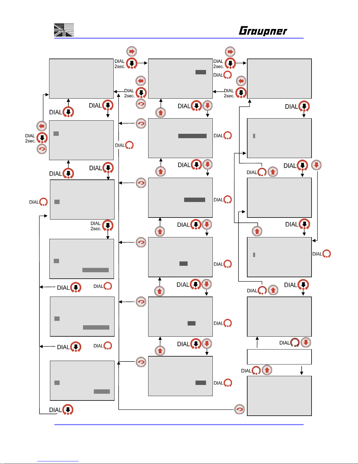
2. CHARGE SETUP MENU FLOW
- = - - - - - - - -
CHARGE
C: 4.6A ____V___ 50°C
CHARGE SETUP <1/2>
CHG CURRENT _4.6A
PEAK SENS _5mV/C
PEAK DELAY _3min
TRICKLE _AUTO
CUT-TEMP. _50°C
CHARGE SETUP <2/2>
MAX CAPACITY 125%
SAFETY TIMER _75min
FLAT CHECK _OFF
REPEAK CYCLE 1T
REPEAK DELAY _30min
CHARGE SETUP <1/1>
CHG CURRENT _2.1A
CHG VOLTAGE 4.20V/C
CUT-TEMP. 45°C
MAX CAPACITY 105%
SAFETY TIMER 140min
CHARGE SETUP <1/2>
CHG CURRENT _4.6A
PEAK SENS _5mV/C
PEAK DELAY _3min
TRICKLE _AUTO
CUT-TEMP. _50°C
CHARGE SETUP <1/2>
CHG CURRENT _4.6A
PEAK SENS _5mV/C
PEAK DELAY _3min
TRICKLE _AUTO
CUT-TEMP. _50°C
CHARGE SETUP <1/2>
CHG CURRENT _4.6A
PEAK SENS _5mV/C
PEAK DELAY _3min
TRICKLE _AUTO
CUT-TEMP. _50°C
CHARGE SETUP <1/2>
CHG CURRENT _4.6A
PEAK SENS _5mV/C
PEAK DELAY _3min
TRICKLE _AUTO
CUT-TEMP. _50°C
CHARGE SETUP <2/2>
MAX CAPACITY 125%
SAFETY TIMER _75min
FLAT CHECK _OFF
REPEAK CYCLE 1T
REPEAK DELAY _30min
CHARGE SETUP <2/2>
MAX CAPACITY 125%
SAFETY TIMER _75min
FLAT CHECK _OFF
REPEAK CYCLE 1T
REPEAK DELAY _30min
CHARGE SETUP <2/2>
MAX CAPACITY 125%
SAFETY TIMER _75min
FLAT CHECK _OFF
REPEAK CYCLE 1T
REPEAK DELAY _30min
CHARGE SETUP <1/1>
CHG CURRENT _2.1A
CHG VOLTAGE 4.20V/C
CUT-TEMP. 45°C
MAX CAPACITY 105%
SAFETY TIMER 140min
CHARGE SETUP <1/1>
CHG CURRENT _2.1A
CHG VOLTAGE 4.20V/C
CUT-TEMP. 45°C
MAX CAPACITY 105%
SAFETY TIMER 140min
CHARGE SETUP <1/1>
CHG CURRENT _2.1A
CHG VOLTAGE 4.20V/C
CUT-TEMP. 45°C
MAX CAPACITY 105%
SAFETY TIMER 140min
CHARGE SETUP <1/1>
CHG CURRENT _2.1A
CHG VOLTAGE 4.20V/C
CUT-TEMP. 45°C
MAX CAPACITY 105%
SAFETY TIMER 140min
NiMH CHARGE SETUP
LiPo CHARGE SETUP
CHARGE SETUP <2/2>
MAX CAPACITY 125%
SAFETY TIMER _75min
FLAT CHECK _OFF
REPEAK CYCLE 1T
REPEAK DELAY _30min
Page 20

Page 20/55
2. CHARGE SETUP MENU FLOW
Warning: To high settings of charging voltage (Li-batteries), charging current (all types)
or delta peak sensitivity (NiMH/NiCd) batteries can cause explosion and fire!
2-1. CHARGE CURRENT
- Set charge currents. Follow the instruction of the battery. Graupner batteries
should be charged with 0.5-1C (f. e. 6N-4200 should be charged with 4.2A).
Transmitter batteries must be charge with less then 2A. Follow the instruction of
the transmitter battery and transmitter.
2-2. PEAK SENS
WARNING! To high settings of the delta peak sensitivity can cause explosion and fire.
- Only for NiCd/NiMH. Follow the instruction of your battery or start with 3mV/Cell.
- If battery is 6cells and 3mV/C is set, the charger should finish as 3mV * 6cell =
18mV.
- In case of NIMH battery, charge can be also finished with Zero-peak.
- Set bigger peak sens values if delta-peak often happens.
- "END:DELTA-PEAK " should be shown if charge is finished with delta-peak.
- "END:ZERO-PEAK should be shown if charge is finished with ZERO-peak.
2-3. PEAK DELAY
- This function is not to detect delta peak which could happen at the initial stage of
charging and which could happen due to the chemical reaction internal battery.
Normal settings are 3-5min.
2-4. TRICKLE
- This current is to compensate battery self discharge after NICD/NiMH fast charging.
- As for Lithium battery, CV ( constant voltage ) is activated instead of trickle charge.
2-5. CUT-TEMP
- Connect the temp sensor to battery pack and when it reaches the selected temp,
charging should stop. Normal settings are 35-50°C.
- This function is likely to be used more to prevent battery pack from being
overheating rather than normal charge completion.
2-6. MAX CAPACITY
- This is to set your wanted charge percentage against the selected battery capacity.
- Set half of the battery capacity ( 50% ) for the purpose of the battery storage. Set
120-125% for fully charging of high current NiCd/NiMH batteries and 100-105% for
charging LiPo-, LiIo-, LiFe- batteries and NiMH RTU (Ready to use) batteries.
- If battery capacity is 3000mAh and if you set 10% out of the total max capacity, the
charger should stop charging at 300mAh.
- If “OFF” is set, this max capacity function is not activated.
- If charging is finished with MAX CAPACITY, “END:CAPACITY should be shown.
Page 21

Page 21/55
2-7. SAFETY TIMER
- If charging is not finished within charging time, this Safety Timer should stop
charging.
- When charge current is changed, the Safety Timer is also automatically changed.
Safety Timer per battery type is gained based on Linear charge mode
NiCd, NiMH = (Selected capacity * 60 / Selected current) * 1.5
LiIo, LiPo, LiFe, Pb = (Selected capacity * 60 / Selected current) * 2.0
Safety Timer should be “OFF” if the safety timer is bigger than 900minutes.
- Expected time can vary depending on input power or AC power (internal) in
CONFIG SETUP.
(Refer to the file “ watt limit & safe timer.xls” )
2-8. FLAT CHECK
- “END : FLAT CHECK “ : This message should be shown when the battery voltage
is not changed for a specific time during charging.
- Also, when a battery which has BIG capacity is being charged with smaller charge
current, this message could be also shown.
f. e. 4800mAh 0.1A Charge
- You can turn on or off for this FLAT CHECK function.
2-9. REPEAK CYCLE
- This is to recharge battery pack which is charged.
- This mode should be activated when it moves to “REPEAK” mode from CHARGE
PROCESS
- Since this function is to charge again the fully charged battery, this PEAK DELAY
should be automatically set to “0”. ( PEAK DELAY setting value is not charged )
- Set wanted repeak charge cycle number.
2-10. REPEAK DELAY
- Set the delay time between first repeak and second repeak.
2-11 . C HG-VO LTA G E
- This is only for lithium battery.
- Setting charging voltage can be used as battery storage.
Normally, LiPo battery is charged to 4.2V/cell, for the battery storage, it can
be charged to 3.7V/cell with CV charging.
- For charging range per battery type, please refer to “Setup Range sheet” and
battery instruction. Normal max. charging voltage settings are for:
LiFe: 3.6V/cell, LiIo: 4.1V/cell, LiMn = LiPo: 4.2V/cell. For higher cycle life
time, use 0.1V less. For storage use 0.4-0.5V less.
Page 22

Page 22/55
3. DISCHARGE MENU SCREEN
3. DISCHARGE MENU SCREEN
Warning: Deep discharging cells and too high discharge currents can destroy the
battery and can cause explosion and fire!
3-1. DSCH CURRENT
- Set wanted discharge currents. Check the battery instruction for the max.
discharge current.
3-2. DSCH CUTOFF
- Set discharge cutoff voltage per cell.
If it is set to 1.0V/Cell and its battery cell is 6cells, the discharge is finished
at 6.0V.
For NiCd/NiMH batteries the cells should be never discharged lower as
1.1V/cell.
LiFe cells should be never discharged lower as 2.5V/cell and LiPo/LiIo cells
should be never discharge lower as 3.0V/cell for the highest possible life
time.
Deep Discharge can cause capacity loss and in the worst case it can
destroy the battery and cause explosion and fire.
- Discharge is finished with smallest voltages with connecting the balancer cable the
balancing port of the charger.
Even if the cable is connected during discharging, discharge is not finished
with cell voltage.
3-3. CUT-TEMP
- Connect the temp sensor to battery, and discharge is finished when it reaches the
selected temp.
- - = - - - - - - -
DISCHARGE
D:00.0A 1.0V/CL 00°C
DISCHARGE SETUP<1/1>
DCHG CURRENT _0.0A
DCHG CUTOFF _0.0V/C
CUT-TEMP. __0°C
MAX CAPACITY __0%
MATCHED VOLT _0.00V
DISCHARGE SETUP<1/1>
DCHG CURRENT _0.0A
DCHG CUTOFF _0.0V/C
CUT-TEMP. __0°C
MAX CAPACITY __0%
MATCHED VOLT _0.00V
... 4x
Page 23

Page 23/55
- This function is likely to be used more to prevent battery pack from being
overheating rather than normal charge completion
3-4. MAX CAPACITY
- This is to set your wanted discharge percentage against the selected battery
capacity.
- If “OFF” is set, this max capacity function is not activated.
- If battery capacity is 3000mAh and if you set 10% out of the total max capacity, the
charger should stop discharging at 300mAh
3-5. MATCHED VOLT
- This is only for NICD and NIMH batteries.
- This mode should be activated when it moves to “MATCH” mode from
DISCHARGE PROCESS
- To activate this mode, balancing cable MUST be connected to the balancing port
of the charger.
- Discharge to selected voltages with selected discharge currents and match each
cell voltage.
- If the discharge cut-off voltage is set to the same voltage as the match voltage, the
discharge current will be reduced when the cut-off voltage
is reached, to hold the constant voltage at the match/cut-off voltage level.
High current competition NiMH batteries should be matched before charging.
Matching the batteries does increase the life time of the battery.
Page 24

Page 24/55
4. CYCLE MENU SCREEN
4. CYCLE MENU SCREEN
4-1. DIRECTION
- Set cycle direction.
- D:CD This mode is to first unconditionally discharge then charge to discharge
repeatedly.
4-2. CYCLE TIME
- Set the cycle repeat time number.
4-3. AF-CHG DELAY
- Set pause time before discharging after charging.
4-4. AF-DCH DELAY
- Set pause time before charging after discharging, so the battery can cool down
after discharging before the next charging starts.
- - - = - - - - - -
CYCLE
D:C>D 1T C00/D00min
CYCLE SETUP <1/1>
DIRECTION D:C>D
CYCLE TIME _0
AF-CHG DELAY _0min
AF-DCH DELAY _0min
CYCLE SETUP <1/1>
DIRECTION D:C>D
CYCLE TIME _0
AF-CHG DELAY _0min
AF-DCH DELAY _0min
CYCLE SETUP <1/1>
DIRECTION D:C>D
CYCLE TIME _0
AF-CHG DELAY _0min
AF-DCH DELAY _0min
CYCLE SETUP <1/1>
DIRECTION D:C>D
CYCLE TIME _0
AF-CHG DELAY _0min
AF-DCH DELAY _0min
Page 25

Page 25/55
5. STEP CHARGE MENU SCREEN
- - - - = - - - - -
STEP CHARGE
D: ON d00mV/C 00°C
STEP CHARGE <1/2>
D: ON d 3mV/C 50°C
400 1600 3800 4500
4.0A 8.0A 6.0A 4.0A
STEP CHARGE <2/2>
PEAK SENS _5mV/C
CUT-TEMP. _50°C
TRICKLE CHG __OFF
DISCHARGE _ON
IMPULSE CHG 1 2 3
REFLEX CHG 1 2 3
STEP CHARGE <1/2>
D: ON d 3mV/C 50°C
400 1600 3800 4500
4.0A 8.0A 6.0A 4.0A
STEP CHARGE <1/2>
D: ON d 3mV/C 50°C
400 1600 3800 4500
4.0A 8.0A 6.0A 4.0A
STEP CHARGE <1/2>
D: ON d 3mV/C 50°C
400 1600 3800 4500
4.0A 8.0A 6.0A 4.0A
STEP CHARGE <1/2>
D: ON d 3mV/C 50°C
400 1600 3800 4500
4.0A 8.0A 6.0A 4.0A
STEP CHARGE <1/2>
D: ON d 3mV/C 50°C
400 1600 3800 4500
4.0A 8.0A 6.0A 4.0A
STEP CHARGE <2/2>
PEAK SENS _5mV/C
CUT-TEMP. _50°C
TRICKLE CHG __OFF
DISCHARGE _ON
IMPULSE CHG 1 2 3
REFLEX CHG 1 2 3
STEP CHARGE <2/2>
PEAK SENS _5mV/C
CUT-TEMP. _50°C
TRICKLE CHG __OFF
DISCHARGE _ON
IMPULSE CHG 1 2 3
REFLEX CHG 1 2 3
STEP CHARGE <2/2>
PEAK SENS _5mV/C
CUT-TEMP. _50°C
TRICKLE CHG __OFF
DISCHARGE _ON
IMPULSE CHG 1 2 3
REFLEX CHG 1 2 3
STEP CHARGE <2/2>
PEAK SENS _5mV/C
CUT-TEMP. _50°C
TRICKLE CHG __OFF
DISCHARGE _ON
IMPULSE CHG 1 2 3
REFLEX CHG 1 2 3
STEP CHARGE <2/2>
PEAK SENS _5mV/C
CUT-TEMP. _50°C
TRICKLE CHG __OFF
DISCHARGE _ON
IMPULSE CHG 1 2 3
REFLEX CHG 1 2 3
... 5x
... 3x
Page 26

Page 26/55
5. STEP CHARGE MENU SCREEN
5-1. STEP CAPACITY
- This mode is only for NiMH battery, which are discharge before charging. Never charge full batteries in
this mode. Use the temperature sensor for safety reasons.
- Set wanted charge capacity in each step.
- Step charge should be finished at the fourth step based on the selected capacity in the fourth step.
Set max possible capacity which can be charged to battery.
If battery is 4300mAh and 4800mAh is charged, set 4900mAh ( 100mAh – tolerance ).
- If you want three step charging, make sure to set same capacity in 2
nd
step and 3rd step, then, it should
be jumped directly from 2
nd
step to 4th step.
- Value can be automatically set pressing the dial long as AUTO SETUP.
5-2. STEP CURRENT
- Set wanted charge current in each step.
- Value can be automatically set pressing the dial long as AUTO SETUP.
5-3. PEAK SENS
- Set peak sens voltage.
- The selected peak sens voltage is checked in each step.
5-4. CUT-TEMP
- Connect the temp sensor to battery, and charge is finished when it reaches the selected temp.
- This function is likely to be used more to prevent battery pack from being overheating rather than
normal charge completion
5-5. TRICKLE CHG
- Set additional current after fast charging.
5-6. DISCHARGE
- Set whether discharge is first activated before step charging.
- If “ON” is set, discharge is done based on selected capacity (max selected capacity) x 4C rate. It is
limited to 10.0A if X4C rate is over 10.0A.
- Step charge is basically to charge full discharged battery pack, please make sure to set “ON” always.
5-7. IMPULSE
- Set whether impulse operation is activated or no in 1
st
~ 3rd step.
- Impulse current : Selected current X 1.5 current should be delivered for 0.5 second every 3 seconds.
Ex) If 5A is set, 5.0A current for 2.5 seconds, and 7.5A for 0.5 second.
- This IMPUSE is to improve battery power.
- Battery could be damaged if excessive current with impulse operation is set.
5-8. REFLEX
- Set REFLEC operation in 1
st
step ~ 3rd step.
- REFLEX is to discharge for a very short time every one second.
Page 27

Page 27/55
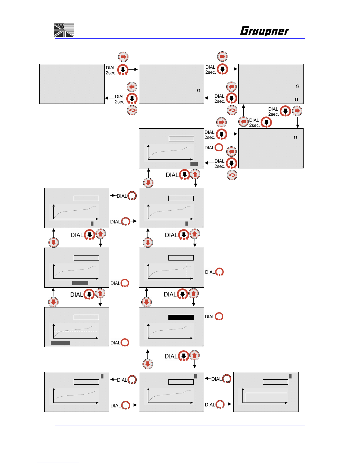
6. BALANCER MENU SCREEN
- - - - - = - - - -
BALANCE
0C 0.00VPCK 0.00Va
BALANCE <1/4>
BATT CELLS _0CELL
PACK VOLTS _0.000V
AVG VOLTS _0.000V
GAP VOLTS _0.000V
MAX NO. 0 _0.000V
MIN NO. 0 _0.000V
BALANCER <2/4>
CELL NO. 1 _0.000V
CELL NO. 2 _0.000V
CELL NO. 3 _0.000V
CELL NO. 4 _0.000V
CELL NO. 5 _0.000V
CELL NO. 6 _0.000V
CELL NO. 7 _0.000V
BALANCER 0N=0.000V
0.000Vc 0.000Vy=A CL
BALANCER 0N=0.000V
0.000Vc 0.000Vy=A CL
BALANCER 0N=0.000V
0.000Vc 0.000Vy=M CL
BALANCER 0N=0.000V
0.000Vc 0.000Vy=M CL
BALANCER 0N=0.000V
0.000Vc 0.000Vy=M CL
RESISTANCE <3/4>
CELL NO. 1 __0.0m
CELL NO. 2 __0.0m
CELL NO. 3 __0.0m
CELL NO. 4 __0.0m
CELL NO. 5 __0.0m
CELL NO. 6 __0.0m
CELL NO. 7 __0.0m
Page 28

Page 28/55
6. BALANCER MENU SCREEN
6-1. BALANCE <1/4> SCREEN
- This is to show each cell information which is connected to the balancing port of
the charger.
BATTCELLS 0CELL - Connected cell number.
PACK VOLTS 0.000V – Overall cell voltage
AVG VOLTS 0.000V – Cell average voltage
GAP VOLTS 0.000V – Between max and min voltage
MAX NO. 0 0.000V - Max cell number and voltage
MIN NO. 0 0.000V - Min cell number and voltage
6-2. CELLS VOLTAGE <2/4>SCREEN
- Showing each cell voltage
6-3. CELLS RESISTANCE <3/4>SCREEN
- Showing each cell internal resistance
6-4. BALANCE GRAPHIC
- CL, 0N : Showing the selected cell voltage
- A, M : Select Auto or Manual for Y axis of the graph
A(Auto) : If Auto is set, Vy and Vc are automatically set.
M(Manual) : If Manual is set, Vy and Vc can be manually set.
- Vy : Vy means a scale of voltage in Y axis.
- Vc : Vc means voltage of center position of Y axis.
Page 29
Page 29/55
7. DATA VIEW SCREEN
- - - - - - = - - -
DATA VIEW
0.0Vi 0.00Vo 0.0°C
DATA VIEW <1/4>
INPUT _0.000V
OUTPUT _0.000V
TEMPERATURE __0.°C
HIGH TEMP __0.0°C
RESISTANCE _0.0m
CHG TIME _0:00:00
DCHG TIME _0:00:00
CYCLE DATA _0<2/4>
FIN.00/00/07 **--:- CHG CAP ____0mAh
PEAK VOLTS _0.000V
CHG RESITANCE _0.0m
DCHG CAP ____0mAh
AVG DCHG _0.000V
DISCHG RES. _0.0m
TRACE DATA <3/4>
MIN. RES. _0.0m
LAST CHG ____0mAh
LAST DCHG ____0mAh
MAX CHG ____0mAh
MAX DCHG ____0mAh
TOTAL CHARGES __0
NEW _0/_0/2000
0:00:00 0.00V GR=V
0.000Vc 0.000V=A 0x
0:00:00 0.00V GR=V
0.000Vc 0.000V=A 0x
zoom
auto
0:00:00 0.00V GR=V
0.000Vc 0.000V=M 0x
manual
0:00:00 0.00V GR=V
0.000Vc 0.000V=M 0x
Y axis value
0:00:00 0.00V GR=V
0.000Vc 0.000V=M 0x
center value
0:00:00 0.00V GR=V
0.000Vc 0.000V=A 0x
point value
0:00:00 0.00V GR=V
0.000Vc 0.000V=A 0x
position
0:00:00 0.00V GR=V
0.000Vc 0.000V=A 0x
0:00:00 0.00A GR=I
0.000Ac 0.000A=A 0x
0:00:00 0.00°C GR=T
0.00°Cc 0.00°C=A 0x
graph type
graph type
graph type
Page 30

Page 30/55
7. DATA VIEW SCREEN
7-1. DATA VIEW <1/4>
- This is to display charge status.
INPUT 0.000V -Input Voltage
OUTPUT 0.000V -Output Voltage
TEMPERATURE 0.0`F -Temp of the temp sensor
HIGH TEMP 0.0`F -Max temp of the temp sensor
RESISTANCE 0.0m
-Battery internal resistance after
operation
CHG TIME 0:00:00 -Charge time after charging
DSCH TIME 0:00:00 -Discharge time after discharging
7-2. CYCLE DATA <2/4>
- This is to store cycle operation and various status.
- Total 11 memories ( Memory 0~10)
- Memory consists of “ROM”, even if power is OFF, the data still leaves.
- Memory “0” is the latest data, and memory 10 is the oldest data.
Data which happens after 10 times should be removed in order.
CYCLE DATA 0<2/4> - Cycle number
END.00/00/00 10:00 - Date and Time for the cycle
CHG CAP 0mAh - Charged capacity
PEAK VOLTS 0.000V - Peak voltage during charging
CHG RESITANCE 0. 0m
- Battery internal resistance at charge
DSCH CAP 0mAh - Discharged capacity
AVG DSCH 0.000V - Average voltage during discharging
DISCHG RES. 0. 0m
- Battery internal resistance at
discharge
- Memory storage
- CHARGE, DISCHARGE MODE
Data is stored to “0” memory
- CYCLE MODE
If D:C->D mode is activated for 10 times, the first discharge is
stored to “10” memory and 1~10 cycles are stored to 9~0
memories.
If CD, DC mode is activated for 10 times, 1~10 cycles are
stored to 9~0 memories.
The latest data should be stored in Memory “0”.
- STEP CHARGE
Initial discharge “1” memory storage
1
st
~ 4th STEP “0” memory storage
- REPEAK CHARGE
Since this mode is to recharge charged battery, the previous
charged data is already stored to “0” memory.
Page 31

Page 31/55
7-3. TRACE DATA <3/4>
- This is to check battery condition.
- Memory consists of “ROM”, even if power is OFF, the data still leaves.
- MEMORY setting
MIN. RES. 0. 0
- min. internal battery resistance up to
now.
LAST CHG 0mAh - Last charged capacity
LAST DSCH 0mAh - Last discharged capacity
MAX CHG 0mAh - Biggest charged capacity up to now
MAX DSCH 0mAh - Biggest discharged capacity up to
now
TOTAL CHARGES 0 - Charged number up to now
NEW 00/00/2007 - Date of using battery for the first time
7-4. OPERATION GRAPHIC
- Graph does not exist in each memory. Instead, graph is shown for last operation.
- Check graph for voltage, current, and temperature in the graph.
- Memory consists of “ROM”, even if power is OFF, the data still leaves.
0x (zoom) - It means time of X axis and 1~43 can be set.
Ex) If one screen of X axis of 1X is 2minutes, if 10x is
set, 20minutes can be shown in the screen.
The more zoom is bigger, the less accuracy of the
graph becomes. AT = AUTOZOOM
A,M(auto,manual) - Select Auto or Manual for Y axis.
A(Auto) : If Auto is set, Vy and Vc are automatically set.
M(Manual) ; If Manual is set, Vy and Vc can be man.
set
Y axis value - One scale of voltage of Y axis
center value - Voltage of center position of Y axis
position - Location for graph moving
graph type -
V – Voltage graph with indication of Vc and V
I – Current graph with indication of AC and A
T – Temperature graph with indication of Fc and F
Page 32

Page 32/55
8. TYRE HEATER / BATTERY HEATER SCREEN AND POWER SUPPLY SCREEN
- - - - - - - = - -
POWER & HEATER
__0m _
_
0°C__0m __0°C
HEATER <1/1>
SET TIME 1 __0min
SET TEMP 1 __0°C
TIME DELAY __0min
SET TIME 2 __0min
SET TEMP 2 __0.0°C
CURRENT LIMIT _0.0A
HEATER <1/1>
SET TIME 1 __0min
SET TEMP 1 __0°C
TIME DELAY __0min
SET TIME 2 __0min
SET TEMP 2 __0.0°C
CURRENT LIMIT _0.0A
HEATER <1/1>
SET TIME 1 __0min
SET TEMP 1 __0°C
TIME DELAY __0min
SET TIME 2 __0min
SET TEMP 2 __0.0°C
CURRENT LIMIT _0.0A
... 4x
POWER SUPPLY <2/2>
VOLTAGE LIMIT 12.0V
CURRENT LIMIT 5.0A
POWER SUPPLY
VOLTAGE LIMIT 12.0V
CURRENT LIMIT 5.0A
POWER RATE 50%
AC POWER USED 60.0W
_0.00V _0.0A 0.0W
POWER & HEATER START5
PROCESS [ POWER-CTL]
HEAT T1: __0min _00°C
DELAY: __0min I:_0.0A
HEAT T2: __0min _00°C
POWER & HEATER START
-- CONNECT - __ CHECK __
POWER SUPPLY
VOLTAGE LIMIT 12.0V
CURRENT LIMIT 5.0A
POWER RATE 50%
AC POWER USED 60.0W
_0.00V _0.0A 0.0W
POWER SUPPLY
VOLTAGE LIMIT 12.0V
CURRENT LIMIT 5.0A
POWER RATE 50%
AC POWER USED 60.0W
_0.00V _0.0A 0.0W
POWER SUPPLY
VOLTAGE LIMIT 12.0V
CURRENT LIMIT 5.0A
POWER RATE 50%
AC POWER USED 60.0W
_0.00V _0.0A 0.0W
Page 33

Page 33/55
8. TYRE HEATER / BATTERY HEATER SCREEN AND POWER SUPPLY SCREEN
8-1. How to use
Using tyre warmer of GM-Racing #94711 or Much More or battery heater of Much
More. Never heat tyres over 80°C and never heat batteries over 50°C.
Insert the temp sensor into the tire warmer.
Select SETUP menu
Starting this mode.
Even changed values during operation should be also stored internal memory.
8-2. SETUP
- SET TIME 1
Set operation time 1.
When it reaches the selected operation time, operation should stop.
- SET TEMP 1
Set tire temperature 1 for the best tyre additive efficiency.
Control output in accordance with temperature.
- SET DELAY
Set the delay time between heating setting 1 and setting 2, if need for better
tyre performance.
- SET TIME 2
Set operation time 2.
When it reaches the selected operation time, operation should stop.
- SET TEMP 2
Set tire temperature 2 for the best racing temperature.
Control output in accordance with temperature.
- CURRENT LIMIT
Set max currents which is delivered to tire warmer. The max. current should
be limited to 3.0A. Current is not increased any more when it reaches max
currents even if tire temperature does not match.
8-3. POWER SUPPLY
Set the voltage limit and current limit.
Connect the user to the output and then start the power supply function
with the dial button. If you start the power supply and then connect a user,
It can happen, that the power supply will switch-off and cause a reset of the
charger.
Page 34

Page 34/55
9. MOTOR RUN-IN SCREEN (Warning: only use DC brushed motors or DC fans!)
9. MOTOR RUN-IN SCREEN (Warning: only use DC brushed motors or DC fans!)
9-1. MOTOR Break-In
- This is motor brake in mode.
- Rotate the motor keeping the selected voltage.
- Set voltage and operating time.
- Set 0.1V~24V
Make sure not to exceed 12V when breaking in motor used for electric power.
12~24V range is for operating range of fan.
- - - - - - - - = -
MOTOR RUN
MOTOR BREAK-IN <1/3>
SET VOLT _0.0V
SET TIME __0m _0s
RUNTIME 000m 00s
VOLTAGE _0.00V
CURRENT _0.00A
Program Mode <2/3>
1st 2nd 3rd 4th
V>_0.0 _0.0 _0.0 _0.0
T> _0m _0m _0m _0m
D> _0m _0m _0m _0m
SPEED:0 CYCLE: _0
_0.00V _0.00A _0CYCLE
__0m00s -00000s
MOTOR Test <3/3>
Test voltage 0.0V
1st _0.0Aavg _0.0Apk
2nd _0.0Aavg _0.0Apk
3rd _0.0Aavg _0.0Apk
4th _0.0Aavg _0.0Apk
5th _0.0Aavg _0.0Apk
6th _0.0Aavg _0.0Apk
MOTOR BREAK-IN <1/3>
SET VOLT _0.0V
SET TIME __0m _0s
RUNTIME 000m 00s
VOLTAGE _0.00V
CURRENT _0.00A
MOTOR BREAK-IN <1/3>
SET VOLT _0.0V
SET TIME __0m _0s
RUNTIME 000m 00s
VOLTAGE _0.00V
CURRENT _0.00A
Program Mode <2/3>
1st 2nd 3rd 4th
V>_0.0 _0.0 _0.0 _0.0
T> _0m _0m _0m _0m
D> _0m _0m _0m _0m
SPEED:0 CYCLE: _0
_0.00V _0.00A _0CYCLE
__0m00s -00000s
Program Mode <2/3>
1st 2nd 3rd 4th
V>_0.0 _0.0 _0.0 _0.0
T> _0m _0m _0m _0m
D> _0m _0m _0m _0m
SPEED:0 CYCLE: _0
_0.00V _0.00A _0CYCLE
__0m00s -00000s
Program Mode <2/3>
1st 2nd 3rd 4th
V>_0.0 _0.0 _0.0 _0.0
T> _0m _0m _0m _0m
D> _0m _0m _0m _0m
SPEED:0 CYCLE: _0
_0.00V _0.00A _0CYCLE
__0m00s -00000s
... 11x
Page 35

Page 35/55
The motor function can only be started, if the other output is not in use!
For racing brushed motors and using the internal power supply, we
recommend to use a 1-2 Ohm resistor in series of the motor to reduce the max.
current flow.
Use voltages of max. 7.2V for 7.2V motors. Never use a higher voltage as the
motor is build for.
Higher voltages can destroy the motor and the charger. Never run brushless
motors!
9-2. Program Mode
- This mode is to program motor voltages.
- It consists of 4 steps, and user can set operation voltage, operating time and
pause time in each step.
- The meaning of “SPEED” is speed which reaches the selected voltage when step
is changed.
SPEED can be set to 1~5 and 1 is slowest and 5 is fastest. The slowest
speed is recommended for motors.
- Cycle can be set and it can be repeated in 1~4 step.
Cycle can be set to 1~10 times.
9-3. MOTOR Test
- Rotate the motor at 4.8V or 7.2V.
- Showing average currents and peak currents in each step.
- Step operation voltage
1st - 1.2V
2nd - 2.4V
3rd - 3.6V
4th - 4.8V
5th - 6.0V
6th - 7.2V
Page 36

Page 36/55
10. CONFIG SETUP SCREEN
- - - - - - - - - =
CO N F I G
00/00/2000 am00:00:00
CONFIG SETUP <2/4>
TEMP SCALE °C
BUTTON SOUND __ON
LANGUAGES _ENGLISH
PC SETUP DISABLE
SUPPLY _0.0V _0.0A
INPUT POWER [__0.0W]
TIME SETUP <3/4>
SET DATE 17/05/2007
SET TIME am11:20
SET TIME FORMAT 12h
17/05/2007 am11:20:00
USER NAME <4/4>
01] GRAUPNER GmbH
^
ABCDEFGHIJKLMNOPQR
STUVWXYZabcdefghijk
lmnopqrstuvwxyz0123
456789 -.,'#_+/
ä ö ü é è
TIME SETUP <3/4>
SET DATE 17/05/2007
SET TIME am11:20
SET TIME FORMAT 12h
17/05/2007 am11:20:00
TIME SETUP <3/4>
SET DATE 17/05/2007
SET TIME am11:20
SET TIME FORMAT 12h
17/05/2007 am11:20:00
TIME SETUP <3/4>
SET DATE 17/05/2007
SET TIME 11:20
SET TIME FORMAT 12h
17/05/2007 am11:20:00
TIME SETUP <3/4>
SET DATE 17/05/2007
SET TIME am11:20
SET TIME FORMAT 12h
17/05/2007 am11:20:00
CONFIG SETUP <2/4>
TEMP SCALE °C
BUTTON SOUND __ON
LANGUAGES _ENGLISH
PC SETUP DISABLE
SUPPLY _0.0V _0.0A
INPUT POWER [__0.0W]
CONFIG SETUP <2/4>
TEMP SCALE °C
BUTTON SOUND __ON
LANGUAGES _ENGLISH
PC SETUP DISABLE
SUPPLY _0.0V _0.0A
INPUT POWER [__0.0W]
CONFIG SETUP <2/4>
TEMP SCALE °C
BUTTON SOUND __ON
LANGUAGES _ENGLISH
PC SETUP DISABLE
SUPPLY _0.0V _0.0A
INPUT POWER [__0.0W]
CONFIG SETUP <2/4>
TEMP SCALE °C
BUTTON SOUND __ON
LANGUAGES _ENGLISH
PC SETUP DISABLE
SUPPLY _0.0V _0.0A
INPUT POWER [__0.0W]
USER NAME <4/4>
01] GRAUPNER GmbH
^
ABCDEFGHIJKLMNOPQR
STUVWXYZabcdefghijk
lmnopqrstuvwxyz0123
456789 -.,'#_+/
ä ö ü é è
...
CONFIG SETUP <1/1>
FINISH SOUND _0sec
FINISH MELODY _0
LCD CONTRAST _0
DISPLAY MOVE
MENU OUTPUT 2:
MENU OUTPUT 1:
CONFIG SETUP <1/1>
FINISH SOUND _0sec
FINISH MELODY _0
LCD CONTRAST _0
DISPLAY MOVE
... 4x
... 2x
... 2x
CONFIG SETUP <1/4>
FINISH SOUND _0sec
FINISH MELODY _0
LCD CONTRAST _0
DISPLAY MOVE
CONFIG SETUP <1/4>
FINISH SOUND _0sec
FINISH MELODY _0
LCD CONTRAST _0
DISPLAY LAST
... 3x
ZEIT KONFIG. <3/4>
DATUM 17.05.2007
UHRZEIT 17:20
ANZEIGE 24h
17.05.2007 17:20:00
Page 37

Page 37/55
10. CONFIG SETUP SCREEN
10-1. CONFIG SETUP <1/4> and <2/4>
- TEMP SCALE Can be set to either “C” or “F”
- BOTTON SOUND Button can be set to ON or OFF
Even if the button sound is OFF, the charger should beep when error occurs.
- FINISH SOUND Set operating time for finish sound.
- FINISH MELODY Select melody for finish sound.
- LCD CONTRAST Set LCD contrast
- LANGUAGES set wanted language to be operated.
- DISPLAY MOVE or LAST. Choose, if you want the moving menu or the last one
after power on.
- PC SETUP DISABLE / ACTIV = read and programm the battery memories with
the PC software.
- SUPPLY
Set power voltage and current in case of using outside DC power.
If voltage and current are set, input power is automatically calculated.
Output is limited in accordance with input power (refer to page 13 on
operation description)
10-3. TIME SETUP
- Set the Date, use the DOWN button to apply the setting. If dial is used and moved,
this should be not applied.
- Select RTC (Real Time Clock) and press the down button to confirm. This is ONLY
applied when DOWN button is pressed. If dial is used and moved, this should be not
applied.
- Time can be formatted as 12h or 24h.
Present time is shown at the bottom line.
10-4. USER NAME SETUP
- Write user name using up to 16 letters.
- This user name is shown at the initial display when the charger is connected to the
power.
Page 38

Page 38/55
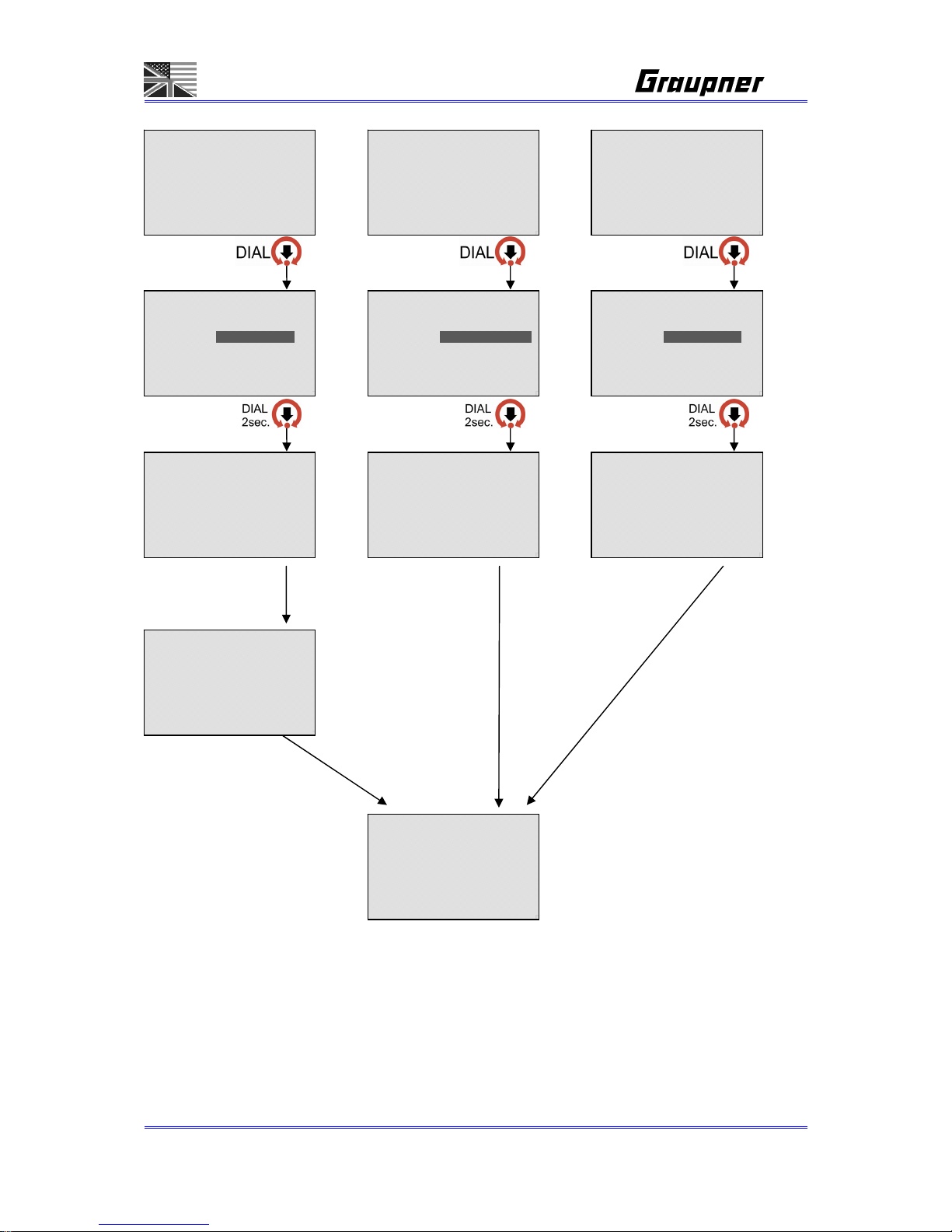
11. START SELECT MENU SCREEN
without bal. con. in Li-Mode
3sec.
5 sec. or
5 sec. or
- = - - - - - - - -
CHARGE
C: 4.6A d 5mV/C 50°C
CHARGE START 5
PROCESS [ NORMAL ]
01]NiMH 7.2V 4600mAh
C: 4.6A d 5mV/C 50°C
with bal. con.
CHARGE START
[ NiMH ] BATTERY
-- CONNECT --
__ CHECK __
- - = - - - - - - -
DISCHARGE
D:00.0A 1.0Vc/CL 00°C
- - - = - - - - - -
CYCLE
D:C>D 1T C00/D00min
- - - - = - - - - -
STEP CHARGE
D: ON d00mV/C 00°C
CHARGE START 5
DELAY TIME ____OFF
EXPECT TIME __72min
EXP.FINISH am11:12:00
01/01/2008 am10:00:00
DISCHARGE START 5
PROCESS [ NORMAL ]
01]NiMH 7.2V 4600mAh
D:10.0A 1.1Vc/CL 50°C
STEP-CHG START 5
PROCESS [STEP-CHG ]
01]NiMH 7.2V 4600mAh
___0 ___0 ___0 ___0
CYCLE START 5
CHARGE [ NORMAL ]
DISCHG [ NORMAL ]
01]NiMH 7.2V 4600mAh
D:C>D _1T C_0/D_0min
DISCHARGE START 5
DELAY TIME ____OFF
EXPECT TIME __72min
EXP.FINISH am11:12:00
01/01/2008 am10:00:00
STEP-CHG START 5
DELAY TIME ____OFF
EXPECT TIME __72min
EXP.FINISH am11:12:00
01/01/2008 am10:00:00
DISCHARGE START
[ NiMH ] BATTERY
-- CONNECT --
__ CHECK __
STEP-CHG START
[ NiMH ] BATTERY
-- CONNECT --
__ CHECK __
CYCLE START
[ NiMH ] BATTERY
-- CONNECT --
__ CHECK __
*CONNECTED CHECK* 5
[0] cells are now
Connected at the
Balancing port
.......Right?
OUTPUT [ _0.000V ]
** BALANCER **
** CONNECTION **
** ADVISED! **
*SELECT CELLS*
Select [0] cells
to be charged or
discharged.
OUTPUT [ _0.000V ]
[ NORMAL ] CHARGE
TIME _0:00:00
CAPACITY _____0mAh
VOLTAGE _0.000V
CURRENT +_0.00A
RESISTANCE __0.0m
BATT TEMP __0.0°C
3 sec.
5 sec. or
[ NORMAL ]DISCHARGE
TIME _0:00:00
CAPACITY _____0mAh
VOLTAGE _0.000V
CURRENT +_0.00A
RESISTANCE __0.0m
BATT TEMP __0.0°C
[ 4 STEP ]-CHARGE
STEP=1 [i] [r]
TIME _0:00:00
CAPACITY _____0mAh
VOLTAGE _0.000V
CURRENT +_0.00A
RESISTANCE __0.0m
BATT TEMP __0.0°C
[ NORMAL ] CHARGE
CYCLE D:C>D 0/10
TIME _0:00:00
CAPACITY _____0mAh
VOLTAGE _0.000V
CURRENT +_0.00A
RESISTANCE __0.0m
BATT TEMP __0.0°C
Page 39
Page 39/55
- - - - - = - - - -
BALANCER
0CL 0.00Vpk 0.00Va
- - - - - - - = - -
POWER & HEATER
__0m
__
0°C
_
_0m __0°C
- - - - - - - - = -
MOTOR RUN
BALANCE START 5
PROCESS [ ALONE ]
02]LiPo _0.0V ___0mAh
_0CL _0.00Vpk _0.00Va
POWER & HEATER START5
PROCESS [ POWER-CTL ]
HEAT T1: __0min _00°C
DELAY: __0min I:_0.0A
HEAT T2: __0min _00°C
MOTOR START 5
PROCESS [BREAK-IN ]
BALANCE START
[ LiPo ] BATTERY
-- CONNECT - __ CHECK __
POWER & HEATER START
-- CONNECT - __ CHECK __
MOTOR START
-- CONNECT - __ CHECK __
OPERATION SCREEN
*CONNECTED CHECK* 5
[0] cells are now
Connected at the
Balancing port
.......Right?
OUTPUT [ _0.000V ]
3 sec. 3 sec. 3 sec.
5 sec.
Page 40

Page 40/55
11. START SELECT MENU SCREEN
11-1. CHARGE START
- CHARGE FLOW
a. Pressing the dial moves to the Start mode from Charge screen.
b. Select charge process.
c. Under RESEVE TIMER “OFF”, press the dial in Reserve charge screen.
d. Check battery and cell connection.
e. Charge starts.
- CHARGE PROCESS
Make sure to select right battery type before operation.
Battery would be damaged and cause explosion and fire, if lithium
battery is charged in NiCd/NiMH mode.
If balancing cable is connected to the balancing port of the charger in
NiCD/NiMH mode, it just shows cell voltages, but it should have no
influence on charging.
The only difference is, the delta peak detection does cut-off charging,
after the first cell reaches the delta peak voltage.
a. NiCd/NiMh Battery AUTOMATIC
Battery cell and charge current are automatically gained.
Check battery internal resistance every specific time to calculate
charge current and continue to charge.
Delta-peak value is NiCd = 8mV/cell and NiMh = 6mV/cell.
Cutoff temp which is applied in charge is used.
b. LiIo/Po/Fe Battery AUTOMATIC
Battery cell and charge current are automatically gained.
For safety purpose, make sure to connect the balancing cable to
the balancing port of the charger.
Current will be fixed when it reaches constant voltage or when
auto measured current becomes smaller.
c. NORMAL
This is only for NiCD/NiMH battery.
Charge is off every one minute and measure charge voltage and
finished by delta peak.
This charge mode is good to charge old battery or when charging
cable is not stably connected
Detect charge completion every one minute and delta peak could
be slightly delayed.
d. LINEAR
Page 41

Page 41/55
This is only for NiCD/NiMH battery.
Charging has to be NOT “OFF” during charging, this charge has
to be continued.
This charge mode is very sensitive to charge cable connection,
so if connected cable is touched, charging could be finished.
Since delta peak is detected every second, it is possible to check
delta peak accurately.
It is possible to finish charging without increasing battery
temperature as ZEROpeak can be detected in this charge mode.
Charging is off 10 minutes after charging and gain battery internal
resistance.
e. GMVIS
This is only for NiCd/NiMH battery.
Charging every 6 seconds and pause every 2 seconds at the
intervals of 8 seconds.
Charging every 2 seconds and pause every 6 seconds at the final
stage of charging to prevent battery from being overheated or
venting.
f. IMPULSE
This is only for NiCd/NiMH battery. Battery power could be
improved, mainly with old batteries.
Refer to IMPULSE 5-7 above.
g. REPLEX
This is only for NiCd/NiMH battery. Battery power could be
improved, mainly with old batteries, but the life time could be
reduced.
Refer to REFLEX 5-8 above.
h. REPEAK
This is only for NiCd/NiMH battery. REPEAKING can be
dangerous, if the battery is still warm.
Refer to REPEAK CYCLE 2-8 above.
i. CC/CV
This is only for Lilo/LiPo/LiFe/Pb battery
CC to CV method. (CC = constant current, CV = constant voltage)
If balancing cable is connected to the balancing port of the
charger, charging can be very stably proceeded and finished as
the charger can use voltage measured at the balancing cable.
Page 42

Page 42/55
j. FAST-CHG
This is only for Lilo/LiPo/LiFe battery:
CC to CV method. (CC = constant current, CV = constant voltage)
Charge finished at 20% of the adjusted charge current.
Connect the balancer wires for safety reasons.
k. CV-LINK
This is only for Lilo/LiPo/LiFe.
Same capacity batteries should be used in this mode.
CV-LINK PROCESS can be selected only after balancing cable is
connected to the balancing port of the charger.
CV-LINK is to charge simultaneously, so the counterpart output
should be not being operated.
This mode is to charge individually with the battery in series.
If 7cells battery is connected in series as two packs to be used as
14 cells. This mode is to charge individual 7 cells.
If capacity is the same, 4cells in output 1 and 3cells in output 2
can be charged separately.
If charging starts in CV-LINK mode, battery connected to the
counterpart output can be also checked automatically.
Output where charge is being operated is a master output, and
the counterpart output is slave output.
All parameters in slave output are automatically gained from the
master output, so only hardware of the slave output is used.
However, cell information in slave output is gained from the cells
which are connected at the balancing port of the charger.
After CV-LINK charge is finished, only operation data of the
master output is stored in TRACE date. Which means, the data in
Slave output is not stored because hardware of slave output is
only used
l. STORE
This is only for Lilo/LiPo/LiFe battery:
CC to CV method. (CC = constant current, CV = constant voltage)
The best store voltage can be adjusted with the ‘DIAL’ button.
(push, dial and push)
(LiPo: 3,8V, LiIo: 3,7V, LiFe: 3,4V). Connect the balancer wires for
safety reasons.
Page 43

Page 43/55
11-2. DISCHARGE START
- DISCHARGE PROCESS
a. AUTOMATIC
Discharging calculating battery cell and discharge current
automatically.
The charger calculates battery internal resistance and discharge
currents every specific time.
CUTOFF VOLTAGE:
NiCd=0.9V/cell
NiMh=1.0V/cell
LiIo/Po=3.0V/cell
LiFe=2.5V/cell
Pb=1.8V/cell
Calculating and finish discharging based on above.
Cut-TEMP which is used in charging is used.
c. NORMAL
Discharge is OFF every one minute.
Average resistance is gained every one minute.
d. LINEAR
Continues to discharge without stopping.
Internal resistance is gained one time only 3 minutes after starting
discharge.
e. MATCH
refer to 3-5. MATCHED VOLT
“When each cell voltage tolerance is higher as 7mV, discharge is
checked, cell balancing is active and ‘CHK: MATCHED’ should be
shown on the screen. If the cell voltage tolerance becomes within
7mV it shows ‘END:MATCHED’.
Checking is continued and balanced (it takes time).
User can check cell tolerance and finish MATCH mode.
f. LINK
This is only for Lilo/LiPo/LiFe.
This is the same discharge method with CV-LINK charge.
11-3. CYCLE START
- PROCESS SELECT
Select wanted charge process.
Select wanted discharge process.
Page 44

Page 44/55
11-4. MOTOR START
- PROCESS SELECT
Select process to be operated.
BREAK-IN, PROGRAM, TEST
- Operation limitation
Motor operation could be only possible, if only one channel is used.
Second output can not be used at the same time.
11-5 . D ELAY T IME
- This mode is to delay time before CHARGE, DISCHARGE, STEP-CHG
This mode is only available for above modes.
- “EXPECT TIME 000min” is expected operating time.
Expected charge time is calculated based on 60W for each output if the
overall input power is 120W.
Expected time can vary in accordance with selected input power in CONFIG
SETUP.
- In order to activate delay operation, “DELAY TIMER 000min should be changed.
- This mode is based on the present time to reserve time to be finished.
When expect time is set, “EXP.FINSH am00:00:00 ( Expected finished
time ) should be shown on the screen.
EXP. FINISH = DELAY TIME + EXPECT TIME + ACTUAL TIME (RTC)
- If expected time is over 900minutes, the reserve operation screen is not shown.
- Expect time can vary in accordance with selected power or AC Power (internal) in
CONFIG SETUP.
- The expected charge time of NiMH/NiCd batteries will be 120% of the battery
capacity, except the maximum adjusted charge capacity is lower as 120%.
Page 45

Page 45/55
12. BATTERY SELECT MENU SCREEN
12. BATTERY SELECT MENU SCREEN
12-1. Balancing cable connection
- If balancing cable is not connected to the balancing port of the charger for
LiIo/LiPo/LiFe, user should set battery cell number.
If wrong cell number is set to the charger, battery could be damaged.
The present voltage is shown as “OUTPUT [ 0.000V ]”
The charger should beep every 3 seconds to indicate you should set cells.
- When balancing cable is connected to the balancing port of the charger,
The charger shows the connected cell number and user needs to recheck if
the correct cell number is shown on the screen.
If cell number shown on the screen is not correct, press the ESC button and
recheck battery cell number or selected cell number.
If selected cell number and connected cell number is not matched,
“CONNECTION ERROR” display should be shown on the screen.
- If cell number is manually set without connecting the balancing cable to the
balancing port of the charger, warn message should be shown on the
screen.
With connected balancer
connector in LiPo/LiIo/LiFe
CC/CV- or automatic mode
Wit connected balancer
connectors in LiPo/LiIo/LiFe
CV-LINK-Mode .
*CONNECTED CHECK* 5
[0] cells at OUT1 &
[0] cells at OUT2
are now connected
at each balancing
port.....Right ?
OUTPUT1 [ _0.000V ]
OUTPUT2 [ _0.000V ]
Balancer connector not connected in
LiPo/LiIo/LiFe-Mode
** BALANCER **
** CONNECTION **
** ADVISED! **
*SELECT CELLS*
Select [0] cells
to be charged or
discharged.
OUTPUT [ _0.000V ]
*CONNECTED CHECK* 5
[0] cells are now
Connected at the
Balancing port
.......Right?
OUTPUT [ _0.000V ]
Page 46

Page 46/55
13. OPERATION MENU SCREEN (LED ON)
Charge, Discharge:
Finish/END Displays:
"END:DELTA-PEAK "
"END:ZERO-PEAK "
"END:CC/CV "
"END:CUTOFF-VOLT"
"END:TEMPERATURE"
"END:CAPACITY "
"END:FLAT CHECK "
"END:TIMER "
"CHK:MATCHED "
Cycle:
[ NORMAL ] CHARGE
TIME _0:00:00
CAPACITY _____0mAh
VOLTAGE _0.000V
CURRENT +_0.00A
RESISTANCE __0.0m
BATT TEMP __0.0°C
[ NORMAL ] CHARGE
EXP.FINSH am11:12
FINISH TIME **--:- CLOCK am10:00:01
DATE 01/01/2008
POWER RATE __0%
AC POWER USED __0.0W
DATA VIEW <1/4>
INPUT _0.000V
OUTPUT _0.000V
TEMPERATURE __0.°C
HIGH TEMP __0.0°C
RESISTANCE __0.0m
CHG TIME _0:00:00
DCHG TIME _0:00:00
CYCLE DATA[_0] <2/4>
END.01/01/08 am10:00
CHG CAP ____0mAh
PEAK VOLTS _0.000V
CHG RESITANCE__0.0m
DCHG CAP ____0mAh
AVG DCHG _0.000V
DISCHG RES. __0.0m
TRACE DATA <3/4>
MIN. RES. __0.0m
LAST CHG ____0mAh
LAST DCHG ____0mAh
MAX CHG ____0mAh
MAX DCHG ____0mAh
TOTAL CHARGES __0
NEW 15/12/2007
0:00:00 0.00V GR=V
0.000Vc 0.000V=A 0x
BALANCE <1/3>
BATT CELLS _0CELL
PACK VOLTS _0.000V
AVG VOLTS _0.000V
GAP VOLTS _0.000V
MAX NO. 0 _0.000V
MIN NO. 0 _0.000V
BALANCE <2/3>
CELL NO. 1 _0.000V
CELL NO. 2 _0.000V
CELL NO. 3 _0.000V
CELL NO. 4 _0.000V
CELL NO. 5 _0.000V
CELL NO. 6 _0.000V
CELL NO. 7 _0.000V
BALANCE 0N=0.000V
0.000Vc 0.000Vy=A CL
- = - - - - - - - -
CHARGE
C: 4.6A d 5mV/C 50°C
[ NORMAL ] CHARGE
END:DELTA-PEAK
TIME _0:00:00
CAPACITY _____0mAh
VOLTAGE _0.000V
CURRENT +_0.00A
RESISTANCE __0.0m
BATT TEMP __0.0°C
Page 47

Page 47/55
D:C>D C>D D>C
Step-charge: Repeak charge:
[ NORMAL ] DISCHARGE
CYCLE D:C>D 0/10
TIME _0:00:00
CAPACITY _____0mAh
VOLTAGE _0.000V
CURRENT -_0.00A
RESISTANCE __0.0m
BATT TEMP __0.0°C
[ CYCLE ] DELAY
LEFT TIME __0m 00s
CYCLE __C>D _1/10
OUTPUT _0.000V
BATT TEMP __0.0°C
[ NORMAL ] CHARGE
CYCLE C>D 1/10
TIME _0:00:00
CAPACITY _____0mAh
VOLTAGE _0.000V
CURRENT +_0.00A
RESISTANCE __0.0m
BATT TEMP __0.0°C
[ CYCLE ] DELAY
LEFT TIME __0m 00s
CYCLE __C>D _1/10
OUTPUT _0.000V
BATT TEMP __0.0°C
[ NORMAL ] DISCHARGE
CYCLE C>D 1/10
TIME _0:00:00
CAPACITY _____0mAh
VOLTAGE _0.000V
CURRENT -_0.00A
RESISTANCE __0.0m
BATT TEMP __0.0°C
[ NORMAL ] DISCHARGE
END:CUTOFF-VOLT10/10
TIME _0:00:00
CAPACITY _____0mAh
VOLTAGE _0.000V
CURRENT -_0.00A
RESISTANCE __0.0m
BATT TEMP __0.0°C
[ NORMAL ] CHARGE
CYCLE C>D 1/10
TIME _0:00:00
CAPACITY _____0mAh
VOLTAGE _0.000V
CURRENT +_0.00A
RESISTANCE __0.0m
BATT TEMP __0.0°C
[ CYCLE ] DELAY
LEFT TIME __0m 00s
CYCLE __C>D _1/10
OUTPUT _0.000V
BATT TEMP __0.0°C
[ NORMAL ] DISCHARGE
CYCLE C>D 1/10
TIME _0:00:00
CAPACITY _____0mAh
VOLTAGE _0.000V
CURRENT -_0.00A
RESISTANCE __0.0m
BATT TEMP __0.0°C
[ NORMAL ] DISCHARGE
CYCLE D>C 1/10
TIME _0:00:00
CAPACITY _____0mAh
VOLTAGE _0.000V
CURRENT -_0.00A
RESISTANCE __0.0m
BATT TEMP __0.0°C
[ CYCLE ] DELAY
LEFT TIME __0m 00s
CYCLE __C>D _1/10
OUTPUT _0.000V
BATT TEMP __0.0°C
[ NORMAL ] DISCHARGE
END:CUTOFF-VOLT10/10
TIME _0:00:00
CAPACITY _____0mAh
VOLTAGE _0.000V
CURRENT -_0.00A
RESISTANCE __0.0m
BATT TEMP __0.0°C
[ CYCLE ] DELAY
LEFT TIME __0m 00s
CYCLE __D>C _1/10
OUTPUT _0.000V
BATT TEMP __0.0°C
[ NORMAL ] CHARGE
CYCLE D>C 1/10
TIME _0:00:00
CAPACITY _____0mAh
VOLTAGE _0.000V
CURRENT +_0.00A
RESISTANCE __0.0m
BATT TEMP __0.0°C
[ CYCLE ] DELAY
LEFT TIME __0m 00s
CYCLE __D>C _1/10
OUTPUT _0.000V
BATT TEMP __0.0°C
[ NORMAL ] CHARGE
END:DELTA-PEAK 10/10
TIME _0:00:00
CAPACITY _____0mAh
VOLTAGE _0.000V
CURRENT +_0.00A
RESISTANCE __0.0m
BATT TEMP __0.0°C
Page 48
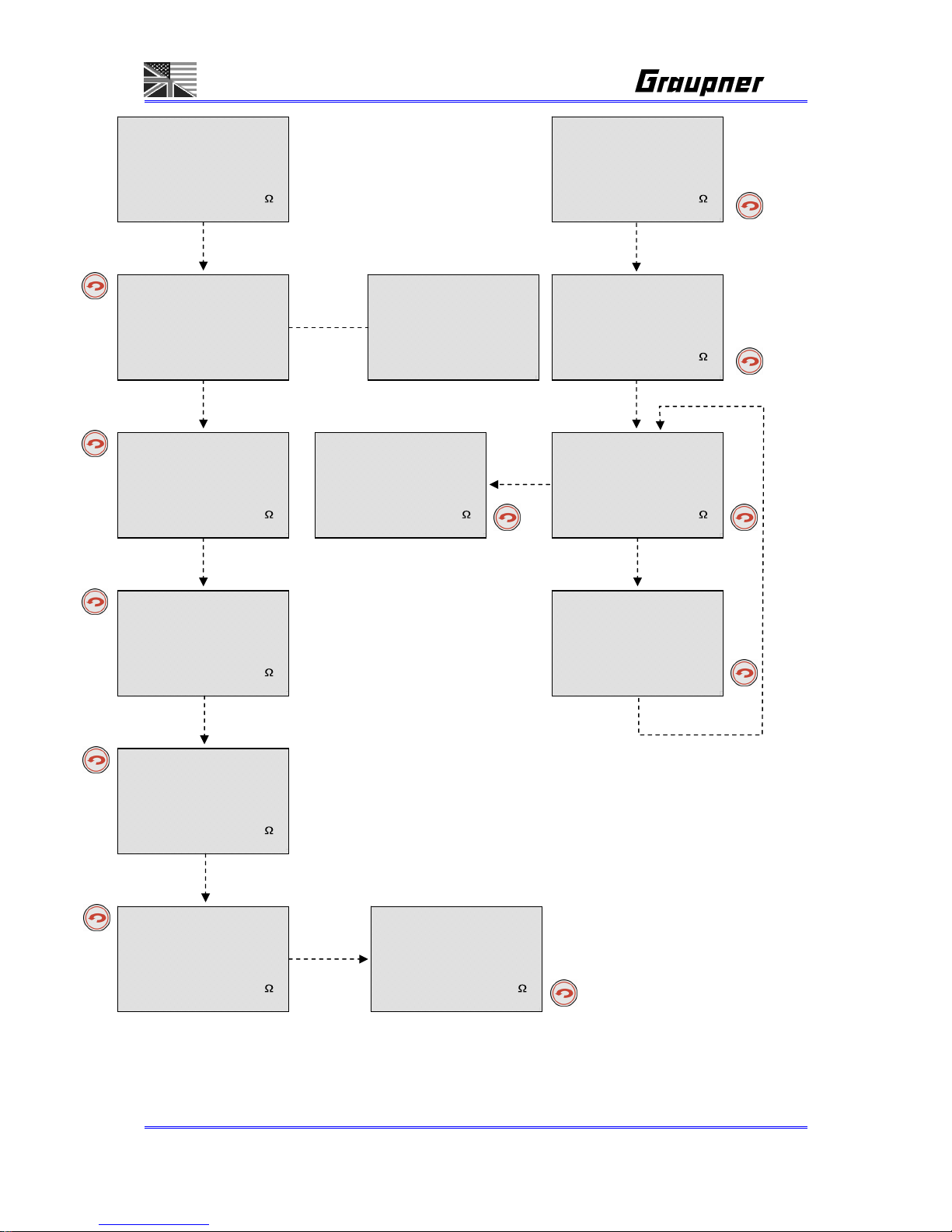
Page 48/55
REPEAK CHARGE starts here
[ 4STEP ]CHARGE
STEP=01 [i] [r]
TIME _0:00:00
CAPACITY _____0mAh
VOLTAGE _0.000V
CURRENT +_0.00A
RESISTANCE __0.0m
BATT TEMP __0.0°C
[DCHG>STEP] DELAY
LEFT TIME __0m 00s
OUTPUT _0.000V
BATT TEMP __0.0°C
[ TIMER ] DELAY
LEFT TIME __0m 00s
OUTPUT _0.000V
BATT TEMP __0.0°C
15/12/2007 am11:15:00
[PRE-DCHG] DISCHARGE
TIME _0:00:00
CAPACITY _____0mAh
VOLTAGE _0.000V
CURRENT -_0.00A
RESISTANCE __0.0m
BATT TEMP __0.0°C
[ NORMAL ] CHARGE
TIME _0:00:00
CAPACITY _____0mAh
VOLTAGE _0.000V
CURRENT +_0.00A
RESISTANCE __0.0m
BATT TEMP __0.0°C
[ REPEAK ] CHARGE
END:DELTA-PEAK 1/05
TIME _0:00:00
CAPACITY _____0mAh
VOLTAGE _0.000V
CURRENT +_0.00A
RESISTANCE __0.0m
BATT TEMP __0.0°C
[ REPEAK ] CHARGE
CYCLE NUMBER 1/05
TIME _0:00:00
CAPACITY _____0mAh
VOLTAGE _0.000V
CURRENT +_0.00A
RESISTANCE __0.0m
BATT TEMP __0.0°C
[ REPEAK ] DELAY
LEFT TIME __0m 00s
CYCLE NUMBER _0/00
OUTPUT _0.000V
BATT TEMP __0.0°C
[ 4STEP ]CHARGE
STEP=02 [i] [r]
TIME _0:00:00
CAPACITY _____0mAh
VOLTAGE _0.000V
CURRENT +_0.00A
RESISTANCE __0.0m
BATT TEMP __0.0°C
[ 4STEP ]CHARGE
STEP=03 [i] [r]
TIME _0:00:00
CAPACITY _____0mAh
VOLTAGE _0.000V
CURRENT +_0.00A
RESISTANCE __0.0m
BATT TEMP __0.0°C
[ 4STEP ]CHARGE
STEP=04 [i] [r]
TIME _0:00:00
CAPACITY _____0mAh
VOLTAGE _0.000V
CURRENT +_0.00A
RESISTANCE __0.0m
BATT TEMP __0.0°C
[ 4STEP ]CHARGE
END:DELTA-PEAK
TIME _0:00:00
CAPACITY _____0mAh
VOLTAGE _0.000V
CURRENT +_0.00A
RESISTANCE __0.0m
BATT TEMP __0.0°C
[ NORMAL ] CHARGE
END:DELTA-PEAK
TIME _0:00:00
CAPACITY _____0mAh
VOLTAGE _0.000V
CURRENT +_0.00A
RESISTANCE __0.0m
BATT TEMP __0.0°C
Page 49

Page 49/55
Balance:
Tyre Heater:
Motor Run:
TYRE HEATER <1/1>
SET TIME 1 __0min
SET TEMP 1 __0°C
DELAY TIME __0min
SET TIME 2 __0min
SET TEMP 2 __0.0°C
CURRENT LIMIT 0.0A
Program Mode <2/3>
1st 2nd 3rd 4th
V>_0.0 _0.0 _0.0 _0.0
T> _0m _0m _0m _0m
D> _0m _0m _0m _0m
SPEED:0 CYCLE: _0
_0.00V _0.00A _0CYCLE
__0m00s -00000s
MOTOR Break-In <1/3>
SET VOLT _0.00V
SET TIME __0m _0s
RUN TIME 000m 00s
VOLTAGE _0.00V
CURRENT _0.00A
MOTOR Test <3/3>
Test voltage 0.0V
1st _0.0Aavg _0.0Apk
2nd _0.0Aavg _0.0Apk
3rd _0.0Aavg _0.0Apk
4th _0.0Aavg _0.0Apk
5th _0.0Aavg _0.0Apk
6th _0.0Aavg _0.0Apk
BALANCE <1/4>
BATT CELLS _0CELL
PACK VOLTS _0.000V
AVG VOLTS _0.000V
GAP VOLTS _0.000V
MAX NO. 0 _0.000V
MIN NO. 0 _0.000V
BALANCE <2/4>
CELL NO. 1 _0.000V
CELL NO. 2 _0.000V
CELL NO. 3 _0.000V
CELL NO. 4 _0.000V
CELL NO. 5 _0.000V
CELL NO. 6 _0.000V
CELL NO. 7 _0.000V
BALANCE 0N=0.000V
0.000Vc 0.000Vy=A CL
==OPERATING==
SET TIME 1 __0min
SET TEMP 1 __0°C
DELAY TIME __0min
RUN TIME __0m _00s
TEMPERATURE __0.0°C
CURRENT _0.0A
==OPERATING==
SET TIME 1 __0min
SET TEMP 1 __0°C
>DELAY TIME __0min
RUN TIME __0m _00s
TEMPERATURE __0.0°C
CURRENT _0.0A
**COMPLETED**
SET TIME 2 __0min
SET TEMP 2 __0°C
RUN TIME __0m _00s
TEMPERATURE __0.0°C
CURRENT _0.0A
==OPERATING==
SET VOLT _0.00V
SET TIME __0m _0s
RUN TIME 000m 00s
VOLTAGE _0.00V
CURRENT _0.00A
**COMPLETED**
SET VOLT _0.00V
SET TIME __0m _0s
RUN TIME 000m 00s
VOLTAGE _0.00V
CURRENT _0.00A
==OPERATING==
1st 2nd 3rd 4th
V>_0.0 _0.0 _0.0 _0.0
T> _0m _0m _0m _0m
D> _0m _0m _0m _0m
SPEED:0 CYCLE: _0
_0.00V _0.00A _0CYCLE
__0m00s -00000s
**COMPLETED**
1st 2nd 3rd 4th
V>_0.0 _0.0 _0.0 _0.0
T> _0m _0m _0m _0m
D> _0m _0m _0m _0m
SPEED:0 CYCLE: _0
_0.00V _0.00A _0CYCLE
__0m00s -00000s
==OPERATING==
Test voltage 0.0V
1st _0.0Aavg _0.0Apk
2nd _0.0Aavg _0.0Apk
3rd _0.0Aavg _0.0Apk
4th _0.0Aavg _0.0Apk
5th _0.0Aavg _0.0Apk
6th _0.0Aavg _0.0Apk
**COMPLETED**
Test voltage 0.0V
1st _0.0Aavg _0.0Apk
2nd _0.0Aavg _0.0Apk
3rd _0.0Aavg _0.0Apk
4th _0.0Aavg _0.0Apk
5th _0.0Aavg _0.0Apk
6th _0.0Aavg _0.0Apk
==OPERATING==
SET TIME 2 __0min
SET TEMP 2 __0°C
RUN TIME __0m _00s
TEMPERATURE __0.0°C
CURRENT _0.0A
Page 50

Page 50/55
13. OPERATION MENU SCREEN
13-1. CHARGE, DISCHARGE OPERATION SCREEN
a. OPERATION SCREEN
< DISPLAY 1 >
- This is shown during CHARGE, DISCHARGE, STEP-CHARGE, CYCLE
operating. (Operation Time, capacity, voltage, current,
resistance, batt. Temp.)
- Selected current can be changed during operating.
Current can be changed in NORMAL, LINEAR, REFLEX, CC/CV,
CV-LINK charge modes.
Current can be changed in NORMAL, LINEAR, LINK discharge
mode,
Current can not be changed simultaneously in both charge or
discharge LINK mode.
< DISPLAY 2 >
- EXP.FINSH
Expected finished time is indicated.
This should be not shown in Auto, charge/discharge,
cycle, REPEAK CHG operation.
- FINISH TIME
When operation is finished and END**** is shown, time is
indicated.
This should be not shown during operation.
- CLOCK, DATE
Showing present time and date.
- CHG POWER RATE setting
Can set wattage rate of two outputs.
While charging is being proceeded in both outputs, and if wattage
is
increased in one output, the wattage of the counterpart output is
accordingly decreased.
Delta Peak could be detected due to the sudden wattage change
in NiCd/NiMH mode.
DC power used value could vary depending on using AC or DC
input power.
It is also to vary depending on the internal charge wattage.
Page 51

Page 51/55
ex1) INTERNAL POWER LIMITE = 360W
Using DC POWER 15V / 20A (300W)
If power rate is set to 50%, CH1=150W, CH2=150W can
be used in accordance with internal wattage limitation.
ex2) INTERNAL POWER LIMITE = 360W
AC INTERNAL POWER (120W)
If power rate is set to 50%, CH1=60W, CH2=60W can be
used in accordance with AC power wattage limitation.
One output takes max 250Wattage.
ex1) INTERNAL POWER LIMITE = 360W
ONE OUTPUT MAX WATTAGE = 250W
DC POWER 15V / 30A (450W)
If power rate is set to 90% in output 1, 450W X 90%=
405W can be used, but it could have max 250W due to
the wattage limitation.
b. OPERATING GRAPHIC
- It should be activated like data view menu above pos.7.
c. BALANCER GRAPHIC
- It should be activated like balance menu above pos.6.
13-2. CYCLE OPERATION SCREEN
- It shows an order of cycle operation.
13-3. STEP-CHARGE OPERATION SCREEN
- It shows an order of STEP-CHARGE
- If “DISCHARGE OFF” is set, wait for reserve time then starts charging.
- If “DISCHARGE ON” is set, discharges first then wait for reserve time.
- If “DISCHARGE ON” is set, wait for one minute then starts charging.
- Shows step number being used and status of IMPULSE and REFLEX
13-4. REPEAK CHARGE OPERATION SCREEN
- It shows an order of REPEAK CHARGE
13-5. TYRE HEATER OPERATION SCREEN
- This should be activated like the setup screen, and “==OPERATING==” should be
shown at the top line of the screen.
- All parameters can be changed during operating.
13-6. MOTOR OPERATION SCREEN
- This should be activated like the setup screen, and “==OPERATING==” should be
shown at the top line of the screen.
- All parameters can be changed during operating.
Page 52

Page 52/55
14. ERROR MESSAGE SCREEN
The error will be displayed on the LCDisplay.
[ INPUT VOLTAGE ]
* The present input
voltage is _0.00V.
* Please check the
input voltage.
* The input voltage
must be 11-15V.
[ NO BATTERY ]
* A battery is not
connected to the
ou t p u t
* Please connect the
battery to the
output then
restart !
[ REVERSE POLARITY ]
* A battery is
connected to the
output in reverse !
* Please correctly
connect the battery
to the output.
[ OPEN CIRCUIT ]
* A battery is
disconnected during
an operation.
* Please reconnect
the battery and
restart!
[ SHORT-CIRCUITED ]
* Output short circuited.
* Please check the
output.
[LOW OUTPUT VOLTAGE ]
* Output voltage is
lower than the
selected cells or
voltages
* Please select
proper cells or
voltages
[HIGH OUTPUT VOLTAGE]
* Output voltage is
higher than the
selected cells or
voltages
* Please select
proper cells or
voltages
[TEMPERATURE SENSOR ]
* A temperature
sensor is connected
in reverse or is
defective.
[ BAT. TEMP TOO LOW ]
* Battery temp is too
low to be operated!
OUTPUT _0.000V
BATT TEMP __0.0°F
[ BAT. TEMP TOO HIGH]
* Battery temp is too
high to be operated!
OUTPUT _0.000V
BATT TEMP __0.0°F
[ INTERNAL TEMP ]
* Internal temp is
too hot !
* Contact Hobby
Services if this
message appears
often.
[DATA COMMUNICATION ]
* Something is wrong
with the internal
circuit.
* Contact Hobby
Services
[ BAL.VOLTAGE HIGH ]
* Balancer cells
voltage is too
high !!
over cell is [0]
[ LINK COMMAND ]
* Link order failed !
Error occured in the
counterpart channel !
[ CONNECTION ]
* selected cells and
cells connected to
the balancing port
are different !
* Please recheck and
restart !
[ BAL.VOLTAGE LOW ]
* Balancer cells
voltage is too
lo w ! !
low cell is [0]
[ CALIRATION DATA ]
*Either calibration
data or internal
circuit might have
been damaged.
[ NO SENSOR ]
* A temp-sensor is
not connected to the
por t
* Please connect the
temp-sensor to the
port then restart !
[MOTOR OVER CURRENT ]
* Please reconnect
the motor and
restart!
[ MOTOR FUNCTION ]
* Can not start the
motor function,
because other Output
is used !
* Please stop other
Output function to
start the motor !
Page 53

Page 53/55
15. SPECIFICATION
Battery:
Charge currents / power 100 mA to 20.0 A / max. 120W overall with internal power supply
100 mA to 20.0 A / max. 2x 180 W for using both outputs or 1x 250W for
using just one output with external 11...15V DC power supply
Discharge currents / power 100 mA to 10 A / max. 80 W
Ni-Cd & Ni-MH batteries:
Cell count 1 - 18 cells
Capacity min. 0.1 Ah to 9.9 Ah
Lithium batteries:
Cell count 1-7 cells
Cell voltage 3,3 V (LiFe), 3,6 V (LiIo) / 3,7 V (LiPo/LiMn)
Capacity min. 0.1 Ah to 20.0 Ah
Lead-acid / lead-gel batteries:
Cell count 1, 2, 3, 4, 5, 6, 12 cells
Battery voltage 2, 4, 6, 8, 10, 12, 24 V
Capacity 0.1-45 Ah
General:
Operating voltage range DC input 11,0 to 15 V
Operating voltage range AC input 100 ~ 240V
Car battery required 12 V, min. 50 Ah
Mains PSU required 11-15V, min. 5-40A stabilized1)
No-load current drain approx 0.3…0.6 A
balancer connector: 1...7 NiMH/NiCd/LiPo/LiIo/LiFe cells
balancing current:: NiMH/NiCd: 0.3A, LiPo/LiIo/LiFe: 0.4A
Output 3: 12V DC max. 5A
Low-voltage cut-off approx 11,0 V
Weight approx. 2.2kg
Dimensions approx. (W x D x H) 230 x 225 x 83 mm
All data assumes a car battery voltage of 12.7 V.
The stated values are guidelines, and may vary according to battery state, temperature etc.
1)
When powered by a main PSU, the charger will only operate correctly if the PSU is suitable in terms
of voltage, stability, maximum load capacity etc. You can avoid problems by using only the PSUs
which we specifically recommend.
Page 54

Page 54/55
Environnemental Protection Notes
When this product comes to the end of its useful life, you must not dispose of it in the ordinary
domestic waste. The correct method of disposal is to take it to your local collection point for recycling
electrical and electronic equipment. The symbol shown here, which may be found on the product itself,
in the operating instructions or on the packaging, indicates that this is the case.
Individual markings indicate which materials can be recycled and re-used. You can make an important
contribution to the protection of our common environment by re-using the product, recycling the basic
materials or recycling redundant equipment in other ways.
Remove batteries from your device and dispose of them at your local collection point for batteries.
In case of R/C models, you have to remove electronic parts like servos, receiver, or speed controller
from the product in question, and these parts must be disposed of with a corresponding collection
point for electrical scrap.
If you don’t know the location of your nearest disposal centre, please enquire at your local council
office.
EU Conformity Declaration
We hereby declare that the following product:
ULTRA DUO PLUS 60; Order-No. 6478
conforms with the essential protective requirements as laid down in the directive for harmonising the
statutory directives of the member states concerning electro-magnetic interference (89/336/EWG) and
LVD (73/23/EG).
This product has been tested for electro-magnetic interference in accordance with the following norms:
EMV: EN 61000-6-1 / EN 61000-6-3, EN 55014-1 / EN 55014-2
LVD: EN 60950-1
This declaration was produced by:
Graupner GmbH & Co. KG
Henriettenstr. 94-96
73230 Kirchheim/Teck
and is valid for the manufacturer / importer of the product
73230 Kirchheim/Teck, Germany, on 20.07.10
Hans Graupner
Managing Director
Page 55

Page 55/55
Manufacturer’s declaration from Graupner GmbH & Co. KG
Content of the manufacturer’s declaration:
If material defects or manufacturing faults should arise in a product distributed by us in the Federal Republic of Germany and
purchased by a consumer (§ 13 BGB), we, Graupner GmbH & Co. KG, D-73230 Kirchheim/Teck, Germany, acknowledge the
obligation to correct those defects within the limitations described below.
The consumer is not entitled to exploit this manufacturer’s declaration if the failure in the usability of the product is due to natural
wear, use under competition conditions, incompetent or improper use (including incorrect installation) or external influences.
This manufacturer’s declaration does not affect the consumer’s legal or contractual rights regarding defects arising from the
purchase contract between the consumer and the vendor (dealer).
Extent of the guarantee
If a claim is made under guarantee, we undertake at our discretion to repair or replace the defective goods. We will not consider
supplementary claims, especially for reimbursement of costs relating to the defect (e.g. installation / removal costs) and
compensation for consequent damages unless they are allowed by statute. This does not affect claims based on legal
regulations, especially according to product liability law.
Guarantee requirements
The purchaser is required to make the guarantee claim in writing, and must enclose original proof of purchase (e.g. invoice,
receipt, delivery note) and this guarantee card. He must send the defective goods to us at his own cost, using the following
address:
Graupner GmbH & Co. KG, Service Department,
Henriettenstr. 94-96, D-73230 Kirchheim/Teck, Germany
The purchaser should state the material defect or manufacturing fault, or the symptoms of the fault, in as accurate a manner as
possible, so that we can check if our guarantee obligation is applicable.
The goods are transported from the consumer to us and from us to the consumer at the risk of the consumer.
Duration of validity
This declaration only applies to claims made to us during the claim period as stated in this declaration. The claim period is 24
months from the date of purchase of the product by the consumer from a dealer in the Federal Republic of Germany (date of
purchase). If a defect arises after the end of the claim period, or if the evidence or documents required according to this
declaration in order to make the claim valid are not presented until after this period, then the consumer forfeits any rights or
claims from this declaration.
Limitation by lapse of time
If we do not acknowledge the validity of a claim based on this declaration within the claim period, all claims based on this
declaration are barred by the statute of limitations after six months from the time of implementation; however, this cannot occur
before the end of the claim period.
Applicable law
This declaration, and the claims, rights and obligations arising from it, are based exclusively on the pertinent German Law,
without the norms of international private law, and excluding UN retail law.
 Loading...