

Page 1
GRAUPNER GmbH & Co. KG D-73230 KIRCHHEIM/TECK GERMANY
Änderungen vorbehalten! Keine Haftung für Druckfehler! Id.-Nr. 0059520 5/2009
1
zu Best.-Nr. 4217
BAUANLEITUNG
DISCUS 2CT
Für Segelflug oder Elektroantrieb ab 2 LiPo- Zellen mit 800 mAh
Es wird eine FM oder iFS- Fernsteuerung ab 2 bis 4 Funktionen benötigt
Page 2

GRAUPNER GmbH & Co. KG D-73230 KIRCHHEIM/TECK GERMANY
Änderungen vorbehalten! Keine Haftung für Druckfehler! Id.-Nr. 0059520 5/2009
2
Bitte unbedingt die folgenden Sicherheitshinweise beachten.
Sofern das Modell an eine andere Person weitergegeben wird, müssen diese
Sicherheitshinweise, bzw. die komplette Bauanleitung zur Beachtung weitergegeben werden.
Sicherheitshinweise
Für den Betrieb Ihres Flugmodells benötigen Sie eine gültige Haftpflichtversicherung, dies ist
vom Gesetzgeber so vorgeschrieben.
Vor dem Versuch der ersten Inbetriebnahme muss die gesamte Betriebs- bzw. Bauanleitung
sorgfältig gelesen werden. Sie alleine sind verantwortlich für den sicheren Betrieb Ihres RCFlugmodells. Bei Jugendlichen muss der Bau und Betrieb von einem Erwachsenen, der mit den
Gegebenheiten und möglichen Gefahren eines RC-Flugmodells vertraut ist, verantwortlich
überwacht werden.
Rechtlich gesehen, ist ein Flugmodell ein Luftfahrzeug und unterliegt entsprechenden
Gesetzen, die unbedingt eingehalten werden müssen. Die Broschüre »Modellflugrecht,
Paragrafen und mehr«, Best.-Nr. 8034.02 stellt eine Zusammenfassung dieser Gesetze dar; sie
kann auch beim Fachhandel eingesehen werden. Ferner müssen postalische Auflagen für die
Fernlenkanlage beachtet werden. Entsprechende Hinweise finden Sie in der
Bedienungsanleitung Ihrer Fernsteueranlage.
Es dürfen nur die in dem Bausatz enthaltenen Teile, sowie die ausdrücklich von uns
empfohlenen Original-Graupner-Zubehör- und Ersatzteile verwendet werden. Wird eine
Komponente der Antriebseinheit geändert, ist ein sicherer Betrieb nicht mehr gewährleistet
und es erlischt jeglicher Garantieanspruch.
Kurzschlüsse und Falschpolungen vermeiden.
Durch die hohe Energie der Batterien besteht Explosions- und Brandgefahr.
Ein RC-Flugmodell kann nur funktionsfähig sein und den Erwartungen entsprechen, wenn es
im Sinne der Bauanleitung sorgfältigst gebaut wurde. Nur ein vorsichtiger und überlegter
Umgang beim Betrieb schützt vor Personen- und Sachschäden. Niemand würde sich in ein
Segelflugzeug setzen und - ohne vorausgegangene Schulung - versuchen, damit zu fliegen.
Erfolgreiches Modellfliegen erfordert ebenso eine Ausbildungs-bzw. Übungsphase.
Der Hersteller hat jedoch keine Möglichkeit, den Bau und den Betrieb eines RC-Flugmodells zu
beeinflussen. Deshalb wird hiermit auf die Gefahren nachdrücklich hingewiesen und jede
Haftung dafür abgelehnt.
Bitte wenden Sie sich dazu an erfahrene Modellflieger, an Vereine oder Modellflugschulen.
Ferner sei auf den Fachhandel und die einschlägige Fachpresse verwiesen. Am besten als
Club-Mitglied auf zugelassenem Modellflugplatz fliegen.
Klebstoffe enthalten Inhaltsstoffe, die unter Umständen gesundheitsschädlich sein können.
Beachten Sie daher unbedingt auch die entsprechenden Hinweise und Warnungen der
Hersteller.
Der Betreiber muss im Besitz seiner vollen körperlichen und geistigen Fähigkeiten sein. Wie
beim Autofahren, ist der Betrieb des Flugmodells unter Alkohol oder Drogeneinwirkung nicht
erlaubt.
Informieren Sie Passanten und Zuschauer vor der Inbetriebnahme über Gefahren, die von
Ihrem Modell ausgehen und ermahnen Sie diese, sich in ausreichendem Schutzabstand
aufzuhalten.
Stets mit dem notwendigen Sicherheitsabstand zu Personen oder Hindernissen fliegen, nie
Personen überfliegen oder auf sie zufliegen!
Modellflug darf nur bei Außentemperaturen von - 5º C bis + 35º C betrieben werden. Extreme
Temperaturen können zu Veränderungen der Batteriekapazität, der Werkstoffeigenschaften
sowie z. B. zu mangelhaften Klebeverbindungen u.s.w. führen.
Page 3
GRAUPNER GmbH & Co. KG D-73230 KIRCHHEIM/TECK GERMANY
Änderungen vorbehalten! Keine Haftung für Druckfehler! Id.-Nr. 0059520 5/2009
3
Jeder Modellflieger hat sich so zu verhalten, dass die öffentliche Sicherheit, insbesondere
andere Personen und Sachen, sowie der Ablauf des Modellflugbetriebs nicht gefährdet oder
gestört wird.
Das Flugmodell niemals in der Nähe von Hochspannungsleitungen, Industriegeländen, in
Wohngebieten, öffentlichen Straßen, Schulhöfen oder Spielplätzen usw. fliegen lassen.
Überprüfung vor dem Start
Vor jedem Einsatz korrekte Funktion überprüfen. Dazu den Sender einschalten, ebenso den
Empfänger. Senderantenne ausziehen, kontrollieren ob alle Ruder in Neutrallage stehen,
einwandfrei funktionieren und seitenrichtig ausschlagen. Diese Überprüfung bei laufendem
Motor wiederholen, während ein Helfer das Modell festhält.
Beim erstmaligen Steuern eines Flugmodells ist es von Vorteil, wenn ein erfahrener Helfer bei
der Überprüfung und den ersten Flügen zur Seite steht.
Warnungen müssen unbedingt beachtet werden. Sie beziehen sich auf Dinge und Vorgänge,
die bei einer Nichtbeachtung zu schweren - in Extremfällen tödlichen Verletzungen oder
bleibenden Schäden führen können.
Luftschrauben die durch einen Motor angetrieben werden, stellen eine ständige
Verletzungsgefahr dar. Sie dürfen mit keinem Körperteil berührt werden! Eine schnell drehende
Luftschraube kann z. B. einen Finger einschneiden!
Sich niemals in oder vor der Drehebene von Luftschrauben aufhalten! Es könnte sich doch
einmal ein Teil davon oder die komplette Luftschraube lösen und mit hoher Geschwindigkeit
und viel Energie wegfliegen und Sie oder Dritte treffen. Dies kann u. U. zu schweren
Verletzungen führen . Darauf achten, dass kein sonstiger Gegenstand mit einer laufenden
Luftschraube in Berührung kommt!
Die Blockierung der Luftschraube, durch irgendwelche Teile, muss ausgeschlossen sein.
Überprüfen Sie vor jeder Inbetriebnahme das Modell und alle an ihm gekoppelten Teile (z. B.
Luftschrauben, RC-Teile usw.) auf festen Sitz und mögliche Beschädigungen. Das Modell darf
erst nach Beseitigung aller Mängel in Betrieb genommen werden.
Vergewissern Sie sich, dass die verwendete Sender- Frequenz frei ist. Erst dann den Sender
einschalten! Funkstörungen, verursacht durch Unbekannte, können stets ohne Vorwarnung
auftreten! Das Modell ist dann steuerlos und unberechenbar! Fernlenkanlage nicht
unbeaufsichtigt lassen, um ein Betätigen durch Dritte zu verhindern.
Elektromotor nur einschalten, wenn nichts im Drehbereich der Luftschraube ist. Nicht
versuchen, die laufende Luftschraube anzuhalten. Elektromotor mit Luftschraube nur im
eingebauten Zustand betreiben.
Die Fluglage des Modells muss während des gesamten Fluges immer eindeutig erkennbar sein,
um immer ein sicheres Steuern und Ausweichen zu gewährleisten. Machen sich während des
Fluges Funktionsbeeinträchtigungen/Störungen bemerkbar, muss aus Sicherheitsgründen
sofort die Landung eingeleitet werden. Sie haben anderen Luftfahrzeugen stets auszuweichen.
Start- und Landeflächen müssen frei von Personen und sonstigen Hindernissen sein.
Immer auf vollgeladene Batterien achten, da sonst keine einwandfreie Funktion der RC-Anlage
gewährleistet ist.
Niemals heiß gewordene, defekte oder beschädigte Batterien verwenden. Es sind stets die
Gebrauchsvorschriften des Batterieherstellers zu beachten.
Vor jedem Flug eine Überprüfung der kompletten RC-Anlage, sowie des Flugmodells, auf volle
Funktionstüchtigkeit und Reichweite durchführen.
Dabei ist zu beachten, dass bei der Inbetriebnahme die Motorsteuerfunktion am Sender immer
zuerst in AUS-Stellung gebracht wird. Danach Sender und dann erst Empfangsanlage
Page 4

GRAUPNER GmbH & Co. KG D-73230 KIRCHHEIM/TECK GERMANY
Änderungen vorbehalten! Keine Haftung für Druckfehler! Id.-Nr. 0059520 5/2009
4
einschalten, um ein unkontrolliertes Anlaufen des Elektromotors zu vermeiden. Gleichfalls gilt
immer zuerst Empfangsanlage ausschalten, danach erst den Sender.
Überprüfen Sie, dass die Ruder sich entsprechend der Steuerknüppelbetätigung bewegen.
Nach Gebrauch die Batterie aus dem Modell nehmen und nur im entladenen Zustand für Kinder
unzugänglich, bei ca. + 5º bis + 25º C aufbewahren.
Mit diesen Hinweisen soll auf die vielfältigen Gefahren hingewiesen werden, die durch
unsachgemäße und verantwortungslose Handhabung entstehen können. Richtig und
gewissenhaft betrieben ist Modellflug eine kreative, lehrreiche und erholsame
Freizeitgestaltung.
Herstellererklärung:
Sollten sich Mängel an Material oder Verarbeitung an einem von uns in der Bundesrepublik
Deutschland vertriebenen, durch einen Verbraucher (§ 13 BGB) erworbenen Gegenstand
zeigen, übernehmen wir, die Fa. Graupner GmbH & Co KG, D-73230 Kirchheim/Teck im
nachstehenden Umfang die Mängelbeseitigung für den Gegenstand.
Rechte aus dieser Herstellererklärung kann der Verbraucher nicht geltend machen, wenn die
Beeinträchtigung der Brauchbarkeit des Gegenstandes auf natürlicher Abnutzung, Einsatz
unter Wettbewerbsbedingungen, unsachgemäßer Verwendung (einschließlich Einbau) oder
Einwirkung von außen beruht.
Diese Herstellererklärung lässt die gesetzlichen oder vertraglich eingeräumten
Mängelansprüche und –rechte des Verbrauchers aus dem Kaufvertrag gegenüber seinem
Verkäufer (Händler) unberührt.
Umfang der Garantieleistung
Im Garantiefall leisten wir nach unserer Wahl Reparatur oder Ersatz der mangelbehafteten
Ware. Weitergehende Ansprüche, insbesondere Ansprüche auf Erstattung von Kosten im
Zusammenhang mit dem Mangel (z.B. Ein-/Ausbaukosten) und der Ersatz von Folgeschäden
sind – soweit gesetzlich zugelassen – ausgeschlossen. Ansprüche aus gesetzlichen
Regelungen, insbesondere nach dem Produkthaftungsgesetz, werden hierdurch nicht berührt.
Voraussetzung der Garantieleistung
Der Käufer hat den Garantieanspruch schriftlich unter Beifügung des Originals des Kaufbelegs
(z.B. Rechnung, Quittung, Lieferschein) und dieser Garantiekarte geltend zu machen. Er hat
zudem die defekte Ware auf seine Kosten an die o.g. Adresse einzusenden.
Der Käufer soll dabei den Material- oder Verarbeitungsfehler oder die Symptome des Fehlers
so konkret benennen, dass eine Überprüfung unserer Garantiepflicht möglich wird.
Der Transport des Gegenstandes vom Verbraucher zu uns als auch der Rücktransport erfolgen
auf Gefahr des Verbrauchers.
Gültigkeitsdauer
Diese Erklärung ist nur für während der Anspruchsfrist bei uns geltend gemachten Ansprüche
aus dieser Erklärung gültig. Die Anspruchsfrist beträgt 24 Monate ab Kauf des Gerätes durch
den Verbraucher bei einem Händler in der Bundesrepublik Deutschland (Kaufdatum). Werden
Mängel nach Ablauf der Anspruchsfrist angezeigt oder die zur Geltendmachung von Mängeln
nach dieser Erklärung geforderten Nachweise oder Dokumente erst nach Ablauf der
Anspruchsfrist vorgelegt, so stehen dem Käufer keine Rechte oder Ansprüche aus dieser
Erklärung zu.
Verjährung
Soweit wir einen innerhalb der Anspruchsfrist ordnungsgemäß geltend gemachten Anspruch
aus dieser Erklärung nicht anerkennen, verjähren sämtliche Ansprüche aus dieser Erklärung in
6 Monaten vom Zeitpunkt der Geltendmachung an, jedoch nicht vor Ende der Anspruchsfrist.
Anwendbares Recht
Auf diese Erklärung und die sich daraus ergebenden Ansprüche, Rechte und Pflichten findet
ausschließlich das materielle deutsche Recht ohne die Normen des Internationalen
Privatrechts sowie unter Ausschluss des UN-Kaufrechts Anwendung.
Page 5

GRAUPNER GmbH & Co. KG D-73230 KIRCHHEIM/TECK GERMANY
Änderungen vorbehalten! Keine Haftung für Druckfehler! Id.-Nr. 0059520 5/2009
5
Allgemeines
Das Modell DISCUS 2CT ist ein vorbildähnliches RC- Flugmodell, das hervorragende
Flugleistungen erzielt. Bitte beachten Sie, dass das Modell in drei Versionen gebaut
werden kann. Für jede Version sind unterschiedliche Zubehörteile erforderlich.
Entscheiden Sie sich vor Baubeginn für eine Version, da ein nachträglicher Umbau
nicht mehr möglich ist. Aus Sicherheitsgründen darf das Fluggewicht nicht über 500 g
liegen.
1. Segelversion
2. Segelversion für F- Schlepp
3. Elektroversion*
*
Diese Version ist besonders empfehlenswert, da der Motoraufsatz in Sekundenschnelle abgezogen werden kann und
das Modell dann auch als reines Segelflugmodell eingesetzt werden kann.
RC-Zubehör (nicht enthalten)
Zur Steuerung des Modells sind FM-Fernsteueranlagen wie z. B. MX-12 bis MC-24
bzw. iFS- Fernsteuersysteme geeignet. Weitere Informationen über RC-Zubehörteile
sind dem GRAUPNER Hauptkatalog FS zu entnehmen
FM Fernlenkset MX-12 FM 35* Best.-Nr. 4722
*Frequenzband 35 MHz in Deutschland ausschließlich für Flugmodelle reserviert.
Senderladekabel Best.-Nr. 3022
Empfängerladekabel (nur für Segelversionen) Best.-Nr. 3021
Ladekabel mit BEC Stecker (nur für Elektroversion) Best.-Nr. 3037
Ladegerät ULTRAMAT 8 Best.-Nr. 6411
Servo C131 (2 Stück erforderlich) Best.-Nr. 7121
Trimmgewicht Best.-Nr. 536
Zubehör für Segelversionen (nicht enthalten)
Schleppkupplung
Best.-Nr.
Empfängerbatterie
Best.-Nr.
Servo für Schleppkupplung
Best.-Nr.
Innen Ø 6mm
7890.1
GRAUPNER
4N-600 AA 4,8 V/0,6 Ah 2585
C 131
7121
Zubehör für Elektroversion (nicht enthalten)
Motoraufsatz
Best.-Nr.
Antriebsbatterie
Best.-Nr.
Drehzahlregler
Best.-Nr.
SPEED 300 7,2V
9401.22
GRAUPNER
2 LiPo 800 7,4 V/0,8 Ah 7621.2BEC
PICO 8 BEC
7171
Erforderliche Werkzeuge und Klebstoffe (nicht enthalten)
Balsamesser Best.-Nr. 980
Sekundenkleber Best.-Nr. 5821
Aktivator für Sekundenkleber Best.-Nr. 953.150
Lötgerät 220 V (nur für Elektroversion) Best.-Nr. 826
Radio-Lötzinn (nur für Elektroversion) Best.-Nr. 1176.1
Weiterhin wird benötigt: Seitenschneider, Flachzange, Papierschere,
Schraubendreher, Klebeband.
Page 6
GRAUPNER GmbH & Co. KG D-73230 KIRCHHEIM/TECK GERMANY
Änderungen vorbehalten! Keine Haftung für Druckfehler! Id.-Nr. 0059520 5/2009
6
Bauanleitung
Bitte lesen Sie vor Baubeginn die Bauanleitung durch, sodass Sie einen Überblick
über den Ablauf des Zusammenbaus erhalten. Legen Sie sich die jeweils
notwendigen Bauteile, Werkzeuge und Klebstoffe für eine Baustufe bereit. Beim
Zusammenbau immer auf eine saubere, glatte Unterlage achten oder auf einer
Schaumstoffunterlage arbeiten. Sofern nichts anderes angegeben ist,
Sekundenkleber mit Aktivator als Klebstoff verwenden. Am besten eine Seite der
Klebeverbindung mit Klebstoff versehen und die Gegenseite mit Aktivator besprühen.
Besonders darauf achten, dass kein Restklebstoff an Ihre Hände oder auf die
Oberfläche des Modells gelangt. Überschüssigen Klebstoff sofort mit Zellstoffpapier
abwischen.
Achtung: Sekundenklebstoff darf keinesfalls mit Körperteilen in Verbindung
kommen oder in Ihre Augen gelangen. Wir empfehlen deshalb bei der
Anwendung Schutzhandschuhe und eine Schutzbrille zu tragen. Die Werkstatt
mit Frischluft belüften. Den Klebstoff für Kinder unerreichbar aufbewahren.
Verwenden Sie keinesfalls Styropor-Sekundenklebstoff, Holz-Weißleim oder
Epoxyd- Klebstoff. Mit diesen Klebstoffen wird zwischen allen Materialien und
dem SOLIDPOR®- Hartschaum keine feste Klebeverbindung erzielt.
Rumpf mit Leitwerk und Kabinenhaube
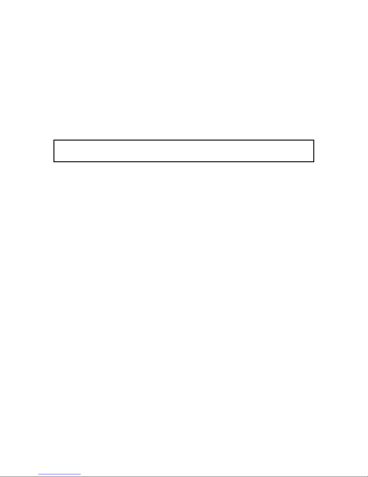
Die Rumpfverstärkung (3) in die rechte Rumpfseite (1) einkleben, dann gemeinsam
die Bowdenzugaußenrohre (4/5), darauf achten, dass diese vorne 10 mm
überstehen. Teil (6) nicht einkleben, wenn Sie die Segelversion mit Schleppkupplung
wünschen.
Die überflüssigen Hebel der Servosteuerkreuze abtrennen und die Servos per
Servotester oder RC- Anlage neutral einstellen.
Page 7
GRAUPNER GmbH & Co. KG D-73230 KIRCHHEIM/TECK GERMANY
Änderungen vorbehalten! Keine Haftung für Druckfehler! Id.-Nr. 0059520 5/2009
7
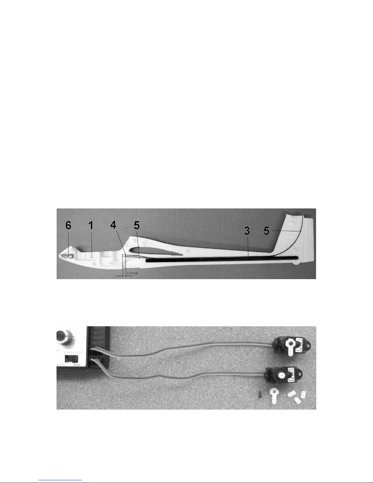
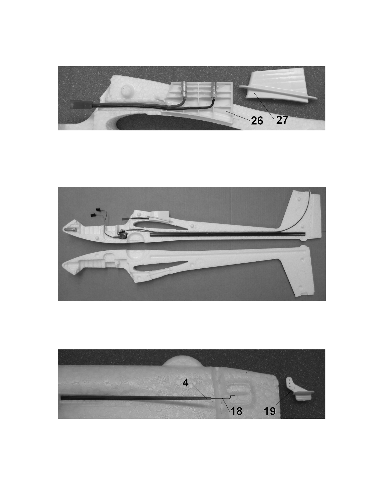
Die Abbildung zeigt die fertig installierten Servos C131. Die Ruderzüge (18) und (20)
in die Servos einhängen und einschieben, dann die beiden Servos in das
Rumpfseitenteil einsetzen, nach vorne drücken und mit je zwei Tropfen
Sekundenklebstoff sichern. Achtung, keinesfalls dünnflüssigen oder zuviel
Sekundenklebstoff verwenden, da dieser sonst in die Servos gelangt und diese
blockiert.
Die Abbildung zeigt die eingeklebte Schleppkupplung bei Version 2. Die
Rumpfnasenverstärkung (6) wird bei dieser Version nicht benötigt.
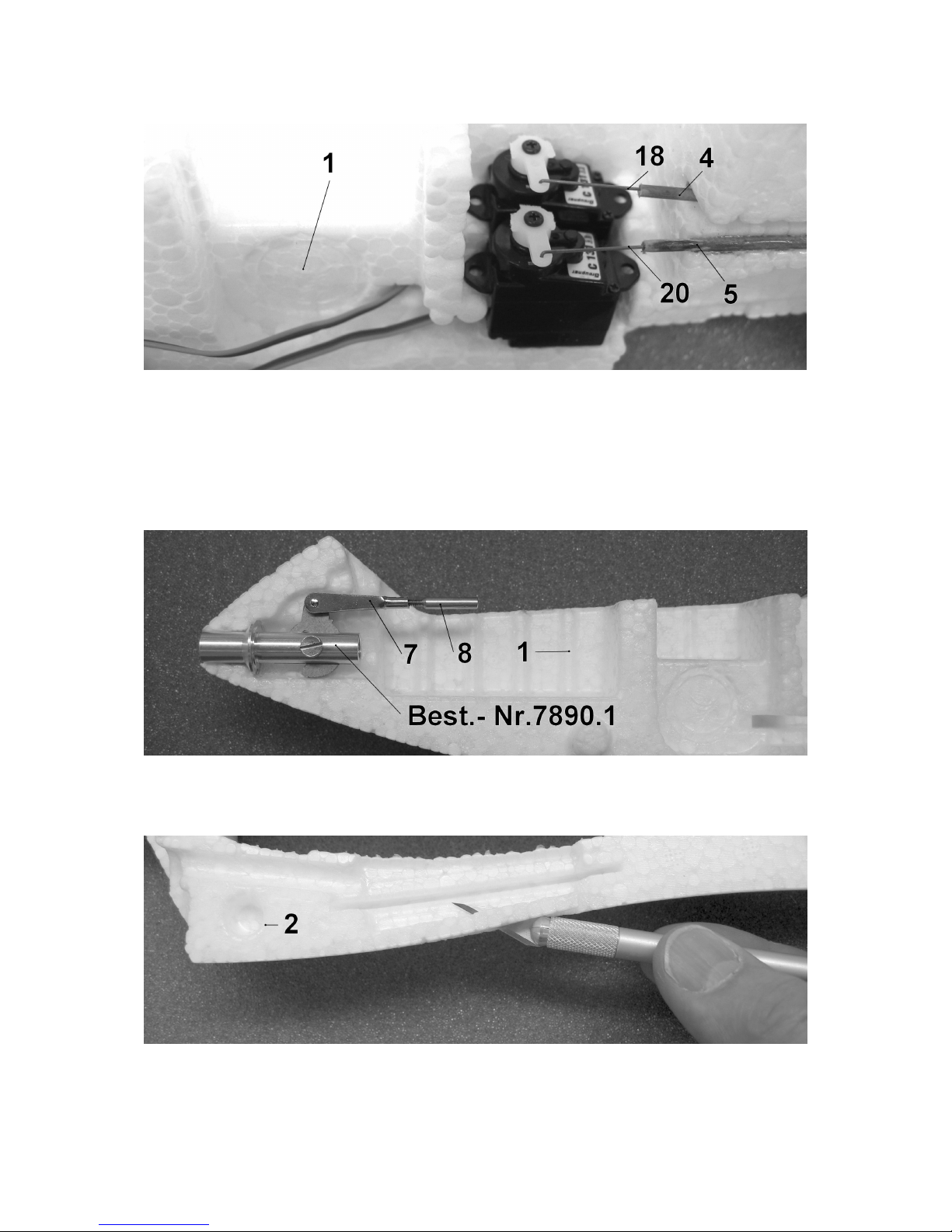
Die Abbildung zeigt das Öffnen der Rumpfoberseite für die Trägerbasishälften (26)
Page 8
GRAUPNER GmbH & Co. KG D-73230 KIRCHHEIM/TECK GERMANY
Änderungen vorbehalten! Keine Haftung für Druckfehler! Id.-Nr. 0059520 5/2009
8
und (27). Diesen und den folgenden Arbeitsvorgang nur bei Elektroversion 3
ausführen.
Achtung, zuerst das BEC-Zuleitungskabel (enthalten bei Best.-Nr. 9401.22)
kürzen und in die noch nicht eingeklebten Goldbuchsen (enthalten bei Best.-Nr.
9401.22) einlöten. Die Goldbuchsen in Teil (26) einkleben, darauf achten, dass kein
Klebstoff in die Buchsen gelangt. Dann die Trägerbasisteile in den vorbereiteten
Rumpf einkleben. Das BEC-Kabel ebenfalls mit Klebstoff sichern.
Die Abbildung zeigt die zum Verkleben vorbereiteten Rumpfseitenteile. Achtung,
dieser Arbeitsvorgang erfordert eine hohe Konzentration. Unbedingt darauf
achten, dass kein Klebstoff in die Ruderzüge gelangt. Zellstoffpapier bereitlegen
um nötigenfalls überschüssigen Klebstoff abzuwischen.
Das Seitenruder durch mehrfaches Biegen leichtgängig machen. Das Ruderhorn
probeweise einsetzen, den Ruderzug (18) exakt passend abwinkeln und abtrennen.
Page 9
GRAUPNER GmbH & Co. KG D-73230 KIRCHHEIM/TECK GERMANY
Änderungen vorbehalten! Keine Haftung für Druckfehler! Id.-Nr. 0059520 5/2009
9
Das Ruderhorn einhängen und einkleben. Tipp: Sofern Sie noch wenig
Flugerfahrung besitzen, außen einhängen, wie abgebildet. Wird ein möglichst großer
Ruderausschlag gewünscht, in der mittleren Bohrung einhängen.
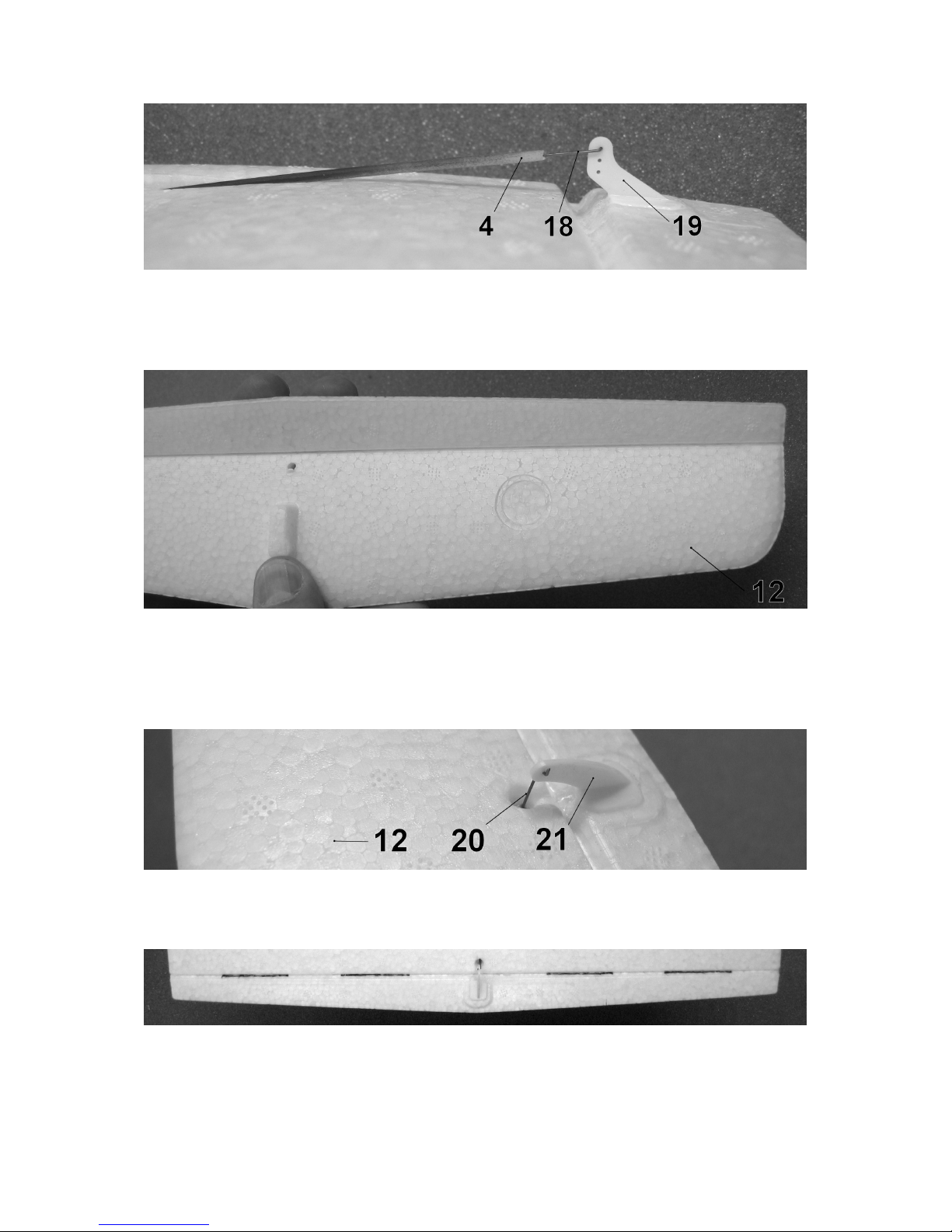
Das Höhenruder vom Höhenleitwerk (12) so lange bis zum Anschlag auf und ab
biegen, bis das Ruder sich leichtgängig bewegen lässt. Das Höhenleitwerk exakt
ausgerichtet auf den Rumpf kleben. Durch Anvisieren von vorne und oben
überprüfen.
Das Anschließen und Einkleben des Höhenruderhornes (21) nach dem gleichen
Prinzip wie bei dem Seitenruderhorn durchführen.
Tipp: Sofern das Höhenruderscharnier zu schwergängig ist, dieses an den auf der
Abbildung schwarz markierten Bereichen durchtrennen.
Page 10
GRAUPNER GmbH & Co. KG D-73230 KIRCHHEIM/TECK GERMANY
Änderungen vorbehalten! Keine Haftung für Druckfehler! Id.-Nr. 0059520 5/2009
10
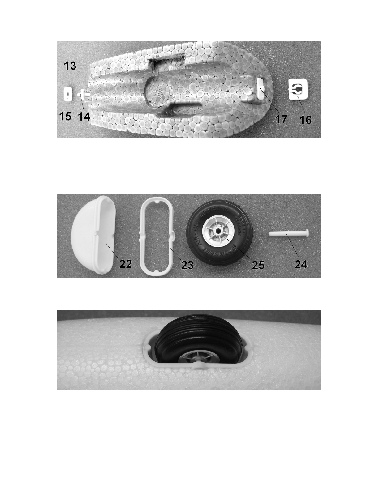
Die Abbildung zeigt die Kabinenhaube (13) mit den Befestigungselementen (14) bis
(17). Die Teile (14) und (17) an die Kabinenhaube kleben, die Teile (15) und (16) in
den Rumpf einkleben. Siehe Baustadienfoto „RC- Installation“. Nötigenfalls, wie auf
dem Foto erkennbar, eine Aussparung für die Servostecker mit dem Balsamesser
heraustrennen.
Die Abbildung zeigt die Einzelteile des Radkastens. Beim Verkleben darauf achten,
dass kein Klebstoff in das Radlager gelangt.
Der fertig in den Rumpf eingeklebte Radkasten.
Die Tragfläche
Page 11

GRAUPNER GmbH & Co. KG D-73230 KIRCHHEIM/TECK GERMANY
Änderungen vorbehalten! Keine Haftung für Druckfehler! Id.-Nr. 0059520 5/2009
11
Den Holm (29) einkleben, die Nut mit Klebeband überkleben.
Die fertige Tragfläche seitlich in den Rumpf einschieben.
Die RC-Installation
Die Abbildung zeigt die Installation der LiPo-Batterie und des Empfängers der
Elektroversion 3. Der PICO 8 Drehzahlregler ist unter dem Empfänger angeordnet.
Mit dem Schließen der BEC-Steckerverbindung, wie auf dem Foto zu sehen, wird die
RC-Anlage eingeschaltet. Wird bei der Elektroversion der Motoraufsatz abgezogen
dient die LiPo-Batterie als Empfängerbatterie. Das BEC-System des PICO 8
Drehzahlreglers bietet die Stromversorgung für maximal 3 Servos und ist für 2 oder
3LiPo-Zellen geeignet.
Hinweise für eine Antriebsversion mit 3 LiPo- Zellen
Das Flugmodell ist in erster Linie für den Antrieb mit 2LiPo-Zellen konzipiert, sofern
Sie 3 LiPo-Zellen z. B. Best.-Nr.7621.3BEC einsetzen wollen, den nachfolgenden
Hinweis beachten. Ein Betrieb mit 3 LiPo-Zellen ist nur im Intervallbetrieb zulässig,
da sonst der SPEED 300-Motor im Motoraufsatz Best.-Nr. 9401.22 auch bei
optimaler Kühlung überlastet wird.
Page 12

GRAUPNER GmbH & Co. KG D-73230 KIRCHHEIM/TECK GERMANY
Änderungen vorbehalten! Keine Haftung für Druckfehler! Id.-Nr. 0059520 5/2009
12
Die Abbildung zeigt die RC-Installation der Segelversion 2 mit zusätzlich
eingebautem Servo für die Schleppkupplung. Die Teile (8) bis (10) mit
Sekundenklebstoff untereinander verkleben. Das Einschalten der Empfangsanlage
erfolgt durch das Einstecken der Empfängerbatterie in Buchse B/T des Empfängers.
Dekor
Eine Lackierung der SOLIDPOR®-Teile ist nicht erforderlich. Sofern Sie eine
Lackierung wünschen, ist dies mit GRAUPNER LEXACOLOR-Sprühlack Best.-Nr.
945...möglich. Die Teile zuvor mit Spannfix-Verdünnung Best.-Nr.1409 lediglich
abwischen, nicht überschleifen.
Mit dem Ausschneiden und Aufkleben der Dekorelemente (30) ist der Bau des
Modells abgeschlossen.
Auswiegen
Das Auswiegen erfolgt in flugfertigem Zustand, also mit kompletter RC-Ausstattung.
Page 13

GRAUPNER GmbH & Co. KG D-73230 KIRCHHEIM/TECK GERMANY
Änderungen vorbehalten! Keine Haftung für Druckfehler! Id.-Nr. 0059520 5/2009
13
Der Schwerpunktbereich liegt zwischen 62 und 72 mm von Tragflächenvorderkante
aus gemessen. Zur Einstellung nötigenfalls Trimmgewichte ( von Best.-Nr. 536 ) in
die Rumpfnase einkleben. Die Schwerpunktlage wird geprüft, indem das Modell im
Schwerpunktbereich unterhalb der Tragfläche mit zwei Fingern unterstützt wird. Das
Modell soll dann waagrecht auspendeln.
Fliegen
Das fertig gebaute Modell mit neutral eingestellten Rudern bei Windstille oder
schwachem Wind einfliegen. Eine leicht gegen die Windrichtung abfallende Wiese ist
als Gelände optimal geeignet.
Das Modell per Handstart gegen die Windrichtung in die Luft schieben. Die
richtige Startgeschwindigkeit wird durch einige Laufschritte erreicht. Das
Modell durch minimale Seiten- und Höhenruderkorrekturen steuern. Die
Feintrimmung erfolgt über die Trimmschieber unterhalb, bzw. neben den
Steuerknüppeln. Die Landung exakt gegen die Windrichtung mit abgeschaltetem
Motor durchführen. Vor dem Aufsetzen die Fluggeschwindigkeit des Modells durch
dosierte Höhenruderausschläge reduzieren. Die Landung immer gegen die
Windrichtung ausführen.
GRAUPNER Modellbau wünscht viele schöne Flüge mit dem neuen Flugmodell
DISCUS 2CT
Der komplette Bausatzinhalt zur Übersicht
Page 14

GRAUPNER GmbH & Co. KG D-73230 KIRCHHEIM/TECK GERMANY
Änderungen vorbehalten! Keine Haftung für Druckfehler! Id.-Nr. 0059520 5/2009
14
Stückliste DISCUS 2CT
Nr. Bezeichnung Stück Werkstoff Abmessung in mm
1 Rumpfseite rechts 1
SOLIDPOR®
Fertigteil
2 Rumpfseite links 1
SOLIDPOR®
Fertigteil
3 Rumpfverstärkung 1 CFK Ø 10/9x450
4 Bowdenzugaußenrohr Seitenruder 1 Polyamid Ø 1,9x530
5 Bowdenzugaußenrohr Höhenruder 1 Polyamid Ø 1,9x615
6 Rumpfnasenverstärkung 1 Stahl M8x25
7 Gabelkopf 1 Stahl M2 Fertigteil
8 Gewindebuchse 1 Stahl M2 Fertigteil
9 Gestängeaußenrohr 1 Polyamid Ø 1,9x10⁵
10 Gestängeverstärkung 1 Stahl Ø 0,5x110
11 nicht belegt
12 Höhenleitwerk 1
SOLIDPOR®
Fertigteil
13 Kabinenhaube 1
SOLIDPOR®
Fertigteil
14 Haltestift 1 ABS Fertigteil
15 Stiftaufnahme 1 ABS Fertigteil
16 Halteclip 1 ABS Fertigteil
17 Zapfen 1 ABS Fertigteil
18 Seitenruderzug 1 Stahl Ø 0,5x560
19 Seitenruderhorn 1 ABS Fertigteil
20 Höhenruderzug 1 Stahl Ø 0,5x645
21 Höhenruderhorn 1 ABS Fertigteil
22 Radkasten 1 ABS Fertigteil
23 Radaufnahme 1 ABS Fertigteil
24 Radachse 1 ABS Fertigteil
25 Rad 1 Kunststoff Ø 40x15
26 Trägerbasishälfte rechts 1 ABS Fertigteil
27 Trägerbasishälfte links 1 ABS Fertigteil
28 Tragfläche 1
SOLIDPOR®
Fertigteil
29 Holm 1 CFK Ø 4/3x700
30 Dekorelement 12 Klebefolie Zuschnitt
Weiterhin enthalten 2 Stück Ersatz-Ruderhörner aus ABS
Technische Daten DISCUS 2CT
Spannweite ca. 1200 mm
Länge ü.a. ca. 750 mm
Tragflächenprofil HQ 3,0/12
Höhenleitwerksprofil NACA 009
Tragflächenin halt ca. 13,5 dm²
Höhenleitwerksinhalt ca. 2,5 dm²
Gesamtflächeninhalt ca. 16,0 dm²
Gesamtflächenbelastung ca. 22 g/dm²
Fluggewicht ca. 330 bis 410g
.
Page 15

GRAUPNER GmbH & Co. KG D-73230 KIRCHHEIM/TECK GERMANY
Änderungen vorbehalten! Keine Haftung für Druckfehler! Id.-Nr. 0059520 5/2009
15
BUILDING INSTRUCTIONS
Please be sure to read and observe the following safety notes.
If you ever dispose of the model, it is important to pass on the complete building
instructions, including Safety Notes, to the new owner.
Safety Notes
You must have valid third-party insurance which covers the hazards involved in model
flying; this is now a legal requirement.
Before you start assembling the aircraft, please read right through these instructions
attentively. You alone are responsible for the safe operation of your radio-controlled
model. Young persons should only be permitted to build and fly this model under the
instruction and supervision of an adult who is aware of the requirements and potential
hazards involved in this activity.
In legal terms our models are classed as aircraft, and as such are subject to legal
regulations and restrictions which must be observed at all times. Our brochure
“Modellflugrecht, Paragrafen und mehr” (Model Aviation Law, Legal Requirements and
more) is available under Order No. 8034.02, and contains a summary of all these rules.
Your local model shop should have a copy which you can read. There are also Post
Office regulations concerning your radio control system, and these must be observed.
Refer to your RC system instructions for more details.
Be sure to use only those parts included in the kit, together with other genuine
Graupner accessories and replacement parts as recommended expressly by us. Even
if you change a single component you can no longer be sure that the system will work
reliably, and such changes also invalidate your guarantee.
Avoid short-circuits and reversed polarity in all electrical circuits.
The high energy density of rechargeable batteries involves a risk of fire and even
explosion.
A radio-controlled model aircraft can only work properly and fulfil your expectations if
it is built very carefully and in accordance with the building instructions. If you wish to
avoid injuring people and damaging property it is essential to be careful and
painstaking at all stages of building and operating your model. Nobody would climb
into a full-size sailplane and try to fly it without undergoing training beforehand, and
model flying is a skill which needs to be learned in just the same way.
As manufacturers we are not in a position to influence the way you build and operate
your RC model aircraft, and for this reason we deny all liability. All we can do is
expressly point out the hazards involved in this activity.
We suggest that you ask an experienced model flyer for help, or join a model club or
flight training school. Your local model shop and the specialist magazines are
excellent sources of information. If at all possible, it is always best to join a club and
fly at the approved model flying site.
Adhesives and paints contain solvents which may be hazardous to health under
certain circumstances. Read and observe the notes and warnings supplied by the
manufacturer of these materials.
Page 16

GRAUPNER GmbH & Co. KG D-73230 KIRCHHEIM/TECK GERMANY
Änderungen vorbehalten! Keine Haftung für Druckfehler! Id.-Nr. 0059520 5/2009
16
The operator of the model must be in full possession of his or her bodily and mental
faculties. As with car driving, operating a model aircraft under the influence of alcohol
or drugs is not permissible under any circumstances.
If there are passers-by or spectators at your flying site, make sure that they are aware
of the dangers inherent in your activity before you start the motor, and insist that they
keep a safe distance away.
Always keep a safe distance away from people and objects when flying; never fly low
over people’s heads, and never fly directly towards them.
Radio-controlled models should only be flown in “normal” weather conditions, i.e. a
temperature range of -5° to +35° C. More extreme temperatures can lead to changes in
battery capacity and material characteristics, weakened glued joints and other
unwanted effects.
All model flyers should behave in a way that minimises the danger to people and
property. Never act in any manner which will disturb other flyers and jeopardise safe,
orderly flying at the site.
Never operate your model aircraft close to high-tension overhead cables, industrial
sites, residential areas, public roads, school playgrounds, sports grounds etc.
Pre-flight checks
Before every flying session check that all the model’s working systems are
functioning correctly. Switch the transmitter on and extend the aerial to full length,
then switch on the receiver. Ensure that all the control surfaces are at centre (trims
neutral), that they deflect to both sides and in the correct “sense” (left stick = left
rudder, etc.). Ask a friend to hold the model for you, and repeat the checks with the
motor running.
If you are flying a model aircraft for the first time we strongly recommend that you ask
an experienced modeller to check the aeroplane first and be ready to help you during
the first few flights.
Don’t ignore our warnings. They refer to materials and situations which, if ignored,
can result in fatal injury or permanent damage.
Propellers and other rotating parts which are powered by a motor constitute a
permanent hazard and represent a real risk of injury. Don’t touch them with any part of
your body. For example, a propeller spinning at high speed can easily cut your finger
badly.
Keep well clear of the rotational plane of the propeller. You never know when some
part may come loose and fly off at high speed, hitting you or anybody else in the
vicinity. Under certain circumstances this can result in serious personal injury. Never
touch the revolving propeller with any object.
Ensure that it is impossible for any object to stall or block the propeller.
Every time you intend to operate your model check carefully that it and everything
attached to it (e.g. propeller, RC components etc.) is in good condition and
undamaged. If you find a fault, do not fly the model until you have corrected it.
Page 17

GRAUPNER GmbH & Co. KG D-73230 KIRCHHEIM/TECK GERMANY
Änderungen vorbehalten! Keine Haftung für Druckfehler! Id.-Nr. 0059520 5/2009
17
Satisfy yourself that your frequency is vacant before you switch on. Radio interference
caused by unknown sources can occur at any time without warning. If this should
happen, your model will be uncontrollable and completely unpredictable. Never leave
your radio control system unguarded, as another person might pick it up and try to
use it.
Do not switch on the electric motor unless you are sure that there is nothing in the
rotational plane of the propeller. Never attempt to stop the spinning propeller. Electric
motors with the propeller attached should only be run when firmly mounted.
If you are to fly your model safely and avoid problems, it is essential that you are
aware of its position and attitude throughout each flight - so don’t let it fly too far
away! If you detect a control problem or interference during a flight, immediately land
the model to prevent a potential accident. Models must always give way to full-size
aircraft. Take-off and landing strips should be kept free of people and other obstacles.
Your RC system can only work reliably if the batteries are kept fully charged.
Never use batteries which are hot, faulty or damaged. At all times heed the
instructions provided by the battery manufacturer.
Before each flight check that all functions on the model aircraft are working correctly,
and that the radio control system is in good order and operating at full range.
Note that the motor control (throttle) function on the transmitter must always be
moved to the OFF position as the first stage in preparing for a flight. To avoid the
danger of the electric motor bursting into life unexpectedly, always switch on the
transmitter first, and only then the receiving system. The opposite applies at the end
of a flight: always switch off the receiving system first, and finally the transmitter.
Check that the control surfaces follow the movement of the transmitter sticks.
After use, remove the flight battery from the model, and store it in the discharged state
at a temperature of around +5° to +25°C. Keep it in a safe place, well out of the reach
of children.
Please don’t misunderstand the purpose of these notes. We only want to make you
aware of the many dangers and hazards which can arise if you work carelessly or
irresponsibly. If you take reasonable care, model flying is a highly creative,
instructive, enjoyable and relaxing pastime.
Manufacturer’s declaration
If material defects or manufacturing faults should arise in a product distributed by us
in the Federal Republic of Germany and purchased by a consumer (§ 13 BGB), we,
Graupner GmbH & Co. KG, D-73230 Kirchheim/Teck, Germany, acknowledge the
obligation to correct those defects within the limitations described below.
The consumer is not entitled to exploit this manufacturer’s declaration if the failure in
the usability of the product is due to natural wear, use under competition conditions,
incompetent or improper use (including incorrect installation) or external influences.
This manufacturer’s declaration does not affect the consumer’s legal or contractual
rights regarding defects arising from the purchase contract between the consumer
and the vendor (dealer).
Extent of the guarantee
Page 18

GRAUPNER GmbH & Co. KG D-73230 KIRCHHEIM/TECK GERMANY
Änderungen vorbehalten! Keine Haftung für Druckfehler! Id.-Nr. 0059520 5/2009
18
If a claim is made under guarantee, we undertake at our discretion to repair or replace
the defective goods. We will not consider supplementary claims, especially for
reimbursement of costs relating to the defect (e.g. installation / removal costs) and
compensation for consequent damages unless they are allowed by statute. This does
not affect claims based on legal regulations, especially according to product liability
law.
Guarantee requirements
The purchaser is required to make the guarantee claim in writing, and must enclose
original proof of purchase (e.g. invoice, receipt, delivery note) and this guarantee card.
He must send the defective goods to us at his own cost, using the address stated
above.
The purchaser should state the material defect or manufacturing fault, or the
symptoms of the fault, in as accurate a manner as possible, so that we can check if
our guarantee obligation is applicable.
The goods are transported from the consumer to us and from us to the consumer at
the risk of the consumer.
Duration of validity
This declaration only applies to claims made to us during the claim period as stated in
this declaration. The claim period is 24 months from the date of purchase of the
product by the consumer from a dealer in the Federal Republic of Germany (date of
purchase). If a defect arises after the end of the claim period, or if the evidence or
documents required according to this declaration in order to make the claim valid are
not presented until after this period, then the consumer forfeits any rights or claims
from this declaration.
Limitation by lapse of time
If we do not acknowledge the validity of a claim based on this declaration within the
claim period, all claims based on this declaration are barred by the statute of
limitations after six months from the time of implementation; however, this cannot
occur before the end of the claim period.
Applicable law
This declaration, and the claims, rights and obligations arising from it, are based
exclusively on the pertinent German Law, without the norms of international private
law, and excluding UN retail law.
Introduction
The DISCUS 2CT is a semi-scale RC model aeroplane with an excellent performance in the
air. Please note that the model can be built in any of three versions, and different
accessories are required for each variant. It is up to you to decide on one version before you
start construction, as it will be impossible to change your mind later. For safety reasons the
aircraft’s all-up weight must not exceed 500 g.
1. Glider version
2. Glider version (aero-tow)
3. Electric version *
* This version is particularly recommended, as the motor pylon can be removed in
seconds, and the model can then be flown as a pure glider.
Page 19

GRAUPNER GmbH & Co. KG D-73230 KIRCHHEIM/TECK GERMANY
Änderungen vorbehalten! Keine Haftung für Druckfehler! Id.-Nr. 0059520 5/2009
19
RC accessories (not included)
This model should be flown with an FM radio control system such as the mx-12 to mc-24, or
an iFS radio control system. For more information about RC systems and components
please refer to the main GRAUPNER FS catalogue.
mx-12 FM 35* FM radio control set Order No. 4722
* In many countries the 35 MHz frequency band is reserved exclusively for model aircraft.
Transmitter charge lead Order No. 3022
Receiver charge lead (glider versions only) Order No. 3021
Charge lead with BEC connector (electric version only) Order No. 3037
ULTRAMAT 8 battery charger Order No. 6411
C 131 servo (two required) Order No. 7121
Nose ballast Order No. 536
Accessories for glider versions (not included)
Aero-tow mechanism Receiver battery Tow-release servo
Order No. Order No. Order No.
6 mm I.D. GRAUPNER C 131
7890.1 4N-600 AA 4.8 V / 0.6 Ah 2585 7121
Accessories for electric version (not included)
Motor pylon Flight battery Speed controller
Order No. Order No. Order No.
SPEED 300 7.2 V GRAUPNER PICO 8 BEC
9401.22 2 LiPo 800 7.4 V / 0.8 Ah 7621.2BEC 7171
Essential tools and adhesives (not included)
Balsa knife Order No. 980
Cyano-acrylate glue Order No. 5821
Cyano activator Order No. 953.150
220 V soldering iron (electric version only) Order No. 826
Electronic-grade cored solder (electric version only) Order No. 1176.1
The following items are also required: side-cutters, flat-nose pliers, paper scissors,
screwdriver, adhesive tape.
Building instructions
Please read right through these building instructions before you start construction, so that
you gain a general understanding of the sequence of events. Before you commence work on
a particular stage, lay out the parts required together with the tools and adhesives. You will
need a smooth, completely flat surface for assembling the model; a layer of foam on the
building board will help to prevent damage to the foam surfaces. As adhesive for all joints
use cyano-acrylate glue (“cyano”) with activator unless stated otherwise. Joints are best
made by applying cyano to one surface, and spraying the mating surface with activator.
Please take particular care to avoid cyano getting onto your hands and the surfaces of the
model; wipe off excess glue immediately using paper towel.
Caution: cyano-acrylate adhesives must not be allowed to come into contact with any
part of your body, and in particular not with the eyes. We therefore recommend that
you wear rubber gloves and protective goggles. Make sure your workshop is well
ventilated. Keep the adhesive in a safe place, well out of the reach of children. On no
account use Styrofoam cyano-acrylate (“foam cyano”), white glue (PVA wood glue) or
Page 20

GRAUPNER GmbH & Co. KG D-73230 KIRCHHEIM/TECK GERMANY
Änderungen vorbehalten! Keine Haftung für Druckfehler! Id.-Nr. 0059520 5/2009
20
epoxy resin adhesives, as these glues do not produce durable joints between any of
the kit materials and the SOLIDPOR® high-density foam.
Fuselage, tail surfaces and canopy
Glue the fuselage reinforcement (3) in the right-hand fuselage side (1), then fit both the
snake outer sleeves (4 and 5); note that they should project by 10 mm at the front end. If you
wish to build the glider version with aero-tow release, do not glue the nose reinforcement (6)
in place.
Remove the unwanted arms from the cruciform servo output devices, and set them to centre
(neutral) using a servo tester or the RC system.
The photo shows the two C131 servos installed in the fuselage. This is the procedure: first
connect the pre-formed end of the steel pushrods (18) and (20) to the servo output arms,
then slip the pushrods into the snake outers before fitting the two servos in the fuselage
shell. Push the servos forward, and secure each with two drops of cyano. Caution: on no
account use thin (low-viscosity) cyano, or an excessive quantity of glue, as the
adhesive could then run into the servos and jam up the mechanism.
Order No. 7890.1
The photo shows the aero-tow mechanism (required for Version 2) installed in the fuselage
side. The fuselage nose reinforcement (6) is not required for this version.
The illustration shows the method of opening up the top of the fuselage to accommodate the
pylon base shells (26) and (27). This, and the following procedure, are only required for
the electric model, Version 3.
Note: it is important to shorten the BEC lead (included in Order No. 9401.22) as shown,
and solder the wires to the gold-contact sockets (included in Order No. 9401.22) before
installing these parts. Glue the gold-contact sockets in part (26), taking care not to allow
any glue to run inside the sockets. The pylon base shells can now be glued in the prepared
fuselage. Glue the BEC lead in its channel.
The picture shows both fuselage shells prior to joining. Caution: the next step calls for
considerable concentration. Take great care not to allow adhesive to run onto the
pushrods or into the snake sleeves. Glue the fuselage shells together. Keep some paper
towel handy, and wipe off excess adhesive immediately.
Flex the rudder to and fro repeatedly to free up the integral foam hinge. Place the rudder
horn in its recess, and mark the point on the rudder pushrod (18) where it crosses the linkage
hole. Bend the pushrod end to the shape shown.
Connect the rudder horn to the pushrod, and glue the horn in the recess in the rudder. Tip: if
you are relative beginner to model flying, use the outer linkage hole as shown. If you want a
more lively rudder response, use the middle hole of the three.
Flex the elevator - attached to the tailplane (12) - to and fro repeatedly, moving it to the limits
of travel, until the integral hinge operates freely. The tailplane can now be glued to the top of
the fin: check that it is exactly central and at right-angles to the fin by sighting over it from the
nose and from above.
Page 21

GRAUPNER GmbH & Co. KG D-73230 KIRCHHEIM/TECK GERMANY
Änderungen vorbehalten! Keine Haftung für Druckfehler! Id.-Nr. 0059520 5/2009
21
The elevator horn (21) is connected to the pushrod and glued to the elevator using the same
method as described for the rudder horn.
Tip: if the elevator is still excessively stiff, cut away the areas of the hinge marked black in
the photo.
The photo shows the canopy (13) with the fixings (14) to (17). Glue parts (14) and (17) to the
ends of the canopy; parts (15) and (16) are installed in the fuselage - these parts are shown
in the stage photo “RC installation”. You may need to cut a notch in the canopy using a balsa
knife to clear the servo connector; this is shown in the photograph.
The illustration shows the wheel box components. Glue the parts together, taking care to
avoid glue running into the wheel bearings.
The wheel box assembly glued in the underside of the fuselage.
The wing
Glue the spar (29) in the wing, and apply a length of adhesive tape over the channel.
Slide the finished wing into the fuselage from one side and set it exactly central.
The RC installation
The first photo shows the installation of the LiPo battery and the receiver in Version 3 - the
electric model. The PICO 8 speed controller is located below the receiver. The RC system is
switched on by connecting the BEC plug and socket, as shown in the picture. If you remove
the motor pylon, the LiPo battery is used as the receiver battery. The BEC system of the
PICO 8 speed controller can supply current to up to three servos, and is designed for two ore
three LiPo cells.
Notes on the use of three LiPo cells for the powered version
This model aircraft is primarily intended for a two-cell LiPo pack, but if you wish to use a
three-cell battery, such as Order No. 7621.3BEC, please note the following point:. Please
remember that the motor should only be run for brief periods with a three-cell LiPo pack,
otherwise the SPEED 300 motor in the motor pylon, Order No. 9401.22, will be overloaded
even if effective cooling measures are taken.
This picture shows the RC installation in Version 2 - the glider - with an additional servo
installed for the aero-tow release. Glue parts (8), (9) and (10) together using cyano. In this
version the receiving system is switched on by plugging the receiver battery into the receiver
socket marked B/T.
Decals
It is not necessary to paint the SOLIDPOR® foam components. If you wish to apply a colour
finish, this is possible using GRAUPNER LEXACOLOR spray paints, Order No. 945… Wipe
the foam surfaces with cellulose thinners, Order No. 1409, beforehand to improve paint
adhesion; don’t sand the surfaces.
Cut out and apply the self-adhesive decals (30) to complete the model.
Balancing
The model should be balanced in its fully-assembled state, ready to fly, i.e. with the complete
RC system installed.
Page 22

GRAUPNER GmbH & Co. KG D-73230 KIRCHHEIM/TECK GERMANY
Änderungen vorbehalten! Keine Haftung für Druckfehler! Id.-Nr. 0059520 5/2009
22
The Centre of Gravity range is between 62 and 72 mm, measured from the wing root leading
edge. Add ballast weight (Order No. 536) to the extreme nose to achieve this. Check the CG
by supporting the model under both wing roots on two fingertips; when correctly balanced, it
should hang level when your fingers are at the stated position.
Flying
We recommend that you test-fly the model on a day with little or no breeze. A large, grassy
field, sloping gently into wind, forms the ideal flying site. Check that both the control surfaces
are at centre.
Push the model forward, directly into any wind, with the wings and fuselage level.
Trotting forward for a few paces gives the correct launch speed. Keep the model flying
straight ahead with minimal rudder and elevator corrections as necessary. If the model does
not fly straight and level by itself, use the trim sliders located below and next to the
transmitter sticks to correct unwanted tendencies. Always land the machine on the glide
(motor stopped), heading exactly into wind. Reduce the model’s airspeed just before touchdown by progressively applying up-elevator to flare out. Always land straight into any wind.
All of us at GRAUPNER Modellbau hope you have many fine flights with your new DISCUS
2CT.
An overall view of the complete kit contents.
Parts List - DISCUS 2CT
No. Description No. off Material Dimensions in mm
1 R.H. fuselage shell 1 SOLIDPOR® Ready made
2 L.H. fuselage shell 1 SOLIDPOR® Ready made
3 Fuselage reinforcement 1 CFRP 10 / 9 Ø x 450
4 Rudder snake outer sleeve 1 Nylon 1.9 Ø x 530
5 Elevator snake outer sleeve 1 Nylon 1.9 Ø x 615
6 Fuselage nose reinforcement 1 Steel M8 x 25
7 Clevis 1 Steel M2, ready made
8 Threaded coupler 1 Steel M2, ready made
9 Pushrod outer sleeve 1 Nylon 1.9 Ø x 105
10 Metal pushrod 1 Steel 0.5 Ø x 110
11 No part
12 Tailplane 1 SOLIDPOR® Ready made
13 Canopy 1 SOLIDPOR® Ready made
14 Canopy retaining pin 1 ABS Ready made
15 Canopy pin socket 1 ABS Ready made
16 Retaining clip 1 ABS Ready made
17 Spigot 1 ABS Ready made
18 Rudder pushrod 1 Steel 0.5 Ø x 560
19 Rudder horn 1 ABS Ready made
20 Elevator pushrod 1 Steel 0.5 Ø x 645
21 Elevator horn 1 ABS Ready made
22 Wheel box 1 ABS Ready made
23 Wheel axle support 1 ABS Ready made
24 Wheel axle 1 ABS Ready made
25 Landing wheel 1 Plastic 40 Ø x 15
26 R.H. motor pylon base shell 1 ABS Ready made
Page 23

GRAUPNER GmbH & Co. KG D-73230 KIRCHHEIM/TECK GERMANY
Änderungen vorbehalten! Keine Haftung für Druckfehler! Id.-Nr. 0059520 5/2009
23
27 L.H. motor pylon base shell 1 ABS Ready made
28 Wing 1 SOLIDPOR® Ready made
29 Wing spar 1 CFRP 4 / 3 Ø x 700
30 Decal 12 Self-adhesive film Sheet
The kit also includes two spare ABS control surface horns.
Specification DISCUS 2CT
Wingspan approx. 1200 mm
Overall length approx. 750 mm
Wing section HQ 3.0/12
Tailplane section NACA 009
Wing area approx. 13.5 dm²
Tailplane area approx. 2.5 dm²
Total surface area approx. 16.0 dm²
Total surface area loading approx. 22 g / dm²
All-up weight approx. 330 to 410g
Page 24

GRAUPNER GmbH & Co. KG D-73230 KIRCHHEIM/TECK GERMANY
Änderungen vorbehalten! Keine Haftung für Druckfehler! Id.-Nr. 0059520 5/2009
24
INSTRUCTIONS DE MONTAGE
Veuillez absolument observer les conseils de sécurité qui vont suivre.
Si le modèle doit être cédé à une autre personne, ces conseils de sécurité ainsi que les
instructions de montage complètes devront impérativement lui être remis.
Conseils de sécurité
Une assurance est obligatoire pour l’utilisation de votre modèle, comme il est prescrit par la
loi
.
Avant de tenter la première mise en service, les instructions de montage et d’utilisation
devront être attentivement lus. Vous être seul responsable de la sécurité d’utilisation de votre
modèle R/C. Les jeunes modélistes devront effectuer les assemblages et utiliser le modèle
sous la surveillance d’un adulte familiarisé avec les particularités et les dangers possibles que
peut présenter un modèle R/C.
Les modèles d'avions R/C sont des appareils pouvant être dangereux et qui exigent de leur
utilisateur une grande compétence et la conscience de sa responsabilité.
Il conviendra d'utiliser exclusivement les éléments fournis dans le kit de montage ainsi que les
accessoires d'origine Graupner et les pièces détachées conseillées. Si un seul composant de
la propulsion est remplacé, une parfaite sécurité de fonctionnement de peut plus être assurée
et peut entraîner la perte du bénéfice de la garantie.
Evitez les courts circuits et les inversions de polarité.
Par la forte énergie emmagasinée par les batteries LiPo, il existe un danger d’explosion et
d’incendie.
Un modèle volant R/C ne peut évoluer correctement que s'il a été construit et réglé
conformément aux instructions de montage et seule une utilisation prudente et responsable
évitera de provoquer des dommages matériels ou corporels. Le pilotage sûr d’un modèle réduit
n’est possible qu’après un entraînement ou un écolage appropriés.
Le fabricant n'a cependant aucune possibilité d'influencer la construction et l'utilisation d'un
modèle de sa production. C'est pourquoi nous attirons ici l'attention sur les dangers
représentés en dégageant toute responsabilité.
Faites-vous assister par un modéliste expérimenté, ou inscrivez-vous dans une association ou
dans une école de pilotage. Consultez en outre votre revendeur et la Presse spécialisée. Le
mieux est de faire partie d'un club d'aéromodélisme pour pouvoir voler sur un terrain autorisé.
Les colles et les peintures contiennent des solvants qui dans certaines conditions peuvent être
nocifs pour la santé. Pour cette raison, observez impérativement le mode d'emploi et les
avertissements indiqués par le fabricant correspondant.
L'utilisateur doit être en pleine possession de ses facultés physiques et mentales. Comme
pour la conduite des automobiles, le pilotage des modèles volants sous l'effet de l'alcool ou de
la drogue n'est pas autorisé.
Avant de faire voler votre modèle, informez tous les passants et les spectateurs sur les
dangers qu'il peut présenter et demandez-leur de se tenir à une distance de sécurité d’au
moins 5 m derrière le champ de rotation de l’hélice.
Tenez-vous à une distance de sécurité suffisante de personnes ou d'objets; ne survolez jamais
de personnes à basse altitude et ne volez jamais dans leur direction.
Page 25

GRAUPNER GmbH & Co. KG D-73230 KIRCHHEIM/TECK GERMANY
Änderungen vorbehalten! Keine Haftung für Druckfehler! Id.-Nr. 0059520 5/2009
25
Un modèle volant R/C ne doit voler que par des températures extérieures comprises entre – 5°
à + 35°C. Des températures extrêmes peuvent conduire par ex. à une modification de la
capacité des accus, des propriétés des matériaux et de la résistance des collages.
Chaque modéliste doit se comporter de façon à ce que l'ordre et la sécurité publique, vis-à-vis
des autres personnes et des biens, ainsi que l'activité des autres modélistes ne soient pas mis
en danger, ni perturbés.
Ne faites jamais voler votre modèle à proximité des lignes à haute tension, dans les zones
industrielles, les agglomérations, sur les voies publiques, les places, dans les cours d'école,
les parcs et les aires de jeux, etc…
Vérifications avant le départ
Effectuez une vérification des fonctions avant chaque utilisation. Pour cela, mettez l’émetteur
en contact, ensuite la réception et contrôlez si toutes les gouvernes sont au neutre, si elles
fonctionnent impeccablement et si elles débattent dans le bons sens. Répétez cette vérification
avec le moteur en marche en faisant tenir le modèle par un aide.
Pour les premiers essais d’un modèle volant, il est toujours avantageux d’avoir un aide
expérimenté à ses côtés qui effectuera les vérifications et assistera les premiers vols.
Les avertissements donnés devront être impérativement respectés. Leur non observation peut
conduire à de sérieux dommages et dans les cas extrêmes à des blessures graves.
Les hélices et en général toutes les pièces mécaniques entraînées par un moteur présentent
un danger de blessures permanent et ne doivent être touchées par aucune partie du corps!
Une hélice tournant à haut régime peut par ex. couper un doigt!
Ne vous tenez jamais dans le champ de rotation d'une hélice! Une pièce peut se détacher et
être éjectée à haute vitesse avec une forte inertie et vous toucher, ou une tierce personne.
Veillez également à ce qu'aucun objet quelconque vienne en contact avec l'hélice en rotation.
Le blocage de l’hélice par un objet quelconque doit absolument être exclu.
Avant chaque utilisation, vérifiez le modèle et toutes les pièces qui y sont rattachées (par ex.
hélice, réducteur, éléments R/C, etc…) pour détecter une possible détérioration. Ce n'est
qu'après avoir remédié à tous les défauts éventuels que le modèle pourra être mis en vol.
Assurez-vous que la fréquence que vous utilisez est libre avant de mettre votre émetteur en
contact! Une perturbation peut toujours se produire pour une cause inconnue, sans prévenir!
Le modèle devient alors incontrôlable et livré à lui-même! Ne laissez pas votre émetteur sans
surveillance pour éviter une manipulation par un tiers.
Ne mettez le moteur électrique en contact que lorsque rien ne se trouve dans le champ de
rotation de l’hélice. Faites tourner le moteur électrique avec l’hélice montée uniquement
lorsqu’il est solidement fixé dans le modèle
.
La position du modèle doit être nettement identifiable durant tout le vol pour garantir un
pilotage sûr. Si vous remarquez l'influence d'une perturbation durant le vol, préparez-vous
immédiatement à atterrir pour des raisons de sécurité. Durant le départ et le processus
d'atterrissage, le terrain doit être libre de toute personne et d'obstacle.
Veillez toujours au bon état de charge des accus, car autrement le parfait fonctionnement de
l'ensemble R/C ne peut être garanti.
N’utilisez jamais de batteries échauffées, défectueuses ou détériorées. Observez les
prescriptions d’utilisation indiquées par le fabricant des batteries
Avant chaque vol, effectuez une vérification complète du bon fonctionnement de l’installation
R/C ainsi que du modèle et faites un essai de portée.
Pour faire un essai de fonctionnement du moteur, assurez-vous d’abord que l’organe de
commande soit sur la position COUPE sur l’émetteur. Mettez ensuite d’abord l’émetteur en
Page 26

GRAUPNER GmbH & Co. KG D-73230 KIRCHHEIM/TECK GERMANY
Änderungen vorbehalten! Keine Haftung für Druckfehler! Id.-Nr. 0059520 5/2009
26
contact, ensuite la réception pour éviter un démarrage involontaire du moteur. Procédez
inversement pour couper le contact ; d’abord celui de la réception, ensuite celui de l’émetteur.
Vérifiez si les gouvernes se déplacent dans le sens correspondant des manches de
commande.
Retirez toutes les batteries du modèle après son utilisation et conservez les seulement à l’état
déchargé (env. 0,9 V par élément) et hors de la portée des enfants, sous une température
d’env. + 5º C bis + 25º C.
Ces conseils mettent en évidence la diversité des dangers pouvant résulter d'une manipulation
incorrecte et irresponsable. Leur observation permettra de pratiquer en toute sécurité ce loisir
créatif et éducatif que représente l'aéromodélisme.
Déclaration du fabricant
Déclaration du fabricant Graupner GmbH & Co. KG
Contenu de la déclaration du fabricant
Lorsqu’un article que nous distribuons dans la République Fédérale d’Allemagne acquis par
un consommateur (§ 13 BGB) présente un défaut de matière ou de fabrication, nous la Firme
Graupner GmbH & Co. KG, Kirchheim Teck, prenons en charge la suppression du défaut de
l’article dans les conditions ci après.
Le consommateur ne peut pas valider le droit de déclaration du fabricant lorsque le défaut de
l’article provient d’une usure naturelle, d’une utilisation dans des conditions de compétition,
d’une mauvaise utilisation (incluant le montage) ou d’influences extérieures.
Cette déclaration du fabricant laisse inchangés le droit et les réclamations légales ou
contractuelles du consommateur provenant du contrat d’achat vis à vis de son vendeur (le
détaillant).
Etendue de la garantie
En cas de garantie, nous faisons le choix de réparer ou d’échanger la marchandise
défectueuse. Toutes autres réclamations, particulièrement sur le remboursement des coûts
engendrés par le défaut (par ex. coûts de montage/démontage) et la compensation de
dommages provoqués en conséquence – même autorisés légalement – sont exclues. Les
réclamations provenant des réglementations légales, en particulier selon la loi de la
responsabilité du fabricant, ne seront pas ici abordées.
Droit à la garantie
L’acheteur peut faire valoir le droit à la garantie en joignant le bon d’achat original (par
exemple facture, ticket de caisse, bon de livraison) et cette carte de garantie. Il doit en outre
retourner la marchandise défectueuse à ses frais à l’adresse suivante :
GRAUPNER Service France
86 rue St Antoine
F-57601 Forbach-Oeting
L’acheteur doit indiquer concrètement le défaut de matière ou de fabrication ou le symptôme
du défaut pour permettre l’examen de notre devoir de garantie.
Le transport du produit de chez le consommateur à chez nous, tout comme le transport du
retour se font aux risques et périls du consommateur.
Durée de validité
Cette déclaration est seulement valable pour la période accordée aux réclamations provenant
de cette déclaration. Le délai de réclamation est de 24 mois à partir de la date de l’achat du
produit par le consommateur chez un commerçant en République Fédérale d’Allemagne (date
d’achat). Si les défauts sont signalés après le délai de réclamation autorisé ou bien si les
preuves ou les documents pour faire valoir les défauts selon cette déclaration sont présentés
après le délai de réclamation, l’acheteur n’a aucun droit de réclamation ou requêtes en
provenance de cette déclaration.
Prescription
Page 27

GRAUPNER GmbH & Co. KG D-73230 KIRCHHEIM/TECK GERMANY
Änderungen vorbehalten! Keine Haftung für Druckfehler! Id.-Nr. 0059520 5/2009
27
Tant que nous ne reconnaissons pas la réclamation à faire valoir dans la période de
réclamation accordée dans le cadre de cette déclaration, l’ensemble des réclamations de cette
déclaration sont prescrites pendant 6 mois à partir de leur validation, cependant pas avant la
fin du délai de réclamation.
Droit applicable
Dans le cadre de cette déclaration et des réclamations, des droits et devoirs, qui en résultent,
seul et uniquement le Droit matériel allemand s’applique, sans possibilité d’utiliser les normes
du Droit privé international et celles de la Commission du Droit de vente des Nations Unies.
Généralités
Le DISCUS 2CT est un modèle volant R/C semi maquette doté de remarquables
performances de vol. Veuillez noter que ce modèle pourra être réalisé en trois
versions. Différents accessoires seront nécessaires pour chaque version. Décidez
vous pour l’une des versions avant de commencer les assemblages, car une
conversion ultérieure ne sera plus possible. Pour des raisons de sécurité, le poids en
ordre de vol ne devra pas dépasser 500 g.
1. Version planeur
2. Version planeur pour le remorquage
3. Version électrique *
*
Cette version est particulièrement conseillée, car le pylone moteur pourra être retiré en quelques secondes et le
modèle pourra aussi être utilisé comme planeur pur.
Accessoires R/C (Non fournis)
Les ensembles R/C FM, comme par ex. mx612 à mc-24, ou les système R/C iFS
sont particulièrement adaptés pour l’équipement du modèle. D’autres informations
sur les accessoires R/C sont à relever dans la catalogue général GRAUPNER FS.
Ensemble R/C mx-12, 41 MHz * Réf. N°4723.41
* Bande de fréquences autorisée en France
Cordon de charge pour émetteur Réf. N°3022
Cordon de charge pour la réception (seulement pour la version
planeur) Réf. N°2021
Cordon de charge avec prise BEC (seulement pour la version
électrique) Réf. N°3037
Chargeur ULTRAMAT 8 Réf. N°6411
Servo C 131 (2 pièces nécessaires) Réf. N°7121
Lest de centrage Réf. N°536
Accessoires pour les versions planeur (Non fournis)
Crochet de
remorquage
Réf. N°
Accu de réception
Réf. N°
Servo pour le crochet de
remorquage
Réf. N°
Ø intérieur 6mm
7890.1
GRAUPNER
4N-600 AA 4,8 V/0,6 Ah 2585
C 131
7121
Accessoires pour la version électrique (Non fournis)
Page 28

GRAUPNER GmbH & Co. KG D-73230 KIRCHHEIM/TECK GERMANY
Änderungen vorbehalten! Keine Haftung für Druckfehler! Id.-Nr. 0059520 5/2009
28
Pylone moteur
Réf. N°
Batterie de propulsion
Réf. N°
Régulateur de vitesse
Réf. N°
SPEED 300 7,2V
9401.22
GRAUPNER 2 LiPo 850
7,4V/0,85 Ah 7621.2 BEC
PICO 8 BEC
7171
Outils et colles nécessaires (Non fournis)
Couteau à balsa Réf. N°980
Colle seconde Réf. N°5821
Activateur pour colle seconde Réf. N°953.150
Fer à souder 220 V (seulement pour la version électrique) Réf. N+826
Soudure pour radio (seulement pour la version électrique) Réf. N°1176.1
Des pinces coupantes, des pinces plates, des ciseaux, un tournevis et du ruban
adhésif seront aussi nécessaires.
Instructions de montage
Veuillez lire les instructions de montage avant de commencer les assemblages afin
d’avoir un aperçu sur leur déroulement. Préparez les pièces nécessaires, les outils et
la colle pour chaque stade d’assemblage. Travaillez toujours sur une base lisse et
propre ou sur une surface en mousse de plastique. Utilisez de la colle seconde avec
de l’activateur, tant qu’une autre qualité de colle n’est pas indiquée. Le mieux est
d’enduire de colle une face du collage et de vaporiser de l’activateur sur l’autre.
Veillez particulièrement à ce que la colle ne coule pas sur vos mains ou sur les
surfaces du modèle. Essuyer les bavures de colle immédiatement ave du papier
ménager.
Attention : La colle seconde ne devra en aucun cas venir en contact avec les
parties du corps ou dans les yeux. Pour cette raison, nous vous conseillons de
porter des gants et des lunettes de protection en l’utilisant. N’utilisez en aucun
cas de la colle seconde pour Styropor, de la colle blanche ou de la colle epoxy.
Aucune liaison solide entre toutes les matières et la mousse dure SOLIDPOR®
ne sera obtenue avec ces colles.
Le fuselage avec l’empennage et la verrière de cabine
Coller le renfort (3) dans le côté droit du fuselage (1) et ensuite ensemble les gaines
extérieures de transmission (4/5) ; veiller à ce que celles-ci dépasse sur 10mm à
l’avant. Ne pas coller la pièce (6) si l’on désire réaliser la version planeur avec
crochet de remorquage.
Supprimer le bras inutile sur le palonnier des servos et régler ces derniers au neutre
avec un testeur de servos, ou avec l’ensemble R/C..
L’illustration montre l’installation finie des servos C 131. Connecter les transmissions
(18) et (20) sur les palonniers et les enfiler dans les gaines, placer ensuite les deux
servos dans les parties latérales du fuselage, les pousser vers l’avant puis les fixer
avec deux gouttes de colle seconde. Attention : N’utiliser en aucun cas de la colle
seconde fluide, ou trop de colle, car autrement celle-ci pénètrera dans les
servos et les bloquera !
Page 29

GRAUPNER GmbH & Co. KG D-73230 KIRCHHEIM/TECK GERMANY
Änderungen vorbehalten! Keine Haftung für Druckfehler! Id.-Nr. 0059520 5/2009
29
L’illustration montre le crochet de remorquage collé dans la version 2. Le renfort du
nez du fuselage (6) ne sera pas nécessaire avec cette version.
L’illustration montre l’ouverture du dessus du fuselage pour les moitiés des bases
supports (26) et (27). Effectuer celle-ci et les étapes de travail suivantes
seulement pour la version électrique 3.
Attention : Raccourcir d’abord le cordon BEC (fourni avec la Réf. N°9401.22) et
le souder dans les fiches dorées avant de les coller (fournies avec la Réf.
N°9401.22). Coller les fiches dorées dans la pièce (26) en veillant à ce que la colle
ne pénètre pas dans celles-ci. Coller ensuite les bases supports dans le fuselage
préparé. Fixer de même le cordon BEC avec de la colle.
L’illustration montre les parties latérales du fuselage préparées pour leur collage.
Attention : Cette étape de travail exige une haute concentration. veillez
absolument à ce que la colle ne pénètre pas dans les transmissions. Préparer
du papier ménager pour essuyer les bavures de colle si nécessaire.
Rendre la gouverne de direction librement mobile en la pliant plusieurs fois. Placer
provisoirement le guignol sur la gouverne, contre couder exactement la transmission
(18) et couper sa longueur excédentaire.
Connecter le guignol et le coller. Note : Tant que l’on n’a pas encore une expérience
suffisante du pilotage, connecter la transmission sur le trou extérieur du guignol,
comme illustré. Si l’on désire le plus grand débattement possible, connecter la
transmission sur le trou du milieu.
Plier la gouverne de profondeur du stabilisateur jusqu’en butée dans les deux sens,
jusqu’à ce qu’elle soit librement mobile. Coller le stabilisateur exactement aligné sur
le fuselage ; vérifier en le visant de l’avant et sur le dessus.
Effectuer la liaison et le montage du guignol de profondeur (21) selon le même
principe indiqué pour celui de la gouverne de direction.
Note : Si la mobilité de la charnière de la gouverne de profondeur est trop dure,
sectionner celle-ci sur les zones marquées en noir sur l’illustration.
L’illustration montre la verrière de cabine (13) avec les éléments de fixation (14) à
(17). Coller les pièces (14) et (17) sur la verrière de cabine et les pièces (16) et (16)
dans le fuselage. Voir les photos du stade de montage ‘’Installation R/C’’. Si
nécessaire, découper pour les prises de servo avec un couteau à balsa, comme il est
visible sur la photo.
L’illustration montre les différentes pièces du couvre roue. En effectuant le collage,
veiller à ce que de la colle ne coule pas dans le palier de la roue.
Le couvre roue terminé et collé dans le fuselage.
Page 30

GRAUPNER GmbH & Co. KG D-73230 KIRCHHEIM/TECK GERMANY
Änderungen vorbehalten! Keine Haftung für Druckfehler! Id.-Nr. 0059520 5/2009
30
L’aile
Coller le longeron (29) recouvrir la rainure avec du ruban adhésif.
Introduire l’aile terminée latéralement dans le fuselage.
Installation R/C
L’illustration montre l’installation de la batterie LiPo et du récepteur dans la version
électrique 3. Le régulateur de vitesse PICO 8 est disposé sous le récepteur. La
réception sera mise en contact en reliant la connexion BEC, comme montré sur la
photo. Lorsque le pylone moteur sera retiré sur la version électrique, la batterie LiPo
servira d’accu de réception. Le système BEC du PICO 8 offre l’alimentation en
courant pour un maximum de 3 servos et il est adapté pour 2-3 éléments LiPo.
Conseils pour une version de propulsion avec 3 éléments LiPo
Ce modèle est surtout conçu pour une propulsion par 2 éléments LiPo, mais si l’on
veut utiliser 3 éléments LiPo , par ex. Réf. N°7621.3BEC, il conviendra d’observer le
conseil suivant. Une utilisation avec 3 éléments LiPo est cependant admissible
seulement avec un fonctionnement par intervalles, car autrement le moteur SPEED
300 dans le pylone Réf. N°9401.22 sera surchargé, même avec un refroidissement
optimal.
L’illustration montre l’installation R/C de la version Planeur 2 avec un servo
supplémentaire monté pour le crochet de remorquage. Coller entre elles les pièces
(8) à (10) avec de la colle seconde. La mise en contact de la réception par la
connexion de l’accu de réception sur la prise B/T du récepteur.
Décoration
Une peinture des pièces en SOLIDPOR® n’est pas nécessaire. Si l’on désire
néanmoins peindre le modèle, c’est possible avec les peintures en bombe
GRAUPNER LEXACOLOR, Réf. N°945…Nettoyer d’abord simplement les pièces
avec du diluant Spannfix, Réf. N°1409, mais ne pas les poncer.
Avec le découpage et la pose des motifs de décoration, le montage du modèle est
terminé.
Centrage
Le centrage s’effectue avec le modèle en ordre de vol, avec l’équipement R/C
complet.
La plage du centre de gravitée est située entre 62 et 72mm mesurés derrière le bord
d’attaque de l’aile. Pour établir le centrage, coller du lest en plomb (de Réf. N°536)
dans le nez du fuselage, si nécessaire. Le centrage correct sera vérifié en soutenant
le modèle sur deux doigts sous l’aile sur le point indiqué ; le modèle devra tenir en
équilibre horizontal sur ce point.
Le vol
Essayer le modèle avec les gouvernes réglées au neutre par un temps calme ou
avec une faible brise. Une Prairie en légère pente face au vent est un terrain
optimalement adapté.
Page 31

GRAUPNER GmbH & Co. KG D-73230 KIRCHHEIM/TECK GERMANY
Änderungen vorbehalten! Keine Haftung für Druckfehler! Id.-Nr. 0059520 5/2009
31
Lancer le modèle à la main contre la direction du vent. La vitesse de départ
correcte sera obtenue par quelques pas de course. Piloter le modèle par des
corrections minimales à la direction et à la profondeur. Les réglages fins se font par
les leviers de trim en dessous et à côté des manches de commande sur l’émetteur.
Effectuer l’atterrissage exactement contre la direction du vent avec le moteur coupé.
Réduire la vitesse de vol du modèle avant de le poser par un ordre bien dosé à la
profondeur. Effectuer l’atterrissage toujours contre la direction du vent.
GRAUPNER Modélisme vous souhaite de nombreux beaux vols avec votre nouveau
modèle
DISCUS 2CT !
Aperçu du contenu complet du kit de montage.
Liste des pièces DISCUS 2CT
Nr. Désignation Qté Matière Dimensions en mm
1 Côté du fuselage droit 1
SOLIDPOR®
Pièce finie
2 Côté du fuselage gauche 1
SOLIDPOR®
Pièce finie
3 Renfort de fuselage 1 Fibre carbone Ø 10/9x450
4 Gaine extérieure de transmission
de direction
1 Polyamide Ø 1,9x530
5 Gaine extérieure de transmission
de profondeur
1 Polyamide Ø 1,9x615
6 Renfort de nez du fuselage 1 Acier M8x25
7 Chape 1 Acier M2 Pièce finie
8 Douyille filetée 1 Acier M2 Pièce finie
9 Gaine extérieure de tringerie 1 Polyamide Ø 1,9x10⁵
10 Renfort de tringlerie 1 Acier Ø 0,5x110
11 non contenu
12 Stabilisateur 1
SOLIDPOR®
Pièce finie
13 Verrière de cabine 1
SOLIDPOR®
Pièce finie
14 Cheville d’arrêt 1 ABS Pièce finie
15 Support de cheville 1 ABS Pièce finie
16 Clip d’arrêt 1 ABS Pièce finie
17 Goupille 1 ABS Pièce finie
18 Transmission de direction 1 Acier Ø 0,5x560
19 Guuignol de direction 1 ABS Pièce finie
20 Ttransmission de profondeur 1 Acier Ø 0,5x645
21 Guignol de profondeur 1 ABS Pièce finie
22 Couvre roue 1 ABS Pièce finie
23 Support de roue 1 ABS Pièce finie
24 Axe de roue 1 ABS Pièce finie
25 Roue 1 Plastique Ø 40x15
26 Demie base support droite 1 ABS Pièce finie
27 Demie base support gauche 1 ABS Pièce finie
28 Aile 1
SOLIDPOR®
Pièce finie
29 Longeron 1 Fibre carbone Ø 4/3x700
30 Motifs de décoration 12 Film adhésif Découpe
2 guignols de gouverne de rechange en ABS sont en outre contenus.
Page 32

GRAUPNER GmbH & Co. KG D-73230 KIRCHHEIM/TECK GERMANY
Änderungen vorbehalten! Keine Haftung für Druckfehler! Id.-Nr. 0059520 5/2009
32
Caractéristiques techniques DISCUS 2CT
Envergure, env. 1200mm
Longueur hors tout, env. 750mm
Profil de l’aile
HQ 3,0/12
Profil du stabilisateur NACA 009
Surface de l’aile, env. 13,5 dm²
Surface du stabilisateur, env. 2,5 dm²
Surface totale, env. 16 dm²
Charge alaire, env. 22 g/dm²
Poids en ordre de vol, env. 330 à 410 g.
 Loading...