

Page 1
Manual
Kingbus Central Module
2-wires bus system for receiver installation
No. 3975
EN
Copyright © Graupner/SJ GmbH
Page 2

2 / 16
3975_MP_V1
Page 3

Index
Introduction ............................................................................. 5
Service Centre .......................................................................... 5
Intended use ........................................................................... 6
Package content ....................................................................... 6
Required accessories ............................................................... 6
Technical data .......................................................................... 7
Characteristics .......................................................................... 7
Symbols explication ................................................................. 8
Safety notes.............................................................................. 8
For your safety by handling the transmitter ...................................
Notes on environmental protection ........................................ 9
Care and maintenance ............................................................. 9
Warranty .................................................................................. 9
Declaration of conformity ...................................................... 10
Product description ............................................................................10
Power supply voltage ...................................................................11
Connection terminals ..................................................................11
Power supply ................................................................................11
Servo inputs .................................................................................11
Connection options .....................................................................11
Light modules...............................................................................12
First use ........................................................................................12
Adjustment and servo reverse .....................................................12
Outputs ........................................................................................13
Demo mode .................................................................................13
Connection diagram universal module front ........................ 13
Legend universal modules ..................................................... 14
3975_MP_V1
Wiring diagram universal modules ........................................ 15
3 / 16
Page 4

4 / 16
3975_MP_V1
Page 5
Introduction
Thank you very much for purchasing a Graupner Kingbus Central
Module. This is extremely versatile. This manual is valid for all the
modules listed on the cover sheet.
Read this manual carefully to achieve the best results with your King-
bus Central Module and first of all to safely control your models. If
you experience any trouble during operation, take the instructions
to help or ask your dealer or
Due to technical changes, the information may be changed in this
manual without prior notice. Be always updated by checking periodically on our website,
the products and firmwares.
This product complies with national and European legal requirements.
To maintain this condition and to ensure safe operation, you must
read and follow this user manual and the safety notes before using
the product!
Note
This manual is part of that product. It contains important information concerning operation and handling. Keep these instructions for
future reference and give it to third person in case you gave the product.
Graupner Service Centre.
www.graupner.de to be always uptodate with
Service centre
Graupner Central Service
Graupner GmbH
Henriettenstraße 96
D-73230 Kirchheim / Teck
Graupner in Internet For the service centers outside Germany please refer to our web site
www.graupner.de
Servicehotline
(+49) (0)7021/722-130
Monday - Thursday:
9:15 am -4:00 pm
Friday:
9:15 am - 1:00 pm
service@graupner.de
3975_MP_V1
5 / 16
Page 6

For your safety by handling the transmitter
!
WARNING
Also while programming the transmitter, make sure that a connected motor cannot accidentally start. Disconnect the fuel supply or
drive battery beforehand. Intended Use
The Kingpad Central Module regulates and controls the lighting and
special functions in a vehicle model over only 1 channel of the transmitter.
The Kingbus Central Module is designed exclusively to be used in
battery-powered, radio controlled models, any other use is not allowed. For any improper use no guarantee or liability is assumed.
Read through this entire manual before you attempt to install or use
the Kingbus Central Module.
Graupner/SJ constantly works on the development of all products;
we reserve the right to change the item, its technology and equipment.
Target group
The item is not a toy. It is not suitable for children under 14. The installation and operation of the Kingbus Central Module must be performed by experienced modellers. If you do not have sufficient
knowledge about dealing with radio-controlled models, please contact an experienced modeller or a model club.
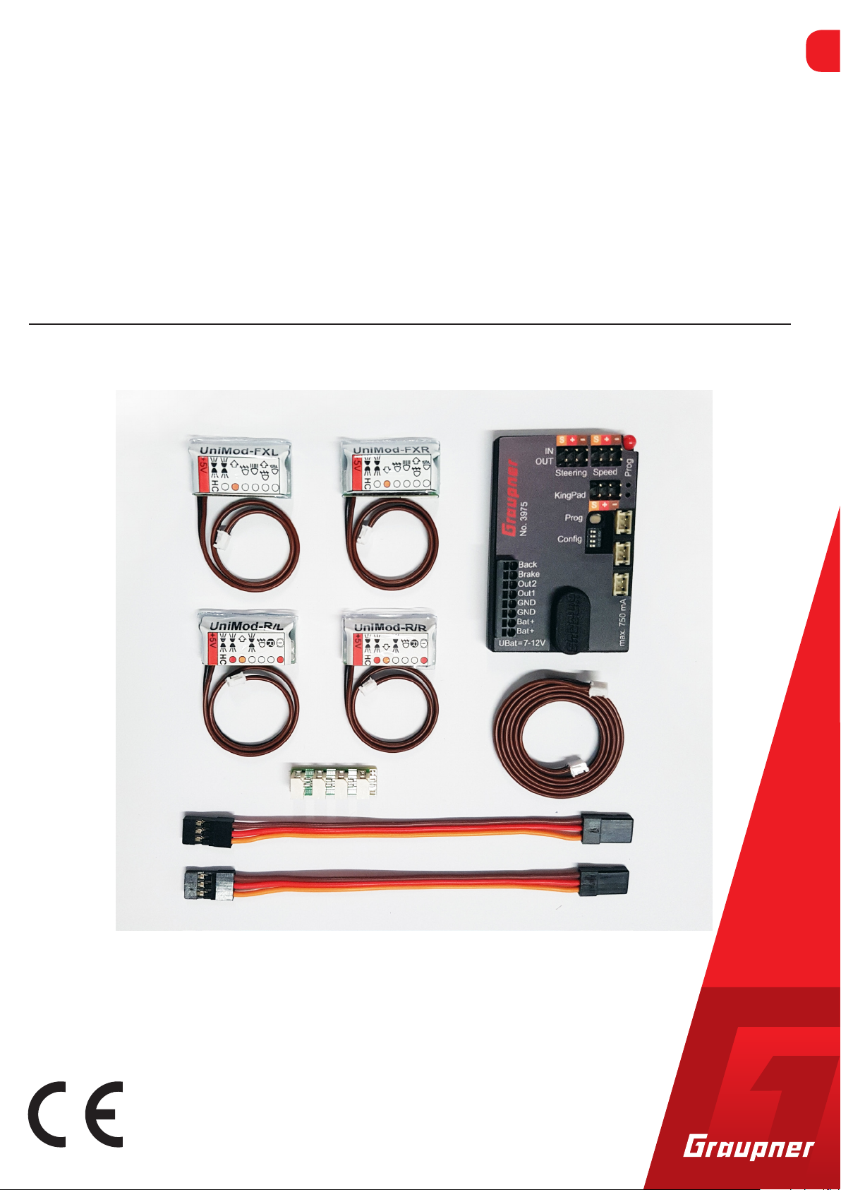
Package content
Required accessories
Kingbus Central Module with connection cable
Universal module for front/rear
Patch cable for steering servo and speed controller
Manual
Graupner Kingpad light module (No. 3974.1 or 3974.32)
LEDs for model lightning.
For the operation of the switching module No.3974.2 the module
IRAM + IR-TX is additionally necessary. For reference and advice:
www.pistenking.de
6 / 16
3975_MP_V1
Page 7

Technical data
Kingbus Central Module
Operating voltage 7,2 to 12 Volt
Power consumption in stand-by 20mA/ max. 750mA
Inputs Battery plus/minus
Drive channel / steering channel
Kingpad
2 light functions
Outputs Battery plus/minus
2x Drive channel / steering
channel
3x Kingbus with max. 750mA
2x switch outputs max 1A each
Dimensions 56 x 36.5 x 11 mm
Attachment in the model glue pad (not included)
Note
You will find the technical description of the required Kingbus and
Adapter on www.graupner.de directly at the product page.
Characteristics
Parking light
Dimmed headlights only with parking light
High beam fixed position with dipped beam.
Flash always available
Automatic cornering light when flashing or steering
Turn signal left / right by setting over Kingpad or with each stee-
ring
Fog lights and rear fog light
Turn signal return via steering channel
Hazard warning lights, rotating beacon
Brake light and reversing light via drive channel
Spotlight front/rear
3975_MP_V1
7 / 16
Page 8

Symbol description
!
!
Safety notes
Always observe the information indicated by this warning sign. Particularly those which are additionally marked with the words CAUTION or WARNING. The signal word WARNING indicates the
potential for serious injury, the signal word CAUTION indicates
possibility of lighter injuries.
The signal word Note indicates potential malfunctions.
Attention indicates potential damages to objects.
General
These safety instructions are intended not only to protect your
own and other people’s safety, but also to protect the product.
Therefore please read this section very carefully before using the
product!
Do not leave the packaging material lying around, this could be
a dangerous toy for children.
Persons, including children, with reduced physical, sensory or
mental capabilities, or lack of experience or knowledge, or not
capable to use safely the transmitter must not use the transmitter without supervision or instruction by a responsible person.
Operation and use of radio-controlled models needs to be
learnt! If you have never driven such a model, then start extra
carefully and make sure to be familiar with the reactions of the
model to the remote control commands. Proceed always responsibly. This also means that you have for your own protection liability insurance.
Protect all equipment from dust, dirt, moisture. All equipment
must be protected from vibration as well as excessive heat or
cold. The models may only be operated remotely in normal
outside temperatures such as from -10°C to +55°C.
8 / 16
3975_MP_V1
Page 9

Notes on environmental protection
P
Disposal notes
If this symbol is on the product, instructions for use or packaging, it
indicates that the product may not be disposed with normal household waste once it has reached the end of its service life. It must be
turned over to a recycling collection point for electric and electronic
apparatus.
Individual markings indicate which materials can be recycled. You
make an important contribution to protection of the environment by
utilizing facilities for reuse, material recycling or other means of
exploiting obsolete equipment.
Batteries must be removed from the unit and disposed of separately
at an appropriate collection point. Please inquire with local authorities about the responsible waste collection locations.
Care and maintenance
Notes on care
The product does not need any maintenance, it works so as it is
without any special care. In your own interest please protect the
model from dust, dirty and humidity!
Warranty certificate
The Graupner, Henriettenstrassee 96, 73230 Kirchheim/Teck grants
from the date of purchase of this product for a period of 24 months.
The warranty applies only to the material or operational defects
already existing when you purchased the item. Damage due to
misuse, wear, overloading, incorrect accessories or improper handling are excluded from the guarantee. The legal rights and claims are
not affected by this guarantee. Please check exactly defects before a
claim or send the product, because we have to ask you to pay shipping costs if the item is free from defects.
The present construction or user manual is for informational purposes only and may be changed without prior notice. The current version can be found on the Internet at
vant product page. In addition, the company
responsibility or liability for any errors or inaccuracies that may
appear in construction or operation manuals.
Not liable for printing errors.
www.graupner.de on the rele-
Graupner has no
3975_MP_V1
9 / 16
Page 10

Declaration of conformity
Product description
Kingbus Central Module
Graupner/SJ declares that the product is conform to EU norms.
WEEE-Reg.-Nr.: DE 42466037
The Kingbus is a two-wire bus system that allows multiple light functions through just two wires. The power supply of the light modules is also ensured via these two wires.
The central module receives the desired lighting functions, evaluates them and sends them via the Kingbus to the light modules.
This item has been tested in accordance with EU directives and
complies with the legal requirements.
Rückfahrlicht
Bremslicht
Ausgang RKL
Ausgang Standlicht
Masse (GND)
Masse (GND)
erie Plus
Ba
erie Plus
Ba
Lenkung:
Eingang (IN)
Ausgang(OUT)
Fahrregler:
1x Eingang (IN)
1x Ausgang (OUT)
1x Zusatzausgang!!!
Montage- und Programmiernadel
Programmier-LED
(gelb)
Kingbus Status LED
(rot)
Kingbus Ausgänge
10 / 16
Needle
Cable
3975_MP_V1
Page 11

Supply voltage Please note that the KBZM may only be supplied with
filtered DC voltage from a power supply unit or with a
battery / rechargeable battery!
Connection terminals
The spring-loaded terminals can be operated with the supplied
needle.
Insert the needle into the rectangular opening and press down
approx. 5mm
The clamp opens
Slide the stripped cable (approx. 5mm) into the round hole until
it stops
Carefully remove the pin -> terminal closes
Check cable for tightness
When not in use, put the needle back in the housing! TIP: Best
suitable flexible, twisted, non-tinned cables from 0.08mm² to
1.0mm²!
Power supply
Servo inputs
Connection options
Connect a voltage source of 7 - 12 V to Bat.Plus and ground (GND).
The two inputs (plus and ground) are each internally "jumpered" and
can be used for other purposes (e.g., RKLs to Out2)
In order to be able to determine the direction and the change in
direction, the signals of the speed controller and the steering servo
are required. Use the supplied servo patch cables to connect the
central module (Speed IN and Steering IN) to the corresponding outputs on the receiver.
Speed controller and steering servo are now connected to the KBCM!
(Speed and Steering OUT)
Another module can be connected to the third output (eg audible
reverse warning) The central module acts as a Y-cable here.
Single inputs: If you have a speed controller with cruise control function (K40, M24, K20, .. from Servonaut), you can continue to use it.
The reversing lights and brake light are connected via the two "Back"
and "Brake" terminals. The remaining lighting functions can still be
switched via the external lighting system. To do this, connect the
light outputs of your light module / speed controller to the two
inputs on the KBCM. To each input is assigned a light function!
3975_MP_V1
IMPORTANT! If the ground of the light module and the Kingbus central module are not the same (different batteries), a ground connec-
11 / 16
Page 12

Light modules
Prog-Taster
1 Lenkkanal revers
2 Fahrkanal revers
3 Blinken bei Kurvenfahrt
First use
Adjustment and servo reverse
tion must be made. For this purpose, the ground terminals GND can
be used.
Install your light modules in the model and connect them to one of
the three Kingbus outputs on the KBCM. On a bus it does not matter
how and where you connect which module! The extension cable is
suitable for wiring the rear lights. The system can be expanded with
the various distributors and extension cables.
After everything is properly connected and wired, you can turn the
power on. The red and yellow LEDs should be constantly lit. If this is
not the case, check the wiring for any short circuits.
For the very first commissioning, you must initialize the central
module. The sticks of the remote control must be in the middle position! Press the white Prog button for more than 2 seconds until the
yellow LED flashes once each second.
If you have a Kingpad, press each key once in a row. (See also Kingpad's manual!) As a confirmation of a recognized key, the yellow LED
remains off also if pushed. After releasing it flashes again!
After the last key, the central module automatically returns from
programming mode to normal mode.
If you do not have a Kingpad, simply press the Prog button again and
the module will return to normal mode. The zero positions for driving and steering are thus programmed.
If the drive and steering movements do not match the lighting (turn
signal and reversing light), the channels can be reversed using the
Config switches 1 and 2.
4 curve lights off
Outputs
12 / 16
The outputs Out1 and Out2 can be used to control additional functions. The outputs switch to ground when activated.
3975_MP_V1
Page 13

Demo mode
Connection example: all-round light bars
Rotating light: black
Parking light: white
Plus pole: red
The Kingbus central module can play a demonstration of the light
controls by briefly tapping the Prog button (less than a second). This
can be used for example to make the model more visible at exhibitions. Remote control is not necessary for this mode! Press the Prog
button again briefly to stop the demo mode.
Connection diagram universal module front
Technical data
Operating voltage: 5 Volt via Kingbus
Connection cable: 150mm, Kingbus connector
Dimensions: 27 x 15 x 8mm
Note
The Uni-Mod is equipped with a spring-loaded terminal. The procedure for connecting the cables is described below:
Insert the connection pin into the rectangular opening (notice-
able resistance must be overcome, terminal opens)
Insert the cable into the round hole until it stops
Carefully remove the pin
Check cable for tightness
3975_MP_V1
13 / 16
Page 14

Legend universal modules
Abblendlicht
Kurvenlicht
Fernlicht
Nebelscheinwerfer
Blinker rechts
Standlicht
The circular dot next to each icon indicates the color of the LED to
be connected. It can be connected per output 1 LED directly (without
series resistor)!
If several LEDs are connected to a normal output, they will not light
up so much. The Uni-Mod does not take any damage!
HC outputs have no resistor! This must be calculated accordingly for
5Volt operating voltage!
Dimmed headlights
Curve lights
High beam
Fog lights
Blinker right
Parking light
Parking light HC (max. 100mAh)
Plus pole together
Brake light
Reversing lights
Rear fog lights
Parking light (position lights)
Blinker right
Parking light
14 / 16
Parking light HC (max. 100mAh)
Plus pole together
3975_MP_V1
Page 15

Symbol für LED in Verdrahtungsplan
Symbol für Widerstand in Verdrahtungsplan
Konkret: 1 K-Ohm (1000 Ohm)
Anschlussstifte, Minuspol kurz, Pluspol lang
Wiring diagram universal modules
3975_MP_V1
15 / 16
Page 16

 Loading...