

Page 1
Manual
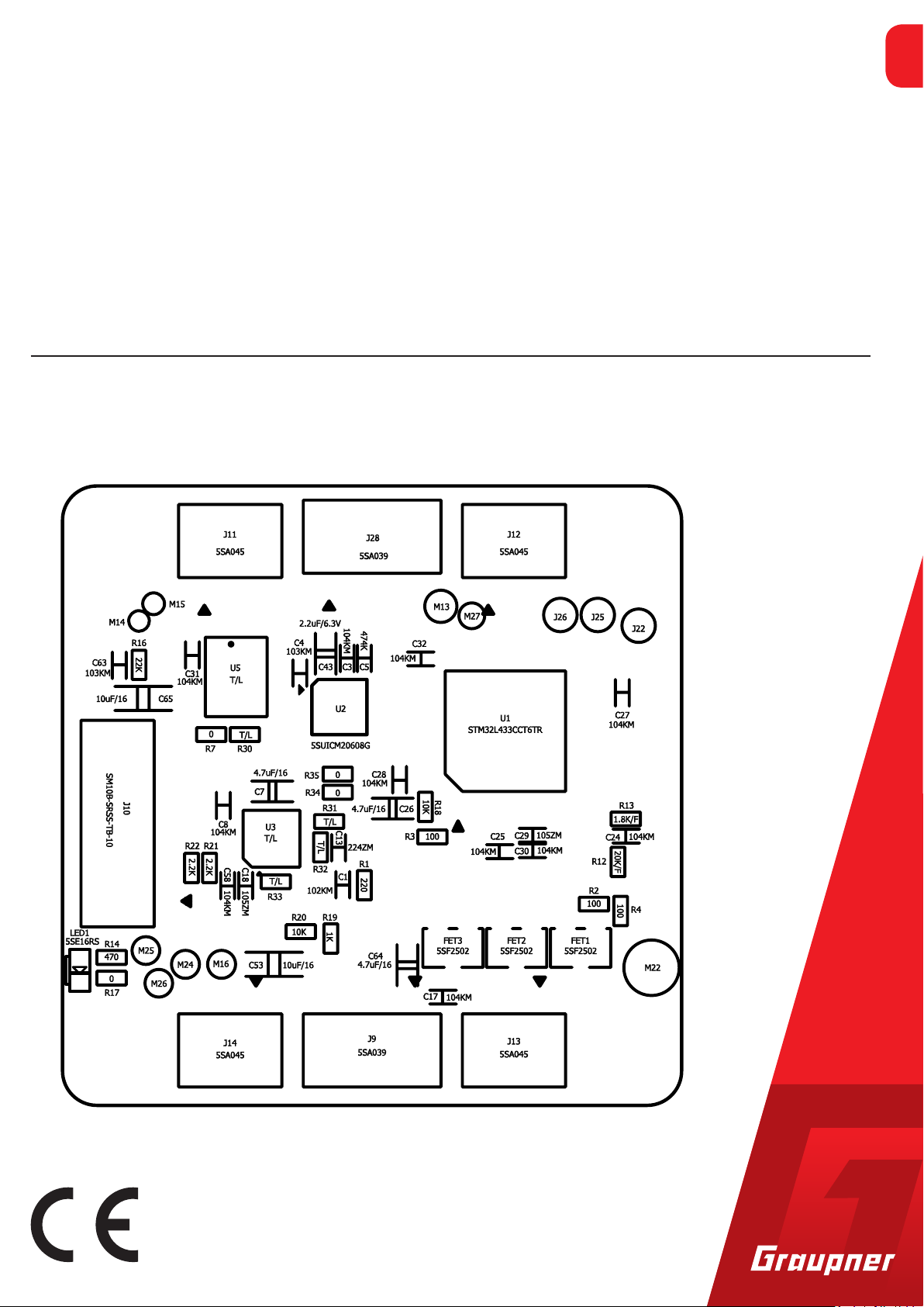
AIO Copter Flight Control
AIO Copter Flight Control with copter firmware Q06
No. S1038 w/out altitude sensor, w/out magnetometer; S1039 with altitude sensor and magnetometer for GPS
EN
Copyright © Graupner/SJ GmbH
Page 2

2 / 32
S1035_Falcon_12_Q06_V1sh
Page 3

Index
Introduction ......................................................................................4
Service centre ...................................................................................4
Intended use ....................................................................................5
Target group .................................................................................5
Package content ................................................................................5
Technical data ...................................................................................6
Symbol description ...........................................................................6
Safety notes ......................................................................................6
For your safety by handling the transmitter and the receiver .......7
For your safety by handling the batteries ......................................8
Installing the AIO FC: ........................................................................9
Connecting the RC components of the copter ...............................9
Connection socket J10 "Telemetry/Update/Waypoints" ............9
Connection socket J9 "FPV transmitter"......................................9
Connection socket J11-J14 "RGB-LEDs" ......................................9
connection socket J28 or Pin lines "ESC" .....................................9
Connection socket J11-J14 "RGB-LEDs" ......................................9
Connection socket J27 "CAM POWER“ ........................................9
binding .............................................................................................12
Transmitter presettings ..................................................................13
Flight mode ...................................................................................13
Auto-flip function on channel 6 ....................................................16
"Telemetry" menu ..........................................................................16
SETTING & DATA VIEW ..................................................................16
Receiver display .........................................................................16
ROLL/NICK Display .....................................................................18
YAW Display ................................................................................19
MULTIC. AUTOPILOT (only by S1039 with GPS #33602) ...........20
MULTIC. AUTOPILOT (only by S1039 with GPS #33602) ...........21
BASIC Display ..............................................................................22
AXIS ASSIGNMENT .....................................................................26
Care and maintenance ...................................................................28
Warranty .........................................................................................28
S1035_Falcon_12_Q06_V1sh
3 / 32
Page 4
Introduction
Thank you very much for purchasing a Graupner AIO FC.
Read this manual carefully to achieve the best results with your HoTT
system and first of all to safely control your models. If you experience
any trouble during operation, take the instructions to help or ask
your dealer or Graupner Service Centre.
Due to technical changes, the information may be changed in this
manual without prior notice. Be always updated by checking periodically on our website, www.graupner.de to be always uptodate with
the products and firmwares.
This product complies with national and European legal requirements.
To maintain this condition and to ensure safe operation, you must
read and follow this user manual and all the safety notes before
using the product and you have to respect those notes also for future
use!
Note
This manual is part of that product. It contains important information concerning operation and handling. Keep these instructions for
future reference and give it to third person in case you gave the
product.
Service centre
Graupner Central Service
Graupner/SJ GmbH
Henriettenstraße 96
D-73230 Kirchheim/Teck
Graupner USA
3941 Park Dr Suite 20-571
El Dorado Hills, CA 95762
Graupner in Internet For the service centers outside Germany please refer to our web site
www.graupner.de.
Servicehotline
(+49) (0)7021/722-130
Monday - Thursday:
9:15 am - 4:00 pm
Friday:
9:15 am - 1:00 pm
service@graupner.de
Website: www.graupnerusa.com
Phone: +1 855-572-4746
Email:service@graupnerusa.com
4 / 32
S1035_Falcon_12_Q06_V1sh
Page 5

Intended use
The AIO FC should only be used for the purpose specified by the
manufacturer for operation of remote controlled copter models
without passengers. Any other type of use is impermissible and may
cause significant property damage and/or personal injury. No warranty or liability is therefore offered for any improper use not covered by these provisions.
In addition, it is explicitly pointed out that you must inform yourself
about the laws and regulations applicable at your respective starting
point before starting the remote control operation. Such conditions
may differ from state to state, but this must be followed in every
case.
Notes
•
• In general, it should not be forbidden to fly over airfields, factories, nature reserves, built-up areas, etc.
• Where designated no-fly zones are located, and which in no way
affect them, it can be determined, for example, using the "AirMap" app.
Target group
Package content
Read through this entire manual before you attempt to install or use
the receiver.
The item is not a toy. It is not suitable for children under 14. The
installation and operation of the receiver must be performed by
experienced modellers. If you do not have sufficient knowledge
about dealing with radio-controlled models, please contact an experienced modeller or a model club.
• S1038 or S1039 AIO Copter Flight Control
• Manual
S1035_Falcon_12_Q06_V1sh
5 / 32
Page 6
Technical data
!
!
Symbol description
Antenna
Operating voltage (2.5) 3.6 ... 15,2 V
Frequency range 2400 ... 2483.5 MHz
Modulation 2.4 GHz FHSS
Current consumption approx.
Temperature range -15 … +70°C
Dimensions approx. 36 x 36 x 10 mm
Weight approx. 9 g
Always observe the information indicated by these warning signs.
Particularly those which are additionally marked with the words
CAUTION or WARNING.
1x 145 mm,
of which the last 30 mm active
70 mA
Safety notes
The signal word WARNING indicates the potential for serious injury,
the signal word CAUTION indicates possibility of lighter injuries.
The signal word Note indicates potential malfunctions.
Attention indicates potential damages to objects.
These safety instructions are intended not only to protect the product, but also for your own and other people’s safety. Therefore please
read this section very carefully before using the product!
• Do not leave the packaging material lying around, this could be a
dangerous toy for children.
• Persons, including children, with reduced physical, sensory or
mental capabilities, or lack of experience or knowledge, or not
capable to use safely the receiver must not use the receiver without supervision or instruction by a responsible person.
• Operation and use of radio-controlled models needs to be learnt!
If you have never driven such a model, then start extra carefully
and make sure to be familiar with the reactions of the model to
the remote control commands. Proceed responsibly.
6 / 32
S1035_Falcon_12_Q06_V1sh
Page 7
• First, always perform a range and function test on the ground (to
!
!
do so, hold your model tight), before you use your model. Repeat
the test with running motor and with short throttle bursts.
• Only use the components and spare parts that we recommend.
Always use matching, original Graupner plug-in connections of
the same design and material.
• Make sure that all of the plug-in connections are tight. When disconnecting the plug-in connections, do not pull the cables.
• Protect the AIO FC from dust, dirt, moisture and foreign parts. Do
not expose it to vibrations or to extreme heath or cold. The models may only be operated remotely in normal outside temperatures such as from -10°C to +55°C.
• Always use all your HoTT components only with the latest firmware version.
• If you have questions which cannot be answered by the operating manual, please contact us or another expert in the field.
For your safety by handling the transmitter and the receiver
WARNING
Also while programming the transmitter, make sure that a connected motor cannot accidentally start. Disconnect the fuel supply or drive battery beforehand.
CAUTION
Avoid every kind of short-circuit in all sockets of the transmitter!
Risk of fire! Use only the suitable connectors. In no case the electronic component of the transmitter or of the receiver may be
changed or modified. Due to licensing reasons, any reconstruction
and/or modification of the product is prohibited.
Note
During transport protect the model and the transmitter from damages.
S1035_Falcon_12_Q06_V1sh
7 / 32
Page 8

For your safety by handling the batteries
!
CAUTION
• Protect the batteries from dust, dirt, moisture, heat and vibrations. Only use in dry locations.
• Do not use any damaged battery.
• Batteries may not be heated, burned, short-circuited.
• If handled improperly, there is a danger of fire, explosion, irritation and burns.
• Leaked electrolyte is caustic and should not be touched or
come into contact with your eyes. In case of emergency, rinse
with a large quantity of water and consult a Med. Doctor.
• Stock the batteries in dry and fresh conditions.
• Dispose of the battery in the proper disposal centers.
8 / 32
S1035_Falcon_12_Q06_V1sh
Page 9

Installing the AIO FC:
The AIO FC must be mounted with its lower surface parallel to the
chassis using the rubber buffers and M3 screws.
The AIO FC must be protected against dust, splash water, etc. in the
model. But do not pack your AIO FC too airtight so that it does not
overheat during operation and the height sensor on the S1039 can
work properly.
The cables may not be wound around antenna or run next to it. Make
sure that the cables cannot shift to lie directly adjacent to antenna
during flight.
In the case of carbon fibre chassis, at least the last 35 mm of the
antennas shall be routed outside.
Connecting the RC components of the copter
Insert the connection cable of the ESCs of the copter, which must be
connected to the receiver, with the black or brown cable upwards
into the connector strip of the receiver, as shown in the illustration
on the left. The polarity of the plug-in system cannot be reversed. Do
not apply force. The servo connections of the Graupner-HoTT
receiver are numbered. Only use speed controllers that are multi-
shot capable to connect the motors.
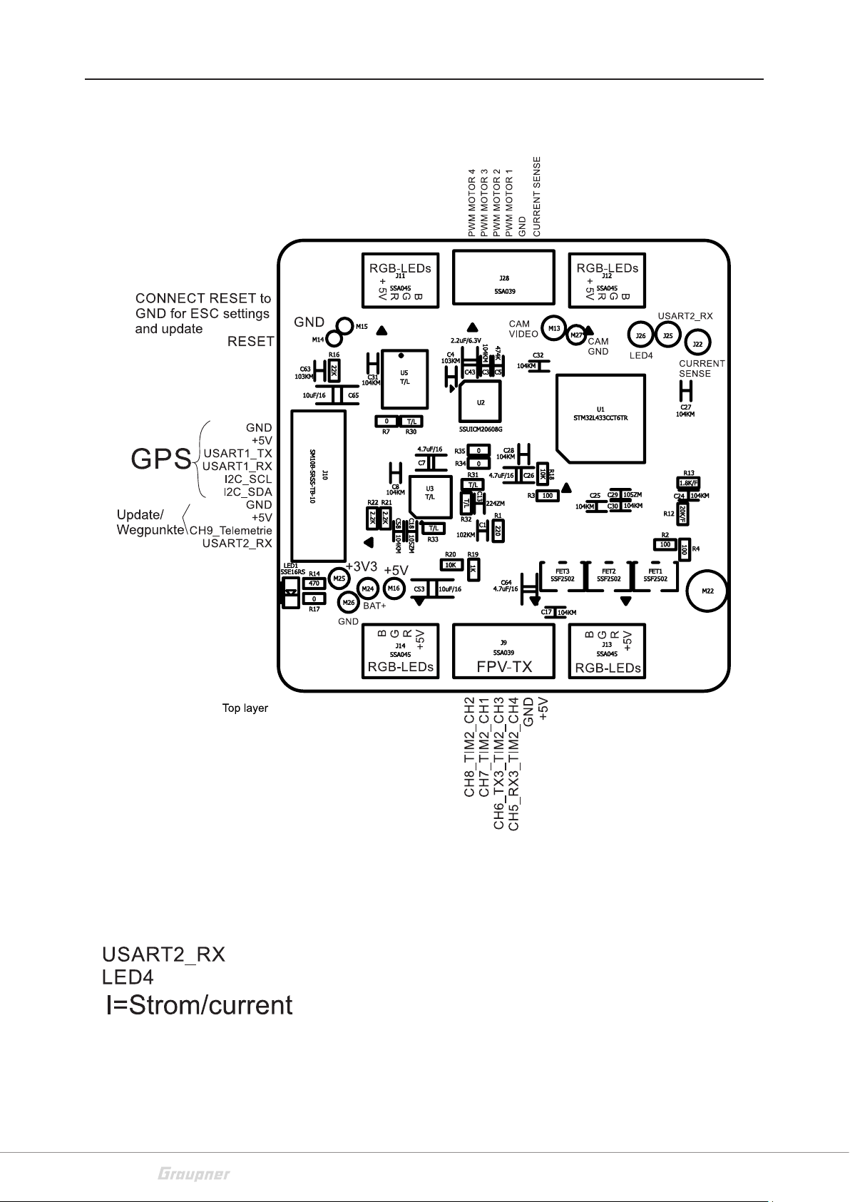
Connection socket J10 "Telemetry/Update/Waypoints"
If required, the optional GPS module #33602 can be connected to
the socket labelled "J10". In addition, the receiver updates are performed on this socket.
Connection socket J9 "FPV transmitter"
If necessary, the FPV transmitter # is connected to the socket labelled
"J9".
Connection socket J11-J14 "RGB-LEDs"
If required, the optional RGB LED PCBs are connected to sockets
labelled "J11-J14".
connection socket J28 or Pin lines "ESC"
The 4in1 ESC 7242.4 is connected to the sockets labelled "J?". The
4in1 ESCs # S3087 or # S3088 are connected to the double row pin
headers J23 / 24.
Connection socket J11-J14 "RGB-LEDs"
If required, the optional RGB LED PCBs are connected to sockets
labelled "J11-J14".
Connection socket J27 "CAM POWER“
The FPV camera is connected to this socket
S1035_Falcon_12_Q06_V1sh
9 / 32
Page 10
10 / 32
S1035_Falcon_12_Q06_V1sh
Page 11

S1035_Falcon_12_Q06_V1sh
11 / 32
Page 12

binding
To establish a connection with the transmitter, the Graupner HoTT
receiver must first be "bound" to at least one model memory in "its"
Graupner HoTT transmitter. This process is generally called "binding". However, the available methods to be used are not always the
same, so the following step-by-step instructions apply only to binding a HoTT AIO FC to any transmitter:
Binding step-by-step
• If the AIO FC is already bound to a specific transmitter and this
binding should be maintained, the transmitter should ideally be
switched on before the receiver. At the latest, however, within
approximately 15 seconds from the moment when the receiver
is switched on, the red LED of the receiver is constantly on.
Attention
As soon as the LED starts to flash, the AIO FC is in bind mode.
From this point on there is the risk that the AIO FC unintentionally binds to a transmitter, which is casually in bind mode at the
same time, whereupon the model can run uncontrolled at any
time. The distance between transmitter and AIO FC should be at
least 0.5 m, otherwise the receiver of the AIO FC can be overdriven.
• If the AIO FC is unbound or it should be bound to another transmitter or only the model memory has to be changed than the
previous one, proceed as follows:
1. Prepare the transmitter or model memory to be bound accord-
ing to the instructions for binding.
2. Switch on the copter power supply.
3. The LED of the AIO FC lights constantly red.
4. Approximately 15 seconds after the AIO FC is switched on, its
red LED starts to flash, indicating that the AIO FC is now in
bind mode.
5. Start the transmitter-side binding according to the instruc-
tions of the transmitter.
6. If the red LED of the AIO FC goes out within about three sec-
onds, the binding process has been completed successfully.
7. Your transmitter/AIO FC combination is ready for operation.
8. If the LED on the AIO FC remains still red, the "binding" has
failed. Change the positions of the associated antennas and
try the entire procedure again.
12 / 32
S1035_Falcon_12_Q06_V1sh
Page 13

Transmitter presettings
Flight mode
Depending on the bandwidth of the model type selection of the
transmitter used, either the model type "Copter" or alternatively a
"Fixed-wing model" should be selected. Some of the current HoTT
transmitters are even shipped with preconfigured model memory.
According to the transmitter instructions, the appropriate control
mode and, if necessary, "motor front / rear" must be set. Usually
"backwards" so that the channel 1 indicator in the servo display indicates -100% in the "motor off" position of the "motor / pitch control
stick".
S1038: Flight mode has to be set to channel 5. To do this, program a
2-way switch in the "Control settings" menu on Channel 5 as follows:
S1039: Flight mode has to be set to channel 5. To do this, according
to the transmitter instructions, program a 3-way switch in the »Transmitter setting« menu on channel 5 as follows on the next page:
Attitude mode
E5
E6
E7
E8 +100%
1
3
5
7
E5
E6
E7
E8 +100%
1
3
5
7
free
free
free
–100 %
+
free
free
free
+100 %
+
3
0%
0%
0%
3
0%
0%
0%
+100%
+100%
+100%
2
4
+100 %
6
8
+100%
+100%
+100%
2
4
+100 %
6
8
+100%
+100%
+100%
+100%
trv
0%
0%
0%
+100%
+100%
+100%
+100%
trv
0%
0%
0%
The stick movements acts directly proportionally to Roll and Nick. In
the attitude mode, the maximum inclination angle is limited to
approx. 50° at 100% of the stick travel.
The attitude mode is active as long as the bar of channel 5 is on the
+
left of +49% in the »Servo display«.
(The -100% shown on the left are based on the switch programming
above.)
Flight mode suggested for beginners.
Rate mode
In this mode, the rate is determined by the rash of the stick without
inclination limit. In this aerobatic mode rolls and loops are possible.
The rate mode is active as soon as the bar of channel 5 in the display
»Servo Display« is +50% or higher.
+
(The -100% shown on the left are based on the switch programming
above.)
Not suitable for beginners.
S1035_Falcon_12_Q06_V1sh
13 / 32
Page 14

Only S1038:
1
3
5
7
1
3
5
7
E5
SW6/7
E6
E7
free
free
E8
+100 %
+
SW4/5
E5
SW6/7
E6
E7
free
E8
+100 %
+
0%
0%
0%
0%
0%
0%
3
3
+100%
+100%
+100%
+100%
Trvl
2
4
+100 %
6
8
+100%
+100%
+100%
+100%
Trvl
2
4
+100 %
6
8
+100%
+125%
+100%
+100%
+
0%
0%
0%
+100%
+100%
+100%
+100%
+
0%
0%
0%
C5 = 0% (Attitude mode) and C6 = 125% = Auto-flip mode
C5 = 0% (Attitude mode) and C6 = 100% = switching between the
FPV transmitter channels, only when the motors are switched off.
Only S1039 and only with GPS 33602: Autopilot mode
C5 = -100% and C6 = 0% = Autopilot mode (with GPS), control of the
copter speed. Neutral stick position means GPS position and altitude
hold.
If you start in autopilot mode, the height is maintained at the middle
of the stick (0%).
If you start in Rate or Attitude mode and then switch to the autopilot mode, the throttle position when switching the mode is the stick
position at which the altitude is maintained.
C5 = -100% and C6 = -100% = Come back home to the start point
(with GPS)
C5 = -100% and C6 = +100% = Departure from previously programmed waypoints (in preparation)
1
3
5
7
SW4/5
E5
SW6/7
E6
E7
free
E8
+100 %
+
0%
0%
0%
3
+100%
+100%
+100%
+100%
Trvl
2
4
+100 %
6
8
+100%
+100%
+100%
+100%
+
0%
0%
0%
Note
When the GPS is connected, the copter only allows the motors to be
switched on if 6 GPS satellites or more are found.
While searching for GPS satellites, an HD camera should be off. If
more than 8 satellites have been found, the HD camera can be
switched on. Check if there are more than 6 satellites in the GPS Copter telemetry display. The Autopilot and Come back home mode only
work in the configuration of how the compass was calibrated (eg
with HD camera on. If you change the airfield, the compass should
be recalibrated.
Only S1039: Carefree GPS mode
C5 = -100% and C6 = 0%, so as C7 = +100% = Carefree control mode
In Carefree control mode, the flight direction is saved when activated, even if the Copter is then rotated by yaw command.
This facilitates the control of the copter in difficult visibility conditions.
C5 = -100% and C6 = 0%, so as C7 -100%....+50% = normal control
mode
14 / 32
S1035_Falcon_12_Q06_V1sh
Page 15

Fail-Safe settings
FAIL SAFE
Pos
hold
1 2 3
Delay 0.25s STO
Mod.Name
Control mode
Motor on CH1
M.Stop
Timers 0:00 –––
–125% +100%
5
4
ALPHA 110
7 8
6
1
idle rear
We recommend to set Channel 1 and Channel 5 to "Pos" according
to the transmitter instructions and to put the pitch control stick in
the motor OFF position before storing the fail-safe settings and to
set the attitude / rate mode switch to the "Attitude mode" position
so that the attitude mode is active in fail-safe situations and the
motors stop. When using the # S1039 AIO FC with GPS, it is recommended to set C1 on Hold and C5 and 6 on Pos, in the Come back
home position, so that the copter will fly back to the starting position
if there is a loss of signal. Please note that when the signal is received
again, the set mode will become active again and the pilot will have
to take again the control.
Throttle Cut
For safety reasons, a motor stop switch must always be programmed
on the transmitter side according to the transmitter instructions.
1
Only when this is placed into the appropriate position, an undesired
start of the motors is reliably prevented.
But in order to be able to switch off the motors also in the Acro 3D
mode, another mixer has to be programmed. Namely, if the copter
is operated in the acro 3D mode with the rate mode enabled, the
motor stop function would not shut off the motors, but set them to
"full power backwards". To prevent this, the mixer must be programmed in such a way that switching the motor stop switch to the
motor OFF position also switches to the attitude mode, in which the
stop of all motors is ensured.
M1
M2
M3
M4
M5
MIX 1
Trv+100%+100%
Offset
STO
Type
+100%
S
??
??
??
??
from
SEL
5
??
??
??
??
to
S 5
Programming step-by-step
9. Program a linear mixer of "S => 5" according to the transmitter
=
1
instructions.
10. Assign to this mixer the same switch with the same switching
direction, which switches to the attitude mode.
11. Change to the setting page of the mixer.
12. Set the "travel" symmetrically to +100%.
13. Change to the line "Offset".
14. Now either set the offset value manually to +100% or set the
motor stop switch to "motor ON" and then push the ENT key. In
both cases, however, the adjacent picture must arise.
S1035_Falcon_12_Q06_V1sh
15 / 32
Page 16

Auto-flip function on channel 6
ALARM Capac. 400mAh
E5
E6
E7
E8
3
SW6/7
free
free
+100%
+100%
+100%
+100%
Trvl
+100%
+125%
+100%
+100%
+
SETTING & DATA VIEW
If the copter is in attitude mode, the automatic flip function can easily trigger a flip of the copter.
The auto-flip function is activated via a key switch assigned to channel 6. This has to be programmed on channel 6 in the "Control setting" menu of the transmitter and then, with the button held down,
the asymmetrical travel must be set to +125%.
If this button is pressed, the servo position of channel 6 exceeds the
value of 111% and the autoflip function is thus "armed" for 5 seconds. As soon as the roll or pitch control stick is moved over more
than 50% of the stick travel within this time, the copter will automatically flip in that direction.
Note
After the flip, position deviations in the range <10 ° are possible.
"Telemetry" menu
TELEMETRY
SETTING & DATA VIEW
SENSOR
DISPLAY RF STATUS
SELECT ANNOUNCE
RX DATA ON
ALARM SETTINGS
Receiver display
RECEIVER Q.06
LANGUAGE: English
ALARM VOLT: 3.8V
ALARM TEMP: 70°C
Altitude max: 100m
PERIOD: 20ms
Video chennel R3
The basic handling of the "Telemetry" menu is described in the
respective transmitter instructions or the instructions of the SmartBox. By way of derogation, only in certain receivers the menu structure is summarized under the generic term "setting & data view".
These instructions also provide information on how to access this
menu. Change accordingly to the first setting page of the AIO FC.
Note
The setting values shown in the following display illustrations always
show the standard values.
LANGUAGE
In the "Language" line you can set the display language in the receiver
menu.
The choices are: German, English, French, Italian, Spanish
ALARM VOLT
If the receiver voltage falls below the set value, a low-voltage warning is generated by the transmitter in the form of a "sound-declining
alarm tone" or the "receiver voltage" speech output message.
16 / 32
S1035_Falcon_12_Q06_V1sh
Page 17

ALARM TEMP
If the receiver temperature exceeds the set temperature, a warning
is generated by the transmitter in the form of a "3-step sound-climbing alarm tone" or the "receiver temperature" speech output message.
Max. altitude
If the copter exceeds the set max. height, the transmitter will warn
you with "max. height "or, by transmitters without speech output,
with a corresponding tone sequence.
only with S1039: In autopilot mode, the altitude is limited to the set
altitude.
PERIOD
currently no function
Note
Changing the cycle time is only necessary when installing servos for
additional functions.
Video channel:
If the video transmitter # 16570.123 is connected to the connector
J9, then the video channel can be set via this menu item.
only with S1038: The video channel can also be switched on by pressing the C6 (+ 100%) for 2 seconds. This is only possible when the
motors are switched off.
ALARM Capac.
If the used battery capacity exceeds the set value, a warning message "Capacity" is output in the transmitter or a corresponding
sequence of tones by transmitters without voice output. In this case
you should return to the starting point or, if this is no longer possible, land safely.
S1035_Falcon_12_Q06_V1sh
17 / 32
Page 18

ROLL/NICK Display
MULTICOPTER RO/NI
ROLL/NICK P 50
ROLL/NICK D 50
DAMPING 40
ROLL FACTOR % 95
POWER2SENS. 80
R/N DYNAMIC 70
––ATTITUDE MODE––
ROLL/NICK I 80
AGILITY 3
––RATE MODE––
R/N RATE I 40
RATE 70
The control is based on the PID principle, where the "P" stands for
"proportional", the "I" for "integral" and the "D" for "digital". In short
...
... the deviation from the setpoint proportional to the manipulated
variable has an effect at the P value.
... the existing control deviation is continuously summed up at the I
value and then acts on the manipulated variable via the I value.
... the differential component only takes into account the speed of
the control deviation and then acts on the control accordingly via the
D component.
ROLL/NICK P
This parameter determines the tilting behaviour of the copter during
the maximum climb.
In order to prevent tilting at full climbing power in the end, this
parameter must be increased in steps of 5 until a medium-fast tilting
occurs. Subsequently, this value is to be adjusted in individual steps
until the tilting has disappeared.
ROLL/NICK D
This parameter determines the tilting behaviour of the roll / pitch
function of the copter.
As described above, this parameter must be adjusted until the Multicopter engages exactly over Roll and Nick. A too high value leads to
very rapid oscillations.
DAMPING
The damping factor should be set as low as possible, but as high as
necessary, so that the PID control can operate optimally. To prevent
oscillations or tilting, the damping should be <30. To dampen motor
or prop vibration and prevent motor noise, higher values may be
needed. These can be adjusted at the beginning in steps of 10 and
then finer.
ROLL FACTOR %
Set the Roll setting as percent value of the overall gain. For symmetrical copters, the value should normally be left at 100. If, because of
its gravity centre, the Copter is more agile on the Roll axis than on
the Nick axis, then you can change here the roll factor. In the Graupner
ALPHA RACE 250 Q this value is set about 65%.
18 / 32
POWER 2SENS.
Very strong drives can lead to oscillating at full throttle. This parameter allows you to set a kind of gyro suppression. Higher values result
in an increased suppression towards full throttle.
S1035_Falcon_12_Q06_V1sh
Page 19

–– ATTITUDE MODE ––
–– RATE MODE ––
R/N DYNAMIC
Higher dynamic values provide a more direct feel for the flight (3D
flight 50 ... 100), lower dynamic values for smoother flight recordings, rounder freestyle flying and races (30 ... 50).
ROLL/NICK I
Set the I component of the Attitude mode. At too low values of Copter tilts slowly. If it stops after a roll or pitch command and “oscillates”, the value must be reduced.
AGILITY
This value determines how fast a change of position is made.
R/N RATE I
Sets the I component of the rotation in rate mode. At too low values
of Copter tilts slowly. If it stops after a roll or pitch command and
“oscillates”, the value must be reduced.
YAW Display
MULTICOPTER YAW
YAW P 40
YAW I 25
YAW D 40
RATE 70
YAW DYNAMIC 75
RATE
This value sets the maximum potential rate in Rate mode.
The general comments on PID control in the description of the roll /
pitch display are also applicable here.
YAW P
The P factor is responsible for the snap to yaw. Higher values result
in a faster stop. At too high P-values the copter starts to “swing”. In
such cases, the value must be reduced again.
YAW I
The I-factor ensures constant rotations. Start with low values and
only increase them until the rotations are constant. Too high value
cause an oscillation when you stop. Eventually, the motors can start
rotating and thus cause unwanted rising.
S1035_Falcon_12_Q06_V1sh
19 / 32
Page 20

YAW D
MULTIC. AUTOPILOT
ALTITUDE HOLD I 25
ALTITUDE HOLD D 30
ALTITUDE HOLD II 5
POS HOLD P 45
ALTITUDE HOLD P 20
POS HOLD I 5
POS HOLD D 10
POS HOLD II 5
RETURN ALTITUDE 25
The D-factor affects the stopping behaviour in Yaw. In most Copters
a hard D action is necessary. The D component must be set as low
as possible, since it affects the whole system.
RAT E
For beginners we recommend a rate of about 50. For racers and freestyle pilots we recommend a value between 50 and 70.
YAW DYNAMIC
Higher dynamic values provide a more direct feel for the flight (3D
flight 80 ... 100), lower dynamic values for smoother flight recordings, rounder freestyle flying and races (30 ... 80).
MULTIC. AUTOPILOT (only by S1039 with GPS #33602)
ALTITUDE HOLD P
MULTIC. AUTOPILOT
ALTITUDE HOLD P 20
ALTITUDE HOLD I 25
ALTITUDE HOLD D 30
ALTITUDE HOLD II 5
POS HOLD P 45
POS HOLD I 5
POS HOLD D 10
POS HOLD II 5
RETURN ALTITUDE 25
(Factory setting: 20)
The altitude hold P value compensates the climb and descent rate
and must be adjusted so that it is compensated as well as possible.
The copter must under no circumstances swing around the desired
height, otherwise the value must be reduced.
ALTITUDE HOLD I
20 / 32
(Factory setting: 25)
The altitude hold I value compensates for the height difference and
must be set so that it is compensated as well as possible. The copter
must under no circumstances swing around the desired height, otherwise the value must be reduced.
ALTITUDE HOLD D
(Factory setting: 30)
The altitude hold D value compensates the acceleration (wind gusts)
in the height direction and it must be adjusted so that it is compensated as well as possible.
ALTITUDE HOLD II
(Factory setting: 5)
The altitude hold II value compensates for the time-integrated height
difference, so that the desired height is kept as good as possible. This
does not usually have to be adjusted.
POS HOLD P
(Factory setting: 45)
S1035_Falcon_12_Q06_V1sh
Page 21

The POS HOLD P value compensates for the position speed and must
be set to compensate as well as possible. The copter must never circling or overshooting the GPS target position, otherwise the value
must be reduced.
POS HOLD I
(Factory setting: 5)
The POS HOLD I value compensates for the position difference and
must be set to compensate as well as possible. Under no circumstances the copter should oscillate around the GPS target position,
otherwise the value must be reduced or the compass calibration and
voltage calibration have to be repeated.
POS HOLD D
(Factory setting: 10)
The POS HOLD D value compensates the acceleration (wind gusts) of
the GOS position and it must be adjusted so that it is compensated
as well as possible.
MULTIC. AUTOPILOT (only by S1039 with GPS #33602)
MULTIC. AUTOPILOT
ALTITUDE HOLD P 20
ALTITUDE HOLD I 25
ALTITUDE HOLD D 30
ALTITUDE HOLD II 5
POS HOLD P 45
POS HOLD I 5
POS HOLD D 10
POS HOLD II 5
RETURN ALTITUDE 25
POS HOLD II
(Factory setting: 50)
Currently without effect.
The POS HOLD II value compensates for the distance difference integrated on time so that the position setpoint is kept as good as possible. This does not usually have to be adjusted.
RETURN FLIGHT ALTITUDE
(Factory setting: 25)
Determines the return altitude at Coming Home in meters.
S1035_Falcon_12_Q06_V1sh
21 / 32
Page 22

BASIC Display
TYPE
MULTICOPTER BASE
TYPE QUADRO XI
ESC S3087
MODE ACRO 3D
MINPOWER % 5
FREESTYLE MIN
CALIBR.COMPASS No
CALIBR.CURRENT No
The "Type" line defines the basic configuration of the copter. The following selections are available:
QUADRO X QUADRO XI (invers)
1
4
2
3
1
4
2
3
QUADRO +
1
4
3
2
Connect the speed controllers of the motors to the receiver following the proper scheme. The represented motor direction is referred
to the copter seen from the top.
ESC
S3087, S3088, 7242.4
The 4in1 controllers have a built-in power shunt. For correct current
indication, the current connection of the 4in1 controller must be
connected to the S1038 / S1039 and the corresponding 4in1 controller must be selected.
CONTROLLER SETTING
To initialize the controller, the signal of the motor / pitch control stick
of the transmitter is transmitted directly to the speed controller of
the copter.
MODE
CONTROLLER SETTING
To initialize the controller, the signal of the motor / pitch control stick
of the transmitter is transmitted directly to the speed controller of
the copter.
22 / 32
S1035_Falcon_12_Q06_V1sh
Page 23

!
positive full
Throttle travel
Rate mode
Throttle travel
Attitude mode
linear
Min.
linear
negative full
NORMAL
This setting must be used for copters with speed controller without
reverse of the direction of rotation.
ACRO 3D
This setting is reserved for copters whose speed controllers are
equipped with direction reverse.
Note
For safety reason the "Type" and "Mode" changes take effect after
switching off and on the receiver system.
CAUTION
Since the power control operates differently in the rate mode, see
figure on the left, the motors may start rotating more or less when
switching from the attitude mode to the rate mode, depending on
the current position of the pitch stick. Therefore always mount the
propellers immediately before starting the flight operation and
start and land exclusively in "attitude mode".
M1
M2
M3
M4
M5
Type
S
C1
??
??
??
from
zu
5
C1
??
??
??
to
linear up to full
Motor Min.
1
3
During prolonged extreme aerobatics of the copter in Acro 3D
mode (e.g. , sequence> 1min), the receiver may lose its attitude
information and, as a result, the copter may move to an undesired
position when switching to attitude mode. In this situation, the
copter should be in the Rate mode and either it is left quiet for
about 30 seconds or it is landed for a short time, so that the
receiver can readjust the position information again.
Note
If the motors do not stop completely in the attitude mode, so that
the position control is still active and can also serve as a rescue
mode in an emergency, this can be remedied with the aid of a mixer:
Mixer programming step by step
15. Program a same-channel mixer "1 => 1" according to the trans-
=
=
mitter instructions.
16. Assign to this mixer the same switch with the same switching
direction, which switches to the attitude mode.
17. Leave this switch in the ON position.
MIX 2
Trvl –30% 0%
Offset
SYM
S1035_Falcon_12_Q06_V1sh
0%
ASY
C1 C1
18. Change to the setting page of the mixer.
19. Change through "ASY" to the setting field of the "Travel" line.
20. Set the value in the active value field of the "Travel" line to -30%.
23 / 32
Page 24

In the idle position of the throttle / pitch stick, the bar of channel
1 in the "servo display" should now be at about -66%.
MINPOWER %
MULTICOPTER BASE
TYPE QUADRO XI
ESC S3087
MODE ACRO 3D
MINPOWER % 5
FREESTYLE MIN
CALIBR.COMPASS No
CALIBR.CURRENT No
The setting is principally used to prevent the motors shut down in
flight. Adjust so that the motors are running straight. Under no circumstances unnecessarily high set, this would limit the controller
possibilities.
FREESTYLE
The setting basically serves to prevent the I-factor from generating
a vibration.
The higher the value, the more I-vibrations are prevented, but also
the straight-ahead flight is degraded. Values up to max. 20 recommended.
The adjustment range is from 1 ... 100
MIN = disabled
Alternatively, the effect on the I value can also be adjusted by the
transmitter. To do this, a rotary or slider control is assigned to one of
the control channels 5 ... 16 and the remaining settings are left at the
default values. In the value field of the "Freestyle" line, the corresponding channel is then merely to be selected instead of a fixed
value.
Note
If a channel is selected in this line, but no control is assigned in the
transmitter or otherwise it influences its neutral position, the value
"50" in parenthesis is predefined.
Only by #S1039: CALIBR. COMPASS
Note
When using an HD camera, it must be turned on when calibrating
the compass. Otherwise the autopilot mode and
Come back home mode only work with HD camera switched off. If
the autopilot and Come back home functions are used, then the HD
camera must be turned on, since the current of the HD camera also
affects the compass calibration.
If you change the airfield, the compass should be recalibrated. However, the current calibration does not need to be repeated.
24 / 32
S1035_Falcon_12_Q06_V1sh
Page 25

MULTICOPTER BASE
LOGGING 0
MODE ACRO 3D
MINPOWER % 5
FREESTYLE MIN
CALIBR.COMPASS NO
CALIBR.CURRENT NO
CALIBR.POSITION NO
LOGGING 0
MULTIKOPTER BASE
MODE ACRO 3D
MINPOWER % 5
FREESTYLE MIN
CALIBR.COMPASS NO
CALIBR.CURRENT NO
CALIBR.POSITION NO
Activation of the field with SET or ENT.
Set the field to Yes
Deactivate the field again
Now turn the multicopter north pointing slowly twice in a circle on
all axes and then randomly in different directions until No appears.
Then the compass is calibrated.
Only by #S1039: CALIBR. CURRENT
Note
It is advisable to first determine the throttle hovering position and
note it, then swap the propeller and install them in the adjacent
motor, so that the copter is sucked to the ground, instead of lifting.
The attitude control is not active in this mode, so the current calibration must be done on the ground.
The copter must not move during calibration. In addition, the sticks
(except the throttle one) must not be moved during calibration.
The current calibration should be done in calm wind conditions, otherwise the current will fluctuate too much and make the calibration
more difficult.
MULTICOPTER BASE
MODE ACRO 3D
MINPOWER % 5
FREESTYLE MIN
CALIBR.COMPASS NO
CALIBR.CURRENT NO
CALIBR.POSITION NO
LOGGING 0
Activation of the field with SET or ENT.
Set the field to Yes
Deactivate the field again
When display OFF, the motors must be switched off
If the display changes to Min, then please switch the motors to the
Mingas throttle position.
If the display changes to Hover, then please add "Hovering throttle"
until the display changes to "No".
If the copter accidentally or by a control command has rotated on
the yaw axis, the calibration must be repeated.
CALIBR. POSITION
With this option, if necessary, the basic calibration of the acceleration sensors can be readjusted, so that the copter hovers with the
stick and trim to neutral, in attitude mode, precisely horizontally.
To recalibrate, place the copter on an absolutely horizontal surface
and then set the value field to "YES".
As soon as the calibration is completed, the display changes back to
"NO". To accept the calibration that has just been carried out in the
non-volatile memory of the receiver, it is essential to push or tap on
the ENT key.
S1035_Falcon_12_Q06_V1sh
25 / 32
Page 26

AXIS ASSIGNMENT
!
Only by S1039: LOGGING
Logging 0 displays the Euler angles in the Copter telemetry display
and also allows the position display using the Graupner HoTT OSD #
33641 on the FPV screen or in the FPV video goggles.
The other logging functions are exclusively intended for the service.
Note
The gyroscope calibration, required each time the copter is switched
on, takes place as soon as the copter or its receiver is absolutely
quiet. The motors will not start until the calibration is completed.
After approx. 3 seconds in the rest position, several beeps can be
heard from all motors. The number of beeps varies depending on
the speed controller used. These "wiggles" signal that initialisation
has been successful and that calibration is complete.
CAUTION
If the copter is used for long time (>1min) in Acro 3D mode the
receiver can loose its position information and the copter can
move itself out of control. In this case the copter should be left in
the rate mode and hover or land calmly for approx. 30 s, so that
the receiver can track the position again.
AXIS ASSIGNMENT
NEW SETUP NO
ROLL +0
NICK +0
YAW +0
In this display, the gyros and their effective direction are to be determined.
NEW SETUP
After selecting the line "do setup" and changing the value field to
"yes", assign the axes as follows:
Do setup step by step
1. Push or tap on the ENT key
"NO" is displayed inverted.
2. Change the value field to "YES".
3. Push or tap on the ENT key
4. At the transmitter briefly bring the roll control stick to the right
stop.
The display shows the roll axis inverted.
5. Tilt the copter more than 45 degrees to the right.
As soon as the detected axis with the required sign is displayed in
"normal" representation, the axis assignation is completed.
26 / 32
S1035_Falcon_12_Q06_V1sh
Page 27

6. At the transmitter briefly bring the nick control stick to the front
stop.
The display shows the nick axis inverted.
7. Tilt the copter more than 45 degrees to the front.
As soon as the detected axis with the required sign is displayed in
"normal" representation, the axis assignation is completed.
8. At the transmitter briefly bring the yaw control stick to the right
stop.
9. Turn the copter clockwise by more than 45 degrees to the right.
As soon as the detected axis with the required sign is displayed in
"normal" representation, the axis assignation is completed.
The gyros and their operating directions have now been assigned.
Attention
To be on the safe side, the directions of action of the gyroscope settings must be checked.
Check step by step
1. Remove the rotors of the copter.
2. Use the pitch control stick to give approx. 25% "throttle".
All motors run at the same speed.
3. Switch to the attitude mode.
4. Tilt the copter forward.
The front motors must turn faster than back ones.
5. Tilt the copter to one side.
The motors of the side, the "hanging" side must turn faster than
those of the opposite, higher side.
‖ If this is not the case, the entire gyro assignment must be
repeated.
Firmware update
Updates to the receiver’s firmware are made via the receiver connection 5 using a PC running Windows 7 ... 10. You will also need a
USB interface, No. 7168.6, and adapter lead, No. 33565.1, which are
available separately. The adapter cable must be plugged into J10 so
that the first pin on the right remains free.
The programs and files required can be found in the Download area
for the corresponding products at www.graupner.de.
S1035_Falcon_12_Q06_V1sh
Connect the adapter lead to the USB interface. The polarity of the
plug-in system cannot be reversed. Note the small chamfers on the
sides. Do not use force, the plug should click into place easily.
Connect the other end of the adapter lead to the AIO FC's socket
labelled with "J10". The polarity of the plug-in system cannot be
reversed. Do not apply force.
27 / 32
Page 28

The update takes place via the program part "Slowflyer / Gyro
P
Receiver Downloads" of the program "Firmware_Upgrade_gr_Studio" available under "Links". Please follow the notes of the software.
The further procedure is also described in detail in the manual contained in the data package. You can also download these from the
download page of the product at www.graupner.de.
SIMPLIFIED DECLARATION OF CONFORMITY
Graupner/SJ hereby declares that the AIO FC S1038 and S1039
complies with the Directive 2014/53/EU.
The full text of the EU Declaration of Conformity is available at the
following Internet address: www.graupner.deNotes on environ-
mental protection
If this symbol is on the product, instructions for use or packaging, it
indicates that the product may not be disposed with normal household waste once it has reached the end of its service life. It must be
turned over to a recycling collection point for electric and electronic
apparatus.
Care and maintenance
Warranty certificate
Individual markings indicate which materials can be recycled. You
make an important contribution to protection of the environment by
utilizing facilities for reuse, material recycling or other means of
exploiting obsolete equipment.
Batteries must be removed from the unit and disposed of separately
at an appropriate collection point. Please inquire if necessary from
the local authority for the appropriate disposal site.
The product does not need any maintenance. Always protect it
against dust, dirt and moisture.
Clean the product only with a dry cloth (do not use detergent!) lightly
rub.
Graupner/SJ GmbH, Henriettenstrassee 96, 73230 Kirchheim/Teck
grants from the date of purchase of this product for a period of 24
months. The warranty applies only to the material or operational
defects already existing when you purchased the item. Damage due
to misuse, wear, overloading, incorrect accessories or improper handling are excluded from the guarantee. The legal rights and claims
are not affected by this guarantee.
Page 29

Please check exactly defects before a claim or send the product,
because we have to ask you to pay shipping costs if the item is free
from defects.
These operating instruction are exclusively for information purposes
and are subject to change without prior notification. The current
version can be found on the Internet at www.graupner.de on the
relevant product page. In addition, the company Graupner/SJ has
no responsibility or liability for any errors or inaccuracies that may
appear in construction or operation manuals.
Not liable for printing errors.
S1035_Falcon_12_Q06_V1sh
29 / 32
Page 30

FCC Warning :
This device complies with Part 15 of the FCC Rules. Operation is subject to the following
two conditions
(1) this device may not cause harmful interference, and
(2) this device must accept any interference received, including interference that may
cause undesired operation. Changes or modifications not expressly approved by the
party responsible for compliance could void the user’s authority to operate the
equipment.
Note 1: This equipment has been tested and found to comply with the limits for a Class B
digital device, pursuant to part 15 of the FCC Rules. These limits are designed to provide
reasonable protection against harmful interference in a residential installation. This
equipment generates, uses and can radiate radio frequency energy and, if not installed
and used in accordance with the instructions, may cause harmful interference to radio
communications. However, there is no guarantee that interference will not occur in a
particular installation. If this equipment does cause harmful interference to radio or
television reception, which can be determined by turning the equipment off and on, the
user is encouraged to try to correct the interference by one or more of the following
measures:
—Reorient or relocate the receiving antenna.
—Increase the separation between the equipment and receiver.
—Connect the equipment into an outlet on a circuit different from that to which the
receiver is connected.
—Consult the dealer or an experienced radio/TV technician for help.
Note 2: 1.Changes or modifications to this unit not expressly approved by the party
responsible for compliance could void the user’s authority to operate the equipment.
2. The minimum separation generally be used is at least 20 cm.
a. The module is limited to OEM installation ONLY. It must be clear that manual is intended
for OEM/Integrators only
b. OEM integrators are responsible for ensuring that the end-user has no manual instructions
to remove or install module.
c. The module is limited to installation in mobile or fixed applications, according to Part
2.1091(b).
d. Separate approval is required for all other operating configurations, including portable
configurations with respect to Part 2.1093 and different antenna configurations.
e. Authorized antennas per Part 15.204 (including ant. spec.).
f. Antenna installation requirements, where relevant.
g. According to FCC KDB 996369 D01, please revise the labeling instructions of the finished
products to “Contains Transmitter Module FCC ID: SNL-36308010” or “Contains FCC ID:
SNL-36308010” etc.
30 / 32
S1035_Falcon_12_Q06_V1sh
Page 31

S1035_Falcon_12_Q06_V1sh
31 / 32
Page 32

32 / 32
S1035_Falcon_12_Q06_V1sh
 Loading...