

Page 1
Manual part 1
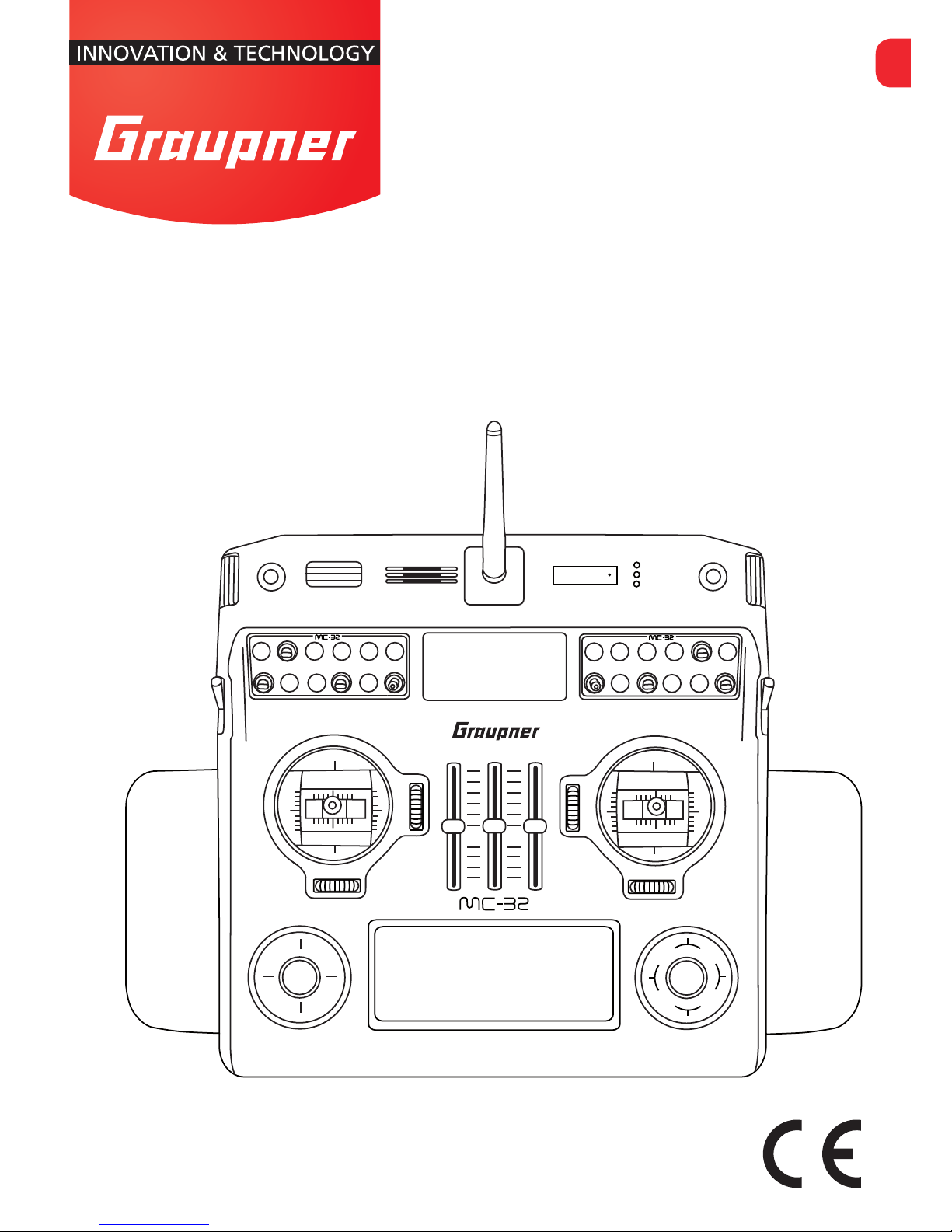
mc-32 HoTT
No. 33032
Manual
EN
1
2
3 4
7
5
6
8
1
2
3 4
7
5
6
8
Page 2

2 / 36
33032_jp_V1
Page 3

3 / 36
33032_jp_V1
Index
Introduction ..........................................................................5
Service Centre .....................................................................5
Intended use ........................................................................6
Target group ......................................................................6
Package content .................................................................6
Technical Data .....................................................................7
Symbols explication ............................................................8
Safety notes .........................................................................8
For your safety by handling the transmitter ........................9
For your safety by handling the battery ............................10
Description of the transmitter ..........................................12
Control elements on the transmitter .................................12
Transmitter interior ...........................................................13
Interfaces ........................................................................14
Face-side connections ..............................................14
DSCsocket .....................................................................15
Memory cards .................................................................16
Data recording/Data saving.......................................16
Display and touchpad ......................................................17
Telemetry symbols in the display ...............................18
Touch pad .......................................................................18
Keys left of the display ..............................................18
Keys to the left of the display ....................................18
Commissioning ..................................................................20
Opening/closing the transmitter housing ..........................20
Sticks conversion ............................................................20
Neutralization ............................................................20
Brake spring and ratchet ..........................................21
Control sticks centering force ...................................21
Brackets for transmitter belt ............................................21
Installation of switches, switch modules and knob
modules ..........................................................................22
Aligning the antenna ........................................................22
Switch on transmitter.......................................................22
Page 4

4 / 36
33032_jp_V1
Binding ............................................................................23
Charging the transmitter battery ......................................23
Charge possibilities ...................................................25
Low voltage warning .......................................................26
Battery use timer in the display ........................................26
Lithium battery.................................................................26
Use and menu functions ...................................................27
Short-Cuts ......................................................................27
Function field in the display .......................................28
Hidden mode ..................................................................28
Top / bottom LCD contrast .......................................28
Announcements .......................................................29
Language change .....................................................29
Firmware update/Changing the display language ......29
Stick calibration ........................................................30
Bluetooth initialization ...............................................31
Telemetry data display .....................................................31
Sensors ....................................................................31
Receiver .................................................................32
Firmware update ...............................................................33
Update through memory card ..........................................33
Declaration of conformity .................................................33
Update through USB port ................................................34
Problems during firmware update ....................................34
Notes on environmental protection .................................34
Care and maintenance ......................................................34
Warranty certificate ...........................................................34
Page 5
5 / 36
33032_jp_V1
Introduction
Thank you very much for purchasing the Graupner mc-32 HoTT
transmitter.
Read this manual carefully to achieve the best results with your
transmitter and first of all to safely control your models. If you
experience any trouble during operation, take the instructions to
help or ask your dealer or Graupner Service Centre.
NOTICE
This manual is composed by two parts. Part 1 is contained in the
product's package content. Part 2 can be found in its last version on
www.graupner.de by the related item page.
Due to technical changes, the information may be changed in
this manual without prior notice. Be always updated by checking periodically on our website, www.graupner.de to be always
uptodate with the products and firmwares.
This product complies with national and European legal requirements.
To maintain this condition and to ensure safe operation, you must
read and follow this user manual and all the safety notes before using
the product!
NOTICE
This manual is part of that product. It contains important information
concerning operation and handling. Keep these instructions for future
reference and give it to third person in case you gave the product.
Service Centre
Graupner Central Service
Graupner/SJ GmbH
Henriettenstrasse 96
D-73230 Kirchheim / Teck
Servicehotline
(+49) (0)7021/722-130
Monday - Thursday
9:15 am - 5:00 pm
Friday
9:15 am - 1:00 pm
Graupner USA
OPENHHBBY LLC
3245 University Ave
Suite 1520
San Diego, CA 92104
Website: www.graupnerusa.com
Phone: +1 855-572-4746
Email:service@openhobby.com
Graupner in Internet For the service centers outside Germany please refer to our web
site www.graupner.de
Page 6

6 / 36
33032_jp_V1
Intended use
This remote-control system may only be used for the purpose
specified by the manufacturer for operation of remote control
models without passengers. Any other type of use is impermissible and may damage the system and cause significant property damage and/or personal injury. No warranty or liability is
therefore offered for any improper use not covered by these provisions.
Read through this entire manual before you attempt to install or
use the transmitter.
Graupner/SJ constantly works on the development of all products; we reserve the right to change the item, its technology and
equipment.
Target group
The product is not a toy. It is not suitable for children under 14
years. The operation of the mc-32 HoTT transmitter must be performed by experienced modelers. If you do not have sufficient
knowledge about dealing with radio-controlled models, please
contact an experienced modeler or a model club.
Package content
Transmitter mc-32 HoTT
Transmitter battery
Receiver (optional)
Integrated Bluetooth module
Battery charger
USB Adapter/Interface
USB cable
Micro SD card with adapter
Hand pads
Transmitter straps
Aluminum case
Transmitter manual (Part 1)
Receiver manual (optional)
The programming manual (manual part 2) can be found in its last
version on www.graupner.de by the related item page.
Page 7
7 / 36
33032_jp_V1
Technical Data
Transmitter mc-32 HoTT
Frequency band 2,4 … 2,4835 GHz
Modulation FHSS
Transmitting power 100 mW EIRP
Control functions 16 functions of which 4 can be trimmed
Temperature range -10 … +55 °C
Antenna Can be turned and folded
Operating voltage 3,2 … 4,8 V
Power consumption approx. 500 mA
Range approx. up to 4.000 m
Dimensions approx. 252 x 252 x 60 mm
Weight approx. 1685 g with transmitter battery
Notice
The technical data of the optional receiver are available in the
manual included in the receiver package content.
Page 8
8 / 36
33032_jp_V1
Symbols explication
Always observe the information indicated by this warning sign.
Particularly those which are additionally marked with the CAU-
TION or WARNING. The signal word WARNING indicates the potential for serious injury, the signal word CAUTION indicates possibil-
ity of lighter injuries.
The signal word Note indicates potential malfunctions.
Attention indicates potential damages to objects.
Safety notes
These safety instructions are intended not only to protect the
product, but also for your own and other people’s safety. Therefore please read this section very carefully before using the product!
Do not carelessly leave the packaging material lying around,
since it might become a dangerous toy for children.
Persons, including children, with reduced physical, sensory
or mental capabilities, or lack of experience or knowledge,
or not capable to use safely the transmitter must not use the
transmitter without supervision or instruction by a responsible person.
Operation and use of radio-controlled models needs to be
learnt! If you have never operated a model of this type before,
start carefully and make yourself familiar with the model's
reactions to the remote control commands. Proceed always
responsibly.
Before you start using the remote control model, you have
to check the further relevant laws and regulations. These
laws you must obey in every case. Pay attention to the possibly different laws of the countries.
The insurance is mandatory for all kinds of model operation.
If you already have one, so please inform yourself if the operation of the respective model is covered by your insurance.
If this is not the case, conclude a special liability insurance
policy for models.
!
!
Inform yourself before flying your
model on which maximum
altitude you can fly in the uncon-
trolled airspace over the starting
position and do not exceed it.
Page 9
9 / 36
33032_jp_V1
Protect all equipment from dust, dirt, moisture. All equip-
ment must be protected from vibration as well as excessive
heat or cold. The models may only be operated remotely in
normal outside temperatures such as from -10°C to +55°C.
Always perform a range test and functional test on the ground
before you use your model! Only so you ensure safe operation! To know how to perform a range check, please read
Part 2 of the manual.
Use all HoTT components only with the current software ver-
sion.
Save by each use of your model the log file. With a log file it
is possible to trace possible occurring technical failures. Only
so any claims can be considered.
For your safety by handling the transmitter
WARNING
Also while programming the transmitter, make sure that a connected motor cannot accidentally start. Disconnect the fuel supply or drive battery beforehand.
CAUTION
Risk of fire! Avoid every kind of short-circuit in all sockets of the
transmitter! Use only the suitable connectors. In no case the
electronic component of the transmitter may be changed or
modified. Due to licensing reasons, any reconstruction and/or
modification of the product is prohibited.
Note
During transport protect the model and the transmitter from
damages.
!
!
Page 10

10 / 36
33032_jp_V1
For your safety by handling the battery
CAUTION
Protect all equipment from dust, dirt, moisture. Only use in
dry locations.
Do not use any damaged battery. Risk of injury!
Any alterations to the battery can cause serious injury. Risk
of fire!
Batteries may not be heated, burned, short-circuited or
charged with excessive current or with reversed polarity.
While they are being charged, the batteries must be placed
on a non-flammable, heat-resistant and non-conductive surface. Combustible or highly flammable objects are to be kept
away from the charging area. Batteries must be monitored
while they are being charged.
The maximum quick charging current specified for the
respective cell type may not be exceeded.
If the battery heats up above 60°C while it is being charged,
stop charging and let the battery cool down to approximately
30 - 40°C.
Never charge batteries that have already been charged, are
hot or are not fully discharged. If a cell in a battery pack has
become particularly hot following a quick-charge process,
this may indicate a defect in that cell. Do not use the battery
pack any more!
The batteries must not be modified. Do not directly solder or
weld the cells.
If handled improperly, there is a danger of fire, explosion, irri-
tation and burns. To extinguish a fire use: water, CO2, sand.
Leaked electrolyte is caustic and should not be touched or
come into contact with your eyes. In case of emergency,
rinse with a large quantity of water and consult a Med. Doctor.
!
Page 11

11 / 36
33032_jp_V1
Always charge the battery fully.
The maximum charging current permitted may not be
exceeded.
Never leave the charger unattended when it is connected to
the power supply.
Batteries may only be charged in rooms fitted with smoke
detector.
Special instructions
To charge and discharge batteries, only use specifically
designed chargers/dischargers with balancer connector.
The white connector (cell count + 1 pole) is designed for the
connection to a LiPo balancer or a battery charger as a single cell charger with a manual cell balancer. Always charge
the battery with the balancer connector.
Safety notes for stocking batteries
Batteries may only be stored in non completely discharged
condition.
The cell voltage should not fall below 1.2 V when stored for
a long time.
Batteries may only be stored in dry rooms with an ambient
temperature of +5°C to +25°C.
Stock the LiPo batteries with a cell voltage of about 3,8V. If
the cell voltage falls below 3 V, then the battery must be necessarily charged. Deep discharge and storage in discharge
status (cell voltage < 3V) make the battery useless.
Charge and transport your batteries always in a safety bag.
Page 12

12 / 36
33032_jp_V1
Description of the transmitter
Control elements on the transmitter
1 Knob control (depressible): left "DG4", right "DG2"
2 Connection sockets (protected by a cover)
3 Control sticks (2 sticks for a total of four independent control functions)
4 Roller control
5 Speaker
6 Antenna with folding and swivel joint
7 LCD (telemetry indicators, standard receiver parameters)
8 ON/OFF switch and LED indicators (battery, RF radiation, warning signals)
9 Option locations (for retrofitting the transmitter with switches and knob modules 8 switches included as
standard equipment)
10 Rotary controls (left "SD2", right "SD1")
11 Touch pad
12 Digital trim
13 3 slider controls "SR1", "SR2". "SR3“
14 LCD
1
2
3 4
7
5
6
8
1
2
3 4
7
5
6
8
6
1
2
8
10
9
10
4
11
14
13
9
251
4
7
12
3
3
12
12
12
11
4
Page 13

13 / 36
33032_jp_V1
Transmitter interior
1 3 free plug-in locations and blind connectors (for 3 proportional rotary control modules) for optional
controls and switches (connection sequence as preferred)
2 INT PPM plug-in location (one free plug-in location for connecting an additional – internal – RF module)
3 Transmitter battery
4 Transmitter battery plug
5 Plug-in locations (6 free plug-in locations for additional switches are standard, these switch plug-in
locations can be used in any sequence)
6 Plug-in locations (UVR, 5-pole 2 x 4 free plug-in locations for future rotary control installations)
7 Lithium battery CR2032 (not rechargeable but changeable)
1
2
5
76
1
3
4
Page 14

14 / 36
33032_jp_V1
Interfaces
Face-side connections
Left face-side connections
1- Card slot
The card slot is suitable for micro SD memory card. For information on removing and inserting the memory card, refer to the
section "memory cards".
2- Ear phones port
The ear phones port is suitable for a 3,5 mm jack. Though this
interface both acoustic signals and voice messages are emitted.
The volume can be controlled by "Voice volume" and "Signal volume" in the general settings.
3- EXT.PPM
Here it is possible to connect an external RF module.
4- SPI
To the SPI marked port is possible to connect an interface for
future use. The port is actually not implemented and should not
be used-
Right face-side connections
1- Charging socket
Through the charging socket you can charge the transmitter
battery using the supplied plug-in charger.
DO NOT USE PLUG-IN CHARGERS BY OTHER MANUFACTURERS OR
OTHER CHARGERS.
The maximum charge current is 1,5 A.
More information are available in the section "Charging the transmitter battery".
2- DSC socket
In the middle of the right provided connections is located the
DSC socket. This socket allows the trainer/pupil function or for
flight simulators.
For more information on the DSC socket and the trainer/pupil
function see the section "DSC socket".
3- Mini-USB connection
Note
The mini USB socket is not suitable for flight simulator connection.
Through this socket it is possible to connect the transmitter to
a PC. The software that the computer needs as well as the
3
1
2
4
1
2
4
3
Page 15

15 / 36
33032_jp_V1
appropriate USB driver can be found on the download page on
www.graupner.de for the respective product.
4- Data socket
The data socket is suitable for connection of an optional smart
box or an external optional Bluetooth module.
DSCsocket
Connection socket for flight simulator or T/P systems
The standard two-pin DSC socket on the transmitter functions
as a TRAINER or PUPIL socket as well as an interface for flight
simulators or other external RF modules.
To ensure a correct DSC connection, observe the following:
1. Perform any necessary adaptations in the menu.
2. When using the transmitter with a flight simulator or during
the teacher-pupil operation, set the On/Off switch always on
the "Off" position. Only in this position even after connecting the
DSC cable the RF module of the transmitter remains inactive.
The status LED is constantly red and in the display will appear
DSC.
In the mc-32 HoTT transmitter upper display appears the transmitter logo.
The transmitter is now ready for use.
Note
If the transmitter is used as teacher transmitter it has to be switched
on before connecting the proper cable.
3. Connect the other end of the connecting cable to the device
while observing the relevant operating instructions.
Note
Make sure that all the plugs are securely inserted in the respective
sockets, and only use the provided plug-in connectionswith a 2-pin
jack plug on the DSC side.
4. In the "Transmitter setting" submenu, you can set one of the
following modes in the "DSC output" line depending on the
number of functions to be transmitted: PPM10, PPM16, PPM18
and PPM24. Default setting: PPM10.
Page 16

16 / 36
33032_jp_V1
ATTENTION!
When your transmitter is directly connected to a desktop computer
by a connecting cable (DSC cable) and/or a computer interface is
connected to your simulator, the transmitter may be destroyed
byelectrostatic discharge. This type of connection should therefore
only be used if you protect yourself from electrostatic discharge
while operating the simulator by wearing a commercially available
grounding armband. Graupner therefore strongly recommends only
using wireless simulators.
Memory cards
Micro SD cards up to 2 GB and micro SDHC up to 32 GB are
compatible memory cards.
Our recommendation: For a normal use a memory card with a
storage capacity of up to 4 GB is sufficient.
Inserting and removing the memory card step by step:
Switch off the transmitter.
The memory card slot is located in the left provided connections
of the transmitter.
To insert:
Push the SD card as deep as you need to win the spring resistance of the slot.
To remove:
Push the SD card slightly toward the card slot to unlock it and
then remove it.
The included memory card is ready for use as soon as the transmitter is switched on. In the display appears the symbol of a
memory card.
Otherwise, folders are created on the memory card ( represented in the transmitter display by a permanent filling from left
to right memory card). When the animation finishes, the inserted
memory card is ready for use.
You can connect the memory card to your PC by using a memory card reader. Copy the data downloaded from the transmitter
page on the web site in the related folder of the memory card.
Insert the memory card in your transmitter.
Data recording/Data saving
The data recording in the SD card is linked to the flight timer. If
it is started, the data recording starts as well and it stops when
the flight timer is stopped.
The data writing on the memory card is remarked by the symbol
of the "filling" of the memory card with black from left to right.
Page 17

17 / 36
33032_jp_V1
After the installation of the memory card, there is a folder structure in it. These folders are actually empty.
Finally, the log files are saved in subfolders called "Modelname"
named according to the structure 0001_year-month-day.bin. If a
model memory is still nameless, the corresponding log files are
saved in a subfolder entitled "NoName".
In the folder "Models" are saved the exported model memories.
The data can be evaluated on a compatible computer using the
programs found on the downloads page for the transmitter
under www.graupner.de.
Display and touchpad
1 Model memories 1 … 80
2 Model type display (plane/heli)
3 Model name
4 Model operating time
5 User name
6 Operating mode HoTT/PPM
7 Flight chronometer in min:s (forward/reverse)
8 Flight timer in min:s
9 Transmitter battery voltage with dynamic bar indicator (if the battery voltage underruns the 3.6 V (adjust-
able) threshold a warning message will appear and an acoustic warning will sound)
10 Graphic display of the position of the four digital trimming levers with a numeric position and direction
display.
11 Symbol "micro SD card insert"
12 Transmitter operating time (automatically reset to 00:00 if the voltage is at least 0,3 V higher)
13 Signal power
14 Operating mode
15 Graupner logo or flight phase name
16 Receiver battery voltage RX-VOLT
2 31 5 6
9 10 12 1011
4
7148
13 1615
Page 18

18 / 36
33032_jp_V1
Telemetry symbols in the display
The active model memory has not yet been bound to a receiver.
Not flashing: RF transmitter function switched off.
Blinking antenna symbol: Last receiver bound to the active
model memory is inactive or out of reach
No telemetry signal to receive
Signal strength display of the model connection
Signal strength display of the connection with pupil transmitter
in the teacher transmitter display with wireless connection
Touch pad
Keys left of the display
ESC key
Pushing the ESC button brings about a stepwise return to function selection or back to the basic display. Any setting changed
in the meantime is retained.
Momentarily touching the ESC key for about 1 second while in
the base screen will open and close the Telemetry menu.
Selection keys
Momentarily pressing one of these keys will cause analogous
paging in the given arrow direction through lists, e. g. through
the model selection list or the multi-function list or within menus
though the menu lines.
Brief simultaneous pushing the
keys will cause a jump from
the transmitter's base screen or from almost any menu position
to the "Servo display" menu,
Keys to the left of the display
SET key
1. Briefly pushing the SET key will cause a jump from the displayed base screen to the multi-function menu. By pushing the
SET key it is possible to accede to a previously selected menu.
2. In the settings menu activate (confirm) the settings fields by
pressing the SET button.
Selection keys
1. "Paging" through the multi-function menu and the menu lines
within the Basic Settings menu analogous to the arrow keys of
the left touch pad.
2. Select or set parameters in setting fields after they have been
activated by briefly touching the SET key, whereby the
keys
and
are used for the same corresponding functions.
M
M
P
Page 19

19 / 36
33032_jp_V1
3. By briefly pressing the keys simultaneously or an altered
parameter value for the active entry field will again be restored
to its default value (CLEAR).
Note
In the event the keys do not exhibit any functionality immediately
after switching the transmitter off and then on again right away, this
is not a fault. Just switch the transmitter off again then wait for sev-
eral seconds before switching it on again
Page 20

20 / 36
33032_jp_V1
Commissioning
Opening/closing the transmitter housing
The transmitter should be opened only in the following cases:
If a self centering stick has to be converted in non self cen-
tering
If a non self centering stick has to be converted in self cen-
tering
To set the control stick centering force
Open step by step
Before opening the housing switch the transmitter off.
Push both housing base latches in the opposite the direction of
the arrow marks, toward the inside, to their limits.
Now tilt the transmitter somewhat to the rear so the housing
base can flip open and can be unhooked.
!
CAUTION
Never switch the transmitter on while the housing is open! Do not
touch the electronic boards.
Closing step by step:
Hook the transmitter's housing base to the underside.
To lock the transmitter bottom case, flip the base closed then
push both latches toward the outside.
Sticks conversion
Neutralization
Both control sticks can be set from neutralizing to non-neutralizing.
Neutralizing step by step:
Locate in the left control stick gimbal the screw surrounded by
a white circle in the picture.
Turn the screw toward the inside of the transmitter until the relevant control stick can move freely from stop to stop, or turn it
outward until the control stick resets itself independently.
Note
The right control stick gimbal is specular to the left one, so that here
the screw is located right under the middle.
Page 21

21 / 36
33032_jp_V1
Brake spring and ratchet
Locate the screws indicated by a white circle in the picture.
The outboard screw of the two marked in the figure adjust the
braking force.
The inboard screw adjusts the strength of the ratchet for the
respective control stick.
Note
The right control stick gimbal is specular to the left one, so that here
the screws are located left on the top side.
Control sticks centering force
The control sticks' restoring force can also be adjusted. The
adjustment is located next to the return springs.
By turning the respective adjust screw the spring force can be
adjusted.
Right turn = return harder
Left turn = return softer
Brackets for transmitter belt
A stable transmitter hanger for fastening neck straps is standard
equipment on the mc-32 HoTT transmitter.
Installing the metal brackets:
Push both brackets inward a bit near where they are engraved.
Turn them upward by 90 °. The brackets will automatically lock
into position.
If you have a neck strap fastened to the holder bracket with keyrings, first press lightly on the right holder bracket to release its
latch. So it can be folded down. Use the same procedure for the
left bracket.
Afterward push both brackets simultaneously into the recess.
vertical
horizontal
Page 22

22 / 36
33032_jp_V1
Installation of switches, switch modules and knob modules
There are a total of 20 holes in the transmitter's housing available for mounting accessory modules.
!
WARNING
To be safe, always disconnect the transmitter battery before installation to avoid short circuit conditions.
Be sure to pay attention that soldered points on the transmitter board
do not come into contact with metal objects!
Unoccupied holes in the transmitter's housing are closed with
blind plugs. These can easily be pulled out from the outside.
Insert the accessory switch, etc. through a hole in the housing
from the inside.
Fixing the switch, switch module and knob module
The fixation is made by screwing a nut on the thread on the
upper part of the switch. These will pass though the housing and
tightened with a suitable wrench. The Graupner trim nut wrench
is well suited for tightening down these nuts.
Aligning the antenna
The removable, articulated antenna is to be screwed into the
ball-joint connector then aligned by hand.
Do not point the antenna directly to the model. Turn and bend
the antenna so that during the use it is oriented to a side (see
picture on the left) or alternatively turn it perpendicularly to the
top.
CAUTION
When screwing in the antenna, pay attention that the centre pin in
the antenna socket does not get bent or pressed back in the socket.
Switch on transmitter
Safety query
When the transmitter is switched on the throttle position is checked.
(Premise: Model type "winged" "Motor at ch1 front/back" or model
type "Heli" is selected) If the throttle stick is set out of the minimum
position, the warning message "THR too high!" appears and the RF
module remains off for safety reasons.
!
WARNING
If you do not follow the afore mentioned instructions, the connected
drive motor can run accidentally when the transmitter is switched
on. Risk of injury! Always program a switch for motor stop!
Throttle
too
high!
Page 23

23 / 36
33032_jp_V1
Otherwise the RF module will be activated when the transmitter
is switched on and in the display appears a selection indicator.
Select with the selection buttons of the right touch pad RF ON/
OFF. By tipping the SET button on "OFF" the RF module is
switched off.
The color of the lighting central LED changes to red and you are
now in the transmitter main menu display.
The symbol
mean that the currently active model memory has
once been linked to a receiver but is presently not linked. (We
have turned the RF module off for example reasons.) If instead
the transmitter was switched on without turning off the RF module, the central LED would light blue and the symbol
would
blink. Contemporaneously a warning acoustic signal is emitted
until a connection is established with the respective receiver. As
soon as this connection is established appears a a field strength
indicator
and the warning signal stops.
If the telemetry connection is established the respective indication of the receiver signals strength so as the actual
receiver power supply voltage.
On the other hand, if the screen displays the symbol combination
and the center LED illuminates in red continuously then
the currently active model memory is not "bound" to any receiver.
Binding
Explications about the binding process can be found in
the Part 2 of the manual.
For a transmitter commissioning the receiver must be bound to
the transmitter. This binding process is necessary for the operation of the model!
The exact sequence of the binding operation is described in the
section „Binding“ in the Part 2 of the manual and in the respective receiver manual. Note: The procedure will be different for the
different receiver types.
Charging the transmitter battery
WARNING
Protect the charger from dust, dirt, moisture, vibrations and
other foreign parts.
The charger should always be supervised during charge and
it should be used only in rooms fitted with a smoke detector.
The charger and the battery to be charged must be placed
on a non-combustible, heat-resistant and non-conducting
surface during operation. Do not use the charger near easily
flammable materials.
Verify if the charger is suitable for your battery type.
RF on/off?
OFF
ON
Please select
RF on/off?
ON
Please select
OFF
M
!
Page 24

24 / 36
33032_jp_V1
Always connect only one battery to the battery charger out-
put.
Use only batteries and battery cables with suitable connec-
tors and reverse polarity protection. Make sure that the
polarity is correct.
After the charge is complete disconnect the charger from the
power source.
Page 25

25 / 36
33032_jp_V1
The battery charger can be used only in dry spaces.
A wet charger, even if re-dried, should no longer be used.
Never use a damaged battery charger.
Due to licensing reasons, any reconstruction and/or modifi-
cation of the product is prohibited.
Be sure that during charge the charger is not covered. The
ventilation slots must be free.
Charge possibilities
CAUTION
The transmitter must be turned offwhile the entire charging process.
You have two charge possibilities:
1. By removing the battery from its case and charging it with a
charger
Removing transmitter battery
Remove the transmitter lower case.
Then remove and disconnect the battery plug by carefully pulling on the supply cable.
Charge the battery following the charger manual.
Inserting the transmitter battery
Connect the battery plug in the transmitter socket. Make sure
that the polarity is correct. Pay attention to the respective "+"
and "-" symbols near the socket.
Red = +
Black/brown = -
Place the battery into its compartment and close the cover.
2. Through charge socket and charge with AC charger
CAUTION
Do not use plug-in chargers by other manufacturers or chargers that
were designed for different battery types. Transmitter and battery
can be damaged. Risk of fire!
!
!
Page 26

26 / 36
33032_jp_V1
Make sure that the transmitter is switched off. The transmitter
must be turned offwhile the entire charging process.
Connect the jack of the included AC charger to the charge
socket.
A completely discharged battery requires approx. 15 hours to
be charged.
Polarity of the mc- charge socket
The charging cables available on the market by other manufacturers frequently have different polarities. For this reason, you
should only use original Graupner charging cable.
NOTE
The charging socket comes standard with a protection switch that
protects against polarity reversal. Original Graupner automatic chargers recognize the battery charge. In order to prevent damage to the
protection switch and to the other components, charging current
should never exceed 1 A.
Low voltage warning
The transmitter battery voltage should be monitored in the LCD
display during operation. In case the voltage drops under a preset threshold, standard setting 3,6 V, an acoustic warning signal
is emitted and in the display appears in a window "battery needs
charging".
Now at the latest, stop operation and recharge the transmitter
battery!
Battery use timer in the display
The battery use timer is shown in the lower left part of the display.
The battery use time is added at every use. After every charge
the timer is reset to "00:00". This happens only if the battery voltage increases at least of 0,3V.
Lithium battery
On the transmitter board there is a fixture for a replaceable lithium battery of type CR 2032.
This battery maintains the date and time settings during a transmitter power supply outage.
#01
0:00h
Stoppuhr
Flugzeit
K78
0:00.0
3.5V
0:00.0
00
0
0
0:00h
M
V
Akku muss
geladen
werden!!!
Page 27

27 / 36
33032_jp_V1
Use and menu functions
Short-Cuts
The following key combinations can be used to directly call up
certain menus and options:
CLEAR
Brief simultaneous touch of the
keys or on the right touch
pad will restore the active entry field's changed parameter value
back to its default value.
"Servo screen"
Brief simultaneous activation of the
keys of the left touch pad
will cause a jump from the transmitter's base screen or from
almost any menu position to the "Servo" menu,
"Telemetry" menu
Press the center ESC key in the left touch pad for about 1 s to
call up the "Telemetry" menu from the transmitter's base screen.
To come back to the base screen it is enough a "normal" touch
on the ESC key.
Graphic display of telemetry data
Briefly touching one of the arrow keys of the left or right touch
pad will cause a jump from the base screen directly to the transmitter's graphic display of telemetry data or will allow paging
back and forth between individual graphic displays.
Briefly touching the ESC or SET key will cause a return back to
the base screen.
"HIDDEN MODE"
Press and hold arrow keys
of the left touch pad then momen-
tarily touch the SET key of the right touch pad.
Entry lock
Entry lockout is activated and deactivated from the base screen
by simultaneously pressing the ESC and SET keys for about two
seconds. The entry lock is displayed by a key symbol:
The controls remain operational.
Press the ESC and SET buttons again for about two second to
release the lock.
Quick-Select
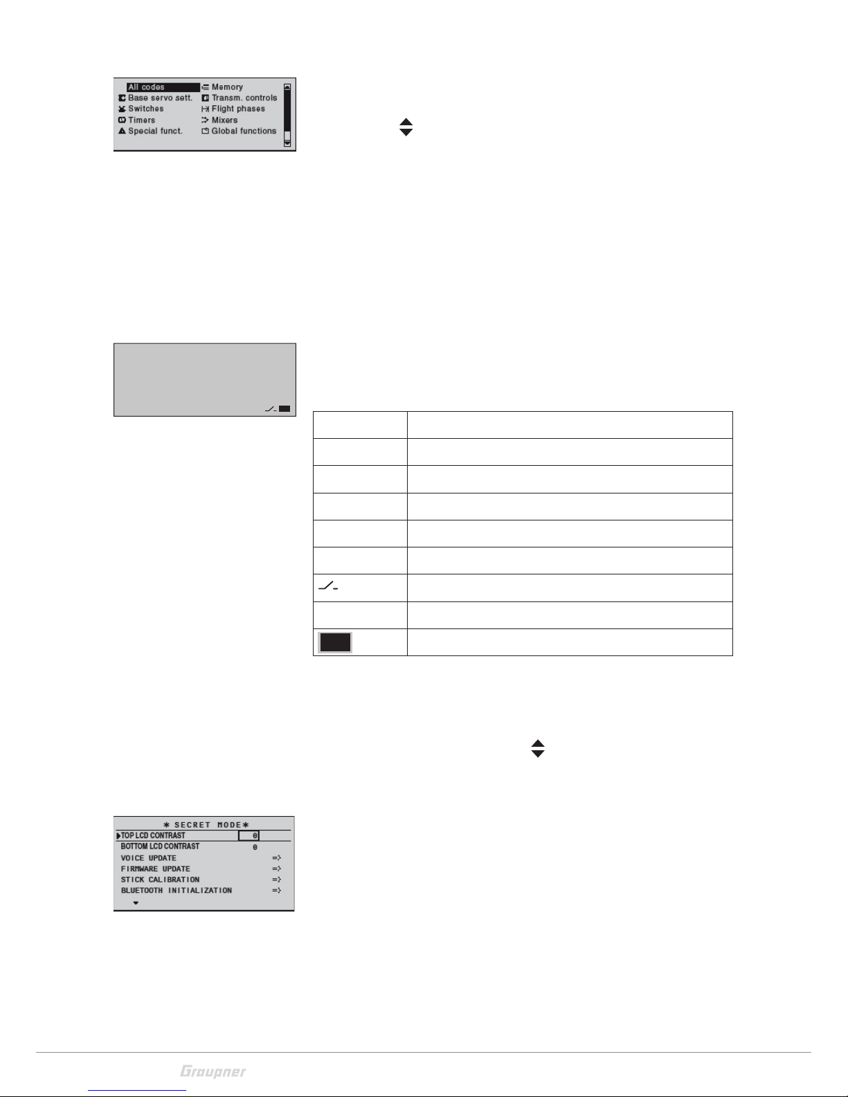
From the multi-function list, a jump can be made to a "Structure
overview" by a brief, simultaneous touch on the
or keys of
the right touch pad.
Page 28
28 / 36
33032_jp_V1
Menus are arranged in clear groups in this overview.
Select the desired menu point with the selection keys and confirm with the
key.
As soon as the key is released, only the respective generic term
for the given menu will remain listed.
Select the desired menu point with the selection keys and confirm with the SET key.
Only the menu points associated with the selected preamble are
shown.
The description of the single menu point is available in the programming manual (Manual part 2) on www.graupner.de.
Function field in the display
Depending on the given menu, certain function fields will appear
on the bottom display line.
A marked function is activated by tapping on the SET key.
CLR (CLEAR) Delete
SEL (SELECT) Selection
SET (SET) Setting
STO (STORE) Store
SYM Set values symmetrically
ASY Set values asymmetrically
Switch symbol field (assignment of all types of switches)
POS. Only in "Trim memory" menu
Within a menu, change to the next page
Hidden mode
The menu "Hidden Mode" can be reached from almost any
menu position.
Press and hold the selection key
of the left four way keys and
the SET key.
Top / bottom LCD contrast
In the "...CONTRAST" line you can adjust the contrast of each
display depending on your needs.
You can select the desired line through the selection keys and
confirm by pushing the SET key. By pushing the ESC key you
can come back to the selection line.
CLR SEL SET STO SYM ASY
Page 29

29 / 36
33032_jp_V1
Announcements
These messages are in German by default. These announcements are summarized in a voice packet which is stored in a
transmitter-internal memory but they can be replaced by a voice
packet of a different language at any time.
On the included micro SD card are already available the following languages: German, English, French, Dutch, Italian and
Spanish, Czech and Russian.
The recent language packets are available on www.graupner.de.
Language change
Language change step by step:
Insert the included memory card in its slot as described in the
"Memory card" section.
Switch the transmitter on with the RF module on.
Change in the "Hidden mode" menu.
Move to the line "ANNOUNCEMENT" by using the selection
keys.
Select the "ANNOUNCEMENT" option with the SET key.
Select the language with the selection keys.
Confirm by pressing the SET key. The selected language packet
will be stored in the transmitter memory.
The loading process is finished as soon as the progress bar at
the lower edge of the display disappears.
When this process is finished, switch the transmitter off.
Note
If the warning message "RF OFF OK", the RF module is still active.
Switch the RF module off and repeat the process.
If the data list is empty. the transmitter is not finding any valid language data in the SD card. Verify the content of the "VoiceFile" folder
in the SD card by a PC.
Firmware update/Changing the display language
Note
Before each update, check the transmitter battery charge or charge
it as a precaution, and save all model memories so that they can be
restored if necessary.
Note
Follow the "Firmware update step by step" manual steps from the
section "Firmware update" "Update per memory card".
Page 30
30 / 36
33032_jp_V1
Firmware update step by step:
Move with a short pressure on the SET key to the selection page
of the option "FIRMWARE UPDATE".
Select the firmware version with the selection keys.
Confirm by pushing the SET key.
The storing in the transmitter memory will start:
When the counter reaches the storing amount the storage process is finished and the message "Firmware upgrade success!"
appears. The transmitter reboots and it is ready for use.
Stick calibration
If the center position of your self-neutralizing control stick does
not precisely correspond to 0% control travel, you can check
and correct it as follows:
Stick calibration step by step:
Move to the "Model select" menu and initialize a free model
memory.
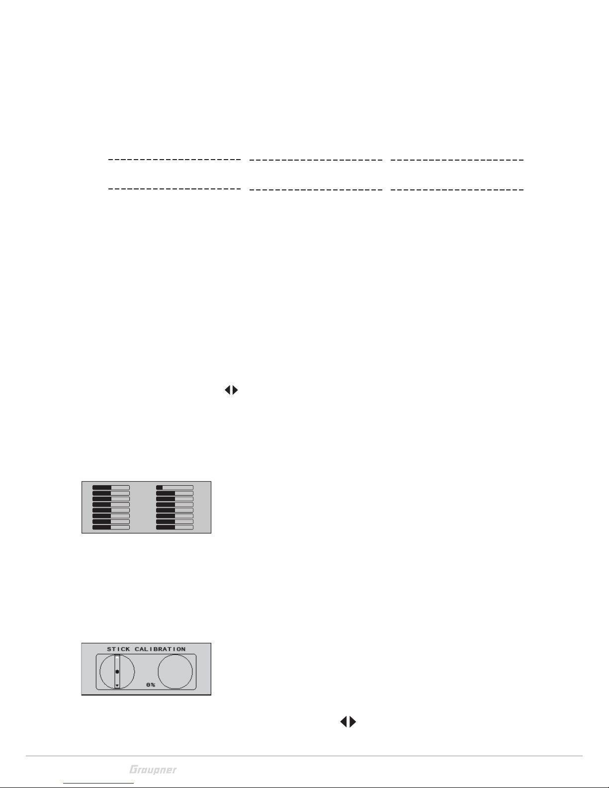
Move to the "Servo display" menu, pressing simultaneously the
keys in the left touch pad, without any interim change to trim
settings or other program settings.
In this menu point you can check if your sticks are correctly centered. Bring then all the sticks in the middle position.
One after the other, put both sticks into each of their four possible limit positions without exerting force at the limit position
and check if the value are between -100% and +100%. For
example, if control 2 is at its right limit and the other three other
control stick functions are in their respective middle positions,
then your transmitter's display should look like the one shown
on the left.
Regardless of the number of self-neutralizing control stick functions available on your transmitter, if these checks produce four
0% results and eight 100% results, then your transmitter's control sticks are optimally calibrated. You can terminate this process and then, if appropriate, delete the model memory just created.
If you note that the sticks do not reach the desired values, move
to the "Stick calibration" line in the "HIDDEN MODE" menu and
tip on the SET key.
The flashing arrows indicate in which direction you have to push
the sticks.
Confirm by pushing the SET key.
With the selection keys
of the right touch pad allow you to
Firmware Download
Process Start
Please Wait....
Boot Download
Success!!!
Please Wait....
Firmware
Downloading...
Progress 023/208
1
3
5
7
9
11
13
15
–100
0
0
0
0
0
0
0
0
0
0
0
0
0
0
0
2
4
6
8
10
12
14
16
Page 31

31 / 36
33032_jp_V1
cyclically select the positions of the four calibrated sticks.
Touching the ESC key will terminate the process and return to
the sub-menu "Stick cali.".
Example: Bring here the respective left blinking selection arrow
of the right stick to the left limit. Tip on the SET key. So the calibration of the right stick left limit. The circle in the middle of the
stylized stick blinks as confirmation.
Leave the self neutralizing stick, so that it can reach its neutral
position and push the SET key to calibrate the neutral position.
Calibration options:
The calibration options of these five proportional controls are
available ofter pushing the selection keys
or
of the right
touch pad so oft, till you arrive to the desired calibration option,
e. g. like the picture on the left.
Bluetooth initialization
In this display you can initialize an optional Bluetooth module following the manual included in the module package content.
Telemetry data display
Sensors
Any combination of to four sensors can be connected to a
receiver that operates by telemetry.
The display is used for operating the transmitter and to graphically display telemetry data. The change between these two use
mode is carried out through the selection keys
or of the
left touch pad in the main display.
So appear the telemetry display. By tipping again the selection
keys
, you can select which sensor or module you want to be
displayed.
If instead there are two "X"
in the lower part of the display
and it appears the message "CAN'T RECEIVE ANY DATA", it
means that there is no connection between receiver and transmitter and that no telemetry data is available. Turn on your
receiver, or bind a receiver to the active model memory.
Page 32

32 / 36
33032_jp_V1
Depending on the connected modules and sensors, several
selectable figures will appear. The description of these figures is
contained in the manual content in the sensor package.
The transmitter recognizes automatically the sensors. You can
view the sensors by pushing the SET key for 2 seconds or by
returning to the main menu and then to the telemetry menu. The
sensors will be listed in the display and marked with a checkmark.
Receiver
This display offers a graph of the data from the display "RX DATAVIEW“ of the "Telemetry" menu "SETTINGS, DISPLAYS".
Value Explanation
RX-S
QUA
Quality expressed as a percentage of the signal packages from
the transmitter arriving at the receiver
RX-S ST Signal strength expressed in percentage of the signal from the
transmitter arriving at the receiver
RX-dBm Level in dBm expressed as the percentage of the transmitter
signal arriving at the receiver
V PACK Shows the longest time in ms in which the data packets are
lost during a transmission from the transmitter to receiver
RX-VOLT Current operating voltage of thereceiver power supply in Volts
M-RX V Lowest operating voltage of thereceiver power supply since
the last startup in Volts
TMP The thermometer visualizes the current operating temperature
of the receiver
A detailed explication of the values on the left column is available
in the Manual Part 2 on www.graupner.de.
RX–S QUA: 100%
RX–S ST : 100%
TX–dBm: – 33dBm
RX–dBm: –33dBm
RX–VOLT:4.8V TMP
V–PACK: 10ms
CH OUTPUT TYPE:ONCE
M–RX V :4.6V +22°C
Page 33

33 / 36
33032_jp_V1
Firmware update
The programs and files which are also required for updating the
transmitter combined into one software package can be downloaded from www.graupner.de.
Download this software package from the Internet, and unpack
it on your computer. All other information can be found in internet in the same page where the software package is available.
Firmware updates of the transmitter can be performed in two
ways.
Update through memory card
Update through USB port
Note
Please note that compatible firmware is required for reliable
communication between the HoTT components. The programs
and files that are required to update are therefore combined into
a single file.
The current firmware version can be found on the Internet at
www.graupner.de.
Only operate your transmitter using the current software version.
these information can also be found at: www.graupner.de =>
Service & Support => Update and revision history for GRAUPNER
HoTT components.
Before each update, check the transmitter battery charge or
charge it as a precaution, and save all model memories so that
they can be restored if necessary.
Do not disconnect the link to the computer during an update!
Make sure that the link between the transmitter and computer is
operational.
After each update, check to make sure that the models function
correctly.
Update through memory card
Download the actual software package from the Internet, and
unpack it on your computer. Insert the supplied mini SDCard in
the card slot of your PC and copy the required firmware file from
the unpacked software package into the directory „Firmware“
on the memory card. Then, remove the memory card from the
PC and insert it in the card slot of the transmitter. Switch on the
transmitter and the RF module off.
Go to the submenu "FIRMWARE UPDATE" in the menu "Hidden
mode" and proceed as described in the "Hidden mode" section.
Declaration of conformity
33032 mc-32 HoTT
Graupner/SJ declares that the product is conform to EU norms.
EMV 2004/108/EC:
EN 301 489-1 V1.9.2
EN 301 489-17 V2.1.1
EN 62479:2010
LVD 2006/95/EC:
EN 60950-1 + A11 + A1 + A12 + A2:2013
R&TTE 1999/5/EC:
EN 300 328 V1.8.1
EN 62311:2008
Page 34

34 / 36
33032_jp_V1
Update through USB port
Download the actual software package from the Internet, and
unpack it on your computer. Connect your switched off transmitter with your PC, by using the USB cable, which is supplied
wit the package content, plug one end of the USB cable to a
free port in your computer and the other end to the transmitter.
All other information can be found in the instructions that come
in the software package.
Problems during firmware update
Problem: POWER switch without function
If a firmware update for the transmitter is unsuccessful or the
transmitter program freezes and the transmitter cannot be
turned off using the "POWER" switch, then remove the transmitter's battery after setting the switch to "POWER = OFF" position,
or pull the plug from the transmitter battery, reconnect it after
few seconds and leave the POWER switch on the "OFF" position.
In this case as well, download a current software package from
the Internet and open it on your computer or, if you have already
done this, start the program gr_Studio, and follow the information in the section "Restoration" in the instructions provided in
the software package.
Notes on environmental protection
Disposal notes
This symbol on the product, user manual or packaging indicates
that this product must not be disposed of with other household
waste at the end of its life. It must be handed over to the applicable collection point for the recycling of electrical and electronic
equipment.
The materials are recyclable as marked. By recycling, material
reusing or other forms of scrap usage you are making an important contribution to environmental protection.
Batteries and accumulators must be removed from the device
and disposed of at an appropriate collection point. Please inquire
if necessary from the local authority for the appropriate disposal
site.
Care and maintenance
Notes on care
The product does not need any maintenance. Always protect it
against dust, dirt and moisture.
Clean the product only with a dry cloth (do not use detergent!)
lightly rub.
Warranty certificate
The Graupner, Henriettenstrassee 96, 73230 Kirchheim/Teck
grants from the date of purchase of this product for a period of
24 months. The warranty applies only to the material or operational defects already existing when you purchased the item.
Damage due to misuse, wear, overloading, incorrect accessories or improper handling are excluded from the guarantee. The
legal rights and claims are not affected by this guarantee. Please
check exactly defects before a claim or send the product,
because we have to ask you to pay shipping costs if the item is
free from defects.
The present construction or user manual is for informational purposes only and may be changed without prior notice. The current version can be found on the Internet at www.graupner.de
on the relevant product page. In addition, Graupner/SJ has no
responsibility or liability for any errors or inaccuracies that may
appear in construction or operation manuals.
No liability can be accepted for printing errors.
P
Page 35

35 / 36
33032_jp_V1
Page 36

 Loading...