

Page 1
Anleitung für Verstärker
Best.-Nr. 2383
Herstellererklärung der Fa. Graupner GmbH & Co KG
Sollten sich Mängel an Material oder Verarbeitung an einem von uns in der
Bundesrepublik Deutschland vertriebenen, durch einen Verbraucher (§ 13 BGB)
erworbenen Gegenstand zeigen, übernehmen wir, die Fa. Graupner GmbH & Co
KG, Kirchheim/Teck im nachstehenden Umfang die Mängelbeseitigung für den
Gegenstand.
Rechte aus dieser Herstellererklärung kann der Verbraucher nicht geltend machen,
wenn die Beeinträchtigung der Brauchbarkeit des Gegenstandes auf natürlicher
Abnutzung, Einsatz unter Wettbewerbsbedingungen, unsachgemäßer Verwendung
(einschließlich Einbau) oder Einwirkung von außen beruht.
Diese Herstellererklärung lässt die gesetzlichen oder vertraglich eingeräumten
Mängelansprüche und -rechte des Verbrauchers aus dem Kaufvertrag gegenüber
seinem Verkäufer (Händler) unberührt.
Umfang der Garantieleistung
Im Garantiefall leisten wir nach unserer Wahl Reparatur oder Ersatz der
mangelbehafteten Ware. Weitergehende Ansprüche, insbesondere Ansprüche auf
Erstattung von Kosten im Zusammenhang mit dem Mangel (z.B. Ein-/Ausbaukosten)
und der Ersatz von Folgeschäden sind – soweit gesetzlich zugelassen –
ausgeschlossen. Ansprüche aus gesetzlichen Regelungen, insbesondere nach dem
Produkthaftungsgesetz, werden hierdurch nicht berührt.
Voraussetzung der Garantieleistung
Der Käufer hat den Garantieanspruch schriftlich unter Beifügung des Originals des
Kaufbelegs (z.B. Rechnung, Quittung, Lieferschein) und dieser Garantiekarte geltend
zu machen. Er hat zudem die defekte Ware auf seine Kosten an die folgende
Adresse einzusenden.
Fa. Graupner GmbH & CO KG, Serviceabteilung,
Henriettenstr.94 -96, D 73230 Kirchheim/Teck
Der Käufer soll dabei den Material- oder Verarbeitungsfehler oder die Symptome des
Fehlers so konkret benennen, dass eine Überprüfung unserer Garantiepflicht
möglich wird.
Der Transport des Gegenstandes vom Verbraucher zu uns als auch der
Rücktransport erfolgt auf Gefahr des Verbrauchers.
Gültigkeitsdauer
Diese Erklärung ist nur für während der Anspruchsfrist bei uns geltend gemachten
Ansprüche aus dieser Erklärung gültig. Die Anspruchsfrist beträgt 24 Monate ab
Kauf des Gerätes durch den Verbraucher bei einem Händler in der Bundesrepublik
Deutschland (Kaufdatum). Werden Mängel nach Ablauf der Anspruchsfrist angezeigt
oder die zur Geltendmachung von Mängeln nach dieser Erklärung geforderten
Nachweise oder Dokumente erst nach Ablauf der Anspruchsfrist vorgelegt, so
stehen dem Käufer keine Rechte oder Ansprüche aus dieser Erklärung zu.
GRAUPNER GmbH & Co. KG D-73230 KIRCHHEIM/TECK GERMANY
Keine Haftung für Druckfehler. Technische Änderungen vorbehalten! #0060042 03/2009
1
Page 2

Verjährung
Soweit wir einen innerhalb der Anspruchsfrist ordnungsgemäß geltend gemachten
Anspruch aus dieser Erklärung nicht anerkennen, verjähren sämtliche Ansprüche
aus dieser Erklärung in 6 Monaten vom Zeitpunkt der Geltendmachung an, jedoch
nicht vor Ende der Anspruchsfrist.
Anwendbares Recht
Auf diese Erklärung und die sich daraus ergebenden Ansprüche, Rechte und
Pflichten findet ausschließlich das materielle deutsche Recht ohne die Normen des
Internationalen Privatrechts sowie unter Ausschluss des UN-Kaufrechts Anwendung.
Wichtige Sicherheitshinweise
Sie haben einen Verstärker erworben, aus dem – zusammen mit entsprechendem
geeignetem Zubehör – ein funktionsfähiges RC-Modell fertig gestellt werden kann.
Die Einhaltung der Montage- und Betriebsanleitung im Zusammenhang mit dem
Modell sowie die Installation, der Betrieb, die Verwendung und Wartung der mit dem
Modell zusammenhängenden Komponenten können von GRAUPNER nicht
überwacht werden. Daher übernimmt GRAUPNER keinerlei Haftung für Verluste,
Schäden oder Kosten, die sich aus dem fehlerhaften Betrieb, aus fehlerhaftem
Verhalten bzw. in irgendeiner Weise mit dem Vorgenannten zusammenhängend
ergeben. Soweit vom Gesetzgeber nicht zwingend vorgeschrieben, ist die
Verpflichtung der Firma GRAUPNER zur Leistung von Schadensersatz, aus
welchem Grund auch immer ausgeschlossen (inkl. Personenschäden, Tod,
Beschädigung von Gebäuden sowie auch Schäden durch Umsatz- oder
Geschäftsverlust, durch Geschäftsunterbrechung oder andere indirekte oder direkte
Folgeschäden), die von dem Einsatz des Modells herrühren.
Die Gesamthaftung ist unter allen Umständen und in jedem Fall beschränkt auf den
Betrag, den Sie tatsächlich für dieses Modell gezahlt haben.
Die Inbetriebnahme und der Betrieb des Verstärkers erfolgt einzig und allein auf
Gefahr des Betreibers. Nur ein vorsichtiger und überlegter Umgang beim Betrieb
schützt vor Personen- und Sachschäden.
Prüfen Sie vor dem ersten Einsatz des Verstärkers, ob Ihre PrivatHaftpflichtversicherung den Betrieb von Modellschiffen dieser Art mit einschließt.
Schließen Sie gegebenenfalls eine spezielle RC-Modell-Haftpflichtversicherung ab.
Diese Sicherheitshinweise müssen unbedingt aufbewahrt werden und bei einem
Weiterverkauf des Verstärkers an den Käufer weitergegeben werden.
Folgende Punkte müssen unbedingt beachtet werden:
Der Verstärker ist nicht für Kinder unter 14 Jahren geeignet.
Kontrollieren Sie, bevor Sie das Modell fahren lassen, dieses auf eine sichere
Funktion der Fernsteuerung sowie die Steckverbindungen auf sichere und feste
Verbindung.
Prüfen Sie, ob der von Ihnen genutzte Kanal frei ist. Fahren Sie niemals, wenn Sie
sich nicht sicher sind, ob der Kanal frei ist.
GRAUPNER GmbH & Co. KG D-73230 KIRCHHEIM/TECK GERMANY
Keine Haftung für Druckfehler. Technische Änderungen vorbehalten! #0060042 03/2009
2
Page 3
Beachten Sie, dass Funkgeräte oder Sendeanlagen die Funktion des Modells stark
stören können. Achten Sie möglichst darauf, dass keines dieser Geräte in der Nähe
betrieben wird während Sie das Modell betreiben.
Die empfohlene Betriebsspannung nicht übersteigen. Eine höhere Spannung kann
zum Zerstören des Verstärkers führen.
Setzen Sie den Verstärker nicht starker Luftfeuchtigkeit, Hitze, Kälte sowie Schmutz
aus.
Achten Sie besonders auf die Wasserdichtheit des Modells. Lassen Sie das Modell
nach Gebrauch gut austrocknen.
Pflege und Wartung
Entfernen Sie evtl. eingedrungenes Wasser durch Öffnen der Abdeckung. Sollte
Wasser in den Verstärker gedrungen sein, legen Sie diesen trocken und schicken
Sie ihn zur Kontrolle an die zuständige GRAUPNER Servicestelle ein.
Eine wirksame Vorbeugung gegen Feuchtigkeit ist, das Modul mit WET.PROTECT
Best.-Nr. 968.50 einzusprühen.
Funktion
Der NF-Verstärker wurde speziell für unser Soundswitch 1 entwickelt. Mit diesem
Verstärker kann eine deutlich höhere Lautstärke erzielt werden, als mit der, im
Soundswitch 1 verbauten Endstufe.
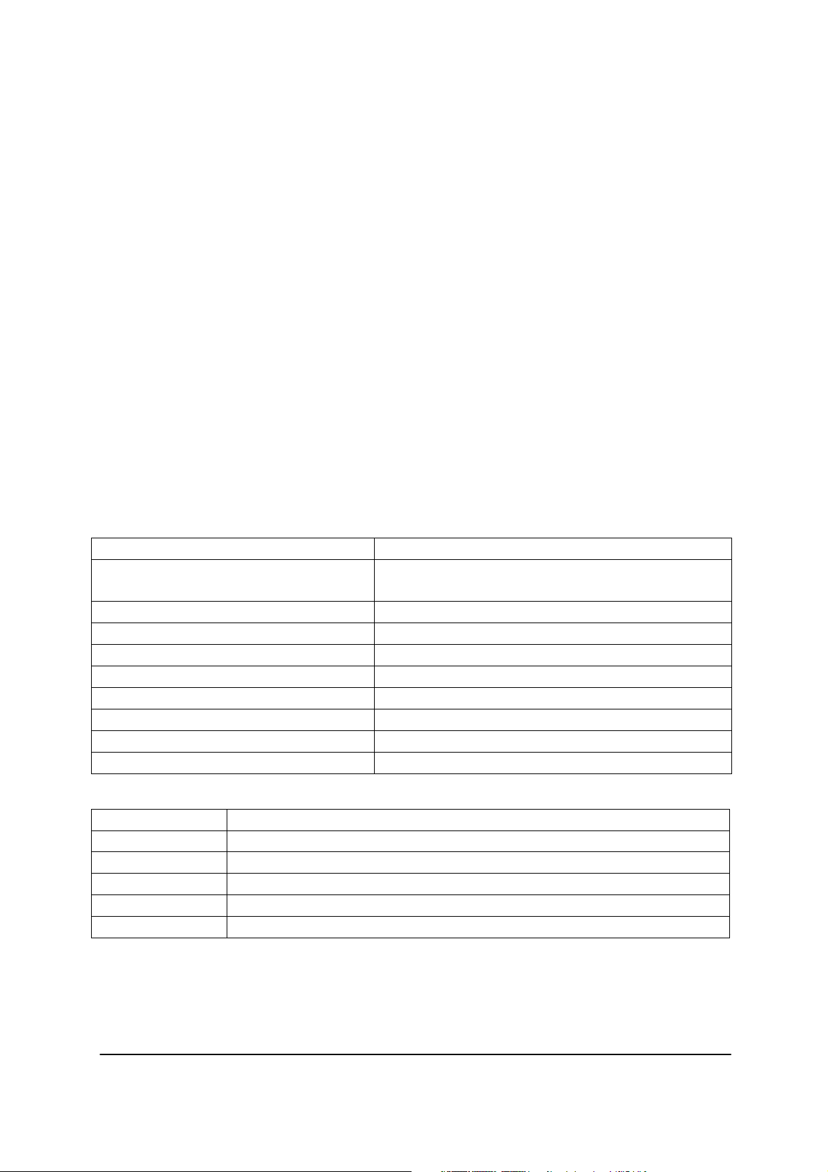
Technische Daten
Versorgungsspannung: 6 - 15V Gleichspannung
Stromaufnahme: Ruhestrom: ca. 60mA
Bei max. Leistung: ca. 2,5A
Max. Sinus-Leistung: 20W
Max. Musik-Leistung: mind. 50W
Max. Eingangsempfindlichkeit: ca. 2,5V
eff
/ 7V
ss
1)
Eingangswiderstand: ca. 70k Ohm
Geeignete Lautsprecherimpedanz: 2-8 Ohm
Interner Übertemperaturschutz: Abschaltung bei 140°C
Abmessung: 65 x 45 x 27 mm
Gewicht: 60g
Klemmenbelegung
NF ~ NF-Eingangssignal (von Soundmodul)
NF - Masse für NF-Eingang (von Soundmodul)
Akku + Spannungsversorgung +
Akku - Spannungsversorgung LS + Lautsprecheranschluss +
LS - Lautsprecheranschluss Beim Anschluss des Verstärkers, sollten immer recht kurze Leitungen verlegt werden
um Störeinflüsse (Brummen) zu vermeiden. Auch sollte der Verstärker räumlich
möglichst weit weg von Fahrtreglern und Motoren verbaut werden.
GRAUPNER GmbH & Co. KG D-73230 KIRCHHEIM/TECK GERMANY
Keine Haftung für Druckfehler. Technische Änderungen vorbehalten! #0060042 03/2009
3
Page 4
-
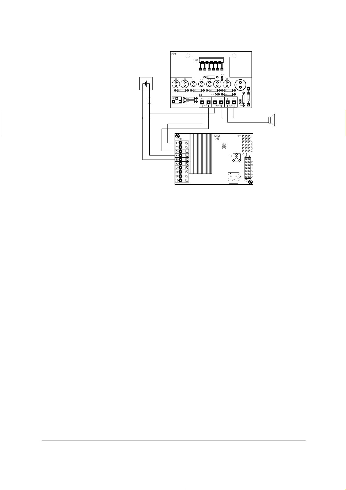
Anschlussplan
Spannungsversorgung
6 - 14V DC
+
6,3A
-
2-8 Ohm
+
Soundswitch
Lautsprecher
Es können Lautsprecher mit einer Impedanz von 2-8 Ohm angeschlossen werden.
(siehe Tabelle bei Ausgangsleistung“).
Je kleiner die Lautsprecherimpedanz ist, desto größer wird die Leistung und somit
die Lautstärke werden.
Ausnahme: Bei einer Versorgungsspannung von 12V dürfen keine Lautsprecher mit
2 Ohm angeschlossen werden, da hier die Ausgangsleistung mit knapp 30W, für den
Endstufen-IC zu hoch wäre. Sie können auch mehrere Lautsprecher parallel an den
Verstärker anschließen, um eine höhere Lautstärke zu erzielen. Zwei Lautsprecher
mit 8 Ohm, parallel angeschlossen, ergeben z.B. eine Gesamtimpedanz von 4 Ohm.
Allerdings muss hierbei darauf geachtet werden, dass die Gesamtimpedanz von 2
Ohm nicht unterschritten wird!
Die Leistung des Lautsprechers muss immer für die Ausgangsleistung des
Verstärkers ausgelegt sein!
Lautstärkeeinstellung
Auf dem Verstärker befindet sich ein Trimmer (P1) für die Lautstärkeeinstellung
Gleichzeitig ist mit diesem Trimmer auch eine Anpassung an das Soundswitch 1,
bzw. an die Höhe der Versorgungsspannung möglich.
Einstellung des Trimmers: Man dreht die Lautstärke maximal soweit auf, bis sich
die Soundwiedergabe deutlich verschlechtert. Dann ist man in dem Bereich, in dem
der Verstärker übersteuert wird.
Ausgangsleistung
Der Verstärker ist für eine maximale Ausgangsleistung von 20W ausgelegt. Dabei
handelt es sich um die reine Sinusleistung.
Die maximale Ausgangsleistung wird nur bei einer idealen Kombination von
Versorgungsspannung und Lautsprecherimpedanz erreicht.
Anhand der Tabelle ist ersichtlich, welche maximale Sinusleistung bei den
verschiedenen Spannungen und Lautsprecherimpedanzen erreicht werden kann.
GRAUPNER GmbH & Co. KG D-73230 KIRCHHEIM/TECK GERMANY
Keine Haftung für Druckfehler. Technische Änderungen vorbehalten! #0060042 03/2009
4
Page 5
U=6V U=7,2V U=8,4V U=9,6V U=12V
Leistung bei 2 Ω 5,1W 8,2W 12,0W 16,5W Leistung bei 4 Ω 2,5W 4,1W 6,0W 8,3W 13,9W
Leistung bei 8 Ω 1,3W 2,0W 3,0W 4,1W 6,9W
Leistung bei 16 Ω 0,6W 1,0W 1,5W 2,1W 3,5W
Bei kleinen Spannungen kann die maximale Ausgangsleistung nicht erreicht werden.
Ebenfalls nicht, bei zu hochohmigen Lautsprechern.
Bei dem Verstärker entsteht durch Verlustleistung eine gewisse Wärme, die über
einen Kühlkörper an die Umgebungsluft angeführt werden muss. Der Kühlkörper
wurde so dimensioniert, dass eine Sinusdauerleistung von etwa 8-10W dauerhaft
abgegeben werden kann. Für höhere Dauerleistungen wäre ein größerer Kühlkörper
notwendig, den wir aus Platz- und Gewichtsgründen allerdings nicht standardmäßig
vorsehen wollten. Sollte der Kühlkörper bei Ihnen zu heiß (>60°C) werden, kann an
den Kühlkörper noch ein weiterer Kühlkörper oder eine Metallplatte montiert werden.
Generell sollte immer auf eine möglichst gute Wärmeabfuhr (Luftzirkulation) geachtet
werden.
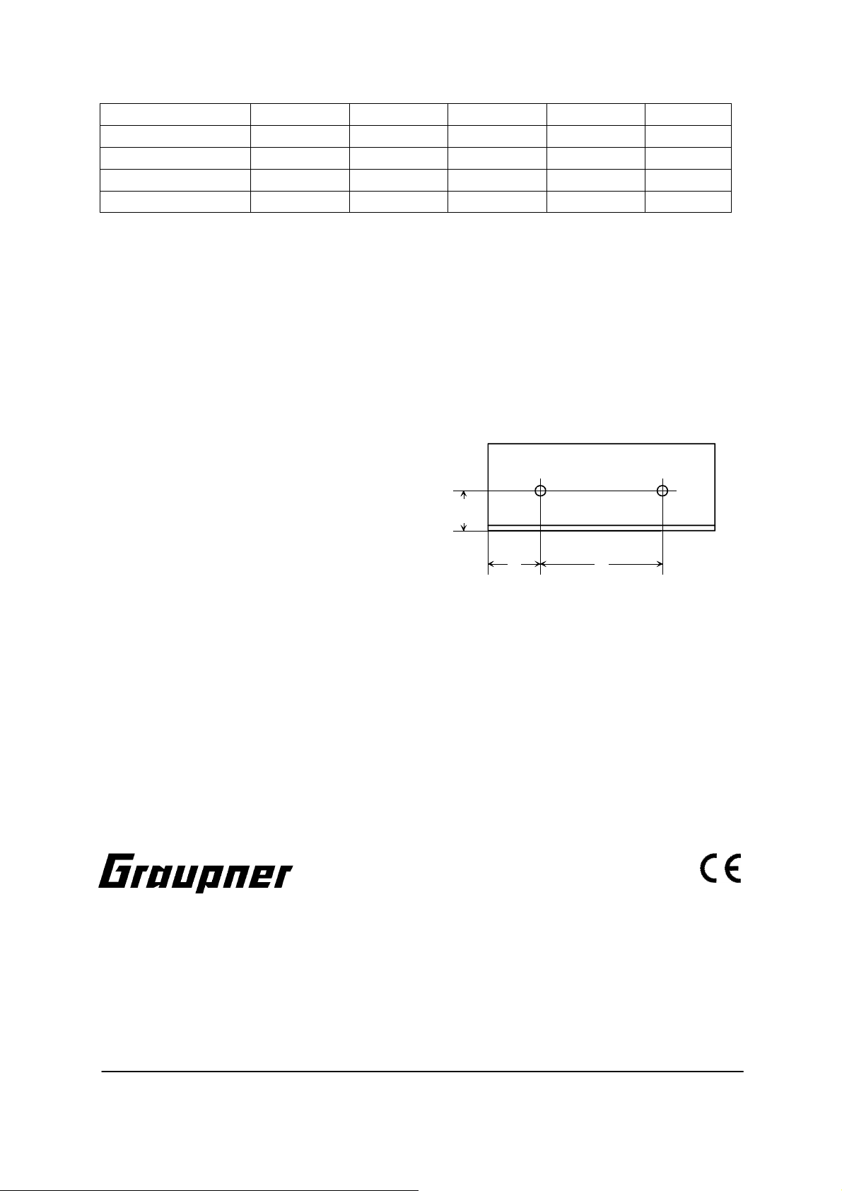
Befestigungsmöglichkeit
An dem Kühlkörper sind zwei M3-Gewinde
vorhanden, mit denen der Verstärker
irgendwo befestigt werden kann. Falls es
11,5
notwendig ist, kann hier auch noch ein
zusätzlicher Kühlkörper montiert werden.
15 35
Achtung: Der Kühlkörper liegt auf Minus-Potential! Es dürfen also keine blanken,
spannungsführenden Leitungen oder Bauteile den Kühlkörper berühren.
Viel Spaß beim Einsatz unserer Soundkomponenten in Ihrem Modell
wünscht Ihnen das
Graupner Team
Instructions for the amplifier
Order No. 2383
Manufacturer’s declaration from Graupner GmbH & Co. KG
If material defects or manufacturing faults should arise in a product distributed by us
in the Federal Republic of Germany and purchased by a consumer (§ 13 BGB), we,
GRAUPNER GmbH & Co. KG D-73230 KIRCHHEIM/TECK GERMANY
Keine Haftung für Druckfehler. Technische Änderungen vorbehalten! #0060042 03/2009
5
Page 6

Graupner GmbH & Co. KG, D-73230 Kirchheim/Teck, Germany, acknowledge the
obligation to correct those defects within the limitations described below.
The consumer is not entitled to exploit this manufacturer’s declaration if the failure in
the usability of the product is due to natural wear, use under competition conditions,
incompetent or improper use (including incorrect installation) or external influences.
This manufacturer’s declaration does not affect the consumer’s legal or contractual
rights regarding defects arising from the purchase contract between the consumer
and the vendor (dealer).
Extent of the guarantee
If a claim is made under guarantee, we undertake at our discretion to repair or
replace the defective goods. We will not consider supplementary claims, especially
for reimbursement of costs relating to the defect (e.g. installation / removal costs)
and compensation for consequent damages unless they are allowed by statute. This
does not affect claims based on legal regulations, especially according to product
liability law.
Guarantee requirements
The purchaser is required to make the guarantee claim in writing, and must enclose
original proof of purchase (e.g. invoice, receipt, delivery note) and this guarantee
card. He must send the defective goods to us at his own cost, using the following
address:
Graupner GmbH & Co. KG, Service Department,
Henriettenstr. 94 - 96, D-73230 Kirchheim / Teck, Germany
The purchaser should state the material defect or manufacturing fault, or the
symptoms of the fault, in as accurate a manner as possible, so that we can check if
our guarantee obligation is applicable.
The goods are transported from the consumer to us and from us to the consumer at
the risk of the consumer.
Duration of validity
This declaration only applies to claims made to us during the claim period as stated
in this declaration. The claim period is 24 months from the date of purchase of the
product by the consumer from a dealer in the Federal Republic of Germany (date of
purchase). If a defect arises after the end of the claim period, or if the evidence or
documents required according to this declaration in order to make the claim valid are
not presented until after this period, then the consumer forfeits any rights or claims
from this declaration.
Limitation by lapse of time
If we do not acknowledge the validity of a claim based on this declaration within the
claim period, all claims based on this declaration are barred by the statute of
limitations after six months from the time of implementation; however, this cannot
occur before the end of the claim period.
Applicable law
This declaration, and the claims, rights and obligations arising from it, are based
exclusively on the pertinent German Law, without the norms of international private
law, and excluding UN retail law.
Important safety notes
You have acquired an amplifier which can be installed to form part of a fully working
RC model in conjunction with suitable accessories. However, we as manufacturers
GRAUPNER GmbH & Co. KG D-73230 KIRCHHEIM/TECK GERMANY
No liability for printing errors. Technical modifications reserved. #0060042 03/2009
6
Page 7

have no control over the way you build and operate your RC model boat, nor how
you install, operate and maintain the associated components, and for this reason we
are obliged to deny all liability for loss, damage or costs which are incurred due to
the incompetent or incorrect use and operation of our products, or which are
connected with such operation in any way. Unless otherwise prescribed by binding
law, the obligation of the GRAUPNER company to pay compensation, regardless of
the legal argument employed, is excluded. This includes personal injury, death,
damage to buildings, damage due to loss of business or turnover, interruption of
business or other direct or indirect consequent damage whose root cause was the
operation of the model.
The total liability in all cases is limited to the amount of money which you actually
paid for this product.
This amplifier is installed and operated at the sole and express responsibility of the
operator. The only way to avoid injury to persons and damage to property is to
handle and operate the model with the greatest care and consideration at all times.
Before you switch the amplifier on for the first time please check that your private
third-party insurance covers the operation of model boats of this kind. If in doubt,
take out a special insurance policy designed to cover modelling risks.
These safety notes should be kept in a safe place. If you ever dispose of the model,
be sure to pass them on to the new owner.
The following points are important and must be observed at all times:
This model is not suitable for young persons under fourteen years of age.
Before you run the model check that the radio control system is working reliably, and
that all electrical connections are firm and secure.
Ensure that the frequency on which you intend to transmit is not already in use by
other modellers. Never run your boat if you are not certain that your channel is free.
Bear in mind that other radio equipment and transmitting stations can cause serious
interference to the model. Ensure that no equipment of this type is being used in the
vicinity while you are operating the model.
Do not be tempted to exceed the recommended operating voltage. Higher voltages
can easily ruin the amplifier.
Do not subject the product to high levels of humidity, heat, cold or dirt.
Take particular care to ensure that the boat is completely watertight. Allow the boat
to dry out thoroughly after each session.
Care and maintenance
Remove any water which gets inside the boat by opening the hatch cover. If you find
that water has got inside the amplifier, dry it out thoroughly and send it to your
nearest GRAUPNER Service Centre for checking.
We recommend spraying the unit with WET.PROTECT, Order No. 968.50, as this
provides effective protection against damp.
Function
The LF amplifier has been developed for use with our Soundswitch 1. The amplifier
is capable of a much greater volume of sound than the Soundswitch 1’s integral
output stage.
Specification
GRAUPNER GmbH & Co. KG D-73230 KIRCHHEIM/TECK GERMANY
No liability for printing errors. Technical modifications reserved. #0060042 03/2009
7
Page 8

Power supply voltage: 6 - 15 V D.C.
-
Current drain: Idle current: approx. 60 mA
At max. power: approx. 2.5 A
Max. sine-wave power: 20 W
Max. music power: Min. 50 W
Max. input sensitivity: approx. 2.5 V
eff
/ 7 V
ss
1)
Input resistance: approx. 70k Ohm
Suitable loudspeaker impedance: 2 - 8 Ohm
Internal over-temperature guard: Power-off at 140°C
Dimensions: 65 x 45 x 27 mm
Weight: 60g
Terminal pin-outs
LF ~ LF input signal (from sound module)
LF - Earth for LF input (from sound module)
Battery + Power supply +
Battery - Power supply LS + Loudspeaker terminal +
LS - Loudspeaker terminal When connecting the amplifier it is important to keep all cables as short as possible
in order to avoid interference effects (hum). The amplifier should also be installed as
far away as possible from speed controllers and electric motors.
Wiring diagram
Spannungsversorgung
6 - 14V DC
+
6,3A
-
2-8 Ohm
+
Soundswitch
Soundswitch
Loudspeaker
Loudspeakers with an impedance of 2 - 8 Ohm can be connected to the amplifier
(see table Output power table).
The lower the speaker impedance, the greater the output and the louder the volume.
GRAUPNER GmbH & Co. KG D-73230 KIRCHHEIM/TECK GERMANY
No liability for printing errors. Technical modifications reserved. #0060042 03/2009
8
Page 9

Exception: if you are using a 12 V power supply you must not connect loudspeakers
with 2 Ohm impedance, as the output power would then be just on 30 W, which
would be to high for the output stage IC. It is also possible to connect multiple
loudspeakers to the amplifier in parallel in order to increase volume. For example,
two 8 Ohm loudspeakers connected in parallel produce a total impedance of 4 Ohm.
If you do this please ensure that the total impedance does not fall below 2 Ohm.
Check that the power-handling capacity of the loudspeaker can cope with the
amplifier’s output power!
Volume adjustment
The amplifier is fitted with a trimmer (P1) which acts as volume control. At the same
time this trimmer can be used to match the amplifier to the Soundswitch 1, i.e. to the
level of the power supply voltage.
Adjusting the trimmer: turn up the volume to the maximum point at which you hear
a distinct deterioration in sound quality; at that point the amplifier is being
overloaded. Reduce the setting slightly.
Output power
The amplifier is designed for a maximum output power of 20 W. This is a pure sinewave value.
The maximum output power is only obtained with an optimum combination of power
supply voltage and loudspeaker impedance.
If you refer to the table you will see the maximum sine-wave power which can be
obtained with various voltages and loudspeaker impedances.
U = 6 V U = 7.2 V U = 8.4 V U = 9.6 V U = 12 V
Power at 2 Ω 5.1W 8.2W 12.0W 16.5W Power at 4 Ω 2.5W 4.1W 6.0W 8.3W 13.9W
Power at 8 Ω 1.3W 2.0W 3.0W 4.1W 6.9W
Power at 16 Ω 0.6W 1.0W 1.5W 2.1W 3.5W
At low voltages it is not possible to achieve maximum output power. The same
applies with loudspeakers whose impedance is excessive.
When the amplifier is operating a certain amount of heat is generated due to waste
power, and this must be dissipated into the surrounding air by means of the integral
heat-sink. The size of the heat-sink has been selected to ensure that a continuous
sine-wave output of about 8 - 10 W can be generated without problem. If you require
higher levels of continuous power a larger heat-sink would be necessary; we did not
want to fit this as standard due to size and weight considerations. If the heat-sink
becomes excessively hot (>60°C) in your application, a second heat-sink or a simple
metal plate can be attached to the standard heat-sink. As a general rule it is
important to provide for as effective a means of heat dissipation (air circulation) as
possible.
Installation methods
The heat-sink features two M3-threaded holes which can be used to install the
amplifier in any position. If necessary, a secondary heat-sink can also be attached by
this means.
GRAUPNER GmbH & Co. KG D-73230 KIRCHHEIM/TECK GERMANY
No liability for printing errors. Technical modifications reserved. #0060042 03/2009
9
Page 10

Caution: the heat-sink is at negative potential!
For this reason you must not allow any bare
current-bearing cables or components to
contact the heat-sink.
11,5
15 35
We hope you have many hours of fun using our sound system components in your
model.
Best wishes from
the Graupner Team
Instructions pour l’Amplificateur
Réf. N° 2383
Contenu de la déclaration du fabricant
Lorsqu’un article que nous distribuons dans la République Fédérale d’Allemagne
acquis par un consommateur (§ 13 BGB) présente un défaut de matière ou de
fabrication, nous la Firme Graupner GmbH & Co. KG, Kirchheim Teck, prenons en
charge la suppression du défaut de l’article dans les conditions ci après.
Le consommateur ne peut pas valider le droit de déclaration du fabricant lorsque le
défaut de l’article provient d’une usure naturelle, d’une utilisation dans des conditions
de compétition, d’une mauvaise utilisation (incluant le montage) ou d’influences
extérieures.
Cette déclaration du fabricant laisse inchangés le droit et les réclamations légales ou
contractuelles du consommateur provenant du contrat d’achat vis à vis de son
vendeur (le détaillant).
Conseils de sécurité importants
Vous avez fait l’acquisition d’un Amplificateur, avec lequel et les accessoires
correspondants, vous allez pouvoir réaliser un modèle R/C fonctionnel. Le respect
des instructions de montage et d'utilisation relatives au modèle ainsi que
l'installation, l'utilisation et l'entretien des éléments de son équipement ne peuvent
pas être surveillés par la Firme GRAUPNER. C'est pourquoi nous déclinons toute
responsabilité concernent les pertes, les dommages ou les coûts résultants d'une
mauvaise utilisation ou d'un fonctionnement défectueux. Tant qu'elle n'y a pas été
contrainte par le législateur, la responsabilité de la Firme GRAUPNER n'est
aucunement engagée pour les dédommagements (incluant les dégâts personnels,
les cas de décès, la détérioration de bâtiments ainsi que le remboursement des
GRAUPNER GmbH & Co. KG D-73230 KIRCHHEIM/TECK GERMANY
No liability for printing errors. Technical modifications reserved. #0060042 03/2009
10
Page 11

pertes commerciales dues à une interruption d'activité ou à la suite d'autres
conséquences directes ou indirectes) provenant de l'utilisation du modèle.
L'ensemble de sa responsabilité est en toutes circonstances et dans chaque cas
strictement limitée au montant que vous avez réellement payé pour ce modèle.
La mise en service et l’utilisation de cet Amplificateur se fait uniquement aux
risques et périls de son utilisateur. Seule une utilisation prudente et
responsable évitera de causer des dégâts personnels et matériels.
Avant le première utilisation de l’Amplificateur. vérifiez si votre assurance privée
couvre ce genre de risque. Contractez le cas échéant une assurance spéciale pour
les modèles radiocommandés
Ces conseils de sécurité devront être soigneusement conservés et remis à l’acheteur
en cas de revente de l’amplificateur
Les points suivants devront être impérativement observés :
Cet Amplificateur ne convient pas aux enfants en dessous de 14 ans.
Avant d’utiliser votre modèle, vérifiez le parfait fonctionnement de l’installation
R/C ainsi que le branchement sûr et ferme de tous les connecteurs.
Vérifiez si le canal de fréquence que vous utilisez est libre, ne faites pas évoluer
votre modèle tant que vous n’êtes pas sûr qu’il n’est pas déjà occupé.
Veuillez noter que des appareils radio ou d’autres émetteurs peuvent fortement
perturber le fonctionnement de votre modèle. Assurez-vous dans la mesure du
possible qu’aucun de ces appareils ne soit utilisé à proximité pendant que vous
faites évoluer votre modèle.
La tension d’alimentation conseillée ne devra pas être dépassée. Une tension
plus élevée pourra conduire à la destruction de l’Amplificateur.
Ne soumettez pas l’Amplificateur à une trop forte humidité de l’air, à une chaleur
ou à un froid excessif ainsi qu’aux salissures.
Veillez particulièrement à l’étanchéité à l’eau du modèle ; laissez le bien sécher
après chaque utilisation.
Entretien
Evacuez l’eau qui se serait éventuellement infiltrée en ouvrant le couvercle. Si de
l’eau a pénétré dans le module Soundswitch 1, laissez le bien sécher et
retournez le au S.A.V. GRAUPNER concerné pour contrôle.
Une protection efficace contre l’humidité consistera à vaporiser l’Amplificateur
avec le produit WET.PROTECT, Réf. N°968.50.
Fontion
L’Amplificateur NF a été spécialement développé pour notre module Soundswitch 1.
Avec cet Amplificateur, une sonorité beaucoup plus haute que celle produite par
l’étage final intégré dans le Soundswitch 1 sera obtenue.
Caractéristiques techniques
GRAUPNER GmbH & Co. KG D-73230 KIRCHHEIM/TECK GERMANY
Keine Haftung für Druckfehler. Technische Änderungen vorbehalten! #0060042 03/2009
11
Page 12

Tension d’alimentation 6 - 15V Tension continue
-
Consommation: Courant au repos env. 60mA
Avec une puissance max. d’env. 2,5A
Puissance sinusoïdale max.: 20W
Puissance musicale max.: moyenne 50W
Sensibilité d’entrée max.: env. 2,5V
eff
/ 7V
ss
1)
Eingangswiderstand: ca. 70k Ohm
Impédance de haut parleur
2-8 Ohms
adaptée:
Protection en température interne: Coupure avec 140°C
Dimensions 65 x 45 x 27 mm
Poids: 60g
Occupation des connexions
NF ~ Signal d’entrée NF (du module de son)
NF - Masse pour entrée NF (du module de son)
Accu + Tension d’alimentation +
Accu - Tension d’alimentation LS + Raccordement haut parleur +
LS - Raccordement haut parleur Des conducteurs les plus courts possibles devront toujours être utilisés pour le
raccordement de l’Amplificateur afin empêcher l’influence des perturbations
(Bourdonnements). L’Amplificateur devra aussi être installé le plus éloigné possible
des régulateurs de vitesse et des moteurs.
Schéma de câblage
Spannungsversorgung
6 - 14V DC
+
6,3A
-
2-8 Ohm
+
Soundswitch 1
GRAUPNER GmbH & Co. KG D-73230 KIRCHHEIM/TECK GERMANY
Keine Haftung für Druckfehler. Technische Änderungen vorbehalten! #0060042 03/2009
12
Page 13

Haut parleur
Un haut parleur avec une impédance de 2-8 Ohms pourra être connecté (voir le
tableau avec la puissance de sortie).
Plus faible sera l’impédance du haut parleur, plus forte sera la puissance et ainsi la
sonorité.
Exception : Avec une tension d’alimentation de 12 V, aucun haut parleur avec une
impédance de 2 ohms ne devra être connecté, car ici la puissance de sortie avec à
peine 30W serait trop haute pour l’étage final IC. Vous pourrez aussi relier plusieurs
haut parleurs en parallèle à l’Amplificateur pour obtenir une plus forte sonorité. Deux
haut parleurs de 8 Ohms reliés en parallèle donneront par ex. une impédance totale
de 4 Ohms. Il faudra cependant veiller ici à ce que l’impédance totale de 2 0mhs ne
soit pas sous dépassée !
La puissance du haut parleur doit toujours être adapté à la puissance de sortie de
l’Amplificateur !
Réglage de la sonorité
Un Trimmer (P1) se trouve sur l’Amplificateur pour le réglage de la sonorité. Avec ce
Trimmer une adaptation sur le Soundswitch 1 et sur la hauteur de la tension
d’alimentation est en même temps possible
Réglage du Trimmer : On tourne la sonorité au maximum jusqu’à ce que la
restitution du son se détériore nettement. On est ensuite dans la plage dans laquelle
l’Amplificateur sera sur commandé.
Puissance de sortie
L’amplificateur est adapté pour une puissance de sortie maximale de 20W ; il s’agit
ici d’une pure puissance sinusoïdale.
La puissance de sortie maximale sera seulement obtenue avec une combinaison
idéale de la tension d’alimentation et de l’impédance du haut parleur.
Le tableau ci-dessous indique quelle puissance sinusoïdale maximale pourra être
obtenue avec différentes tensions et impédances de haut parleur :
U=6V U=7,2V U=8,4V U=9,6V U=12V
Puissance avec 2 Ω 5,1W 8,2W 12,0W 16,5W Puissance avec 4 Ω 2,5W 4,1W 6,0W 8,3W 13,9W
Puissance avec 8 Ω 1,3W 2,0W 3,0W 4,1W 6,9W
Puissance avec 16 Ω 0,6W 1,0W 1,5W 2,1W 3,5W
La puissance de sortie maximale ne pourra pas être obtenue avec de plus faibles
tensions. de même qu’avec des haut parleurs de trop fortes impédances.
Avec l’Amplificateur une certaine chaleur se dégage par une perte de puissance qui
devra être dissipée dans l’air environnant par un radiateur. Le radiateur a été
dimensionné de façon à ce qu’une puissance sinusoïdale d’à peu près 8-10W puisse
GRAUPNER GmbH & Co. KG D-73230 KIRCHHEIM/TECK GERMANY
Keine Haftung für Druckfehler. Technische Änderungen vorbehalten! #0060042 03/2009
13
Page 14

être délivrée en permanence. Pour le plus hautes puissances permanentes, un plus
gros radiateur serait nécessaire mais qui n’a cependant pas été prévu de façon
standard pour des raisons de place et de poids. Si le radiateur s’échauffe de trop
(>60°C), un autre radiateur ou une plaque métallique pourront être montés sur le
radiateur. Il faudra généralement toujours veiller à assurer une dissipation de la
chaleur la plus efficace possible (Circulation d’air).
Possibilité de fixation
Deux taraudages M3 se trouvent sur le radiateur avec lesquels l’Amplificateur pourra
être fixé d’une façon quelconque. Un radiateur supplémentaire pourra encore être
monté si nécessaire.
Attention : Le radiateur se trouve sur le potentiel Moins ! Aucun conducteur de
courant dénudé ou autre composant ne doit toucher le radiateur.
Nous vous souhaitons beaucoup de plaisir avec nos composants de son dans votre
modèle !
Votre équipe Graupner
GRAUPNER GmbH & Co. KG D-73230 KIRCHHEIM/TECK GERMANY
Keine Haftung für Druckfehler. Technische Änderungen vorbehalten! #0060042 03/2009
14
 Loading...