

Page 1

Instructions for the Multi-Light Module, V1.2
Order No. 2381
Manufacturer’s declaration from Graupner GmbH & Co. KG
If material defects or manufacturing faults should arise in a product distributed by us in the Federal
Republic of Germany and purchased by a consumer (§ 13 BGB), we, Graupner GmbH & Co. KG,
D-73230 Kirchheim/Teck, Germany, acknowledge the obligation to correct those defects within the
limitations described below.
The consumer is not entitled to exploit this manufacturer’s declaration if the failure in the usability
of the product is due to natural wear, use under competition conditions, incompetent or improper
use (including incorrect installation) or external influences.
This manufacturer’s declaration does not affect the consumer’s legal or contractual rights regarding
defects arising from the purchase contract between the consumer and the vendor (dealer).
Extent of the guarantee
If a claim is made under guarantee, we undertake at our discretion to repair or replace the
defective goods. We will not consider supplementary claims, especially for reimbursement of costs
relating to the defect (e.g. installation / removal costs) and compensation for consequent damages
unless they are allowed by statute. This does not affect claims based on legal regulations,
especially according to product liability law.
Guarantee requirements
The purchaser is required to make the guarantee claim in writing, and must enclose original proof
of purchase (e.g. invoice, receipt, delivery note) and this guarantee card. The purchaser must send
the defective goods to us at his own cost, using the following address:
Brunel Drive
GB, NEWARK, Nottinghamshire
NG242EG
Tel. (+44) 16 36 61 05 39
Fax: (+44) 16 36 60 52 55
Email: service.uk@graupner.com
The purchaser should state the material defect or manufacturing fault, or the symptoms of the fault,
in as accurate a manner as possible, so that we can check if our guarantee obligation is applicable.
The goods are transported from the consumer to us and from us to the consumer at the risk of the
consumer.
Duration of validity
This declaration only applies to claims made to us during the claim period as stated in this
declaration. The claim period is 24 months from the date of purchase of the product by the
consumer from a dealer in the Federal Republic of Germany (purchase date). If a defect arises
after the end of the claim period, or if the evidence or documents required according to this
declaration in order to make the claim valid are not presented until after this period, then the
consumer forfeits any rights or claims from this declaration.
Limitation by lapse of time
If we do not acknowledge the validity of a claim based on this declaration within the claim period,
all claims based on this declaration are barred by the statute of limitations after six months from the
time of implementation; however, this cannot occur before the end of the claim period.
1
GRAUPNER GmbH & Co. KG D-73230 KIRCHHEIM/TECK GERMANY
No liability for printing errors. Technical modifications reserved. #0061368 12/2009
1
Page 2

Confidential
This declaration, and the claims, rights and obligations arising from it, are based exclusively on the
pertinent German Law, excluding the norms of international private law, and excluding UN retail
law.
Important Safety Notes
You have acquired a Multi-Light module which can be installed as part of a fully working RC model.
However, we as manufacturers have no control over the way you build and operate your RC model
aircraft, nor how you install, operate and maintain the associated components, and for this reason
we are obliged to deny all liability for loss, damage or costs which are incurred due to the
incompetent or incorrect use and operation of our products, or which are connected with such
operation in any way. Unless otherwise prescribed by binding law, the obligation of the
GRAUPNER company to pay compensation, regardless of the legal argument employed, is
excluded. This includes personal injury, death, damage to buildings, damage due to loss of
business or turnover, interruption of business or other direct or indirect consequent damage whose
root cause was the operation of the model.
The total liability in all cases is limited to the amount of money which you actually paid for the
model.
The Multi-Light module is operated at the sole and express responsibility of the operator.
The only way to avoid injury to persons and damage to property is to handle and operate
the model with the greatest care and consideration at all times.
Before operating the Multi-Light module for the first time, please check whether your normal
household insurance policy covers the risks involved in operating RC models of this type. If you are
not sure, take out a special third party policy which specifically covers the operation of radiocontrolled models.
These safety notes must be kept in a safe place. If you ever dispose of the model, be sure to pass
them on to the new owner.
The following points are important, and must be observed at all times:
• The Multi-Light module is not suitable for young persons under fourteen years of age.
• Before you operate your model, check that the radio control system is working reliably, and
that all plug-in connections are firmly seated.
• Ensure that the frequency you intend to use is not already in use by other modellers. Never
operate your model if you are not certain that your channel is free.
• Please remember that other radio equipment and transmitting stations can cause serious
interference to your model. Wherever possible, ensure that no apparatus of this type is
operating in the vicinity when you are running your model.
• Do not exceed the recommended operating voltage. Higher voltages may ruin the Multi-Light
module.
• Do not subject the Multi-Light module to high levels of humidity, heat, cold or dirt.
• Take particular care to waterproof your model. Open the model and allow it to dry out naturally
after every session.
Care and maintenance
• If water should get inside the model, open the access hatch and remove it immediately. If
water penetrates the case of the Multi-Light module, dry it out thoroughly before sending it to
your nearest GRAUPNER Service Centre for checking.
• We recommend that you apply WET.PROTECT, Order No. 968.50, to the module, as this
provides effective protection from damp.
2
GRAUPNER GmbH & Co. KG D-73230 KIRCHHEIM/TECK GERMANY
No liability for printing errors. Technical modifications reserved. #0061368 12/2009
2
Page 3

Operating Instructions
Introduction
The Multi-Light module has been specially developed for RC modelling applications, and provides
a means of fitting out various types of model with a wide variety of lighting signals, such as
navigation lights, flashers, panoramic lamps and searchlights, as realistically as possible.
All the lighting functions are permanently installed in the module, and cannot be altered.
The functions are selected by moving the corresponding DIP switches and connecting the lamps to
the appropriate terminals.
We have carried out thorough research on the different lighting signals for vehicles, boats and
aircraft, and the signals are programmed in a logical arrangement in the module.
This Multi-Light module can be used for a very wide variety of model types.
Safety Notes
• Please read right through these operating instructions before using the module for the first
time, and store them in a safe place for possible future reference.
• The integrated circuits employed in the Multi-Light module are delicate, and vulnerable to
damage from electro-static charge. For this reason please avoid touching these components
unless you have first “discharged” yourself, e.g. by grasping a central-heating radiator or other
earthed device.
• The Multi-Light module may only be operated on the stated power supply voltages.
• All wiring and connections should only be carried out with the circuit disconnected from the
power source.
• The Multi-Light module is not suitable for use by young persons under fourteen years of age.
Modes of operation
There are three different modes of operation:
• Boat
• Ground vehicle
• Model aircraft
The mode of operation is selected by determining the model type using the DIP switches S1.1 S1.3.
“Boat” mode
In this mode of operation the lights are controlled using a Nautic switch module fitted to the
transmitter. The Nautic signal is connected to the Prop #1 input (X4/1). The red LED on the module
flashes to indicate that the Light module is picking up the Nautic signal correctly.
For model boats with a Voith-Schneider power system, the direction of travel can be detected via
the Prop #2 (X4/2) and Prop #3 (X4/3) inputs; in this case the lighting system is automatically
switched over when the boat is towing or assisting.
If a servo is switched on (Prop #5 and #6 output), this automatically moves to and fro between the
right and left end-points.
The frequency of the flickering light can be altered by adjusting the trimmer P1.
The speed of the servos can be altered by adjusting the trimmer P2.
“Vehicle” mode
In this mode of operation the lights are controlled using a Nautic switch module fitted to the
transmitter. The Nautic signal is connected to the Prop #1 (X4/1) input. The red LED on the module
flashes to indicate that the Light module is picking up the Nautic signal correctly.
:
:
:
3
GRAUPNER GmbH & Co. KG D-73230 KIRCHHEIM/TECK GERMANY
No liability for printing errors. Technical modifications reserved. #0061368 12/2009
3
Page 4

The brake light and reversing light are switched via the Prop #2 (X4/2) input. This input is looped
between the receiver and the speed controller.
As an option, the steering channel can be looped through input #3 (X4/3). In this case the flashers
(direction indicators) are automatically switched off when the steering returns to centre after the
vehicle has completed a turning manoeuvre. If the steering channel is not connected, the flashers
continue to operate until they are switched off again using the Nautic switches.
The two servos (Prop #5 and #6 output) can be moved to right and left using the corresponding
switches on the Nautic switch module.
The frequency of the warning flasher can be altered by adjusting the trimmer P1.
The speed of the servos can be altered by adjusting the trimmer P2.
“Aircraft” mode
:
In this mode of operation the lights are controlled using a proportional channel (e.g. a slider) at the
transmitter. The proportional signal is connected to the Prop #2 (X4/2) input.
In this mode of operation the Light module’s power supply can be drawn directly from the servo
lead / receiver, i.e. it is not essential to connect a separate power supply to terminal X1. However,
in this case you must bear in mind that all the current drawn by the switched outputs flows through
the receiver. This means that the current drain of all the connected loads must not exceed 1.5 A. If
a higher current is required, you must connect a separate power supply to terminal X1.
Two servos can be connected to the Prop #5 and #6 outputs.
The servo at Prop #5 automatically runs to and fro between the right and left end-points
(searchlight).
The servo at Prop #6 can be used for a landing light. When the servo is activated, the servo runs to
the left end-point; otherwise it remains at the right end-point.
The frequency of the four-channel panoramic light and the running light (UFO only) can be altered
by adjusting the trimmer P1.
The speed of the servos can be altered by adjusting the trimmer P2.
Switched outputs
:
It is possible to connect LEDs, filament bulbs or similar to the sixteen switched outputs. The
voltage at the outputs is always the same as that of the power supply. It is therefore essential to
include dropping resistors in the LED / bulb circuits.
The value required for the resistors varies according to three different factors:
• The power supply voltage (U
• The voltage of the LED or filament bulb (U
)
B
)
L
• The current drawn by the LED or filament bulb (I)
The value of the resistor can then be calculated using the following formula:
U
- U
B
L
R = --------- I
Example
:
The power supply voltage is 7.2 V, and you wish to connect a white 3.5 V LED which draws a
current of 20 mA (= 0.020 A).
7.2 V
- 3.5 V
R = -------------- = 185 Ohm
0.020 A
However, since a resistor with a value of 185 Ohm does not exist, we take the nearest available
value, in this case 180 Ohm.
Finally the power rating of the resistor also needs to be calculated:
P = (U
P = (7.2 V
In this case a standard resistor with a power rating of 0.250 W (
- UL) x I
B
- 3.5 V) x 0.020 A = 0.074 W
1
/4 W) is adequate.
A separate dropping resistor should be used for each LED or filament bulb.
4
GRAUPNER GmbH & Co. KG D-73230 KIRCHHEIM/TECK GERMANY
4
No liability for printing errors. Technical modifications reserved. #0061368 12/2009
Page 5
Specification:
Power supply voltage (U
): 4.8 – 14 V D.C. voltage
b
Current drain: Idle current: approx. 25 mA
Switched outputs: Sixteen outputs, negative-switching, output
voltage as power supply voltage.
Continuous current: 0.8 A, brief max.: 1.2 A
Max. total current of all outputs: 6 A
Max. total current for power supply via X4/2: 1.5 A
Proportional inputs: Three (Prop #1 - Prop #3)
Servo outputs: Two (Prop #4 - Prop #5)
Suitable Nautic switch module (only
necessary for the “Boat” and “Vehicle”
• Graupner Nautic-Expert module (No. 4108)
• Robbe Multi-Switch 16 module (No. 8084)
modes of operation):
Ambient temperature range: 0 – 60°C
Relative humidity range: Max. 85%
Dimensions: 66 x 59 x 17 mm
Weight: 35 g
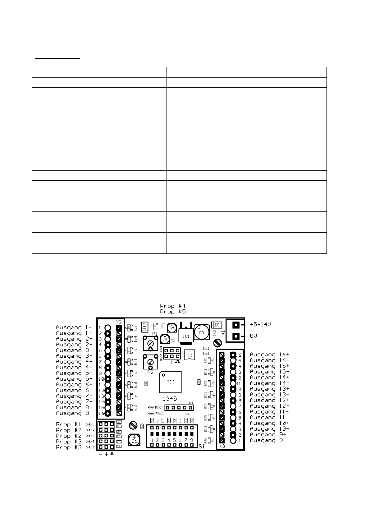
Wiring diagram
:
Output 1-8 Output 9-16
5
GRAUPNER GmbH & Co. KG D-73230 KIRCHHEIM/TECK GERMANY
5
No liability for printing errors. Technical modifications reserved. #0061368 12/2009
Page 6
A
r
Switch assignment, Graupner 4108
Fishing boat:
Output 10
7
Output 11
Searchlight
1
1
Searchlight
2
2
Servo 1
Servo 2
Power-driven vessel
Output 10
Flickering
light
Output 9
Output 12
8
Output 13
Running
3
4
At anchor
Trawling
5
Grounded
6
Not under
command
Output 12
6
Output 11
7
Output 13
8
restricted in the
Searchlight
1
1
Servo 1
Searchlight
2
2
Servo 2
Flickering
light
Output 9
Running
Draught
impeded
3
t ancho
4
5
Grounded
ability to
6
Not under
command
GRAUPNER GmbH & Co. KG D-73230 KIRCHHEIM/TECK GERMANY
6
No liability for printing errors. Technical modifications reserved. #0061368 12/2009
Page 7
A
r
A
A
r
Tug:
Searchlight
Tug with Voith-Schneider power unit:
1
1
Servo 1
7
Searchlight
2
2
Servo 2
Output 10
Flickering
light
8
Grounded
restricted in
Running
3
t ancho
4
Towing
Assisting
Output 12
the ability to
manoeuvre
5
6
Not under
command
7
7
Output 11
Searchlight
1
Servo 1
GRAUPNER GmbH & Co. KG D-73230 KIRCHHEIM/TECK GERMANY
No liability for printing errors. Technical modifications reserved. #0061368 12/2009
1
Searchlight
2
2
Servo 2
Flickering
light
3
Output 13
Running
4
t ancho
7
Grounded
Towing
ssisting
8
restricted in
the ability to
manoeuvre
5
6
Not under
command
Page 8
r
r
r
Truck:
Switch assignment, robbe 8369
Fisching Boat
Parking light
Dipped beam
Searchlight 1
Left flashe
Warning flashe
Full beam
1
Interior
lighting
7
Foglight
2
Rear fog lamp
:
Running
3
Output 7
Output 8
Trawling
Right flashe
Panoramic light
Servo 1
4
Servo 1
right
left
8
Servo 2
left
5
Servo2
right
Searchlight 2
6
8
4
Servo 1
Flickering light
Output 9
GRAUPNER GmbH & Co. KG D-73230 KIRCHHEIM/TECK GERMANY
No liability for printing errors. Technical modifications reserved. #0061368 12/2009
8
At anchor
Not under
command
3
Grounded
Output 12
7
Output 13
2
Servo 2
Output 10
6
Output 11
1
5
8
Page 9
Power-driven vessel:
g
Tug:
Searchlight 1
4
Servo 1
Flickering
light
8
Output 9
Searchlight 1
Servo 1
Flickering
Output 13
light
4
8
Runnin
3
At anchor
restricted in
the ability to
manoeuvre
7
Not under
command
Running
3
At anchor
restricted in
the ability to
manoeuvre
7
Not under
command
Draught
impeded
2
Grounded
Output 12
6
Output 13 Output 11
Towing
2
Assisting
Output 12
6
Grounded
Searchlight 2
1
Servo 2
Output 10
5
Searchlight 1
1
Servo 2
Output 10
5
Output 11
9
GRAUPNER GmbH & Co. KG D-73230 KIRCHHEIM/TECK GERMANY
No liability for printing errors. Technical modifications reserved. #0061368 12/2009
9
Page 10

Tug with Voith-Schneider power unit:
A
r
A
r
r
r
Truck
Searchlight 1
4
Servo 1
Flickering light
8
Left flashe
4
Warning flashe
Parking light
8
Dipped beam
Running
t ancho
restricted in
the ability to
Not under
command
Servo 1
left
Servo 1
right
Full beam
Interior lighting
Towing
3
ssisting
7
Grounded
3
7
Rear fog lamp
2
6 5
Servo 2
left
2
Servo 2
right
Foglight
6
Searchlight 2
1
Servo 2
Right flashe
1
Panoramic light
Output 7
5
Output 8
GRAUPNER GmbH & Co. KG D-73230 KIRCHHEIM/TECK GERMANY
10
No liability for printing errors. Technical modifications reserved. #0061368 12/2009
10
Page 11

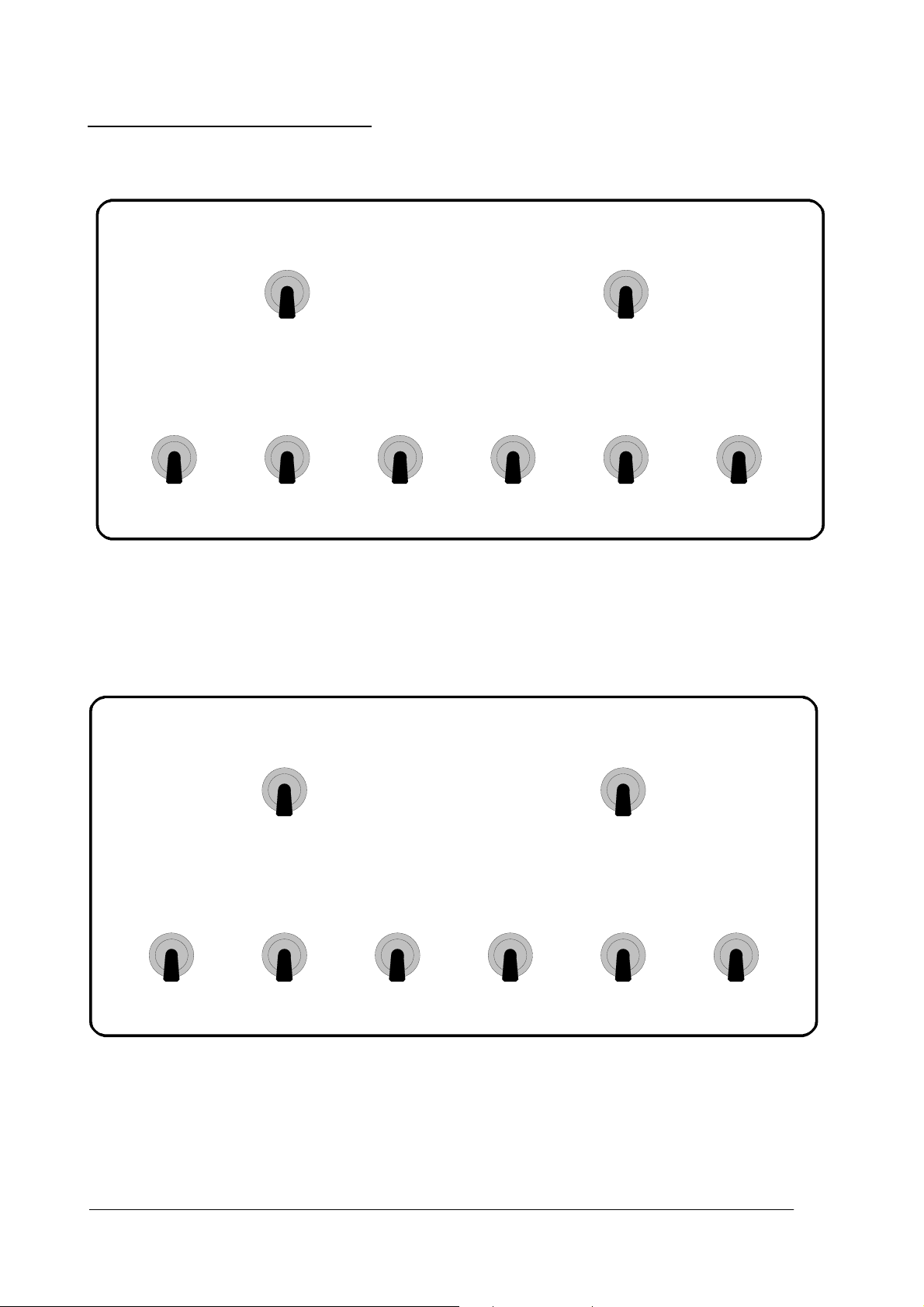
DIP-switch assignment, Boat
1 2 3 4 5 6 7 8
Model Model Model Flickering
Transmitter-
light
Typ
Transmitter-
type
Nauti-
error
correction
Model type
:
Fishing boat:
1 2 3 4 5 6 7 8
off off off
Power-driven vessel:
1 2 3 4 5 6 7 8
on off off
Tug:
1 2 3 4 5 6 7 8
off on off
Tug with Voith-Schneider power unit:
1 2 3 4 5 6 7 8
on on off
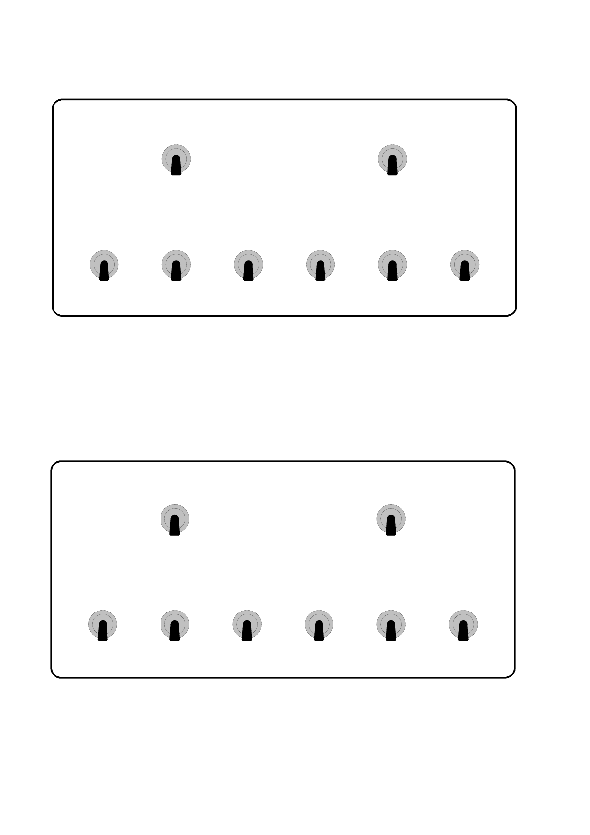
Flickering light
:
Single flash:
1 2 3 4 5 6 7 8
off
Double flash
1 2 3 4 5 6 7 8
on
Nautic-module-type:
Graupner:
1 2 3 4 5 6 7 8
off off
Robbe:
1 2 3 4 5 6 7 8
on off
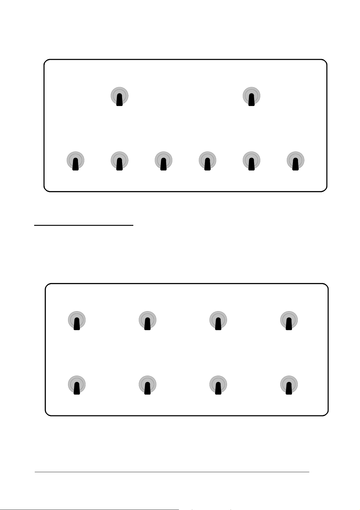
Nautic error correction
:
Error correction off:
1 2 3 4 5 6 7 8
off
Error correction on:
1 2 3 4 5 6 7 8
on
11
GRAUPNER GmbH & Co. KG D-73230 KIRCHHEIM/TECK GERMANY
11
No liability for printing errors. Technical modifications reserved. #0061368 12/2009
Page 12

DIP-switch assignment , Vehicle
1 2 3 4 5 6 7 8
Model Model Model Autom.
Panoramic
warning
flasher
light
variant
Transmitter
type
Transmitter
typ
Nautic-
error-
correktion
Model type
:
Truck:
1 2 3 4 5 6 7 8
off on on
Automatic warning flasher
:
Automatic warning flasher when reversing, off:
1 2 3 4 5 6 7 8
off
Automatic warning flasher when reversing, on:
1 2 3 4 5 6 7 8
on
Panoramic light variant
:
Four-channel panoramic light at outputs 13 - 16:
1 2 3 4 5 6 7 8
off
Four different warning lights at outputs 13 - 16:
1 2 3 4 5 6 7 8
on
Transmitter type
:
Graupner:
1 2 3 4 5 6 7 8
off off
Robbe:
1 2 3 4 5 6 7 8
on off
Nautic error correction
:
Error correction off:
1 2 3 4 5 6 7 8
off
Error correction on:
1 2 3 4 5 6 7 8
on
12
GRAUPNER GmbH & Co. KG D-73230 KIRCHHEIM/TECK GERMANY
12
No liability for printing errors. Technical modifications reserved. #0061368 12/2009
Page 13

DIP-switch assignment, Aircraft
1 2 3 4 5 6 7 8
Model Model Model Running
Panoramic
light
variant
light
varaint
Transmitter
type
Transmitter
type
Model type
:
Helicopter / Fixed-wing aircraft:
1 2 3 4 5 6 7 8
off off on
Ufo:
1 2 3 4 5 6 7 8
on off on
Running light variant (UFO only)
:
right Æ left
1 2 3 4 5 6 7 8
off
right Æ left Æ right
1 2 3 4 5 6 7 8
on
Panoramic light variant
:
Four-channel panoramic light at outputs 13 - 16:
1 2 3 4 5 6 7 8
off
Four different warning lights at outputs 13 - 16:
1 2 3 4 5 6 7 8
on
Transmitter type
:
Graupner:
1 2 3 4 5 6 7 8
off off
Robbe:
1 2 3 4 5 6 7 8
on off
13
GRAUPNER GmbH & Co. KG D-73230 KIRCHHEIM/TECK GERMANY
13
No liability for printing errors. Technical modifications reserved. #0061368 12/2009
Page 14

Fishing boat
Side light
Anchor light
Panoramic light, red, top
Panoramic light, green, top
Output 1 2 3 4 5 6 7 8 9 10 11 12 13 14 15 16
Switch, Graupner 4108 Assignment
Switch 1 top Searchlight 1 x
Switch 1 bottom Servo 1 x
Switch 2 top Searchlight 2 x
Switch 2 bottom Servo 2 x
Switch 3 top Flickering light x
Switch 3 bottom Universal output 1 x
Switch 4 top Running x x x
Switch 4 bottom At anchor x
Switch 5 top Fishing x x
Switch 5 bottom Grounded x x x
Switch 6 top
Switch 6 bottom vessel not under command x x
Switch 7 top Universal output 2 x
Switch 7 bottom Universal output 3 x
Switch 8 top Universal output 4 x
Switch 8 bottom Universal output 5 x
Panoramic light ,red, bottom
Panoramic light, white, bottom
Stern light
Masthead light
Universal output 1
Universal output 2
Universal output 3
Universal output 4
Searchlight 1
Searchlight 2
Universal output 5
Servo 1
Flickering light
GRAUPNER GmbH & Co. KG D-73230 KIRCHHEIM/TECK
GERMANY
Servo 2
Page 15

power-driven vessel
Servo 1
Side light
Anchor light
Panoramic light, red, top
Panoramic light, red, centre
Panoramic light, red, bottom
Panoramic light, white, centre
Output 1 2 3 4 5 6 7 8 9 10 11 12 13 14 15 16
Switch, Graupner 4108 Assignment
Switch 1 top Searchlight 1 x
Switch 1 bottom Servo 1 x
Switch 2 top Searchlight 2 x
Switch 2 bottom Servo 2 x
Switch 3 top Flickering light x
Switch 3 bottom Universal output 1 x
Switch 4 top Running x x x
Switch 4 bottom At anchor x
Switch 5 top Draught impeded x x x
Switch 5 bottom Grounded x x x
restricted in the ability to
Switch 6 top
Switch 6 bottom vessel not under command x x
Switch 7 top Universal output 2 x
Switch 7 bottom Universal output 3 x
Switch 8 top Universal output 4 x
Switch 8 bottom Universal output 5 x
manoeuvre x x x
Stern light
Masthead light
Universal output 1
Universal output 2
Universal output 3
Universal output 4
Searchlight 1
Searchlight 2
Universal output 5
Flickering light
Servo 2
GRAUPNER GmbH & Co. KG D-73230 KIRCHHEIM/TECK
GERMANY
Page 16

Tug
Servo 1
Anchor light
Masthead light 1
Panoramic light, red, top
Panoramic light, red, centre
Panoramic light, red, bottom
Panoramic light, white, centre
Output 1 2 3 4 5 6 7 8 9 10 11 12 13 14 15 16
Switch, Graupner 4108 Assignment
Switch 1 top Searchlight 1 x
Switch 1 bottom Servo 1 x
Switch 2 top Searchlight 2 x
Switch 2 bottom Servo 2 x
Switch 3 top Flickering light x
Switch 3 bottom Universal output 4 x
Switch 4 top Running x x
Switch 4 bottom At anchor x
Switch 5 top Towing x x x x
Switch 5 bottom Assisting x x x
restricted in the ability to
Switch 6 top
Switch 6 bottom vessel not under command x x
Switch 7 top Universal output 1 x
Switch 7 bottom Universal output 2 x
Switch 8 top Universal output 3 x
Switch 8 bottom Grounded x x x
manoeuvre x x x
Side light / Stern light
Towing light
Masthead light 2
Universal output 1
Universal output 2
Searchlight 1
Searchlight 2
Universal output 3
Universal output 4
Flickering light
Servo 2
GRAUPNER GmbH & Co. KG D-73230 KIRCHHEIM/TECK
GERMANY
Page 17

Tug with Voith-Schneider power unit
Servo 1
Anchor light
Masthead light 1
Panoramic light, red, top
Panoramic light, red, centre
Panoramic light, red, bottom
Panoramic light, white, centre
Output 1 2 3 4 5 6 7 8 9 10 11 12 13 14 15 16
Switch, Graupner 4108 Assignment
Switch 1 top Searchlight 1 x
Switch 1 bottom Servo 1 x
Switch 2 top Searchlight 2 x
Switch 2 bottom Servo 2 x
Switch 3 top Flickering light x
Switch 3 bottom
Switch 4 top Running x x s s
Switch 4 bottom At anchor x
Switch 5 top Towing x x x x s s s s
Switch 5 bottom Assisting x x x s s s
restricted in the ability to
Switch 6 top
Switch 6 bottom vessel not under command x x
Switch 7 top
Switch 7 bottom
Switch 8 top
Switch 8 bottom Grounded x x x
manoeuvre
x x x
Side light / Stern light
Towing light
Masthead light 2
Masthead light 1, mirrored
Side light / Stern light, mirrored
Searchlight 1
Searchlight 2
Flickering light
Towing light, mirrored
Masthead light 2, mirrored
Servo 2
GRAUPNER GmbH & Co. KG D-73230 KIRCHHEIM/TECK
GERMANY
Page 18

Truck
Servo 1
Parking light
Full beam
Dipped beam
Foglight
Interior light
Rear fog lamp
Left flasher
Right flasher
Universal output 1
Universal output 2
Brake light
Reversing light
Panoramic light 1/4
Panoramic light 2/4
Panoramic light 3/4
Panoramic light 4/4
Servo 2
Output 1 2 3 4 5 6 7 8 9 10 11 12 13 14 15 16
Switch, Graupner 4108 Assignment
Switch 1 top Parking light x
Switch 1 bottom Dipped beam x
Switch 2 top Full beam x
Switch 2 bottom Interior light x
Switch 3 top Foglight x
Switch 3 bottom Rear foglight x
Switch 4 top Universal output 1 x
Switch 4 bottom Universal output 2 x
Switch 5 top Servo 1, left x
Switch 5 bottom Servo 1, right x
Switch 6 top Servo 2, left x
Switch 6 bottom Servo 2, right x
Switch 7 top Left flasher x
Switch 7 bottom Warning flasher x x
Switch 8 top Right flasher x
Switch 8 bottom Panoramic light x x x x
Page 19

Helicopter / Fixed-wing aircraft
Searchlight
Tail light (white)
Anti-collision flasher 2 (white)
Anti-collision flasher 2 (white)
Anti-collision flasher 3 (white)
Anti-collision flasher 1 double (white)
Anti-collision flasher 1 double (white)
Output 1 2 3 4 5 6 7 8 9 10 11 12 13 14 15 16
Slider, Graupner Assignment
Proportional signal < 1.2ms All lamps off
Proportional signal > 1.2ms Navigation lamps and tail light x x x
Proportional signal > 1.4ms Panoramic light / Beacon x x x x x x x
Proportional signal > 1.6ms Anti-collision flasher x x x x x x x x x x x x x x x
Proportional signal > 1.8ms Searchlight x x x x x x x x x x x x x x x x
Proportional signal > 1.9ms Servos x x x x x x x x x x x x x x x x x x
Anti-collision flasher 4 (red)
Anti-collision flasher 3 (white)
Navigation lamp, left (red)
Anti-collision flasher 4 (red)
Navigation lamp, right (green)
Panoramic light 1/4
Panoramic light 2/4
Panoramic light 3/4
Panoramic light 4/4
Servo 1 (Searchlight)
GRAUPNER GmbH & Co. KG D-73230 KIRCHHEIM/TECK
GERMANY
Servo 2 (Landing searchlight)
Page 20

UFO
Searchlight
Running light 1/8
Running light 2/8
Running light 3/8
Running light 4/8
Running light 5/8
Running light 6/8
Running light 7/8
Running light 8/8
Navigation lamp, left (red)
Output 1 2 3 4 5 6 7 8 9 10 11 12 13 14 15 16
Slider, Graupner Assignment
Proportional signal < 1.2ms All lamps off
Proportional signal > 1.2ms Navigation lamps and tail light x x x
Proportional signal > 1.4ms Panoramic light / Beacon x x x x x x x
Proportional signal > 1.6ms Anti-collision flasher x x x x x x x x x x x x x x x
Proportional signal > 1.8ms Searchlight x x x x x x x x x x x x x x x x
Proportional signal > 1.9ms Servos x x x x x x x x x x x x x x x x x x
Tail light (white)
Navigation lamp, right (green)
Panoramic light 1/4
Panoramic light 2/4
Panoramic light 3/4
Panoramic light 4/4
Servo 1 (Searchlight)
Servo 2 (Landing searchlight)
GRAUPNER GmbH & Co. KG D-73230 KIRCHHEIM/TECK
GERMANY
Page 21

Fishing boat
Servo 1
Side light
Anchor light
Panoramic light, red, top
Panoramic light, green, top
Output 1 2 3 4 5 6 7 8 9 10 11 12 13 14 15 16
Switch, Robbe 8369 Assignment
Switch 1 top Searchlight 2 x
Switch 1 bottom Servo 2 x
Switch 2 top Fishing x x
Switch 2 bottom Grounded x x x
Switch 3 top Running x x x
Switch 3 bottom At anchor x
Switch 4 top Searchlight 1 x
Switch 4 bottom Servo 1 x
Switch 5 top Universal output 2 x
Switch 5 bottom Universal output 3 x
Switch 6 top Universal output 4 x
Switch 6 bottom Universal output 5 x
Switch 7 top
Switch 7 bottom vessel not under command x x
Switch 8 top Flickering light x
Switch 8 bottom Universal output 1 x
Panoramic light, red, bottom
Panoramic light, white, bottom
Stern light
Masthead light
Universal output 1
Universal output 2
Universal output 3
Universal output 4
Searchlight 1
Searchlight 2
Universal output 5
Flickering light
Servo 2
GRAUPNER GmbH & Co. KG D-73230 KIRCHHEIM/TECK
GERMANY
Page 22

power-driven vessel
Servo 1
Side light
Anchor light
Panoramic light, red, top
Panoramic light, red, centre
Panoramic light, red, bottom
Panoramic light, white, centre
Output 1 2 3 4 5 6 7 8 9 10 11 12 13 14 15 16
Switch, Robbe 8369 Assignment
Switch 1 top Searchlight 2 x
Switch 1 bottom Servo 2 x
Switch 2 top Draught impeded x x x
Switch 2 bottom Grounded x x x
Switch 3 top Running x x x
Switch 3 bottom At anchor x
Switch 4 top Searchlight 1 x
Switch 4 bottom Servo 1 x
Switch 5 top Universal output 2 x
Switch 5 bottom Universal output 3 x
Switch 6 top Universal output 4 x
Switch 6 bottom Universal output 5 x
restricted in the ability to
Switch 7 top
Switch 7 bottom vessel not under command x x
Switch 8 top Flickering light x
Switch 8 bottom Universal output 1 x
manoeuvre x x x
Stern light
Masthead light
Universal output 1
Universal output 2
Universal output 3
Universal output 4
Searchlight 1
Searchlight 2
Universal output 5
Flickering light
Servo 2
GRAUPNER GmbH & Co. KG D-73230 KIRCHHEIM/TECK
GERMANY
Page 23

Tug
Servo 1
Anchor light
Masthead light 1
Panoramic light, red, top
Panoramic light, red, centre
Panoramic light, red, bottom
Panoramic light, white, centre
Output 1 2 3 4 5 6 7 8 9 10 11 12 13 14 15 16
Switch, Robbe 8369 Assignment
Switch 1 top Searchlight 2 x
Switch 1 bottom Servo 2 x
Switch 2 top Towing x x x x
Switch 2 bottom Assisting x x x
Switch 3 top Running x x
Switch 3 bottom At anchor x
Switch 4 top Searchlight 1 x
Switch 4 bottom Servo 1 x
Switch 5 top Universal output 1 x
Switch 5 bottom Universal output 2 x
Switch 6 top Universal output 3 x
Switch 6 bottom Grounded x x x
restricted in the ability to
Switch 7 top
Switch 7 bottom vessel not under command x x
Switch 8 top Flickering light x
Switch 8 bottom Universal output 4 x
manoeuvre x x x
Side light / Stern light
Towing light
Masthead light 2
Universal output 1
Universal output 2
Searchlight 1
Searchlight 2
Universal output 3
Universal output 4
Flickering light
Servo 2
GRAUPNER GmbH & Co. KG D-73230 KIRCHHEIM/TECK
GERMANY
Page 24

Tug with Voith-Schneider power unit
Servo 1
Anchor light
Masthead light 1
Panoramic light, red, top
Panoramic light, red, centre
Panoramic light, red, bottom
Panoramic light, white, centre
Output 1 2 3 4 5 6 7 8 9 10 11 12 13 14 15 16
Switch, Robbe 8369 Assignment
Switch 1 top Searchlight 2 x
Switch 1 bottom Servo 2 x
Switch 2 top Towing x x x x s s s s
Switch 2 bottom Assisting x x x s s s
Switch 3 top Running x x s s
Switch 3 bottom At anchor x
Switch 4 top Searchlight 1 x
Switch 4 bottom Servo 1 x
Switch 5 top
Switch 5 bottom
Switch 6 top
Switch 6 bottom Grounded x x x
restricted in the ability to
Switch 7 top
Switch 7 bottom vessel not under command x x
Switch 8 top Flickering light x
Switch 8 bottom
manoeuvre x x x
Side light / Stern light
Towing light
Masthead light 2
Masthead light 1, mirrored
Side light / Stern light, mirrored
Searchlight 1
Searchlight 2
Flickering light
Towing light, mirrored
Masthead light 2, mirrored
Servo 2
GRAUPNER GmbH & Co. KG D-73230 KIRCHHEIM/TECK
GERMANY
Page 25

Truck
Servo 1
Parking light
Full beam
Dipped beam
Foglight
Interior light
Rear fog lamp
Left flasher
Right flasher
Universal output 1
Universal output 2
Brake light
Reversing light
Panoramic light 1/4
Panoramic light 2/4
Panoramic light 3/4
Panoramic light 4/4
Servo 2
Output 1 2 3 4 5 6 7 8 9 10 11 12 13 14 15 16
Switch, Robbe 8369 Assignment
Switch 1 top Right flasher x
Switch 1 bottom Panoramic light x x x x
Switch 2 top Servo 2, left x
Switch 2 bottom Servo 2, right x
Switch 3 top Servo 1, left x
Switch 3 bottom Servo 1, right x
Switch 4 top Left flasher x
Switch 4 bottom Warning flasher x x
Switch 5 top Universal output 1 x
Switch 5 bottom Universal output 2 x
Switch 6 top Foglight x
Switch 6 bottom Rear foglight x
Switch 7 top Full beam x
Switch 7 bottom Interior light x
Switch 8 top Parking light x
Switch 8 bottom Dipped beam x
Page 26

Helicopter / Fixed-wing aircraft
Searchlight
Tail light (white)
Anti-collision flasher 2 (white)
Anti-collision flasher 2 (white)
Anti-collision flasher 3 (white)
Anti-collision flasher 1 double (white)
Anti-collision flasher 1 double (white)
Output 1 2 3 4 5 6 7 8 9 10 11 12 13 14 15 16
Slider, Robbe Assignment
Proportional signal > 1.8ms All lamps off
Proportional signal < 1.8ms Navigation lamps and tail light x x x
Proportional signal < 1.6ms Panoramic light / Beacon x x x x x x x
Proportional signal < 1.6ms Anti-collision flasher x x x x x x x x x x x x x x x
Proportional signal < 1.2ms Searchlight x x x x x x x x x x x x x x x x
Proportional signal < 1.1ms Servos x x x x x x x x x x x x x x x x x x
Anti-collision flasher 4 (red)
Anti-collision flasher 3 (white)
Navigation lamp, left (red)
Anti-collision flasher 4 (red)
Navigation lamp, right (green)
Panoramic light 1/4
Panoramic light 2/4
Panoramic light 3/4
Panoramic light 4/4
Servo 1 (Searchlight)
Servo 2 (Landing searchlight)
GRAUPNER GmbH & Co. KG D-73230 KIRCHHEIM/TECK
GERMANY
Page 27

UFO
Searchlight
Running light 1/8
Running light 2/8
Running light 3/8
Running light 4/8
Running light 5/8
Running light 6/8
Running light 7/8
Running light 8/8
Navigation lamp, left (red)
Output 1 2 3 4 5 6 7 8 9 10 11 12 13 14 15 16
Slider, Robbe Assignment
Proportional signal > 1.8ms All lamps off
Proportional signal < 1.8ms Navigation lamps and tail light x x x
Proportional signal < 1.6ms Panoramic light / Beacon x x x x x x x
Proportional signal < 1.6ms Running light x x x x x x x x x x x x x x x
Proportional signal < 1.2ms Searchlight x x x x x x x x x x x x x x x x
Proportional signal < 1.1ms Servos x x x x x x x x x x x x x x x x x x
Tail light (white)
Navigation lamp, right (green)
Panoramic light 1/4
Panoramic light 2/4
Panoramic light 3/4
Panoramic light 4/4
Servo 1 (Searchlight)
Servo 2 (Landing searchlight)
GRAUPNER GmbH & Co. KG D-73230 KIRCHHEIM/TECK
GERMANY
No liability for printing errors. Technical modifications reserved. #0061199
12/2009
Page 28

Power-driven
vessel
drought
impeded
4108
RAM
TUG
4108
RAM
Assistierend
Tug with
Voith-Schneider
4108
RAM
Assisting
Vehicle
S 1 left
S 2 right
4108
S 1 left
S 1 right
Ø
Ø
Ø
Ø
Fishing boat
NUC
4108
Ø
NUC
NUC
NUC
1
2
3
4
5
6
7
8
Fishing boat
NUC
Ø
Power-driven vessel
TUG
Tug with Voith-Schneider
Vehicle
S 1 left
S 2 right
S 2 left
S 1 right
1
2
3
4
5
6
7
8
NUC
1
2
3
4
5
6
7
8
1
2
3
4
5
6
7
8
NUC
drought
impeded
NUC
RAM
Towing
Assisting
NUC
RAM
Towing
Assisting
Graupner
Futaba
To Print
Ø
Ø
 Loading...