

Page 1
Graupner | iFS Sendemodul für Multiplex PROFI
Best.-Nr. 23108
Installation und Gebrauch
Seite 2
Graupner | iFS RF Module for Multiplex PROFI
item number 23108
Installation and Usage
Page 14
Module HF Graupner | iFS pour Multiplex PROFI
N° 23108
Installation et mode d’emploi
Page 26
GRAUPNER GmbH & Co. KG - Postfach 1242 - 73220 Kirchheim/Teck - www.graupner.de
Page 2
Das verwendete Material, einschließlich, aber nicht beschränkt auf, Fotografien, Texte und Kon-
!
zepte in dieser Anleitung stehen unter Copyright ©2006-2007. Eine Verbreitung der Daten ohne
Genehmigung ist strengstens verboten!
AUF GRUND REGELMÄSSIGER ÄNDERUNGEN DARF DIESE INFORMATION WEDER GEPOSTET, HOCHGELADEN NOCH IN IRGEND EINER ANDEREN FORM ÜBER DAS INTERNET VERBREITET WERDEN.
Alle Rechte weltweit vorbehalten.
Einführung
Vielen Dank, dass Sie das Graupner | iFS-System gekauft haben. Dieses System ist ein direkter
Ersatz für Ihr Serien-HF-Modul und Ihren Empfänger.
Bitte lesen Sie vorab die gesamte Anleitung bevor Sie versuchen, das Graupner | iFS-System
zu installieren bzw. einzusetzen.
Voraussetzungen für den Einbau
Die Installation des Graupner | iFS-HF-Moduls ist nicht schwierig.
Die Anleitung sollte ausreichende und klare Informationen für den Einbau und den Gebrauch des
Systems bieten.
Haftung
Durch den Gebrauch der Anlage stimmen Sie zu, Graupner GmbH & Co. KG von jeglicher Haftung
freizustellen.
Rechtliche Informationen
Die Funktion sowie das Erscheinungsbild dieses Systems sind durch deutsche, sowie US-Copyright-Rechte geschützt. Diverse Terminologien und Bezeichnungen stehen unter deutschem und/
oder US Warenzeichen-Recht.
2
Page 3
1. Entfernen des bisherigen HF-Moduls
Legen Sie Ihren Sender mit der Vorderseite auf ein Handtuch oder einen anderen weichen Untergrund, um ihn zu schützen. Schieben Sie die beiden Verschlüsse abwärts, um die Rückseite zu
öffnen. Legen Sie die Rückseite zur Seite. Entfernen Sie das HF-Teil, indem Sie beide Seiten der
Platine greifen und das HF-Teil senkrecht nach oben abziehen. Das HF-Teil wird für diese Umrüstung nicht mehr benötigt. Beachten Sie hierzu Bild 1
Bild 1
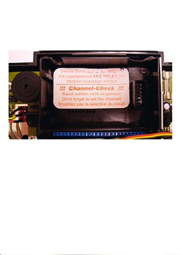
Schneiden sie ein Loch in das Warnetikett. Dies ist nötig, damit das Antennenkabel durch das
Gehäuse passt. Beachten Sie Bild 2.
3
Page 4

Bild 2
2. Entfernen der Antennenhalterung
Entfernen sie die ursprüngliche Antennenhalterung, indem sie die 4 schwarzen Schrauben mit
einem Kreuzschlitzschraubenzieher herausdrehen. Beachten sie dazu bitte Bild 3.
Bild 3
4
Page 5
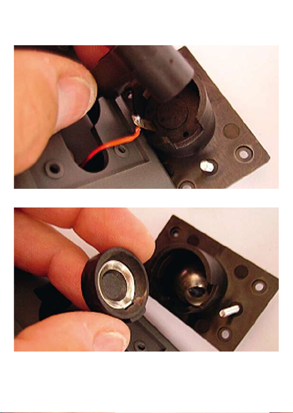
Entfernen sie die einzig übrig bleibende Schraube mit einem Schlitzschraubenzieher. Diese
Schraube ist für die Einstellung des Drucks auf die Kugel zuständig. Entfernen Sie die Druckplatte
und lösen Sie die Antennengrundplatte von der Antennenhalterung. Beachten Sie Bild 4 und 5.
Bild 4
Bild 5
5
Page 6
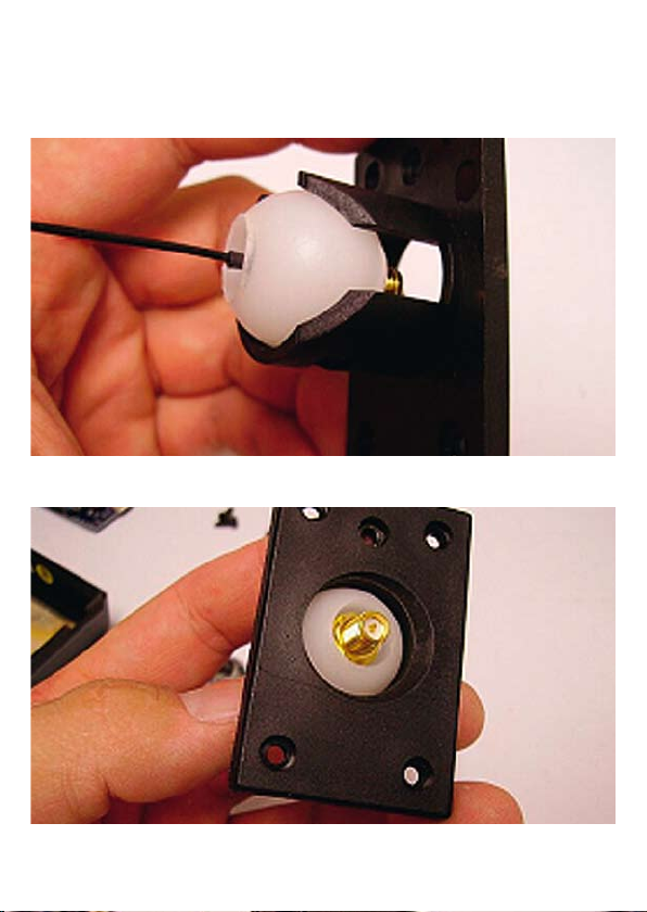
Entfernen sie die Metallkugel aus der Antennenhalterung. Sollten sie die Kugel später brauchen,
um die ursprüngliche Konfiguration wiederherzustellen, sollten sie diese gut aufbewahren. Für
diesen Umbau wird die Kugel nicht mehr benötigt. Setzen sie die mitgelieferte Plastikkugel in
den Antennenschacht ein, so dass die Antennenschraubverbindung nach oben zeigt. Beachten
Sie hierzu Bild 6 und 7.
Bild 6
Bild 7
6
Page 7
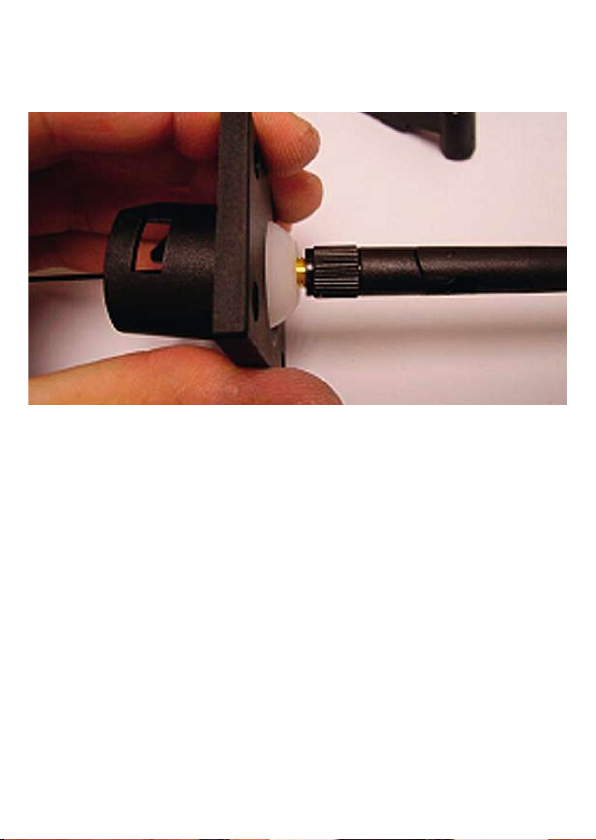
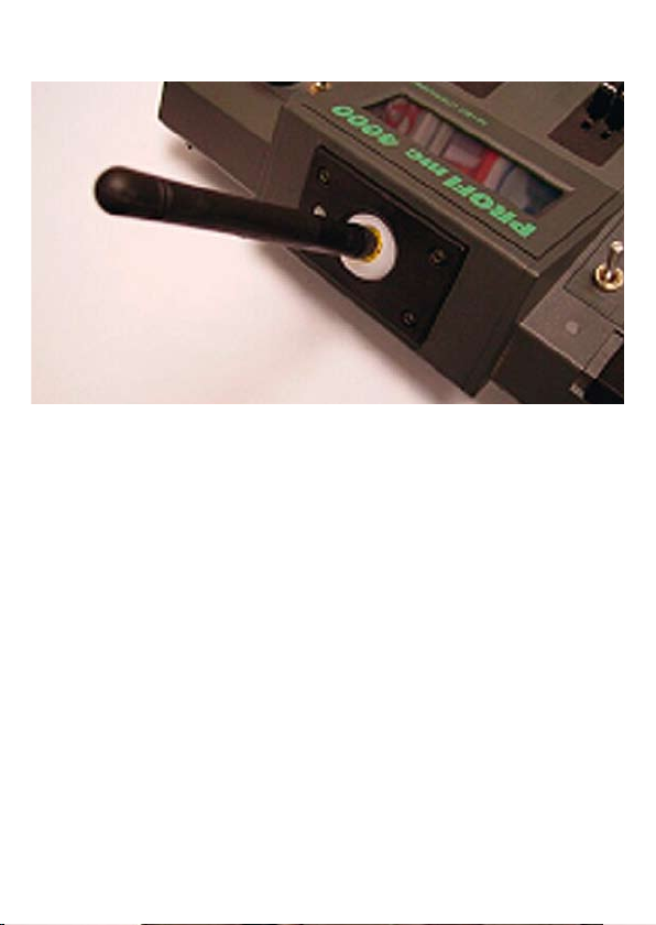
Schrauben sie die ebenfalls mitgelieferte Antenne (einige Umdrehungen) auf die Plastikkugel. Ziehen Sie die Plastikkugel an der Antenne durch die Antennenhalterung. Achten sie hierbei darauf,
dass die Antenne fest genug angezogen ist. Die Kugel wird möglicherweise festsitzen und kann
nicht weiter geschoben werden.Beachten Sie Bild 8.
Bild 8
7
Page 8
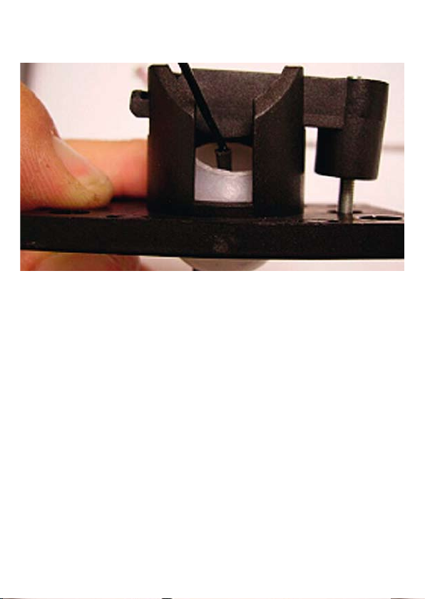
Schrauben sie nun die Antenne ab und legen sie diese zur Seite. Setzen Sie die Antennenhalterung
wieder an, indem die Druckplatte in die richtige Position gebracht wird. Ziehen Sie diese - wie in
Bild 9 gezeigt - fest.
Bild 9
Wenn Sie möchten, können Sie die Feder weglassen, weil die Kugel nicht fest an Ihrem Platz gehalten wird und keine Federspannung bei dieser Installation notwendig ist.Ein erneutes Anbringen
ist nicht notwendig. Falls doch, dient diese Methode lediglich dazu, alle originalen Teile an Ihrem
Platz zu behalten, um sie nicht zu verlieren.
Die ursprüngliche Antennenhalterung muss von allen elektronischen Teilen elektrisch isoliert sein.
Wir empfehlen einen Schrumpfschlauch oder Klebeband wie in Bild 10 gezeigt.
8
Page 9
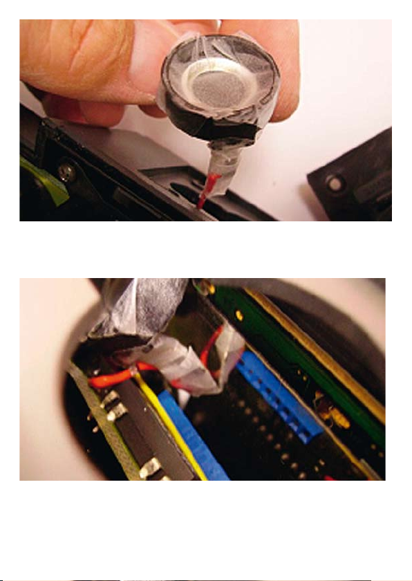
Bild 10
Ziehen Sie die Antennenhalterung nach innen in den Sender. Siehe Bild 11
Bild 11
9
Page 10
Schrauben Sie die Antennenhalterung mit den 4 originalen schwarzen Schrauben an das Sendergehäuse. Beachten Sie Bild 12.
Bild 12
10
Page 11
3. Installation des Graupner | iFS Sendemoduls
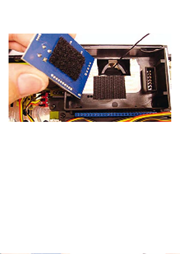
In Ihrem Umrüstsatz befinden sich selbstklebende Haken- und Schlaufenbänder. Fixieren Sie die
flauschige Seite auf der Unterseite des Graupner|iFS HF-Moduls. Kleben Sie die andere (Haken-)
Seite an die Stelle an die das iFS-Modul montiert werden soll. Beachten Sie Bild 13.
Bild 13
Achtung!
Dieser Schritt ist der kritischste während der Installation dieses Produkts und gibt
Ihnen entweder Erfolg und Reichweite oder Mißerfolg während des Betriebes mit
diesem Produkt.
Sie müssen den Koax-Antennenanschluß auf den entsprechenden Anschluß auf der iFS-Platine
aufbringen. Um dies richtig zu tun, muß der Kabelanschluß direkt über den runden Anschluß der
Platine gesetzt werden und dann fest nach unten gedrückt werden. Jeder Winkel, also Versatz
zwischen Stecker und Buchse, kann den Anschluß zerstören, deshalb ist es wichtig, dass Sie
gerade nach unten drücken und keinesfalls schräg. In den meisten Fällen werden Sie ein „Klick“Geräusch hören, wenn der Stecker in die Buchse einrastet. Beachten Sie Bild 14 und achten Sie
insbesondere auf die Ausrichtung des Kabels in Bezug auf die Platine. Das Kabel verläßt die
Platine auf der linken Seite wie in Bild 14 gezeigt.
11
Page 12
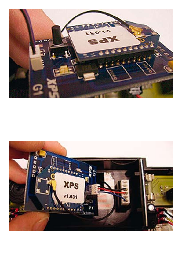
Bild 14
Setzen Sie die Graupner | iFS HF-Platine über den originalen Einbauort des HF-Teils. Stecken Sie
den weißen Stecker in den originalen HF-Steckplatz und drücken Sie ihn fest. Bewegen Sie den
Stecker hin- und her, bis er absolut fest sitzt. Beachten Sie Bild 15 und insbesondere die Farben
der Verbindungsdrähte, sowie die Positionen von Antennenkabel und Graupner | iFS Modul.
Bild 15
12
Page 13

Drücken Sie nun das HF-Teil an seinen Platz (auf das Schlaufenband). Sie können das Modul
etwas hin- und her wackeln, damit es richtig sitzt und sich nicht während des Betriebes selbstständig macht. Beachten Sie Bild 16.
Bild 16
Anmerkung:
Wenn Sie wieder auf Ihr bisheriges HF-Modul zurückrüsten möchten, vergessen Sie nicht, die Antenne anzuschliessen. Anderenfalls könnte ein Defekt an Ihrem Sender auftreten! Das Hakenband
kann in diesem Fall montiert bleiben.
Der Einbau ist nun abgeschlossen. Nach Einschalten Ihres PROFI Senders sollte die LED kurz
orange (rot und grün gleichzeitig) aufleuchten und dann anfangen rot zu blinken. Falls dies nicht
der Fall sein sollte, schalten Sie den Sender wieder aus und vergewissern Sie sich, dass das
Verbindungskabel nicht falsch herum eingesteckt worden ist. In diesem Fall tritt kein Schaden auf,
stecken Sie das Kabel einfach richtig herum wieder ein und schalten Sie erneut ein. Sollte die LED
nicht wie beschrieben leuchten, kontaktieren Sie unsere Serviceabteilung.
Die Programmierung des Sendemoduls muss mit abgenommener Rückwand erfolgen, um Zugang zum Programmierschalter zu haben und die LED zu sehen. Hinweise: Die GRAUPNER |
iFS-PROFI-Sendemodule sind ab Werk so programmiert, dass für einen Betrieb in Europa keine
Änderungen an den Einstellungen vorgenommen werden müsssen. Bitte beachten Sie, dass die
iFS-Antenne sorgfältig gelöst wird, z.B. für einen Reichweitentest. Die Antenennkugel wird nicht
stark festgehalten und kann sich drehen und dabei z.B. den Antennenanschluß zerstören.
13
Page 14

All material including, but not limited to photographs, text, and concepts contained in this manual
!
is copyright ©2006-2007. Distribution of this data without permission is strictly prohibited!
DUE TO FREQUENT CHANGES, DO NOT POST, UPLOAD, OR OTHERWISE
PROVIDE THIS INFORMATION VIA ANY INTERNET SITE!
All rights reserved, worldwide.
Introduction
Thank you for purchasing the Graupner|iFS-System. This system is a direct replacement for your
stock RF module and receiver.
Please read through this entire manual before you attempt the installation and usage of your
Graupner | iFS-System!
Installation Requirements
The installation of the Graupner | iFS-System RF module is not difficult.
This manual should provide ample information and clarity to install and use this product.
Liability
By using this product, you agree to hold Graupner GmbH & Co. KG Power Systems free from any
type of liability either directly or indirectly while using this product.
Legal Information
The ‘look and feel’ and functionality of this product are protected by German and U.S. copyright
laws. Various terminology and feature names are protected under German and/or U.S. trademark
laws.
14
Page 15

1. Removing the stock RF module
Lay your transmitter face down on a towel or something similar to protect it. Press the two latch
buttons on the top of the transmitter and remove the back of the case. Set the back aside. Locate the
stock RF module and remove it. Save the module in case you need it in the future (returning your
system back to the stock configuration). It will not be re-installed with this upgrade.
See Figure 1.
Figure 1
Cut a hole in the warning label. This is necessary so that the antenna wire can pass through the
housing. See Figure 2 for details.
15
Page 16

Figure 2
2. Disassembling the stock antenna block
Remove the stock antenna block by removing the 4 black screws using a Philips screwdriver.
See Figure 3 for details.
Figure 3
16
Page 17

Remove the single remain screw using a flat tipped screw driver. This screw is the ball tensioner.
Remove the tensioner arm and separate the antenna base from the antenna block.
See Figures 4 and 5 for details.
Figure 4
Figure 5
17
Page 18

Remove the metal ball from the antenna block. Save the ball if you need it in the future (returning
your system back to the stock configuration). The ball will not be re-installed with this upgrade.
Place the supplied plastic ball in the antenna block, so that the antenna connection is facing
upwards.See Figures 6 and 7 for details.
Figure 6
Figure 7
18
Page 19

Screw the antenna on the connector completely (several turns). Pull the ball through the antenna
block using the antenna. The ball will eventually stop and can not be pulled any further.
See Figure 8 for details.
Figure 8
19
Page 20

Unscrew and remove the antenna.
Reassemble the antenna block by placing the tensioner arm in place and tighten it as shown in
Figure 9.
Figure 9
You can leave out the spring if you like as the ball will not actually be held in place and tension
will not occur with this setup. Reassembly is not necessary; it just serves as a way to keep all of
the original parts without losing them.
The antenna base must be insulated from any electronics. We recommend large shrink tubing or
Blemderm™ tape, as shown in Figure 10.
20
Page 21

Figure 10
Tuck the antenna base inside of the transmitter, out of the way. See Figure 11.
Figure 11
21
Page 22

Attach the antenna block to the transmitter case using the original 4 black screws.
The final antenna installation is shown in Figure 12.
Figure 12
22
Page 23

3. Installing the Graupner | iFS-System RF Module
Included with your package you will find matching Velcro pairs. Attach the “fuzzy” side of the
Velcro to the Graupner | iFS-System RF module. Attach the other (hooked) piece of Velcro to the
place where the RF module will be mounted. See Figures 13 for details.
Figure 13
Caution!
This next step is the most critical in the installation of this product and will either
mean success or failure of the operation of this product.
You must attach the antenna’s cable connector to the u.FL connector on the Graupner | iFS-System
RF module. To do this, place the cable connector directly above the round connector the board and
press down firmly. Any amount of angle can destroy the cable connector, so it is important that you
press straight down, and not at an angle. In most all cases, you will hear a definitely “click” sound
as the cable connector is snapped in place.
Refer to Figure 14, and note the direction of the cable in reference to the board. The cable must exit
the left side of the board as shown in Figure 14.
23
Page 24

Figure 14
Position the Graupner | iFS-System RF module over the original RF module location. Insert the
white connector into the original RF port connector, and press firmly, rocking the connector back
and forth until it is seated fully.
Refer to Figure 15, noting the color of the wires and positions of antenna cable and the
Graupner | iFS-System RF module.
Figure 15
24
Page 25

Now, carefully press the module into place (on to the receiving Velcro). You can wiggle the module
to make sure it is seated properly and will not detach during normal use.
See Figure 16 for details.
Figure 16
Note:
If you switch back to a stock RF module, remember to re-install the antenna or damage may result
to the transmitter! You do not need to remove the Velcro to re-install the stock RF module.
Turning on the power to your Profi radio now should cause the LED on the Graupner | iFS-System
RF module to light up briefly orange, and then begin flashing red.
If this does not occur, turn off the radio and make sure that you do not have the connector installed
backwards! No damage will be done if you did, just reverse it and try powering on again. If the LED
does not light up at all, contact our Service Dept. for more information.
All programming must be done with the back of the transmitter off due to the location of the push
button switch and LED on the Graupner | iFS-System RF module
Useful hints: The GRAUPNER iFS-PROFI-RF modules are default configured for the use in Europe. So no changes to the settings should be necessary in most cases.
Please note that care must be taken when removing the antenna for range testing. The ball is not
held firmly in place and can rotate, destroying the cable connector!
25
Page 26

Tout matériel utilisé ici, mais non limité aux photographies, textes et concepts contenus dans ce
!
manuel est sujet aux droits d’auteur Copyright ©2006-2007. La distribution sans permission de
ce document est strictement interdite !
EN RAISON DE FREQUENTS CHANGEMENTS, CETTE INFORMATION NE
DOIT PAS ETRE POSTEE, TELECHARGEE OU MEME TRANSMISE PAR
SITE INTERNET SOUS QUELQUE FORME QU’ELLE SOIT !
Tous les droits sont réservés mondialement
Introduction
Nous vous remercions d’avoir acquis le système Graupner | iFS.
Ce système remplace directement votre module HF et votre récepteur.
Veuillez s.v.p. lire tout d’abord entièrement le manuel avant d’essayer d’installer et d’utiliser le
système Graupner | iFS !
Impératifs pour l’installation
L’installation du module HF du système Graupner | iFS n’est pas difficile.
Ce manuel devrait vous fournir d’amples informations précises pour installer et utiliser ce système.
Responsabilité
En utilisant ce produit, vous confirmez votre accord de dégager Graupner GmbH & Co.KG de toute
responsabilité directe ou indirecte telle qu’elle soit.
Information légale
L’apparence et le mode de fonctionnement de ce produit sont protégés par des droits d’auteur américains et allemands. Diverses terminologies et descriptions sont protégées sous le Droit allemand
et/ou américain des Marques déposées.
26
Page 27

1. Enlevez le module HF installé
Posez la face avant de votre émetteur sur une serviette ou quelque chose de similaire pour le protéger. Pressez les deux verrouillages pour ouvrir le fond du boîtier. Posez le fond sur le côté. Retirez
le module HF en saisissant les deux côtés de la platine et en le tirant vers le haut. Le module HF
ne sera plus nécessaire pour cette conversion.
Voir la Figure 1.
Fig. 1
Découper une ouverture dans l’étiquette d’avertissement. Ceci est nécessaire pour que le fil
d’antenne passe au travers du boîtier. Voir la Fig. 2
27
Page 28

Fig. 2
2. Démontage du support d’antenne
Démontez le support de l’antenne d’origine en retirant les 4 vis noires avec un tournevis cruciforme.Voir la Fig. 3
Fig. 3
28
Page 29

Retirez la seule vis restante avec un tournevis à lame. Cette vis sert au réglage de la pression sur la
rotule. Retirez la plaquette de pression et séparer la base du support de l’antenne.
Voir les Fig. 4 et 5.
Fig. 4
Fig. 5
29
Page 30

Retirez la rotule métallique du support de l’antenne. Si vous avez besoin ultérieurement de la rotule
pour une remise dans la configuration d’origine, conservez la soigneusement.
La rotule métallique ne sera plus nécessaire pour cette conversion.
Placez la rotule en plastique fournie dans le support de l’antenne de façon à ce que la connexion
soit orientée vers le haut. Voir les Fig. 6 et 7
Fig. 6
Fig. 7
30
Page 31

Vissez la nouvelle antenne également fournie (sur plusieurs tours) sur la rotule en plastique.
Poussez celle-ci dans le support en utilisant l’antenne. La rotule devra être bien fixée et ne pourra
plus être retirée.
Voir la Fig. 8
Fig. 8
31
Page 32

Dévissez l’antenne et mettez là de côté.
Assemblez à nouveau la plaquette de pression dans la bonne position et serrez la comme montré
sur la Fig. 9.
Fig. 9
Vous pouvez laisser le ressort de côté si vous voulez que la rotule ne soit pas trop serrée, ce qui
n’est pas nécessaire dans cette installation.
Un réassemblage n’est pas nécessaire, il servira seulement à conserver les pièces originales sans
risque de les perdre.
Le support d’antenne original devra être isolé de toutes les parties électriques. Nous conseillons
d’utiliser de la gaine thermo rétractable ou de la bande adhésive, comme montré sur la Fig. 10.
32
Page 33

Fig. 10
Tirez le support d’antenne vers l’intérieur dans l’émetteur.Fig. 11.
Fig. 11
33
Page 34

Vissez le support d’antenne avec les 4 vis noires originales dans le boîtier de l’émetteur, comme
montré sur la Fig. 12
Fig. 12
34
Page 35

3. Installation du module HF du système Graupner iFS
De la bande à crampons est fournie dans le kit de conversion. Fixez une bande sur le dessous du
module du système Graupner iFS et la contre partie (crampons) à l’emplacement où le module iFs
devra être monté. Voir la Fig. 13
Fig. 13
Attention !
La prochaine étape est la plus critique dans l’installation de ce produit et vous
apportera soit le succès ou l’échec durant son utilisation.
Vous devez relier de raccordement coaxial de l’antenne au raccordement sur la platine iFS. Pour
faire cela correctement, placez le raccordement du câble directement sur la connexion ronde de
la platine et pressez le fermement. Toute pression exercée de travers sur les connecteurs peut
détruire le raccordement, c’est pourquoi il est important d’exercer la pression bien verticalement et
en aucun cas de travers. Dans la plupart des cas un ‘’clic’ se fera entendre lorsque les connecteurs
seront crantés. Observez la fig. 14 et veillez particulièrement à l’alignement du câble par rapport à
la platine. Le câble doit sortir sur le côté gauche de la platine, comme montré sur la Fig. 14.
35
Page 36

Fig.14
Placez le module HF du système Graupner iFS à l’emplacement du module HF original. Reliez le
connecteur blanc à la place d’enfichage HF originale ; pressez le fermement et déplacez le d’avant
en arrière jusqu’à ce qu’il soit fermement fixé.
Référez vous à la Fig.15 montrant la couleur des fils de raccordement, ainsi que la position du
câble d’antenne et du module Graupner iFS
Fig. 15
36
Page 37

Pressez maintenant soigneusement le module à sa place (sur la bande à crampons). Vous pourrez
essayer de déplacer un peu le module pour vous assurer qu’il est correctement fixé sans risquer
de se détacher durant l’utilisation.Voir la Fig.16.
Fig. 16
Note :
Si vous voulez réinstaller le module HF original, n’oubliez pas d’échanger l’antenne, car autrement
l’émetteur pourra être détérioré. Dans ce cas, la bande à crampons pourra rester collée en place.
L’installation est ainsi terminée.
Mettez maintenant votre émetteur en contact. Le LED sur le module iFS doit s’allumer brièvement
en orange et clignoter ensuite en rouge.
Si cela ne se produit pas, coupez votre émetteur et assurez vous que la connexion n’a pas été
inversée. Aucun dommage ne sera causé en la rétablissant simplement Si le LED ne s’allume pas
du tout, contactez notre S.A.V pour davantage d’informations.
Conseils utiles : Le module GRAUPNER-PROFI iFS est programmé en usine de façon à ce
qu’aucune modification des réglages ne devra être effectuée pour son utilisation en Europe.
Veuillez noter que l’antenne iFS devra être soigneusement retirée, par ex. pour faire un essai de
portée.
La rotule ne devra pas être trop serrée et pouvoir tourner pour ne pas détériorer la connexion.
37
 Loading...