

Page 1
Manual
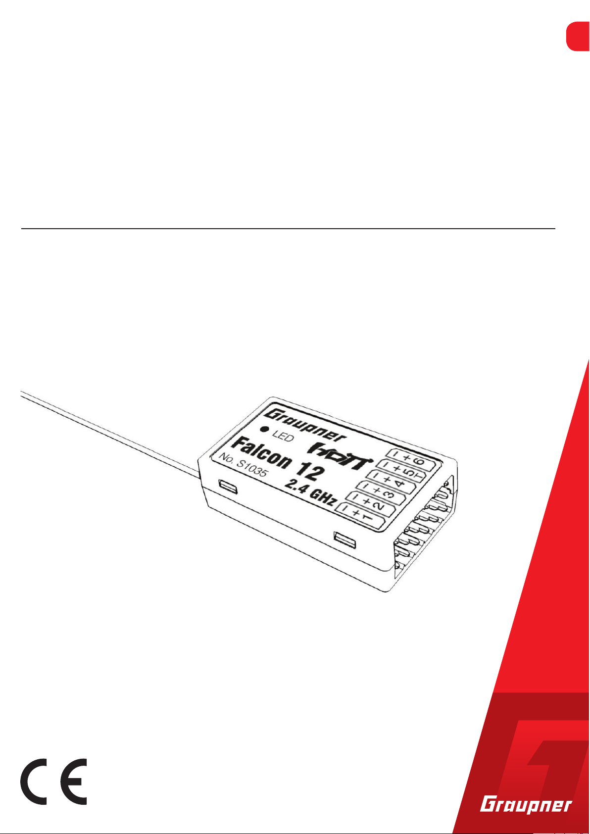
Falcon 12
HoTT 2.4 GHz receiver with 3 axis gyro
No. S1035
EN
Copyright © Graupner/SJ GmbH
Page 2
Index
Introduction ............................................................................. 4
Service Centre .......................................................................... 4
Intended use ............................................................................ 5
Target group ...................................................................................5
Package content ....................................................................... 5
Technical data .......................................................................... 5
Symbols explication ................................................................. 6
Safety notes.............................................................................. 6
Installation ............................................................................... 8
Fixed-wing model ...........................................................................8
Helicopter model ...........................................................................8
Binding ..................................................................................... 9
Interfaces ................................................................................. 9
Power supply ................................................................................10
Programming the receiver settings ....................................... 10
Receiver settings menu ...............................................................10
Programming a fixed-wing model ......................................... 12
Free mixers ...................................................................................12
Gyro assignment .................................................................... 14
Programming the regulation .................................................. 16
Gyro setting display .....................................................................16
Programming the axes sensitivity ................................................18
Initialization of the gyro ........................................................ 19
Adjust servolimit for channels ............................................... 19
Programming a helicopter model .......................................... 20
Preparing the helicopter ..............................................................20
2 / 36
Transmitter presettings ................................................................20
Initializing the gyro (helicopter) ..................................................20
Basic settings ......................................................................... 21
Axis assignment ..................................................................... 25
DO SETUP ....................................................................................25
Swashplate setting without Expertmode .............................. 26
S1035_Falcon_12_jh_V1
Page 3

Swashplate setting with Expertmode .................................... 27
Tail rotor setting without Expertmode .................................. 29
Tail rotor setting with Expertmode ....................................... 30
Firmware update .................................................................... 32
Declaration of conformity ...................................................... 33
Notes on environmental protection ...................................... 34
Care and maintenance ........................................................... 34
Warranty ................................................................................ 34
S1035_Falcon_12_jh_V1
3 / 36
Page 4
Introduction
Thank you very much for purchasing the Graupner Receiver
Falcon 12 HoTT 2.4 GHz 3 axis gyro. This receiver is extremely ver-
satile.
Read this manual carefully to achieve the best results with your
receiver and first of all to safely control your models. If you experience any trouble during operation, take the instructions to help or
ask your dealer or Graupner Service Centre.
Due to technical changes, the information may be changed in this
manual without prior notice. Keep updated by regularly checking
our own website,
www.graupner.de to be always updated with the
products and firmware.
This product complies with national and European legal requirements.
To maintain this condition and to ensure safe operation, you must
read and follow this user manual and the safety notes before using
the product!
Note
This manual is part of that product. It contains important information concerning operation and handling. Keep these instructions for
future reference and give it to third person in case you gave the
product.
Service Centre
Graupner Central Service
Graupner/SJ GmbH
Henriettenstrasse 96
D-73230 Kirchheim / Teck
Graupner USA
3941 Park Dr Suite 20-571
El Dorado Hills, CA 95762
Graupner in Internet For the service centers outside Germany please refer to our web site
www.graupner.de
Servicehotline
(+49) (0)7021/722-130
Monday - Thursday:
9:15 am - 4:00 pm
Friday:
9:15 am - 1:00 pm
service@graupner.de
Website: www.graupnerusa.com
Phone: +1 855-572-4746
Email:service@graupnerusa.com
4 / 36
S1035_Falcon_12_jh_V1
Page 5
Intended use
Target group
More punctual information about receiver can be found in the Technical data section.
The receiver is designed exclusively to be used in battery-powered,
radio controlled models, any other use is not allowed. For any
improper use no warranty or liability is accepted.
Read through this entire manual before you attempt to install or use
the receiver.
Graupner/SJ constantly works on the development of all products;
we reserve the right to change the item, its technology and equipment.
The product is not a toy. It is not suitable for children under 14 years.
The installation and operation of the receiver must be performed by
experienced RC models enthusiasts. If you do not have sufficient
knowledge about dealing with radio-controlled models, please contact an experienced model builder or a model club.
Package content
Technical data
Falcon 12 HoTT 2.4 GHz 3 axis gyro receiver
Manual
Falcon 12
Temperature range - 15...+70 °C
Antenna length 1 x wire 145 mm
Total weight approx.: 7 g
Frequency 2400 ... 2483.5 MHz
Range approx. 2000 m
Dimensions approx. 36 x 21 x 10 mm
Modulation 2.4 GHz FHSS
Power
consumption
Operating voltage (2,5) 3,6 ... 8,4 V
70 mA
S1035_Falcon_12_jh_V1
5 / 36
Page 6
Symbols explication
!
!
Safety notes
Always observe the information indicated by this warning sign. Par-
ticularly those which are additionally marked with the
WARNING. The signal word WARNING indicates the poten-
or
tial for serious injury, the signal word
of lighter injuries.
The signal word Note indicates potential malfunctions.
Attention indicates potential damages to objects.
These safety instructions are intended not only to protect the prod-
uct, but also for your own and other people’s safety. Therefore please
read this section very carefully before using the product!
Do not carelessly leave the packaging material lying around, since it
might become a dangerous toy for children.
Persons, including children, with reduced physical, sensory or
mental capabilities, or lack of experience or knowledge, or not
capable to use safely the receiver must not use the receiver without supervision or instruction by a responsible person.
CAUTION indicates possibility
CAUTION
Operation and use of radio-controlled models needs to be
learned! If you have never operated a model of this type before,
start carefully and make yourself familiar with the model's reactions to the remote control commands. Proceed responsibly.
First, always perform a range and function test on the ground (to
do so, hold your model tight), before you use your model. Repeat
the test with running motor and with short throttle bursts.
Before you start using the remote control model, you have to
check the further relevant laws and regulations. These laws you
must obey in every case. Pay attention to the possibly different
laws of the countries.
The insurance is mandatory for all kinds of model operation. If
you already have one, please inform yourself if the operation of
the respective model is covered by your insurance. If this is not
the case, conclude a special liability insurance policy for models.
We recommend to provide your model with a label, where your
personal data are indicated. So that the model can be clearly
assigned in the event of a crash.
6 / 36
33576_jp_V1
Page 7
Due to safety and licensing reasons (CE), any reconstruction and/
!
or modification of the product is prohibited.
Only use the components and spare parts that we recommend.
Always use matching, original Graupner plug-in connections of
the same design and material.
Make sure that all of the plug-in connections are tight. When dis-
connecting the plug-in connections, do not pull the cables.
Protect the receiver from dust, dirt, moisture and foreign parts.
It must be protected from vibration as well as excessive heat or
cold. The models may only be operated remotely in normal outside temperatures such as from -10°C to +55°C.
Only operate all your components using the current software
version.
If you have questions which cannot be answered by the operat-
ing manual, please contact us or another expert in the field.
WARNING
Also while programming, make sure that a connected electric
motor cannot accidentally start. Risk of injury by rotating propellers or rotor!
Avoid shock and pressure. Check the receiver regularly for damages to the housings and cables, specially after model crashes.
Damaged or wet receiver, even if re-dried, should no longer be
used!
33576_jp_V1
7 / 36
Page 8
Installation
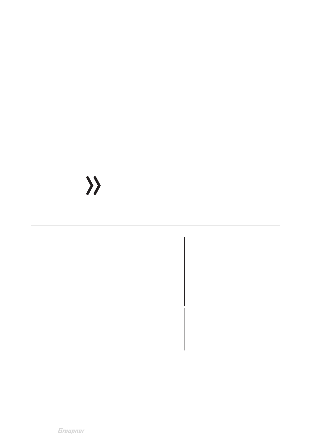
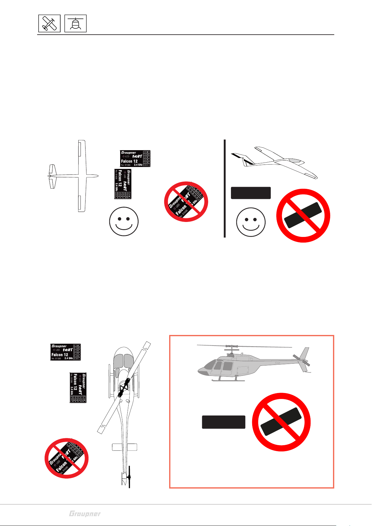
Fixed-wing model
The receiver must be aligned at right angles to the model on the
receiver platform.
The lower surface of the receiver must always be parallel to one of
the model sides.
Prior to installation, remove the sticker on the back of the receiver.
We recommend using double-sided tape No.: S8376 for Gr-18 to fix
the receiver in place. Also the so-called mirror adhesive tape is suitable.
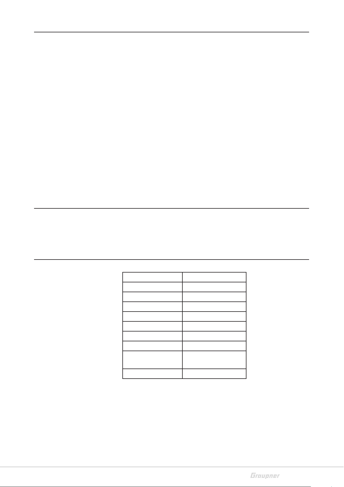
Helicopter model
OK
The receiver must be aligned at right angles to the helicopter on the
receiver platform. Prior to installation, remove the sticker on the
back of the receiver. We recommend using double-sided tape (No.
S8376 for Gr-18) to fix the receiver in place. The receiver must be
connected to a stable power supply with at least two power cables.
Comply with the maximum power consumption permitted by the
servos. All connections can be used for this purpose.
OK
8 / 36
This installaon posion is at the moment not yet relevant,
but in case of later use of the accelerometers (through so-
ware update) it will be important!
S1035_Falcon_12_jh_V1
Page 9
Binding
The binding is only possible if, since the switch-on of the receiver, it
has not been bound to any transmitter (red LED on).
If you want to bind the receiver to a new model memory, proceed as
follows:
Switch off the RF module in the transmitter’s “Model base set-
tings” (see transmitter’s manual)
Distance between transmitter and receiver, minimum 1 meter
Switch the receiver on (red LED on), wait about 15 seconds until
the red LED blinks, the receiver is now in binding mode
Start the binding in the transmitter’s “Model base settings”
menu
If the red LED of the receiver switches off within about 15 sec-
onds, the binding process has been concluded successfully. Your
transmitter/receiver combination is now ready for use.
If the red LED is still blinking, the binding has not been success-
ful. In this case please repeat the entire procedure.
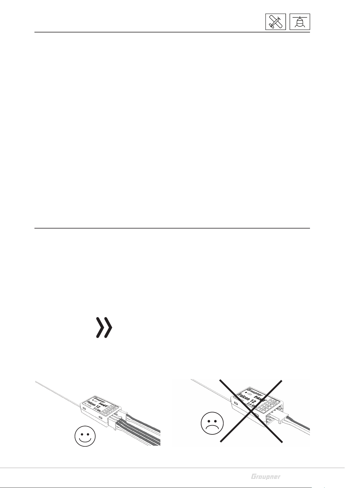
Interfaces
Connect the servos to the row of sockets on one end of the receiver.
The connectors are reverse polarity protected: note the small chamfers on the sides. Never use force – the connectors should engage
easily. The polarity is also printed on the receiver; the negative wire
(-) is brown, the positive (+) red and the signal orange. The servo
sockets of Graupner-HoTT 2.4 receivers are numbered sequentially.
The socket for channel 5 can also be programmed to deliver a (digital) sum signal (see receiver settings section).
Attention
Never connect a battery with voltage higher than 8,4V directly to
the receiver! The receiver and the connected servos would be
destroyed.
S1035_Falcon_12_jh_V1
9 / 36
Page 10

Power supply
The receiver does not feature specific sockets for connecting the
battery. We recommend that you connect the power supply to the
socket(s) close to the servos already connected to the receiver. If you
wish to connect multiple separate batteries, the batteries must be
of the same nominal voltage and capacity. Never connect different
battery types or batteries with strongly different charges since this
can cause an effect similar to a short circuit. In such cases for safety
reasons, insert voltage stabilizing elements such as PRX-5A (No.
4136) receiver power supplies between the batteries and receiver.
Programming the receiver settings
The receiver can be programmed with a suitable HoTT transmitter
or in connection with the SMART-BOX.
Receiver settings menu
RECEIVER 2.0 <
>LANGUAGE: English
Model type: HELI
ALARM VOLT 3,8V
ALARM TEMP: 70°C
CYCLE: 20ms
SUMD at C5: No
C5: Sensor
The receiver setup menu appears in the “Telemetry“ menu under
SETTINGS / DISPLAYS or if you are using a SMART-BOX under SETTING & DATAVIEW. How to access this menu is described in the operating instructions supplied with your transmitter or Smart-Box.
Model type
Setting "HELI" or "Fixed-wing". The following specific setting menus
will appear depending on the model type selected. Factory reset for
heli settings: Switch from heli to fixed-wing then disconnect the
power supply and reconnect it.
Then switch from fixed-wing to heli, disconnect the power supply
and reconnect it.
Low voltage warning (ALARM VOLT)
If the receiver voltage or the external voltage at channel 5 falls below
the set value, a low-voltage warning is generated by the transmitter's RF module in the form of a "general alarm tone" (regular beeping at a rate of approx. one beep per second) or the "receiver voltage" speech output message.
Temperature warning (ALARM TEMP)
If the receiver temperature exceeds the set temperature, a warning
is generated by the transmitter’s RF module in the form of a "general
alarm tone" (regular beeping at a rate of approx. one beep per second) or the "receiver temperature" speech output message.
10 / 36
S1035_Falcon_12_jh_V1
Page 11
Cycle time (CYCLE)
If your system is used exclusively with digital servos, you can set a
cycle time (frame rate) of 10 ms. If your system includes some or
uses exclusively analogue servos, you should always select 20 ms, as
many analogue servos cannot process the higher frame rate and
may respond by "jittering" or "growling".
SUMD (Sum signal) at channel 5
If you activate the digital sum signal at channel 5, a sum signal containing 8 channels is present at this socket, instead of a servo signal.
The HoTT receiver configured as SUMD constantly generates a digital sum signal from 8 control signals from the transmitter and makes
this signal available at the specified servo socket, which is receiver-specific. This type of signal was being used by some of the newest
flybarless systems and power supplies.
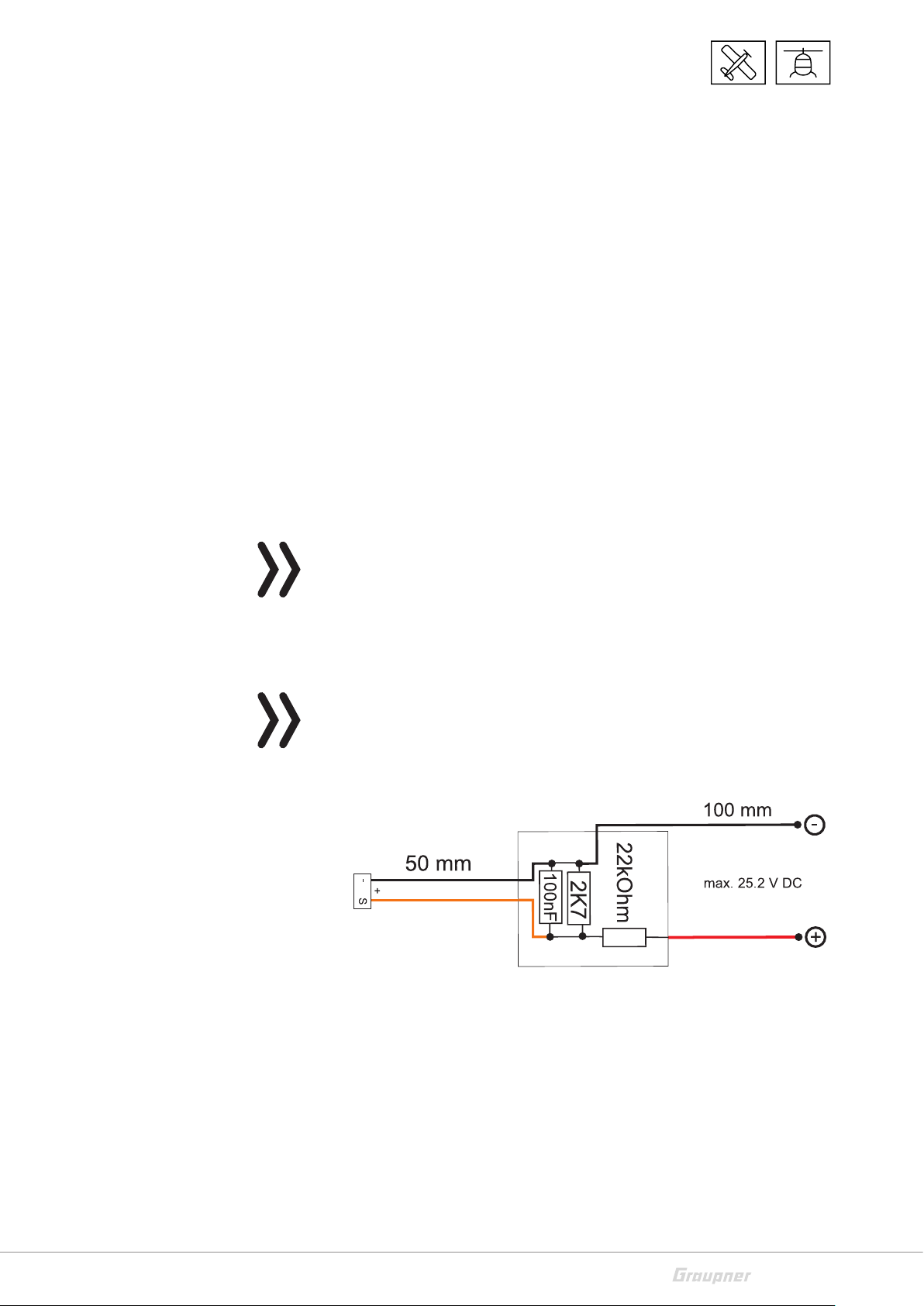
Channel 5 (C5)
This socket allows you to use either for telemetry "Sensor" or for an
extra channel servo 5 "Servo" or or for measuring the voltage "Voltage".
Attention! It is only possible one function at the same time!
Only through the unit described in the introduction it is possible to
measure a voltage up to max. 25.5 V DC. This voltage will be shown
in the display of the transmitter instead the receiver voltage. This
way it is possible to monitor the main battery voltage without using
external sensors.
Note
If the voltage measurement is active, the following described switch
(see sketch) must be used to measure a maximal voltage of 25.5 V
through this output. Never connect a battery to this telemetry port
without this switch!
<- Channel 9
This voltage distributor is included in the ESCs S3082 and S3083.
S1035_Falcon_12_jh_V1
11 / 36
Page 12

Programming a fixed-wing model
Free mixers
Note
If you wish to use the gyros, you must always set the tail type to
‘normal’ in the transmitter’s model type menu.
FREE MIXER < >
>MIXER: 1
FROM CHANNEL: 1
>TO CHANNEL: 6
>TRIM: +0%
TRV - : +100%
TRV + : +100%
If your model is a delta, features a V-tail, or has two elevator servos,
you must use the receiver mixer - not the transmitter mixer - to control these control surfaces, since the gyro stabilization system will
have no effect on these servos otherwise.
The four receiver mixers work ‘downstream’ of the gyros.
If you have already programmed mixer functions in the “Wing mixers” or “Free mixers” menu of your HoTT transmitter, you must
ensure that those mixers do not overlap with those available in this
menu!
Mixer
Up to four mixers can be contemporaneously programmed . You can
switch between Mixer 1, Mixer 2, … and mixer 4 in the “Mixer” line.
The following settings only affect the mixer selected in this line.
Programming examples
FREE MIXER < >
>MIXER: 1
FROM CHANNEL: 3
>TO CHNNEL: 4
>TRIM: +0%
TRV - : +100%
TRV + : +100%
From channel
The signal source (or source channel) is mixed in to the target channel (TO CHANNEL) with a programmable amount. The method of
setting up the values is analogous to the “Free mixers” menu in HoTT
transmitters.
To channel
TO CHANNEL: part of the source channel signal (FROM CHANNEL) is
mixed into the target channel (TO CHANNEL). The mixer ratio is
determined by the percentage values entered in the “TRAVEL-” and
“TRAVEL+” lines. Select "0" if you do not want to activate any mixer.
Mixer ratio (TRAVEL-/+): in these two lines you can define the mixer
ratio in relation to the source channel (FROM CHANNEL); the value
is set separately for both directions.
V-tail with rudder differential
FREE MIXER < >
>MIXER: 2
FROM CHANNEL: 4
>TO CHANNEL: 3
>TRIM: +0%
TRV - : -60%
TRV + : +100%
FREE MIXER < >
>MIXER: 3
FROM CHANNEL 4
>TO CHNNEL: 4
>TRIM: +0%
TRV - : +100%
TRV + : +60%
12 / 36
Differential is not normally necessary with this tail type. Mixer 3 is
not required if you do not need rudder differential, and TRAVEL for
mixer 2 must then be set to -100%.
Alternatively you may prefer to carry out the programming using the
transmitter menu.
S1035_Falcon_12_jh_V1
Page 13

A ‘Rudder / elevator’ mixer can be set up at the transmitter instead
of ‘Free mixer 3’ at the receiver; the mixer should be set up asymmetrically, e.g. +30%, -30%. This option frees up one mixer at the
receiver.
Delta with aileron differential (1 aileron)
FREE MIXER < >
>MIXER: 1
FROM CHANNEL: 2
>TO CHANNEL: 3
>TRIM: +0%
TRV - : +100%
TRV + : +60%
FREE MIXER < >
>MIXER: 2
FROM CHANNEL: 3
>TO CHANNEL: 2
>TRIM: +0%
TRV - : -100%
TRV + : -100%
FREE MIXER < >
>MIXER: 3
FROM CHANNEL: 2
>TO CHANNEL: 2
>TRIM: +0%
TRV - : +60%
TRV + : +100%
In this example aileron differential is set to 40%. Alternatively you
may prefer to carry out the programming using the transmitter
menu. A ‘Aileron -> elevator’ mixer can be set up at the transmitter
instead of ‘Free mixer 3’ at the receiver; the mixer should be set up
asymmetrically, e.g. +30%, -30%. This option frees up one mixer at
the receiver.
Two elevator servos
(channel 6 for the second elevator servo)
FREE MIXER < >
>MIXER: 1
FROM CHANNEL: 3
>TO CHANNEL: 6
>TRIM: +0%
TRV - : +100%
TRV + : +100%
Programming examples
Programming examples
Only for transmitters without a butterfly (crow) mixer
If a butterfly (crow) mixer is required, you will not be able to use one
of the two functions ‘differential’ or ‘landing flap’ adjustment, as 2
mixers are needed for this.
FREE MIXER < >
>MIXER: 1
FROM CHANNEL: 1
>TO CHANNEL: 2
>TRIM: +0%
TRV - : +100%
TRV + : +100%
FREE MIXER < >
>MIXER: 1
FROM CHANNEL: 1
>TO CHANNEL: 2
>TRIM: +0%
TRV - : +100%
TRV + : +100%
FREE MIXER < >
>MIXER: 2
FROM CHANNEL: 1
>TO CHANNEL: 5
>TRIM: +0%
TRV - : -100%
TRV + : -100%
FREE MIXER < >
>MIXER: 2
FROM CHANNEL: 1
>TO CHANNEL: 3
>TRIM: +0%
TRV - : -100%
TRV + : -100%
S1035_Falcon_12_jh_V1
13 / 36
Page 14

Gyro assignment
Axis assignment < >
>AILERON SERVOS: 2
DO SETUP: yes
AILE: (right) +2
ELEV:(push) +0
RUDD:(right) +0
Axis assignment < >
>AILERON SERVOS: 2
DO SETUP: No
AILE: (right) +2
ELEV:(push) +1
RUDD:(right) -3
Aileron servos:
You should enter the value 2 in this line if your model has two aileron servos. In this case the gyro for channel (servo) 2 also acts on
servo 5. If the ailerons are also used as flaperons or speedbrakes,
gyro suppression is based on the sum of both channels.
Note
The servo reverse setting must be the same for both aileron servos,
i.e. either both ‘normal’ or both ‘reverse’. If this is not possible, on
no account should you reverse one servo in the transmitter menu.
The only option is to re-install it in the model by turning it round
physically.
However, if your model is fitted with programmable servos (e.g.
Graupner DES, HVS or HBS types - see the instructions for the update
program ‘Firmware_Upgrade_grStudio - then it is possible to
reverse the direction of rotation at the servo itself.
Please read the installation notes on page 8 of these instructions.
The first step is to define the three gyro axes and the orientation of
the receiver. This is accomplished by switching on the transmitter
and model, and selecting ‘DO SETUP: yes’ in the receiver’s ‘Gyro settings’ menu.
Now move the stick for any control surface to full travel (in the
servo display at least 25%) in the indicated direction; in the following example we use the aileron channel.
The detected axis (aileron) is highlighted (black background). (In
the receiver’s default state the value for all axes is shown as ‘+0’;
the axes can also be set manually to ‘+0’. 0 = inactive)
Now turn the model through at least 45° in the direction corre-
sponding to the stick movement. For example, if you moved the
aileron stick to the left, you must simulate a left turn with the
model -> move the left wing down through at least 45°.
This process defines the one axis and direction; now you must
repeat the procedure for the other two axes.
The gyro axis 1, 2 or 3 is now displayed in the ‘Aileron / Elevator
/ Rudder’ display; a negative prefix will appear if servo reverse is
activated.
Once all three axes are defined, the display automatically reverts
to ‘New setting: no’.
14 / 36
S1035_Falcon_12_jh_V1
Page 15

Elevator
!
CAUTION
Check that all the gyros are
working in the correct
direction!
Move the model in all axes
directions. Check the movements and travels.
Now check the control
surface deflections - see
diagrams below.
You must not fly the model
before doing this: crash
hazard!
Movement of the model Control surface action (tail view)
Rudder
Movement of the model Control surface action (tail view)
Aileron
Movement of the model Control surface action (tail view)
S1035_Falcon_12_jh_V1
15 / 36
Page 16

Note
Before you start entering settings for a new model, it is essential to
select the number of aileron servos in the Aileron servos menu
point, and to define the gyro axes and orientation in the New settings menu point.
Programming the regulation
Gyro setting display
GYRO SETTINGS< >
MODE AIL/ELE (2) C H7
MODE RUDD (2)CH7
>Aileron: 0
>Elevator: 0
Rudder : 0
Factor : (44%)C10
MODE
In this point you can select the gyro correction mode (0-3):
0 - no gyro correction
1 - normal gyro correction (P and D parameter)
2 - heading lock mode (I parameter) with suppression
(Outside the suppression area the gyro control is active, in stick
center position acts the heading lock)
3 - Rate mode
(Heading lock acts in stick center position through the entire area)
Note
In Heading lock mode the servos are moved to the center position
if the factor is set to 0%.
Mode switching
The mode can be set separately for AILE/ELEV and RUDD. The mode
can be set permanently or it can be switched through an assigned
channel. Program the selected channel in your transmitter with a
switch, the following positions switch the related mode:
Mode 0 - 100%
Mode 1 - 50%
Mode 2 0%
Mode 3 ≥ 50%
Preparation step by step:
1. Trim the model with the gyro correction off
2. Switch the receiver off and on to save the values as standard
3. Activate the gyro correction
4. The phase trim should not be used!
5. Set the factor for gyro correction, eventually check the values for
the single control surfaces
16 / 36
S1035_Falcon_12_jh_V1
Page 17

Note
If the model is too agile in mode 3, it is then recommended to set
in the transmitter DUAL RATE and/or EXPO for this mode. Thus the
model will react in a more docile way. In the Rate mode the model
tries to reach the controlled rate. Also in mode 2 EXPO can be useful.
Aileron/elevator/rudder:
Shows the programmable factors for the corresponding control surface.
The gyro correction can also be disabled by setting the value to
"OFF". Do not exceed 4 - 5 as maximum value for the normal flight
phase, 2 - 3 for speed, 3 - 6 for landing. The maximum value of 10
should be reserved for torque-rolls only.
Factor (general sensitivity)
Setting this value the 3 parameters will be influenced contemporaneously.
General sensitivity for all gyros, action grade settable through a controller between 0 and 200%
Move the cursor to the Factor line. Move the cursor to reorder the
factor for aileron, elevator and rudder by using a proportional control (adjustment range up to 200%; channel value -100% means a
factor of 0%, channel value 0% means 100%, and +100% means
200%). This makes it a very easy matter to match the gyro’s corrective effect to the model’s airspeed. In particular, higher gyro gain can
be used for the landing approach - without the need to switch flight
phases.
Once you have found the optimum settings, you can set up a transmitter switch to control the gyro, i.e. for switching between gain settings. For example, you could assign a 3 position switch to “Factor”,
and then use it to switch the values between 0% and 100% (OFF) so
as 200%. In the transmitter the servo display for this 3 functions
switch must indicate -100, 0 and +100%.
Note
The OFF value means a gyro action of 100%!
Good to know!
The standard factor should cause the gyros to correct the model’s
attitude quickly when it is upset by an outside influence. Without
causing oscillation, but in practice the optimum values for a particular model can only be found by flight-testing. If the model shows little or no automatic stabilization with the default settings, the value
should be raised; on the other hand. If the model oscillates (wavelike movements in flight), the value should be reduced.
S1035_Falcon_12_jh_V1
Some transmitters allow the corrective factors to be altered during
a flight using the proportional controls, whereas others allow fixed
values only.
17 / 36
Page 18

Flight phase specific settings
It is possible to use a channel to control the factor value by setting
up flight phase specific transmitter control settings, but only with
some transmitters; please see the instructions supplied with your
transmitter and refer to the “Transmitter control settings” and “Flight
phase settings”.
Programming the axes sensitivity
GYRO SETTINGS< >
MODE AIL/ELE (2) C H7
MODE RUDD (2)CH7
>Aileron: (2)C9
>Elevator: (3)K8
Rudder : 6
Factor : (44%)C10
Programming through transmitter with proportional controls
If your HoTT transmitter is equipped with proportional controls, it is
also possible to adjust the value for each axis during a flight: what
you might call ‘flying the settings’. You need to assign proportional
controls to any channel in the range 5 to 16 (in this example channel
9); now you can alter the value using these controls. The current
value is shown in brackets.
Procedure, using the ailerons as an example: step by step:
1. Move the cursor to the appropriate line, in this case “Ail” for aileron.
2. Press the SET button to activate the "Channel" field.
3. Select the appropriate channel and save the setting with pressing the SET button again
4. Move the related proportional control to change the value (range
between 0 and 10, where 0 means no gyro correction for the
related axe).
5. This value can also be changed by pushing the left or the right
button. This frees up the channel previously occupied by the proportional control, So that it can be used for some other purpose,
e.g. for elevator or rudder.
GYRO SETTINGS< >
MODE AIL/ELE (2) C H7
MODE RUDD (2)CH7
>Aileron: 2
>Elevator: 4
Rudder : 6
Factor : Off
6. Move on to elevator and / or rudder, and select the channel and
value (you can either select the same channel, in order to alter
all the axes simultaneously, or different channels, allowing you
to program the axes individually).
7. Now test-fly your model and fine-tune the values one by one
until your preferred stabilising effect is achieved without the
model oscillating.
8. It may be sensible or easier to activate the gyro for one axis only
at first, and then to establish the optimum setting for that axis,
rather than for several axes simultaneously.
Programming by transmitter without proportional controls
1. Select by mode "0"; this function is only possible in case of transmitters with proportional controls.
2. Move the cursor to the appropriate line, in this case “Ail” for aileron.
3. Press the SET button to activate the input field. Select the appropriate value (1-10 or OFF) and save the setting with pressing the
SET button again.
18 / 36
S1035_Falcon_12_jh_V1
Page 19

Initialization of the gyro
4. First select a low value (see value section for starting points) and
carry out a test-flight. If gyro stabilization is not sufficiently pronounced, increase the value step by step until the level of correction is as required; if the model already oscillates, reduce the
value step by step.
5. Move on to "elevator" or "rudder" and select the desired value
(or OFF).
6. Leave the settings for “Factor” to OFF.
7. Activate the gyro for one axis only at first, and then to establish
the optimum setting for that axis, rather than for several axes
simultaneously.
Once the model has been switched on, the gyro immediately
becomes active but still needs to be initialized. To initialize the gyro,
keep your model still when you switch it on. After approx. 2 seconds
in still position, the ailerons move briefly in both directions. These
"wiggles" indicates that initialization has been successful and that
calibration is complete. Only now the model can be moved again.
Al the sticks must be left in the central position!
Note
During the initialization the neutral position will be detected, for
this reason it is very important that the model is not moved during
the activation!
In the same way during the gyro initialization also the central position of each control channel is saved. By gyro suppression the gyro
correction is reduced with increasing control deflection, at +/- 100%
of the gyro is deactivated.
Adjust servolimit for channels
SERVOLIMIT <
> 1: -150% +150% SEL
2: -150% +150% SEL
3: -150% +150% SEL
4: -150% +150% SEL
5: -150% +150% SEL
6: -150% +150% SEL
7: -150% +150% SEL
SERVOLIMIT <
> 1: -150% +83% STO
2: -150% +150% SEL
3: -150% +150% SEL
4: -150% +150% SEL
5: -150% +150% SEL
6: -150% +150% SEL
7: -150% +150% SEL
+83% STO
In this menu, you can limit the servo travel for all channels. Limit the
servo travel to the maximum possible deflection, so that the servos
can not run in the stop in the gyro operation. Move the cursor to the
desired line (by further downward move of the cursor will be displayed further channels), here “1” for channel 1 Pressing the SET
button is pressed the “SEL” field in “STO”.
Now move the stick of channel 1 in the desired direction and position, while the corresponding percentage display is shown inverted.
Now press the SET button again and the set value is displayed and
stored. Go through the procedure for the other channels.
S1035_Falcon_12_jh_V1
19 / 36
Page 20

Programming a helicopter model
Preparing the helicopter
Set all servos to neutral; the arms must be at right angles and the
swashplate must be in the neutral position (perpendicular to the
main rotor axis). The swashplate pushrods must be the same length.
Transmitter presettings
Select the free/deleted model memory and activate the helicopter
model. Set the pitch front/back according to your personal preferences and do not change it anymore.
All trims must be set to 0 (Servo display 0%) and must not be altered
in flight under any circumstances. If possible, trims should therefore
be deactivated in the transmitter (set the trim steps to 0).
• Activate or retain the servo for swashplate type 1 (the swashplate mixer is implemented in the FBL system of the receiver).
• The settings for the servo travel and direction remain at first to
standard, 100% and not reversed.
• Do not connect the tail servo if it does not have a mid-point of
1.5 ms (standard).
• Swashplate servo arrangement at 120/135/140°:
• front left = 1, front right = 2, back =3
2
• If the swash plate is turned of 180° and the nick servo is forward,
• Bind the receiver to the transmitter.
Initializing the gyro (helicopter)
Once the model has been switched on, the gyro immediately
becomes active but still needs to be initialized. To initialize the gyro,
keep your model still when you switch it on. The calibration process
can only be performed when the receiver is absolutely still. After
approx. 3 seconds in the idle position, the swashplate moves briefly
three times. These "wiggles" signal that initialization has been successful and that calibration is complete. Always wait until the calibration process has finished before starting to fly the model.
3
1
the connection sequence does not change. The left roll servo is
always 1.
20 / 36
S1035_Falcon_12_jh_V1
Page 21

Basic settings
Procedure
1. Once the transmitter and helicopter have successfully been prepared, call up the Telemetry menu in the transmitter (see transmitter instructions).
2. Set in the receiver the model type "Hely" (see section "Receiver
settings"). Then change to the menu "Base setup contr.".
3. Scroll past the swashplate/tail setup menus; these will be used
later on.
4. You must work through each item of this menu in order
from top to bottom:
Base setup controller
BASE SETUP CONTR.<v>
>Rotating dir right
Swp Type 120 deg.
Swp Frequency 200Hz
Swp direction +0
Swp Nick Trim +0
Swp Roll Trim +0
Swp Pitch Trim +0
Swp travel 8d +80
Collective_B +80
Cyclic max +80
Swp rotate +0
Tail servo 1.5ms
Tail frequency 333Hz
Tail mid +0
Tail limit B +50
Logging +3
Expertmode No
When a value is activated in the basic setting control, the gyro control and partly the control are deactivated! Therefore, settings must
not be carried out in the air, but must be carried out on the ground
without speed!
Rotation direction
Here you can set the direction of the rotor rotation, seen from above
the helicopter. Right or left
Swp type
Swashplate type: select the correct swashplate type. 90°, 120°, 135°,
140°.
S1035_Falcon_12_jh_V1
Default setting 120°
21 / 36
Page 22

Swp frequency
Swp frequency: frequency for the swashplate servos
50-200, default setting: 200 Hz
Warning: Analogue servos may only be operated at 50 Hz. If they are
not, the servos will be destroyed. Many digital servos can be operated at a higher frequency. (Use at your own risk). This allows the
model to be controlled more quickly. With HBS servos, we recommend setting the frequency to 200 Hz.
Swp direction
0-3, default setting: 0
Here, a fixed servo-combination of the Swp servos is selected, in
which the Swp does not tip during "pitching". (pitch direction is set
under C1 in the transmitter's servo menu with servo reverse, if
required).
Now check the direction of rotation of the swash plate for pitch, roll
and nick. If one of the control functions is reversed, the servo reversal must be performed as follows in the transmitter's servo settings:
Reverse for pitch = C1, for roll = C2 and for nick = C3.
Elev trim, Aile trim and Collective trim
-100 - +100, default setting: 0
The swashplate must be aligned as far as possible at right angles to
the main rotor axis and with 0° pitch. By activating one of these 3
values, the gyro control switches off and the servos move into their
neutral position. After that, the swash plate can be aligned optimally
with Elev trim, Aile trim and Collective trim. A perfect setting is
achieved when the rotor plane does not move in flight when the
pirouettes are performed.
Swp cyclic travel 8
50-125, default setting: +80
Set the Swp cyclic travel 8° if the menu value is activated so that the
rotor blade located above the tail tube is as accurate as 8° by full rollover stroke. To do this, the field must be selected (highlighted field)
so that the swashplate can be controlled and adjusted in direct mode
when gyro gain is switched off. This is the only mode in which the
travel can be set correctly.
It is very important that the travel is set correctly. It plays a major role
in terms of acquiring the correct gyro gain.
22 / 36
S1035_Falcon_12_jh_V1
Page 23

Collective_A/B
50-120, default setting: 80
It is selected automatically based on the pitch stick travel on the
transmitter. Use the pitch gauge to measure the required pitch travel
when the full commands are applied (+-100%) and set it in this menu.
All of the other settings can be made later on the transmitter for the
pitch curves in the respective flying phase.
Swp limit
50-200, default setting: +80
Swashplate limit. The swashplate limit must be set so that it is not
possible for a servo to reach its mechanical limits, while ensuring
that the servo's travel is as large as possible. No humming should
come from any of the servos when full travel commands are applied.
Swp rotate
-90-90, default setting: 0
"Swp rotate": a virtual Swp rotation (in degrees) can be set here (for
certain systems with several blades). Normally for rotor heads with
up to a 3 bladed no rotation is necessary.
The Swp (swashplate) is now fully set up and you can move on to the
tail:
Tail servo
Default setting: 1.5 ms
"Tail servo": select the correct mid-point for your tail servo here.
Mid pulse: 1,5ms, 760μs or 960µs.
Default setting: 1.5 ms. 1.5 ms is generally the default setting for tail
servos. Narrowband servos (generally special tail rotor servos) may
however require a different mid pulse width. You must locate this
value in the servo manual and set it correctly. If a value has not been
specified, it is probably a standard servo set at 1.5 ms. If you have a
DES, HVS or HBS servo, this value can sometimes be programmed.
However, we recommend sticking with the default setting.
The control direction of the tail rotor can now be checked. If it is
reversed, the servo reversal of channel 4 must be performed in the
transmitter's servo settings.
Tail frequency
"Tail frequency": the tail frequency can be set to between 50 and
333 Hz.
S1035_Falcon_12_jh_V1
Default setting: 333 Hz
Warning: Analogue servos may only be operated at 50 Hz. If they
are not, the servos will be destroyed.
Many digital servos can be operated at a higher frequency (use at
your own risk).
23 / 36
Page 24

This allows the model to be controlled more quickly. With HBS servos, we recommend setting the frequency to 333 Hz.
Tail center
-100 - +100, default setting: 0
If the value "Value tail center" (inverted field) is activated, the tail
servo moves to the neutral position. The tail servo arm should be at
a 90-degree angle to the tail linkage pushrod.
The fine trim is then adjusted based on the mid-point of the tail.
When the servo is set to neutral, the tail rotor should have a pitch
angle of approx. 2 to 3° against the torque. Check whether the control direction is correct, if not then reverse the servo channel of C4
in the transmitter.
Tail limit A/B
50-200, default setting: +50
Limits the tail servo travel. Select the direction by moving the tail
stick to its endpoint. The display shows the values for A and B for
both endpoints, which are set separately. It must be set so that it
does not reach its mechanical limits but so that the full travel can be
used. Values that are suitable in terms of aerodynamics should be
selected here. If the travel is too large, this may cause the servo to
stall.
Logging
Default setting: +3
logs the corresponding servo to SD card of the transmitter for later
evaluation and error analysis with active flight timer.
0 = no logging
1 = roll and nick logging
2 = roll logging
3 = nick logging
4 = tail logging
We recommend always logging at least one function.
Expertmode
"Expertmode" is set to "No" by default. Even experts should stick
with this setting when carrying out the first steps with the new system. There are much fewer options in the Swp and tail menu and
they should only switch to Expertmode and its additional options if
they need to and when they have got used to the system.
24 / 36
S1035_Falcon_12_jh_V1
Page 25

Axis assignment
DO SETUP
Axis assignment <
>DO SETUP: Yes
Roll (right): +2
>Nick (push) +0
>Tail: (right +0
Axis assignment <
>DO SETUP No
Roll (right): +2
Nick: (push): +1
>Tail (right): -3
DO SETUP: Yes/No
Assignment of the gyros and their operating direction.
If you have not already done so, you must now set the C1-4 servo
directions so that everything works correctly.
In the receiver's "Axis assign" menu, go to the "Setup" option and set
it to "Setup: Yes". Now assign the axes as follows:
On the transmitter, briefly set the roll command fully to the right; the
roll axis is highlighted. You will then have both hands free again to
operate the helicopter.
Roll the helicopter more than 45° to the right → the identified axis
with the required prefix is displayed, the field is no longer highlighted
and identification of this axis is complete
Now do the same for nick: on the transmitter, briefly set the nick
command so that it is fully forward.
Roll the helicopter more than 45° forwards; the axis is displayed, the
field is no longer highlighted and identification of this axis is complete
Finally complete the procedure for the tail: on the transmitter, briefly
set the tail command fully to the right
S1035_Falcon_12_jh_V1
Turn the helicopter so that the nose turns more than 45° to the right;
the axis is displayed, the field is no longer highlighted and identification of this axis is complete.
The assignment of the axis assignment automatically adjusts the pirouette optimization. If the tail servo direction is subsequently
changed, the axis assignment must be performed again.
The gyros and operating directions have now been assigned. Now
check to make sure that the operating directions are correct. See the
illustrations below.
25 / 36
Page 26

Checking nick
Tilt the helicopter so that its nose is facing downwards; the swashplate moves consequently backwards.
Incorrect! Right!
Checking roll
Tilt the helicopter to the right; the swashplate moves consequently
to the left.
Checking the tail direction of operation
This effect depends by the helicopter, the left-hand or the right-hand
rotator, as well as the side and the direction of rotation of the tail
rotor. Refer to the heli's instructions for this information.
If one of the directions of operation is wrong, you must repeat the
axis assignment process. As a result of the control, the servos no longer return to their zero position or move slower. This is not a mistake
and it will not be noticeable in the air, since then the regulation can
work freely.
Note
However, we strongly recommend flying your model first using the
settings without Expertmode. If the directions are changed on the
transmitter due to any modifications being made to the helicopter
(e.g. new servos) or if the receiver is installed in a different position,
the axis assignment procedure must be fully repeated.
Swashplate setting without Expertmode
SWASHPLATE ADJUST<v>
Swp sense (5)C9
Swp rate +100%
Expo Swp +1
Direct stick R +100
Direct stick N +100
SWP sensitivity
1-100, min or C5…C16
Default setting: 70
The "SWP sensitivity" row allows you to specify a sensitivity setting
either using the values 1 to 100 or by assigning a channel (C5 to C16)
with a proportional control, which is used to control the value.
Different settings can then be used through the HoTT transmitters
to adjust the sensitivity based on specific flight phases, eg through
the control settings or the "Gyro" in the hely mix menu.
If the values are too high:
The heli oscillates around the rotor shaft. In this case, the sensitivity
should then be reduced somewhat until vibration-free flies are possible in all flight situations.
If the values are too low:
Helicopter no longer hovers in a stable manner, susceptible to wind.
26 / 36
S1035_Falcon_12_jh_V1
Page 27

Swp rate
Servo travel
Control travel
Expo = –100%
50 -120, default setting 85
Sets the max. potential rate of rotation in Rate mode for roll and nick.
Expo Swp
0 -50, default setting 15
You can set here an exponential curve (0 - 50%) for the rate of roll
and nick. Low percentages result in a linear increase in the rate of
rotation. High percentages a strong curve, the heli then no longer
reacts so sensitive to the center of the stick. We recommend to use
the Expo in the GR18 or in the transmitter. When using the expo in
the transmitter, the value here must be set to 0, otherwise the two
Expo settings overlap.
Expo = +100%
Servo travel
Control travel
Direct stick R (Roll), Direct stick N (Nick)
20 -150, default setting +115
The direct stick setting allows you to set the direct response of the
helicopter to the pilot's commands. If the nick command stops
abruptly, the helicopter will oscillate if the value is set too high.
Swashplate setting with Expertmode
SWASHPLATE ADJUST<v>
>SWP sensitivity(5)K9
Swp rate +85
EXPO Swp +15
Direct stick R +125
Direct stick N +125
P swp +100
(See above for swashplate sensitivity menu item)
(See above for Rate and Expo menu item)
(See above for direct stick menu item)
P swp (proportional) swashplate
Swashplate P-factor
Expo = +50%
Servo travel
Control travel
I Swp +70
D Swp +25
Speedflight +20
Stop optimizer +6
Anti-ballooning +0
S1035_Falcon_12_jh_V1
40 - 125, default setting: +90
The P swashplate option is responsible for effecting a harder stop
with the swashplate. Higher values result in a faster stop. If the P values are too high, the helicopter and/or the swashplate will start to
"oscillate". In such cases, the value must be reduced again.
I swp (integral) swashplate
Swashplate I-factor
30 - 125, default setting: +85
27 / 36
Page 28

The I-factor ensures constant rolling/nicking. Start with low values
and only increase them until the roll and nick rates are constant.
D swp (differential)
D-factor for swashplate
0 - 70, default setting: +40
The D swp D-factor influences the how the swashplate is stopped.
If the helicopter bounces somewhat when nick is stopped, this
parameter should first be increased in small increments to test the
nick stop. If the optimization was unsuccessful, return to the factory
defaults and continue with the Stop Optimizer setting.
Swp dynamic
10 -100, default setting: 90
Higher dynamic values provide a more direct control feeling, lower
values result in a smoother control feel. If the values are too high,
the swashplate does not stop and it can overflow. If the values are
too low, the control behavior becomes softer.
Speedflight optimisation
10 - 40, default setting: +15
When the helicopter is flying quickly in a straight line, it should fly
precisely in one line/at one altitude and not in a wave form. If the
helicopter flies in a wave form, the value can be increased until the
helicopter flies straight. This parameter should generally not be
changed.
Stop optimizer
0 - 10, default setting: 0
The value 0 means that the default stop optimizer is activated. The
values 1-10 are provided for the individual adjustment of the
extended stop optimizer. If the value is too low, the helicopter jerks
up during the fast pitch stop. If the value is too high, the system can
oscillate or the stop can be executed in two stages.
Anti-ballooning
0 - 50, default setting: 0
During an extreme fast flight, the heli can suddenly rebound without
control inputs. This is due to physical factors and depends on the
rotational speed of the main rotor and the pitch angle of the rotor
blades (pitch).
28 / 36
Pilots who want to fly safely in this border area can also activate this
parameter.
The default value is "0", the compensation is switched off by default.
The "Anti-ballooning" parameter can be adapted to each heli individually.
S1035_Falcon_12_jh_V1
Page 29

If you want to use the Anti-ballooning compensation, start with the
Servo travel
Control travel
Expo = –100%
value "30". A reduction of the parameter eg to the value "25"
increases the "rearing" tendency. An increase to, for example, "35"
reduces the tendency but can also adversely affect the final speed.
You need to find an optimal compromise between safe flight behavior without rearing and maximum speed. For this, first start in 5 steps
and then make the fine tuning in 1 steps.
Tail rotor setting without Expertmode
TAIL ADJUST<v>
>Tail sensitiv. 65
Tail rate +85
EXPO tail +40
Tail sensitivity
1-100, min or C5…C16
Default setting: 65
The "Tail sensitiv." row allows you to specify a sensitivity setting
either using the values 1 to 100 or by assigning a channel (C5 to C16)
with a proportional control, which is used to control the value.
The max. tail sensitivity is first determined at the highest speed and
it should be flown individually for each speed. It can be increased
until the tail begins to swing up. Afterwards, the tail sensitivity has
to be reduced a little, until in all flight positions no swinging of the
tail is recognizable anymore.
Different settings can then be used through the HoTT transmitters
to adjust the sensitivity based on specific flight phases, eg through
the control settings or the "Gyro" in the hely mix menu.
Tail rate
50 -120, default setting: 85
Sets the max. potential rate of rotation in Rate mode for the tail.
Expo = +100%
Servo travel
Control travel
S1035_Falcon_12_jh_V1
Servo travel
Expo = +50%
Control travel
Tail Expo
0 -50, default setting: 40
You can set here an exponential curve (0 - 50%) for the rate of the
tail. Low percentages result in a linear increase in the rate of rotation. High percentages produce a strong curve, the heli then no longer reacts so sensitive to the center of the stick. The Expo setting can
also be adjusted in a phase-related manner at the transmitter. But
avoid a overlapping of GR18 Expo and transmitter Expo.
29 / 36
Page 30

Tail rotor setting with Expertmode
(See above for tail sensitivity menu item)
P tail
Tail rotor adj.<v>
>Tail sensitiv.(5)C9
Tail rate +85
EXPO tail +40
P tail +80
I tail +70
D tail +15
Pitch->Heck +25
Swp-> Tail +4
Swp dynamic +65
Anti ballooning. No
Stop damp. R +5
Stop damp. L +5
Tail P-factor
40-125, default setting: +80
The P tail option is responsible for effecting a harder stop with the
tail. Higher values result in a faster stop. If the P values are too high,
the tail will start to "oscillate". In such cases, the value must be
reduced again.
I tail
Tail I-factor
20-100, default setting: +70
The I-factor ensures constant pirouetting. Start with low values and
only increase them until the pirouettes are constant. If the values are
too high, this will cause the tail to oscillate slowly.
D tail
Tail D-factor
0 - 50, default setting: +15
The tail D-factor influences how the tail is stopped. If the tail bounces
somewhat when the tail is stopped, this parameter should first be
increased in 5-degree increments to test the tail stop.
Pitch->tail Swp->tail
Pitch->tail Swp->tail
0- 80, default setting: +25 0-40, default setting: +4
Static torque compensation for pitch and cyclic.
These two functions work best when they are set together.
Pitch>tail: In the event of fast pitch pumping and swashplate movements, the tail should remain stable even when load is applied. If the
tail swings out briefly, the "Collect. torque" setting can be increased
until the tail stops.
On the ground, you can easily check whether the tail is working
against the torque.
Swp->tail is useful with slow-speed tail rotor with less tail power and
is then set to 1/3 of the value of pitch-> tail. With high speeds and
good rear power the value can be set to 0.
30 / 36
S1035_Falcon_12_jh_V1
Page 31

Tail dynamic
10 -100, default setting: 65
Higher dynamic values provide a more direct control feeling, lower
values result in a smoother control feel. If the values are too high,
the tail does not stop and it can overflow. If the values are too low,
the control behavior becomes softer.
Vibration damping
YES-NO, default setting: NO
The vibration damping automatically detects emerging vibrations at
the tail rotor, e.g. at extreme speed flights (wind flag effect) or strong
speed changes in some 3D maneuvers (over-speed) and prevents an
extremely strong swing-up. The tail rotor should be set free of vibrations without active vibration damping in 3D and normal flight situations, only with a solid basic setting it makes sense to activate the
vibration damping.
Stop damping R / Stop damping L
0 -20, default setting: 5
The rear stop parameter on the right and left optimizes the stop
behavior after a yaw movement. The tail should stop as quickly as
possible without moving back. Select the value so low that the tail
does not move back at when stopping. The higher the value, the
more the stop is dampened. Determine the value in steps of 1.
S1035_Falcon_12_jh_V1
31 / 36
Page 32

Firmware update
Updates to the receiver’s firmware are made via the output channel
5 / telemetry socket using a PC running Windows. You will also need
a USB interface, order No. 7168.6, and adapter lead, order No.
7168.6A or 7168.S, which are available separately.
The programs and files required can be found in the Download area
for the corresponding products at:
www.graupner.de
Connect the adapter lead to the USB interface No. 7168.6. The connectors are reverse polarity protected: note the small chamfers on
the sides. Never use force – the connectors should engage easily.
Connect the adapter lead to the receiver's telemetry socket. The
connectors are reverse polarity protected: note the small chamfers
on the sides. Never use force – the connectors should engage easily.
Starting the "Slowflyer/Gyro receiver update"
We recommend accessing the "Slowflyer/Gyro receiver update" program from the "Firmware_Up-grade_grStudio" program. Click on
the "Receiver Downloader" item under "Link" in the left function
menu. (Alternatively, select the "Micro Receiver Upgrade" under
"Menu").
It is also possible to start the associated application program directly.
By double-clicking on the file “micro_gyro_swloader.
exe”. You will find this .exe file in the "Graupner_ PC Software" folder
of the "HoTT_Software VX" package.
A program window will now appear in which you should first set the
"correct" COM port for the USB interface No. 7168.6 in the selection
window. (See following picture)
If you are not sure which port to use, check the COM port in the
"Select Port" window in the "Menu" of the "Firmware_Up-grade_
grStudio" and note down the COM port number for the "Silicon Labs
CP210x USB to UART Bridge" entry – in this case "COM03". (If you
select the wrong port, you will be alerted to this when you read out
the receiver data). Click on "File" to load the corresponding firmware
file named e.g. "GR12_33577_V_XX.bin" from the hard disc ("XX"
stands for the version number).
32 / 36
S1035_Falcon_12_jh_V1
Page 33

When the file has loaded, click on start...
... connect the receiver and switch it on.
The progress bar shows that the transfer is running normally. The
receiver LED lights up red during this process and flashes once the
transfer is completed.
Declaration of conformity
Please refer to the detailed update instructions for the item in question in the Download area at www.graupner.de.
S1035 - Falcon 12 HoTT 2.4 GHz 3 axis gyro receiver
Graupner/SJ declares that the product is conform to EU norms.
EN 301 489-1 V1.9.2 EN 301 489-17 V2.2.1
EN 300 328 V2.1.1
EN 60950-1+A11+A1+A12+A2:2013
EN 62311:2008
S1035_Falcon_12_jh_V1
33 / 36
Page 34

Notes on environmental protection
P
Disposal notes
This symbol on the product, user manual or packaging indicates that
this product must not be disposed of with other household waste at
the end of its life. It must be handed over to the applicable collection
point for the recycling of electrical and electronic equipment.
The materials are recyclable as marked. By recycling, material reusing or other forms of scrap usage you are making an important contribution to environmental protection.
Care and maintenance
Notes on care
The product does not need any maintenance, it works so as it is without any special care. In your own interests protect it from dust, dirt
and moisture.
Clean the product only with a dry cloth (do not use detergent!) lightly
rub.
Warranty
The Graupner/SJ, Henriettenstrassee 96, 73230 Kirchheim/Teck
grants from the date of purchase of this product for a period of 24
months. The warranty applies only to the material or operational
defects already existing when you purchased the item. Damage due
to wear, overloading, incorrect accessories or improper handling are
excluded from the guarantee. The legal rights and claims are not
affected by this guarantee. Please check exactly defects before a
claim or send the product, because we have to ask you to pay shipping costs if the item is free from defects.
The present construction or user manual is for informational purposes only and may be changed without prior notice. The current
version can be found on the Internet at www.graupner.de on the
relevant product page. In addition, the company Graupner/SJ has
no responsibility or liability for any errors or inaccuracies that may
appear in construction or operation manuals.
No liability can be accepted for printing errors.
34 / 36
S1035_Falcon_12_jh_V1
Page 35

FCC Statement
1. This device complies with Part 15 of the FCC Rules. Operation is subject to the following two conditions:
(1) This device may not cause harmful interference.
(2) This device must accept any interference received, including
interference that may cause undesired operation.
2. Changes or modifications not expressly approved by the party responsible for
compliance could void the users’ authority to operate the equipment.
3. To comply with FCC RF exposure compliance requirements, a separation distance of at least 20 cm must be maintained between the antenna of
this device and all persons.
4. This Transmitter must not be co-located or operating in conjunction with any other antenna or transmitter
FCC Caution
Note: This equipment has been tested and found to comply with the limits for a Class B digital device, pursuant to part 15 of the FCC Rules. These limits
are designed to provide reasonable protection against harmful interference in a residential installation. This equipment generates, uses and can radiate
radio frequency energy and, if not installed and used in accordance with the instructions, may cause harmful interference to radio communications.
However, there is no guarantee that interference will not occur in a particular installation. If this equipment does cause harmful interference to radio or
television reception, which can be determined by turning the equipment off and on, the user is encouraged to try to correct the interference by one or
more of the following measures:
• Reorient or relocate the receiving antenna.
• Increase the separation between the equipment and receiver.
• Connect the equipment into an outlet on a circuit different from that to which the receiver is connected.
• Consult the dealer or an experienced radio/TV technician for help.
IC Statement
Under Industry Canada regulations, this radio transmitter may only operate using an antenna of a type and maximum (or lesser) gain approved for the
transmitter by Industry Canada.
To reduce potential radio interference to other users, the antenna type and its gain should be so chosen that the equivalent isotropically radiated power
(e.i.r.p.) is not more than that necessary for successful communication.
Conformément à la réglementation d'Industrie Canada, le présent émetteur radio peut fonctionner avec une antenne d'un type et d'un gain maximal (ou
inférieur) approuvé pour
l'émetteur par Industrie Canada. Dans le but de réduire les risques de brouillage radioélectrique à l'intention des autres utilisateurs, il faut choisir le type
d'antenne et son gain de sorte que la puissance isotrope rayonnée équivalente (p.i.r.e.) ne dépasse pas l'intensité nécessaire à l'établissement d'une
communication satisfaisante.
This radio transmitter (identify the device by certification number, or model number if Category II) has been approved by Industry Canada to operate with
the antenna types listed below with the maximum permissible gain and required antenna impedance for each antenna type indicated. Antenna types not
included in this list, having a gain greater than the maximum gain indicated for that type, are strictly prohibited for use with this device.
Le présent émetteur radio (identifier le dispositif par son numéro de certification ou son
numéro de modèle s'il fait partie du matériel de catégorie I) a été approuvé par Industrie
Canada pour fonctionner avec les types d'antenne énumérés ci-dessous et ayant un gain admissible maximal et l'impédance requise pour chaque type
d'antenne. Les types d'antenne non inclus dans cette liste, ou dont le gain est supérieur au gain maximal indiqué, sont strictement interdits pour
l'exploitation de l'émetteur.
IC Caution
The minimum separation generally be used is at least 20 cm, even if the calculations indicate that the MPE distance would be lesser.
This device complies with Industry Canada licence-exempt RSS standard(s).
Operation is subject to the following two conditions:
(1) This device may not cause interference and (2) this device must accept any interference,including interference that may cause undesired operation of
the device.
Le présent appareil est conforme aux CNR d'Industrie Canada applicables aux appareils radio exempts de licence.L'exploitation est autorisée aux deux
conditions suivantes :
(1) l'appareil ne doit pas produire de brouillage, et (2) l'utilisateur de l'appareil doit accepter tout brouillage radioélectrique subi, même si le brouillage est
susceptible d'en compromettre le fonctionnement.
S1035_Falcon_12_jh_V1
35 / 36
Page 36

 Loading...