

Page 1
EN
Manual
Vector Unit / Vector Unit Extreme
2 channel HoTT 2,4 GHz receiver/servo/speed controller unit
No. 34002
No. 34003
C op yr i gh t © Gr a up n er / SJ Gm b H
Page 2

Page 3
Page 4

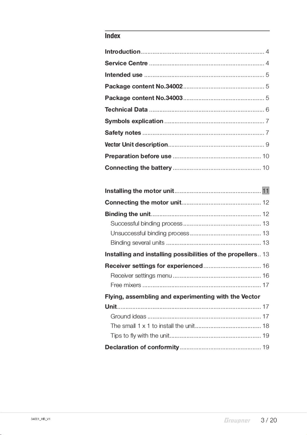
Introduction
�
Thank you very much for purchasing the Graupner Vector unit.
This manual is valid for all the units listed on the cover sheet. The
package content changes depending on the version.
Read this manual carefully to achieve the best results with your
Vector unit and first of all to safely control your models. If you
experience any trouble during operation, take the instructions to
help or ask your dealer or Graupner Service Centre.
Due to technical changes, the information may be changed in
this manual without prior notice. Keep updated by regularly
checking our own website, www.graupner.de to be always
updated with the products and firmware.
This product complies with national and European legal requirements.
To maintain this condition and to ensure safe operation, you must
read and follow this user manual and the safety notes before using
the product!
NOTE
This manual is part of that product. It contains important information
concerning operation and handling. Keep these instructions for future
reference and give it to third person in case you gave the product.
Service Centre
Graupner Central Service
Graupner/SJ GmbH
Henriettenstraße 96
D-73230 Kirchheim/Teck
Graupner USA
3941 Park Dr Suite 20-571
El Dorado Hills, CA 95762
Graupner in Internet For the service centers outside Germany please refer to our web
site www.graupner.de
Servicehotline
(+49) (0)7021/722-130
Monday - Thursday:
9:15 am - 4:00 pm
Friday:
9:15 am - 1:00 pm
service@graupner.de
Website: www.graupnerusa.com
Phone: +1 855-572-4746
Email:service@graupnerusa.com
Page 5

Intended use
Target group
This Vector unit may only be used for the purpose specified by
the manufacturer for operation of remote control models without
passengers. Any other type of use is impermissible and may
damage the system and cause significant property damage
and/or personal injury. No warranty or liability is therefore offered
for any improper use not covered by these provisions.
Read through this entire manual before you attempt to install or
use the transmitter.
Graupner/SJ constantly works on the development of all products; we reserve the right to change the item, its technology and
equipment.
The product is not a toy. It is not suitable for children under 14
years. The installation and operation of the unit must be performed by experienced modellers. If you do not have sufficient
knowledge about dealing with radio-controlled models, please
contact an experienced modeler or a model club.
Package content No.34002
Package content No.34003
Vector Core GRS 331
34001.4 Vector Motor CW
34001.30 Vector Propeller 46 mm
Manual
Vector Core GRS 331
34001.4 Vector Motor Extreme CW
34001.31 Vector Propeller 56 mm
Manual
34001_HB_V1
5 / 20
Page 6
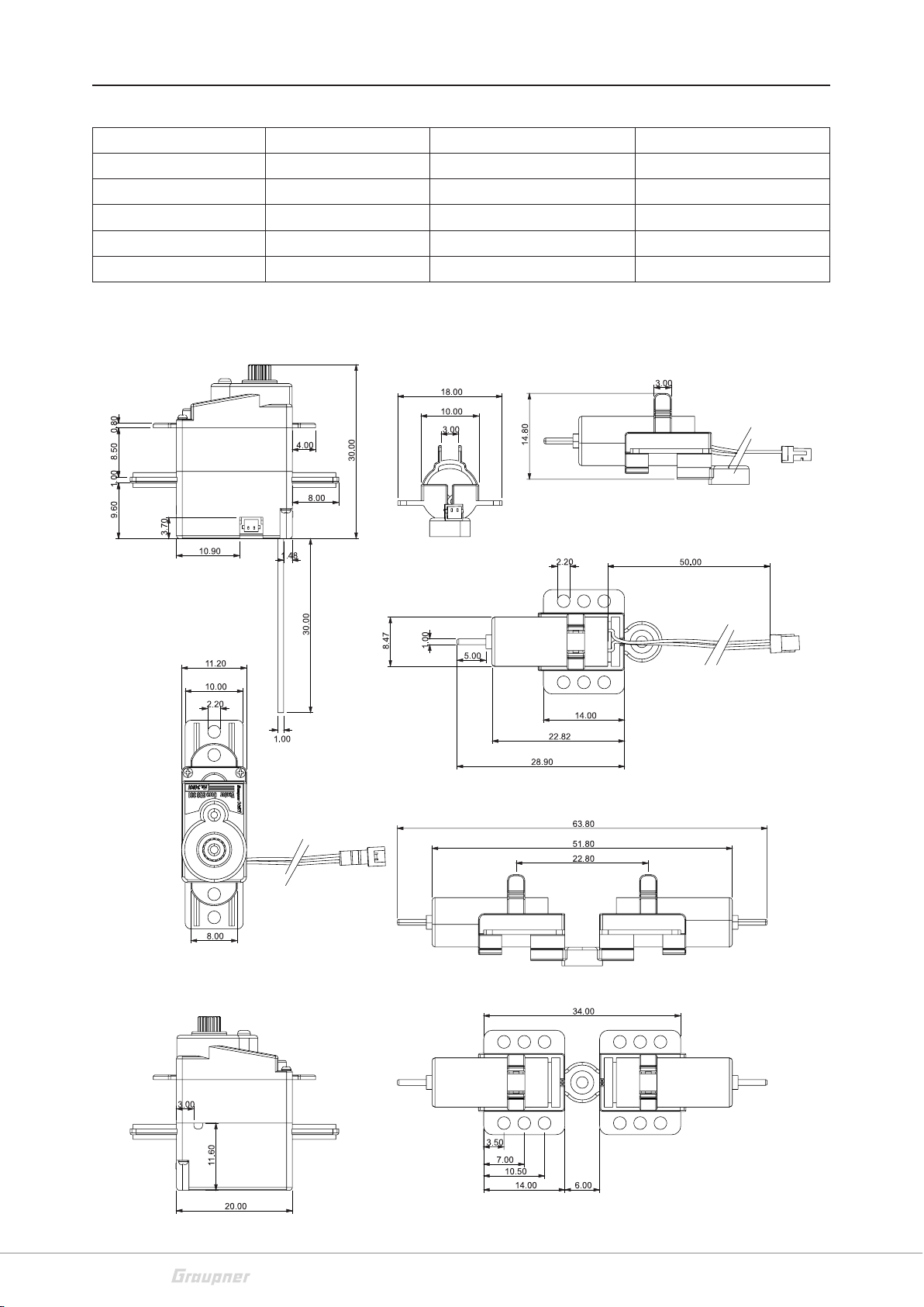
Technical Data
Frequency band 2,4 … 2,4835 GHz Motor unit single approx. 6,8 g
Modulation FHSS Motor unit double approx. 13,7 g
Temperature range -10 … +55 °C Current consumption max. 2A continuous current
Antenna Wire 30 mm Stall torque/3,7 V approx 5 Ncm
Operating voltage 3.0V ~ 4.2V Speed/3,7C approx. 0,06 sec./40°
Weight Vector Core approx. 6,6 g
6 / 20
34001_HB_V1
Page 7

Symbols explication
Safety notes
Always observe the information indicated by this warning sign.
!
Particularly those which are additionally marked with the CAUTION or WARNING. The signal word WARNING indicates the poten-
tial for serious injury, the signal word CAUTION indicates possibil-
ity of lighter injuries.
The signal word Note indicates potential malfunctions.
Attention indicates potential damages to objects.
This safety notes are intended to protect you and other people.
They are also used for safe handling the product. Therefore
please read this section very carefully before using the product!
Do not carelessly leave the packaging material lying around,
since it might become a dangerous toy for children.
Persons, including children, with reduced physical, sensory or
mental capabilities, or lack of experience or knowledge, or not
capable to assemble and use safely the Vector unit must not use
the Vector unit without supervision or instruction by a responsible person.
Inform yourself before flying your
model on which maximum
altitude you can fly in the uncon-
trolled airspace over the starting
position and do not exceed it.
Operation and use of radio-controlled models needs to be
learned! If you have never operated a model of this type before,
start carefully and make yourself familiar with the model's reactions to the remote control commands. Proceed responsibly.
First, always perform a range and function test on the ground
(to do so, hold your model tight), before you use your model.
Repeat the test with running motor and with short throttle bursts.
Before you start using the remote control model, you have to
check the further relevant laws and regulations. These laws you
must obey in every case. Pay attention to the possibly different
laws of the countries.
The insurance is mandatory for all kinds of model operation. If
you already have one, so please inform yourself if the operation
of the respective model is covered by your insurance. If this is
not the case, conclude a special liability insurance policy for
models. We recommend to provide the model with a label,
where are indicated the name, address, tel. n., E-mail and Insurance N.
34001_HB_V1
7 / 20
Page 8

So that the copter can be clearly assigned in the event of a
crash.
Due to safety and licensing reasons (CE), any unauthorized
reconstruction and/or modification of the product is prohibited.
Only use the components and spare parts that we recommend.
Always use matching, original Graupner plug-in connections of
the same design and material.
Make sure that all of the plug-in connections are tight. When disconnecting the plug-in connections, do not pull the cables.
Protect the Vector unit from dust, dirt, moisture and other foreign
parts. It must be protected from vibration as well as excessive
heat or cold. The models may only be operated remotely in normal outside temperatures such as from -10°C to +55°C.
Only operate all your HoTT components using the current software version.
If you have questions which cannot be answered by the operating manual, please contact us (contact information see page 3)
or another expert in the field.
WARNING
!
Safety notes during the use
Also while programming, make sure that a connected electric
motor cannot accidentally start. Injury risk by the turning propellers! Always remove the propellers when programming. Program always the motors stop switch on the transmitter. (See
transmitter manual)
Avoid shock and pressure. Check the Vector unit regularly for
damages to the housings and cables, specially after a crash of
the model. Damaged or wet electronic components, even if
re-dried, should no longer be used!
Never touch the turning propellers, this can cause injury
The propellers must be mounted securely, thrown parts can
cause serious injury.
Observe the safety notes of the required components.
Never fly against people or animals, risk of injury through the
propellers
8 / 20
34001_HB_V1
Page 9

Vector Unit description
11
6
12
11
13
2
10
12
6
9
11
6
10
10
12
3
13
1
14
6
7
8
5
1 Vector Core, Servo DES 131 with integrated receiver and speed controller
2 Battery connection cable
3 Drive gear to install a motor unit or a servo lever
4 Motor connection socket max. 2A continuous current
5 Receiver antenna
6 Fixture arms
7 + cable (red)
8 - cable (black)
9 Motor mount fixing screw, flat-head screw 1,2 x 3 mm
10 Motor mount
11 Motor
12 Propeller
13 Motor connection plug
14 Drive gear joint
4
34001_HB_V1
9 / 20
Page 10

Preparation before use
Connecting the battery
The Vector unit should only be powered by a 1 S LiPo battery
PowerPack No. 78101.1.
The input voltage of the drive battery is monitored during the
flight through the telemetry function of the HoTT transmitter.
If the voltage drops under 3.2 V, the warning alarm will be
activated in the HoTT transmitter. Stop immediately the use and
charge the drive battery!
To switch on the unit connect the drive battery to the battery
connection cable (2).
Use exclusively the batteries recommended by us.
The connectors are reverse polarity protected: note the small
chamfers on the sides. Never use force – the connectors should
engage easily.
Attention
If the connection system is connected and forced in the wrong
direction, then the connector of the battery connection cable will
be ruined.
Never connect a battery with voltage higher than 4,2 V DC to
the unit! The receiver and the servo would be destroyed.
Never connect a battery to the motor socket in the unit! The
receiver and the servo would be destroyed.
10 / 20
34001_HB_V1
Page 11

Page 12

Connecting the motor unit
Use exclusively the motor units recommended by us.
The connectors are reverse polarity protected: note the small
chamfers on the sides. Never use force – the connectors should
engage easily.
Attention
If the connection system is connected and forced in the wrong
direction, then the connector of the motor connection cable will
be ruined.
Never connect a battery with voltage higher than 4,2 V DC to
the motor unit! The motor will be damaged.
Binding the unit
To be able to establish a connection to a HoTT transmitter, the
unit must at first be "bound" to "its" Graupner-HoTT 2.4 RF
module (transmitter). This process is known as “binding”. Binding is only necessary once for each combination of receiver / RF
module. However, binding can be repeated at any time if you
wish; for example, if you switch transmitters. Read also the
"BINDING" section in the manual of your HoTT transmitter!
1. Switch on transmitter
2. Connect the drive battery to the unit.
- The unit is already in binding mode.
3. Start the binding process in your HoTT transmitter (see trans-
mitter manual)
4. The successful binding process is confirmed by the transmitter
- If the binding for this transmitter/receiver combination
has already been performed, the model can be used
immediately.
12 / 20
34001_HB_V1
Page 13

Successful binding process
Unsuccessful binding process
Binding several units
If the binding process was successful, the unit can be controlled
through the transmitter.
If the binding process has been unsuccessful, repeat the binding process with at least 1 meter distance between transmitter
and receiver.
This function is described in detail in the manual of the HoTT
transmitter which support this function. The process is described
in the section "Bindign several receivers".
This function is important for model pilots who want to build and
fly their very own models or fun models which require more than
two channels. The use of the Vector Unit is in this sense very ver-
satile. In the unit there are up to 12 channels available for channel mapping.
Installing and installing possibilities of the propellers
While installing the propellers note:
Push the propeller on the motor shaft without using violence
Hold the motor unit from the motor mount
The turning direction of the motor CW or CCW
The propeller profile (curvature of the propeller)
The turn direction of the propeller
The incisions on the propeller
The air flow arrow
Sketch seen from the front of the propellers!
CAUTION
!
Risk of injury by rotating propeller (propellers) in case the motor
(motors) starts. Always unplug the connector to the battery
before working on the propeller (propellers).
While removing the propeller note:
34001_HB_V1
Pull out the propeller
Hold the motor from the motor case, not from the motor
mount
13 / 20
Page 14

No. 34001.31
A2
B1
No. 34001.30
A
1
1
1
2
1
2
CWCCW CCWCW
2
2
14 / 20
34001_HB_V1
Page 15

V.1
CCW 1
CW 2
V.2
CW 1
CCW 2
1 CCW
2 CW
V.3
V.5 V.6
1 CCW 2
2 CW 1
1 CW
2 CCW
2 CCW 1
1 CW 2
V.4
34001_HB_V1
15 / 20
Page 16

Receiver settings for experienced
The receiver can be programmed with a suitable HoTT transmitter or in connection with the SMART-BOX.
Receiver settings menu
RECEIVER 1.0< >
>ALARM VOLT 3,2V
ALARM TEMP: 70°C
>CYCLE: 20ms
SUMD at C6: No
Sensor at C5 No
LANGUAGE:
English
The receiver setup menu appears in the “Telemetry“ menu under
SETTINGS / DISPLAYS or if you are using a SMART-BOX under
SETTING & DATAVIEW. How to access this menu is described
in the operating instructions supplied with your transmitter or
Smart-Box.
Low voltage warning (ALARM VOLT):
If the receiver voltage or the external voltage at channel 5 falls
below the set value, a low-voltage warning is generated by the
transmitter's RF module in the form of a "general alarm tone"
(regular beeping at a rate of approx. one beep per second) or
the "receiver voltage" speech output message.
Temperature warning (ALARM TEMP):
If the receiver temperature exceeds the set temperature, a warning is generated by the transmitter’s RF module in the form of a
"general alarm tone" (regular beeping at a rate of approx. one
beep per second) or the "receiver temperature" speech output
message.
Cycle time (CYCLE):
If your system is used exclusively with digital servos, you can set
a cycle time (frame rate) of 10 ms. If your system includes some
or uses exclusively analogue servos, you should always select
20 ms, as many analogue servos cannot process the higher
frame rate and may respond by "jittering" or "growling".
HoTT sum signal (SUMD):
This function cannot be used.
Channel 5 (C5):
This function cannot be used.
16 / 20
34001_HB_V1
Page 17

Free mixers
FREE MIXER < >
>MIXER: 1
FROM CHANNEL: 1
TO CHANNEL: 6
TRIM: +0%
TRV - : +100%
TRV + : +100%
Note
If you have already programmed mixer functions in the “Wing mixers” or “Free mixers” menu of your HoTT transmitter, you must ensure
that those mixers do not overlap with those available in this menu!
MIXER:
Up to five mixers can be contemporaneously programmed. You
can switch between Mixer 1, Mixer 2, … and mixer 5 in the
“Mixer” line.
The following settings only affect the mixer selected in this line.
FROM CHANNEL:
The signal source (or source channel) is mixed in to the target
channel (TO CHANNEL) with a programmable amount. The
method of setting up the values is analogous to the “Free mixers” menu in HoTT transmitters.
Flying, assembling and experimenting with the Vector Unit
Ground ideas
The Vector Unit has been conceived for simple airplane models,
which are basically made as free-flight models.
With the unit also launch gliders or models which have not been
produced for flying as remote controlled models can be controlled, they just have not to be heavier than 50 g.
Foam launch gliders.
Rubber motor models.
Small balsa models.
Everything which an RC model fan can conceive
34001_HB_V1
17 / 20
Page 18

The small 1 x 1 to install the unit
While installing the unit note:
1. Mark the centre of gravity of the glider or model and install
battery and unit accordingly.
- This is important to let the model fly properly by itself with
the installed unit
2. The unit must be installed so that the motor is 1-2° upward
when installed as pulling motor, when installed as pushing
motor it should be installed 1-2° downward this is important:
- to let the unit have a little ascending elevator effect while
accelerating.
- to let the model not to fly downward while accelerating
3. The pushing or pulling point on the drive gear on which the
motor thrust acts
- must be always at least 10-20mm before the center of
gravity (according to the wing geometry)
- or just after the wing front edge (according to the wing
geometry) see LEO No.13301
- must always be upon the wing
- or wide under it see Hexe No.13304
4. The airflow of the propeller must be limited as less as possible, this is important:
- so that not so much thrust is required to let the model fly
(flight time increases)
- so that the controls reacts well
5. Fix the unit
- by the fixture arms through screws
- on each side with a strip of adhesive tape
- with contact glue, at best UHU-por No.596.
18 / 20
34001_HB_V1
Page 19

Tips to fly with the unit
While flying with the unit note:
1. Without throttle you cannot control the rudder.
2. Set for the first flight a not too big rudder travel, start with
15-20% of the normal servo travel.
3. If the model starts to rear up, reduce the throttle control or,
when it is in the apex of the rearing up, use the rudder control to fly a curve.
4. If 3. does not work and the model cannot be controlled well
the unit angle (motor inclination) or the center of gravity must
be checked and set again.
5. Note the torque of the motor:
- You have to trim the unit accordingly.
- To turn in the torque direction is easier, less travel is
required.
- To turn against the torque direction is harder, more travel
is required.
Declaration of conformity
Vector Unit GRS 331
Graupner/SJ declares that the product is conform to EU norms.
34001_HB_V1
19 / 20
Page 20

FCC Warning
This device complies with Part 15 of the FCC Rules. Operation is subject to the following two
conditions
(1) this device may not cause harmful interference, and
(2) this device must accept any interference received, including interference that may cause
undesired operation. Changes or modifications not expressly approved by the party responsible
for compliance could void the user’s authority to operate the equipment.
Note 1: This equipment has been tested and found to comply with the limits for a Class B digital
device, pursuant to part 15 of the FCC Rules. These limits are designed to provide reasonable
protection against harmful interference in a residential installation. This equipment generates,
uses and can radiate radio frequency energy and, if not installed and used in accordance with the
instructions, may cause harmful interference to radio communications. However, there is no
guarantee that interference will not occur in a particular installation. If this equipment does
cause harmful interference to radio or television reception, which can be determined by turning
the equipment off and on, the user is encouraged to try to correct the interference by one or
more of the following measures:
—Reorient or relocate the receiving antenna.
—Increase the separation between the equipment and receiver.
—Connect the equipment into an outlet on a circuit different from that to which the receiver is
connected.
—Consult the dealer or an experienced radio/TV technician for help.
Note 2: 1.Changes or modifications to this unit not expressly approved by the party responsible
for compliance could void the user’s authority to operate the equipment.
 Loading...