

Page 1

X-8N Manual
Box Contents
1. X-8N HoTT Radio
2. GR-8 Receiver
3. Temperature/Voltage Sensor (S8362)
4. NiMH 2000mmA 4CELL
5. SD-CARD
6. USB Cable
7. USB Gender
8. Trim Switch (Trim 4.5 PS2) Box
9. Manual
10. Warranty Card
Safety Warning Notes
• Never operate your car or truck in a crowded street with traffic. Especially, do not drive in a place near railway, chemical
substance, gas to prevent any damage.
• This product is not intended for use by inexperienced or disabled person without direct supervision of a responsible,
knowledgeable adult. This is not suitable for children under 18 years.
• This warranty does cover damaged products arising as a result of production process. It is not allowed to use to those
who are the disabled or do not have enough knowledge.
• The radio system is affected by signal environment and the electronic jamming signals can cause disorientation and loss
of control of your aircraft.
• Please read the manual to make the best use of the product
• Make sure to check all operations of channels before use.
• For the safe use, please operate the Range Check Mode before use.
• Be careful not to turn your transmitter off while in use.
• Do not touch or grab antenna during the use.
• Do not operate your model in the rain or run through standing water
• Fail Safe should be set before use to prevent uncontrollable situation occurred by any interruption.
It is recommended to set throttle channel to Neutral condition or brake condition.
• Always operate your program setup mode after stopping motor’s power or engine and disconnecting drive battery.
• Make sure whenever you start operating your transmitter Please turn on your transmitter and then switch on your
receiver. Whenever you stop your transmitter, turn your receiver off before your transmitter is switched off.
• Always use new battery pack or charge your battery fully to avoid possible hazard causing by low battery capacity.
• Always be sure to check your battery capacity for your transmitter and receiver.
• As for boat model, we recommend installing your antenna vertically to the exterior boat and operating Range Check
Mode for the best use of your model.
Page 2
Feature
Channel
4CH
Operating Voltage
3.4 ~ 6V
Battery
Alkaline, Nixx 4Cell, LiPO 1Cell
Operating Current
App. 210 mA
Operating Output
App. 100mA
Radio Frequency Range
2.4000 ~ 2.4835 GHz
Radio Modulation
FHSS
Operating Temperature
App. -10 ~ +55 °C (-50 ~ 131F)
Antenna
Dipole Antenna
Display
128 x 64 Graphic LCD
Low Temp. warning
Available (LED, Buzzer)
High Temp. warning
Available (LED, Buzzer)
Battery Charging
DC Jack
Firmware Update
Available (USB Cable, SD-Card)
Size
239 x 170.2 x 139.8 mm (9.4 x 6.7 x 5.5 in)
Weight
App. 530 g (18.69 oz) including the battery
1. HOPPING TELEMETRY TRANSMISSION (HoTT)
The use of up to 35 hopping channels provides advanced reliable operation while keeping from any external interference.
2. Designed for beginners, X-8N HoTT Transmitter is the best choice for those who enjoy car, boat, and tank models. When
optional Graupner Telemetry sensor or temperature sensor is used, you may check the real-time information such as
model voltage, temperature, user programmable warnings. It is easy to check from your transmitter.
3. Unlike other binding systems which are widely used, X-8N HoTT Transmitter supports the fast binding system which is
operated by pressing a button.
Specification
Transmitter X-8N
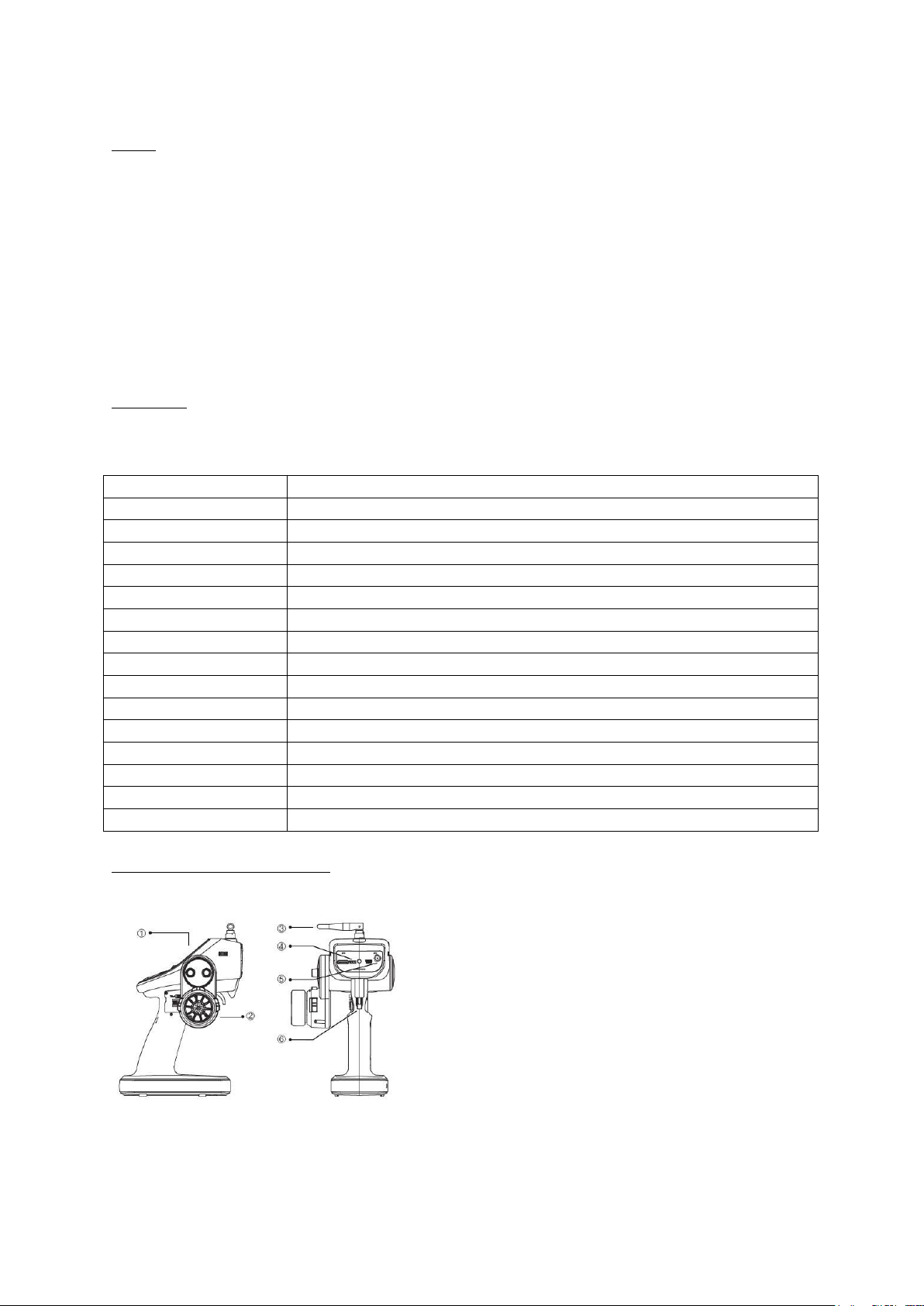
Product Structure (Mechanical parts)
① Operating Panel, ②Steering Wheel, ③Antenna, ④Communication Port, ⑤Charging connector, ⑥Trigger
Page 3
Operation
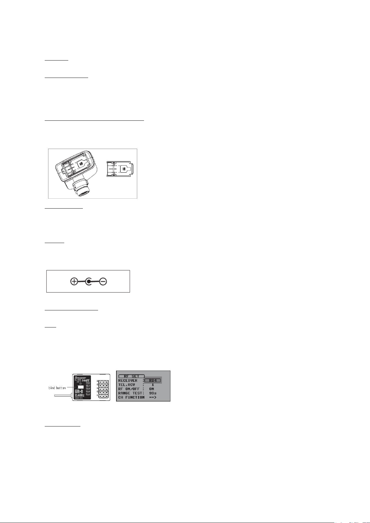
Battery Connection
• Only use optional NiCd /NiMH 1.2volt, AA size rechargeable battery and Li-Po battery.
• Remove the cover and install your battery to battery socket. Then, replace the cover making sure it is closed securely.
• When low voltage warning alarm is activated, please use new battery or recharge the used battery. Please make sure the
correct polarity when installing your battery.
Low-voltage warning for transmitter battery
Please charge Nixx 4 cell battery before use. When it will beep continuously due to low voltage warning, please stop an
operation, then recharge your battery or replace it.
Battery Charging
If rechargeable battery is in use, you can charge it below 1.0A using the charging socket of the radio or after
disconnecting the battery. When charging after disconnecting battery, please sue the JR type charging socket.
Cautions
The improper use will cause fire. So please use rechargeable battery and keep the safety rules.
Reference picture (Correct polarity)
Biding and Range Test
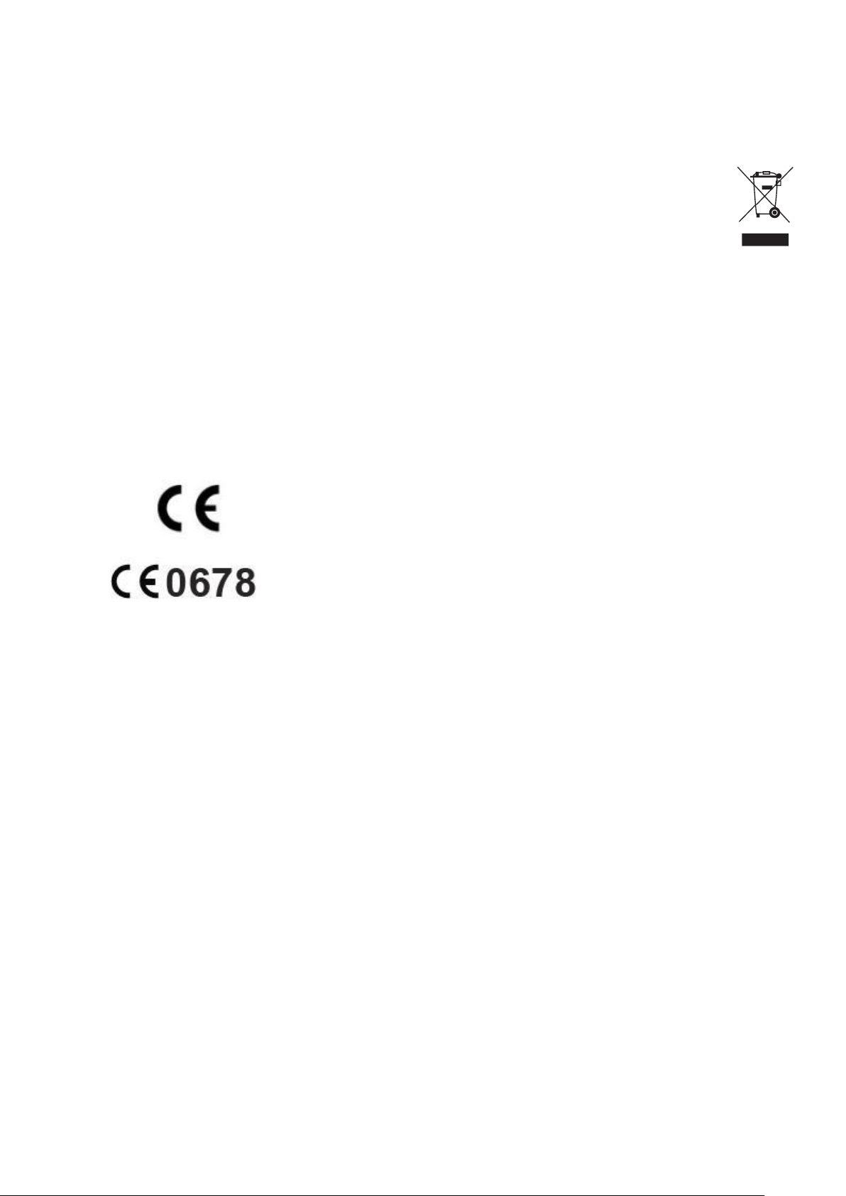
BIND
Please put the cursor on “RECEIVER” of RF SET Manu of the Radio. And press and hold the Bind button of the receiver
during 3 seconds. And the LEDs of the receiver blink in green and red colors. At this time, please press enter at the
“RECEIVER” of the radio. After completing, the Green LED of the receiver shall be on. Otherwise, please return to the first
step again.
RF RANGE TEST
When BIND button is touched after the connection between transmitter and receiver, RF RANGE TEST is now activated. RF
TEST is continued during 99 seconds and it is automatically deactivated. RF RANGE TEST is deactivated by touching BIND
button during RF RANGE TEST mode. Please note that your model is not controlled if your model is far away from the
transmitter during Test mode due to the short transmit distance.
Page 4

Menu
1. Main Screen
① Current Model No. and Name
② Dual Rate, ATL, 3CH, 4CH
③ Steering Trim
④ Throttle Trim
⑤ Radio Voltage and use time of Battery
⑥ TX, RX RF Antenna
⑦ Earphone Jack, SD card icon
⑧ Key holder icon.
When you press and hold the button, the key will be hold status. And the key mark will be
represented. When you press and hold the button again, it will be deactivated.
⑨ User’s Name or Voice Function announcement title
⑩ Driving time
⑪ Up and Down Timer
⑫ Lap tire, Lap Counter
Page 5

Red LED
Transmitter Power On
Blue LED
RF On
Warning
Sequentially blinks in Red, Blue LEDs
Function Warning
Red LED blink
Range Test
Blue LED blink
1) : m a i n m e nu, m o v e t o m a i n p a g e
2)
3) :
4)
5)
6)
7)
8)
: e s c a pe k e y
enter key
: me n u m o v i n g a n d s e t t i n g
(DEC+INC+ENT) : me n u k e y h o l d (Push
(FUN + ESC) : S c r e e n f o r S e r v o
(INC+DEC) : i n i t i a l i z i n g
(UP+DOWN) : m o v e t o h i d d e n m o d e
Status explanation of LED Indicator
2. Switch
2sec)
The switch and steering wheel are operated for right and left hands. (one side for TR4,5 and PB2)
TR 1 ~ 5 are for push button function (TR1A~TR5B)
Page 6

3. Main Menu
There are 4 pages and they could be moved by FUN switch.
: Next Page
: move
1)
MOD. SEL : model memory
2) MOD NAME : model name change
3) MOD COPY : mo d el m e m o ry c o p y
4) MOD RES : m od e l m em o r y d e l e t e / r es e t
5) RF SET : RF b i n d i n g / r a n ge t e s t
6) REVERSE : s e rv o r e ve r se
7) E.P.A : m a xi m um r u d d er an g le
8) DR/EXPO : d u a l r at e , e x p o ne n ti a l, th r ot t le c u r v e
9) TRIM : t r i m , s u b t r i m
10) B.R.A : b ra k e a dj u st m e nt (ATL)
11)
TH RESP : t hr o tt l e r e ac t io n s p ee d
12) TIMER : l a p t i re , u p /d o w n t i r e , l a p ti r e l og an d s e a rc h
13) S/SPEED : s te e ri n g, t h r o tt l e s er v o s pe e d
14) FAIL SAFE : f ai l s a f e
15) A.B.S : A.B.S brake system
16) IDLE UP : i dl e u p
17) TH PUM: t h r ot tle PUMPING
18) START : st a r t f u n c t i o n
19) P/MIX : p ro g ra m m i x
20) HW SET : ha r dw a re sw i t c h c o n f i g ur a ti o n
21) SW FUN: s w it c h fu n c t io n c o n f i g ur ati o n
22) S/MODE : s p ec i a l f u n c t i o n
23) SERVO : s er v o o pe r a t i o n v i e w
24) AUX : 3,4 channel adjustment
25) SYSTEM : s y st e m c on f ig u ra t io n
26) TELEMETRY : t e le m et r y c o n f i gu r a t i on
: Menu select
Page 7
ENVIORNMENTAL PROTECTION NOTES
This product must not be disposed of with other waste. Instead,
it is the user’s responsibility to their waste equipment by handing it over to a designated
collection point for the recycling of waste electrical and
electronic equipment. The separate collection and recycling of
your waste equipment at the time of disposal will help to conserve natural resources and ensure that it is recycled in a
manner that protects human health and the environment. For more information about where you can drop off your waste
equipment for recycling, please contact your local city office, your household waste disposal service or where you
purchased the produce
1) Conformite Europeenne
Product(s): Graupner X-8N Transmitter,
Item Number(s): No. S1018 , No 33504
- EN 62479:2010
- EN 60950-1:2006/A11:2009/A1:2010/A12:2011
- EN 301 489-1 V1.9.2
- EN 301-489-17 V2.2.1
- EN 300 328 V1.8.1
2) FCC Information
Graupner X-8N Transmitter
FCC ID: SNL-16006200
FCC Statement
1. This device complies with Part 15 of the FCC Rules. Operation is subject to the following two conditions:
1) This device may not cause harmful interference.
2) This device must accept any interference received, including interference that may cause undesired operation.
2. Changes or modifications not expressly approved by the party responsible for compliance could void the user‘s
authority to operate the equipment.
Page 8

z NOTE
This equipment has been tested and found to comply with the limits for a Class B digital device, pursuant to Part 15 of the FCC
Rules.
These limits are designed to provide reasonable protection against harmful interference in a residential installation. This
equipment generates uses and can radiate radio frequency energy and, if not installed and used in accordance with the
instructions, may cause harmful interference to radio communications. However, there is no guarantee that interference will not
occur in a particular installation.
If this equipment does cause harmful interference to radio or television reception, which can be determined by turning
equipment off and on,
the user is encouraged to try to correct the interference by one or more of the following measures:
Reorient or relocate the receiving antenna.
-
Increase the separation between the equipment and receiver.
-
Connect the equipment into an outlet on a circuit different from that to which the receiver is connected.
-
Consult the dealer or an experienced radio/TV technician for
help.
the
 Loading...