

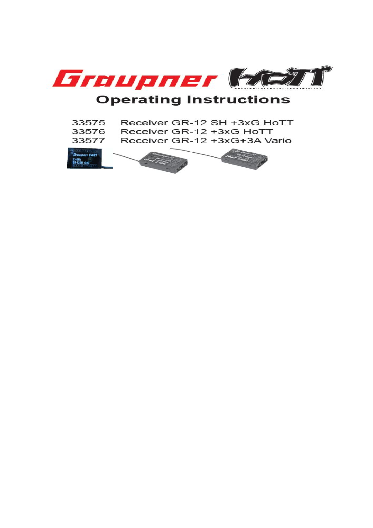
Page 1
1. Notes......................................................................................................................19
2. Functions...............................................................................................................21
2.1. Binding.........................................................................................................21
2.1.1 Binding multiple receivers...................................................................................21
2.2. Fail-Safe function...............................................................................................21
2.3 Range-checking...........................................................................................22
3. Receiver..................................................................................................................23
3.1. Connections..................................................................................................24
3.2. Receiver set-up menu........................................................................................25
3.3. Free mixers.......................................................................................................25
3.4 Assigning the gyro axes......................................................................................27
4. Programming the gyro settings...............................................................................29
4.1. Programming PID correction..............................................................................29
4.2. Programming the factors....................................................................................30
4.2.1 Programming, transmitter with proportional controls............................................30
4.2.2 Programming, transmitter without proportional controls.......................................31
4.3 Initialising the gyro............................................................................................31
5. Conformity declaration / Guarantee / Manufacturer’s declaration / Disposal..50
Page 2

MANY THANKS
for deciding to purchase the Graupner/SJ HoTT 2.4 system. Please read right through these
operating instructions before you attempt to install and operate the Graupner HoTT 2.4 system.
• The receiver stabilises the model aircraft in difficult, windy conditions, acting on a maximum of
three axes
• Proportional gyro suppression for natural flying characteristics
• Excellent stabilisation for smooth, accurate manoeuvres
• The triple-axis gyro endows even very demanding aerobatic models with docile flying characteristics,
and greatly simplifies aerobatics
• Aerobatic manoeuvres can be flown much more accurately
• Simple gyro assignment procedure
• Facility to adjust parameters using HoTT telemetry
• Altitude sensor for vario and altimeter function (Order No. 33577)
1. APPROVED USAGE
The receiver is intended exclusively for use in radio-controlled models. Any other usage is prohibited,
and may result in damage to the receiver or model, and serious personal injury. We grant no
guarantee and accept no liability for any type of use outside the stipulated range.
Not suitable for children under fourteen years. This receiver is not a toy!
The receiver is also equipped with a telemetry function which is only available in combination with a
Graupner/SJ HoTT 2.4 system. If you do not own a Graupner/SJ HoTT 2.4 system, the receiver will
not work.
Please start by reading through the whole instructions before you attempt to install and operate the
receiver.
These operating instructions are an integral part of the product. They contain important notes on
operating and handling the receiver. For this reason please store the operating instructions in a safe
place, and pass them on to the new owner if you ever dispose of the product. Failure to observe the
operating instructions and safety notes invalidates the guarantee.
Here at Graupner we are constantly working on the further development of all our products; for this
reason we are obliged to reserve the right to introduce changes to the set contents in form,
technology and features.
Please understand that we will not countenance claims resulting from information and illustrations in
these operating instructions.
Please store the operating instructions in a safe place for future reference!
Page 3

1.1 SAFETY NOTES
KEY TO THE SYMBOLS
Page 4

1.2 GENERAL NOTES
• The receiver’s integral gyros are very fast, high-resolution components. This means that you
should always use high-speed digital servos wherever possible, so that the gyro’s corrective
signals are converted directly and accurately into servo movement; this helps to prevent the
model oscillating.
• Keep all servo extension leads as short as possible.
• When switching on or adjusting the radio control system, it is essential to keep the transmitter
aerial at least 15 cm from the receiver aerial(s). If the transmitter aerial is too close to the receiver
aerials, the receiver will be swamped and the red LED on the receiver will light up. The transmitter
responds with a flashing red LED and repeated beeps at approximately one-second intervals, i.e.
the radio control system reverts to fail-safe mode. If this should happen, increase the distance
until the audible warning ceases, and the blue transmitter LED lights up constantly once more.
The red LED on the receiver should now be off.
2. FUNCTIONS
2.1. Binding
The Graupner/SJ HoTT 2.4 receiver must be “bound” to “its” Graupner/SJ HoTT 2.4 RF module
(transmitter) before a radio link can be created between them; this process is known as “binding”.
Binding is only necessary once for each combination of receiver / RF module, so the binding
procedure described below only needs to be repeated if you add more receivers. However, binding
can be repeated at any time if you wish; for example, if you switch transmitters. This is the procedure
in detail:
• Binding is only possible if the receiver has not been linked with a bound transmitter since being
switched on (red LED lights); press the SET button to set the receiver to BIND mode.
• If you have already bound a receiver to the transmitter, and wish to bind the receiver to a new
model memory, this is the procedure:
• Switch the transmitter’s RF section off in the “Basic model settings” menu.
• Switch the receiver on, and press the SET button to set it to Bind mode.
• Initiate binding in the transmitter’s “Basic model settings” menu.
• The red receiver LED should go out within about ten seconds. If it does, the binding process has
been completed successfully.
• Your transmitter / receiver combination is now ready for use.
• However, if the red LE D continues to glow, then the binding process has failed. If this should
happen, repeat the whole procedure.
2.1.1. Binding multiple receivers per model
If necessary it is also possible to bind more than one receiver to a particular model. First bind each
receiver individually as described earlier.
When the system is actually in use, the receiver which was last bound acts as the Master unit, and
any telemetry sensors installed in the model must be connected to this receiver, as only the Master
receiver transmits the data to the ground using the downlink channel. The second - and any other –
receivers operate in Slave mode, in parallel with the Master receiver, with the downlink channel
switched off. The channel mapping function of HoTT telemetry also allows the control functions to be
divided up amongst multiple receivers, or alternatively the same control function to be assigned to
multiple receiver outputs. For example, this is useful if you wish to actuate each aileron with two
servos instead of just one.
2.2. Fail-Safe function
In the receiver’s default state, all connected servos remain in their last valid position (“Hold” mode)
if a fail-safe situation should arise. In fail-safe mode the red LED on the receiver lights up, and the
transmitter generates an audible alert by beeping at a rate of around one per second.
You can exploit the safety potential of this option by at least setting the throttle position (for
internalcombustion powered models) to Idle, or the motor function (electric-powered models) to “Stop”,
Page 5
or “Hold” for a model helicopter, if a fail-safe event should occur. These settings ensure that the model
is less likely to fly out of control if interference should occur, thereby helping to avoid property damage
or even personal injury.
Read the operating instructions supplied with your radio control system for more details.
The gyro system remains active in a fail-safe situation.
2.3 Range-checking
The range of your Graupner/SJ HoTT 2.4 system can be checked as described in the following
instructions. We recommend that you ask a friend to help you with the procedure.
Ideally the receiver should already be bound to the transmitter. Install it in the model in its final
position.
• Switch the radio control system on, and wait until the red LED on the receiver goes out. The servo
movements can now be observed.
• Place the model on a flat surface (pavement, close-mown grass, earth), and ensure that the
receiver aerials are at least 15 cm above the ground. It may be necessary to pack up the model
to achieve this for the period of the range-check.
• Hold the transmitter away from your body at hip-level. Don’t point the transmitter aerial straight at
the model; instead rotate or angle the aerial tip in such a way that it is vertical when you operate
the transmitter controls.
• Select range-check mode, as described in the transmitter instructions.
• Walk away from the model, moving the transmitter sticks. If you detect an interruption in the radio
link at any time within a distance of about 50 m, see if you can reproduce the problem.
• If your model is fitted with a motor or engine, switch it on or start it, so that you can check effective
range when potential interference is present.
• Walk further away from the model to the point where full control is no longer possible.
• At this point you should manually switch off range-check mode.
The model should now respond to the controls again. If this is not 100% the case, do not use the
system. Contact the Graupner/SJ Service Centre in your locality and ask their advice.
We recommend that you carry out a range-check before every flight, simulating all the servo
movements which occur in flight. To guarantee reliable model operation, radio range must always be
at least 50 m on the ground.
2.4 INSTALLATION IN THE MODEL
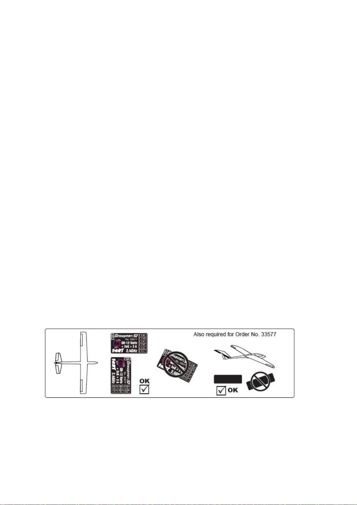
The gyro-receiver must be installed “square” relative to the model, i.e. at right-angles to the aircraft’s
longitudinal axis, otherwise the gyros will be unable to function as intended (Order No. 33577 must
also be horizontal relative to the fuselage centreline to allow the accelerometer to work correctly).
Page 6
3. RECEIVER
3.1 Connections
Connect the servos to the row of sockets on one end of the receiver. The connectors are polarised:
note the small chamfers on one side. Never use force - the connectors should engage easily. The
polarity is also printed on the receiver; the negative wire (-) is brown, the positive (+) red and the
signal orange. The servo sockets of Graupner/SJ HoTT 2.4 receivers are numbered sequentially.
The socket for channel 6 can also be programmed to deliver a (digital) sum signal (see section 3.2:
Receiver set-up).
I²C (Inter-Integrated Circuit) - socket currently not active; for servicing purposes only!
Power supply
The receiver does not feature specific sockets for connecting the battery. We recommend that you
connect the power supply to the socket(s) close to the servos already connected to the receiver. If you
wish to connect multiple separate batteries, the batteries must be of the same nominal voltage and
capacity. Never connect batteries of different type, or packs of greatly differing states of charge, as
this can cause effects similar to a short-circuit. If you encounter this problem, we recommend the use
of a voltage stabiliser unit (e.g. PRX-5A receiver power supply, Order No. 4136) between the batteries
and the receiver .
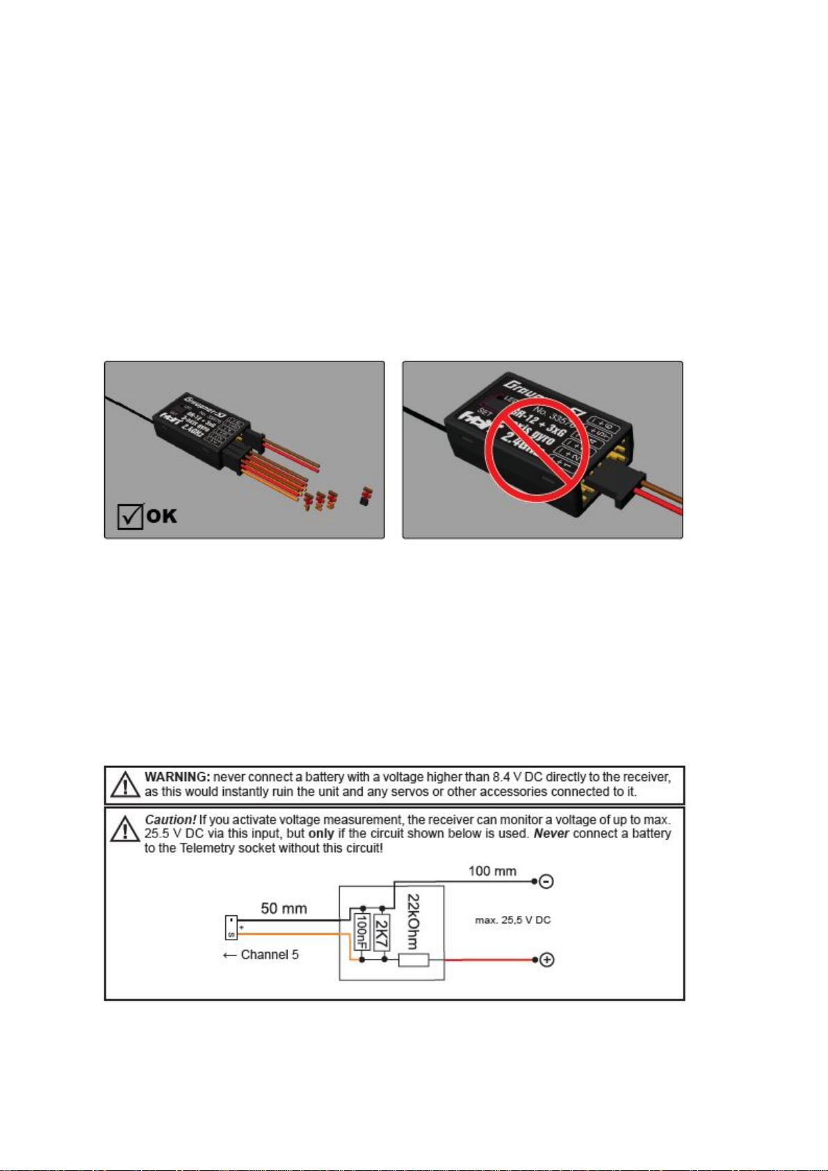
Telemetry
The optional telemetry sensors are connected to the socket marked “T” (Telemetry). Alternatively the
receiver can monitor a voltage up to max. 25.5 V DC via this socket.
NOTE: you can either connect this socket to a servo or a telemetry sensor or the battery to be
monitored; the receiver must be set up accordingly. Please see the following section for further details.
Page 7

PROGRAMMING THE GENERAL RECEIVER SETTINGS:
The receiver can be programmed using a suitable HoTT transmitter or the SMART-BOX (Order No.
33700).
3.2 RECEIVER SET-UP MENU
The receiver set-up menu appears in the “Telemetry” menu
under SETTINGS / DISPLAYS; alternatively - if you are using a
SMART -BOX - under SETTING & DATAVIEW. The method of
accessing this menu is described in the operating instructions
supplied with your transmitter or the Smart-Box.
Indicates the receiver status
Low-voltage warning (ALARM VOLT): if the receiver voltage or the external voltage connected to
channel 5 falls below the set value, a low-voltage warning is generated by the transmitter’s RF
module in the form of the “general alarm tone”: a regular beeping at a rate of about one per second;
alternatively the speech output message “Receiver voltage”.
Temperature warning (ALARM TEMP): if the receiver temperature exceeds the set temperature
threshold, a warning is generated by the transmitter’s RF module in the form of the “general alarm
tone”: a regular beeping at a rate of about one per second; alternatively the speech output message
“Receiver temperature”.
Maximum height (Max. height) - Order No. 33577 with integral vario only: at this point you can
enter a maximum altitude, at which an alarm is triggered, either via the transmitter’s RF module in the
form of the “general alarm tone”: a regular beeping at a rate of about one per second; alternatively the
speech output message “Height”. Note: the model’s actual height is adopted as zero when the
receiver is switched on; the indicated height is therefore the altitude relative to the launch point.
Cycle time (CYCLE): if your system is used exclusively with digital servos, you can set a cycle time
(frame rate) of 10 ms at this point. If your system includes some or all analogue servos, you should
always select 20 ms, as many analogue servos cannot process the higher frame rate, and may
respond by “jittering” or “growling”.
HoTT sum signal (SUMD): if you activate the digital sum signal at channel 6, a sum signal containing
eight channels is present at this socket, instead of a servo signal. The HoTT receiver configured as
SUMD constantly generates a digital sum signal from 8 control signals from the transmitter and
makes this signal available at the appropriate servo socket, which is receiver-specific. At the time
these instructions were revised, this type of signal is used by several of the latest electronic
developments in the area of flybarless systems, heavy-duty airborne power supplies, etc.
WARNING: if you wish to use this facility, it is essential to observe the set-up information supplied
with the devices connected to the receiver, otherwise there is a risk that your model may be
Page 8

uncontrollable.
Channel 5 (Ch5): channel output 5 can be used to control a servo, as a telemetry socket or for
voltage monitoring. If you activate voltage monitoring, the receiver can measure a voltage of up to
max.25.5V DC via this input (instead of a servo or telemetry sensor) using the circuit described in
section 3.1. The monitored voltage is then displayed on the screen instead of the receiver voltage.
This makes it possible, for example, to monitor the flight battery directly, without the need for an
additional voltage sensor. If channel 5 is set to ‘sensor’ or ‘voltage’ instead of servo, the channel
5 signal is automatically available at channel 6. This change will not take effect until turning on
/ off the receiver.
3.3 FREE MIXERS
MIXER: up to four mixers can be programmed simultaneously. You can switch between Mixer 1,
Mixer 2, … and mixer 4 in the “Mixer” line.
The following settings only affect the mixer selected in this line.
FROM CHANNEL: the signal present at the signal source (or source channel) is mixed in to the
target channel (TO CHANNEL) to an extent which can be set by the user. The method of setting
up the values is analogous to the “Free mixers” menu in HoTT transmitters.
TO CHANNEL: part of the source channel signal (FROM CHANNEL) is mixed into the target
channel (TO CHANNEL). The mixer ratio is determined by the percentage values entered in the
“TRA VEL-“ and “TRAVEL+” lines. Select “0” if you do not require the mixer.
Mixer ratio (TRAVEL-/+): in these two lines you can define the mixer ratio in relation to the
source channel (FROM CHANNEL); the value is set separately for both directions.
Programming examples:
V-tail with rudder differential
Differential is not normally necessary with this tail type. Mixer 3 is not required if you do not
need rudder differential, and TRAVEL- for mixer 2 must then be set to -100%.
Alternatively you may prefer to carry out the programming using the transmitter menu. A
Page 9

‘Rudder elevator’ mixer can be set up at the transmitter instead of ‘Free mixer 3’ at the receiver;
the mixer should be set up asymmetrically, e.g. +30%, -30%. This option frees up one mixer at
the receiver.
Delta with aileron differential (1 aileron)
In this example aileron differential is set to 40%. Alternatively you may prefer to carry out the
programming using the transmitter menu. An ‘Aileron elevator’ mixer can be set up at the
transmitter instead of ‘Free mixer 3’ at the receiver; the mixer should be set up asymmetrically,
e.g. +30%, -30%. This option frees up one mixer at the receiver.
Two elevator servos
(channel 6 for the second elevator servo)
Page 10

Aileron servos: you should enter the value 2 in this line if your model has two aileron servos;
in this case the gyro for channel (servo) 2 also acts on servo 5. If the ailerons are also used as
flaperons or speed brakes, gyro suppression is based on the sum of both channels.
Please read the installation notes on page 5 of these instructions. The first step is to define the
three gyro axes and the orientation of the receiver. This is accomplished by switching on the
transmitter and model, and selecting ‘New setting: yes’ in the receiver’s ‘Gyro settings’ menu.
• Now move the stick for any control surface to full travel in one direction; in the following
example we use the aileron channel.
• The detected axis (aileron) is highlighted (black background). (In the receiver’s default state
the value for all axes is shown as ‘+0’; the axes can also be set manually to ‘+0’. 0 = inaktiv)
• Now turn the model through at least 45° in the direction corresponding to the stick
movement. For example, if you moved the aileron stick to the left, you must simulate a left turn
with the model and move the left wing down through at least 45°.
• This process defines the one axis and direction; now you must repeat the procedure for the
other two axes.
• The gyro axis 1, 2 or 3 is now displayed in the ‘Aileron / Elevator / Rudder’ display; a
negative prefix will appear if servo reverse is activated.
Once all three axes are defined, the display automatically reverts to ‘Ne w setting: no’.
Page 11

4. PROGRAMMING THE GYRO SETTINGS:
PID (Proportional Integral Differential) correction
The stabilising effect of the gyro sensors is based fundamentally on three parameters:
P factor: defines proporti onal correction
P = proportional: if the intended value is not the same as the actual value, then the difference
is fed proportionally into the corrective signal; in simple terms, the input value (e) is multiplied
by a fixed value: u(t) = Kp*e(t). Kp is termed the amplification value. The output value is
therefore proportional to the gyro’s input value. Proportional correction cannot occur until a
deviation from the intended value is present; if the deviation is 0, then the product is also zero.
If the amplification value is set too high, the P factor causes the model to oscillate and become
unstable.
I factor: integral correction (not currently implemented)
D factor: defines differential correction
Page 12

D = differential: in this case the corrective output value is affected by the rate of change of the
input value, i.e. the faster the model tilts around the axis, the more pronounced the corrective
response of the gyro. If the model changes attitude very gently, then the D factor causes
hardly any corrective action. It also makes absolutely no difference how far the model has
already changed attitude; the crucial value is only the speed or rate of the movement. The rate
of change is again multiplied by a factor (as with P correction) to produce the output value. For
this reason pure D correction is not used; it must always be employed in combination with P
correction.
4.1 Programming PID correction - Gyro settings display:
Aileron / Elevator / Rudder: shows the programmable P factors for the corresponding control
surface.
Note: the gyro axes must first be defined under New settings (see section 3.4).
If you wish to disable the gyro, enter the value OFF in the appropriate control function.
P factor:
The P factor should always be set first, followed by the D factor (adjustment range in each
case 0 to 10). A general rule is that the larger the control surface, the smaller the P factor
required. Start with a factor of 2 (default setting), and do not exceed 4 - 5 as maximum value
for the normal flight phase, 2 - 3 for speed, 3 - 6 for landing; the maximum value of 10 should
be reserved for torque-rolls only.
Note: the higher the model’s speed, the more quickly oscillation may set in.
D factor: for a given P factor setting, the model’s tendency to oscillate can be reduced by
setting a lower D factor. However, if you select a lower setting for the P factor, then you may be
able to set a higher D factor value before the onset of control surface oscillation. The gyro
effect can be optimised by fine tuning the D factor.
Note: the standard P and D values should cause the gyros to correct the model’s attitude
quickly when it is upset by an outside influence, without causing oscillation, but in practice
the optimum values for a particular model can only be found by flight-testing. If the model
displays little or no automatic stabilization with the default settings, the value should be raised;
on the other hand, if the model oscillates (wave-like movements in flight), the value should be
reduced. If your transmitter has spare proportional controls, you can use them to adjust the
values while the model is flying. Some transmitters allow the corrective factors to be altered
during a flight using the proportional controls, whereas others allow fixed values only.
4.2 Programming the factors
4.2.1 Programming, transmitter with proportional controls
If your HoTT transmitter is equipped with proportional controls, it is also possible to adjust the
P and D factors for each axis during a flight: what you might call ‘flying the settings’. You need
to assign proportional controls (e.g. the sliders on the mc-20) to any channel in the range 5 to
16 (in this example channel 9); now you can alter the P factor (and the D factor) using these
controls. In each case the current values are shown in brackets.
Page 13

Procedure, using the ailerons as an example:
• Move the cursor to the appropriate line, in this case “Ail”
for aileron.
• Press the SET button to activate the Channel field.
• Select the appropriate channel, and save the setting with
pressing the SET button again
• move the corresponding proportional control to alter the
factor (adjustment range 0 - 10; 0 means no gyro correction
for that axis).
• You can also adopt this factor directly by pressing the left button < or the right button >. This
frees up the channel previously occupied by the proportional control, so that it can be used for
some other purpose, e.g. for elevator or rudder.
• Move on to elevator and / or rudder, and select the channel and factor (you can either select
the same channel, in order to alter all the axes simultaneously, or different channels, allowing
you to program the axes individually).
• Move the cursor to the Factor line, where you can also change the P factor for aileron,
elevator and rudder with priority (adjustment range up to 200%).
• Move the cursor to the D factor line, where you can alter the D factor for aileron, elevator and
rudder with priority using a proportional control (adjustment range up to 200%; channel value
-100% equates to a factor of 0%, channel value 0% equates to 100%, and +100% equates to
200%). This makes it a very easy matter to match the gyro’s corrective effect to the model’s
airspeed. In particular, higher gyro gain can be used for the landing approach - without the
need to switch flight phases.
• Now test-fly your model and fine-tune the values one by one until your preferred stabilising
effect is achieved without the model oscillating.
• It may be sensible or easier to activate the gyro for one axis only at first, and then to
establish the optimum setting for that axis, rather than for several axes simultaneously.
Page 14

4.2.2. Programming, transmitter without proportional controls
• Move the cursor to the appropriate line, in this case “Ail” for
aileron.
• Press the SET button to activate the Channel field, select the
appropriate value (1 - 10 of OFF), then press the SET button to
save it.
• First select a low value (see P factor section for starting
points) and carry out a test-flight. If gyro stabilisation is not
sufficiently pronounced, increase the value step by step
until the level of correction is as required; if the model already oscillates, reduce the value
step by step.
• Do not select a channel (Ch5 - Ch16); this function is only relevant to transmitters with
proportional controls.
• Move on to elevator or rudder and select the desired value (or OFF).
• Leave the settings for “Factor” and “Factor D” at OFF.
• It may be sensible or easier to activate the gyro for one axis only at first, and then to
establish the optimum setting for that axis, rather than for several axes simultaneously.
Once you have found the optimum settings, you can set up a transmitter switch to control the
gyro, i.e. for switching between gain settings. For example, you could assign a three-position
switch to “Factor” and “Factor D”, and then use it to switch the values between 0% (OFF), 100%
and 200%.
Flight phase specific settings
It is possible to use a channel to control the factor value by setting up flight phase specific
transmitter control settings, but only if the transmitter is an MX20 / MC20 or MC32; please see
the instructions supplied with your transmitter and refer to the “Transmitter control settings”
and “Flight phase settings” menu points for more information.
4.3 Initialising the gyro
After switching on the model of the gyroscope is immediately active but not yet initialized. To
initialize it, you keep your model when switching quiet and straight in level flight - the best
place it on the flat ground or a flat table. After about 2 seconds, the ailerons move up and
down just once. This “wiggle” signaled the successful initialization, the end of the calibration,
only then the model may be moved again. All sticks are to b e kept s trictly in neutral!
Page 15

Page 16

COMPLIANCE INFORMATION FOR THE EUROPEAN UNION
1)KC
Graupner GR-12SH+3xG Receiver
KCC 인증번호: MSIP-CRM-sjr-16006000
2)Conformite European
Graupner GR-12SH+3xG Receiver
Item Number: no.33575
-EN 62479:2010
-EN 60950-1:2006/A11:2009/A1:2010/A12:2011
-EN 301 489-1 V1.9.2
-EN 301-489-17 V2.2.1
-EN 300 328 V1.8.1
(3) FCC Information
Graupner GR-12SH+3xG Receiver
FCC ID: SNL-16006000
FCC Statement
1. This device complies with Part 15 of the FCC Rules. Operation is subject to the following
two conditions:
(1) This device may not cause harmful interference.
(2) This device must accept any interference received, including interference that may cause
un- desired operation.
2. Changes or modifications not expressly approved by the party responsible for compliance could
void the user‘s authority to operate the equipment.
• NOTE
This equipment has been tested and found to comply with the limits for a Class B digital device,
pursuant to Part 15 of the FCC Rules.
These limits are designed to provide reasonable protection against harmful interference in a residential installation. This equipment generates uses and can radiate radio frequency energy and, if not
installed and used in accordance with the instructions, may cause harmful interference to radio
communications. However, there is no guarantee that interference will not occur in a particular
installation.
If this equipment does cause harmful interference to radio or television reception, which can be
determined by turning the equipment
off and on, the user is encouraged to try to correct the interference by one or more of the following
measures:
- Reorient or relocate the receiving antenna.
- Increase the separation between the equipment and receiver.
- Connect the equipment into an outlet on a circuit different from that to which the receiver is
connected.
- Consult the dealer or an experienced radio/TV technician for help.
• FCC radiation exposure statement
This equipment complies with FCC radiation exposure limits set forth for an uncontrolled environment.
This equipment should be installed and operated with minimum distance of 20 cm between the
radiator and your body.
Page 17

 Loading...