

Page 1

X-4S MANUAL
Contents
Before use--------------------------------------------- ----------
• Support and Service-----------------------------------------------
- Customer Support------------------------------------------------------------
- Internet sales site -----------------------------------------------------
- A/S support & Warranty information ------------------------------------------------------
- OPENHOBBY A/S SUP P ORT AND SERVICE CENTER -------------
• Box Contents-----------------------------------------------------------------
• Safety Warning Notes-----------------------------------------------------------
• System Features-----------------------------------------------------------------
• Specification-------------------------------------------------------------------
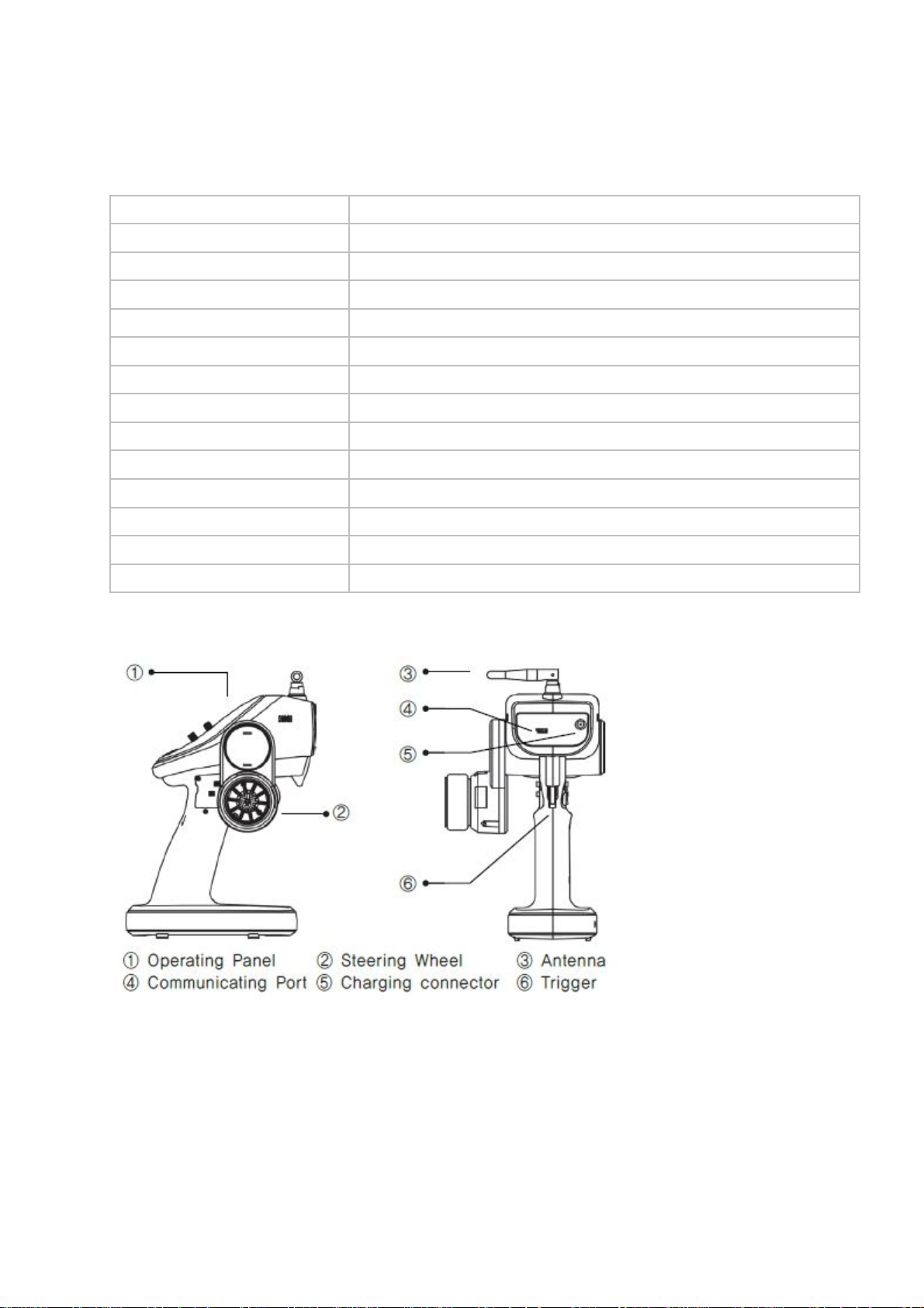
• Product Description--------------------------------------------------------------
• HoTT
• Operation
• Receiver installation
• Steering & Trigger tension adjustment
• Steering wheel position adjustment
• Trigger Angle Adjustment
• Installation for left-handed users
• Binding and Range test
• Control Switch Functions--------------------------------------------------------------- ----P7
• Fail Safe mode Configuration -------------------------------------------------------------------------
• Trigger and Steering Calibration ------------------------------------------------------
• LED and Buzzer Indication------------------------------------------------------------------------
• Receiver port Description
• Smart Box (Configuration by Telemetry)
• Safety
BEFORE USE
Thank you for purchasing Graupner/SJ X-4S HoTT 2.4GHz Radio System. This system is extremely
versatile and may be used by beginners and pros alike. In order for you to make the best use of your
system, please read this manual carefully. If you have any difficulties while using your system,
please consult the manual, our online Frequently Asked Questions (on the web pages referenced
below), your hobby dealer, or the Graupner/SJ Service Center. Due to unforeseen changes in
production procedures, the information contained in this manual is subject to change without notice.
SUPPORT AND SERVICE
• Customer support
We are happy to assist you with any question by e-mail or phone, Customer service hours are 9 AM
to 5 PM (Pacific Standard Time) during the workweek, Monday through Friday. E-mailed questions will
be answered as soon as possible.
• Internet sales site
Please visit us at www.openhobbby. co m
• A/S support
During the warranty period, we can repair this product at no cost for products that have become
faulty under normal operating conditions. For non-functional products that are past the expiration date
of the warranty or have been improperly used, we would be happy to repair this product for an
appropriate amount of cost to the consumer
• Warranty information
, for more information
Page 2

Refer the WARRANTY CARD in the Package
OPENHOBBY A/S SUPPORT AND SERVICE CENTER
기존 사용내용 기재
BOX CONTENTS
X-4S HoTT Transmitter
Warranty Card
GR-4 Receiver
Temperature / Voltage Sensor (S8362)
Battery Holder
Alkaline 4 cells
Manual
SAFETY WARNING NOTES
• Never operate your car or truck in a crowded street with traffic. Especially, do not drive in a place
near railway, chemical substance, gas to prevent any damage.
• This product is not intended for use by inexperienced or disabled person without direct supervision
of a responsible, knowledgeable adult. This is not suitable for child ren under 18 years.
• This warranty does cover damaged products arising as a result of production process. It is not
allowed to use to those who are the disabled or do not have enough knowledge.
• The radio system is affected by signal environment and the electronic jamming signals can cause
disorientation and loss of control of your aircraft.
• Please read the manual to make the best use of the product
• Make sure to check all operations of channels before use.
• For the safe use, please operate the Range Check Mode before use.
• Be careful not to turn your transmitter off while in use.
• Do not touch or grab antenna during the use.
• Do not operate your model in the rain or run through standing water
• Fail Safe should be set before use to prevent uncontrollable situation occurred by any interruption.
It is recommended to set throttle channel to Neutral condition or brake condition.
• Always operate your program setup mode after stopping motor’s power or engine and disconnecting
drive battery.
• Make sure whenever you start operating your transmitter, turn your transmitter before switching your
receiver switch. Whenever you stop your transmitter, turn your receiver off before your transmitter is
switched off.
• Always use new battery pack or charge your battery fully to avoid possible hazard causing by low
battery capacity.
• Always be sure to check your battery capacity for your transmitter and receiver.
• As for boat model, we recommend installing your antenna vertically to the exterior boat and
operating Range Check Mode for the best use of your model.
Page 3

System Features
1. HOPPING TELEMETRY TRANSMISSION (HoTT)
The use of up to 35 hopping channels provides advanced reliable operation while keeping from any
external interference.
2. Designed for beginners, X-4S HoTT Transmitter is the best choice for those who enjoy car, boat,
and tank models. When optional Graupner/SJ Telemetry sensor or temperature sensor is used, you
may check the real-time information such as model voltage, user programmable warnings. It is easy
to check from your transmitter.
3. Unlike other binding systems which are widely used, X-4S HoTT Transmitter supports the fast
binding system which is operated by pressing a button.
Specifications
(1) X-4S Transmitter
Channel
2CH
Operating Voltage
Battery Type
Operating Current
Operating Output Power
Frequency
Modulation
Operating Temperature
Antenna
Display
Low voltage warning alarm
High temp warning alarm
Battery Charging
Extra Function
Size
Weight
4.8 ~ 6.0V
Alkaline, Nixx 4 Cell
app. 65mA
App. 60 mW
2.4000 ~ 2.4835 GHz
FHSS
app. -10 ~ +55`C
Dipole Antenna
LED Indicator
available (LED, Buzzer)
available (LED, Buzzer)
DC Jack
available (Futaba 3p connector)
( app. -50 ~ +131℉ )
171.1 x 292.0 x 139.8 mm ( 6.74 x 11.49 x 5.50 in.)
365.7g ( 12.89 oz )
Page 4
(2) GR-4 Receiver
Channel
Frequency
Modulation
Operating Voltage
Operating Output Power
Operating Current
Display
Extra Function
Fail Safe
Temperature Sensor Warning
Low voltage warning alarm
Telemetry Sensor
Size
Weight
Product description (Mechanical Parts)
2 CH
2400~2483.5 MHz
FHSS
3.6~8.4V
60mW
35.0mA
One LED (red)
available (Port3)
Free/Fail safe
(T/V Connector) Port4 (50~150℃)
(T/V Connector) Port4 (1.0~25.5V)
(B/T Connector) Port3
30x21x14.3 mm ( 1.18x0.82x0.56 in. )
app. 5.5 g (0.19 oz)
HoTT (Hopping Telemetry Transmission)
The use of up to 35 hopping channels provides advanced reliable operation while keeping from any
external interference. This HoTT radio system gives user real-time information on various useful data
such as user model’s RPM, voltage, temperature, user programmable warning, and so on.
X-4S HoTT Transmitter comes with GR-4 2Ch receiver.
Page 5
Operation
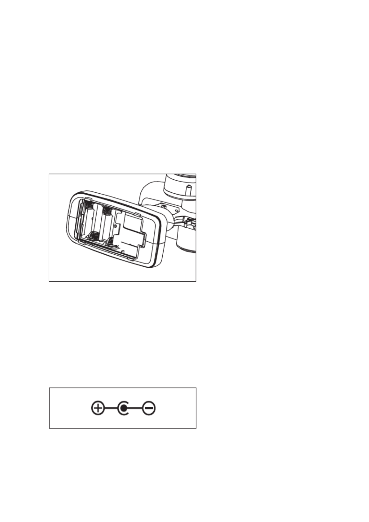
Battery Connection
• Only use optional manganese dry battery or NiCd /NiMH 1.2volt, individual AA size rechargeable
battery. (LiPo battery must not be used.)
• Remove the cover and install your battery to battery socket. Then, replace the cover making sure it
is closed securely.
• When low voltage warning alarm is activated, please use new battery or recharge the used battery.
Please make sure the correct polarity when installing your battery.
Low-voltage warning for transmitter battery
Please charge Alkaline 4 cell or Nixx 4 cell battery before use. When it will beep continuously due to
low voltage warning, please stop an operation, then recharge your battery or replace it.
(Do not use Lixx battery and please only use Alkaline or Nixx battery.)
Battery Charging
If rechargeable battery is in use, you can charge it up to 150mA with optional charging adapter.
We may notice that little heating will be occurred during use, which means it is working properly. Now
that this product features 4 cell battery packs, it is allowed to use within its specification. Otherwise, it
may cause damage to your model.
Cautions
The improper use will cause fire. So please keep the safety rules.
Reference picture (Correct polarity)
Page 6

Receiver installation
1. Install your receiver on the flat surface to avoid any oscillation.
2. Be aware you should keep your antenna at least 10mm away from any power wires to prevent
interference.
3. Be sure not to cut off any antenna wire, as it will shorten your operating range .
Steering and trigger tension adjustment
Steering wheel position adjustment
Page 7

Throttle Trigger Adjustment
Installation for Left-handed users
1. Disconnect your bolts and coverage.
2. Disconnect steering wheel part.
3. Disconnect transmitter connector.
4. Install your steering wheel part on your left side. Then, install the connector again then, coverage
and bolts. Now, your transmitter can be used for left-handed users.
Page 8

Binding & RF Range Test
BIND
Press and hold Bind button for 3 sec while your receiver is powered on and then LED indicator is off.
Now press Bind button of your transmitter and then receiver’s LED indicator is off.
RF RANGE TEST
When BIND button is touched after the connection between transmitter and receiver, RF RANGE
TEST is now activated. RF TEST is continued during 90 seconds and it is automatically deactivated.
RF RANGE TEST is deactivated by touching BIND button during RF RANGE TEST mode.
Please note that your model is not controllable if your model is far away from you during Test mode
due to the short transmit distance.
Control Switch Functions
1. REV (Reverse Switch)
This is used to change the direction of the servo travel for proper control when activated.
If you steer right and the wheels go left, change the “ST” switch from “Nor” to “Rev” or “Rev” to “Nor” if
needed. The same applies to the throttle.
2. ST D/R (Steering Dual Rate)
It is used to adjust the overall travel of the steering servo. (Adjustable from 0 % to 150%)
3. TH EPA-FW, EPA-BR (TH EP A-FW, EPA-BR)
This is used for throttle end point adjustment and for brake and reverse amount.
(Adjustable from 0% to 150%)
Page 9

4. TRIM
The trims are used to fine-tune the point where the servo returns to center.
(Adjustable from -37.5% to +37.5%)
ST: Use the ST-TRIM so your vehicle will go perfectly straight when the steering wheel is centered.
(Adjustable from -37.5% to +37.5%)
TH: Use the THR-TRIM to adjust the amount of brake that occurs when your engine’s idle is too low
or high and your ESC is not perfectly at neutral.
(Adjustable from -37.5% to +37.5%)
Fail Safe Mode Configuration
It should be programmed after binding process. The default value is “Fre e” mode.
Fail Safe is set to throttle channel (CH2)
Move your throttle to the position on which you act fail safe mode. Now touch and hold BIND button
for 3 sec until fail safe mode is set. (Buzzer beeps 3 times)
Press BIND button for 3 sec again and fail safe is deactivated. Now return to “Free” mode. (Buzzer
beeps twice) After returning to Free mode, turn your transmitter off so that Fail safe mode is acting
properly.
Page 10

(Control Switch)
BIND Button
Electric model’s Fail safe position (Neutral) Engine model’s Fail safe position (Brake):
Trigger and Steering Calibration
While pressing BIND button, turn your transmitter on.
Press BIND button for 5 sec until your transmitter beeps twice and it is returned to Calibration Model.
Move steering and throttle to back and forward, left and right, then move to neutral position again.
Now your transmitter beeps twice, indicating Calibration Setup is now set.
(Control Switch)
BIND Button
Page 11

<Steering wheel operation>
Neutral Full left Full right Neutral
<Steering wheel operation>
Neutral Full Forward Full reverse(brake) Neutral
LED and Buzzer indication
Bind Switch RED GREEN Buzzer
RX BIND ON Push - ON RX BIND OFF - - Slow flash -
Range TEST
Push
(Bind on status)
- Slow flash Low 2Time(90sec)
Fail Safe Setup/Cancel Push 3sec - Low 3Time
Free (Bind on status) - Low 2Time
Warning Status
Tx Receive Rate Low - 1cycle - 1cycle
Sensor Warning - 2cycle - 2cycle
Rx Ex Temp High - 3cycle - 3cycl e
Rx Ex Volt Low - 4cycle - 4cycl e
Rx Voltage Low - 5cycle - 5cycl e
Tx Low Battery - 6cycle - 6cycle
Receiver Port Description
Descriptions
Function
Port1 Ch1 Signal output
Port2 Ch2 Signal output
Port3 Telemetry / Batt (HoTT-v1 only)
Port4 Temp / Voltage
T/V CONNECTOR
B/T CONNECTOR
CH2 CONNECTOR
Page 12

CH1 CONNECTOR
1) Port 1, 2 should be connected with the servo or ESC.
2) Port 3 supports low voltage warning alarm with beep and LED indicator.
In addition, it is available to use with telemetry sensor .
When using receiver battery (Nixx 4~5 cell, LiPo 2 cell), it needs to be connected to Port3.
As for low voltage warning alarm, the default value is 3.7V.
Caution: When using LiPo 2 cell for receiver battery, you may protect your battery from any damage
by using optional smart box, which ensures voltage adjustment and warning alarm function.
3) Port 4 (T/V connector) is designed that it will activate the beep and LED indicator when your engine
gets hot.
Warning alarm would be activated if the batter is discharged down to 70% from fully charged within
voltage range (1.0V~25.5V). If you connect the used battery which has already discharged capacity
instead of fully charged battery, the warning alarm will be activated when the capacity of the used
battery reaches down to 70% from its voltage capacity.
Caution: It is not allowed to connect your battery to T/V Connector directly. Please make sure to
connect with Voltage/Temperature sensor cable (S8362). This port is only for measurement for the
voltage of power battery. Please note that it is not for input power.
<Voltage/Temperature Sensor Configuration> - Item/Order No. S8362
Ex Voltage(+)
T
V
G
NTC Thermistor
10K/C
Ex Voltage (+): Connect ESC power connector (+)
NTC Thermal: Connect Engine head
Connect sensor to Port 4(T/V Connector) as above. Temp sensor should be installed on engine head
and Volt sensor sh ould be installed on ESC power connector(+).
Caution: Warning alarm may not be activated, depending on weather condition or mounting location.
If it is not activated, change mounting location or adjust temperature value with optional smart box
(Telemetry box). (Default value: 100℃)
Caution: For your safe use, we recommend fully charging your battery before use.
Warning alarm function is automatically activated when your battery capacity is lower than 70%,
regardless of power battery’s charging status.
4) Receiver Indicator LED’s
LED OFF: Very good si gnal condition
LED blinks: Not good signal condition
LED ON: No signal
Page 13

Page 14

Smart Box (Configuration by Telemetry)
The use of optional smart box supports easy configuration.
When operating in SETTING & DATA VIEW mode in telemetry box, the screen appears as follows.
RECEIVER 0.01 >
>AL RX-V(5.1V) : 3.7V
AL RX-T(+33`c): 65`C
PERIOD : 10ms
AL EX-V( 7.4V): AUTO
AL EX-T( 27`C):100`C
Smart Box (#33700)
1. ALARM VOLT
It is used for low battery warning program. (Adjustable from 3.5V to 8.0V)
The default value is 3.7V.
2. ALARM TEMP
It is used for receiver’s warning program (Adjustable from 30℃ to 80℃)
The default value is 65℃
3. PERIOD
It is used to set the speed of receiver’s output signal. (Selectable 10msec or 20msec)
4. ALARM EX-VOLT
Selectable auto, 2.0V~24.0V (Default value: Auto)
Detectable from 1.0V to 25.5V (LiPo 4 cell=max 25.2V)
In “Auto” selection, Low voltage warning alarm is activated at 70% of detected voltage when power is
on.
5. ALARM EX-TEMP
Connect Temperature Sensor to Port 4 (T/V Connecter).
Adjustable from 50℃ to 150℃ (Default value: 100℃)
※ If you have a transmitter that does not have the feature setup for temperature, the temperature is
fixed at a specific value.
Page 15

Page 16

Page 17

 Loading...