

Page 1

GRAUPNER/SJ GmbH. Henriettenstr.96, KG D-73230 KIRCHHEIM/TECK GERMANY
English
INNOVATION & TECHNOLOGY
HoTTrigger
Manual
2014/04/10
No.:13401
No.:13401.SD
Page 2

English
2
Contents
Foreword ......................................................................3
Model summary description..........................................3
Approved usage ...........................................................3
Specication .................................................................3
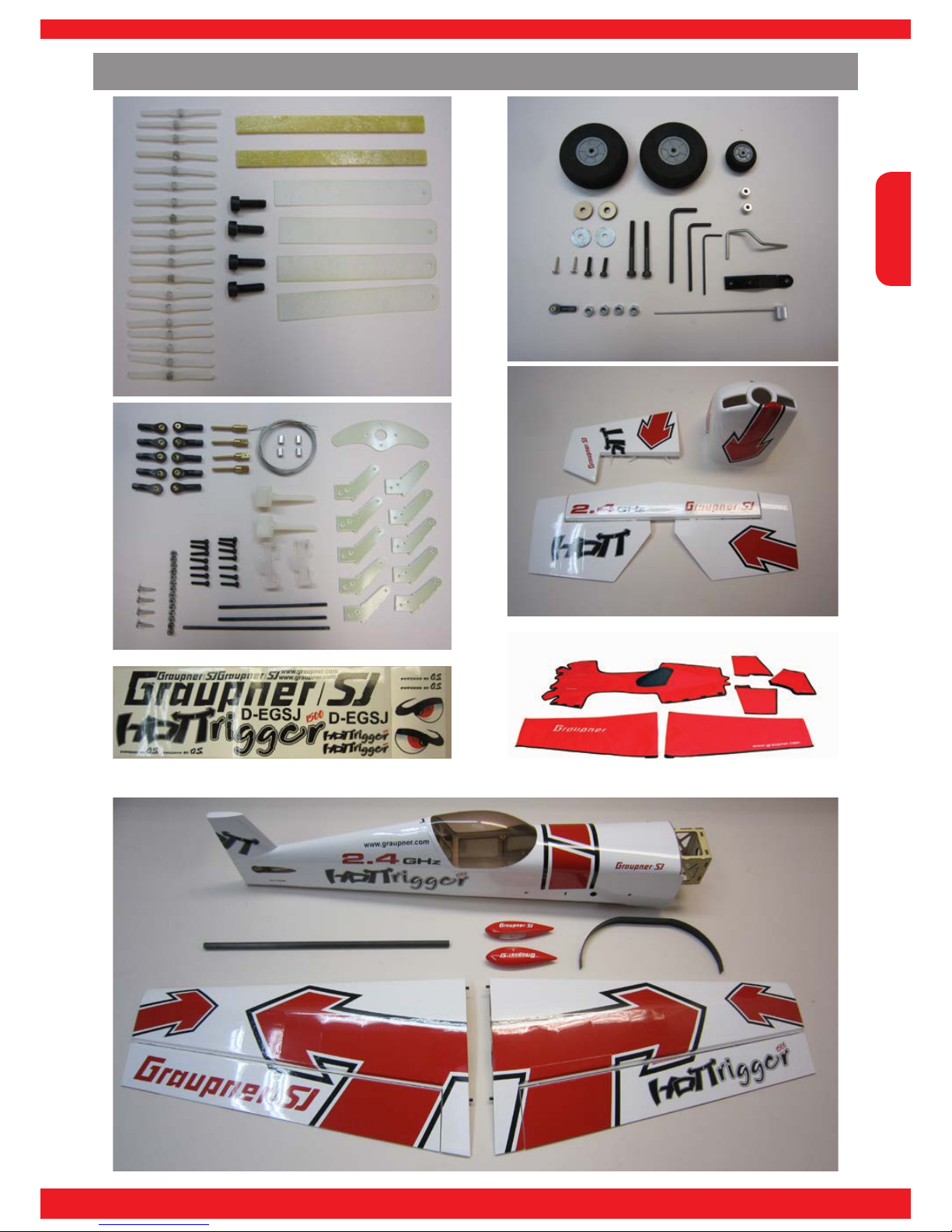
Parts List ......................................................................4
Kit contents ...................................................................5
Recommended accessories .........................................6
Recommended accessories - electric motor ................6
Adhesive .......................................................................6
Tools required ............................................................... 6
Symbols and their meaning ..........................................7
Warnings and safety notes ...........................................8
Manufacturer‘s declaration on behalf of GRAUPNER/
SJ GmbH ....................................................................12
Assembling the model ................................................13
Removing covering lm ..............................................13
Servo installation - general .........................................14
1. Information on installing servos ................................. 14
2. Servo installation ....................................................... 14
3. Fitting the rubber grommets ...................................... 14
4. Fitting the tubular brass spacers ............................... 14
5. Extending the servo lead ........................................... 15
6. Parking the servo leads ............................................. 15
Canopy .......................................................................16
Gluing the point-hinges ..............................................16
1. Information on gluing the point-hinges ...................... 16
2. Preparing the point-hinges ........................................ 16
3. Applying glue to the hinge holes ................................ 17
4. Inserting the point-hinges .......................................... 17
Installing the tailplane .................................................19
1. Aligning the tailplane ................................................. 19
2. Removing the lm from the joint surfaces ................. 20
3. Removing the lm from the joint surfaces ................. 21
4. Gluing the tailplane in place ...................................... 21
5. Preparing the elevator joiners ................................... 22
6. Gluing the elevator joiners ......................................... 22
7. Attaching the elevators .............................................. 23
Attaching the rudder to the n ....................................25
Attaching the rudder .................................................25
Installing the tailwheel assembly ................................26
Tailwheel bracket assembly ........................................... 26
4. Installing the tailwheel ............................................... 27
Installing the tailwheel bracket ...................................... 28
Tailwheel steering system ............................................. 28
Installing the undercarriage ........................................29
1. Installing the main undercarriage units ...................... 29
2. Preparing the wheel spats ......................................... 30
2. Fitting the wheel axles ............................................... 30
Installing the horns .....................................................32
Preparing the control horns ........................................... 32
Preparing the pushrods ................................................. 33
Preparing the servo output arms ................................... 34
Attaching the pushrods to the servo output arms .......... 34
Aileron and elevator ...................................................36
Installing the servos ....................................................... 36
Installing the servo output arms .................................... 37
Adjusting the pushrods .................................................. 37
Gluing the control surface horns ................................... 38
Rudder linkage ..........................................................39
Attaching the rudder cables ........................................... 39
Installing the rudder output arm ..................................... 41
Installing and replacing the batteries ..........................46
Installing the receiver..................................................47
General information ....................................................... 47
Wing root connection ..................................................... 47
Securing the receiver .................................................... 47
Aerial deployment .......................................................... 47
Installing the electric motor .........................................48
Preparing the cruciform motor mount ............................ 48
Fitting the stand-off pillars ............................................. 49
Installing the motor ........................................................ 49
Soldering the sockets to the speed controller ............... 50
Installing the speed controller .....................................51
Installing the spinner OMA-5020-490 .........................52
Installing the Cowl ......................................................54
Drilling the holes for the cowl retaining screws ............. 54
Applying the decals ....................................................56
Information on applying decals ...................................... 56
Slitting the decals over a hinge line ............................... 57
Model settings ............................................................58
Centre of Gravity: .......................................................... 58
Basic control surface travels: ........................................ 58
Attaching the wings to the fuselage ............................58
Using Planejama (aeroplane nightshirt) .....................59
Care and maintenance ...............................................60
Environmental protection notes ..................................60
Maiden ight ...............................................................60
Notes ..........................................................................61
Page 3

English
3
INNOVATION & TECHNOLOGY
Foreword
Many thanks for your decision to purchase the HoTTrigger, which is an aerobatic model of conventional all-wood construction. The HoTTrigger is a great aeroplane for modellers who already
have experience with powered models and wish to expand their skills, but it is also ideal for
more advanced pilots. The model is easily capable of standard and 3D aerobatics, and offers an
excellent performance. This means that you have acquired an aircraft which is ideal for practi-
sing aerobatic manoeuvres as well as simple fun ying, and all with ease of handling and little
effort. The model is very easy to rig: all you have to do is attach the wings to the fuselage using
two screws. The generous canopy opening ensures easy handling, and makes the model very
practical for everyday ying. The HoTTrigger can be completed with an electric power system
or a glow motor, and is prepared as standard for both versions. All you have to do is decide on
your preferred type of power, and acquire the appropriate accessories.
Attention!
It is essential to read right through the instructions before assembling and ying the model.
!
Approved usage
The HoTTrigger 1500 is designed to be used as a model aircraft. It is not suitable for any other
purpose.
This aerobatic machine is part of the new range of GRAUPNER/SJ all-wood model aircraft. These models are of particularly high quality, and have been developed and tested for you in-house.
Installation of the airborne RC components is simple and quick thanks to the very large fuselage
opening. To prepare the model for the air all you have to do is install the RC components and
power system, and carry out a few minor gluing and assembly procedures.
Model summary description
Wingspan approx. 1500 mm
Length approx. 1430 mm
Overall height approx. 360 mm
All-up weight approx. 3200 g
Specication
Page 4

English
4
Parts List
Pos. Description Quant. Material Dimensions in mm
1
Point-hinge 19 Plastic Ø 3 x 49
2
Fuselage 1 Wood
3
Tailplane 1 Wood
4
Elevator joiner 2 GRP 120 x 10 x 2
5
R.H. elevator 1 Wood
6
L.H. elevator 1 Wood
7
Rudder 1 Wood
8
R.H. wing panel 1 Wood
9
L.H. wing panel 1 Wood
10
R.H. aileron 1 Wood
11
L.H. aileron 1 Wood
12
Grubscrew 2 Steel M 3 x 3
13
Collet 1 Steel Ø 8 x 5,5 x Ø 2,5
14
Wire tailwheel unit 1 Steel Ø 2,5
15
Tailwheel bracket 1 Steel ca. 50 x 10 x 2
16
Tailwheel steering rod 1 Steel/alum.
17
Tailwheel 1 Plastic Ø 27 x 13 x 2,5
18
Mushroom-head allen screw 6 Steel M 3 x 12
19
Ball-link 11 Plastic M 2
20
Main undercarriage unit 1 Aluminium
21
Cheesehead allen screw 2 Steel M 3 x 12
22
R.H. wheel spat 1 GRP
23
L.H. wheel spat 1 GRP
24
Cheesehead allen screw 2 Steel M 4 x 40
25
Spacer ring 2 Wood Ø 16 x 5 x 2
26
Main wheel 2 Plastic Ø 50 x 19 x 4
27
Self-locking nut 4 Steel M 4
28
Washer 2 Steel Ø 16 x 5 x 1
29
Control surface horn 10 GRP
30
Cheesehead allen screw 13 Steel M 2 x 10
31
Self-locking nut 13 Steel M 2
32
Aileron pushrod 2 Steel M 2 x 70
33
Elevator pushrod 1 Steel M 2 x 85
34
Ring-screw 4 Brass M 2 x 20
35
Rudder servo output arm 1 GRP
36
Crimp sleeve 4 Aluminium 5 x 3 x 4
37
Linkage cable 1 Steel Ø 0,5 x 1500
38
Cheesehead allen screw 4 Steel M 5 x 15
39
Drilling template 4 Felt 100 x 15 x 0,2
40
Cowl 1 GRP
41
Canopy 1 Plastic
42
Wing joiner tube 1 CFRP Ø 15 x 550
43
Retaining screw 1 Plastic 1/4“ x 50
44
Planejama (protective bags) 1 set Textile
Page 5
English
5
INNOVATION & TECHNOLOGY
Kit contents
Page 6

English
6
Recommended accessories
Adhesive
Tools required
Quant. Description No.
1 Gr. HoTT mx-16 8-channel computer system 33116
4
DES 708 BB MG servo 7946
1 GR 16 receiver 33508
2 100 mm extension lead 3935.11
1 320 mm extension lead 3935.32
1 White plastic spinner, 57 mm Ø 1112.57
1 Hook-and-loop strap, length 320 mm 1587
1
DES CFRP heavy-duty servo output arm 7907.2
1 Low-viscosity cyano-acrylate (thin cyano) 5822
1 Activator spray 953.150
1 UHU-Schraubensicher (thread-lock uid) 952
1 UHU-Plus endfest 300 (slow-setting epoxy) 950.43
1 UHU-schnellfest (fast-setting epoxy) 962
1 Silicone damper oil, 150 cps / 60 ml 95401
Description No.
Scalpel 982
Water pump pliers
Scissors
Cross-point screwdriver
1.2 / 1.9 / 5 / 6.4 mm drill bits
14 mm A/F open-ended spanner
4.5 mm socket spanner
1 O.S. OMA-5020-490 6626
1 Brushless Control +T 70 G 3,5 33770
1 V-MAXX 5/4200 18.5 V G3.5 LiPo, 45C 9740.5
1 Electric propeller, 15 x 8” 1326.15x8
2 Hook-and-loop tape, 100 mm 3368.1
1 Stand-off pillar, length 44.5 mm 2269.44,5
Recommended accessories - electric motor
Page 7
English
7
INNOVATION & TECHNOLOGY
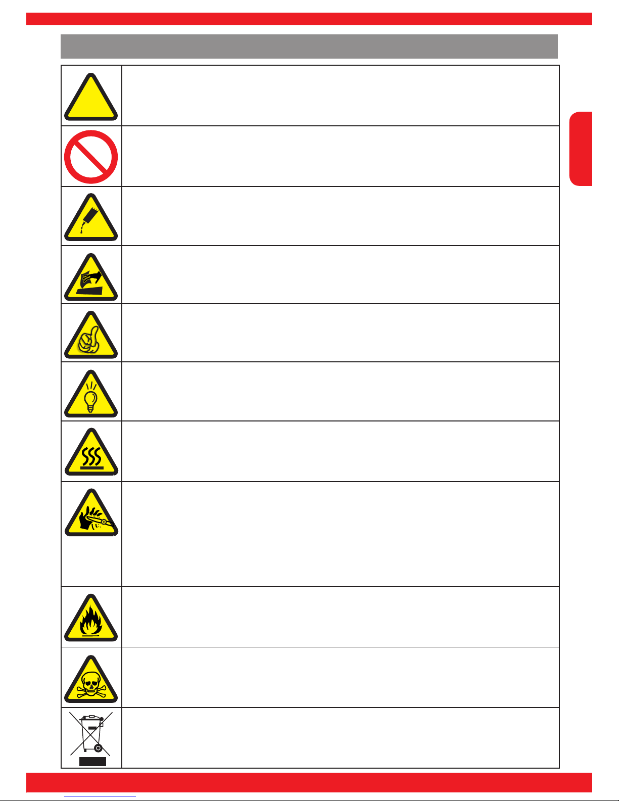
Symbols and their meaning
Attention!
This symbol alerts you to the following notes which the user must observe. Neglecting this
information may have an adverse effect on the system’s proper function and the safety of the
operator.
Warning!
This symbol alerts you to prohibited actions which the user must always observe. Neglecting
these warnings may have an adverse effect on the system’s proper function and the safety of
the operator.
Note regarding adhesives!
This symbol calls attention to the particular adhesive which is to be used in the following procedure in order to obtain a sound joint, or to secure the components or screws.
Care and maintenance!
This symbol calls attention to notices about care of the model which must absolutely be observed to ensure its long service life.
Note!
This symbol alerts the user to information which must always be observed in order to ensure
the safe operation of the device.
Tip!
This symbol alerts you to hints and tips during the model’s construction which help to avoid
problems and potential damage, and provide information on solving possible problems.
Warning: hot surfaces!
This symbol calls attention to injury risks which arise if you touch hot surfaces. Neglecting
these warnings may lead to serious injury.
Rotating power unit!
This symbol calls attention to the injury risks associated with operating a propeller which must
absolutely be observed by the user! Any disregard for the adjacent notices can lead to imbalance of the propeller, can se-verely damage the model and can produce most severe injuries
for persons in the vicinity as a consequence of hurled parts.
This symbol calls attention to the injury risks associated with operating a propeller which must
absolutely be observed by the user! Any disregard for the adjacent notices can lead to severe
injuries for the operator.
Inammable!
This symbol calls attention to the following information, which the user must always observe.
Neglecting these warnings incurs a risk of explosion and re.
Warning: toxic substances!
This symbol calls attention to the following information, which the user must always observe.
Neglecting these warnings incurs a risk of poisoning.
Disposal notes
This symbol calls attention to information regarding specic materials or products, which
must be observed when disposing of these items.
!
Page 8
English
8
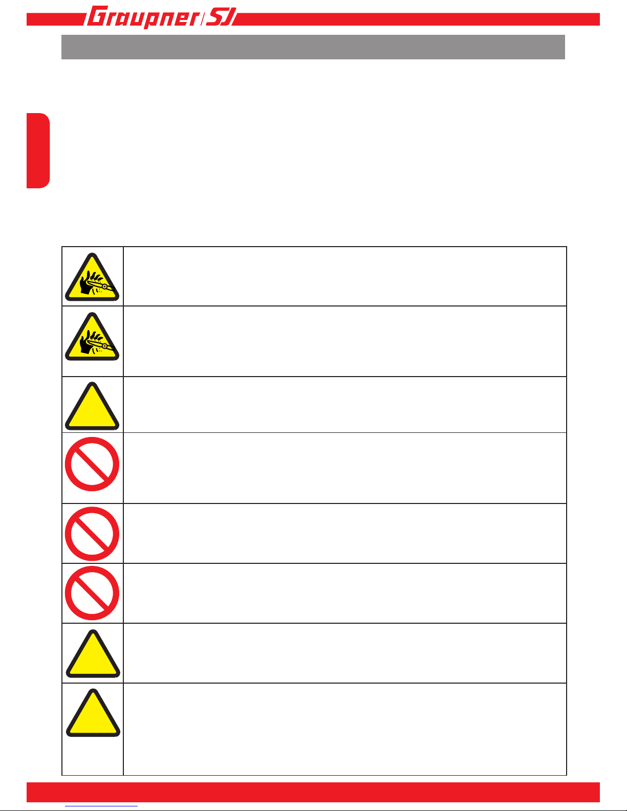
Warnings and safety notes
Attention!
Never reach into a running propeller or attempt to hold the propeller by hand when it is operating. This leads to hand injuries. Rotational forces can readily cause the propeller to get out of
control.
Attention!
Never put objects/foreign materials into a running propeller. Always ensure that objects/foreign
materials can-not get into the propeller when it is running. If this does happen, the propeller‘s
sudden imbalance can cause heavy damage to the model. Persons in the vicinity can be severely injured by parts hurled through the air.
Attention!
Never dwell in front or back of a propeller. Improper assembly or unforeseen circumstances
can cause the propeller to come off of its shaft. Stop the propeller if unusual noises are heard.
Warning!
The propeller must be securely attached. Do not direct the propeller toward persons or animals, do not test the propeller in the hand. Never dwell in front of a propeller. Unforeseen
circumstances can cause the propeller to come off of its shaft. Persons in the vicinity can be
severely injured by parts hurled through the air.
Warning!
Do not touch any part of the drive train (i.e. motor + propeller + shaft) while it is operating as
this can lead to injuries. Allow the motor, shaft, regulator and battery time to cool off after operation before touching any of these parts!
Warning!
Operating the model while under the inuence of medication, alcohol, drugs, etc. is forbidden.
Attention!
Any deviation from the model‘s instructions can have an effect on the model‘s functionality
and operational safety. This must be avoided under all circumstances.
Attention!
The operator of a RC model must be aware of the legal stipulations before putting a RC model
into operation because a RC model is subject to applicable laws. Applicable laws are always
to be followed in every case. In this respect, pay attention to the laws applicable in the given
country. Before operating the model for the rst time, check if your private liability insurance
provides coverage for RC models of this type. If this is not the case, obtain special liability
insurance coverage for RC models.
!
!
!
This is a model that – together with appropriate accessories – can become a functional RC
model. GRAUPNER/SJ cannot monitor adherence to the assembly and operating instructions
for the model nor can GRAUPNER/SJ supervise the installation, operation or maintenance of
the model and its components. There-fore GRAUPNER/SJ accepts no liability whatsoever for
losses, damage or costs that arise from improper op-eration, improper behavior or which are
associated with same in any manner. Unless mandated by prevail-ing law, the obligation of the
GRAUPNER/SJ company to provide damage compensation arising from the use of the model,
regardless of the grounds, is excluded (this exclusion includes personal injury, death, damage to
buildings or structures as well as sales and business losses, consequential damage for busi-
ness inter-ruption or other direct and indirect consequential damages).
Total liability under all circumstances and in each case is limited to the amount actually paid for
this model.
Page 9
English
9
INNOVATION & TECHNOLOGY
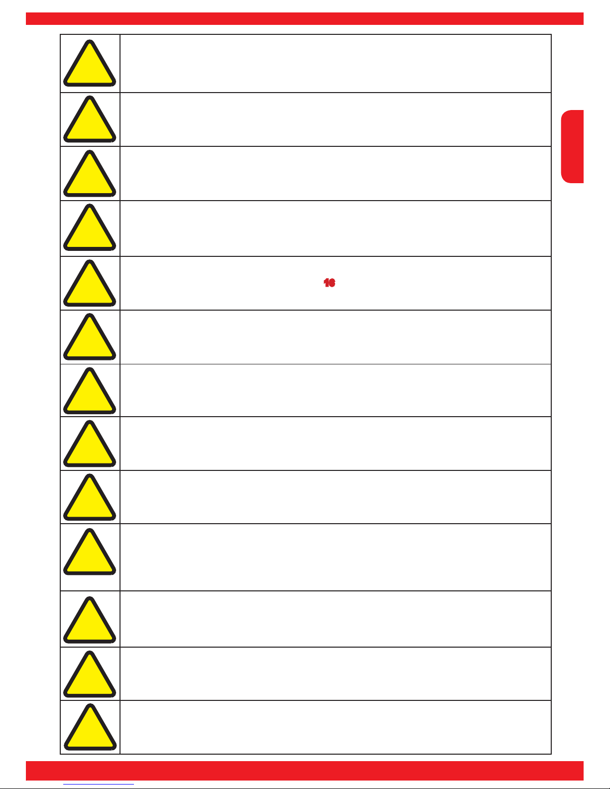
Attention!
RC models are very demanding and potentially dangerous objects, and call for a high level of
knowledge and expertise from the operator, together with a sense of responsibility.
Attention!
Adhesives and paints contain solvents which can be injurious to health. It is important to heed
the manufacturer’s instructions and warnings.
Attention!
The model may only be operated with accessories which we recommend as otherwise functionality cannot be guaranteed.
Attention!
The commissioning and operation of the model is solely at the risk of the operator. Only cautious, considered handling during operation of the model will prevent personal injuries and
property damage.
Attention!
This model is not suitable for children under 16 years of age.
Attention!
Pay attention to the potential dangers associated with the tools that are used.
Attention!
Comply with the recommendations and notices associated with the remote control set and
accessories.
Attention!
Before operating the model, check it for reliable response to the remote control unit and all
plug-in connections for secure connection.
Attention!
Never attempt to recharge any primary cell batteries used as a power supply. Only rechargeable (i.e. secondary cell) batteries may be charged.
Attention!
The remote control unit‘s effective range must be checked prior to operation of the model. To
check this, switch the model on then walk with it away from the transmitter as far as about 100
m while a helper operates various controls on the transmitter. At this distance it must be possible to operate all model functions without any problem.
Attention!
Pay attention to radio devices or transmitters which could substantially affect the model‘s
functionality. Try to ensure that such devices are not operated in the vicinity while the model is
being operated.
Attention!
Batteries must never be short-circuited or come into direct contact with water.
Attention!
Never endanger yourself or others in an attempt to recover the model.
!
!
!
!
!
!
!
!
!
!
!
!
!
Page 10
English
10
Attention!
Take care with loose clothing such as scarves, loose shirts etc. Flapping cloth can easily be
sucked into the area of the propeller and then get tangled in the blades.
Attention!
If there are passers-by or spectators at your ying site, make sure that they are aware of the
dangers inherent in your activity, and insist that they keep a safe distance away (at least 5 m
behind the plane of the propeller).
Attention!
Model aircraft should only be own in “normal” weather conditions, i.e. a temperature range
of -5° to +35° C. More extreme temperatures can lead to changes in battery capacity, material
characteristics and other unwanted effects.
Attention!
If your model is powered by a motor or engine, it is important to observe the safety notes provided by the manufacturer of the power plant.
Attention!
Before and after every ight check the model and all parts attached to it - e.g. propellers, control surface linkages, control surfaces etc.) for possible damage. Do not y the model again
until you have corrected any defects.
Attention!
Adhesives and paints contain solvents which may be hazardous to health under certain circumstances. Read and observe the notes and warnings supplied by the manufacturer of these
materials.
Attention!
Never y over or towards other people.
Attention!
During take-off and landing procedures the runway must be free of unauthorised persons and
movable obstacles.
Attention!
Watch the aeroplane constantly while it is in the air. Models must always give way to full-size
aircraft.
Attention!
Never y the model from public roads, squares, schoolyards, parks and public playing elds. It
is your responsibility to keep the model under full control at all times.
Attention!
All model yers should behave in a manner which avoids endangering or interfering with public safety and order. Never act in any way which will disturb other yers and jeopardise safe,
orderly ying at the site.
Attention!
As operator of this model aircraft you bear sole responsibility for its safe operation, The only
way to avoid personal injury and property damage is to operate your model cautiously and
conscientiously.
!
!
!
!
!
!
!
!
!!!
!
Page 11
English
11
INNOVATION & TECHNOLOGY
Attention!
If there are passers-by or spectators at your ying site, make sure that they are aware of the
dangers inherent in your activity, and insist that they keep a safe distance away (at least 5 m
behind the plane of the propeller).
Attention!
This aeroplane is highly pre-fabricated and can be completed in a very short time. However,
the work which you have to carry out is important and must be done carefully. The model will
only be strong and y well if you complete your tasks competently - so please work slowly and
accurately.
Attention!
If your model is powered by a motor or engine, it is important to observe the safety notes provided by the manufacturer of the power plant.
Attention!
Before and after every ight check the model and all parts attached to it - e.g. propellers, control surface linkages, control surfaces etc.) for possible damage. Do not y the model again
until you have corrected any defects.
Attention!
Adhesives and paints contain solvents which may be hazardous to health under certain circumstances. Read and observe the notes and warnings supplied by the manufacturer of these
materials.
Attention!
Please don’t misunderstand the purpose of these notes. All we want to do is bring to your attention the many dangers and hazards which can arise if you lack knowledge and experience,
or work carelessly or irresponsibly. If you take reasonable care, model ying is a highly creative, instructive, enjoyable and relaxing pastime.
Attention!
It is important that your shoes should not slip when you are dealing with the motor or engine.
The model must also be rmly secured.
Note!
When the model is not in use, remove the ight battery from the model, and the dry or rechargeable cells from the transmitter.
Note!
Do not subject the model to severe humidity, heat, cold or dirt.
Note!
Secure the model and transmitter when transporting them, otherwise they could slide about
and be damaged.
Care!
Clean the model and the transmitter using suitable cleaning materials only; we recommend a
lint-free cloth. Never use chemical cleaning agents, solvents, methylated spirit, white spirit or
similar.
Attention!
According to the new regulation of §103 Paragraph 3 of the LuftVZO (German Aviation Approvals Ofce), all model aircraft - whether slow-yer, park-yer, glider, or model aircraft propelled
by any form of power plant - must be insured before the model is operated. If you are not sure
about this, please ask at your local model shop where the staff will be glad to advise you.
These safety notes must be kept in a safe place. If you ever dispose of the model, be sure to
pass them on to the new owner.
!
!
!
!
!
!
!
!
Page 12

English
12
Contents of the manufacturer’s declaration:
If material defects or manufacturing faults should arise in a product distributed by us in the Fe-
deral Republic of Germany and purchased by a consumer (§ 13 BGB), we, Graupner/SJ GmbH
D-73230 Kirchheim/Teck, Germany, acknowledge the obligation to correct those defects within the
limitations described below.
The consumer is not entitled to exploit this manufacturer’s declaration if the failure in the usability
of the product is due to natural wear, use under competition conditions, incompetent or improper
use (including incorrect installation) or external inuences.
This manufacturer’s declaration does not affect the consumer’s legal or contractual rights regar-
ding defects arising from the purchase contract between the consumer and the vendor (dealer).
Extent of the guarantee
If a claim is made under guarantee, we undertake at our discretion to repair or replace the defective goods. We will not consider supplementary claims, especially for reimbursement of costs
relating to the defect (e.g. installation / removal costs) and compensation for consequent damages
unless they are allowed by statute. This does not affect claims based on legal regulations, especially according to product liability law.
Guarantee requirements
The purchaser is required to make the guarantee claim in writing, and must enclose original proof
of purchase (e.g. invoice, receipt, delivery note) and this guarantee card. He must send the defective goods to us at his own cost, using the following address:
Graupner/SJ GmbH, Serviceabteilung,
Henriettenstr.96, D 73230 Kirchheim/Teck
The purchaser should state the material defect or manufacturing fault, or the symptoms of the
fault, in as accurate a manner as possible, so that we can check if our guarantee obligation is
applicable.
The goods are transported from the consumer to us and from us to the consumer at the risk of the
consumer.
Duration of validity
This declaration only applies to claims made to us during the claim period as stated in this declaration. The claim period is 24 months from the date of purchase of the product by the consumer from
a dealer in the Federal Republic of Germany (date of purchase). If a defect arises after the end of
the claim period, or if the evidence or documents required according to this declaration in order to
make the claim valid are not presented until after this period, then the consumer forfeits any rights
or claims from this declaration.
Limitation by lapse of time
If we do not acknowledge the validity of a claim based on this declaration within the claim period,
all claims based on this declaration are barred by the statute of limitations after six months from
the time of implementation; however, this cannot occur before the end of the claim period.
Applicable law
This declaration, and the claims, rights and obligations arising from it, are based exclusively on the
pertinent German Law, without the norms of international private law, and excluding UN retail law.
Manufacturer‘s declaration on behalf of GRAUPNER/SJ GmbH
Page 13
English
13
INNOVATION & TECHNOLOGY
Assembling the model
Attention!
It is important to observe the sequence of procedures described in these building instructions.
Attention!
Before you start assembling the model we recommend that you run a lm iron over the covering lm to ensure that it is taut, as uctuations in temperature and humidity may have
caused creases, and the lm may have come loose from the wood in places. This is important,
because in some areas the lm has to be removed, and the remaining lm would then shrink
uncontrollably when ironed down again.
!
!
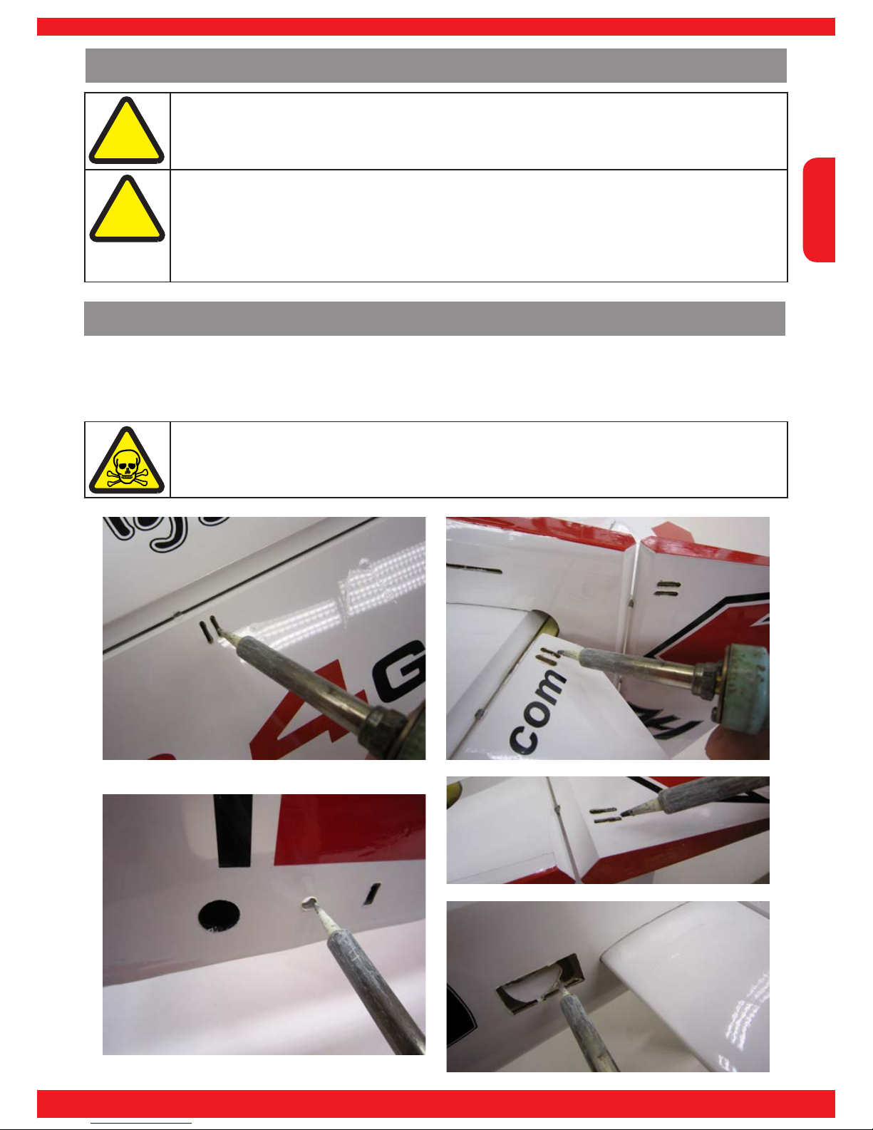
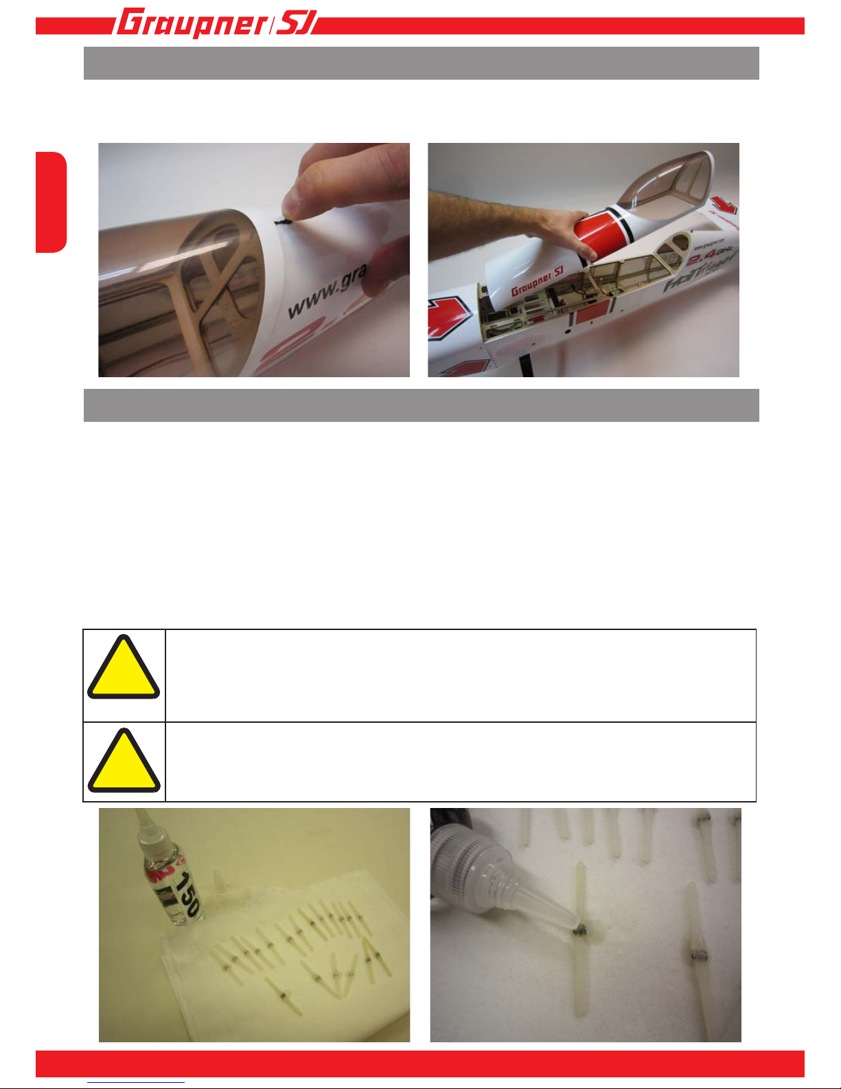
Use a hot soldering iron to melt away the covering lm over the holes for the wing joiner tube, incidence pegs,
retaining screws, control surface horns and servo leads. Use your ngertips to locate the openings under the lm.
Removing covering lm
Attention!
This stage should be carried out in a well ventilated room, to avoid directly breathing in fumes.
Page 14
English
14
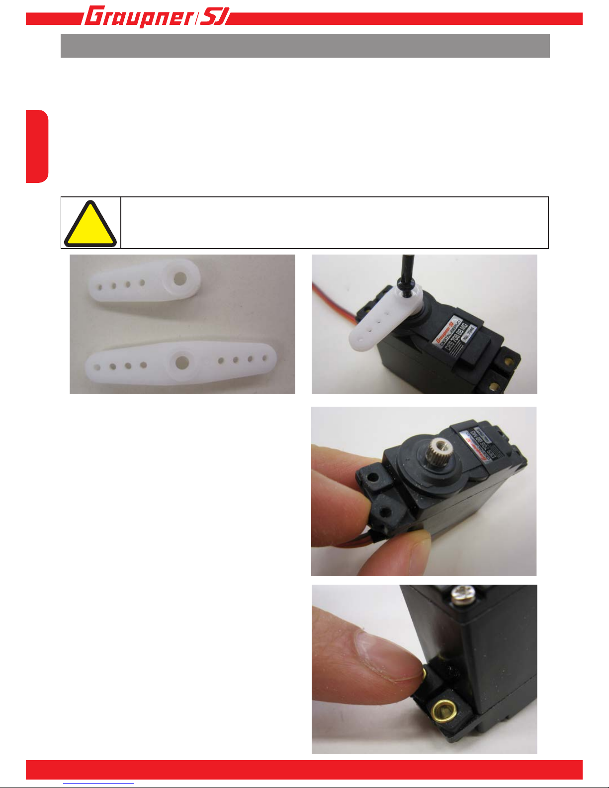
Attention!
Avoid damaging the raised ange of the servo output arm, otherwise the arm could fail in
ight, leaving the model uncontrollable.
!
2. Servo installation
Cut down the servo output lever as shown in the photo. Centre the servo from the transmitter using a new model
memory. Push the lever onto the output shaft.
3. Fitting the rubber grommets
Push the rubber grommets into the servo mounting lugs.
Servo installation - general
1. Information on installing servos
The same procedure is employed for preparing and tting all the servos. The following steps should be carried
out for each servo which is to be installed, using the parts supplied in the servo’s accessory pack. Variations from
the standard procedure - such as tting different servo output arms, and changing the position of the arms on the
servos - are explained in the relevant stages, and shown in the pictures of the installed servos.
4. Fitting the tubular brass
spacers
Push the brass spacers into the rubber grommets from
underneath.
Page 15
English
15
INNOVATION & TECHNOLOGY
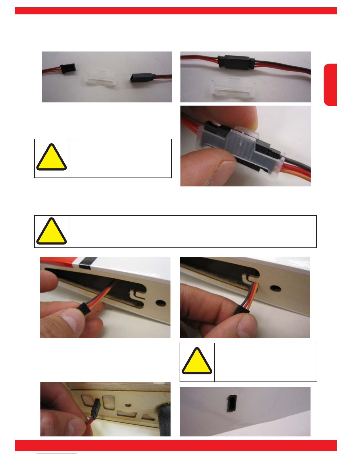
5. Extending the servo lead
If a servo extension lead is used, it must be secured using one of the clips supplied. First insert the servo lead
plug into the socket on the extension lead.
Attention!
Check that the clip engages fully,
otherwise the servo could become
disconnected in ight, leaving the
model uncontrollable.
!
Push the clip over the plastic plug / socket housings.
6. Parking the servo leads
The aileron servo leads can be ‘parked’ in slots in the wing root; this prevents the nuisance of the leads falling
inside the wing.
Attention!
The slots are only intended for use when the wings are in storage. Disengage the leads from
the slots before assembling the model, otherwise the wings will not t correctly against the
fuselage; using force could damage the slotted ribs.
!
The socket is tted in the slot in the fuselage side,
working from the inside, and glued in place using
thick cyano; it must nish ush with the outside of the
fuselage.
Attention!
Don’t allow glue to run inside the
socket, as this will soil the contacts,
and the connector will have to be
replaced.
!
Page 16
English
16
Canopy
Slide the canopy latch towards the tail and hold it in that position while you raise the rear end of the canopy and lift
it off.
Gluing the point-hinges
Attention!
Ensure that the oil only contacts the pivot of the point-hinge (1), and that no oil gets onto the
part of the hinge which is to be glued, otherwise the hinge might not be securely xed in the
hole. In this case the control surface could come loose in ight and render the model uncontrollable.
Attention!
Take care to keep the oil off your ngers, as this could transfer it to the joint areas of the hinge. Wash your hands after handling the oil to prevent unwanted transfer.
!
!
2. Preparing the point-hinges
Apply a drop of 150 cps silicone damper oil or similar to the pivot of the point-hinge (1) to protect it from excess
glue. Lay a strip of paper towel (kitchen paper) under the point-hinge (1) to absorb any excess oil.
1. Information on gluing the point-hinges
All the point-hinges (1) should be prepared and installed in the same manner. Follow the procedure described for
each hinge at the appropriate juncture. Complete the task for one sub-assembly at a time, e.g. rst one wing and
aileron, then the next, and so on. Any deviations from the standard procedure (e.g. for the elevators) are
explained at the appropriate point in the instructions, or are shown in the pictures of the point-hinges (1) when they
are tted.
Page 17
English
17
INNOVATION & TECHNOLOGY
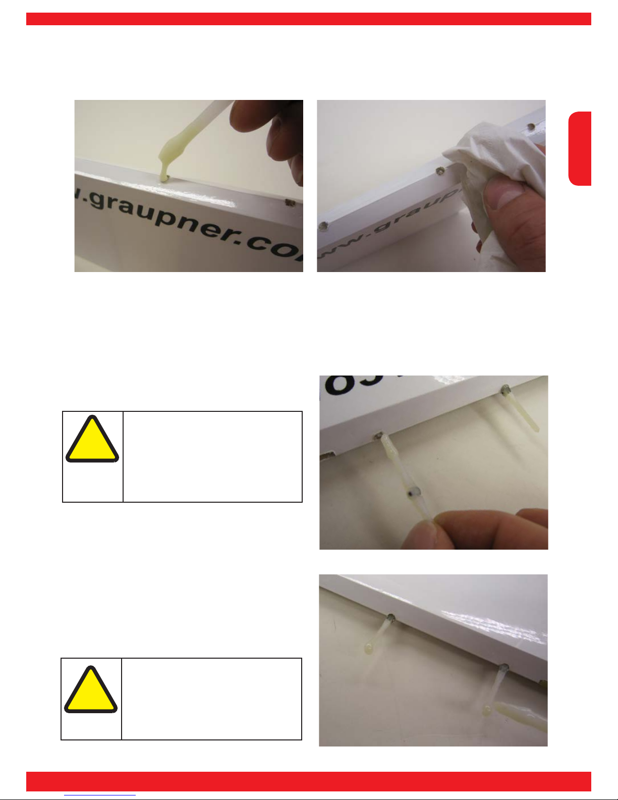
3. Applying glue to the hinge holes
The point-hinges (1) are glued in place using UHU-Plus Endfest 300 (slow-setting epoxy). Apply a little glue to each
hole in the control surface. If glue gets onto the surface adjacent to the hole, it can be removed by wiping with a
piece of kitchen paper dipped in methylated spirit.
4. Inserting the point-hinges
Apply a little adhesive to the rst third of the point-hinge (1), and twist the hinge into the hole. If you have used
the correct quantity of glue, the adhesive will be distributed along the length of the hinge and glue it to the control
surface over the full length of the hole. Push the point-hinge (1) into the hole to the point where the pivot axis is
located about 1 mm outside the leading edge of the control surface.
Attention!
Take care that no glue gets into the
pivot and jams the point-hinge (1), as
this might prevent the hinge rotating
when the glue has cured; the control
surface would then no longer move in
either direction.
!
Attention!
Take care not to apply too much glue,
as this would cause the excess to be
forced out of the hole and into the
pivot area of the point-hinge (1).
!
Apply a little adhesive to the rst third of the point-hinge
(1) and the hole in the mating part of the xed panel, as
described in section 3. Applying glue to the hinge
holes.
Page 18
English
18
Push the point-hinges (1) attached to the control surface into the holes in the xed panel or wing - depending on
the sub-assembly you are currently working on. Ensure that the colour scheme on the two panels
lines up correctly. Offer up the control surface, holding it at an angle at the pivot axis, and push the point-
hinges (1) one by one into the holes in the xed panel.
Attention!
This procedure is very important, and must be carried out with the greatest care, because there is a real risk of epoxy running into the pivot points and jamming the hinges. When the glue
has cured, the hinges will then be impossible to move, and the control surface will not deect.
Attention!
Dip a piece of kitchen paper into methylated spirit and use it to wipe away excess epoxy from
the surface of the components.
!
Now push the control surface towards the xed panel until the hinge pivots are just visible. Repeatedly move the
control surface to both extremes of travel to allow the point-hinges to settle themselves into the correct position.
Temporarily x the control surface to the xed panel
with paper masking tape to ensure that it cannot shift.
Allow the epoxy to set hard, then remove the tape and
move the control surface in both directions. You may
hear a slight cracking sound as any excess glue at the
hinge pivots fractures; this is not a problem, unless the
hinge is completely jammed with glue.
!
Page 19
English
19
INNOVATION & TECHNOLOGY
Installing the tailplane
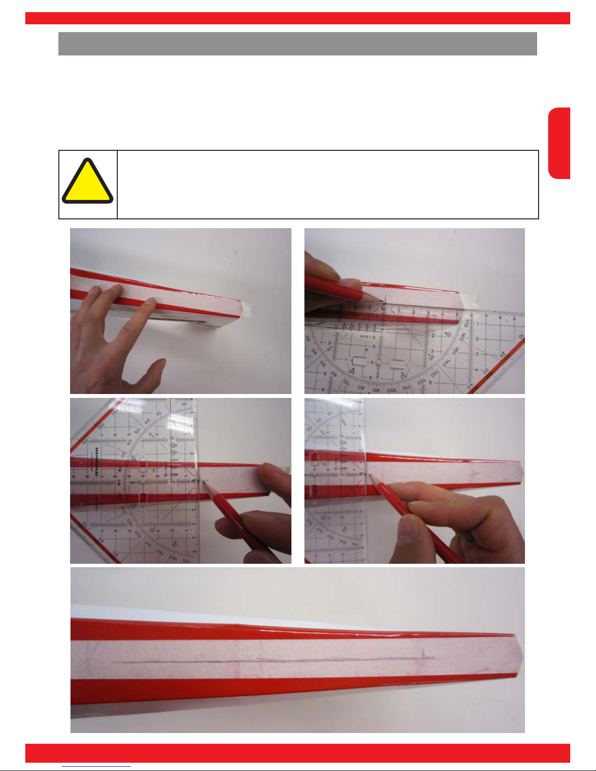
1. Aligning the tailplane
Apply a strip of paper masking tape to the underside of the fuselage (2) to protect the underlying lm. Draw a
centreline on the tape, on which a setsquare can be placed in order to help you align the tailplane (3). First mark
the end of the tailplane (3) at which the setsquare will be positioned later.
Attention!
This procedure must be carried out with the greatest care, otherwise the tailplane may be installed at an angle. This will cause the model to veer off to one side when you apply an elevator
command, and it will be difcult to y in a straight line.
!
Page 20

English
20
Attention!
Take care to set the tailplane (3) exactly ‘square’ in the fuselage before marking the surfaces,
otherwise you could easily remove too much lm and leave the wood exposed, where it would
be subject to weathering. This could lead to material fatigue and structural failure, leaving the
model uncontrollable.
!
2. Removing the lm from the joint surfaces
The covering lm over the joint surfaces of the tailplane (3) must rst be removed: slide the tailplane (3) through
the slots in the fuselage (2), and set it central; it must also be at 90° to the fuselage centreline. Draw a line on the
tailplane on both sides of the fuselage (2), top and bottom, to mark the area of lm to be removed.
Page 21

English
21
INNOVATION & TECHNOLOGY
4. Gluing the tailplane in place
Slide the tailplane (3) into the slot in the fuselage (2), and set it exactly central. It must project by the same
dimension on both sides, and be at an angle of 90° to the fuselage centreline, so that the area from which the lm
has been removed is completely hidden inside the fuselage (2).
Attention!
Ensure that the tailplane (3) is the right way up in the slots in the fuselage (2), as shown in the
picture.
Note!
Use thin cyano, No. 5822, for this joint. Fitting a syringe needle allows you to apply the glue
directly to the wood and the joint lines to ensure a sound joint.
!
3. Removing the lm from the joint surfaces
Run the tip of a soldering iron along the marked lines, using a steel ruler as a guide, and remove the lm between
the two cuts.
Attention!
Just allow the tip of the soldering iron to glide over the lm. Don’t apply excessive pressure,
as this could damage the wood underneath; the tailplane could then snap off at the fuselage,
leaving the model uncontrollable.
Attention!
Carry out this procedure in a well ventilated room to avoid directly breathing in the fumes.
!
Page 22

English
22
5. Preparing the elevator joiners
Sand both sides of the elevator joiner (4) using 100-grit abrasive paper, to ensure that the glue adheres strongly
to the surfaces.
6. Gluing the elevator joiners
The elevator joiners (4) must be glued together before the elevators (5) are attached by their hinges. This is
important, as the joiners and hinges must be aligned while the glue is soft, to ensure that
the elevators work correctly. Use the same adhesive as specied for the hinges.
Attention!
Ensure that the larger faces of the elevator joiners (4) are glued together, as the angled edge of
the joiner forms an extension of the elevator leading edge.
!
Apply a thin, even layer of epoxy to one of the
mating faces, and place the two joiners (4) together.
Press them together lightly, and check that their
edges line up ush.
Place the elevator joiner (4) to one side for a
moment, and continue with point 6. Attaching
the elevators.
Page 23

English
23
INNOVATION & TECHNOLOGY
7. Attaching the elevators
Glue the point-hinges (1) in one of the elevators (5 or 6) as described in the section entitled Gluing the pointhinges (1). Apply epoxy to the slot for the elevator joiner (4). Wipe off excess resin using kitchen paper and
methylated spirit.
Push the elevator joiner (4) into the slot. Wipe off
excess glue using paper towel and methylated spirit.
Apply glue to the point-hinges (1) and the hinge holes in the tailplane (3).
Attention!
It is important to t the tailplane (3)
in the slot with the top surface facing
up, as shown in the picture.
!
Page 24

English
24
Attach one elevator (5 or 6) to the tailplane by means
of the point-hinges (1) and the elevator joiner (4).
Repeat the procedure for the second elevator panel
(5 or 6).
Attach the second elevator (5 or 6) to the tailplane (3)
using the point-hinges (1) and the elevator joiner (4).
Push both elevators (5 and 6) towards the tailplane as far as the pivot axis of the point-hinges (1). Repeatedly
move the elevators up and down to allow the point-hinges (1) to settle in the correct position.
Attention!
Deect both elevators up and down and check that they move simultaneously and evenly, to
ensure that the hinges in both panels (5 and 6) are positioned equally; if the pivot axes are
different, the elevators will not be able to deect accurately.
!
Page 25

English
25
INNOVATION & TECHNOLOGY
Temporarily x the elevators (5 and 6) to the tailplane with paper masking tape to prevent them shifting, then use
a screwdriver to push the elevator joiner into the elevators (5 and 6) as far as it will go. Wipe off excess epoxy
using methylated spirit on a piece of paper towel.
Attaching the rudder to the n
Glue the point-hinges (1) into the rudder (7) as described in the section entitled Gluing the point-hinges
(1). Wipe off excess glue with paper towel and methylated spirit.
Attaching the rudder
Glue the point-hinges (1) into the wings (8 and 9) and the ailerons (10 and 11) as described in the section
entitled Gluing the point-hinges (1). Wipe off excess glue with paper towel and methylated spirit.
Page 26

English
26
Installing the tailwheel assembly
Remove the grubscrew (12) from the tailwheel steering
rod (16), and slip the steering rod (16) onto the wire
tailwheel unit (14).
Slip the tailwheel bracket (15) onto the wire tailwheel
unit (14).
Tailwheel bracket assembly
Remove the grubscrew (12) from the collet (13), then t
the collet (13) on the wire tailwheel unit (14).
Page 27

English
27
INNOVATION & TECHNOLOGY
4. Installing the tailwheel
Slip the tailwheel (17) onto the wire unit (14), and secure it with the collet (13) and grubscrew (12).
Note!
Use UHU thread-lock uid, No. 952, to prevent the grubscrew (12) working loose.
Position the tailwheel steering rod (16) on the wire
tailwheel unit (14) in such a way that part (14) is
exactly at 90° to the steering rod (16). Tighten the
grubscrew (12) in the collet.
Note!
Use UHU thread-lock uid, No. 952, to
prevent the grubscrew (12) working
loose.
Locate the collet (13) which you tted rst, and slide
it along the wire until it rests against the tailwheel
bracket (15). Tighten the grubscrew (12).
Note!
Use UHU thread-lock uid, No. 952, to
prevent the grubscrew (12) working
loose.
Page 28

English
28
Installing the tailwheel bracket
Fix the tailwheel bracket (15) to the fuselage using the retaining screws (18).
Glue the ball-link (19) into the rudder (7) using thick
cyano-acrylate.
Tailwheel steering system
Mark a point about 20 mm from the end of the tailwheel steering rod (16) on the centreline of the rudder (7).
Use a 5 mm bit to drill a hole for the ball-link (19) which acts as a link between the rudder and the tailwheel.
Note!
Use UHU Schraubensicher (thread-lock uid) No. 952 to secure the screws (18).
Slip the ball-link (19) onto the tailwheel steering rod (16) and push it into the hole in the rudder (7).
Page 29

English
29
INNOVATION & TECHNOLOGY
1. Installing the main undercarriage units
Invert the fuselage (2) and lay it on the bench prior to attaching the undercarriage.
Installing the undercarriage
Place the main undercarriage unit (20) in the recess in
the fuselage, and secure it with the retaining screws
(21).
Note!
Use UHU Schraubensicher (threadlock uid) No. 952 to secure the
screws (21).
Page 30

English
30
2. Fitting the wheel axles
Fit the screw through the enlarged hole in the wheel
spat (22, 23), then slip the spacer ring (25) on the screw
(24) inside the spat.
Fit the wheel (26) onto the screw (24).
Screw the self-locking nut (27) onto the screw (24) to
the point where the screw (24) projects out of the selflocking nut (27) by about 2 mm.
2. Preparing the wheel
spats
Open up the hole in the outside of the wheel spats (22,
23) using a 6.4 mm Ø drill, then use a round le to open
up the hole slightly to clear the head of the screw (24);
the screw-head should be a close t in the hole.
Attention!
Take care to produce one left-hand
and one right-hand wheel spat.
!
Page 31

English
31
INNOVATION & TECHNOLOGY
Slip the washer (28) onto the projecting end of the
screw.
Tighten the screw fully into the self-locking nut (27),
ensuring that the wheel (26) still rotates. The head of
the screw should now be located in the enlarged hole in
the wheel spat (22, 23).
The wheel spat (22, 23) is xed to the main
undercarriage unit (20) using the installed screw
(24): slip the screw (24) through the hole in the main
undercarriage unit (20).
Fit a further self-locking nut (27) on the screw so
that the spat (22, 23) can be xed to the main
undercarriage unit (20) using the screw. Lock the two
self-locking nuts (27) against each other.
Attention!
Ensure that both wheels (26) rotate
smoothly, otherwise the model will
not run straight on the runway.
!
Page 32

English
32
Installing the horns
Preparing the control horns
All the control surface horns (29) are prepared and
glued in place using the same procedure. Follow these
steps for each horn (29) which has to be installed on the
model. Any variations from this procedure are explained
in the instructions at the appropriate point, or can be
seen in the pictures.
Sand the joint areas on both sides of the horns (29)
using 100-grit abrasive paper, to ensure that the glue
adheres strongly to the components.
Slip the screw (30) through the horn.
Fit the ball-link (19) onto the screw (30).
Page 33

English
33
INNOVATION & TECHNOLOGY
Attach the second horn (29) to the screw (30).
Tighten the self-locking nut (31) on the screw (30).
Prepare a total of ve control surface horn assemblies
using this procedure. For aesthetic reasons it is best
to prepare two right-hand and three left-hand horn
assemblies; this is accomplished by tting the retaining
screws through the control surface horns (29) from
left or right as appropriate. The horns should then be
installed with the screw-head facing out. This also
makes maintenance easier, e.g. at the elevators.
Preparing the pushrods
Screw the pushrods (32, 33) and ring-screws (34) into the ball-links (19) by about 5 - 10 full turns, as shown in
the picture. The nal length of the pushrods (32, 33) is adjusted individually once they have been installed.
Page 34

English
34
Preparing the servo output
arms
For aesthetic reasons it is best to shorten the three
servo output arms by one hole. Alternatively you can
simply screw the ball-links (19) to the second hole from
the outside.
Snip off the end of the servo outputs using side-cutters, removing one linkage hole, and round off the cut end
using a sanding block to produce a neat radius round the next hole.
Use a 1.9 mm Ø bit to open up the linkage hole in the
servo output arm to take the screws (30).
Attaching the pushrods to
the servo output arms
Page 35

English
35
INNOVATION & TECHNOLOGY
Slip the screw (30) through the linkage ball in the balllink (19).
Tighten the screw (30) in the servo output arm.
Repeat the procedure to connect the ball-links to the
rudder servo output arm (35). The result of your work
should now look as shown in the photo.
Fit the self-locking nut (31) and tighten it on the
screw (30).
Page 36

English
36
Installing the servos
The servos should be installed in the appropriate apertures in the wings (8, 9) and fuselage (2) as shown in the
pictures, using the retaining screws supplied with the servos. Connect a 320 mm extension lead to the rudder servo
following the procedure described n the section General servo installation.
Aileron and elevator
Pass the elevator servo lead through the opening in the
receiver platform.
Page 37

English
37
INNOVATION & TECHNOLOGY
Installing the servo output arms
Install the output arms (with the linkages attached) on the servos as described n the section General servo
installation.
Adjusting the pushrods
Switch the RC system on and set all the servos to neutral (centre) from the transmitter prior to adjusting the
pushrods (32, 33). Temporarily insert the horns in the slots in the control surfaces (5, 10, 11), and adjust the length
of the pushrods until the control surfaces are also at neutral. Screw the ball-links evenly onto the pushrods until the
bottom of the horns (29) lies at on the control surface, and the control surface / horn pivot axis is offset slightly to
the rear as shown in the diagram.
Attention!
Ensure that the servo output arms are at 90° to the servo case, so that the control surface deections are mechanically identical in both directions. If the servo output arm is not at 90°, the
minor discrepancy can be adjusted and corrected at the transmitter.
!
Page 38

English
38
Gluing the control surface horns
Apply plenty of epoxy to the slots for the control surface
horns (29). The RC system should be left switched on
so that the horns (29) can be glued in place with the
control surfaces accurately at neutral.
Push the horn assembly (29) into the slots, so that
excess epoxy is forced out. Withdraw the horn (29)
again, and force glue into the holes in the horn bases to
ensure sound joints.
Note!
The control surface horns (29) should
be glued in place using UHU
schnellfest No. 962, with the addition
of about 1% chopped cotton strands.
Wipe off excess adhesive using methylated spirit on a
piece of paper towel.
Push the horn (29) back into the slots in the control
surface, then x the control surface in the neutral
position using paper masking tape.
Page 39

English
39
INNOVATION & TECHNOLOGY
Rudder linkage
Attaching the rudder cables
Slip a crimp sleeve (36) onto the linkage cable (37),
which will be cut in half later.
Thread the cable (37) through the hole in the ring-screw
(34).
Slip the cable (37) back through the crimp sleeve (36).
Page 40

English
40
Loop the cable (37) back through the crimp sleeve (36).
Compress the crimp sleeve rmly using a pair of pliers, so that the cable (37) cannot possibly slip out again.
Complete the other end of the cable (37) as described in the section Attaching the cables, and then cut the cable
(37) exactly in half. This is accomplished by placing the two horn assemblies (29) together, and stretching the cable
(37) out evenly. Cut the cable in the centre of the resultant loop .
Temporarily x the rudder in place with paper masking
tape to prevent it shifting.
Page 41

English
41
INNOVATION & TECHNOLOGY
Glue the horn assemblies (29) in the rudder as described in the section Gluing the control surface horns.
Attention!
Ensure that both horns (29) are
located in the same position relative
to the hinge pivot axis, otherwise the
cables (37) may not remain taut when
the rudder deects.
!
Thread the cables (37) through the slots in the sides of
the fuselage (2), and deploy them towards the servo.
Installing the rudder output arm
Remove the servo output arm screw as described in
the section General servo installation 3. / 4., and set the
servo to centre from the transmitter.
Page 42

English
42
Place the rudder output arm (35) on the servo output
disc; the central hole will automatically centre itself over
the raised ring of the output disc.
With the RC system switched on and the servo at
centre, rotate the rudder output arm (35) until it is at an
angle of 90° to the servo case sides.
Remove the rudder servo output arm (35) and the
output disc from the servo, and t the retaining screws
(30) through the holes.
Continue the four holes in the servo output arm through
the servo output disc.
Attention!
Ensure that the rudder output arm (35)
does not shift when you use the drill,
and that the servo remains at neutral.
!
Page 43

English
43
INNOVATION & TECHNOLOGY
Place the rudder servo output arm (35) on the output
disc, and t the self-locking nuts (31) on the screws.
Tighten the nuts to x the output arm to the output disc.
Snip off the excess screw length (30) using side-cutters.
Fit the servo in the aperture in the servo platform, and
run the servo lead through the opening forward of the
receiver.
File back the cut screw-ends ush with the self-locking
nuts (31).
Page 44

English
44
The rudder cables (37) must cross over inside the
fuselage, so run the cable (37) from the right-hand horn
to the left-hand end of the servo output arm, and vice
versa. Now hold the cables taut, and use a ne felt-tip
pen to mark the points where they coincide with the
holes in the ring-screws (34).
Slip the crimp sleeve (36) onto the cable (37).
Carefully bend the cable (37) at the ring-screw so that
the marked point remains inside the ring-screw (34); the
cable should then not shift.
Thread the cable (37) through the hole in the ring-screw
(34) until the marked point disappears in the hole,
and does not project out of the other side. This small
difference between the marked point and the hole is
sufcient to ensure adequate tension in the cable for
initial test-ights
Attention!
The next few procedures must be
carried out with the greatest care to
ensure that the system works well
and efciently. Keep strictly to the
sequence described, as this makes
the linkage easier to install.
!
Attention!
You will need to check and adjust the
tension in the rudder cables after the
rst few ights.
!
Page 45

English
45
INNOVATION & TECHNOLOGY
Thread the cable (34) back through the crimp sleeve
(36) again.
Fit the prepared output arm on the servo. The cables should now be under light tension, and cross over inside
the fuselage. The tension in the cables (37) can be adjusted at any time by screwing the ring-screws (34) in or
out.
Snip off the excess cable (37) using side-cutters.
Firmly compress the crimp sleeve (36) using a pair
of pliers, so that the cable (37) cannot slip.
Attention!
Take care to cut only the excess cable
end (37), and not the part which belongs to the linkage, otherwise you will
ruin the system.
!
Page 46

English
46
The ight battery for the electric motor is located inside the model forward of the wing joiner tube using two hook-
and-loop straps No. 1587, and hook-and-loop tape No. 3368.1.
Installing and replacing the batteries
Page 47

English
47
INNOVATION & TECHNOLOGY
Installing the receiver
Wing root connection
The extension lead sockets are tted into the slots in the
fuselage sides, set ush with the outside surface, and
glued in place using thick cyano.
General information
Please refer to the instructions supplied with the receiver before installing the unit, connecting the servo and switch
leads, and deploying the aerial.
Securing the receiver
Locate all the cables attached to the RC system
components, connect them to the receiver, and secure
the receiver in the model using a hook-and-loop
strap No. 1587 and hook-and-loop tape No. 3368.1.
Alternatively the receiver can be retained with a
cabletie.
Aerial deployment
Fix the aerials to the fuselage side using strips of
adhesive tape as shown.
Attention!
This is only a recommendation. If you
nd that reception is poor with this
deployment, try a different location for
the aerials.
!
Page 48

English
48
Installing the electric motor
Preparing the cruciform motor mount
Locate the cruciform motor mount supplied with the motor and open up the outer holes in it using a 5 mm Ø bit.
Clean up the holes with a countersink bit.
Attention!
It is important to place the mount on a hardwood surface prior to drilling, to avoid damaging
the table or bench underneath.
!
Page 49

English
49
INNOVATION & TECHNOLOGY
Fitting the stand-off pillars
Fit the shakeproof washers on the M 5 x 15 retaining
screws.
Screw the stand-off pillars to the cruciform motor
mount
Installing the motor
Fix the motor to the cruciform mount using the M 4 x 5
countersunk screws supplied.
Note!
Use UHU Schraubensicher (thread-lock
uid) No. 952 to secure the screws.
Attach the motor assembly to the motor bulkhead
using the screws (38) and washers.
Note!
Use UHU Schraubensicher (thread-lock
uid) No. 952 to secure the screws.
Page 50

English
50
Soldering the sockets to the speed controller
Remove the heat-shrink sleeves from the sockets which are soldered to the speed controller by slitting the sleeves
lengthwise with a sharp knife.
Attention!
The sockets should be unsoldered from the cables. Do not just cut off the sockets with sidecutters, as the additional cable length is required in the model, otherwise the speed controller
will not be correctly positioned, and it will be difcult to secure it.
!
Unsolder the G3.5 sockets, and solder the G4 sockets to the cables; they are supplied with the motor.
Slip the pieces of heat-shrink sleeve (supplied with the motor) over the connectors and the cables, and shrink them
down onto the cables using a heat gun.
Page 51

English
51
INNOVATION & TECHNOLOGY
Installing the speed controller
Connect the speed controller to the motor, and route
the controller through the lower opening in the rewall
towards the receiver.
Attention!
Check that the motor spins in the correct direction.
!
Use a cable-tie to secure the cables between the
connectors and the speed controller to prevent it
shifting and coming unplugged.
Attention!
It is important that the motor wires
are not under tension, otherwise the
connectors could come adrift in ight,
causing the motor to stop; this could
result in a crash.
!
Secure the speed controller with a hook-and-loop
cable tie, and route the battery wires upwards through
the opening; the speed controller lead should be
routed towards the receiver.
Connect the speed controller lead to the receiver,
referring to the instructions supplied with the receiver
and the controller.
Page 52

English
52
Installing the spinner OMA-5020-490
Fit the spinner backplate onto the shaft of the taper
collet. Depending on the type of spinner you are
using, you may need to use the appropriate size of
drill to open up the central hole to match the diameter
of the shaft.
Slip the propeller onto the shaft of the taper collet.
Fit the spreader washer on the shaft of the taper
collet.
Fit the nut on the shaft of the taper collet, but do not
tighten it fully, as this would compress the taper collet
and prevent it tting onto the motor shaft.
Page 53

English
53
INNOVATION & TECHNOLOGY
Slide this assembly onto the motor shaft, leaving
about 2 mm clearance to the motor case where the
shaft enters the motor.
Tighten the propeller nut rmly.
Cut away the spinner cap to clear the propeller
blades.
Attach the spinner cap to the backplate using the
retaining screws supplied.
Attention!
The holes for the spinner cap retaining
screws must line up accurately with
those in the spinner backplate, so that
the spinner is correctly tted, and neit-
her propeller blade fouls the spinner
cap.
!
Page 54

English
54
Installing the Cowl
Drilling the holes for the cowl retaining screws
Use paper masking tape to attach the drilling templates (39) over the captive nuts in the fuselage (2).
Attention!
Ensure that the hole in the drilling template (39) is centred accurately on the captive nut, and
offset towards the cowl (40) by about 2 mm. This compensates for the thickness of the cowl
(40); the drilling template (39) will be positioned exactly over the captive nuts once the cowl
(40) is tted on the fuselage.
!
Place the canopy (41) on the fuselage (2) and lock it
in place using the spring latch. This is important, to
ensure that the cowl (40) is positioned correctly.
Page 55

English
55
INNOVATION & TECHNOLOGY
Fit the cowl (40) on the fuselage, slipping it under the
drilling templates (39) as shown.
Attach the spinner backplate / propeller assembly to
the motor, then align the cowl (40) with the spinner;
there should be about 2 - 3 mm clearance between
the spinner and the fairing at the front of the cowl. Fix
the cowl (40) to the fuselage (2) using paper masking
tape to prevent it shifting when you drill the holes.
Drill the rst hole in the cowl (40) for the retaining
screws (18) with the help of the drilling templates (39)
and a 3 mm drill bit.
Attention!
Be careful not to damage the threaded
part of the captive nut; use the drill
very carefully.
Tip!
It is a good idea to x a ‘stop’ to the
drill to avoid drilling too deep. This
takes the form of a 3 mm collet clamped at a point about 2 mm from the tip
of the drill.
!
Remove the drilling templates (39) from the fuselage.
Fit the rst cowl retaining screw (18) to help prevent
the cowl (40) shifting. Repeat these two steps until
you have tted all four retaining screws (18).
Note!
Use UHU Schraubensicher (thread-lock
uid) No. 952 to secure the screws (18).
Page 56

English
56
Applying the decals
Information on applying decals
Each decal is prepared and applied using the same procedure; simply follow the same steps for each one. The
decals can be arranged in any way you nd pleasing, but you are free to use the arrangement shown below.
Cut out the decal from the sheet, complete with
backing paper. Cut approximately along the edges of
the die-cut lines; where the die-cut line separates two
decals, cut exactly along the die-cut line.
Separate the backing paper at one end and peel it
back for a distance of about 5 cm.
Now use a pair of scissors to cut off a strip of backing
paper about 2 cm wide.
Place the decal on the model in its nal position.
When you are satised with the position, press the
decal down where the adhesive is exposed, so that it
can no longer shift.
Page 57

English
57
INNOVATION & TECHNOLOGY
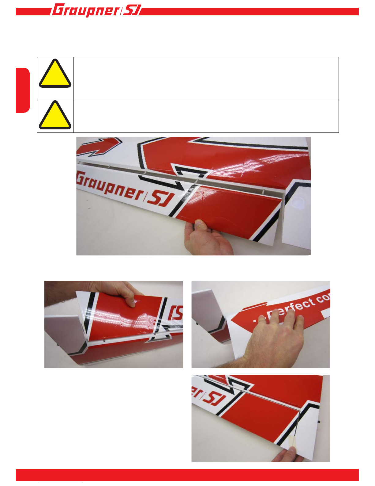
Slitting the decals over a hinge line
Apply the decal as described in the section above: Applying the decals. Now use a sharp knife to cut along
the edge of, say, the n (7), and rub the decal down over the edge.
Attention!
When slitting the decal take care not to damage the hinge or covering lm underneath.
!
Gradually peel off the backing paper, working from the
end already stuck down, and use the at of your hand
to rub the decal down and onto the model.
Work slowly and steadily to avoid trapping air bubbles under the decal.
All the decals can now be applied using this
procedure, until the model is completely decorated.
Page 58

English
58
Model settings
Centre of Gravity:
The model should balance at a point 115 mm aft
of the wing leading edge, measured at the root.
Attaching the wings to the fuselage
Slide the wing joiner tube (42) into the sleeve in the fuselage (2), and set it central (equal projection on both
sides). Now t one wing panel (8 or 9) onto the wing joiner tube (42), connecting the servo plug to the socket
at the same time. Repeat this procedure with the other wing panel (8 or 9). Secure the wings (8, 9) using the
retaining screws (43).
Attention!
It is important that no cables are caught or jammed between the wing panels (22 or 23) and
the fuselage (2), otherwise a wire could break, leaving the model uncontrollable; it could then
crash.
!
Basic control surface travels:
Before setting up the control surface travels, assemble the model completely, as if you were about to y it. Move
the throttle stick on the transmitter to the Stop position, then switch the receiving system on. In the transmitter’s
Servo Settings menu set all control surfaces to the centre (neutral) position. Now use a set-square to measure the
control surface travels: move the transmitter stick to full travel for each control surface individually, and use the
transmitter’s servo adjustment menu to set the travels stated in the table below.
Description
Deec-
tion in
mm
EXPO in %
Aileron travel
+70
30
-70
Rudder travel
+100
60
-100
Elevator travel
+110
60
-110
Page 59

English
59
INNOVATION & TECHNOLOGY
Using Planejama (aeroplane nightshirt)
The Planejama (aeroplane nightshirt) consists of protective bags with carefully sewn seams. The bags are made
of hard-wearing fabric, and protect your model from dents, scratches and other damage in transit. The Planejama
can also be used at the ying eld when the model is fully rigged. In this guise it protects the aircraft from the
effects of sunshine, and briey from rain while you move it under cover.
Slide the protective bags onto the wings and
tailplane of the assembled model.
Slip the protective bag over the n of the assembled
model, and x it to the tailplane bags.
Lay the fuselage bag over the fuselage and attach
it to the tailplane bags. Now wrap the bag under the
fuselage and then round the cowl at the nose.
Page 60

60
All that remains is to wish you many hours of happy ying with your HoTTrigger
Your team!
English
60
Graupner/SJ GmbH
Henriettenstrasse 96
73230 Kirchheim/Teck
Germany
No liability for printing errors. Technical changes reserved! Keine Haftung für Druckfehler.
Technische Änderungen vorbehalten!
• When you have completed the model in accordance with the instructions, pro-grammed the
radio control system as stated, and charged all the batteries, there is nothing to stop you
ying the model for the rst time.
• The maiden ight should be carried out in at calm conditions, or no more than the lightest of
breezes.
• A range check with the motor running is also recommended!
• Building the model is very simple; ying it represents a greater challenge.
Maiden ight
Attention!
This aircraft should only be own by experienced model pilots!
!
Environmental protection notes
After every ying session clean the model and the transmitter using a suitable cleaning agent
only: we recommend a lint-free cloth. Never use chemical cleaners, solvents, methylated spirit
(‘meths’), white spirit (‘turps’) or similar. After every ight check that all screwed joints are still
tight. If an area of covering lm should come loose or become wrinkled, re-attach it using a lm
iron set at no more than 100°C.
Care and maintenance
The presence of this symbol on a product, in the user instructions or the packaging,
means that you must not dispose of that item in the ordinary domestic waste when
the product comes to the end of its useful life. The correct method of disposal is to
take it to your local collection point for recycling electrical and electronic equipment.
Individual markings indicate which materials can be recycled and re-used. You can
make an important contribution to the protection of our shared environment by reusing the product, recycling the basic materials or re-processing redundant equipment in other ways. Dry cells and rechargeable batteries must be removed from the
device and taken separately to a suitable battery disposal centre. If you don’t know
the location of your nearest disposal centre, please enquire at your local council
ofce.
Page 61

English
61
INNOVATION & TECHNOLOGY
61
Notes
Page 62

English
62
Page 63

English
63
INNOVATION & TECHNOLOGY
Page 64

Die Fa.Graupner/SJ GmbH, Henriettenstrasse 96,
73230 Kirchheim/Teck gewährt ab dem Kaufdatum auf
dieses Produkt eine Garantie von 24 Monaten. Die
Garantie gilt nur für die bereits beim Kauf des Produktes
vorhandenen Material- oder Funktionsmängel. Schäden,
die auf Abnützung, Überlastung, falsches Zubehör oder
unsachgemäße Behandlung zurückzuführen sind, sind von
der Garantie ausgeschlossen. Die gesetzlichen Rechte und
Gewährleistu sansprüche des Verbrauchers werden durch
diese Garantie nicht berührt. Bitte überprüfen Sie vor einer
Reklamation oder Rücksendung das Produkt genau auf
Mängel, da wir Ihnen bei Mängelfreiheit die entstandenen
Unkosten in Rechnung stellen müssen.
Graupner/SJ GmbH, Henriettenstrasse 96, 73230
Kirchheim/Teck, Germany guarantees this product for a
period of 24 months from date of purchase. The guarantee
applies only to such material or operational defects witch
are present at the time of purchase of the product. Damage
due to wear, overloading, incompetent handling or the use
of incorrect accessories is not covered by the guaratee.
The user´s legal rights and claims under garantee are
not affected by this guarantee. Please check the product
carefully for defects before you are make a claim or send the
item to us, since we are obliged to make a charge for our
cost if the product is found to be free of faults.
La société Graupner/SJ GmbH, Henriettenstrasse 96,
73230 Kirchheim/Teck, Allemagne, accorde sur ce produit
une garantie de 24 mois à partir de la date d´achat. La
garantie prend effet uniquement sur les vices de fonctionnement et de matériel du produit acheté. Les dommages
dûs à de l´usure, à de la surcharge, à de mauvais
accessoires ou à d´une application inadaptée, sont exclus
de la garantie. Cette garantie ne remet pas en cause les
droits et prétentions légaux du consommateur. Avant toute
réclamation et tout retour du produit, veuillez s.v.p. contrôler
et noter exactement les défauts ou vices.
Garantie-Urkunde
Warranty certi cate / Certi cat de garantie
Übergabedatum
Date of purchase/delivery
Date de remise
Name des Käufers
Owner´s name
Nom de I`acheteur
Straße, Wohnort
Complete adress
Adresse complète
Wir gewähren auf dieses Erzeugnis eine / This product is / Sur ce produit nous accordons une
Garantie von
warrantied for
garantie de
24
Monaten
months
mois
Servicestellen / Service / Service après-vente
Graupner/SJ-Zentralservice
Graupner/SJ GmbH
Henriettenstrasse 96
D-73230 Kirchheim / Teck
Servicehotline
(+49) (0)7021/722-130
Montag - Donnerstag
7:30 -9:00 Uhr
9:15 -16:00 Uhr
Freitag
9:00 - 13:00 Uhr
Die Adressen der Servicestellen außerhalb Deutschlands
entnehmen Sie bitte unserer Webseite www.graupner.de.
For adresses of service points outside of germany please
refer to www.graupner.de/en/.
Pour adresses des points de service situés en dehors de
l‘Allemagne s‘il vous plaît se référer à www.graupner.de/fr/.
Firmenstempel und Unterschrift des Einzelhändlers
Stamp and signature of dealer
Cachet et signature du vendeur
64
 Loading...