

GRATTEN GA1022CAL, GA1042CAL, GA1202CAL, GA1302CAL, GA1062CAL User Manual
...

Announcement
The content of this manual is based on the current production models. As a
progressive company we pursue a policy of continuous product development and
improvement. Thus the content and operational procedure in this manual could be
changed without prior notice.
Copyright
© 2012 NANJING GLARUN-ATTEN TECHNOLOGY CO. LTD All Rights Reserved.
Trademark Logo
is the registered trademark of NANJING GLARUN-ATTEN
TECHNOLOGY CO. LTD.
Declaration
The products of the company are under protection of the
People's Republic of China Patent that has been approved or is
pending.
The company reserves the right to change the specifications
and prices.
Limited by the People's Republic of China and international
copyright laws, any entities and individual cannot copy or
spread the content of this manual (including electronic
manuals) as well as translate the content into other languages
without authorization of NANJING GLARUN-ATTEN
TECHNOLOGY CO. LTD.

Security terms and characters
Terms in this manual. The following terms may appear in this manual:
Warning
The warning announcement points out the operation or condition that
may endanger the operators.
Notice
The notice announcement points out the operation or condition that
may cause damage to the product or other properties.
Terms on the product. The following terms may appear on the product:
Danger It represents that harms may be caused to you at once if you perform
the operation.
Warning It represents that latent harms may be caused to you if you perform
the operation.
Notice It represents the damage possibly caused to the product or other
properties if you perform the operation.
Characters on the product. The following characters may appear on the product:
Notice
Please read
the manual
Protective
ground terminal
Chassis
ground terminal
Measuring
ground terminal


Introduction to GA1000 series of digital
storage oscilloscope
GA1000 series of digital storage oscilloscope is small in size and flexible to operate. It
adopts a TFT LCD and a pop-up menu for display, and can remarkably improve the
working efficiency by its ease of use.
GA1000 oscilloscope has a real-time sampling rate as high as 2GSa/s, therefore it is
capable of catching complex and quickly changing signals. It supports storage of USB
equipment, and is capable of updating and upgrading the system software by a USB
flash disc.
GA1000 series of oscilloscope has excellent performance, various functions and
competitive cost to performance ratio.
Model Bandwidth Sampling Rate
GA1102CAL
100MHz
1GSa/s
GA1202CAL 200MHz 2GSa/s
GA1302CAL 300MHz 2GSa/s
Characteristics:
The oscilloscope has a totally new ultrathin appearance design, and is small in
size and more portable
A 7-inch widescreen color TFT LCD displays clear, crisp and more stable
waveform display
Storage/ Memory depth: single channel: 40Kpts; double channels: 20Kpts
Various trigger functions: Edge, Pulse, Video, Slope and Alternation
Unique digital filtering and waveform recording functions
Pass/Fail function
GA1022CAL 25MHz 1GSa/s
GA1042CAL 40MHz 1GSa/s
GA1062CAL 60MHz 1GSa/s

32 kinds of automatic measurement and manual cursor tracking measurement
functions
Two groups of reference waveforms, 16 groups of common waveforms, 20
groups of internal storage/output; support waveform setting, external storage
and output of CSV and bitmap file by USB flash disc (CSV and bitmaps cannot be
output from USB flash disc)
Adjustable waveform brightness and screen grid brightness
The pop-up menu display mode realizes more flexible and more natural for
users’ operations
Various kinds of language interface display, Chinese and English
On-line help system
Shortcut key PRINT, support print screen
Standard configuration interfaces: USB Host, USB Device, RS-232
USB Host: support storage of USB flash disc and upgrading of USB flash disc
system software
USB Device: support PC connection for remote communication;
GA1000 series of digital storage oscilloscope accessories:
User's manual
Product warranty card
Certificate of approval
1:1/10:1 probes(2 PCS ea)
Power cord satisfying the standard of the user's country
USB cable
CD (containing PC software GAScope1.0)

Content Summary
The manual introduces related information about the operation of this series of digital
oscilloscope and comprises the following chapters and sections:
Chapter “Introduction” introduces the front panel, the user interface, the function
check and the probe compensation of the oscilloscope.
Chapter “Function Introduction and Operation” systematically introduces the
function and operation of the oscilloscope in detail.
Chapter “Application Example” includes many measure examples offered for
reference for users.
Chapter “System Prompt and Fault Recovery” introduces the system prompts
and lists some simple faults and solutions so that the users are capable to
rectify simple faults.
Chapter “Service and Support” introduces the warranty and technical support of
this series of product.
Chapter “Appendix A: Technical Specification” introduces the technical
specification of this series of oscilloscope in detail.
Chapter “Appendix B: Default Setting” lists related factory settings.
Chapter “Appendix C: Daily Maintenance and Cleaning” introduces the way to
maintain the oscilloscope.


Catalogue
Chapter 1 Introduction………………………………………………………………………………………………………………………….…………1
1.1 Accidence of front panel and user interface ………….……………..………………..… 1
1.1.1 Front panel………………………………………………………………………………………………1
1.1.2 Back of instrument……………………………………………………………………….………4
1.2 Function check…………………………………………………………………………………………………5
1.3 Probe…………………………………………………………………………………………………………………6
1.3.1 Probe safety……………………………………………………………………………………………6
1.3.2 Probe attenuator setting…………………………………………..……….…………………6
1.3.3 Probe compensation……………………………………………………..………………………7
Chapter 2 Function Introduction and Operation……………………..………9
2.1 Menu and control button…………………………………………………………………….………………9
2.2 Connector…………………………………………………………………………………….………………………11
2.3 Default setting………………………………………………………………………………….…………………12
2.4 [Universal] knob………………………………………………………….………………………………………13
2.5 Vertical system……………………………………………………………………………………………………14
2.5.1 Channels CH1 and CH2……………………………………………………………….……………14
2.5.2 Application of [POSITION] and [VOLT/DIV] knobs of the vertical system
……………………………………………………………………………………………………………………………….20
2.5.3 Implementation of MATH function…………………………………………………………20
2.5.4 Implementation of REF function………………………………….…….……………………27
2.6 Horizontal system……………………………….……………………………………………………………29
2.6.1 Horizontal control knob…………………………………………………………..………………30

2.6.2 Window expansion………………………………………….…………………………………………31
2.7 Triggering system………………………………………………………………………………………………32
2.7.1 Signal source………………………………………………………………………………………………33
2.7.2 Type……………………………………………………………………………………………………………33
2.7.3 Coupling……………………………………………………………………………………………………42
2.7.4 Trigger hold-off…………………………………………………….……………………………………42
2.8 Signal acquisition system…………………………………………………………………………………44
2.9 Display system……………………………………………………………………………………………………48
2.9.1 X-Y mode………………………………………………………………..………………………………50
2.10 Measurement system…………………………………………………………………………………………52
2.10.1 Scale measurement……………………………………………….………………………………52
2.10.2 Cursor measurement…………………………………………….………………………………52
2.10.3 Measurement…………………………………………….…………………………………………56
2.11 Storage system……………………………………………………………..……………………………………63
2.12 Auxiliary system…………………………………………………………………………………………………69
2.12.1 System status…………………………………………………………………………………………71
2.12.2 Language selection…………………………………………………………………………………71
2.12.3 Self correction…………………………………………………………………………………………72
2.12.4 Self test……………………………………………………………………………………………………72
2.12.5 Firmware upgrading………………………………………………………………………………74
2.12.6 Test passed………………………………………………………………………………………………74
2.12.7 Waveform recording………………………………………………………………………………78
2.12.8 Interface setting……………………………………………………………………………………80
2.13 Help function……………………………………………………………………………………………………81

Chapter 3 Application Examples…………………………………………………………………………………………82
3.1 Simple Measurement……………………………………………………………………………………………82
3.2 Cursor Measurement……………………………………………………………………………………………84
3.2.1 Measurement of width of spike pulse……………………………………………………84
3.2.2 Measurement of amplitude of spike pulse……………………………………………84
3.3 Single signal catching……………………………………………………………………………………86
3.4 Detailed information of analysis signal………………………………………………………87
3.4.1 Noise signal observation…………………………………………………………………………87
3.4.2 Separation of signal from noise…………………………………………………………87
3.5 Application of X-Y function………………………………………………………………………88
3.6 Application of arithmetical operation in communication signal difference
analysis…………………………………………………………………………………………………………………90
3.7 Screen capture………………………………………………………………………………………………………91
Chapter 4 System prompt and Fault Recovery…………………….………..……………92
4.1 System prompt message description………………………………………………………………92
4.2 Fault troubleshooting…………………………………………………………………………………………94
Chapter 5 Service and Support…………………………………………………………….……………………………………………96
5.1 Maintain summary……………………………………………………………………………………..………96
Chapter 6 Appendix…………………………………………………………………………………………………………………………………………97
Appendix A: Technical specification……………………………………………………………………97
Appendix B: Default setting…………………………………………………………………………………102

Appendix C: Daily maintenance and cleaning…………..…………………………………………106

1
This series of digital storage oscilloscope is a
small and light portable instrument that can be
measured by a ground voltage as reference.
This chapter introduces how to implement the
following tasks:
Accidence of front panel and user interface
Implement brief function checks
Match probe attenuation coefficients
Implement probe compensation
DIGITAL STORAGE OSCILLOSCOPE
Introduction

1
1.1 Accidence of front panel and the user
interface
This section will make you understand the front operation panel of this series of digital
oscilloscope at first before use.
The content below simply describes and introduces the front panel and the back part
of this series of digital oscilloscope so that you can know this series of digital
oscilloscope well within the shortest time.
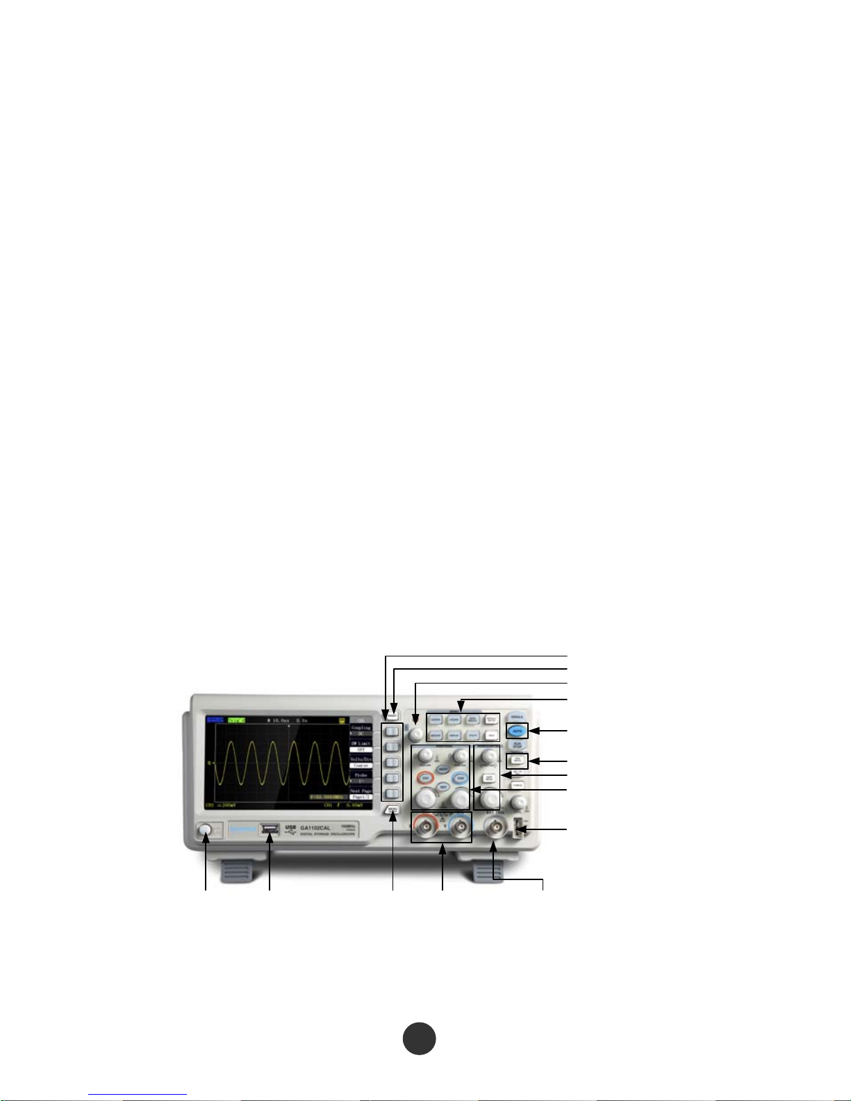
1.1.1 Front panel
This series of digital oscilloscope has a front panel that is simple but clear in function,
and is convenient for a user to finish basic operations. Knobs and functional keys are
arranged on the panel. Five grey keys which have been arranged in a row on the left
side of a display screen are option keys. The current menu can be provided with
different options. The other keys are function keys that can be set in different
functional menus or directly obtain specific function application. The knobs can be
used for quickly regulating the corresponding setups of the oscilloscope.
Attention: in this specifications, 【】represents the keys and knobs of the oscilloscope,
and ‘‘’’ represents the menu options displayed in a program interface.
Power Button USB Port Menu On/Off Input Channel
for Analog Signal
External
Trigger Terminal
Function Keys
Print Screen
Universal Knob
Menu Controls
Auto Setup
Advanced Trigger
ControlsHorizontal Controls
Vertical Controls
Probe Compensation Signal
Output Terminal/ Ground
Terminal
Figure 1-1 Figure of Front Panel controls
①②③
④
⑤
⑦
⑥
⑧⑨ ⑩ ⑪⑫⑬⑭⑮
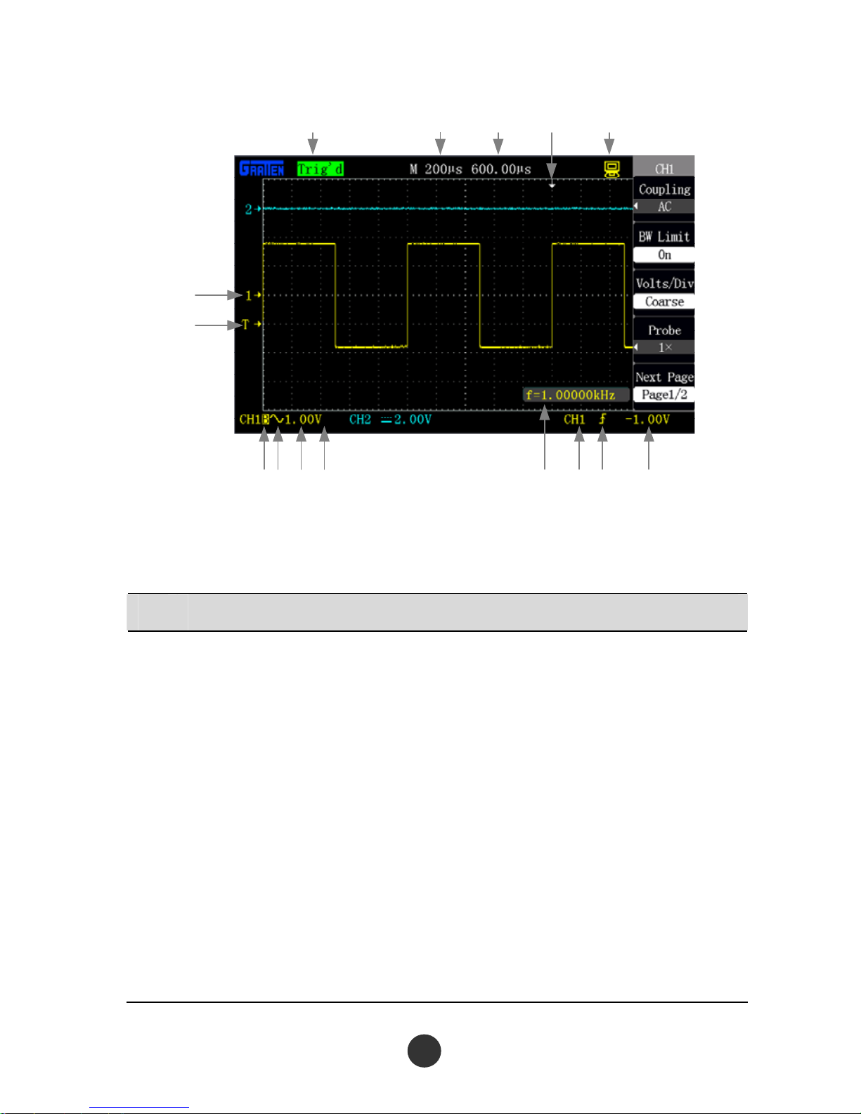
Figure 1-2 Interface display
No. Details
①
Tri
gger status
Armed: The oscilloscope is acquiring pre-triggering data. All triggers are ignored
in this state.
Ready: The oscilloscope has acquired all the pre-triggering data and is ready to
accept a trigger.
Trig’d: The oscilloscope has caught a single trigger and acquires the data after
triggering.
Stop: The oscilloscope has stopped acquiring waveform data.
Auto: The oscilloscope is at an auto mode and acquires the waveform at a
non-triggered state.
Scan: The oscilloscope continuously acquires and displays the waveform at a
scan mode.
2

The r
eading displays the setup of a main time base.
②
It disp
la
ys a time reading from the central scale.
③
④
The identifier displays the horizontal trigger position.
The horizontal [POSITION] knob is used for regulating the horizontal trigger
position
It represents the oscilloscope is connected to a computer
⑤
⑥
The identifier displays a zero electrical level standard point of the channel
waveform.
The identifier is displayed only when the channel is open
The identif
ier displays a trigger electrical level
⑦
The iden
tifier displays bandwidth limit of the channel.
⑧
The iden
tifier displays coupling mode of the channel.
⑨
The re
ading displays vertical scale coefficient of the channel.
⑩
The ide
n
tifier displays inverse phase of waveform of the channel.
⑪
The r
e
ading displays counting frequency of a frequency meter.
⑫
It disp
la
ys a trigger source selected at present.
⑬
The ico
n
displays a selected trigger type.
⑭
The read
ing displays a set trigger electrical level value.
⑮
3
4
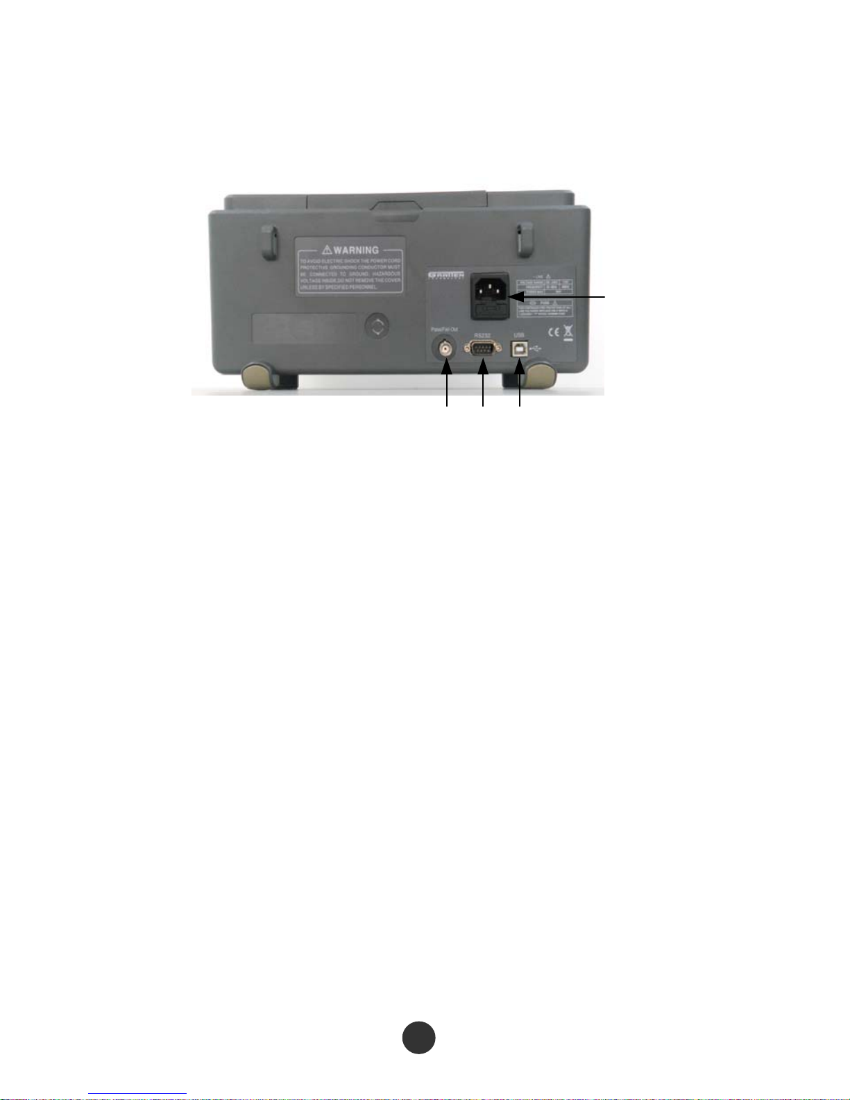
1.1.2 Instrument back
This series of digital oscilloscope provides various standard interfaces, as shown in
the figure below :
4
1 2 3
1. Pass/Fail output port: output a Pass/Fail detection pulse
2. RS-232 interface: connect test software or waveform printing (a bit slow)
3. USB Device interface: connect test software or waveform printing (quick)
4. Power input interface: input a three-pin power supply
1.2 Function check
Carry out a quick function check to check whether the oscilloscope works normally
according to the following steps:
1. Turn on the power source, and set the default attenuation as 1× according to the
probe option [DEFAULT setup].
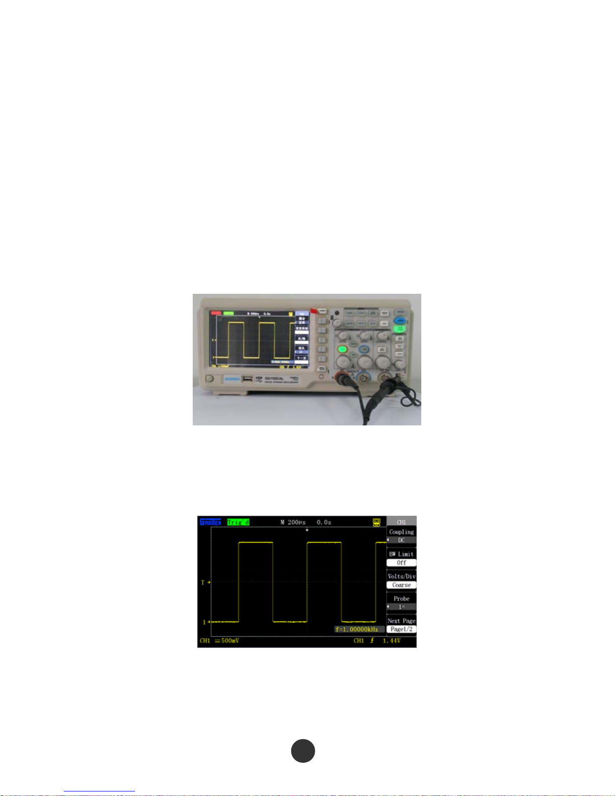
2. Set a switch on a probe of the oscilloscope as ×1 and connect the probe with a
connector CH1BNC of the oscilloscope. Connect a hook-shaped head of the probe
to a probe compensation signal connector marked with ‘‘1KHz’’, and clamp a
grounding hook marked with “GND” by a grounding clamp, as shown in the figure
below:
Figure 1-4 Function detection
3.Press [AUTO]. Within few seconds, CH1 displays a square wave of which the
frequency is 1kHz and the peak-to-peak voltage value is 3V.
Figure 1-5 Probe compensation signal
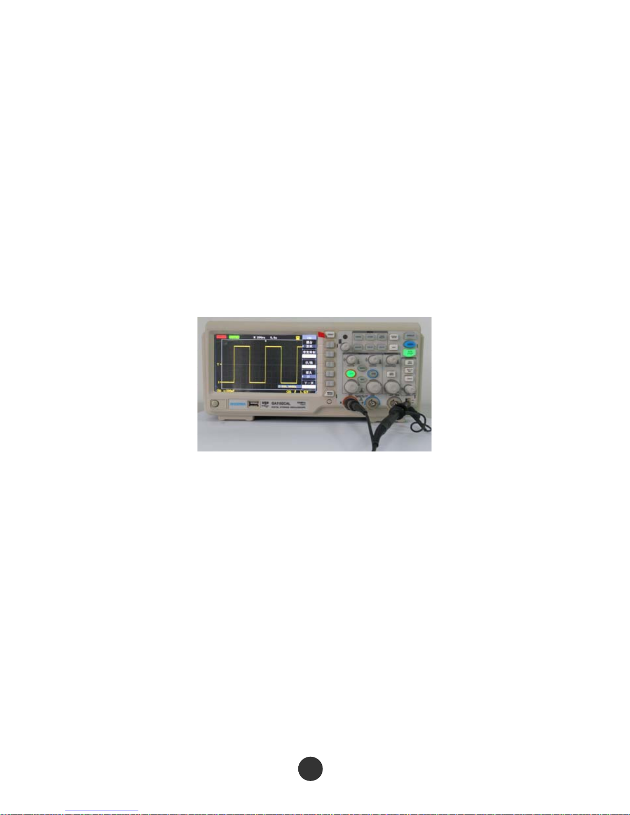
4. Connect the probe with channel 2, and CH2 displays the same waveform after [AUTO]
is pressed.
5

1.3 Probe
1.3.1 Probe safety
Check and obey the rated values of the probe parameters before using it.
A protective cover surrounding the probe main body can prevent fingers from electric
shock.
Probe protective
device
Fi
gure 1-6 Probe
Connect the probe to the oscilloscope and ground the ground terminal before any
measurement.
Attention:
Keep fingers behind the protective curve on the probe main body to prevent electric shock
when using the probe.
Do not contact the metal part on the top of the probe when the probe is connected to a voltage
source.
The signal measured by the oscilloscope uses ‘‘ground ’’ as reference voltage, and the ground
terminal should be grounded correctly to prevent short circuit.
1.3.2 Probe attenuation setting
The probe has different attenuation coefficients that influence the vertical scale of the
signal. The “ATTENUATION” switch on the probe is ensured to be matched with the
“PROBE” coefficients in the oscilloscope.
Manually set the probe options, press down the vertical menu key, and then select the
“PROBE” option (such as [CH1] →“PROBE”).
6
7
● Default setup of the probe optical is 1X.
● When the “ATTENUATION” switch is set as ×1, the probe limits the bandwidth of the
oscilloscope within 0-10 MHz (different probes have different specifications).
Ensure that the switch is set to be ×10 when to use the full bandwidth of the
oscilloscope.
1.3.3 Probe compensation
Carry out probe compensation when the probe connect the channel for the first time so
as to match the probe with the channel. Under compensation or Over compensation of
the probe may cause measurement errors or mistakes.
Figure 1-7 Probe compensation connection figure
1. Set the probe coefficient to 10X in channel menu, set the switch on the probe to ×10,
and connect the probe of the oscilloscope with channel 1.
2. Connect the end part of the probe to the probe compensation connector “1KHz”,
clamping the connector “GND” by the ground clamp, turn on the channel displayer,
and then press [AUTO] to display the waveform.

3. Check the shape of the di
splayed waveform.
under compensated suitable compensated over compensated
4. If necessary, rotate the adjustable capacitor on the probe handle to realize suitable
compensated.
8

2
This chapter introduces the functional keys and
operations of the front panel of the series of
oscilloscope in detail.
For effectively using the oscilloscope, the
following functions of the oscilloscope are needed
to be known:
Menu and control keys
Connector
Automatic setup
Default setup
“Universal” knob
Vertical system
Horizontal system
Triggering system
Signal acquisition system
Display system
Measurement system
Save system
Auxiliary system
On-line help system
DIGITAL STORAGE OSCILLOSCOPE
Function Introduction
and Operation

9
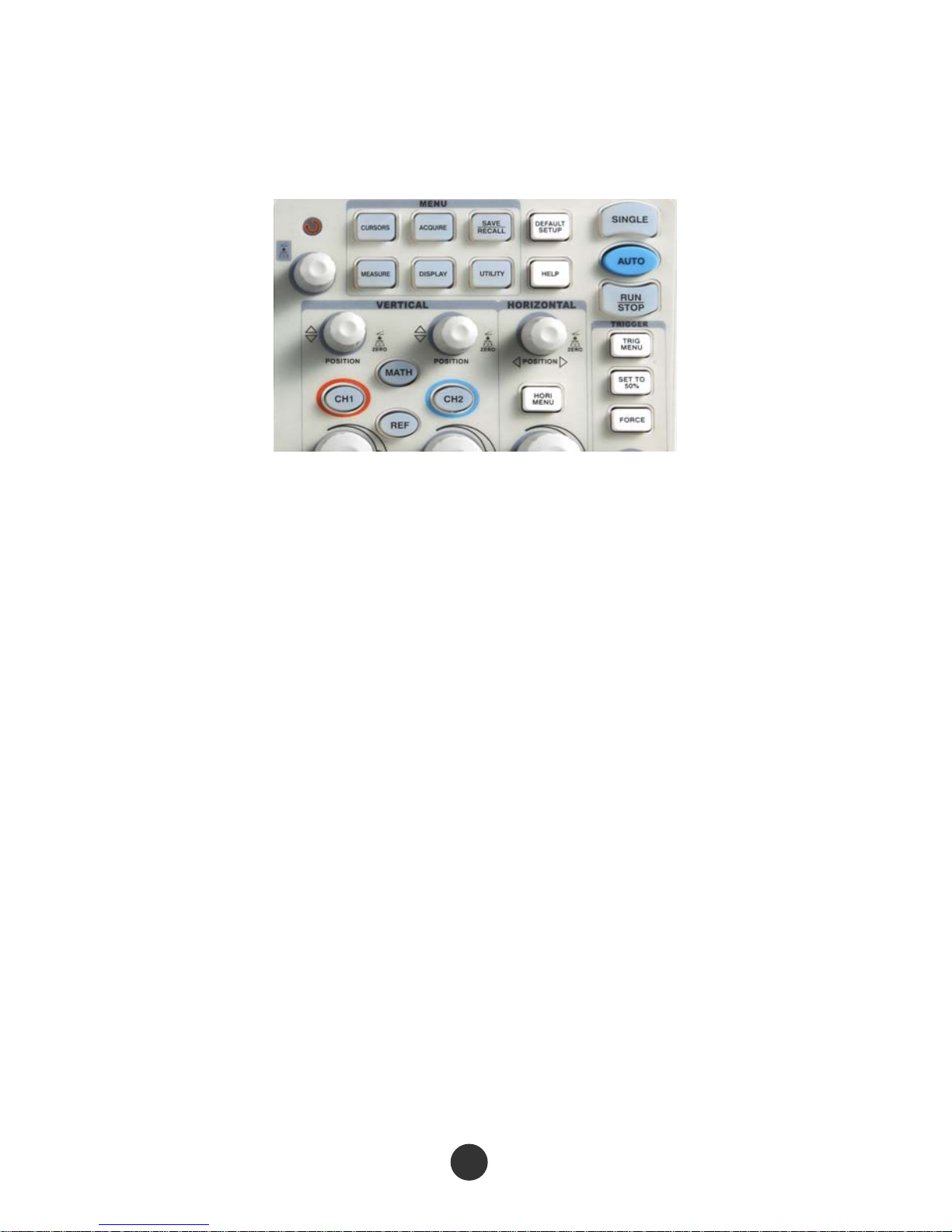
2.1 Menu and control keys
As shown in the figure below :
Figure 2-1 Control keys
All the keys are described as follows:
[CH1], [CH2]: display setup menus of channel 1 and channel 2.
[MATH]: display “ARITHMETICAL OPERATION” function menu.
[REF]: display “REFERENCE WAVEFORM” menu.
[HORI MENU]: display “HORIZONTAL” menu.
[TRIG MENU]: display “TRIGGER” control menu.
[SET TO 50%]: set the trigger electric level as midpoint of the signal amplitude.
[FORCE]: It is used for finishing acquisition of the current waveform no matter
whether the oscilloscope detects trigger, and it is mainly applied to “NORMAL”
and “SINGLE” in the trigger mode.
[SAVE/RECALL]: display the “SAVE/RECALL” menu of setups and waveform.
[ACQUIRE]: display the “ACQUIRE” menu.
[MEASURE]: display the “MEASURE” menu.
[CURSORS]: display the “CURSOR” menu. The [UNIVERSAL] knob can be used for
regulating the position of the cursor when the “CURSOR” menu is displayed and
the cursor is triggered.

10
[DISPLAY]: show the “DISPLAY” menu.
[UTILITY]: display “AUXILIARY FUNCTION” menu.
[DEFAULT SETUP]: recall the default factory setup.
[HELP]: enter the on-line help system.
[AUTO]: automatically set the control state of the oscilloscope so as to display
suitable waveform.
[RUN/STOP]: continuously acquire waveform or stop acquisition
[SINGLE]: Acquire a single trigger, finish acquisition and then stop.

11
2.2 Connector
Figure 2-2 Connector
CH1, CH2: for an input connector of a measured signal.
EXT TRIG: be used as an input connector of an external trigger source. Use [TRIG
MENU] to select “EXT” or “EXT/5” trigger source, and the trigger signal source
can be used for triggering in the third channel while acquiring data in two
channels.
Probe compensation: The probe compensation signal is output and grounded so
that the probe is matched with the channels of the oscilloscope.
This product is grounded by a protective ground wire of a power cord. For avoiding electric
shock, please ensure that the product is reliably grounded before connecting the input end
or output end of the product.
The ground wire of the probe is connected to the ground only. Please do not connect the
ground wire to high voltage.
12
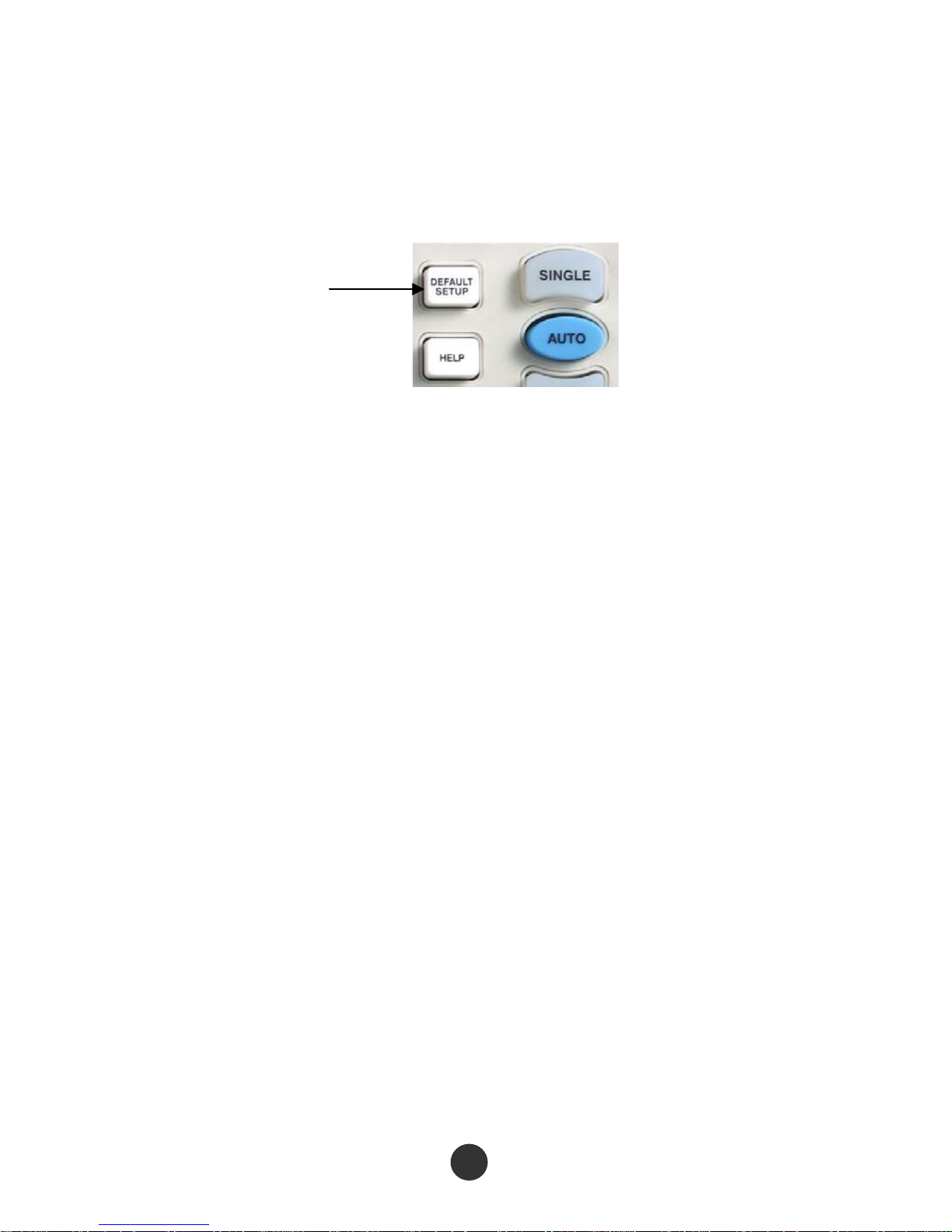
2.3 Default setups
The default setups represent some option parameters that are set before the
oscilloscope leaves factory for normal operations.
Figure 2-3 Default setup key
The [DEFAULT SETUP] key represents the default setup function, most of the options
and control setups of the factory are recalled by pressing them, some setups are not
changed, and the following setups are not reset:
Language options
Saved standard waveforms
Saved setup files
Contrast ratio of display screen
Calibration data
Default setup
13
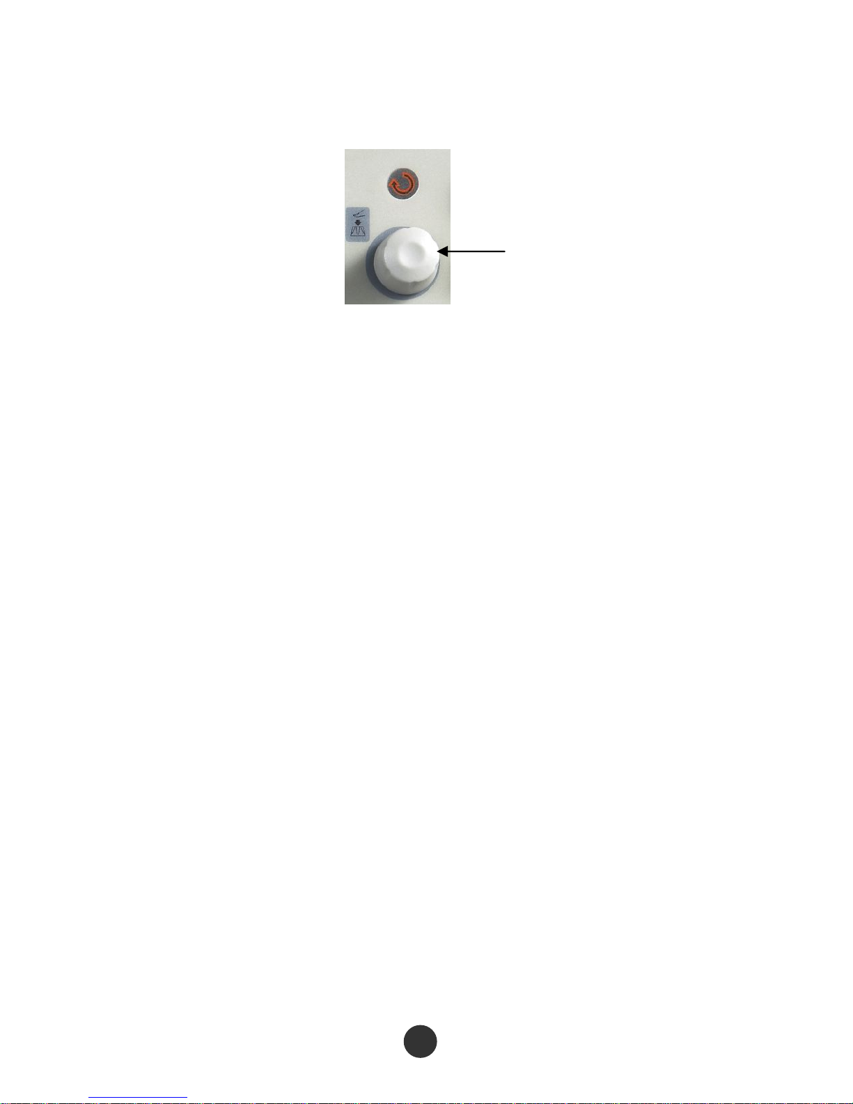
2.4 UNIVERSAL knob
Figure 2-4 Universal knob
This series of digital storage oscilloscope has a special knob-[UNIVERSAL] knob by
which the hold-off time, cursor measurement, pulse width setup, specified row in video
trigger, upper limit and lower limit of filter frequency, horizontal tolerance range and
vertical tolerance range for regulating PASS/FAIL function, waveform frame number
recording and playback in waveform recording function and the like can be changed.
The options for most of the menus can be selected by rotating the [UNIVERSAL] knob.
Universal knob
 Loading...