

Grate Fires GE201G30B30N, THE ROGERS, GE201G30B30P Installation, Operation And Service Manual
Page 1
INSTALLATION OPERATION
AND SERVICE MANUAL
THE ROGERS
VENTED DECORATIVE GAS APPLIANCE/
DECORATIVE COAL SET
PLEASE READ THIS MANUAL CAREFULLY BEFORE INSTALLING AND OPERATING
THE APPLIANCE.
INSTALLER: Leave this manual with the appliance.
CONSUMER: Retain this manual for future reference.
WARNING: If the information in this manual is not followed exactly, a fire or
explosion may result causing property damage, personal injury or loss of life.
- Do not store or use gasoline or other flammable vapors and liquids in the vicinity of this or
any other appliance
WHAT TO DO IF YOU SMELL GAS:
*Do not try to light any appliance.
*Do not touch any electrical switch; do not use any phone in your building.
*Immediately call your gas supplier from a neighbors phone. Follow the gas suppliers
instructions.
*If you cannot reach your gas supplier; call the fire department.
- Installation and service must be performed by a qualified installer, service agency or the gas
supplier.
Warning: This appliance is equipped for either Natural or Propane Gas. Field conversion is not permitted.
This appliance can be returned for conversion.
Page 2
Pg. 1
The Evans consists of a cast iron grate and a gas coal burner complete with
vermiculite and coals.
MODELS SIZE MINIMUM FIREPLACE SIZE
GE201G30B30N
GE201G30B30P
18.5" W.F., 13" W.B., 9.5" D., 13"H. 19" W., 13.5" W.B., 10" D.,
13.5" H.
Minimum flue size 6".
Maximum BTU for Natural Gas - 30,000 intake
Maximum BTU for Propane - 25,000 intake
INTRODUCTION
Grate Fires was the first company in America to provide authentic, heat generating fires with
simulated coals. We have been in business since 1995.
Please read this manual carefully before operation of the appliance. Then relax, sit back and enjoy
your new fire.
1. GENERAL INSTRUCTIONS FOR INSTALLING THE EMBERS VENTED
DECORATIVE GAS COAL BURNER
(a) Grate Fires products should be installed by a competent gas appliance installer and must be
installed only in a solid fuel burning fireplace with a working flue and constructed of noncombustible material. There must be an adequately sized flue. The draw of which must be
adequate to safely vent all emissions to the outside without spillage.
(b) The installer should assure that the chimney is sound, free from obstructions and able to vent
all flue products safely to the outside. The area of the hearth surrounding the fire should be
of non-flammable material, such as fire resistant brick or refractory.
The area immediately in front of the appliance should be made of nonflammable material as
well. Carpets of flammable material should be at least (4) inches from either side of the
appliance and one foot from the front.
(c) Never throw cigarettes or any other flammable material in the fire as the buildup of ashes
may choke the burner.
(d) When supplied as a vented decorative coal set, the product may be installed in a non-
combustible hearth having an adequate masonry tile or lined chimney.
THE ROGERS
Page 3

Pg. 2
(e) A smoke test (see #8) must be conducted prior to leaving the connected appliance to assure
that all flue products are exhausted properly and that there is no spillage of fumes back into
the room. All restrictors blocking the chimney shall be removed. Certain types of chimney
caps and hoods have an adverse effect on the “draw” of the chimney, particularly with open
decorative effect gas fires , and they should be removed if it is confirmed that they are
adversely affecting the “draw” of the chimney. The chimney should serve only one
fireplace; gas/coal fires should never be connected to an existing flue that is serving another
appliance.
NOTE: THE INSTALLATION MUST CONFORM WITH LOCAL CODES OR IN THE
ABSENCE OF LOCAL CODES, WITH THE CURRENT NATIONAL FUEL GAS CODE,
ANSI Z 223.1/NFPA 54 OR THE NATURAL GAS AND PROPANE INSTALLATION
CODE, CSA B149.1. A 1/8 INCH N.P.T. PLUGGED TAPPING, ACCESSIBLE FOR TEST
GAGE CONNECTION MUST BE PROVIDED, IMMEDIATELY UPSTREAM OF THE
GAS SUPPLY CONNECTION TO THE APPLIANCE.
Adequate combustion and ventilation air must be provided.
The appliance and its individual shutoff valve must be disconnected from the gas supply piping
system during any pressure testing of that system at pressures in excess of ½ psi. (3.5kPa).
The appliance must be isolated from the gas supply system by closing its individual manual shutoff
valve during any pressure testing of the gas supply system at test pressures equal to or less than ½
psi. (3.5kPa).
2) AIR FOR COMBUSTION AND VENTILATION
In open rooms of normal construction (without storm windows or tightly fitting doors) sufficient
combustion air can usually be supplied by infiltration. Ensure that the installation location is
adequately ventilated and that air flow is not obstructed around the appliance.
3) APPLIANCE LOCATION CLEARANCE
(a) Due to high temperatures the appliance should be located out of traffic areas and at least 36"
away from furniture and draperies.
(b) Children and adults should be alerted to the hazards of high surface temperatures and open
flames.
( c) Young children should be carefully supervised when they are in the same room as the
appliance.
(d) Clothing or any flammable material should not be placed on or near the appliance.
(e) Any safety screen or guard removed for servicing an appliance must be replaced prior to
operating the appliance.
Page 4
Pg. 3
(f) MINIMUM CLEARANCES TO NON COMBUSTIBLES: Sides 0", Back 0", Floor 0".
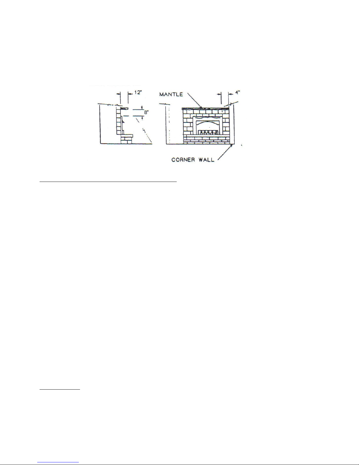
(g) MINIMUM CLEARANCES TO COMBUSTIBLES: Side 4", Back 0", Floor 0", to
combustible mantle 8". Mantle may extend up to 12" from the wall.
(h) When there is no existing fireplace or in new construction, the appliance may be installed
using a 6" “B” vent with our 20" Zero Clearance Firebox.
4) NATURAL GAS AND PROPANE PIPING
(a) The installation must conform with local codes or, in the absence of local codes, with the
current National Fuel Gas Code ANSI Z223.1/ NFPA 54 in the US or the natural gas and
propane Installation Codes, B149.1 in Canada.
(b) Before any system of gas piping is finally put to service, it should be carefully tested to
ensure it is gas tight. As an aid in determining where the gas may leak, it is recommended
that a soap suds solution be used. Under no conditions shall a live flame or fire be used to
locate a gas leak.
( c) The minimum inlet gas pressure permissible is 5" W.C. for natural gas and 10" W.C. for
propane gas for the purpose of input adjustment.
(d) The maximum inlet gas supply pressure permissible is 13.8 W.C. (3.45 kPa) propane and
7.7 W.C. (3.45 kPa) natural gas.
(e) A ½" natural gas supply pipe is required to ensure adequate capacity. It is recommended
that a union be placed in the supply piping to facilitate the easy removal and servicing of the
burner assembly.
(f) This appliance has been set for 30,000 btu/h for natural gas and 25,000 btu/h for propane at
sea level rating. Adjustment to orifice size must be made for altitudes above 2000 feet.
Consult with the manufacturer for recommendations.
5) VENTING
When installing this appliance into a fireplace it is recommended that the chimney be thoroughly
cleaned before installation and checked for soundness and general condition.
(a) The flue diameter must be no less than 6 inches. The height of the chimney must be a
minimum of 12 feet. The fireplace should be serviced annually and the chimney checked
Page 5
Pg. 4
for soot buildup and/or chimney falls of material that could over a period, choke the burner.
If the chimney shows signs of deterioration it is recommended that a suitable liner be
installed.
(b) Where there is no existing chimney or in new construction the appliance may be installed
using 6" diameter “B” vent and the horizontal vent length is not to exceed 6 feet.
( c) When this unit is installed in an existing fireplace the damper must be welded or bolted in a
minimum open position of 21.7 square inches for a 12 foot chimney or remove it
completely. The minimum size flue opening is 6 inches.
CAUTION: Do not connect this appliance to a chimney flue serving a separate solid-fuel burning
appliance.
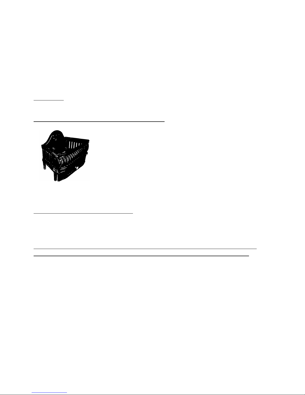
6) ROGERS GRATE ASSEMBLY INSTRUCTIONS
Parts: Back, 2 Sides, Front, Coverplate, 8 Bolts, 8 Nuts
1) Lay rear piece on flat surface, face up.
2) Attach end pieces with legs to back. End pieces have metal extending
1/4" beyond on leg. This leg goes to the rear. Do not tighten bolts.
3) Attach front piece to ends. Thin side of front piece goes on top.
4) Gradually tighten bolts until front, rear and ends are aligned. Do not
over tighten.
7) INSTALLATION INSTRUCTIONS
IMPORTANT: The main supply shut-off valve/tap must never be located inside the firebox and
must be within arm’s length from the fire and accessible at all times.
Grate Fires cannot and will not accept any warranty claim if the appliance has not been
installed to comply with the following instructions and with local and national codes.
(a) Check all screws and nuts on the burner for tightness of connection. With the controls facing
the front, center the burner tray in the base of the fireplace.
(b) Before you connect the burner, carefully place the grate over the burner tray making sure
there is a 3/4" gap between the grate and the back of the burner tray. When properly
positioned no part of the burner tray may project beyond the vertical opening of the
fireplace.
( c) Temporarily remove the grate and connect the burner using a 3/8" flex hose to the gas line
located inside the fireplace. The supply pressure at the fire should be no less than 5 W.C. for
natural gas and 10 W.C. for propane. When possible bring the gas line up through the back
right side corner.
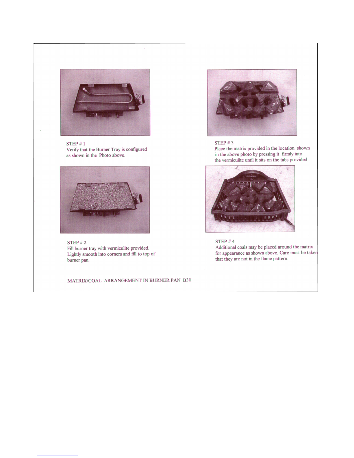
(d) Fill the burner tray with vermiculite and place the coals. (see picture)
(e) Replace the grate before lighting.
Page 6
Pg. 5
GE201 B30
Page 7
Pg. 6
Page 8
Pg. 7
FOR YOUR SAFETY READ BEFORE LIGHTING
WARNING: If you do not follow these instructions exactly, a fire or explosion may result
causing property damage, personal injury or loss of life.
A. This appliance has a pilot which must be lighted by hand. When lighting the pilot, follow these
instructions exactly.
B. BEFORE LIGHTING smell all around the appliance area for gas. Be sure to smell next to the floor
because some gas is heavier than air and will settle on the floor.
WHAT TO DO IF YOU SMELL GAS
* Do not try to light any appliance.
* Do not touch any electric switch; do not use any phone in your building.
* Immediately call your gas supplier from a neighbor’s phone. Follow the gas
supplier’s instructions.
* If you cannot reach your gas supplier. Call the fire department.
C. Use only you hand to push in or turn the gas control knob. Never use tools. If the knob will not push
in or turn by hand, don’t try to repair it. Call a qualified service technician. Force or attempted
repair may result in a fire or explosion.
D. Do not use this appliance if any part has been under water. Immediately call a qualified service
technician to inspect the appliance and to replace any part of the control system and any gas control
which has been under water.
LIGHTING INSTRUCTIONS
1. STOP! Read the safety information above on this sheet.
2. If using a grate, remove control access panel below grate.
3. Push in gas control knob slightly and turn clockwise º to “OFF”
NOTE: Knob cannot be turned from “Pilot to “OFF” unless the knob is
pushed in slightly. Do not force.
4. Wait five minutes to clear out any gas. Then smell for gas, including near the floor. If you smell gas,
STOP! Follow “B” in the safety information above on this page. If you don’t smell gas, go to the
next step.
5. Push in gas control knob slightly and turn counter clockwise » to “Pilot.
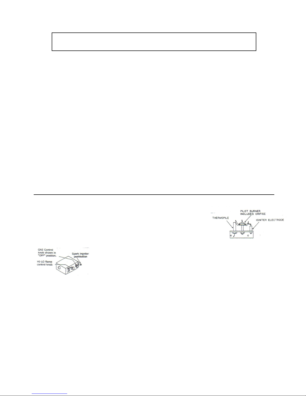
6. Depress the control knob fully and push spark igniter button several times to light the pilot.
7. Continue to hold the control knob in for about 60 seconds after the pilot is lit.
NOTE: If the pilot extinguishes, repeat steps 1, 2, 3 and 4.
8. Turn the control knob counter clockwise » to “ON”.
9. Adjust the HI-LO flame control knob to desired setting.
Page 9

Pg. 8
NOTE: *If the unit is hot, wait 5 minutes to relight the pilot.
*If control knob does not pop up when released STOP, and immediately call
your service technician or gas supplier.
10. Replace control access panel below grate.
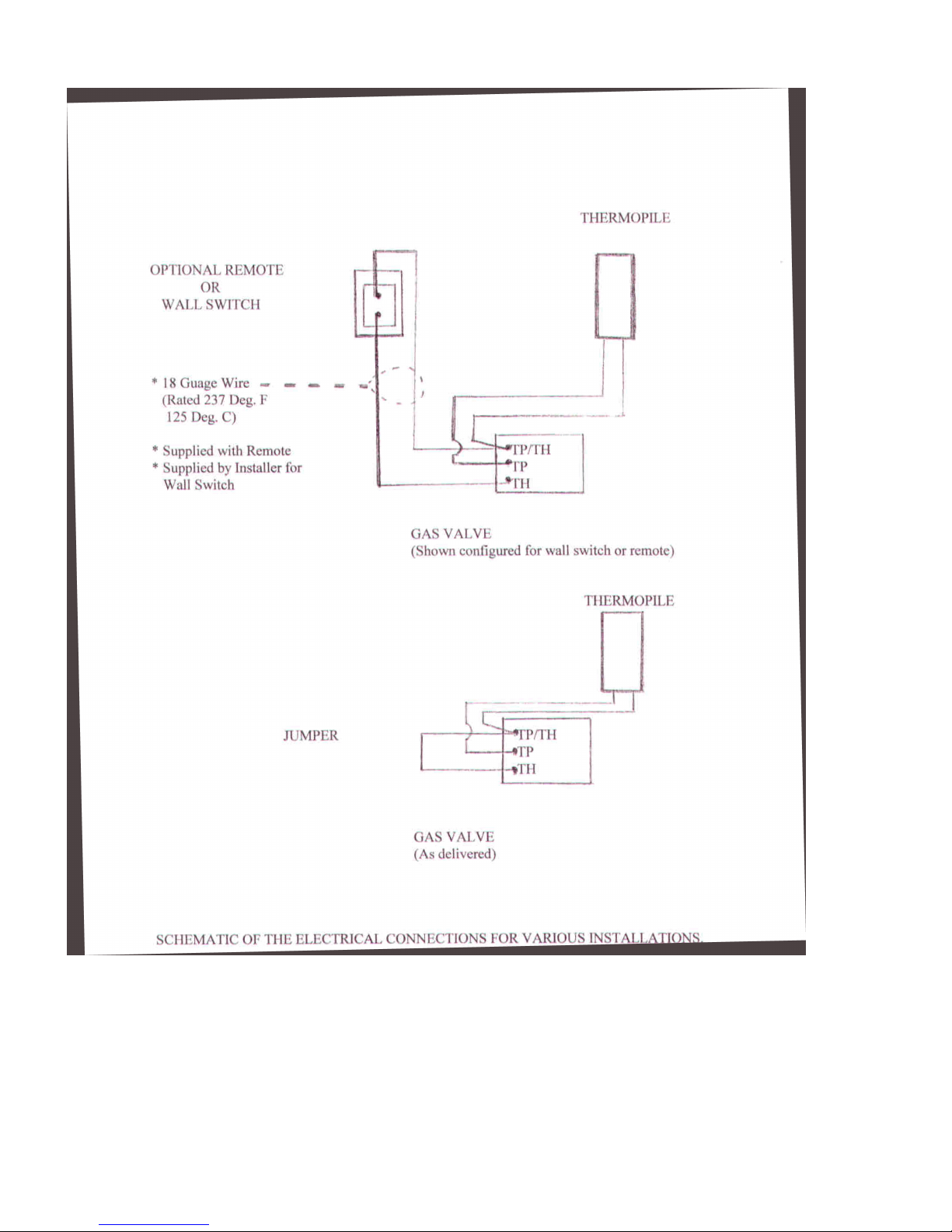
11. Wall switch or remote may now be used to turn main flame ON and OFF.
TO TURN OFF GAS TO APPLIANCE
1. Remove control access panel below grate.
2. Push in gas control knob slightly and turn clockwise to “OFF” position. Do not force.
3. Replace control access panel below grate.
8) OPERATION
(a) Testing, adjusting and checking burner and controls. Follow the instructions and
illustrations given in the drawing to prepare the burner for firing.
To light the burner follow the instructions given on the plate attached to the appliance and
shown below.
Test and adjust all controls under actual operating conditions and in accordance with
applicable local and national installation codes for gas burner appliances.
When lighting the burner wait five (5) minutes to clear and any gas. If you then smell gas,
stop. Follow “B” in the safety information above. If you don’t smell gas, go to the next step
in the lighting instructions.
NOTE: If the piezo igniter fails, the pilot can be lit manually as follows:
1) Position the control knob to “PILOT” position.
2) While depressing the control knob, light the pilot with a match.
3) Hold the control knob down for 60 seconds.
4) Contact your service technician or gas supplier to replace the defective igniter.
(b) DO NOT BURN YOUR FIRE IN THE MAXIMUM POSITION FOR THE FIRST FIVE
HOURS. This will allow for the decorative coals to burn in slowly and be tempered. During
this burning-in period, you may experience a slight smell due to the burning off of organic
materials used in the manufacturing process; this is quite normal. When first lit, the fire will
burn with a bluish flame while the coals are cold. Gradually as the fire settles down it will
have a more realistic yellow flame. This may or may not produce a little soot on the coals as
in the case of a real fire. Should sooting occur, remove the coals and
Page 10

Pg. 9
dust lightly. If sooting continues, please contact Grate Fires for possible solutions.
9) SMOKE TEST
This must be carried out after the appliance has been fully installed to make sure that no products of
combustion spill into the room. The following test must be carried out on every installation.
(a) Close all windows and doors leading to the room in which the appliance is installed.
(b) If a connecting room is fitted with an extractor fan, the test must be conducted with the fan
running and any connecting door left open.
( c) Light the burner and turn to the highest setting, refer to the lighting instructions provided.
(d) After 10 minutes of operation, apply a smoke pencil along the front of the fireplace, 2 inches
below the arched opening and check that the smoke is all being drawn into the firebox. If a
smoke pencil is not available a smoking cigarette or incense wand will suffice.
(e) If the smoke is only partially being drawn into the flue, allow the appliance to run for an
additional 10 minutes and repeat the test.
(f) If the fumes are still not being exhausted completely by the flue, try opening a window
slightly. If this clears up the problem then indications are that the room is tightly sealed and
a permanent air opening must be supplied in the room where the appliance is installed.
Otherwise, check the chimney for obstructions.
(g) Disconnect the gas supply and obtain expert advice.
10) CLEANING PROCEDURE
(a) Turn the control knob to the “OFF” position. This will extinguish the pilot flame.
(b) Wait for appliance to cool. DO NOT ATTEMPT TO CLEAN FIREPLACE WHEN HOT.
( c) Remove control access panel below grate. Any unwanted debris that may have fallen should
be removed by hand.
(d) Do not use a vacuum cleaner to clean any soot or debris from the coal set. The coals are
made of a delicate material which becomes brittle after being heated, and must be treated
gently. A light brushing with a soft brush is all that is required to remove any unwanted
deposits. If it becomes necessary to replace chipped or damaged coals, additional coals are
available together with vermiculite from Grate Fires.
(e) Relight the fireplace referring to the lighting instruction plate attached to the unit or this
manual.
(f) Replace control access panel below grate.
Page 11
Pg. 10
11) GENERAL MAINTENANCE
(a) INSTALLATION AND REPAIRS SHOULD BE DONE BY A GRATE FIRES
QUALIFIED SERVICE PERSON. IT IS RECOMMENDED THAT THE
APPLIANCE BE INSPECTED BEFORE FIRST USE AND AT LEAST
ANNUALLY BY A LICENSED PROFESSIONAL SERVICE PERSON. MORE
FREQUENT CLEANING MAY BE REQUIRED DUE TO EXCESSIVE LINT
FROM CARPETING, BEDDING MATERIAL, ETC. IT IS OF THE UTMOST
IMPORTANCE THAT THE CONTROL COMPARTMENT AND CIRCULATION
AIR PASSAGEWAYS OF THE APPLIANCE BE KEPT CLEAN.
(b) Keep burner and control compartment clean. CAUTION: When cleaning the burner area
always make sure that the gas supply to the appliance is shut off. It the burner fails to light
immediately or appears to be operating abnormally, do not tamper with it, call your licensed
serviceman and have the problem remedied before placing the appliance into operation.
( c) Check periodically that the vent system is unrestricted and that a proper draft is present
when the unit is in operation. All vented appliances require a source of fresh air in order to
vent properly. Recent trends in home improvement and new tighter construction techniques
have contributed to problems with chimneys venting properly. If you suspect
your fireplace is not venting properly, do not operate the unit and seek expert advice.
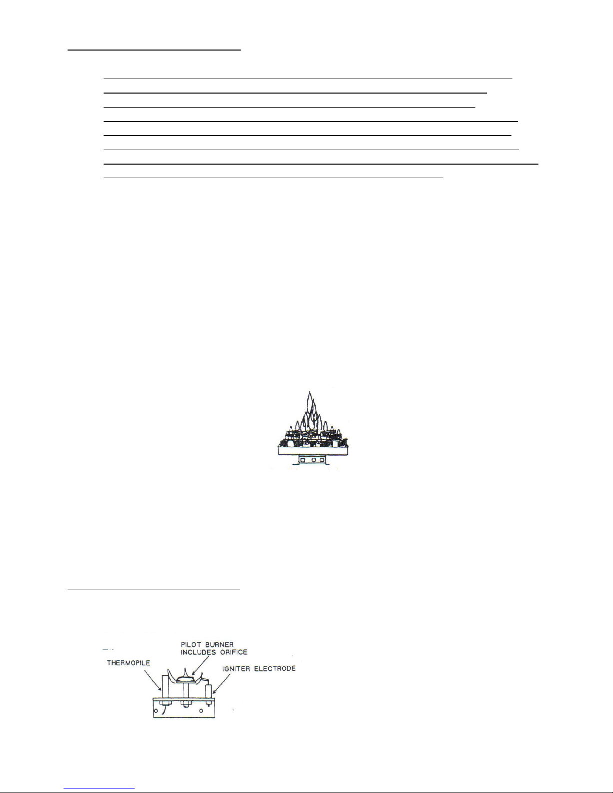
(d) Periodically check the main burner flames. Flames should be evenly spread over the burner
tray and there should be no evidence of significant soot deposit on the coals.
(e) Keep the appliance area clear of combustible materials, gasoline and other flammable vapors
and liquids.
(d) WARNING: Do not burn rubbish of any kind in this appliance. Do not use this appliance if
any part has been under water. Immediately call Grate Fires or your installer to replace any
part of the control system and any gas control which has been under water.
12) PILOT BURNER DIAGRAM
Page 12

Pg. 11
13) TROUBLE SHOOTING
If the appliance fails to light or appears to be operating abnormally, do not tamper with it. Contact a
licensed serviceman or Grate Fires.
To identify the problem with the appliance, you can check the following:
PROBLEM PROBABLE CAUSE REMEDY
Unit will not operate at all *Gas may be shut off *Check that main gas valve
and appliance valve are on
Pilot will not remain lit *Loose connection of
thermopile
*Defective thermopile
*Pilot shield out of place (if
supplied)
*Make sure that connections
are tight
*Replace if defective
*Position shield in front of
thermopile.
No spark at pilot burner *piezo igniter has failed,
loose or damaged cable or
cracked porcelain
*Replace or repair as
necessary
Smell raw gas *leak in supply line or unit.
Check with soap
*Tighten connection
NOTE: THIS GUIDE IS ONLY A MEANS OF IDENTIFYING THE PROBLEM AND ITS
PROBABLE CAUSE. REPAIRS SHOULD BE DONE BY A QUALIFIED SERVICE PERSON.
CALL GRATE FIRES.
-----FOR YOUR SAFETY-----
IF YOU SMELL GAS:
* Open windows
* Don’t touch any electrical switches; do not use any phone in your building
* Extinguish any open flame
* Immediately call your gas supplier from a neighbor’s phone. Follow the gas supplier’s
instructions
* If you cannot reach your gas supplier , call the fire department
14) GUARANTEE
Grate Fires coals (Burner and fuel components only) are guaranteed against breakage in normal use
at their replacement cost for a period of twelve months from the date of purchase. All other
components are guaranteed against defect in materials and workmanship for one year from the date
of purchase. Any other claim under this guarantee must be accompanied by a copy of the original
retail purchase invoice, clearly showing the date of purchase and returned to the supplier. This
guarantee will be invalidated if the appliance is not fitted by a certified technician in strict
accordance with these instructions. If you have a problem, contact Grate Fires, Washington,
Georgia, USA.
Page 13
Pg. 12
PLEASE NOTE
In the interest of product development and the introduction of any new relevant mandatory gas
requirements, Grate Fires, reserves the right to modify and amend the appliance(s) and instructions
as and when deemed necessary, without prior notice. Diligence has been taken to compile these
instructions in order to cover all building/gas utilization code requirements . It is our intention to
cover every occurrence of the Company’s involvement with decorative effect fires. The Company
will not accept any liability for any omissions in these instructions. It is the
gas installation contractor that must check for current compliance with the legal requirements of
installation. These instructions are issued by Grate Fires, who have made every effort to make sure
that they relate to the North American market place, particularly where safety is concerned.
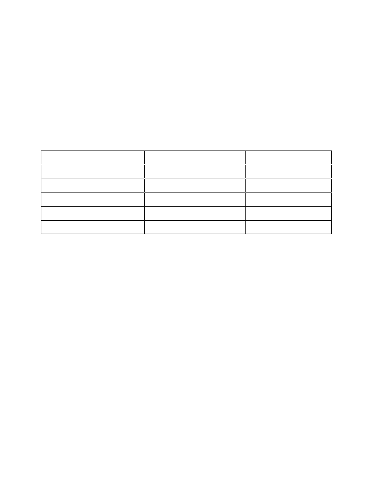
REPLACEMENT PARTS LIST
Type of Control Manufacturer of Control Part Number
Natural Gas and Propane Valve SIT Controls 820.640, 820.639
Pilot Assembly SIT Controls 199.702, .199.701
Piezo Igniter SIT Controls 073.953
Spill Switch ThermoDisc 36T01B3
Thermo Generator SIT Controls 240.002
MADE IN THE USA
 Loading...