

Page 1

STUDIO NEWS
Digital System User Manual
Page 2

Headquarters:
8493 Baymeadows Way
Jacksonville, Florida 32256
800-532-8034
904-737-1367 phone
904-731-0958 fax
support@parkervision.com e-mail
http://www.parkervision.com website
PVTV STUDIO NEWS User Manual G4.02
© 2000 ParkerVision, Inc.
Page 3

Table of Contents
Contacting ParkerVision.......................................... 1
Key Features .......................................................... 2
About this Manual ................................................. 3
Starting PVTV STUDIO NEWS ................................. 4
Digital Control GUI - Right Monitor ........................ 5
Video Switcher Overview .......................................6
Camera Preset Hotkeys .......................................... 7
Using the Vinten Camera with PVTV STUDIO NEWS9
Audio Mixer Overview ...........................................10
Audio Equalizer and Auxiliary Output Overview ..... 11
Assigning Audio Groups ........................................ 12
Assigning Audio Presets..........................................13
Setting Audio Cross-fades ...................................... 14
Broadcast Tools Audio Matrix ................................ 15
Broadcast Tools Audio Matrix ................................ 16
VTR Control Interface Overview .............................17
Using VTRs in PVTV STUDIO NEWS ........................ 18
Setting Up VTR Play Segments ............................... 19
VR Control Interface Overview ...............................20
Setting Up VR File Segments ................................. 21
Using VRs in PVTV STUDIO NEWS .......................... 22
Audio Server Interface Overview.............................23
Setting Up Audio Files in PVTV STUDIO NEWS ........ 24
DVE Interface Overview ......................................... 25
Transitions Overview...............................................26
DVE Setup Dialog Box Overview ............................. 27
Process Effects Setup Dialog Overview.................... 27
DVE Sequencer Dialog Box Overview ......................29
Building a DVE Wipe/Fade Hotkey ..........................30
Building a Fixed Position DVE Hotkey ......................31
Building a DVE Sequencer Hotkey...........................32
Deleting and Editing Preset Hotkeys........................ 37
Taking a Transition..................................................38
Digital Video Effects................................................39
Process Effects ........................................................49
Digital Transition Macro GUI - Left Monitor............57
Macro Controls .......................................................58
Transition Macro Interface Overview.......................59
Saving a Transition Macro .......................................60
Saving Timeline Information ....................................61
Creating a Transition Macro....................................62
Setting Macro Properties.........................................63
Adding and Deleting Time ......................................64
Playing, Cueing, Pausing and Stopping a Macro.....65
Using Autoplay .......................................................66
Inserting a .MAC File into a Queue .........................67
Macro Command Property Pages............................68
Character Generator/ Still Store ..............................71
Creating a Character Generator Preset....................72
Creating a Late Breaking News Preset Button .........73
SCRIPT Viewer Overview .........................................74
...PVTV Rundown Converter....................................75
Appendix A - Operational Rules..............................A-1
Appendix B - Troubleshooting ................................ B-1
Appendix C - Warranty Information........................C-1
Index....................................................................... i
STUDIO NEWS
1
Page 4

2
STUDIO NEWS
Page 5

Contacting ParkerVision
ParkerVision Headquarters
ParkerVision, Inc.
8493 Baymeadows Way
Jacksonville, Florida 32256
USA
Sales
Hours: 9:00 a.m. - 5:00 p.m.EST
Monday - Friday
Phone: (800) 532-8034
Fax: (904) 733-3587
Web Address: http:\\www.parkervision.com
E-mail: sales@parkervision.com
Customer Support
Before contacting Customer Support, consult the
manuals and online help system in the PVTV STUDIO NEWS software. If unable to solve the problem, Customer Support can be reached in several
ways:
E-mail Help
Ask questions and receive answers via the Internet. Send inquiry and E-mail address to:
support@parkervision.com
Telephone
Hours: 9:00 a.m. - 5:00 p.m.EST
Monday - Friday
Phone: (800) 532-8034
When calling, be near the PVTV STUDIO NEWS
system with documentation at hand. Be prepared
to provide:
1. Product serial number used for registration.
2. Product version number.
3. Exact wording of any error message that
appears on the screen.
4. What happened and what task was being
performed when the problem occurred.
5. What was done to try and fix the problem.
Authorized Reseller
For information on how to contact a ParkerVision
Authorized Reseller, Please call the ParkerVision
Sales Department.
Technical Support is provided for registered users
only. Please include the product serial number on
all correspondence.
STUDIO NEWS
1
Page 6

Key Features
PVTV STUDIO NEWS enables one person to control all facets of video production from a single appli-
cation. PVTV STUDIO NEWS can be used in a live video setting or create a pre-production file using hotkeys and Transition Macros. PVTV STUDIO NEWS Consists of the following elements:
Audio Interface
Controls up to 16 input, 2 output and 5 auxiliary pre-fade
channels. You can adjust the
volume, balance, and fade setting directly from the interface.
Video Switcher
Enables transition between up
to 27 inputs linked to video
devices including cameras,
VTRs and character generators. Additionally, it also supplies internally generated
signals such as matte, pattern
and black. The switcher houses
the Program, Preview, AUX 1
and AUX 2 busses.
Dual Monitor Display
The PVTV STUDIO NEWS
Graphical User Interface (GUI)
is displayed on two monitors
placed side-by-side. This allows
easy access to all of the controls.
VTR Controller
Has all standard VTR controls,
allowing for control of play segments, playing, recording,
pausing and stopping of video
and audio, and jog/shuttle
functionality. PVTV STUDIO
NEWS provides real-time status
and control of all VTRs and
Video Recorder Servers that
supply Sony Betacam Protocol.
Camera
Controls pan/tilt and CCU functionality of ParkerVision’s CameraMan® cameras. The
programmable camera hotkeys
allow for quick storing and
recalling of autoTRACK views
and location presets.
Late Breaking News
Late Breaking News hotkeys
give the power to go live with
late breaking news at a
moment’s notice. The system
provides hotkeys that can be
programmed for simple and/or
complex events. Once set, just
press one button to take video,
audio, VTR scripts, and graphics
instantly.
SCRIPT Viewer
Use SCRIPT Viewer to create,
run and preview a script for
video production. Scripts and
CG graphics can also be pulled
directly from a news server into
the SCRIPT Viewer system. The
script is shown on an LCD display attached at the top on a
CameraMan® robotic camera.
Transition Macros
Transition Macro technology
allows for orchestration of complex real-time or script-controlled video segments that can
be played with the touch of a
single button.
A Transition Macro consists of
automated video segments created from video events such as
camera presets, and audio commands or digital video effects.
These events are set up as
Macro Commands on the Transition Macro Timeline, and
saved as a file that can be
edited, resaved, and replayed
at any time.
Digital Video Effects (DVE)
PVTV STUDIO NEWS allows for
the creation of transitions from
wipe or fade effects that transpose video images from different input devices. Transitions
can include DVE and process
effects that give full control
over picture position, shape,
luminance, and motion. The
system provides hundreds of 2D and 3-D effects for the power
to produce more exciting newscasts.
Character Generator (CG)
Controls protocol-compatible
character generators and
graphics on the monitor. With
daisy-chaining, PVTV STUDIO
NEWS controls up to 25 character generators, four of which
can be used with key signals.
12 presets can be assigned per
character generator for instant
recall.
General Purpose Input/Output (GPI/GPO)
The GPI/GPO feature controls
eight input and eight output
connections. These connections
allow for the sending and
receiving of triggers to external
devices with a contact closure.
2
STUDIO NEWS
Page 7
About this Manual
This manual serves as a reference to the features and functions of the PVTV STUDIO NEWS system. Use
this manual in conjunction with the following ParkerVision product manuals:
• CameraMan® General Pan/Tilt installation and Operations Manual (1CCD or 3CCD)
• SCRIPT Viewer News Installation and Operations Manual
• SHOT Director Installation and Operations Manual
Icons Used in this Manual
The following icons are used to identify important information and reference material:
Highlights important instructions in the
operation and maintenance of PVTV
STUDIO NEWS.
Points out tips or noteworthy suggestions
in the operation, use and maintenance of
PVTV STUDIO NEWS.
Refers to the General Pan/Tilt Camera
Installation and Operations manual.
Refers to the SCRIPT Viewer News Installation and Operations Manual that came with
PVTV SCRIPT Viewer News.
Refers to the SHOT Director Installation and
Operations Manual that came with
CameraMan SHOT Director.
Document Conventions
The following conventions are designed to make
it quick and easy to find and understand information:
• Button names and options are printed in bold
type. Example: Select the Audio Preset 1
and click the Set button.
• Menu names appear in all-caps and bold
type. Example: Select Audio Setup from the
SETUP menu.
• Dialog box names begin with uppercase letters. Example: The Audio Setup dialog box
appears.
• Keys to be pressed appear in all-caps and
bold type. Example: Press ENTER.
• Key combinations that should be pressed
appear in bold type. Example: Press CTRL +
B.
• Text to be typed appears in bold. Example:
Type Audio in the box provided.
Software Notification
PVTV STUDIO NEWS comes with all of the software and hardware required to run the system. Installa-
tion of any non-ParkerVision software could dramatically affect system operation and will void
the product warranty. Contact Customer Support before installing anything.
STUDIO NEWS
3
Page 8
Starting PVTV STUDIO NEWS
Before starting the PVTV STUDIO NEWS software, make sure that the audio amplifier is turned
off. During initialization, audio gain is set to a maximum on the program outputs. If the
amplifier is left on during this initialization period, input signals will sound loudly through the speakers
for several seconds.
To Turn the power ON:
1. Turn OFF all equipment in the console.
2. Turn ON the two UPS units.
3. Turn ON the power distribution strips.
4. One at a time (with the exception of the
audio amp), turn ON the non-STUDIO
devices, making sure that they all power up.
5. Turn ON the PVTV STUDIO NEWS GUI moni-
tors.
6. ON the PVTV STUDIO NEWS module enclo-
sures. Each module enclosure’s ON/OFF
switch is located on the right-front of the
enclosure.
7. If applicable. after STUDIO initialization, turn
on the audio amp.
If the system displays error dialog boxes of
any kind, go to Appendix C, Troubleshooting, to resolve the problems. Once the system
properly initializes, return to this section to continue setup and testing.
What to Expect at Power Up
At power up, the following will be seen:
• The Windows NT® initialization screens.
• A dialog box requesting that CTRL+ALT+DEL
be pressed simultaneously to log into the system.
• The Log-on Information dialog box asking for
a password. Press ENTER.
PVTV STUDIO NEWS arrives from the fac-
tory with no assigned password. Refer to
the Windows NT® manual included with the system to add a password.
• The two monitors should now display a stan-
dard Windows NT screen and taskbar. Several icons will align the far left side of the left
monitor.
To Start the Application
1. From the desktop, double-click the PVTV STU-
DIO NEWS icon, or:
• Select Programs from the Start menu.
• Select PVTV STUDIO NEWS from the
programs submenu.
• Click PVTV STUDIO NEWS to open.
2. The PVTV STUDIO NEWS splash screen indi-
cates that the software is loading. It will take
approximately 30 seconds for the software to
initialize and for both monitors to display the
controls.
3. Once PVTV STUDIO NEWS fully loads, the
interface appears. At this point during the
installation process, the initial setting up and
testing of the system’s functionality is performed. Refer to the PVTV STUDIO NEWS
Installation Manual if more information on
setting up STUDIO NEWS is needed.
4
STUDIO NEWS
Page 9
Preview Channel Select
Digital Control GUI - Right Monitor
4-Bus Switcher
•Program
•Preview
•AUX 1
•AUX 2
Camera Preset Hotkeys
Audio Presets
Audio Controls
The Digital Control GUI (Right Monitor) is used to set camera and DVE hotkeys, to control
audio channels, VTR and VR commands (and audio servers), and switch between video
devices that are connected to PVTV STUDIO NEWS.
DVE Hotkeys
DVE Effects
VTR Controls
STUDIO NEWS
5
Page 10
Video Switcher Overview
The Video Switcher toggles between inputs that are connected to video devices including cameras, VTRs, VRs, character generators, or the internally generated matte/pattern or black screens.
There are four busses on the PVTV STUDIO NEWS Video Switcher:
1. The Program Bus selects the input for the program output and background video.
2. The Preview Bus selects the input for the preview output.
3. The AUX 1 Bus selects the input for DVE channel 1.
4. The AUX 2 Bus selects the input for DSK or DVE channel 2.
To select an input, click the desired icon on the appropriate bus of the
switcher. When clicked, the selected icon will illuminate.
Use AUX 1 and
AUX 2 to layer a
DVE on top of a
program back-
ground source.
To change the descriptive label for any switcher
input, double-click on the label below the desired
icon, enter the new description, and select OK.
There are thirty input icons for each of the four video switcher busses. The first three icons on
each of the four busses are fixed. The remaining 27 icons can be assigned to cameras, VRs,
VTRs, etc. or any combination there of.
Program outputs are linked to devices that will display the current image. Preview outputs are set to display the next image before it is used.
PVW
PVW
PVWPVW
DVE
PVW
The Preview Channel Select buttons found in the lower-left corner of the video switcher, allow the
user to select the type of output seen on the Preview Channel. If the DVE button is selected, the DVE
will appear on the Preview Channel before it is taken to the Program Channel. If PVW is selected, the
standard preview selection will be seen on the Preview Channel before it is taken to the Program
Channel.
When the DVE Preview Channel Select button is chosen, only the DVE output is shown on
the Preview Channel, not the Composite image that will appear on the Program Channel
when executed.
6
STUDIO NEWS
Page 11
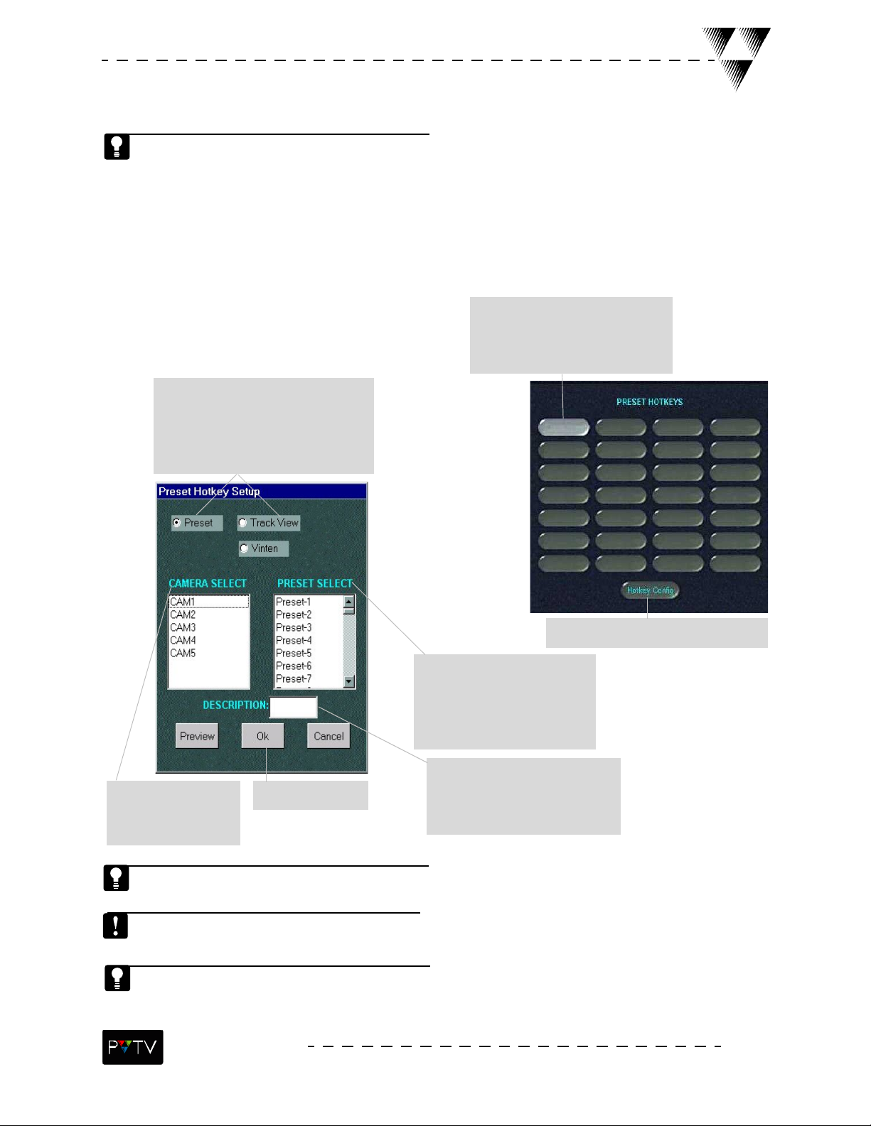
Camera Preset Hotkeys
Camera Preset Hotkeys provide quick recall for preset camera position and autoTRACK™ views.
Each CameraMan® camera can store up to 125 presets in memory through use of the SHOT
Director™. A total of 28 presets can be assigned to the 28 hotkeys in the Preset Hotkeys window
(shown below). Once assigned, these 28 preset hotkeys can recall camera locations and automatic
camera tracking settings.
To assign a hotkey:
3.Toggle the Preset button ON to
recall camera locations OR toggle the
TrackView button ON to recall
autoTRACK presets, including tracking
window and frame offset specifications.
2.Select the desired Preset Hotkey
button. When selected the button
will illuminate. The Preset Setup
dialog box will appear.
1.Select the Hotkey Config. Button.
5.Select the preset number
that corresponds to the preset
in the specified camera. This is
the preset that will be stored in
the selected hotkey.
6.Type a name describing the
4.Select the camera
that contains the preset
to be linked to a hotkey.
7. Select OK.
preset. This name will appear
on the selected preset hotkey
button.
Select Preview after selecting a preset number to view the preset and make sure it is the one
desired before linking it to a hotkey.
The look of the PRESET HOTKEY SETUP dialog box will vary depending on the type of camera
being controlled by STUDIO. Possible camera types include CameraMan, Vinten and/or Radamec.
The Radamec BCP (Basic Control Panel) stores up to 12 presets. The Radamec SCP (Shot Control
Panel) stores up to 600 presets.
STUDIO NEWS
7
Page 12
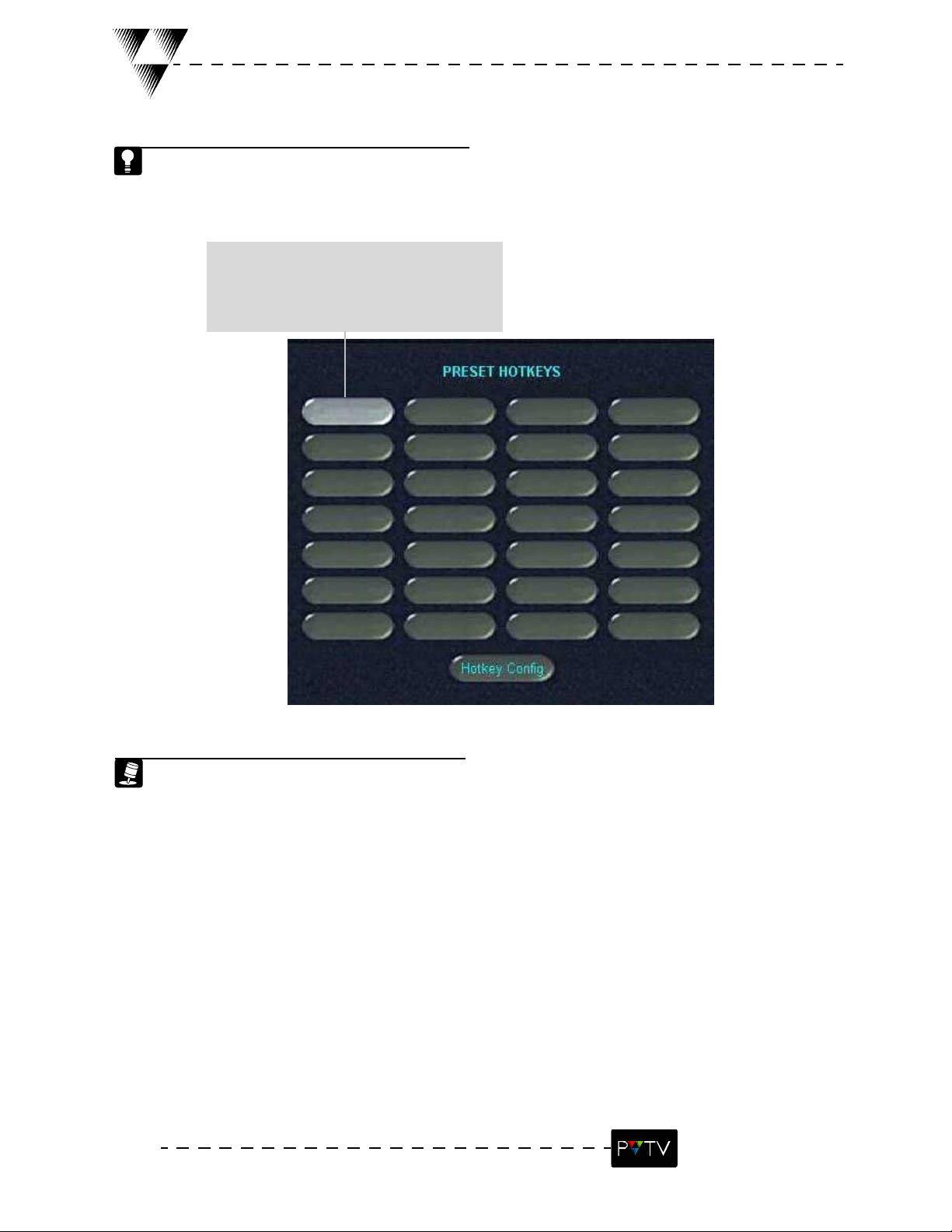
Camera Preset Hotkeys cont’d.
After linking camera locations (presets) or autoTRACK™ settings to the hotkeys, they can quickly
be recalled by selecting the desired hotkey button in the Preset Hotkeys window.
To recall a preset hotkey:
1.Select the desired Preset Hotkey button in
the Preset Hotkeys window. The camera
automatically recalls and moves to the preset
position or setup assigned to the selected hotkey.
Pan Rt.
To recall any of the 125 presets available for each camera, use the
SHOT Director or use the Preset Number drop-down list found in the
Preset Setup dialog box. To get to the Preset Setup dialog box, first select
the Hotkey Config button and then select a hotkey.
8
STUDIO NEWS
Page 13
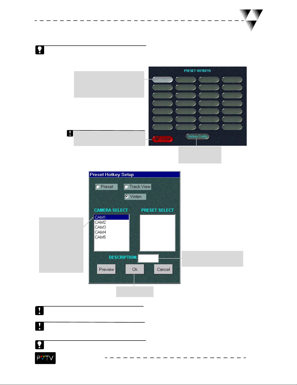
Using the Vinten Camera with PVTV STUDIO NEWS
The following instructions describe how to create a camera preset hotkey using the Vinten system. The Preset Hotkey GUI and Preset Hotkey Setup dialog box are slightly different from those
associated with CameraMan.
2. Select the desired Preset Hotkey
button. when selected, the button will
illuminate. The Vinten Preset setup
dialog box will appear.
Pressing the V Stop button during
operation, stops operation of ALL
Vinten cameras attached to STUDIO.
1. Select the Hotkey
Config. button.
3. Select the appropri-
ate STUDIO-connected
Vinten camera contain-
ing the desired macro.
Once selected, the
VINTEN button in the
top portion of the dialog
box will automatically
be toggled.
4. In the description box, type
in the name of the macro.
5. Select OK.
The look of the PRESET HOTKEY SETUP dialog box will vary depending on the type of camera
being controlled by STUDIO. Possible camera types include CameraMan, Vinten and/or Radamec.
The macro requested in the Preset must be loaded on the Vinten System, otherwise nothing will
happen.
Preview can be selected before selecting OK to make sure the right macro has been chosen.
STUDIO NEWS
9
Page 14
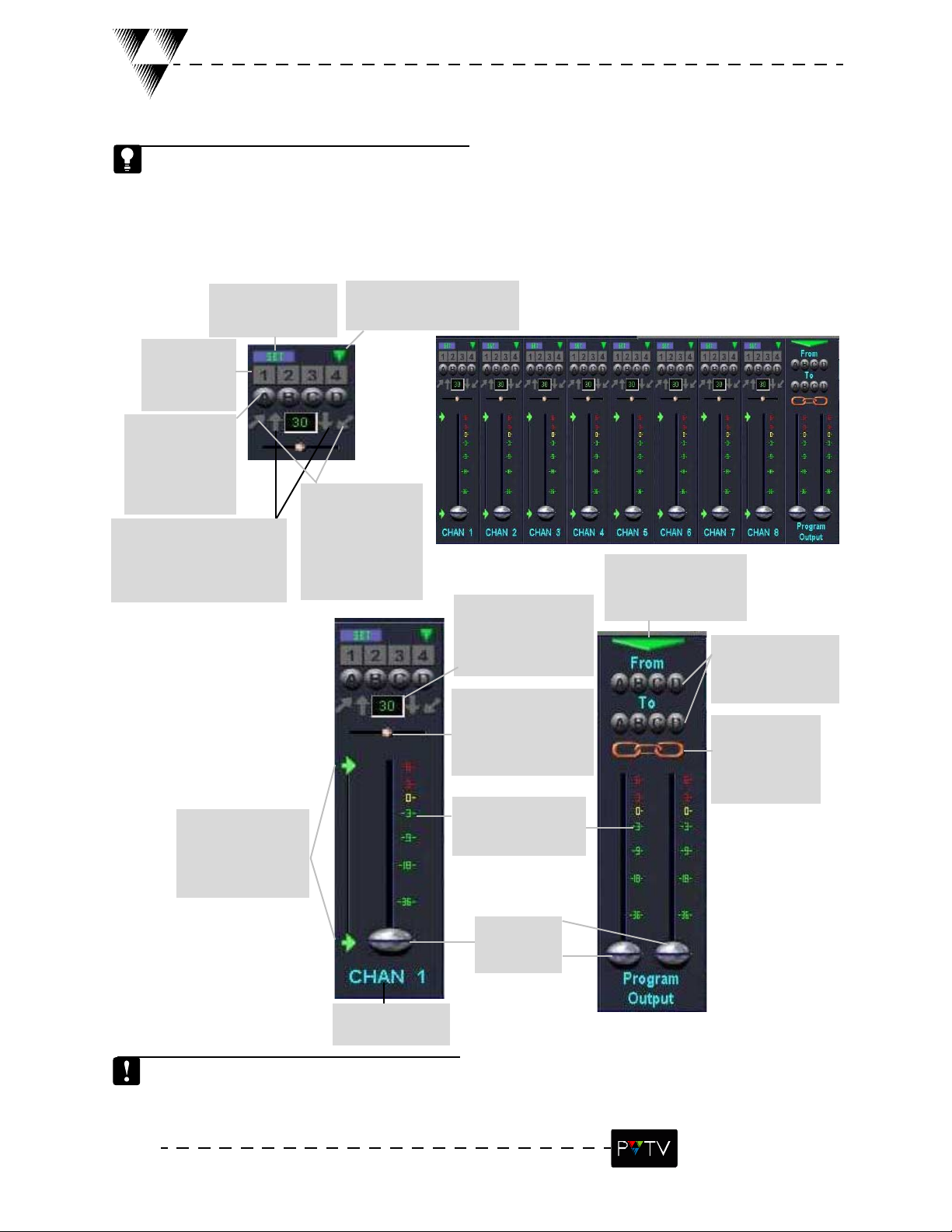
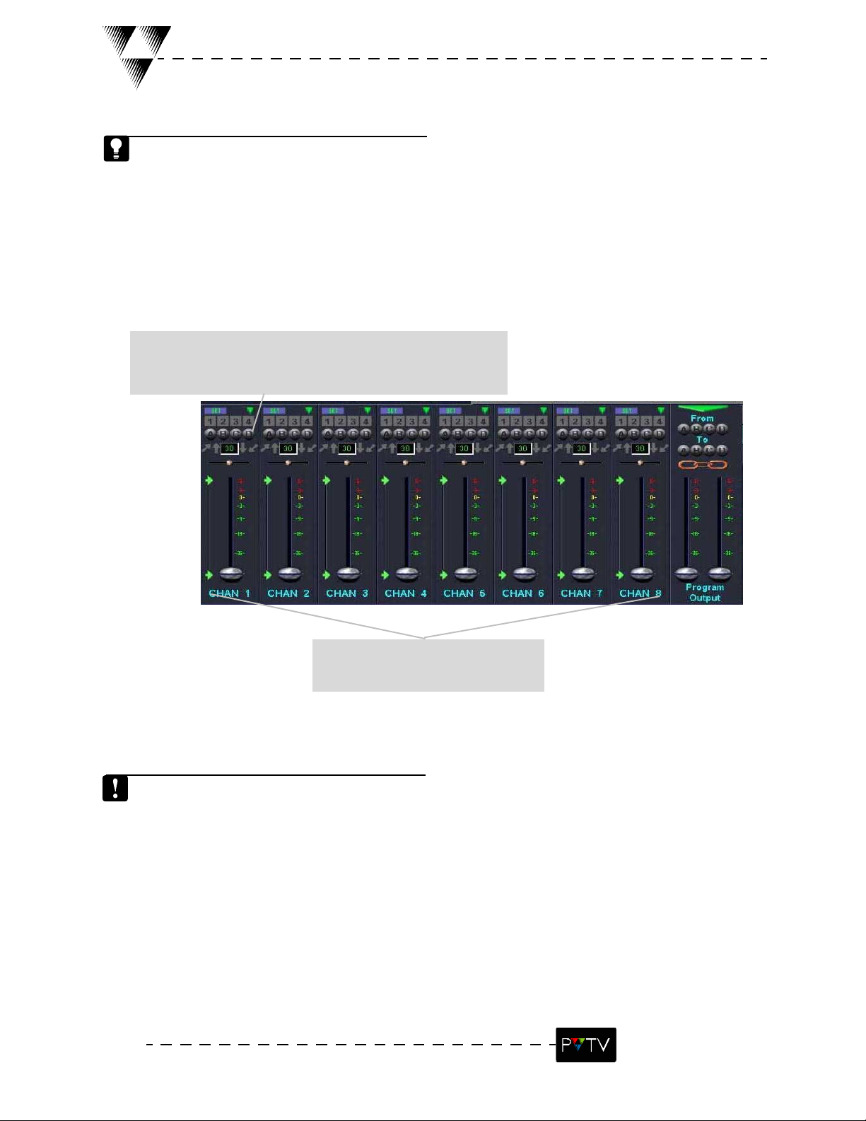
Audio Mixer Overview
The Audio Mixer window allows the control of 16 input, 2 program output, and 5 AUX pre-fade
channels. Input channels 1-8 are displayed on the Audio Mixer Window, but the view can be
switched to display channels 9-16. The illustration below defines the controls found in the Audio Mixer
Window.
Defining the Audio Controls:
Use the Set button
to set the preset (see
page 13).
Use the Preset
buttons (1-4) to
save and recall
audio settings.
Use the Group
buttons (A-D) to
assign faders to a
group. Once
grouped, they will
operate together.
Use the Fade up/down
arrows to auto-fade the
selected channel upward or
downward according to the
duration setting.
Use the Limit arrows
to set
the maximum fade
up/down level
desired.
Use the EQ/AUX button to
access the EQ/AUX Volume
Setup dialog
Use the Cross Fade
up/down
arrows to use the
selected channel/
group as the pri-
mary channel/group
in the cross fade.
Use the Fade Duration
button to set the num-
ber of frames to fade
per second. 30=1 sec-
ond.
Use the Channel
Balance slider to con-
trol the level of left/
right channel input to
the program output.
The VU Meter
indicates the signal
level of each channel.
Use the Mixer Channel
Switch to toggle
between channels 1-8
and 9-16
Use the Cross Fade
Setup assigned
group buttons for
cross fading.
Use the Fader
Link to link/
unlink
the output
volume faders.
Use the Fader
slider to adjust
volume levels.
Audio Channel
Label Description.
If the Broadcast Tools Audio Matrix is installed, an additional button will appear in the upper-right
corner of the PROGRAM OUTPUT section of the Audio Mixer. See page 15 for more information
on Broadcast Tools Audio Matrix.
10
STUDIO NEWS
Page 15
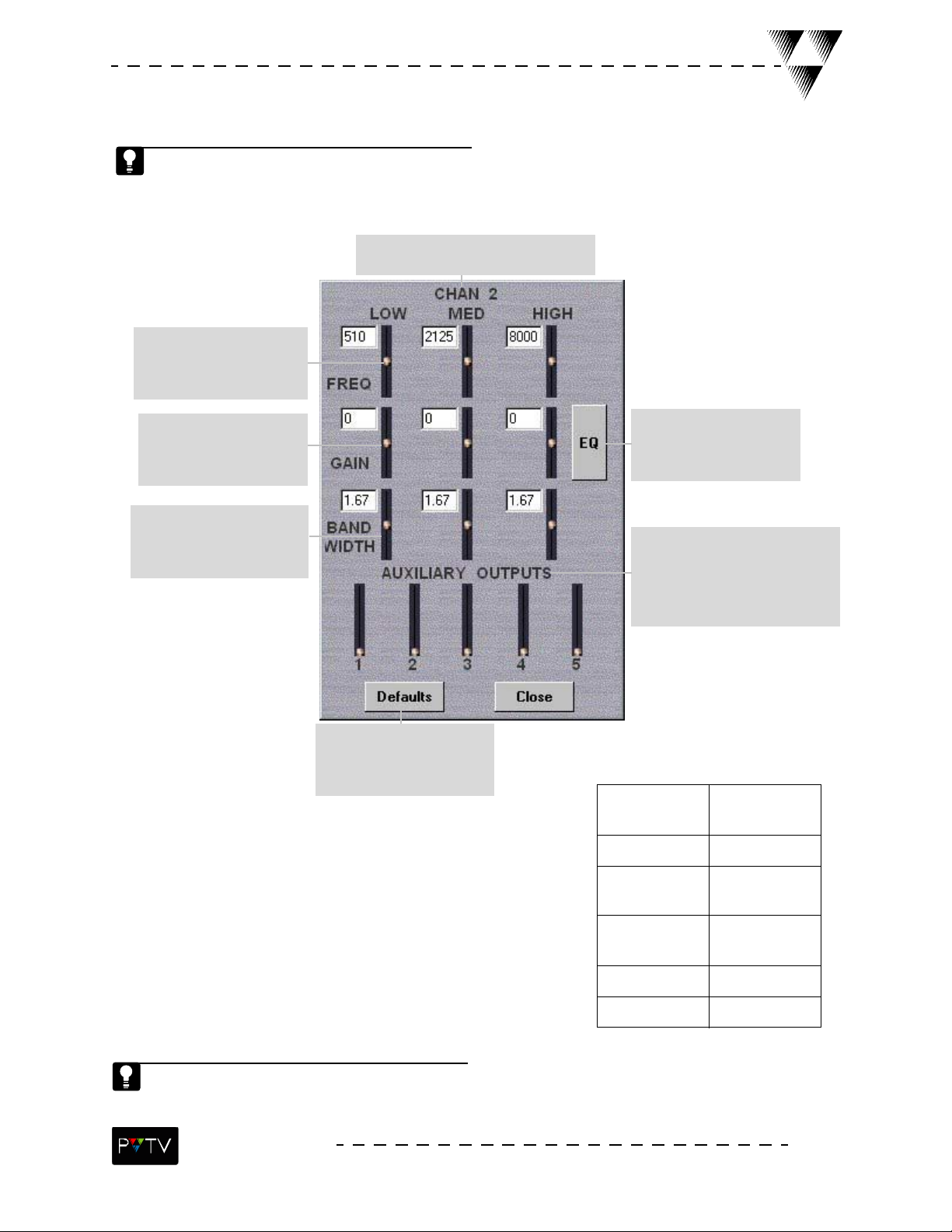
Audio Equalizer and Auxiliary Output Overview
Each PVTV STUDIO NEWS Audio channel has a three-band equalizer to adjust low, medium and
high frequency ranges. The settings in this window are stored and recalled with the preset infor-
mation for each channel.
Specifies which Audio Mixer channel’s
EQ/AUX levels are being controlled.
The Frequency Adjust slider
adjusts the center frequency
of the three audio filters on
the specified channel.
The Gain Adjust slider
adjusts the boost or cut of
the three audio filters on the
specified channel.
The Bandwidth Adjust slider
adjusts the width of the
three audio filters on the
specified channel.
The Default Switch resets all
EQ and AUX faders to factory
default values (shown above).
The EQ/Flat button turns
the equalizer effects on/off.
When the EQ is turned OFF,
the button will say FLAT.
The Auxiliary Output Fader slider
adjusts the volume of the specified
auxiliary output channel. Auxiliary
Output 1 completely controls the
output volume for the specified
channel.
Table 1: Key Frequency
Ranges
Voice Warmth 100Hz - 250
Hz
Voice Clarity 2kHz - 4kHz
Low-mid Mud 200Hz -
Midrange
Honk
Bass Power 50Hz - 100Hz
Treble Air 10kHz - 16kHz
The frequency, gain and bandwidth values indicate the slider position are represented in numeric form in the windows next to the corresponding slider.
STUDIO NEWS
400Hz
800Hz -
1.5kHz
11
Page 16
Assigning Audio Groups
Channel groups set identical parameters for two or more channels. This allows for simultaneous
parameter changes for multiple channels.
To create a channel group:
2.Select the desired group letter (A-D) on the window of the
channel to be included in the group. The button color will
change to indicate that the channel has been included in the group.
1.Determine which of the 16 audio input
channels are to be included in each group.
Repeat step 2 for each of the channels in the group.
Repeat all steps for the other groups.
12
STUDIO NEWS
Page 17
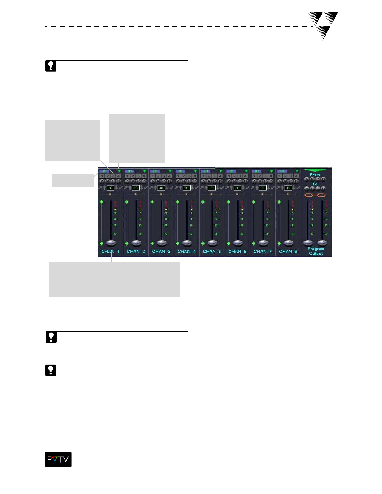
Assigning Audio Presets
Preset buttons allow for quick saving and recalling of audio parameters. each channel has four
preset buttons.
To assign an audio preset:
4. Select a Preset
number (1-4). all speci-
fied audio parameters
are now saved to the
selected preset number.
button to access the
EQ/AUX EQ
and set levels as
desired.
Select CLOSE.
3.Select SET.
1.Set all desired audio parameters for the channel
(volume, balance, min./max fade levels, channel groups)
by manipulating the controls in the desired channel’s
window.
2.Select the EQ/AUX
To label an audio channel, double-click on the channel description label located at the bottom of
the desired channel window, and type the name in the text box that appears. Select OK.
To recall a preset, select the desired Preset button number, and the channel will reflect all saved
audio parameters for that preset.
STUDIO NEWS
13
Page 18
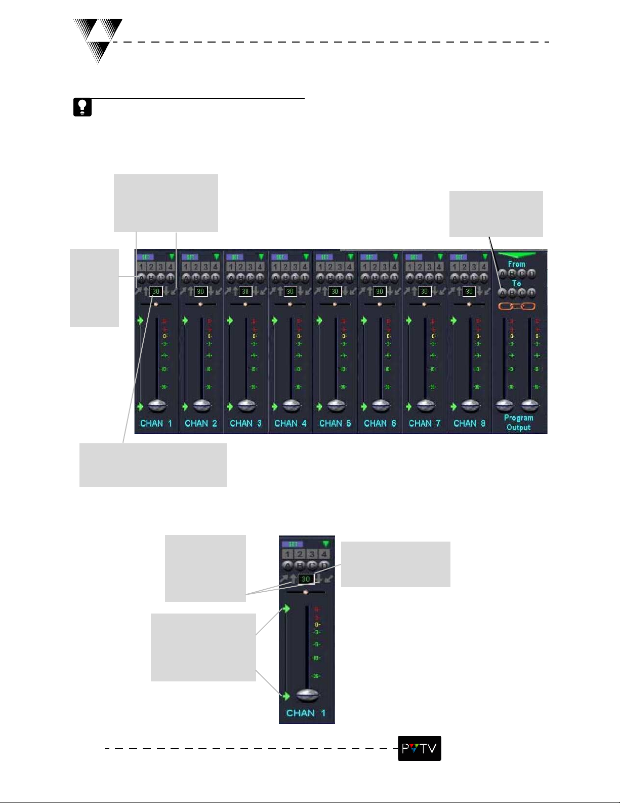
Setting Audio Cross-fades
Cross-fade buttons are used to fade the volume between channel groups. Audio groups must be
established before setting up cross-fades.
To set up an audio cross-fade:
4. Select the cross-fade
up or down arrow to per-
form the cross-fade.
1. Deter-
mine which
groups are
to be used
for the
cross-fade.
3. Select the groups
to cross-fade from and
to.
2. Enter the fade time, which is the
number of frames to fade per second.
The default is 30 frames/second.
Setting Audio Fades
3. Select the fade
up/down arrow to
adjust the volume
up or down.
1. Set the fade min./
max.
levels by sliding the
corresponding arrow to
the desired level.
2. Set the fade time in the
number of frames/second.
14
STUDIO NEWS
Page 19
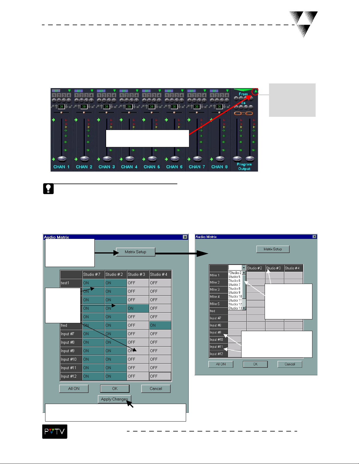
Broadcast Tools Audio Matrix
If Broadcast Tools is connected to STUDIO and configured to a control port, an indicator icon will
appear in the upper-right corner of the PROGRAM OUTPUT section of the Audio Mixer. When selected,
this icon allows access to the Audio Matrix dialog box.
When this Broadcast
tools switch is
selected, the Audio
Matrix dialog box
(below) is opened.
Click here to access the Audio
Matrix dialog box.
The Broadcast Tools switch will only appear on the Audio Mixer if Broadcast Tools is connected to
STUDIO.
The Audio Matrix dialog box allows direct control over the matrix including the ability ot adjust amtrix
options. Defining channel mappings or channel names can only be done by accessing the
Audio Matrix dialog boxthrough selection of the Broadcast Tools switch on the Audio Mixer.
Select MATRIX
SETUP to define
channel mappings or
channel names.
Channels can
be toggled on
or off by
clicking on
the matrix
Select APPLY CHANGES to immediately display changes made to
the matrix.
To ‘MAP’ an output
channel to a STUDIO
audio channel, click on
it, then select the correct
channel from the drop
down list.
To ‘NAME’ an input channel click on
it, then enter the new name in the
EDIT box. This name will appear
under the specified audio channel on
the GUI.
STUDIO NEWS
15
Page 20
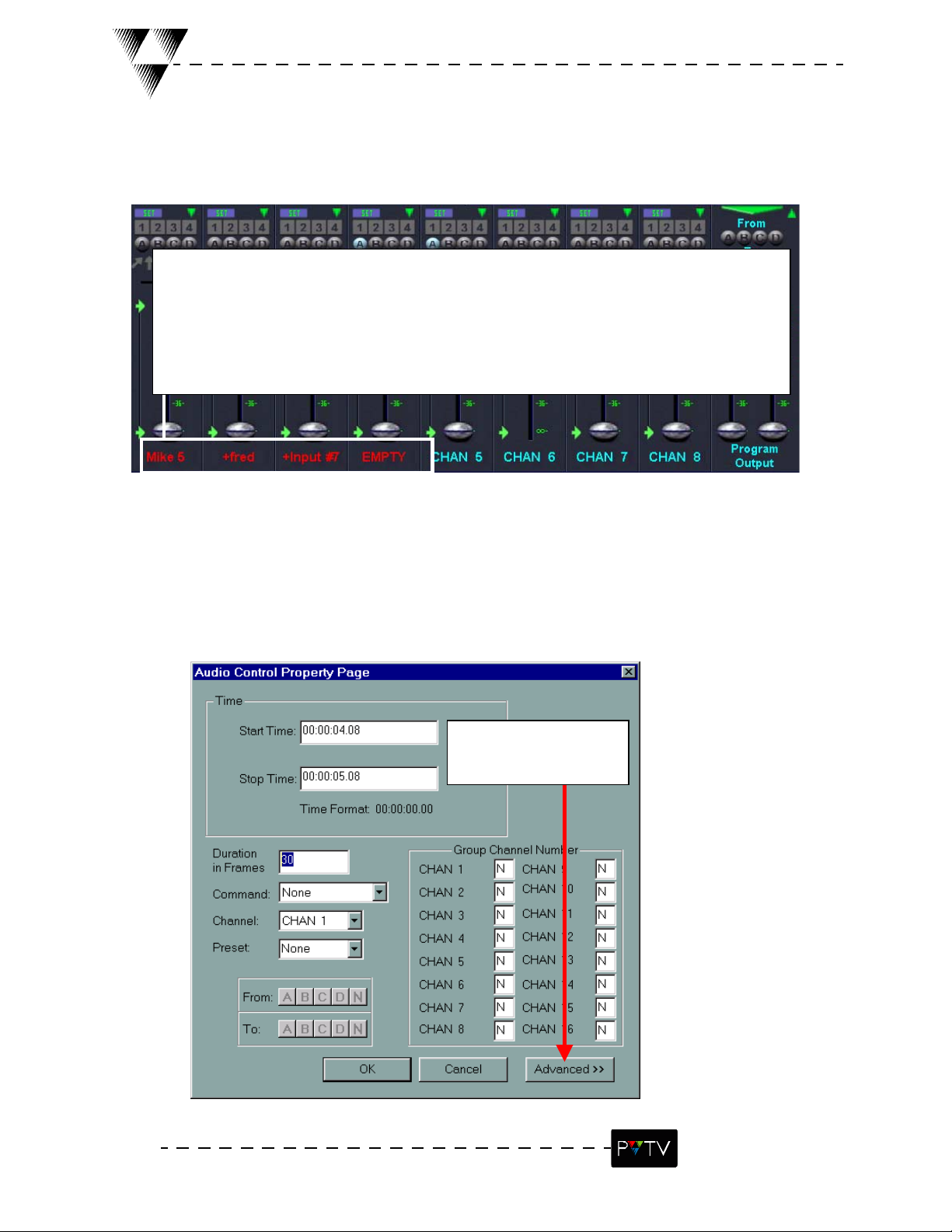
Broadcast Tools Audio Matrix
As the matrix selections change, the audio channel names will vary to reflect those
changes.
1. EMPTY – No channel selected.
2. Name – the name given the channel in Matrix Setup.
3. (+) – Name preceded by a plus sign means that more than one channel is selected
Note: To help prevent confusion, do not name any of your matrix channels “Empty”
Selecting the ADVANCED option on the Audio Control Property Page (below), which is accessed by
double-clicking a macro command on the timeline (see the section entitled, “Macro Command Property
Pages”), also opens the Audio Matrix dialog box. However, when the Audio Matrix is accessed this
way, channels can only be toggled ON/OFF. No channel mapping or naming can be done from this
area.
16
Click here to define the
Audio Matrix for the
macro.
STUDIO NEWS
Page 21
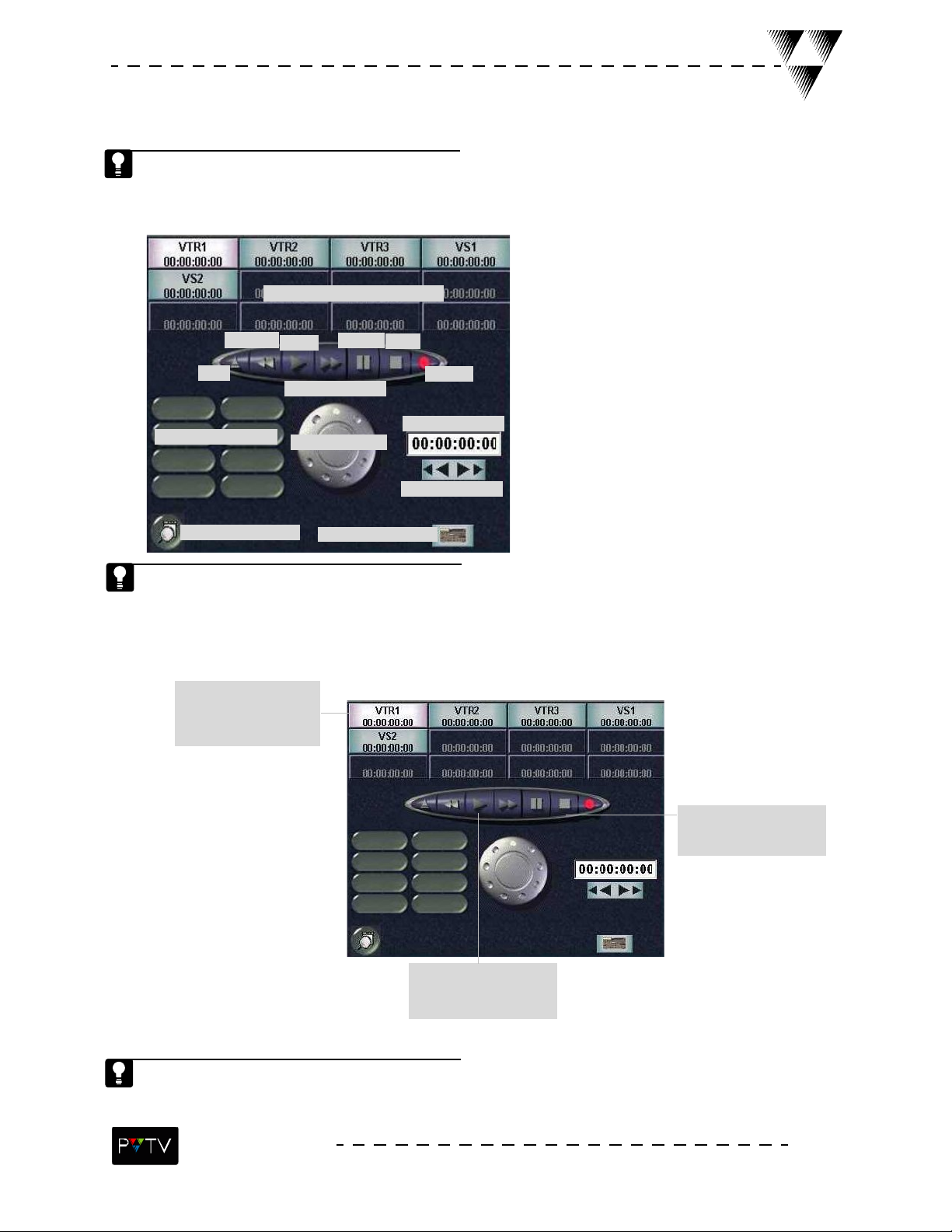
VTR Control Interface Overview
The VTR (Video Tape Recorder) is the area of the Digital Control GUI where all STUDIO-connected
VRs and VTRs are controlled. The VTR can play and record videos, playback preset segments, and
scan and shuttle videos.
Machine Control Interface
Rewind
Eject
VTR Play Segments
Set Preset Button
Play
Pause
Fast-forward
Shuttle Knob
VTR Setup Button
Stop
Record
Time Code Box
Search Button
When the VTR Setup Button (in the lower-right corner of the VTR Control Interface) is selected,
the VTR Setup dialog box opens. VTR settings can be adjusted from this dialog box.
To play back a video:
1. Select a STUDIO-
connected VTR to
control.
3. Select the STOP
button to stop playback.
2. Select the PLAY
button to begin playback.
Use the shuttle knob (by dragging the mouse to the left to rewind or to the right to fast-forward)
to scan a video and locate a particular frame. This can be done while viewing the video on the
monitor.
STUDIO NEWS
17
Page 22
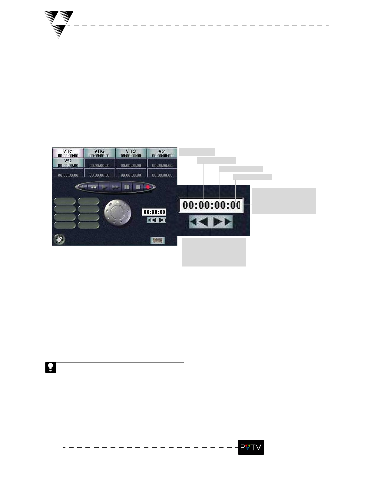
To search for a specific time code:
Using VTRs in PVTV STUDIO NEWS
Hours 0-23
Minutes 0-59
Seconds 0-59
Frames 0-29
1. Enter the desired
video time code in the time
code box.
2. Click the search button
to fast-forward or rewind to
the specified time code.
The Machine Control Interface allows STUDIO to control up to twelve
external devices (VTRs, VRs, etc.).
18
STUDIO NEWS
Page 23
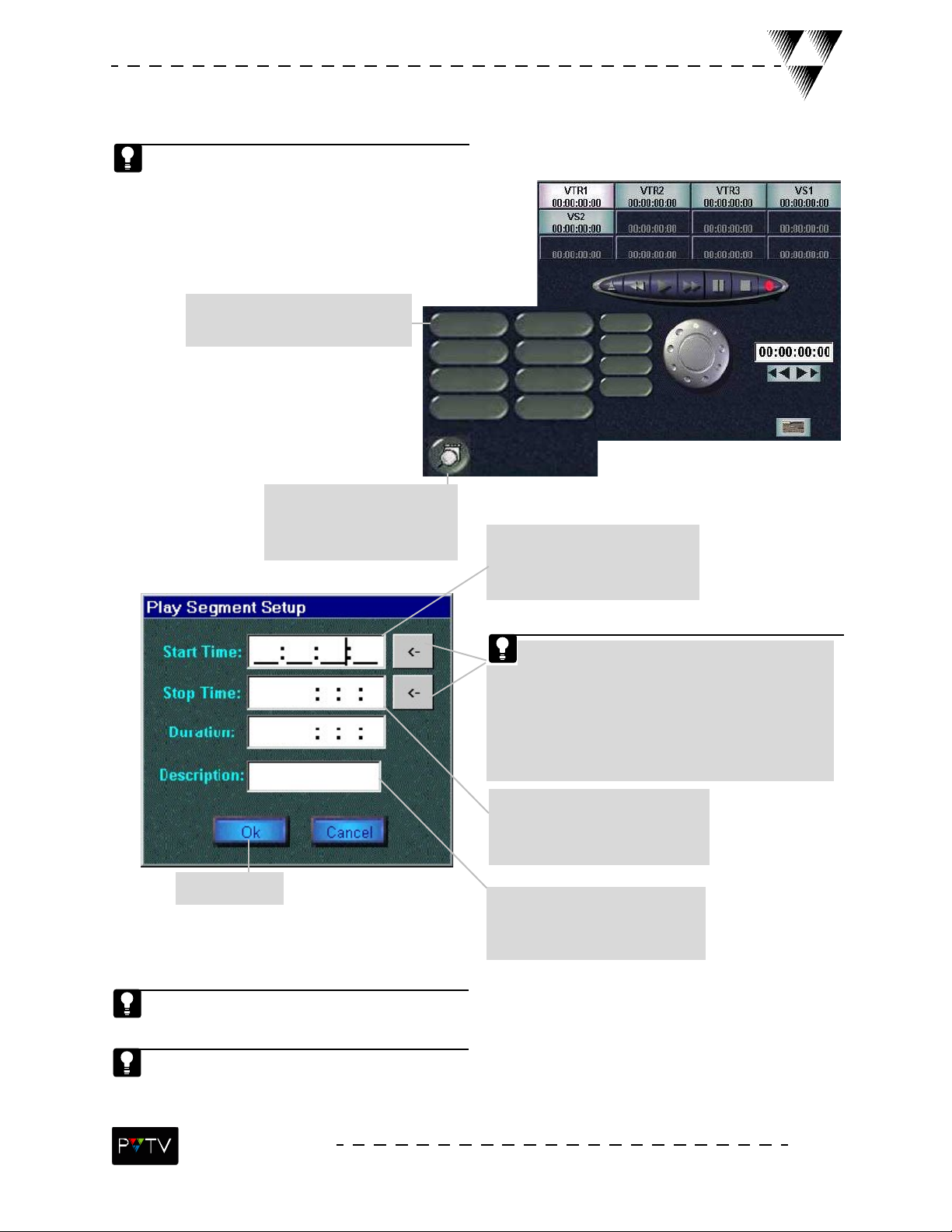
Setting Up VTR Play Segments
The VTR Interface provides 8 play segment buttons for each STUDIO-connected VTR.
1. Select a blank Play Segment
Preset button.
2. Click the Set Pre-
set button. The Play seg-
ment Setup dialog box
3. Enter a start-time time
code that corresponds with
the desired play segment.
Use the VTR controls to locate the begin-
ning time code. Once found, click the
arrow next to the Start-Time box. Then use the
VTR controls to locate the ending time code,
and click the arrow next to the Stop-time box.
The codes will be entered into the Start/Stop
Time boxes.
4. Enter a stop-time timecode
that corresponds with the
desired play segment.
6. Select OK.
Leave the Duration blank and it will calculate automatically, or enter a duration,
leaving the stop-time blank, and the stop-time will be calculated automatically.
To edit or review a saved play segment, select the desired Play Segment Preset
button, click the Set Preset button, clear or edit existing properties, and select
OK to save changes or Cancel to discard changes.
5. Enter the name to appear
on the Play Segment Preset
button.
STUDIO NEWS
19
Page 24
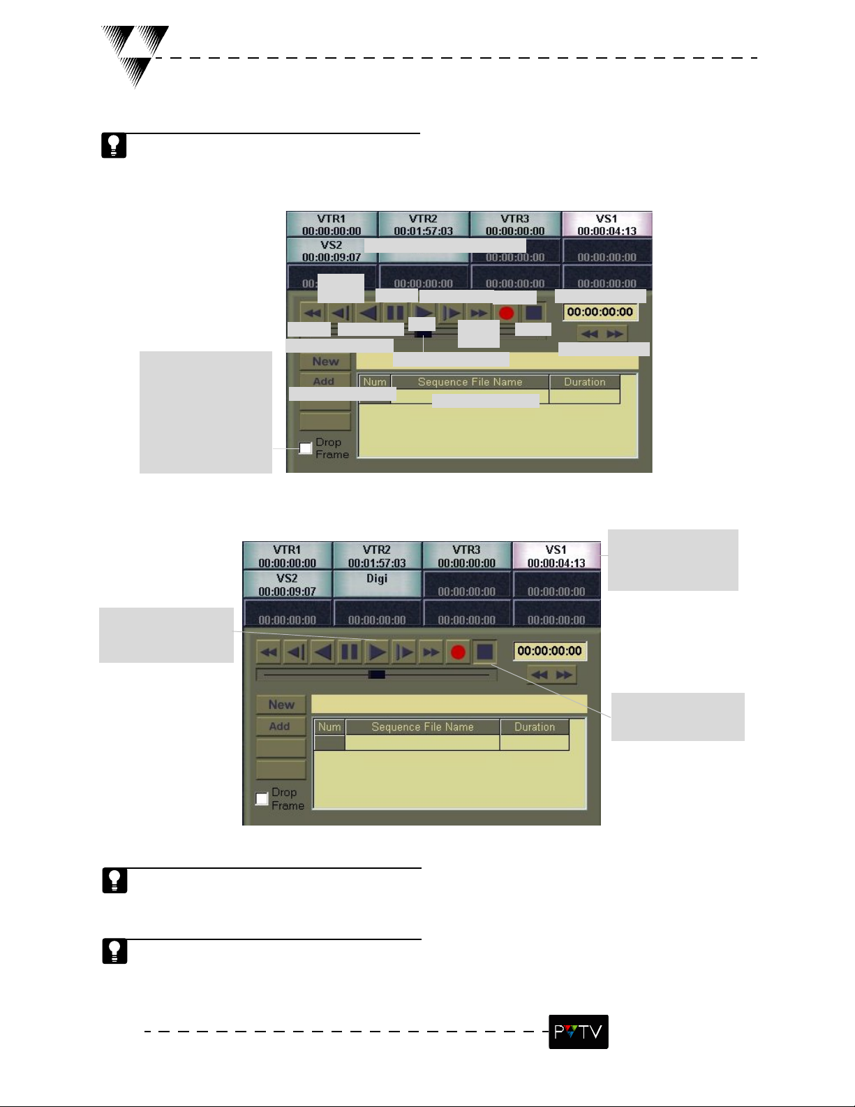
VR Control Interface Overview
The VR (Virtual Recorder) is the area of the Digital Control GUI where all STUDIO-connected VRs
and Video Servers are controlled. The VR can play and record video segments, playback saved file
segments, and control jog, scan or shuttle segments.
Machine Control Interface
Reverse
Play
Pause
Forward Jog
Record
Time Code Box
When selected, two
frames are skipped at the
beginning of each
minute, except for every
tenth minute, so that the
frame value for time
codes matches that for
real time.
To play back a segment:
2. Select the PLAY but-
ton to begin playback.
Rewind
Create a new file
ADD a file to the list
Reverse Jog
Play
Shuttle/Scan Slider
Fast-for-
ward
Segment File List
Stop
Search Button
1. Select a STUDIO-
connected VR to con-
trol.
3. Select the STOP
button to stop playback.
Use the shuttle/scan slider (by dragging the mouse to the left to rewind or to the right to fast-forward) to scan a segment and locate a particular frame. This can be done while viewing the seg-
ment on the monitor.
Reverse jog and Forward Jog, rewind/fast-forward the segment 1 frame at a time. Reverse Play
plays the segment in reverse mode while maintaining normal playback speed.
20
STUDIO NEWS
Page 25
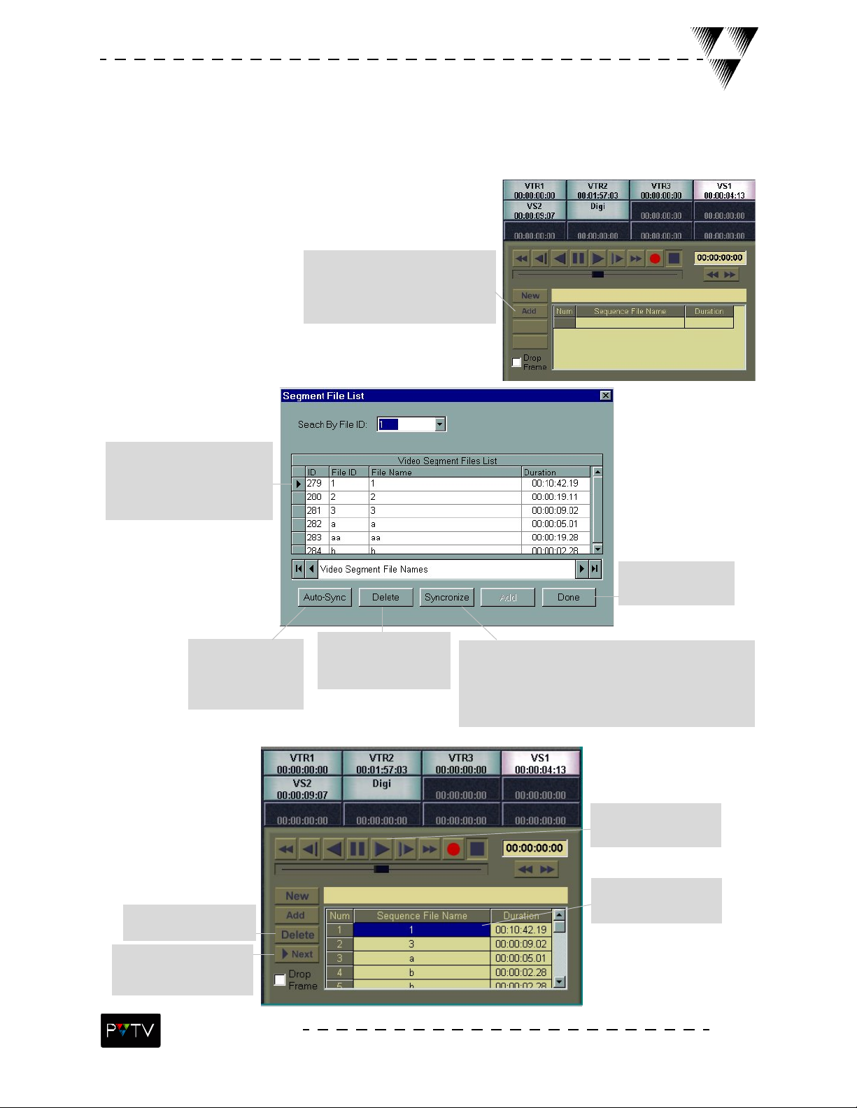
Setting Up VR File Segments
To add a file to the segment list and play it back:
1. Select the ADD button on
the VR Control Interface. The
Segment File List dialog box
appears.
2. Select and double-click the
video file(s) to be added to the
segment list (below).
Automatically
lists segment
files found on
the server.
Deletes a file from
the segment list.
Highlights the next
file in the segment
list.
Deletes the selected
file from the
STUDIO data base.
3. Select DONE
when finished.
User interaction is required to decide which
files will be included in the Video Segment
Files list. When many files are contained on
the server, the synchronization process can be
tedious.
5. Select the play
button.
4. Double-click the
file to be played.
STUDIO NEWS
21
Page 26
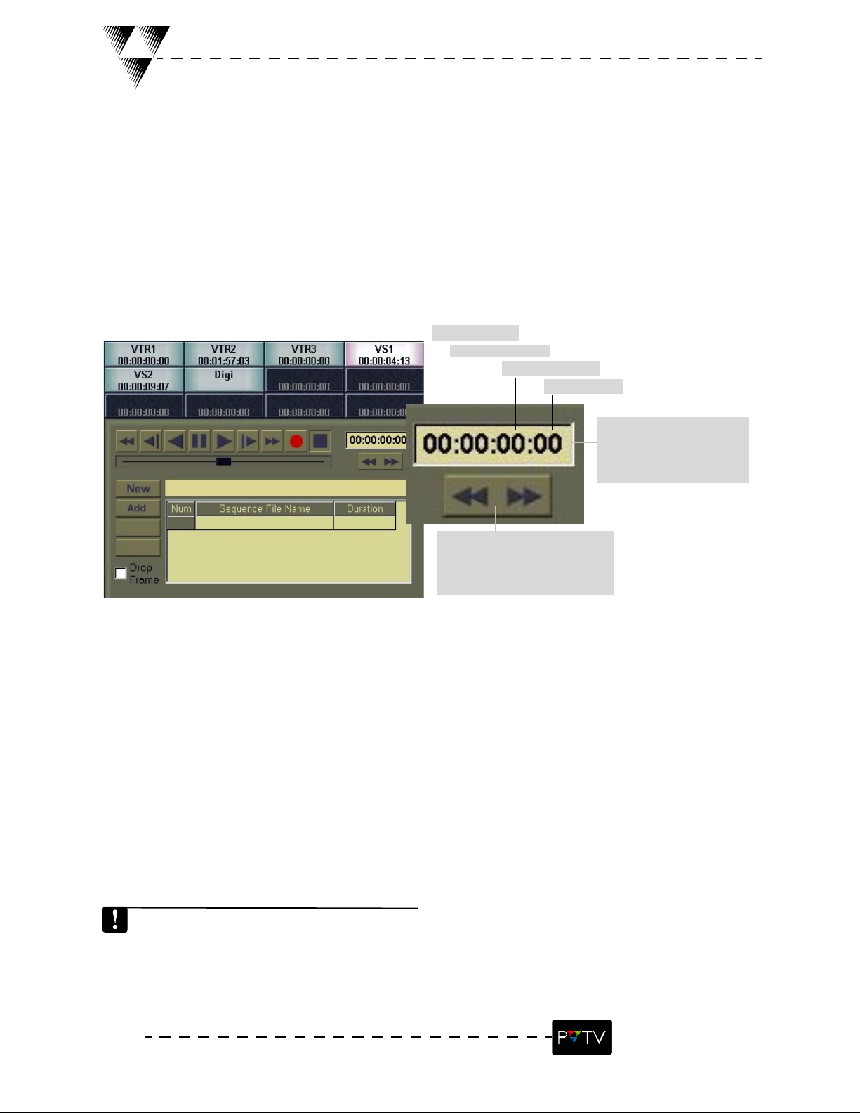
To search for a specific time code:
Using VRs in PVTV STUDIO NEWS
Hours 0-23
Minutes 0-59
Seconds 0-59
Frames 0-29
1. Enter the desired
segment time code in the
time code box.
2. Click the search button
to fast-forward or rewind to
the specified time code.
The VR search function will only search the loaded segment file.
22
STUDIO NEWS
Page 27
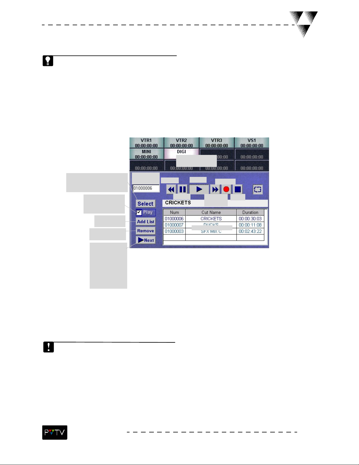
Audio Server Interface Overview
The Audio Server is the area of the Digital Control GUI where all STUDIO- connected audio servers
are controlled. The Audio Server can play and record audio files, playback previously saved files,
and rewind, fast-forward and continuously play audio files.
Machine Control
Interface
Used to drag and drop
audio macros onto the
Transition Macro Timeline.
Automatically
selects and plays
the audio file.
ADDS a file to
the list
Deletes a file
from the list
Loads the next
file in the list. If
the AUTO PLAY
box is selected,
the NEXT but-
ton will load and
play the next file.
Selected file
ID #
Rewind
Pause
Play
Fast-for-
ward
Audio file list
Record
Stop
PVTV STUDIO NEWS currently supports Digicart and Sony Mini-Disk audio servers.
STUDIO NEWS
23
Page 28
Setting Up Audio Files in PVTV STUDIO NEWS
To add a file to the Audio File List and play it back:
1. Select a STUDIO-
connected audio
server on the Machine
Control Interface.
2. Select Add List.
The Audio Server Cut
List dialog box opens.
3. Double-click the
audio file(s) to be added
to the audio file list.
Lists audio files found
on the server.
4. Select OK when
finished.
6. Select the play
button.
5. Double-click the
file to be played.
Digicart may contain multiple file directories. Each of these may contain various files. To select a
different directory, use the drop-down menu on the lower portion of the Audio Server Cut List
dialog box.
An audio file can also be played by first checking the play box on the left and then the select button.
24
STUDIO NEWS
Page 29
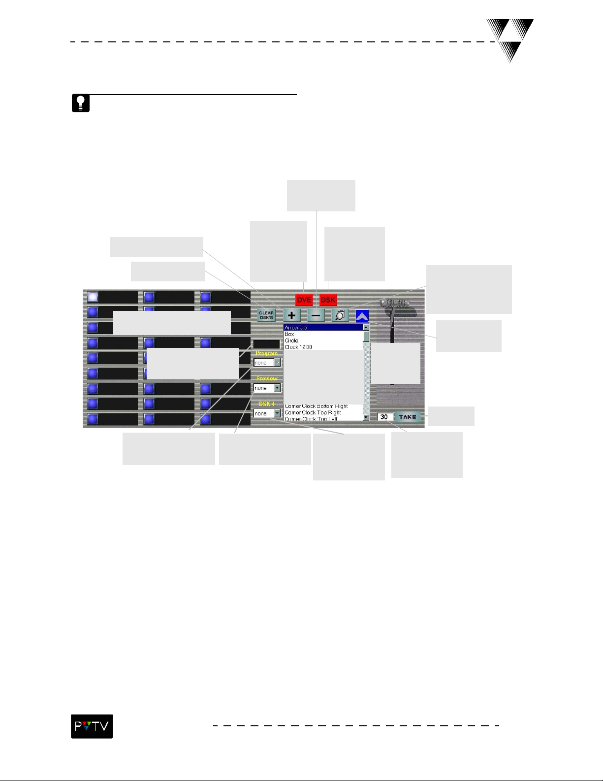
DVE Interface Overview
The PVTV STUDIO NEWS Digital Video Effects (DVE) system creates transitions from wipe and
fade effects. These effects transpose video images from different input devices (character generators and still stores, etc.). Transitions include DVE and Process Effects, which give full control over picture position, shape, luminance, chromakey, luma/DSK key and motion.
Deletes settings
from the selected
preset button.
Opens the dialog box to
build a transition.
Resets the external
DSKs (2-4) to none.
Select a DVE Preset hotkey to
store or recall an effect.
Indicator telling which
keyed source is on the
program channel.
Tells which keyer is cur-
rently active on the pro-
gram channel.
The DVE Feed-
back LED indi-
cates whether
the DVE layer is
turned on or
off.
Select a wipe/fade or
sequence transition
from the Transition
List to display the
transition’s setup box.
Tells which keyer is currently active on the pre-
view channel.
The DSK Feed-
back LED indi-
cates whether
the DSK layer is
turned ON/OFF.
The Take Bar
is controlled
Downstream of
Program and Preview. Selects the
source to fill DSK 4.
Displays the setup dia-
log box for modifica-
tion and editing of
the selected
transition.
Indicates which
transition is
selected.
with the
mouse
Use for
auto-takes.
Take Duration is
registered in
frames, with 30
frames = 1 second.
Three types of dialog boxes are used in succession to refine and characterize transitions:
1. Transition Setup dialog box: appears when a transition is selected from the transition list on the
main DVE interface. Use this to set properties of the transition.
2. DVE Setup dialog box: Appears when a DVE effect is selected from the DVE list on the Transition
Setup dialog box. Use this to set the DVE properties.
3. Process Effects dialog box: Appears when a process effect is selected from the process effects
list on DVE setup dialog box. Use this to set the properties of a process effect.
STUDIO NEWS
25
Page 30

Transitions Overview
Video transitions are created from a wipe, fade or sequence effect that transposes two video
images from two different external devices, such as cameras or VTRs. A transition can include
additional effects such as DVE and Process effects. After selecting a transition from the Transition List
on the DVE interface, the following Transition Setup dialog box appears.
To open the DVE
Select Back-
ground to
change the
background
with the transi-
tion.
Select DVE ON
to turn on the
DVE layer with
the transition.
Select DSK ON
to layer with the
transition.
Toggle to select
the layer to be
on top.
Adjust the slider controls to
personal specifications.
Toggle to select
a one or two-
sided DVE.
Setup dialog box,
select the desired DVE
effect from the DVE
Select to close
and cancel.
Resets settings
to what
appeared when
the dialog box
was first
opened.
Resets dialog
box settings to
system defaults.
Select OK when
finished.
There are four main types of transitions:
1. Wipe: Switches from one picture to another by moving a geometrical form (circle, line, arrow)
through the screen.
2. Fade: Dissolves a full picture to a black screen (Fade-out), or a black screen to a full picture (Fade-
in). a Cross-fade involves two pictures, one that fades in while the other fades out.
3. Mix: A Wipe or Fade combined with a DVE image. Process Effects are used to define and charac-
terize the DVE content.
4. Cut: One image is switched to another instantaneously.
26
STUDIO NEWS
Page 31

DVE Setup Dialog Box Overview
A dialog box similar to the one below appears when a DVE is selected from the DVE List on the
Transition Setup dialog box.
Select a Process Effect to change
the content or position of the
DVE image.
Select to close
and cancel.
Resets settings
Scroll/toggle to
define size and
shape of the
Page Turn.
Adjust the slider controls to
personal specifications.
Toggle to define
how light will be
seen on the page
turn.
to what
appeared when
the dialog box
was first
opened.
Resets dialog
box settings to
system defaults.
Select OK when
finished.
The available options on this dialog box change depending on which DVE is
selected from List on the Transition Setup dialog box.
Process Effects Setup Dialog Overview
The Process Effects dialog box appears when the Process Effects Menu is selected from the DVE
Setup dialog box. After selecting the desired process effect, a corresponding dialog box will
appear.
Select the Process
effect to be used. This
will open another dia-
This additive feature
shows all Process
effects that are cur-
rently turned ON.
Select the appro-
priate time to
clear process
effects.
log box.
STUDIO NEWS
27
Page 32

28
STUDIO NEWS
Page 33

DVE Sequencer Dialog Box Overview
A sequence links multiple DVE images to produce continual motion effects. For example, two or
more DVE images set at different coordinate points produce a sequence that moves the image
across the screen from one point to another. If different DVE images or shapes are used, such as a
page turn or warp effect, the sequence transforms the images from one shape to the next.
Automatically displays
The Key Frame Icon indicates that
a sequence is being built. It
appears after settings are defined
in the Sequence Setup dialog box.
the first available cache
memory slot where the
sequence will be stored.
There are a total of 24
slots.
Sequencer
Timeline
The Cancel command closes without saving current
Sequencer Timeline.
OK closes and saves
current Sequencer
Timeline settings.
The Key Frame Setup but-
ton displays the DVE
Clears DVE
Sequencer
Timeline.
The ADD but-
ton adds a keyframe to
the Sequencer Timeline
based on current settings in the Sequence
Setup dialog box.
setup dialog box.
The DELETE button
deletes the current
key frame from the
Sequencer Timeline.
Opens the Sequence
Setup dialog box for
the selected Key
Frame.
sequence
into current
cache slot of
the DVE.
Stop
Load
The Loop Control, Count and slider functions found at the bottom of the DVE
Sequencer box are nonfunctional at this time.
Cue
Saves current
sequence to
the DVE.
Reverse
Play
Deletes a
folder
Deletes a
file.
Loads a
sequence
saved on
the com-
puter.
Saves a
sequence to
the computer.
STUDIO NEWS
29
Page 34

Building a DVE Wipe/Fade Hotkey
1. Select a blank
hotkey. When
selected, the key
will illuminate.
3. Select the + (plus) key to
add that transition to the hotkey. This will open the Transi-
tion Setup dialog box.
5. Adjust the faders to obtain
2. Select a Wipe/
Fade transition
from the transition
list.
desired effect.
4. Select Back-
ground to change
the background
with the transition.
30
6. Select OK. The
DVE Hotkey will
save settings.
STUDIO NEWS
Page 35

Building a Fixed Position DVE Hotkey
1. Select a blank
hotkey. When
selected, the key
will illuminate.
3. Select the + (plus) key to
add that transition to the hotkey. This will open the Transi-
tion Setup dialog box.
2. Select the
Fade transition
from the transition
list.
5. Double-click the desired DVE
Effect (example: Warp). The DVE
Setup dialog box appears.
4. Select DVE ON.
6. Select the
desired effects
and attributes for
the DVE.
7. Use the sliders to manipulate the position of the DVE, in
this case, Warp.
8. Select OK. The DVE
Hotkey will save settings.
STUDIO NEWS
31
Page 36

Building a DVE Sequencer Hotkey
1. Select a blank
hotkey. When
selected, the key
will illuminate.
3. Select the + (plus) key to
add that transition to the hotkey. This will open the Transi-
tion Setup dialog box.
2. Select the
Fade transition
from the transition
list.
32
5. Select the key to signal the building
of the sequence, and open the Wipe/Fade
dialog box.
4. Select the number for the sequence.
24 sequences can be saved in memory.
The DVE Sequencer displays the first avail-
able slot when opened.
STUDIO NEWS
Page 37

6. Select DVE ON.
Building of DVE Sequencer Hotkey cont’d.
7. Double-click the desired DVE
Effect (example: Warp). The DVE
Setup dialog box appears.
8. Click on Process effects and then
select the option to Clear all Process
Effects.
9. Use the Position and Radius OR Angle sliders to
set the first position of the Page Turn. For the first
position, normally the sliders are left defaulted.
10. Select the + (plus) sign
on the DVE Sequencer. This
will open the Sequence Setup
dialog box.
STUDIO NEWS
33
Page 38

Building a DVE Sequencer Hotkey cont’d.
Although the other controls in
this dialog box can be
adjusted, they are normally left
at their default settings.
11. Choose the interpola-
tion, or type of key frame tran-
sition.
12. Select OK. The Sequence
Setup dialog box will close and a
key frame will be added to the DVE
Sequencer Timeline.
13. If the other dialog boxes
have been closed, select the key
again to signal the building of
the sequence, and open the
Wipe/Fade dialog box.
34
STUDIO NEWS
Page 39

Building a DVE Sequencer Hotkey cont’d.
14. Use the Position and Radius and/or Angle sliders to set
the second position of the Page Turn. For the second position,
normally the position slider is pushed all of the way up.
15. Select the + (plus)
sign on the DVE Sequencer.
This will open the Sequence
Setup dialog box.
16. Choose the interpo-
lation, or type of key frame
transition.
17. Select OK. The Sequence
Setup dialog box will close and a key
frame will be added to the DVE
Sequencer Timeline.
STUDIO NEWS
35
Page 40

Building a DVE Sequencer Hotkey cont’d.
18. Select OK on the
Page Turn dialog box.
20. Select OK on the
DVE Sequencer dialog box.
All dialog boxes must be closed in succession, with the last one opened being the
first one closed.
Once all dialog boxes have been closed, the selected hotkey will reflect the
sequence that was just created and stored.
36
19. Select OK on the
Wipe/Fade dialog box.
STUDIO NEWS
Page 41

To delete a transition:
Deleting and Editing Preset Hotkeys
1. Select the
desired hotkey.
When selected, the
key will illuminate.
To edit a transition:
1. Select the preset
hotkey to be edited.
2. Select the - (minus) key. This will
delete the saved settings assigned to
the selected hotkey.
2. Select the magnifier
to display the Setup dia-
log box.
To access the DVE previously selected with the transition, double-click the DVE
highlighted in the DVE list box. To switch to another DVE, double-click on the
desired DVE. A message box confirming the change will be displayed.
STUDIO NEWS
37
Page 42

1. Select the transi-
tion to take (play).
Taking a Transition
2. Set the transition speed
by entering the number of
frames per second (30
frames = 1 second).
3. To manually take the
transition, drag the take bar
downward. To auto-take the
transition, click the Take but-
ton.
38
STUDIO NEWS
Page 43

Digital Video Effects
Corner Pin
Corner Pin allows for the movement of each corner of the image independently and along the
specified axis.
Turns the image along the X-
or Y-axis starting at the top-
right corner.
Turns the image along the X-
or Y-axis starting at the top-
left corner.
Twists the image hori-
zontally (X-Twist) or
vertically (Y-Twist).
Drop Shadow
The Drop Shadow Effect creates a basic flat file with a shadow. The Drop Shadow can only be
seen if the DVE is sized appropriately.
Turns the image along the X-
or Y-axis starting at the bot-
tom-left corner.
Turns the image along the X-
or Y-axis starting at the bot-
tom-right corner.
Determines the sharpness of
the twist of the image as it
moves the midpoint along the
axis.
Cancel
Undo
Load
Defaults
OK
Moves the shadow
along the X- or Y-
Determines the pat-
tern of the interior
shadow.
STUDIO NEWS
Determines the size
of the shadow.
axis.
Determines the color
of the shadow based
on a scale of 0-255.
Uses the black and white por-
tion of the video signal to
determine brightness.
Controls how
much of a given
hue is applied.
Controls the level
of transparency of
the shadow.
Cancel
Undo
Load
Defaults
OK
39
Page 44

DSK Linear Keyer
Determines the
pattern of the
interior of the
key signal.
When INVERT is
toggled, it
inverts or
reverses the DSK
key signal.
Linear Mode uses
the DSK signal with
normal f unctiona lity.
In sliced mode, the
key is altered.
Toggle to get the syncs
for the key from the key
signal. Toggle DSK
Video to get the syncs
for the key from the
video signal.
When on, Freeze
Flag freezes the
current picture,
when off, the
current picture
passes as normal.
Increases the key
signal by 1.85% at
Modifies the key
source picture. All
four sides can be
modified.
entire frozen frame or
input.
Digital Video Effects
Adjusts contrast between back-
ground and key source, scales
the amplitude of the key signal
and adjusts position of the key
source.
Cancel
Undo
Load
Defaults
OK
Displays either the
only the first field of
the frozen frame.
Dual Channel
Dual Channel simultaneously displays two independently controlled images (tiles).
Rotates the angle of the tile horizontally,
vertically, or along the line of sight.
Moves the tile horizontally, verti-
cally, or along the line of sight.
Scales the image horizontally,
vertically, or in both directions.
Prop-
erty
changes
are
applied
to the
selected
tile.
Select which tile will be
the top layer.
Determines the texture of the
edges of the selected tile.
Rotates the tile around the horizontal or
vertical axis, or the line of sight.
Determines the rate at which the
tile rotates horizontally, verti-
cally, or along the line of sight.
Cancel
Undo
Load
Defaults
OK
40
STUDIO NEWS
Page 45

Digital Video Effects
DVE Wipe
Select the direction
that the video source
will be wiped off the
page.
Determines whether the diag-
onal wipes are at 45 degrees
(square) or pass through the
corners of the screen (Screen).
Adjusts the width
of the existing
border.
Controls the actual
progression
through the effect.
Uses the black and
white portion of the
video signal to deter-
mine brightness.
Determines the color
of the wipe on a scale
from 0-255.
Controls how much
of a given hue is
applied.
Cancel
Undo
Load
Defaults
OK
External Chroma Keyer
The External Chroma Keyer and External DSK Keyer (next page) are external to the system and
allow for multiple layers of keys. They are only functional with use of the Leitch DSK 6801 and
6803.
Selects
which keyer
is being controlled (1-3).
Determines the amount of light
admitted allowing the object
behind to be seen.
Determines the steep-
ness of the keyer.
Lists all video inputs
available in STUDIO.
Determines the bright-
ness and color depth
to be rejected by the
keyer.
Sets the angle around
the specified Hue for
which the key will be
generated.
Cancel
Undo
Load
Defaults
OK
STUDIO NEWS
41
Page 46

External DSK Keyer
Determines the clipping
point of the keyer.
Digital Video Effects
Determines the steep-
ness of the keyer.
Determines the amount of
light admitted allowing the
object behind to be seen.
Cancel
Selects
which keyer
is being controlled (1-3).
Fragment
Controls the actual progression
through the effect. At 0%, the tile
is completely together, at 100%, it
Determines
where on the
screen the
fragment will
begin.
Determines
how many
squares/strips
the fragment
will be frag-
mented into.
Moves the fragment in
the specified direction
which is determined by
the Corner/Strip selec-
tion.
is completely fragmented.
Sets the frag-
ment shape.
Determines the texture of the edges of
Rotates the
fragment on
the X-axis.
Rotates the
fragment on
the Y-axis.
the fragment.
which the fragment is
Rotates the
fragment on
the Z-axis.
Undo
Load
Defaults
OK
Sets the angle at
separated from the
main tile.
Increases the frag-
mented-image size.
Cancel
Undo
Load
Defaults
OK
42
STUDIO NEWS
Page 47

Multitile
Digital Video Effects
Duplicates the tile horizontally
(infinite X), vertically (infinite Y),
both (infinite XY), or both, but
independently (Video Wall).
Select the number of repeats, which
corresponds to the repeat type.
Page Turn
Adjusts the amount of
Determines the tex-
ture of the edges of
the tile.
Converges the tiles by tilting the image (Clip), or
inverts the tiles, creating a multitile effect (Warp).
space between tiles
horizontally (X) and/or
vertically (Y).
Cancel
Undo
Load
Defaults
OK
The Page turn Effect is a 2-D deformation that simulates a turning paper page or scroll, providing
the illusion of a 3-D effect. It can be manipulated and rotated, although extreme angles can spoil
the 3-D illusion.
Determines how
the page is split.
Sets the type
of Pa ge Turn to
be like a page
of a book
(Page Turn) or
like a cylinder
(Page Roll).
Sets the angle of the distortion (roll or turn) rela-
tive to the main image.
Sets the curvature at the bend
of the page turn.
Moves the image.
Sets the lighting on the page
for a more realistic look.
Sets modulation/
wave of the Page
Turn.
Determines how
far off the screen
the Page turn will
be carried.
STUDIO NEWS
Cancel
Undo
Load
Defaults
OK
43
Page 48

44
STUDIO NEWS
Page 49

Pond Ripple
The Pond Ripple creates a rotating ripple effect.
Sets the crest position for
the ripple function.
Sets the amount of
ripple applied.
Sets the number of
cycles for the rotation
effect.
Sets the rotation
Inverts the
image.
Sets the ripple
speed.
Digital Video Effects
speed.
Moves the ripples along
the horizontal line.
Moves the ripples along
the vertical line.
Cancel
Undo
Load
Defaults
OK
Sets the shape of the ripple
waves.
Push On/Push Off
The Push On/Push Off Effect slides the entire image to the right, left, top, or bottom, depending
on the property type that has been selected. A slide can be used to make one image push
another image off the screen.
Sets the spacing
Performs the actual
push effect.
Determines the
direction in which
the image will be
pushed.
between the two
pictures.
Cancel
Undo
Load
Defaults
OK
STUDIO NEWS
45
Page 50

Quad Split
The Quad Split Effect splits the image into four fragments.
Adjusts the amount of space
horizontally or vertically
between tiles.
Activates the
actual Quad-Split
Effect.
Digital Video Effects
Moves the split-line horizontally
from the middle to the right of the
image, or vertically from the mid-
dle to the top of the image.
Sets the amount of over-
lap horizontally of verti-
cally between tiles.
Determines
the appearance of the
overlap.
Determines
on which side
the reflection
will appear.
Controls whether the tile size stays
fixed or becomes variable.
Ripples
The Ripples Effect creates a rotating wave that can be manipulated.
Sets the crest position for
Sets the number
of cycles for the
rotation effect.
Sets the amount
of ripple applied.
the ripple function.
Sets the rip-
ple speed
Cancel
Undo
Load
Defaults
OK
Sets the distortion
relative to the main
image.
Sets the rotation
speed.
Cancel
46
Undo
Load
Defaults
OK
Determines where the ripples are
located on the image (Position), or how
the ripples move (Density).
STUDIO NEWS
Page 51

Digital Video Effects
Shear
Creates a clipping motion by sliding two images past each other in opposite directions.
Sets the amount that
the sides of the images
move in opposition.
Sets the amount of
clipping.
Sets the speed at which the
effect distorts the image.
Sets the degrees
at which the
effect distorts the
angle.
Sets the horizontal or vertical
center position of the Shear
Effect.
Cancel
Undo
Load
Defaults
OK
Slab
The Slab Effect generates a solid “block” effect by placing a second picture at right angles along
the edge of the main picture. The edge-tile can only be seen if the picture is scaled down.
Sets the amount of
Determines the tex-
ture of the edges
of the fragment.
Turns (rotates)
the edge-image
(slab) vertically
or horizontally.
Selects whether
the axis will be
at the center of
the main image
(Front Face) or
the edge image
(Between Face).
Determines to which
edge the edge-image
will be added.
Determines the
layering effect of
the two pictures.
space between the
two images.
Adjusts the width of
the duplicate picture.
Selects how the edge picture will
be reduced to the required
width.
Determines which part
of the second picture
the clipped-edge picture
is taken from.
Cancel
Undo
Load
Defaults
OK
STUDIO NEWS
47
Page 52

Digital Video Effects
Warp
Warp Effects are 2-D deformations that distort the source image horizontally (X-axis) or vertically
(Y-axis) into a variety of shapes. They can be adjusted to model 3-D solids.
Determines to
what degree
the image will
be warped.
Determines the number of
repeats of the warp shape.
Adjusts the degree of distortion
that is applied.
Selects between 8 types
of deformation.
Adjusts the cycle length of the
warp shape.
Controls the speed of the warp
shape distortion.
Adjusts the position of the pic-
ture around the warp shape.
Controls
the speed
of the spin.
Deter-
mines the
direction
the
warped
image
will
move.
Determines the
direction the pic-
ture will be
moved around the
warped shape.
XY Ripples
XY Ripples allows the tile to be rippled in two directions at once. Although all parameters can differ for each axis, it is recommended that they match for best results. The rippling effect is set by
position only, not quantity of ripples.
Determines the
direction the light
bar will run across
the shape.
Adjusts the position of the
warp along the picture either
horizontally or vertically.
Sets the amount of
space between the
warped image and
the source image.
Cancel
Undo
Load
Defaults
OK
48
Sets the amount
of ripple applied.
Sets the number
of ripples.
Sets the modulation type
(shape) for each axis.
Sets the position of the crest
of the ripple function.
Sets the ripple speed.
Cancel
Undo
Load
Defaults
OK
STUDIO NEWS
Page 53

Process Effects
Borders
A process Effect changes the content or position of the DVE image. The Border function applies
a border to the image.
Sets the color and bright-
ness of the front of the
wipe border.
Sets the color and brightness of
the back of the wipe border.
This can only be seen if the
image is rotated to show the
backside.
Adjusts the width of each side of
the border, either indepen-
dently or together (Master).
Adjusts the transpar-
ency of the border.
Softens the edges of
the border.
Cancel
Undo
Load
Defaults
Activates the border so it
can be adjusted.
Crop
Crop allows for clipping the edges of the DVE image.
Determines how much of each side of
the image will be clipped. Can set indi-
vidually or together (Master).
OK
Cancel
Undo
Load
Defaults
OK
Crop is global. If one channel of a double channel is cropped, both channels will crop equally.
STUDIO NEWS
49
Page 54

Process Effects
DSK Luma Chroma
The DSK Luma/Chroma Keyer allows the keyer to take the DSK signal and analyze the content
(Luma) or color (Chroma) of it. It then performs a self-key according to the specifications set with
the controls below.
Controls the steepness of the
slope of the chroma from the
edges to the middle.
Determines the percentage along the
hue axis (Saturation strength) below
which the signal is treated as fully in
front or above which the signal is
treated as fully in back.
Determines the brightness
and saturation of the color
that is to be rejected by the
keyer (background)
Sets the angle around the
specified Hue for which the
key will be generated (Key)
and the Chroma part of the
signal will be suppressed.
Cancel
Undo
Controls whether
the keyer can be
adjusted.
Determines which
Controls the
mode of the
Chroma Keyer.
aspect the keyer
will analyze.
Load
Defaults
OK
Adjusts the clipping point
(Lift) and the steepness
(Gain) of the keying action.
50
STUDIO NEWS
Page 55

Process Effects
DVE Luma Chroma
The DVE Luma/Chroma Keyer allows the keyer to take the DVE signal and analyze the content
(Luma) or color (Chroma) of it. It then performs a self-key according to the specifications set with
the controls below.
Determines the brightness
and saturation of the color
that is to be rejected by the
keyer (background).
Sets the angle around the
specified Hue for which the
key will be generated (Key)
and the Chroma part of the
signal will be suppressed.
Controls the steepness of the
slope of the chroma from the
edges to the middle.
Determines the percentage along the
hue axis (Saturation strength) below
which the signal is treated as fully in
front or above which the signal is
treated as fully in back.
Cancel
Undo
Load
Defaults
Controls
whether the
keyer can be
adjusted.
Controls the
mode of the
Chroma Keyer.
Determines which
aspect the keyer
will analyze.
OK
Adjusts the clipping point
(Lift) and the steepness
(Gain) of the keying action.
STUDIO NEWS
51
Page 56

Process Effects
DVE Position and Scale
Moves the
DVE frame
along the
selected axis.
False Color
Allows the picture to be emptied of its original color so that they can be replaced by specified colors based on the picture’s original luminance signal. There a four “colors” that can be adapted:
black, lower, upper, and white.
Adjusts
the zoom.
Rotates the
DVE frame
around the
selected axis.
Stretches and compresses
the image along the selected
axis.
Moves the
center of the
selected axis.
Creates a 3-D
illusion.
Cancel
Undo
Load
Defaults
OK
52
Adjust existing color within the fields of black
(Color 1), lower (Color 2), upper (Color 3), and
white (Color 4).
Cancel
Undo
Load
Defaults
OK
Cancels use of the False Color function (OFF),
replaces lower and upper colors only (2 Color),
replaces lower and upper colors only but within
legal limits (2 Color Legal), or replaces all levels of
colors (4 Color).
STUDIO NEWS
Page 57

Process Effects
Lighting
The Lighting Effect provides a highlight to the manipulated picture which enhances the 3-D illusion.
Controls if
the Lighting
function is
on or off
and what
form it take
when on.
Determines where the light
shines on the image along
the specified axis.
Controls whether the lighting
takes the form of a bar or spot.
Determines
the thickness
of the light.
Controls the
transparency
of the light.
Sets the per-
spective of the
light bar.
Determines the color
and brightness of the
light source.
Cancel
Undo
Load
Defaults
OK
Pixellation
Pixellation breaks down the picture into a
matrix of variable-sized, regular squares or
rectangles. The effect can be applied separately
to both horizontal and vertical axes.
Sets the desired pixellation
(Mosaic) effect to each axis
individually.
Cancel
Undo
Load
Default
OK
Reflections
The Reflections Effect allows for an entire
image to be mirrored.
Cancel
Undo
Load
Defaults
OK
Determines which way the
video source will be mir-
rored.
STUDIO NEWS
53
Page 58

Process Effects
Solarize/Posterize
Solarize/Posterize produces either luminance contouring (Solarize), which can produce an outline
effect, or it produces a pastel effect (Posterize) by reducing chroma quantization.
Sets the transition from one
solarization level to another.
Sets the transition from one
posterization level to another.
Determines
whether the
effect will be
reversed for
Luma (Solarize)
and/or Chroma
(Posterize).
Strobe
Sets solarization
levels.
Determines the length
of time the source
video will stay live.
Sets posterization
levels.
Cancel
Undo
Load
Defaults
OK
Determines the length
of time the source
video is frozen.
Cancel
Permits or
cancels use
of the
effect.
54
Undo
Load
Defaults
OK
Determines whether the
whole frame is frozen,
or just one field.
STUDIO NEWS
Page 59

Process Effects
Trails
A Trail is a copy of the foreground source (DVE) which follows, or appears behind the DVE. The
Sparkle is a function used to add a randomly keyed pattern into the trail. Special layering config-
urations also allow for the production of motion blur and shadow effects.
Sets the amount of sparkle that the
key part of the trail will be sparkled.
Sets the speed of deterioration
Controls the horizon-
tal (X) or vertical (Y)
gap between each
picture in the trail.
of the video source as the spar-
kle becomes more prevalent.
Controls the interval at which
the DVE is dropped revealing
the trail.
Determines the
color and bright-
ness of the trail.
Cancel
Undo
Load
Defaults
Controls the amount
of content that is
turned into a trail.
YUV Lift and Gain
YUV Lift and Gain adjusts the brightness and color (contrast) of the DVE image. It allows for individual adjustment of the Y (luminance), U (blue color difference), and V (red color difference).
Controls available functionality of the
Trails function, by turning on/off dif-
ferent characteristics of it.
Adjusts the contrast
(Gain) of the signal.
Adjusts the brightness
(Lift) of the signal.
Adds the illusion of fro-
zen movement to the
trail.
Cancel
Undo
Load
Defaults
OK
STUDIO NEWS
OK
55
Page 60

(This page was intentionally left blank)
56
STUDIO NEWS
Page 61

Digital Transition Macro GUI - Left Monitor
miniViewer
(SCRIPT Viewer
Preview Win-
dow)
Character
Generator
Presets
Tool Bar
Menu Bar
Transition Macro
Commands
Timeline Ruler
Transition Macro
Timeline
Error Log Window
Late Breaking News Hotkeys
SCRIPT Viewer Controls
The Digital Transition Macro GUI (right monitor) is used to create and run Transition Macros,
view and manipulate scripts running in SCRIPT Viewer, create Late Breaking News Hotkeys.
STUDIO NEWS
57
Page 62

Macro Controls
To control a Transition Macro, use the buttons in the Macro control Window of the transition
Macro Interface.
new Queue
Inserts (loads) a
Macro file into the
current Queue.
Deletes (removes)
the selected Macro
file from the cur-
rent Queue.
Creates a
file (.QUE).
Opens a
saved
Queue file.
Queue list
box.
Saves a
Queue
file.
The Play Step plays the current
Macro.
The Cue Macro takes the Macro
to the beginning of the timeline.
The Pause button pauses the
Macro. An icon will appear on the
button when Macro is running.
The Stop Macro button stops
the running of the Macro.
The Play Queue command plays
the.MAC files in the order they
appear in the Queue box.
The Auto Play command automat-
ically plays a Macro or Queue
when the system receives a GPI.
Timeline Jump
jumps to a speci-
fied time on the
timeline.
58
STUDIO NEWS
Page 63

Transition Macro Interface Overview
Transition Macros are events used to create an automated video production. These events
include: camera presets, audio, character generators, scripts, VTR/VR events, and Digital Video
effects. To create a Transition Macro, these events are set up as macro commands and then the user
drags and drops them onto the Transition Macro Timeline.
Zoom: Increases the zoom-factor (+), or decreases the zoom factor (-).
Note: Allows for labeling sections of the Macro segments.
Marks: Step, User and GPI indicator marks.
DVE: Places a DVE icon on the timeline.*
Audio: Places an Audio icon on the timeline.*
SCRIPT Viewer: Places a SCRIPT Viewer icon on the timeline.*
CG: Places a Character Generator page on the timeline.*
Timeline Ruler: Displays the run time.
Camera: Places a camera icon on the timeline.*
VTR/VR: Places a VTR/VR icon on the timeline.*
GPO: Places a GPO on the timeline.
Transition Macro Commands
(listed to the left) are dragged
and dropped onto this, the Tran-
sition Macro Timeline.
* None of the icons will have functionality until configured by the user through the corresponding
property pages. These are reached by double-clicking the appropriate icon. To avoid using property pages, camera, VTR/VR, audio server, DVE, and audio presets setup by the user on the Digital Control GUI (right monitor), can be right-clicked, dragged and dropped onto the Transition Macro Timeline.
STUDIO NEWS
59
Page 64

Saving a Transition Macro
When saving information in PVTV STUDIO NEWS, there are three file extensions that can be used.
There are 7 other file-types that are automatically generated by STUDIO. The three that can be
used for saving information are .MAC, .QUE, and .TME.
.MAC Files
Every time a Transition
Macro file is saved (.MAC),
PVTV STUDIO NEWS simultaneously creates and saves additional files. Though these files
have the same file name, they
have different extensions. For
one Transition Macro file, there
can be up to eight files created.
When copying a .MAC file from
one location to another, possibly for backup, all eight files
need to be copied in order for
the Macro to run correctly. For
this reason, it is recommended
that all transition macro information be saved in its own
folder to avoid accidental separation of files.
These are the other file extensions that are automatically created when a .MAC file is saved.
Some or all maybe applicable:
1. .AUD - Saves audio infor-
mation
2. .CG - Saves Character Gen-
erator information.
3. .DVB - Saves video effect
information.
4. .SEQ - Saves sequence
information.
5. .PRE - Saves camera loca-
tion and configuration
information.
6. .VPS - Saves VTR informa-
tion.
7. .LBN - Saves Late Breaking
News keys.
.QUE Files
Since Transition Macros are
limited to two hours in
length per file, Queue files are
created to allow Transition
Macro to be played consecutively to create an extended
video production. .QUE files
store a list of Macros. When a
Queue file is opened, the list of
Transition Macros appears in
order in the Queue list. The first
Macro loads onto the Timeline. Once that Macro is finished, the next Macro loads
automatically.
ParkerVision recommends
that once a Transition
Macro is created, it is saved as
a template. These templates
can then be used again to
develop similar video productions quickly and efficiently.
.TME Files
Transition Macro Elements
files are created to allow
more flexibility with Transition
Macros. .TME saves only the
timeline information, which is
limited to certain properties
and/or button numbers. .TME
files are not specific to one
Transition Macro; they can be
used with many. This means
that the functionality of the
imported .TME will be determined by the Transition Macro
to which it is imported. Unlike
the .MAC files, .TME files do
not maintain any of the specific
effect information. Therefore
no additional files are automatically generated.
Timeline information can
be imported to the beginning of a current timeline by
selecting Import “.TME” File
under the file menu on the
main menu. After selecting the
desired .TME, click OPEN and
the timeline information from
the file appears at the beginning of the current timeline. To
import the information to a
specified place on the timeline,
place the mouse on the desired
location, and right-click. Select
the Import “TME” File option
and follow the above directions.
60
STUDIO NEWS
Page 65

Saving Timeline Information
After setting up a Transition Macro, timeline information can be saved by:
1. Select File from the main
menu.
2. Select Export.TME
File. This opens a Save as
dialog box. Select a name
and directory and select
SAVE.
Specific Macro controls on the timeline can be saved by holding down the left mouse key and
dragging a box around the desired controls, then saving those as a file.
STUDIO NEWS
61
Page 66

Creating a Transition Macro
1. Click the
NEW button on
the toolbar.
3. After dragging all necessary macro
commands, select SAVE and follow the
specified directions.
2. Holding down the left mouse button,
drag and drop desired commands onto the
Transition Macro Timeline.
When the NEW button on the toolbar is selected, only the timeline is cleared and replaced with a
new screen. All other settings on the GUIs remain the same.
The Macro properties are set using the property pages which are accessed after dragging the
Macro Commands onto the timeline, by using presets as the Macro Commands, or by importing
.TMEs.
If working with presets, it is possible to click, drag and drop preset macro controls from the speci-
fied areas on the right control GUI. To do so, set all preset properties as described earlier in this
manual, right-click on the desired preset button and drag it onto the timeline. Once on the timeline,
properties can be viewed/edited by double-clicking the desired preset Macro Command. The property
page will appear.
62
STUDIO NEWS
Page 67

Setting Macro Properties
If preferred, Macro Commands can be assigned properties after dragging them onto the timeline.
Even if presets are used to create Macro Commands, the properties can be edited by double-click-
ing the actual Macro Command once it is on the timeline.
2. Double-click the Macro
Command. the corresponding
property page will appear.
1. Left-click the
appropriate Macro
Command and drag it
on to the timeline.
3. Set the proper-
ties, and select OK. The
properties will stay
linked to the selected
Macro Command.
Make sure that there are 10 frames between Camera Preset macro commands on the
timeline.
To view the current settings of any Macro Command, rest the cursor/
arrow on the desired icon, and the setting information for the particular
Macro Command will appear.
Each Macro Command has its own property page. these property pages can also be used to set
start and stop times. Property pages are accessed by double-clicking the Macro Command or Pre-
set Macro Command.
STUDIO NEWS
63
Page 68

To add time to or delete time from the timeline:
Adding and Deleting Time
1. Double-click the area
on the timeline where time
needs to be added or deleted.
A vertical-line marker and the
Transition Macro Edit Menu
dialog box appear.
2. Click and drag the vertical line marker to the left to delete, or to the right to add the desired
amount of time. Once it is positioned properly, there will be two vertical lines. Double-click
between the two vertical lines to add or delete time. The existing Macro Commands will shift, maintaining the original properties, to add or remove space for the time that has been added or deleted.
Time Added
Time Deleted
Time can also be added or deleted by filling in the requested information in the Transition Macro
Edit Menu dialog box that appears after double-clicking the place on the timeline where time is to
be added or deleted.
64
STUDIO NEWS
Page 69

Playing, Cueing, Pausing and Stopping a Macro
To play a Macro, click the play step button. The
Macro will stop at each step mark and wait for the
Play Step button to be selected again.
Pressing the Cue Macro button resets the Macro to
the beginning of the timeline. This can be pressed
at any point during playback.
When the Macro is running, it is possible to pause
it by selecting the Pause button. When the Macro
is running, a “pause” symbol can be found on this
button. To start again after pausing, press the Play
Step button.
Press the Stop Macro button to stop play. the
Transition Macro stops and remains in that position
on the timeline.
STUDIO NEWS
65
Page 70

Using Autoplay
PVTV STUDIO NEWS can automatically play a Transition Macro or a Queue when it receives a
General Purpose Input (GPI) signal or with SCRIPT Viewer if the script loaded has a Transition
Macro.
1. Select the Auotplay button. The
Auto Play Command Setup dialog
box appears.
2. Select the GPI number that cor-
responds to the GPI device set up in
STUDIO, or select SCRIPT Viewer.
3. Select Step Command to manually play
the Transition Macro with the Play Step com-
mand, or select PLAY QUEUE to automatically
play the Transition Macro.
66
STUDIO NEWS
Page 71

Inserting a .MAC File into a Queue
After creating the Macro files needed for the queue:
1. Click the Insert Macro button.
The Macro Files dialog box appears.
To play a queue, select the
Play Queue button. the first
.MAC file in the list will play.
When finished, the second will
load and automatically play.
STUDIO NEWS
2. Locate and select the
desired .MAC file in the list.
3. Click OPEN to insert
the .MAC file and close the
Macro Files dialog box.
Repeat these steps for each
.MAC file desired.
67
Page 72

Macro Command Property Pages
The following pages illustrate Macro Command property pages that appear when a Macro Com-
mand (that is already on the timeline) is double-clicked. These dialog boxes are NOT necessary to
run a Transition Macro if the presets are used However, property pages allow for setting of the same
properties as do the presets. These property page dialogs are useful for editing and viewing Macro
properties as well.
1. The Step Mark (green) is a pause mark for the
Transition macro. When it is reached, play stops
until reinitiated.
2. The User Mark (red) allows several events to occur
at the same point on the timeline. its functionality
is similar to that of a “snap-to” feature found in
many applications.
3. The GPI Mark (blue) signifies communication with
a GPI device that can create a contact closure. The
Transition Macro will be paused until it receives a
return GPI signal from the device.
The DVE prop-
erty page allows
for setting of
duration, chan-
nel sources, and
DVE fill-types.
The Audio Control Property Page allows for setting up of
audio groups, cross-fades, as well as control of duration
and audio channel selection. If broadcat Tools is installed,
an additional button will appear on this property page. See
the section entitled “Broadcast tools Audio Matrix.”
Start Time refers to when the desired action begins. The default for this is the insertion point of
the Macro Command on the timeline. It can be manipulated on the property page of the particular Macro Command. Stop Time is when the action ends. The default for this is one-second after the
start time.
68
STUDIO NEWS
Page 73

Macro Command Property Pages cont’d.
The Audio Server Control Property Page allows for
selection of track (Sony Minidisk), manipulation of
start/stop time and selection of functionality to be
Selecting a track that is not in use on the
inserted disk will result in the track not load-
ing, and/or the previously selected, or first
track, being selected and prepared to play.
The SCRIPT Viewer Control Property Page allows
for selection of script, manipulation of font type
and size of that script and selection of functional-
ity to be carried out by that script.
carried out by that track.
STUDIO NEWS
The Character Generator Control Property Page
allows for CG page selection, and assignment of
when the selected page is to appear.
69
Page 74

Macro Command Property Pages cont’d.
The Camera Control
Property Page requires
assignment of a preset.
The VTR Control
Property Page
allows VTR selec-
tion, and VTR com-
mand assignment.
70
The GPO Control
Property Page
requires a connected
GPO device number
and permission for
enabling that GPO.
STUDIO NEWS
Page 75

Character Generator/ Still Store
PVTV STUDIO NEWS allows for 12 preset buttons to be assigned per Character Generator. An
unlimited number of pages can be programmed from the transition Macro Timeline. Character
Generators display characters on the monitor. The characters, referred to as pages, are saved as presets on the Character Generator Interface (below).
Use the CG Number
control to switch
between Character
Preset buttons.
Generators (1-25).
Use Read Next
Back to view
the previous
page in the
buffer. Works
with Maxine
and Chyron
Infinite.
Use Read
Back to go
backward
through the
pages. Used
with Maxine
and PcCodi.
Preset
Setup is
used to set
up a CG
preset.
Use Read For-
ward to go for-
ward through
the pages.
Works with
Maxine and
PcCodi.
Use Read
Next Forward
to view the
next page in
the buffer.
Works with
Maxine and
Chyron Infinit.
STUDIO NEWS
71
Page 76

2. Select a preset
button.
Creating a Character Generator Preset
1. Choose the
device with which to
communicate.
3. Select the Preset Setup button. the Char-
acter Generator Setup dialog box opens.
4. Enter the address where
the desired page is stored.
5. Enter the name that will
appear on the preset button.
6. Select if the fonts needed
for the CG page are to be auto-
matically loaded.
the page. Select Read Next to
8. Select OK.
Once the CG page is stored, if the hotkey is selected, the CG page plays immediately.
72
7. Select the read to load
load the page into the Read
Next buffer.
STUDIO NEWS
Page 77

Creating a Late Breaking News Preset Button
The Late Breaking News Interface allows for the setup of 16 late breaking news presets. This fea-
ture is extremely beneficial if adding several pre-defined Macro Command events is needed. This
urgency could be caused by a breaking story or an emergency warning. Multiple Transition Macro
Commands can be assigned to each of the 16 presets. Various sets of Macro Commands can be
assigned and saved with the transition Macro.
Once an existing Transition Macro is opened, or a new Transition Macro is created, a Late Breaking
News Preset Button can be created:
1. Left-click the mouse and
drag it from t he top-left corner to
the bottom right corner of the
desired group of Macro Com-
mands to be assigned to a preset
button. When finished, release
the mouse button. The box will
disappear, but the surface tex-
ture of the grouped Macro Com-
mands will appear hatched.
3. On the sub-menu,
2. Right-click
inside where the box
was. A menu
appears. Select Late
Breaking News from
the menu. A sub-
menu appears.
Once created, Late Breaking News Presets can be inserted into the Transition Macro. Any Macro
Commands that exist on the timeline at the insertion point or later, are moved forward the exact
amount of time contained in the preset. To insert a Late Breaking News Preset in a Transition Macro,
right-click and drag the desired preset to the time line OR left-click and the preset will drop where the
cursor rests.
STUDIO NEWS
click the number of the
Late Breaking News button
that is to store the Macro-
Command group (typically,
start with the first available,
in this case, News Break 1).
A description dialog box
appears. type in the name
that is to appear on the
preset button. Repeat
steps as necessary.
73
Page 78

SCRIPT Viewer Overview
SCRIPT Viewer is an interactive Teleprompter system. Speed and format of a script can be controlled very quickly. The SCRIPT Viewer Interface in PVTV STUDIO NEWS allows for adjustments
to the appearance of the scripts.
For information on operating the SCRIPT Viewer News Teleprompter system, please refer to the
SCRIPT Viewer News Installation and Operations Manual.
Toggles between all caps
and lowercase.
Loads a
SCRIPT
Viewer file
(.rtf).
Loads the
next file in
the
SCRIPTlist.
Aligns
text
left.
Loads only
the speci-
Aligns
text
center.
fied file.
Increases or
decreases
script-scroll
speed.
Specifies
the script
number to
be loaded.
Decreases
or
increases
font size.
Clears the
buffer.
Moves the carats
higher or lower on
the screen.
Cues the
script to
the begin-
ning.
Plays the
script.
Scrolls
back-
wards.
Tempo-
rarily
stops the
script
from
scrolling.
Pauses between scripts are disabled with the run command.
The miniViewer is the small window on the Transition Macro GUI (left monitor) that displays the
current script on SCRIPT Viewer. The miniViewer changes are temporary and are not saved with
the script.
74
STUDIO NEWS
Page 79

Understanding and Using the PVTV Rundown Converter
PVTV supports news commands (TME Associations). These are automation directives embedded into
news items on AvStar, Ap NewsCenter, and ENPS news systems. Directors map pre-tested TME files to
news commands using the PVTV user interface. Once mapped to TME macros, writers and directors
embed TME Associations within the actual news items residing on the station's news automation system. During processing, PVTV retrieves and parses the rundown from the news system, then automatically creates a show on the PVTV timeline. The director then has the ability to refine the show that has
been created while being free of the time involved in recreating segments that are standard from show
to show.
News Server Manager
The News Server Manager dialog box is used to build a description of an entire news server. Once the
description is built, Rundown Converter uses the description to populate the navigation tree view.
Users can set a root path for the server to save time and system resources. The root path name must be
a valid path on the server or the news server manager will not be able to create the server description.
The description will start at the specified root path.
To open the News Server Manager dialog
box, click on the SETUP menu on the toolbar above the timeline. Select Rundown
Server Setup from the drop-down list.
STUDIO NEWS
75
Page 80

Understanding and Using the PVTV Rundown Converter
Rundown Command Setup
News commands are monikers or acronyms users can embed inside scripts on the news server. Users
map 'news commands' to their corresponding TME files by using the Rundown Command Setup dialog
box. When the the rundown converter encounters news commands in a script, it expands the news
commands into TME segments on the timeline. This screen also allows users to set the number of
frames inserted between each TME during the conversion process.
To open the Rundown Command Setup
dialog box, click on the SETUP menu on
the toolbar above the timeline. Select
Rundown Setup from the drop-down list.
Camera presets must be staggered by at least 10 frames.
76
STUDIO NEWS
Page 81

Understanding and Using the PVTV Rundown Converter
Rundown Converter
In order to use the Rundown Converter, the user must first build a news server description
through the News Server Manager.
The user navigates the news server using the navigation tree view on the left-hand side of the dialog.
This is done by right-clicking on the directory in the navigation tree and then selecting REFRESH DIRECTORY from the drop-down list. Root directories can also be set and restored using this right-click operation. When the user refreshes any directory on the tree view, an up-to-date description of that
directory is pulled down locally to the system and merged with the existing description of the server.
This way the portions of the news server that the user navigates the most will be the most up-to-date.
The desired rundown can be selected in the navigation tree view on the left side of the Rundown Converter dialog box. Once selected, the rundown path will be displayed on the upper-right side of the dialog box and the Import Rundown button will become activated. When the Import Rundown button
is selected, the rundown is parsed and a Transition Macro is constructed by STUDIO. TME Associations
embedded in the scripts within the rundown are parsed and expand into TMEs on the STUDIO timeline.
Feedback on the work being done in the background by Rundown Converter is visible in the output
window on the bottom right of the Rundown Converter dialog box. Many different error condtions
from network issues to news command syntax errors can appear in the output window, items are
color-coded, red text indicates an error.
To open the Rundown Converter dialog
box, click on the FILE menu on the toolbar above the timeline. Select Rundown
Converter from the drop-down list.
STUDIO NEWS
77
Page 82

Understanding and Using the PVTV Rundown Converter
What Gets Imported
After news items are imported into the PVTV timeline, page number and slugs of the associated items
in the rundown are displayed on the timeline by way of a label. The label marks the segment and
allows the director to determine which segment corresponds to which news item in the rundown.
Additional parameters can be coded into the news command for advanced automation of the mapped
TMEs. Currently, PVTV supports StillStore page number and timecodes as TME Association parameters. Syntax for TME Associations and their parameters differ according to which news system is in use.
Generally, AP and Avstar use columns on the rundown and ENPS uses the "Insert" dialog within the
scripts. The following pages describe the processes used by each news automation sytem.
If User Marks are utilized at the beginning and end of TMEs, they can be automatically aligned through
activation of the User Mark Insertion function. Once User Mark Insertion is activated, and a Rundown
is imported by activating Rundown Converter, the User mark at the end of the first TME imported will
be directly aligned with the first User mark of the next TME and so forth, throughout the entire show.
To activate the User Mark Insertion function, click on the SETUP menu on the
toolbar above the timeline. Toggle User
mark Insertion on the drop-down list.
Timecodes
Downstream processing by PVTV will fill the applicable TME timecode properties on the timeline with
the supplied timecodes in chronological order. If the number of timecodes embedded in the TME Asosociation exceeds the number of timecode properties in the TME, the trailing timecode values are
ignored. Visa versa, the trailing timecode properties retain their value as saved in the TME, assuming
the director intends to edit these values later on in production.
VR file IDs can be inserted in the time code field as well.
StillStore Page Numbers
Downstream processing by PVTV will fill the applicable TME stillstore page number properties on the
timeline with the supplied page numbers in chronological order. If the number of page numbers
embedded in the TME Association exceeds the number of page number properties in the TME, the trailing page number values are ignored. Visa versa, the trailing page number properties retain their value
as saved in the TME, assuming the director intends to edit these values later on in production.
78
STUDIO NEWS
Page 83

Understanding and Using the PVTV Rundown Converter
AvStar News and the Rundown Converter
AvStar news commands and parameters are stored as field values in AvStar forms.
The system administrator must configure the AvStar system before this field will appear on any
AvStar form.
TME
A writer or director embeds news commands in stories by entering the news command name in the
tme field or column for the associated story. Multiple news commands can be embedded into a story
by comma-delimiting the news commands:
VO/SOT,SOT,OTS etc...
Timecode
The order of the commands is maintained throughout processing by PVTV. Timecodes are entered in
the Timecode field and are also comma-delimited. Multiple TMEs can be supported by separating the
timecodes with the "Vertical Bar" '|':
00:15:15.00|00:18:13.00,00:01:03.02|00:15:14.00 etc...
This example shows that 00:15:15.00 is the first timecode parameter for the first
TME. The 00:18:13.00 and 00:01:03.02 are the first and second parameters for
the second TME. The 00:15:14.00 is the first parameter for the third TME.
StillStore
StillStore page numbers are entered in the StillStore field and are also comma-delimited. Multiple
TMEs can be supported by separating the StillStore page numbers with the "Vertical Bar" '|':
1000|1001,1002|1003 etc...
This example shows that 1000 is the first StillStore parameter for the first TME.
The 1001 and 1002 are the first and second parameters for the second TME. The
1003 is the first parameter for the third TME.
STUDIO NEWS
79
Page 84

Understanding and Using the PVTV Rundown Converter
AvStar News Setup
The system administrator must configure the Avstar system to support the Rundown Converter.
The tme, timecode and stillstore fields must be added to the directors’ rundown form.
From the SYSTEM.FORMS.R.RUNDOWN tree
control double click on the rundown form.
Right click in the fields window and select Insert Field
Add the tme field. Note: the current field type
must be tme exactly. Use the edit box portion of
the drop down combo box to enter the field
name. The tme type will not be listed prior to its
addition.
Add the timecode field Note: the current field
type must be timecode exactly. Use the edit box
portion of the drop down combo box to enter the
field name. The timecode type will not be listed
prior to its addition.
Add the stillstore field Note: the current field type
must be stillstore exactly. Use the edit box portion of
the drop down combo box to enter the field name. The
stillstore type will not be listed prior to its addition.
80
STUDIO NEWS
Page 85

Understanding and Using the PVTV Rundown Converter
Ap NewsCenter and the Rundown Converter
AP NewsCenter news commands and parameters are stored as a field values in AvStar forms.
The Effects, Tape and SS columns must be surrendered for use by PVTV STUDIO NEWS.
TME
A writer or director embeds news commands in stories by entering the news command name in the
Effects column for the associated story. Multiple news commands can be embedded into a story by
comma-delimiting the news commands:
VO/SOT,SOT,OTS etc...
TimeCode
The order of the commands is maintained throughout processing by PVTV. Timecodes are entered in
the Tape column and are also comma-delimited. Multiple TMEs can be supported by separating the
timecodes with the "Vertical Bar" '|':
00:15:15.00|00:18:13.00,00:01:03.02|00:15:14.00 etc...
This example shows that 00:15:15.00 is the first timecode parameter for the first
TME. The 00:18:13.00 and 00:01:03.02 are the first and second parameters for
the second TME. The 00:15:14.00 is the first parameter for the third TME.
Note: VR file Ids can be inserted in the time code field as well.
StillStore
StillStore page numbers are entered in the SS column and are also comma-delimited. Multiple TMEs
can be supported by separating the StillStore page numbers with the "Vertical Bar" '|':
1000|1001,1002|1003 etc...
This example shows that 1000 is the first StillStore parameter for the first TME.
The 1001 and 1002 are the first and second parameters for the second TME. The
1003 is the first parameter for the third TME
Spaces can be used in TME Association names when working with AP NewsCenter.
STUDIO NEWS
81
Page 86

Understanding and Using the PVTV Rundown Converter
ENPS and the Rundown Converter
Writers or directors can embed news commands directly into Enps stories by right clicking on the body
of an open story in the ENPS GUI and selecting 'Insert'. The following dialog box appears and should
be filled out as shown here.
Select the Other radio button and type TME in the next field. The news command name is entered in
the Name field.
TimeCode
The order of the commands is maintained throughout processing by PVTV. Timecodes are entered as
an optional keyword (TC) parameter following the news command name:
TC=00.15.15.00, 00.18.13.00
This example shows that 00.15.15.00 and 00.18.13.00 are the first and second param-
eters for the TME. NOTE: although ENPS will accept a ':' (colon) in the timecode, users should use a '.' (period) instead. When ENPS edits an existing
inserted TME, it will truncate the data at the colon. Note: VR file Ids can be
inserted in the time code field as well.
Multiple TMEs can be supported by entering multiple "INSERT" commands in the script.
StillStore
StillStore page numbers are entered as an optional keyword (SS) parameter following the news command name:
SS=1001,1002
This example shows that 1001 and 1002 are the first and second parameters for the
TME.
Multiple TMEs can be supported by entering multiple "INSERT" commands in the script.
Spaces can not be used in TME Association names when working with ENPS.
82
STUDIO NEWS
Page 87

Appendix A - Operational Rules
5-Frame Rule
• Always place at least 5 frames between DVE
objects on the Transition Macro timeline.
• Bus prep occurs 5 frames before a DVE
begins. If a DVE is placed closer than 5
frames to another DVE, bus prep for the second DVE will begin before the first DVE is finished.
Exception #1. DVE objects with the same bus
settings can be placed closer together on the
timeline.
Search/Play Rule
• On the Transition Macro timeline, place
enough time between a VTR Search and a
VTR Play command to give the VTR adequate time to locate the tape segment specifed in the Search command.
• To provide this time, either place enough
physical space between objects on the timeline, or place a Step Mark between the
objects.
Audio Cross-fade Rule
• If an audio cross-fade that has a command on
the timeline that references the fade destination instead of the source, the command will
invert the cross-fade.
Example . A Cross-fade down from A to B is set
up. (A is the source, B is the destination). Then
an audio command that references B is placed on
the timeline, the result will be a cross-fade up
from B to A.
Audio Recall Rule
When a Transition Macro (.MAC) file is opened,
each audio channel automatically "defaluts" to its
Preset 1.
Preroll Rule
The following rule applies to both audio and DVE
commands on the Transition Macro Timeline:
• Generally it is best to place 1-5 frames
(depending upon the decks) before an audio/
DVE command on the Transition Macro timeline. This allows the deck enough time to
start rolling before engaging the audio/DVE.
STUDIO NEWS
A-1
Page 88

(This page was intentionally left blank)
A-2
STUDIO NEWS
Page 89

Appendix B - Troubleshooting
If problems occur while setting up STUDIO NEWS hardware or software, use the following troubleshooting steps for assistance. If unable to resolve the problem, contact ParkerVision Customer Support
at 1-800-532-8034.
Problem System will not boot up.
1. Verify that the RAID III backup is powered
ON and displaying the message, "JETSTOR II
LVD - RAID READY" on its LCD display.
2. Verify that power is supplied to both module
enclosures.
3. Verify that both module enclosure power
switches are ON and illuminated.
4. Make sure the system is not prompting you
for input.
5. Turn off both enclosures, release the lock,
pull the modules out 1 inch at a time, and
replace them.
Problem STUDIO NEWS software will not
start.
1. Make sure Windows NT is up and running
and giving access to the START menu.
2. Double-click the STUDIO NEWS icon. STUDIO
NEWS takes approximately 20 seconds to
load.
3. Allow the software to load fully before issuing any further commands.
Problem There are errors upon startup of
STUDIO NEWS software.
1. Note the type of error.
2. Control port initialization error - verify the
connection of the serial-controlled devices.
Make sure these devices are ON during startup of the STUDIO NEWS software.
3. Audio driver failure - make sure the cables are
running from the CPU module to the Standard Audio module and then to the
Expanded Audio module are properly and
securely connected. Make sure these Audio
modules are seated firmly in their slots within
the module enclosure.
4. Inter-rack control and cables: Check the
other inter-rack control connects and cables.
These cables must be installed properly for
the system to function properly.
5. Connections and cables: If you find a definite
problem with a connection or cable, you
must shut down STUDIO NEWS software,
and then restart it after making the connection.
Problem Video switcher bus (es) does not
switch inputs.
1. Check the Matte, Pattern, Black buttons. If
the image on the program monitor changes
to match these buttons, you can rule out the
DVE (Video Output Module) as the cause of
the switching failure.
2. If there is an image on the program monitor,
try switching video on the AUX 1 or AUX 2
buss. If this works, make sure that the DVE
and DSK are disabled, then try the program
buss again. If this fails, try pulling out the
Video Input Module and placing it back in its
slot. Powering down the system is
required.
3. If no image is displayed, verify that you have
video signals entering the Video Input Module.
4. Verify the input configuration of the matrix
switcher.
5. Shut down Windows NT and restart the system. turn off both enclosures, wait 10 seconds, and turn both back on.
Problem The image on the Preview output
is green.
1. This is normally caused by an improper setup
of the preview channel that corresponds to
your preview monitor’s input. You can configure STUDIO NEW’s preview output to be
either RGB or composite video. To do this,
select VIDEO INPUTS in the SETUP menu.
Problem Matte, Black, and Pattern buttons
do not result in these effects on the output
video monitor.
1. Check the inter-module control cables.
2. Exit and restart STUDIO NEWS software.
3. Recheck the input configuration of the matrix
switcher.
4. Remove the access panel on the front of the
Video Output Module to observe the LEDs
STUDIO NEWS
B-1
Page 90

that indicate the power supply operation,
DVE operation, and Sync lock.
Problem STUDIO NEWS cannot be locked
to an external sync.
1. Verify that the external sync line is connected
to the Reference Loop on the Video Out
Module, and that the DIP switch settings
under the Video Output Module’s front
access panel are set in proper external sync
positions.
Problem Machine controls are inoperable.
1. If you still control some devices, check the
connections of the devices that are not working. Make sure the correct connectors on the
Serial Control module are used.
2. Have someone click the machine controls of
the device that is not functioning while you
check the LED on that control port of the
Serial Control Module. the LED should flash
as they click the controls. If an LED is flashing
on a port to which you are not connected,
you maybe connected to the wrong port.
3. Verify that the control ports in the SETUP
Menu show the proper settings for the device
connected.
Problem SCRIPT Viewer and STUDIO
NEWS do not appear to be communicating.
1. Make sure the LAN cable is connected properly from the SCRIPT Viewer PC’s LAN connector labeled NETWORK 1 to INPUT 1 on
STUDIO NEWS’s CPU module.
2. Check IP address of each machine by doubleclicking the miniViewer windows. the remote
machine address of each machine should
match the local machine address of the
other.
Problem The Chroma Keyer is not giving
good results when in FULL mode.
1. If the foreground object(s) has a black border, the Luma value is probably too high. If
the object has a grey border, the Luma value
is probably too low.
2. Background color spilling onto the foreground source means that the Chroma Angle
is too low. This control generally is set to a
high value around 80-100.
3. Grey edges to the foreground object mean
that the Suppress Level is too high.
4. If the edges seem very hard, try increasing
the Black Key level control.
5. The background breaking through into dark
areas of the foreground source probably
means the Fore Key is too low.
B-2
STUDIO NEWS
Page 91

Appendix C - Warranty Information
ParkerVision 90-day Limited Warranty
• ParkerVision warrants the end-user that this
product will be free from defects in material
and/or workmanship for a 90-day period
commencing the date of delivery, except
where expressly noted.
• Proof of Purchase: You are required to retain
ParkerVision’s authorized Dealer’s Dated Bill
of Sale as evidence of the date of purchase
and to establish warranty eligibility.
• ParkerVision will correct all defects in material
or workmanship, or any failure of the system
to perform to specifications during the warranty period, at no charge for parts and
labor.
• In the event of a defect in material or workmanship or failure of the system to perform
to specifications, the original purchaser must
notify ParkerVision in writing before the warranty period has expired.
• If damage occurs in the shipment from the
ParkerVision factory, you must notify ParkerVision within 5 working days of receipt of
the product in order to make a claim.
• ParkerVision is not obligated at any time to
provide the purchaser with a substitute unit.
• The warranty is not extended due to purchasing new products and/or upgrading your
original product.
• The warranty is non-transferable.
• Purchaser’s failure to make a claim as provided above or continued use of the product
shall constitute an unqualified acceptance of
such product and waiver by purchaser of all
claims.
STUDIO NEWS
C-1
Page 92

(This page was intentionally left blank)
C-2
STUDIO NEWS
Page 93

Index
Numerics
5-Frame Rule A-1
A
Ap NewsCenter and the Rundown Converter
81
Assign a hotkey 7
Assigning Audio Groups 12
Assigning Audio Presets 13
Audio Controls 5
Audio Cross-fade Rule A-1
Audio Equalizer 11
Audio Mixer 10
Audio Presets 5
Audio Recall Rule A-1
Audio Server Interface 23
Authorized Reseller 1
Autoplay 66
Auxiliary Output 11
AvStar News and the Rundown Converter 79
AvStar News Setup 80
B
Broadcast Tools Audio Matrix 15, 16
Building a DVE Sequencer Hotkey 32, 33-36
Building a DVE Wipe/Fade Hotkey 30
Building a Fixed Position DVE Hotkey 31
C
Camera Preset Hotkeys 5, 7, 8
Recall a preset hotkey 55
Character Generator 71
Contacting ParkerVision
ParkerVision Headquarters 1
Contacting ParkerVision 1
Customer Support 1
E-mail Help 1
ParkerVision Headquarters 1
Sales 1
Create a channel group 12
Creating a Character Generator Preset 72
Creating a Late Breaking News Preset 73
Creating a Transition Macro 62
Adding and Deleting Time 64
Cueing a Macro 65
D
Defining the Audio Controls 10
Deleting and Editing Preset Hotkeys 37
Digital Control GUI 5
Digital Transition Macro GUI 57
Digital Video Effects 5, 36, 39–48
Corner Pin 39
Drop Shadow 39
DSK Linear Keyer 39
Dual Channel 39
DVE Wipe 41
External Chroma Keyer 41
External DSK Keyer 42
Fragment 42
Multitile 43
Page Turn 43
Pond Ripple 45
Push On/Off 45
Quad Split 46
Ripples 46
Shear 47
Slab 47
Warp 48
XY Ripples 48
Document Conventions 3
DVE Interface 25
DVE Sequencer Dialog Box 29
DVE Setup Dialog Box 27
E
ENPS and the Rundown Converter 82
K
Key Features 2
L
Late Breaking News Hotkeys 57
M
Macro Controls 58
miniViewer 57
STUDIO NEWS
i
Page 94

P
Pausing a Macro 65
Play back a video 17
Playing a Macro 65
Preroll Rule 1
Preview Channel Select buttons 6
Process Effects 49-55
Borders 49
Crop 49
DSK Luma Chroma 50
DVE Luma Chroma 51
DVE Position and Scale 52
False Color 52
Lighting 53
Pixellation 53
Reflections 53
Solarize/Posterize 54
Strobe 54
Trails 55
YUV Lift and Gain 55
Process Effects Setup Dialog 27
Property Pages
Audio Control 68
Camera Control 70
Character Generator Control 69
DVE Control 68
GPO 70
SCRIPT Viewer Control 69
User/Step Mark 68
VTR Control 70
Q
Queues
Inserting a .MAC 67
R
Radamec 7
Rundown Converter 75
News Server Manager 75
Rundown Command Setup 76
S
Saving a Transition Macro 60
.MAC Files 60
.QUE Files 60
.TME Files 60
Saving Timeline Information 61
SCRIPT Viewer 74
SCRIPT Viewer Controls 57
Search/Play Rule 1
Setting Audio Cross-fades 14
Setting Audio Fades 14
Setting Macro Properties 63
Setting Up Audio Files 24
Software Notification 3
Starting PVTV STUDIO NEWS 4
Stopping a Macro 65
T
Taking a Transition 38
Timeline Ruler 57
Transition Macro Controls 57
Transition Macro Interface 59
Transition Macro Timeline 57
Transition Setup dialog box 25
Transitions 26
U
Using VRs 22
Using VTRs 18
V
Video Switcher 6
Vinten Camera 9
VR Control Interface 20
VR File Segments 21
Add a file 55
VTR Control Interface 17
VTR Controls 5
VTR Play Segments 19
W
Warranty 1
ii
STUDIO NEWS
Page 95

(This page was intentionally left blank)
Page 96

© 2000 ParkerVision, Inc.
Literature Part Number
Revision B
Ref# LPMCSNUS
SR G4.02
L1002401
 Loading...