

Page 1

System Guide
software release 4.0
071-0624-04
JULY 2001
PROFILE XP PVSSeries
MEDIA PLATFORM
Page 2

Copyright
Copyright © 2001 Grass Valley Group Inc. All rights reserved. Printed in the United States of
America.
This document may not be copied in whole or in part, or otherwise reproduced except as
speci fical ly pe rmit ted u nder U.S . cop yri ght la w, wit ho ut the p rio r writ ten cons ent of Gr ass Va lley
Group Inc., P.O. Box 59900, Nevada City,
Trademarks Califor n ia 95 959-7900 G ras s V a ll ey , GR ASS VALL EY G RO U P , Profile an d P ro file XP ar e eit her
registered trademarks or trademarks of Grass Valley Group in the United States and/or other
countr ie s. O the r tr ad ema rks us ed i n th is do cu ment ar e e it he r r egi st ere d t rad em ar ks or t rade ma rks
of the manufacturers or vendors of the associated products. Grass Valley Group products are
covered by U.S. and foreign patents, issued and pending. Additional information regardin g
Grass Valley Group's trademarks and other proprietary rights may be found at
www.grassvalleygroup.com.
Disclaimer Produc t opti ons an d spe cifi cation s sub ject to ch ange wi thout not ice. Th e inf ormat ion i n this m anua l
is furnis hed for inform ational use on ly, is subjec t to change with out notice, and should not be
const rued as a commit ment by Grass V all ey Group . Gr ass Val ley Gr oup assu mes no respon sibi lity
or liability for any errors or inaccuracies that may appear in this publication.
U.S. Government
Restricted Rights
Legend
Use, du pli cati on, or di sclo su re by th e Unit ed Sta tes G ove rnme nt i s su bjec t to rest ric tions a s se t
forth in subparagraph (c)(1)(ii) of the Rights in Technical Data and Computer Software clause at
DFARS 252.277-7013 or in subparagraph c(1) and (2) of the Commercial Computer Software
Restricted Rights clause at FAR 52.227-19, as applicable. Manufacturer is Grass Valley Group
Inc., P.O . Bo x 59 90 0, N ev a da City, Calif o rnia 95959-7 900 U.S.A.
Revision Status
Rev Date Description
December 1, 1999 Initial rele ase of the Profile XP System Guide 071- 0624-00A
December 6, 1999 Updated to include version 4.0. 1 featur es 071-0624-01
November 15, 2000 Updated to inc lude support for 73 GB RAID drives — 071-0624-02
January 17, 2001 Supports new system processor board connections. 071-0624-03
July 27, 2001 Updated to inc lude WebA ble support. 071-0624-04
2 Profile XP System Guide July 27, 2001
Page 3

Contents
Preface
About this manual ................................................................................................................................... 9
Getting more information ...................................................................................................................... 13
Grass Valley Group Pr oduct Support.................................... ................................ ................................ 14
Safety Summaries
General Safety Summary...................................................................................................................... 15
Safety Ter m s a n d Symbols........... .. ... ......... ... ................... ... ......... ... .. .......... .. ... .......... .. .......... .. ............ 16
Service Safety Summary ......................................................................................................................16
Certifi ca t io ns an d Compliance s .... .. .......... .. ... ......... ... .......... .. ... ......... ... .. .......... .. .......... .. ... ................... 17
Chapter 1 Introducing the Profile XP
Profile XP Media Platform highlights..................................................................................................... 19
Front panel controls and indicators....................................................................................................... 20
Rear Panel View. .................................... ........... .. .. ........................ ........... .. .. ........................................23
Standard accessor ies shipped with the Profi le XP ........................... .. ............ ........... ............ .. ............ .24
Profile XP Media Platform features....................................................................................................... 25
Summary of Profile XP Models.................... ..................................... .. ..................................... .. ......25
About channels and factory default confi guration.... .............................. .. .......... .. .......... .. .......... ......25
Video compression............... ..................................................... ........................................ .. ............. 26
Fibre Channel RAID storage................. .. ............ ...................... ........... ............ ............ ............ ........27
Fibre Channel and/ or Et hernet IP Networks .................. ............ ............ ...................... ............ ........27
Profile XP Media Platform system overview .........................................................................................28
High level block diagram..................................................................................................................28
Board level block diagram................................................................................................................ 30
Starting the Profile XP system .............................................................................................................. 34
Logging on Windows NT.................. ......................................................... .. .. ............ ............................ 35
Automa tic Logon ..... .. .......... .. ... ......... ... .. .......... .. .......... ... .. .......... .. ... ......... ... .......... .. .. ......................35
Logging on as Administrator ............................................................................................................ 35
Logging on as Profile ....................................................................................................................... 36
Shutti ng dow n th e Profile XP syste m.......... .......... .. ... .......... .. .................... .. .......... .. ... ......... ... .. ............37
Chapter 2 Working with Configuration Manager
Tour of Configurati on M anager.......................... ............ ...................... ............ ............ ............ ............. 40
File Syste m . .. .......... .. ... ......... ... .. .......... .. .......... .. ... .......... .. ... ......... ... ................... ... .......................... 40
Network ............................................................................................................................................ 41
Video setup items....... ............ ............ ............................................ ............ ...................... ................ 42
Audio setup items............................................................................................................................. 43
Channel Configuration .....................................................................................................................44
Viewing hardware settings summary dialog boxes .......................................................................... 45
Viewing board locati on information............ ............ .. ............................................................................. 47
Saving an d re s to ri ng yo u r s ys te m s et tings ...... ... ................... ... ......... ... .. .......... .. ... ......... ... .......... .. .......48
Saving a copy of your system configuration.....................................................................................48
Openin g sa v e d conf ig u ra tion files ............... ... .. .......... .. .................... .. .......... .. ... ......... ... .. .......... .......49
Restoring default settings.................................................................................................................50
Importing and Exporting system setti ngs....................................... .................... .. ................................. 51
Exporting a configuration ................................................................................................................. 51
Importing a configuration..................................................................................................................53
Remote co n fig u r at io n : N et C e nt ra l X P En te r p ris e ... .......... ... .. .......... .. .................... .. .................... .. ....... 55
July 27, 200 1 Profile XP System Guide 3
Page 4

Contents
Chapter 3 Wo rking with Profi le XP storage system s
PFC500 Fibre Channel RAID Chassis key features............... ............ ........... ............ .. ............ .. ...........57
PFC500 pr o d uct descriptio n ......... .. .......... .. ... .......... .. .. .......... ... ......... ... .. .......... .. ... .......... .. ................... 58
Storage capacity estimates.......... ................................. ...................... .................................................. 58
Maximum video dat a rate per channel.......... .. .......... .. .......... .. .......... .................... ................................ 60
Connec ting storag e: Usin g a si n gl e P F C5 0 0...... .. .......... .. ... .......... .. ................... ... .......... .. .. .......... ... .. .. 61
Connecting storage: Using multiple PFC500s......................................................................................64
Address in g re q ui re m e n ts ...... ... .......... .. .. .......... ... .. .......... .. .......... .. ... .......... .. .. .......... ... ......... ... ......... 64
Configuring storage using Disk Utility................................................................................................... 69
About configuring storage................................................................................................................ 69
Configuring stor age without hot spare drives........... ........................................................ ........... ..... 71
Configuring storage to include hot spare drives...............................................................................75
Changing the volume name............................................................................................................. 80
Expanding stora ge............................ ............ ...................... ...................... ....................................... 83
Determining which disk modules make up a LUN....... ............ ............ ............ .................................85
Updating your PFC500 firmware .......... .. ........... .......................... ............................................... ..... 86
Chapter 4 Addin g or Re m o v in g Channels
Using the Channel Configuration dialog box ......... ............ .................................. ................................. 87
Displaying the Channel Configuration dialog box ....... ............ ............ ............ .................................88
Working with channels..................................................................................................................... 89
Default settings for channels you add............... ............................................................... ................ 89
Why reso u rc e s a p pea r d im m e d , re d , o r in us e ....... ... .......... .. ... ......... ... ......... ... .. .......... .. ... .......... .. .. 90
Using Tool Tips to manag e resources.... ......................................................................... ................91
Using the W a rn in g sym b ol to fi nd sh a red re sources .................... ... .......... .. .. .......... ... .. .......... .. ....... 92
Using the Summary butt on to review channel settings....... ...................... ....................... ................ 93
Adding and configuring a new channel................................................................................................. 94
To add a channel............................................................................................................................. 94
Entering channe l name and description.............................. ...................... ............ ...................... .....94
Selecting the channel type........ ............ ............ ............ ...................... ............ ...................... ........... 96
Selecting video quality and crosspoints................. ............................................................... ........... 98
Selecting audio channels for each audio track............. .......... ............ .............................. .. ...........103
Selecting timecode I/O for each timecode track ................................................ ............................104
Removing a channel........................................................................................................................... 105
Chapter 5 Modif yi ng a Cha n ne l : Vi deo Settings
Adjusting video output timing....... .. ...................... ................................ ............................................... 107
Adjusting playout timing to match zero time .................................................................................. 108
Adjusting playout timing to match E to E timing............................................................................. 110
Adjust ing sy st e m re fe re n c e ti m in g to offs e t a ll pl a yo u t timing............ ... .. .......... .. ... ......... ... ............ 11 2
Auto-timin g synchronous video feeds.................................................................. ............................... 113
Options for timing asynchronous feeds .............................................................................................. 114
Changing the system video standard ................................................................................................. 116
Selecting the video I/Os used by a channel........... ................................ ............................................. 117
Selecting video quality for a channel....... ........................................... ...................... .......................... 118
Guidelines for selecting Video Quality Presets .............................................................................. 118
Selecting video quality settings for a channel................................................................................ 120
Selecting brow se video quality settings for a channel ................... .............................. .. ................ 121
Defining an d se le c ti ng a c ustom video qu al i ty pr e set ....... .......... .. .................... .. .................... .. ..... 12 3
Recording VBI info rmation unc ompressed . ... .......... .. .. .......... ... ......... ... .. .......... .. ... .......... .. .......... .. ... .. 124
Select in g the vi d eo st ill -p la y mode . ... ......... ... ................... ... ................... ... ......... ... .. .......... .. ... ............ 126
Viewing video input status......................... ...................... ............ ...................... ................................. 127
4 Profile XP System Guide July 27, 2001
Page 5

Modifying vi deo input settings............... .. .......... .................... .. .......... .. .......... .. .................... .. .............. 128
Setting up the VITC reader ............................................................................................................ 128
Erasing video input VBI information........... .. ............ .................................. ........... ............ ............. 130
Selecting freeze or black upon video input loss................. .................... .. ......................................132
Modifying vi deo output settings.................. .. .................... .. .................... .. .......... .. ............................... 133
Settin g u p the VI T C gene r a to r .......... ... .. .......... .. .................... .. .......... ... .. .......... .. ... ......... ... ............ 133
Erasing video output VBI information............................ ............ ........... ............ .. ............ ............ ....135
Selecting freeze or black for video output signal loss. .. .......... .. .................... .. .................... .. .........137
Erasing the horizontal blanking interval .........................................................................................138
Renami n g v id e o I/ O s in cr os s p o in t lists.............. ......... ... .. .......... .. .......... ... .. .......... .. ... ......... ... ............ 139
Renaming the video in puts............... .. ...................... ...................... ................................ ................ 139
Renaming the video out puts ............ .. .......................................... ................................ .................. 140
Configuring the video monitor output............ ........................................................................... ........... 141
Enabl in g or di sa b ling dither o n the Vi deo M o ni to r o ut p u t.............. ... .. .......... .. ... ......... ... .......... .. ... .. 1 4 1
Enabling or disabling NTSC pedestal ............................................................................................142
Configuring Text Overlay on the Video Monitor output .......................... ............ ...................... ......143
Enabling Video Monitor timecode burn-in....... .. ............ ............ .................................. ........... ........144
Using multiple video tracks for one channel ....................................................................................... 146
Chapter 6 Modif yi ng a Cha n ne l : A udi o S e tt in gs
About Profile XP Audio ....................................................................................................................... 149
Determining the number of audio channels available ....................................................................149
Determ in in g the au d io fo rma ts availa bl e...................... ... .. .......... .. .......... .. ... .......... .. .. .......... ... ....... 150
Addin g or re m o v in g au dio tracks .............. .. ... ......... ... .. .......... ... ......... ... .. .......... .. ... ......... ... ................. 151
Removi n g a udio tracks... .. .......... ... .. .......... .. .................... .. .......... .. ... ......... ... .. .......... .. .......... .......... 151
Addin g aud i o tr ac k s... .......... .. .................... .. .......... .. ... .......... .. ................... ... .......... .. .. .................... 152
Selecting audio channels for an audio track.......................................................................................154
Changing the audio I/O format............................................................................................................ 155
Select audio input format ...................... ............ ............ ............ ...................... ............ ................... 155
Select audio output format... .. ............ ...................... .................................. ...................... .............. 157
Checking AES/EBU input stat us....... .................................... .. ................................... ......................... 159
Select in g the a ud io cl o ck re fe re n c e ....... ... .. .......... .. .................... .. .......... ... .. .......... .. ... ......... ... ............ 160
Selecting incoming digital audio coding format................................................................................... 161
Adjusting audio delay......... ............ ............ ............ ............ ...................... ............ ............ ................... 162
Selecting audio delay presets............ ...................... .......................................... ............................ 162
Selecting cus tom audio delay .......... .. ................................ .......................................... .................. 163
Adjusting analog audio input level ........................... ...................... ...................... ............ .......... ......... 164
Adjusting analog audio output level...................................... ............ ...................... ............................ 165
Muting analog audi o outputs................... ...................... ...................... ................................ ................ 166
Selecting analog audio output line mode.......... ............ ...................... ............ ...................... ..............167
Selecting audio reference level........................................................................................ ................... 168
Changing how audio sounds during shuttle........................................................................................169
Contents
Chapter 7 Modifyi ng a Channel: Timecod e Settings
About Profile XP series timecode ....................................................................................................... 171
Using the internal timecode generators.............................................................................................. 172
Selecting the internal generator as a timecode source..................................................................172
Using the same TC generator multiple channels........................... ...................... ..........................173
Setting up an internal timecode generator..................................................................................... 175
July 27, 200 1 Profile XP System Guide 5
Page 6

Contents
Recording VITC .... .. .. .......... ... ................... .. .......... ... .. .......... .. ... ......... ... .......... .. .. .......... ... .. ................. 177
Selecting a VITC input for a channel.............................................................................................177
Setting up the VITC reader on a Video Input.................................................................................178
Setting up the VITC reader on the Reference Input....................................................................... 180
Generating VITC on a video output .... .. ............ ............ ........................................................ .............. 182
Selecting the video output as a timecode outpu t fo r the channel .......... .. ...................... ................ 182
Settin g u p the VI T C gene r a to r o n a vid e o ou tp u t.... ... .. .......... ... ................... .. .......... ... .. .......... .. ... .. 18 4
Deleting unwanted VITC si gnals................ .. ................................. .. .. ............ ...................................... 185
Recording or generating LTC ............................................................................................................. 187
Select a timecode source for timecode burn-in.................................................................................. 188
Chapter 8 Controlling the Profile XP Remotely
Setting up RS-422 remote cont rol in VdrPanel...... .............................................. ........... ............ .. ...... 190
Setting up RS-422 remote cont rol using Prolink................... .. ............ ........... ............ .. .. ............ .........193
How to set up Prolink ..................................................................................................................... 193
Overview of the Proli nk com m unications window.......... ...................... ...................... ............ ........ 194
Running PortServer to enable remote operation................................................................................195
Chapter 9 Setting up a Simp le Network
About Profile Networking .................................................................................................................... 197
About Windows NT networking...................................................................................................... 197
About the Fibre Channe l vi deo network option............. ...................... ............ ............................... 198
About the Ethernet video network option....................................................................................... 201
Simple N et w o rk s ....... ... .. .......... .. .......... .. ... .......... .. .. .......... ... ......... ... .. .......... .. ... .......... .. ................. 203
Profile XP systems with both video network options installed........................................................ 203
Setting up a simple Windows NT network .......................................................................................... 204
Set machine name and IP address on each Profile XP system.......... ............ ...................... ......... 204
Power-off and conn ect proper cabling................. ............ ............ ............ ............ ............ .............. 206
Power-on the hub or switch and configure if necessary ................................................................ 207
Power-on and test each Prof il e XP system on the network................. .. .. ............ .......................... 207
Setting up a simple video network: Fibre Channel ............................................................................. 208
Set up the Windows NT Ethernet network..................................................................................... 208
Configure Fibre Channel network settings on each Profile XP....... ............ .. ............ .....................209
Manually Edit the
Power-down and connect proper Fibre Channel cabling........ ............ ............ ........... ............ .. ...... 212
Power-on the switch and configure if necessary......... .. ...................... ............ ...................... .........213
Test the Fibre Channe l net work using Media Manager...................... ............ ............................... 213
Settin g u p a sim p le vi d eo ne t w or k : Et h e rn e t ... .......... .. .......... ... .. .......... .. ... ......... ... .......... .. .. .......... ... .. 218
Set up the Windows NT Ethernet network..................................................................................... 218
Configure the video network on each Profile XP: Ethernet............................................................ 218
Manually Edit the
Power-off and conn ect proper Ethernet cabling........................... ............ ...................... ................ 222
Power-on the hub or switch and configure if necessary ................................................................ 223
Test the Ethernet video network using Media Manager....................................... ...................... .... 223
hosts file on each Profile XP............................................................................. 210
hosts file on each Profile XP............................................................................. 220
6 Profile XP System Guide July 27, 2001
Page 7

Chapter 10 Solving Com m on Setup Prob l em s
Summary of setup problems............................................................................................................... 229
Common record/play problems........................................................................................................... 230
Problems with video............................................................................................................................ 231
Problems with audio........ ........................ ........... .. ............ .. ....................... ............ .. .. .......................... 232
Problems with timecode...................................................................................................................... 234
Storage system problems ............................ ............ ...................... ..................................................... 236
Problems using Conf iguration Manager........ .. ...................... ...................... ............ ...................... ......237
Channel control problems...................................................................................................................238
Common Ethernet network problems .................................................................................................239
Common Fibre Channel video network problems . ..............................................................................240
Testing the Fibre Channel Video network.................................................. ....................................241
Common Ethernet video net work problems.................................................... .................................... 245
Testing the Ethernet Video network............................................................................................... 246
Appendix A Electrical and Environmental
Specifications
General Information ............................................................................................................................ 251
Test Equipment................................................................................................................................... 251
Electrical Specifications ...................................................................................................................... 252
Profile XP System Power Specifications............................................................................................. 256
PAC 216 Power Requirements......................... ......................... .. .. ........... .. .. .. ........... .. .. .. ........... .. ...... 256
Enviro n me n ta l C riteria ...... .. .......... .. .................... .. .................... .. .......... .. ... ......... ... .. .......... ................. 257
Contents
Appendix B Connector Pin-outs
S-VGA connector ................................................................................................................................ 259
RJ-45 Ethernet connector...................................................................................................................260
Parallel Port connector........................................................................................................................ 261
RS-232 connectors................. .. ............ ............ ............ ...................... ............ .................................... 262
I/O Panel RS-422 connector s................. ........... ............ .. .. ....................... ............ .. .. .......................... 263
I/O Panel GPI connectors ....... .. .......................................................................................................... 264
GPI Input connector (on I/O Panel)................. ........................................... ....................................264
GPI output connector (on I/O Panel).............................................................................................. 265
I/O Panel LTC connecto rs........... ............ ........................................................ ........... ............ ............. 266
Fibre Channel Disk board connectors........... .. .. ............ ...................................................................... 267
Fibre Channel Cable Specifications..................... .. ............ ............ ............ ........... ............ .. ...........267
Fibre Channel Network board connector................. ...................... .....................................................268
Audio board connector........................................................................................................................ 269
Appendix C Rack Mounting Information and
Rear Panel Drawings
Rack mounting the Profile XP ............................................................................................................. 271
Chassis dimensi ons for Profile XP and peripher al equipment... .. ............ ............ ...................... ....272
Rack mount hardware shi pped with the Profile XP system.......... .. ............ ........... ............ .. ...........273
Rack mount hardware for the PFC500 Fibre Channel RAID system.............. ............ ...................273
Mounting the Rack Slides .............................................................................................................. 274
Installing t he Profile XP on the rack mount rails......................................... ...................... .............. 276
Making R a ck Slid e Ad ju s tments ........ ... .. .......... .. ... .......... .. .................... .. ................... ... .......... .. ..... 276
Mounting Panels and Audi o Chassis ........... ............ ...................... ............ ...................... ..............277
Rear Panel Drawings............. ............. .............. ......................... .. .. ........... .. .. .. ........... .. .. .. ................... 278
Profile XP Media Platform Chassis ................................................................................................ 278
XLR216 and BN C216 AES/EBU Br e ako u t P an e ls ...... ... .. .......... .. .......... .. ... .......... .. .. .......... ... ....... 278
PAC216 Profile Audio Chassis ...................................................................................................... 279
I/O Panel........... .. .. ............ ........... ............ .. .. ............ ........... ............ .. .. ............ ............................... 279
PFC500 Fibre Channel RAID Chassis................................ ............ .. .. ...........................................280
PFC 500E Expansion Chassis........................................................................................................280
July 27, 200 1 Profile XP System Guide 7
Page 8

Contents
8 Profile XP System Guide July 27, 2001
Page 9

Preface
About this manual
This Profile XP System Guide d escribes the features of the Profile XP Media Platform
and presents step-by-step procedures for modifying system settings to meet the
specific needs of our system . This manual assumes you have already installed your
Profile XP system using the Installation Guide shipped with your unit.
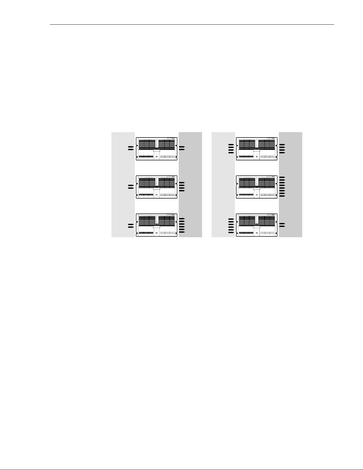
Using the Profile XP Documentation Set
This manual is part of a full set of support documentation for the Profile XP Media
Platform. The following illustrates how to use the Profile XP documentation
depending on the task you are performing.
Path for the Installer
Grass Valley Group
Profile XP
Manual
Family of XP Series
Release Notes
Contains the latest
information about Profile XP
hardware and software
shipped with your system.
Path for the Operator
Grass Valley Group
Profile XP
Manual
Family of XP Series
Release Notes
Contains the latest
information about Profile XP
hardware and software
shipped with your system.
Grass Valley Group
Profile XP
Manual
Family of XP Series
Installation Guide
Contains essential steps for
installing your Profile XP
system using factory
Grass Valley Group
System Guide
Contains the product description
and step-by-step instructions for
modifying system settings.
default settings.
Grass Valley Group
Profile XP
Manual
Family of XP Series
User Manuals
Contains complete instructions for using
Profile applications. These manuals include:
- Profile XP User Manual
- ContentShare Explorer User Manual
- Other user manuals you received with
optional Profile applications.
Profile XP
Manual
Family of XP Series
Installers consult
the User Manuals
as needed.
Grass Valley Group
Profile XP
Manual
Family of XP Series
Grass Valley Group
Profile XP
Manual
Family of XP Series
Other Manuals
These manuals include:
- PFC500 Instruction Manual
- Profile XP Service Manual
with NetCentral.
0624-39
July 27, 200 1 Profile XP System Guide 9
Page 10

Preface
Manual Descriptions
• Installation Guide (for your Profile XP Model) This guide provides step-by-step
instructions for installing the Profile XP Media Platform usi ng fact ory default
settings for all recor d/play channels. Factory default se ttings are indicated within
the guide. After installing the Profile XP system using this installation guide, you
can refer to this Profile XP System Guide to customize system settings for your
installation.
•
Profile XP User Manual Contains complete instructions for using Profile
applications to operate the Profile XP Media Platform.
Profile XP Service Manual with NetCentral Contai n s info rm at ion fo r se rvi ci ng
•
the Profile XP Media Platform and monitoring systems using NetCentral.
Procedures are includ ed for following tasks:
- Setting up and usi ng NetCent ral t o monitor and di agnose problems o n loca l and
remote Profile XP systems.
- Problem analysis using symptom, possible problem, solution table s.
- Running diagnostics
- Replacing field replaceable units.
Profile XP Release Notes Contains the latest information about the Profile
•
hardware and the software release shipped on your system. This information
includes software specifications and requirements, feature changes from the
previous releases, helpful system administrative information, and any known
problems.
• PFC500 Instruction Manual Contains i nformation for servic ing the PFC500 Fibre
Channel RAID Chassis including step-by-step procedures for repl acing f ield
replaceabl e unit s .
10 Profile XP System Guide July 27, 2001
Page 11

How this manual is organized
The Profile XP System Guide is organized around the tasks you’ll be perfo rming to
customize the Profile XP settings to meet your system needs. You can see this
reflected in the chapter titles chosen for this manual. The following identifies and
describes the chapte rs included in this manual:
Chapter 1 - Introducing the Profile XP
Introduces the Profile XP Media Platform. You can read this chapter to get familiar
with the Profile XP key features and system components. Also included is a brief
architectur al overv iew o f the Prof ile X P s ystem.
Chapter 2 - Working with Configuration Manager
Describes the Configur ation Manage r user inter face and functionali ty. Configuration
Manager is the application used to configure and manage the Profile XP system.
Chapter 3 - Working with Profile XP storage systems
Describes how to set up the external storage for the Profile XP. Procedures are
included for conf igurations with mul tiple PFC500 Fibre Chann el RAID Chassis and
PFC500E expansion chassis, and for systems with the optional second controll er
board.
Chapter 4 - Adding or Removing Channels
Describes the basics of adding, configuring, or removing channels. Information on
advanced channel sett ings are referenced to chapters 5 through 7.
Chapter 5 - Modifying a Channel: Video Settings
Describes how to modify the video settings for a channel.
Chapter 6 - Modifying a Channel: Audio Settings
Describes how to modify the audio settings for a channel.
Chapter 7 - Modifying a Channel: Timecode Settings
Describes how to modify the timecode settings for a channel.
Chapter 8 - Controlling the Profile XP Remotely
Describes how to set u p the Profile XP Media Platform for the control mode you want
to use: remote control protocol over RS-422 or remote applications over Ethernet.
July 27, 200 1 Profile XP System Guide 11
Page 12

Preface
Chapter 9 - Setting up a Simple Network
Describes how to set up a simple network of Profile XP systems. Procedures are
included for setting up the Windows NT network and both Profile XP video networ k
options.
Chapter 10 - Solving Common Setup Problems
Provides help for solving common set up problems that occur when Profile XP
features or signal requir ements are not understood.
Appendix A - Electrical and Environmental Specifications
This appendix consists of electrical and environmental specifications.
Appendix B - Connect or Pin-outs
This appendix identif ies connectors and the signals present on the pins of those
connectors.
Appendix C - Rack Mounting Information and Rear Panel Drawings
This appendix provides rack moun ting information for the Profile XP system and
peripheral equipme nt. Also provided are rear panel illustr ations for the Profile XP and
peripheral equipment.
12 Profile XP System Guide July 27, 2001
Page 13

Getting more information
In addition to printed documents, Profile XP product information is available in
on-line manuals and the Profile XP help system. Use these as additional sources for
information.
On-line manuals
Electronic ver sions of the foll owing manuals are located on the system drive of your
Profile XP Media Platform and on the Profil e XP software CD-ROM.
• Installat ion Guide (for your mode l)
• Profile XP System Guide
• Profile XP User Manual
• Profile XP Release Notes
• ContentShare User Guide
• Profile XP Service Manual with NetCen tral XP
You can view these m anuals using Adobe Acrobat Reade r which is al so pre-in stalled
on your Profile XP system.
On-line Help
Contains all the information in the Profile XP System Guide, optimized for use
on-line. You can access on-line help by choosing the Help menu, or by clicking the
Help button in a dialog box.
July 27, 200 1 Profile XP System Guide 13
Page 14

Preface
Grass Valley Group Product Support
You can get technical assistance, c heck on the status of pr oblems, or report new problems by
contacting our Product Sup port Group.
United States and Canada
Monday–Friday 5:30AM–5:00PM Pacific Time
(800) 547-8949
Europe
Monday–Friday 9:00AM–5:30PM
France 01 69 86 83 47 United Ki ngdom 01628 4058 30
Germany 0221 9477 446 Other +44 1628 405840
Italy 02 25086606
Asia and South Amer ica
Australia
- from overseas
Beijing 86-10-62351230
Brazil 55-11-3741-8422 Taiwan 886-2-27571571
Hong Kong 852-25856655
02-9888 0100
61-2-9888 0100
ext. 711
Japan 81-3-3448-3111
Korea 82-2-528-5299
Mexico 52-5-666-6333
Singapore 65-356-3900
World Wide
24-hour Emergency Hotline (530) 478-4148 (Contract and warranty customers)
World Wide Web http://www. grassvalleygroup.com
FTP Site ftp.grassvalleygroup.com
Email ProfileSupport@grassvalleygroup.com
Users Group profile-users@grassvalleygroup.com
14 Profile XP System Guide July 27, 2001
Page 15

Safety Summaries
General Safety Summary
Review the following sa fety precautions to a void injury and prevent damage
to this product or any products conne ct ed to it.
Only qualified personne l should perform service procedures.
While using this product, you may need to acces s other parts of the system.
Read the General Safety summary in other system manuals for warnings and
cautions related to operating the system.
Injury Precautions
Use Proper Power
Cord
Ground the Product This product is grounded through the grounding conductor of the power
Do Not Operate
Without Covers
Do Not operate in
Wet/Damp
Conditions
Do Not Opera te i n an
Explosive
Atmosphere
Avoid Exposed
Circuitry
To avoid fire hazard, use only the power cord spe cified for this product.
cord. To avoid electric shock, the grounding conductor must be connected
to earth gr ound. B efore makin g c onnections to the in put o r output ter minal s
of the product, ensure that the product is properly grounded.
To avoid electric shock or fir e hazar d, do not ope rate this product with
covers or panels removed.
To avoid electric shock, do not operate this product in wet or damp
conditions.
To avoid injury or fire hazard, do not opera te this product in an ex plosive
atmosphere.
To avoid injury, remove jewelry such as rings, watches, and other meta llic
objects. Do not touch exposed conne ctions and componen ts when power is
present.
Product Damage Precautions
Use Proper Power
Source
Provide Proper
Ventilation
Do Not Operate With
Suspec ted Failures
Battery
Replacement
July 27, 200 1 Profile XP System Guide 15
Do not operate this product from a power source tha t applies more t han the
voltage specifie d.
To prevent product overheating, provide proper ventilation.
If you suspect there is dama ge to this product, have it inspected by qualifi ed
service personnel.
To avoid damage, replace only with the same or equiva lent type
recommended by the circuit board manufacturer. Dispose of used battery
according to the circuit board manufacturer’s instructions.
Page 16

Safety Summaries
Safety Terms and Symbols
Terms in This
Manual
!
!
Terms on the
Product
Symbols on the
Product
These terms may appear in this manual:
WARNING: Warning st atements identi fy conditions or practi ces that can
result in personal injur y or loss of life.
CAUTION: Caution statements identify conditions or practices that can
result in damage to the equipment or other property.
These terms may appear on the product:
DANGER indicates a person al inj ury ha zard i mmediately acc essible as one
reads the marking.
WARNING indicates a personal injury hazard not immediately accessible
as you read the marking.
CAUTION indicates a hazard to property inc luding the product.
The following symbols may appear on the produc t:
DANGER high voltage
Protective ground (ear th) terminal
!
ATTENTION – refer to manual
Service Safety Summary
Do Not Service
Alone
Disconnect Power To avoid elect ri c shock, disconnect the main power by means of the power
Use Care When
Servicing With
Power On
Do not perform interna l service or adjus tment of this pr oduct unless another
person capable of rendering first aid and resuscitation is present.
cord or, if provided, the power switch.
Dangerous voltages or currents may exi st in this produc t. Disconnect power
and remove battery (if applicable) before removing protective panels,
soldering, or replacing components.
To avoid electric shock, do not touch exposed connections
16 Profile XP System Guide July 27, 2001
Page 17

Certifications and Compliances
Safety Summaries
Canadian Certified
Power Cords
FCC Emission
Control
Canadian EMC
Notice of
Compliance
Canadian approval incl udes the products and power cords appropriate for
use in the North Ameri ca power network. All other power cords supplied are
approved for the country of use.
This equipment has been tested and found to comply with the limits for a
Class A digital device, pursuant to Part 15 of the FCC Rules. These limits
are designed to provide reasonable protection against harmf ul interference
when the equipment is operated in a commercial environment. This
equipment generates, uses, and can radiate radio frequency energy and, if
not installed and used in accordance with the instruction manual, may cause
harmful inter ference t o rad io communic ations . Opera tion of thi s equipmen t
in a reside ntial area is like ly to cause harmful int erfere nce in whic h case the
user will be r equired t o correct t he interfer ence at his own expense . Changes
or modifications not expressly approved by Tektronix can affect emission
compliance and could void the user’s authority to operate this equipment.
This digital apparatus does not exceed the Class A limits for radio noise
emissions from digital apparatus set out in the Radio Interference
Regulations of the Canadian Department of Communications.
Le présent appareil num érique n’émet pas de bruit s radioélectriques
dépassant les limites applicables aux appareils numériques de la classe A
préscrites dans le Règlement sur le brouillage radioélectrique édicté par le
ministère des Communications du Canada.
Canadian Certified
AC Adapter
EN55022 Class A
Warning
Laser C om p liance
Laser Safety
Requirements
Canadian approval incl udes the AC adapters appropriate for use in the
North America power network. All other AC adapters supplied are
approved for the country of use.
For products that comply with Class A. In a domestic environment this
product may cause radio interf erence in which case the user may be
required to take adequate measures.
The device used in thi s product is a Class 1 cer tified laser product . Operating
this product out side specifications or altering its origina l design may result
in hazardous radiation exposure, and may be con sidered an act of modif ying
or new manufactur ing of a laser product under U. S. regulat ions contained in
21CFR Chapter 1, subchapter J or CENELEC regulations in HD 482 S1.
People performing such an act are req uired by law to recertify and reidenti fy
this product in accordanc e with provisions of 21CFR subchapter J for
distribution within the U.S.A., and in accordance with CENELEC HD 482
S1 for distribution wit hin countries using the IEC 825 standard.
July 27, 200 1 Profile XP System Guide 17
Page 18

Safety Summaries
Laser Safety Laser safety in the United States is regulated by the Center for Devi ces and
Radiological Hea lth (CDRH). The laser safety regulations are published in
the “Laser Product Performance Standard,” Code of Federal Regulation
(CFR), Title 21, Subchapter J.
The International Electrotechnical Commission (IEC) Standard 825,
“Radiation of Laser Produc ts, Equi pment Clas sific ation, Requirements a nd
User’s Guide,” governs laser products outside th e United States. Europe and
member nations of the European Free Trade Association fall under the
jurisdiction of the Comité Européen de Normalization Electrotechnique
(CENELEC).
FCC Emission
Limits
Certification
Category Standard
Safety Designe d/tested for com pliance with:
This device c omplies with Part 1 5 of the FCC R ules. Operati on i s subje ct t o
the following two conditions: (1) This device may not cause harmful
interferen ce, and (2) thi s devi ce mu st acc ep t any int erf erence received ,
including interf erence that may cause undesirable operation.
UL1950 - Sa fe ty of Inf or mation Techn olo gy Equipme nt, incl udi ng Elect ri cal Bus in ess
Equipment (Third Edition, 1995)
IEC 950 - Sa fe ty o f Info rma tion Te chn ol ogy Equi pment , inclu di ng Elec tric al Busines s
Equipment (Second editi on, 1991)
CAN/CSA C22.2, No. 950-95 - Safety of Information Technology Equi pm ent,
including Electrical Business Equip m ent
EN60950 - Sa fety of Inf ormation Technol ogy Eq uipment, includi ng El ectric al Busin ess
Equipment
18 Profile XP System Guide July 27, 2001
Page 19

Chapter
1
Introducing the Profile XP
The Profile XP Media Platform provide s a multi- channel, high bandwidth platform
for the storage and manipul ation of video and a udio i n profess ional applic ation s. The
Profile XP has a wide range of capabilit ies, from a stand alone digita l disk recorder to
being part of a large ne twork of video s ervers. The Prof ile XP Media Plat form can be
used in a wide variety of applications including spot insertion, program delay, store
and forward, and multi-channe l replay.
Profile XP Media Platform highlights
Highlights include:
• Up to 8 channels of broadcast-qual ity video
• MPEG-2 4:2:2 @ Main Level from 4-50Mb/s, long GOP
• SMPTE 259M, 270MHz Serial Digital I/O (Analog monitor optional)
• 16/32 channels audio — AES/EBU, embedded, analog uncompressed audio,
Dolby E and AC-3 compressed audio
• 600Mb/s System Bandwidth
• Redundant power supply, NT disk, cooling fans for reliability
• Fibre Channel attached high performance RAID storage
• Remote error reporting & monitor ing via SNMP
• High speed Fibre Channel networking up to 300Mb/s
• 100BaseT Ethernet networking up to 30Mb/s
• 525/60 or 625/50 operation: accepts NTSC, PAL reference.
• Remote control including:
- Remote Applications over Ethernet
- RS-422 control protocol including Louth, Odetics, BVW, or Profile protocols.
- GPI Trigger (8 I/O)
July 27, 200 1 Profile XP System Guide 19
Page 20
Chapter 1 Introducing the Profile XP
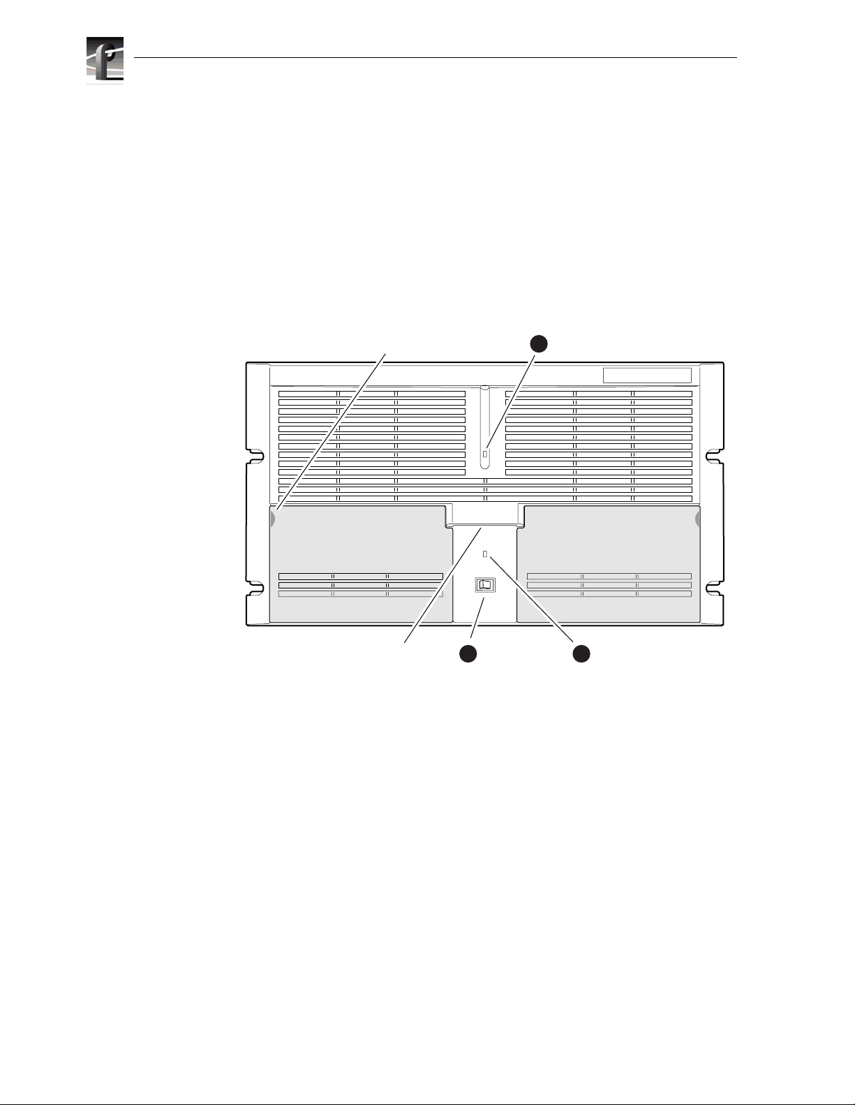
Front panel controls and indicators
The Profile XP front panel include s the following controls and indicators :
➊ Power-On LED - indicates the standby switch is in the on position and that
secondary voltages are present in the chassis.
➋ Standby Switch - provides syste m On/Off control.
➌ System Fault LED - indicates a syst em fault exist somewhere in the Profile XP
unit.
Pull here to
open (each side)
Accessory
Door
Standby/On
2
Switch
1
Standby/On LED
Accessory
Door
System
3Chassis Pull
Fault LED
0624-5
20 Profile XP System Guide July 27, 2001
Page 21
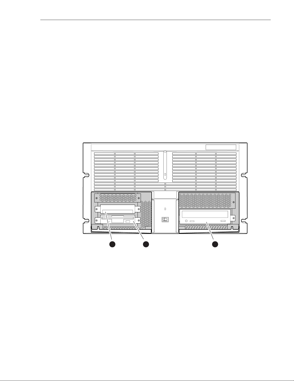
Front panel controls and indicators
The Profile XP fr ont panel fea tures two ac cessory doors tha t provide a ccess to se veral
storage devices. The follo wing describes the stor age devices install ed on the standard
Profile XP system.
➊ System Disk - conta ins the Windows NT operatin g syst em and Profil e XP system
software and applications.
➋ 1.44MB Floppy Disk Drive
➌ CD-ROM Drive - for maintaining the Windows NT operating system and
performing Profil e XP system software upgrades.
NOTE: If an accessory door is accidental ly dislocated from its hinges, you can
easily pop it back into place.
0624-4
System
1
Disk Drive
July 27, 200 1 Profile XP System Guide 21
Floppy
2
Disk Drive
CD-ROM
3
Drive
Page 22
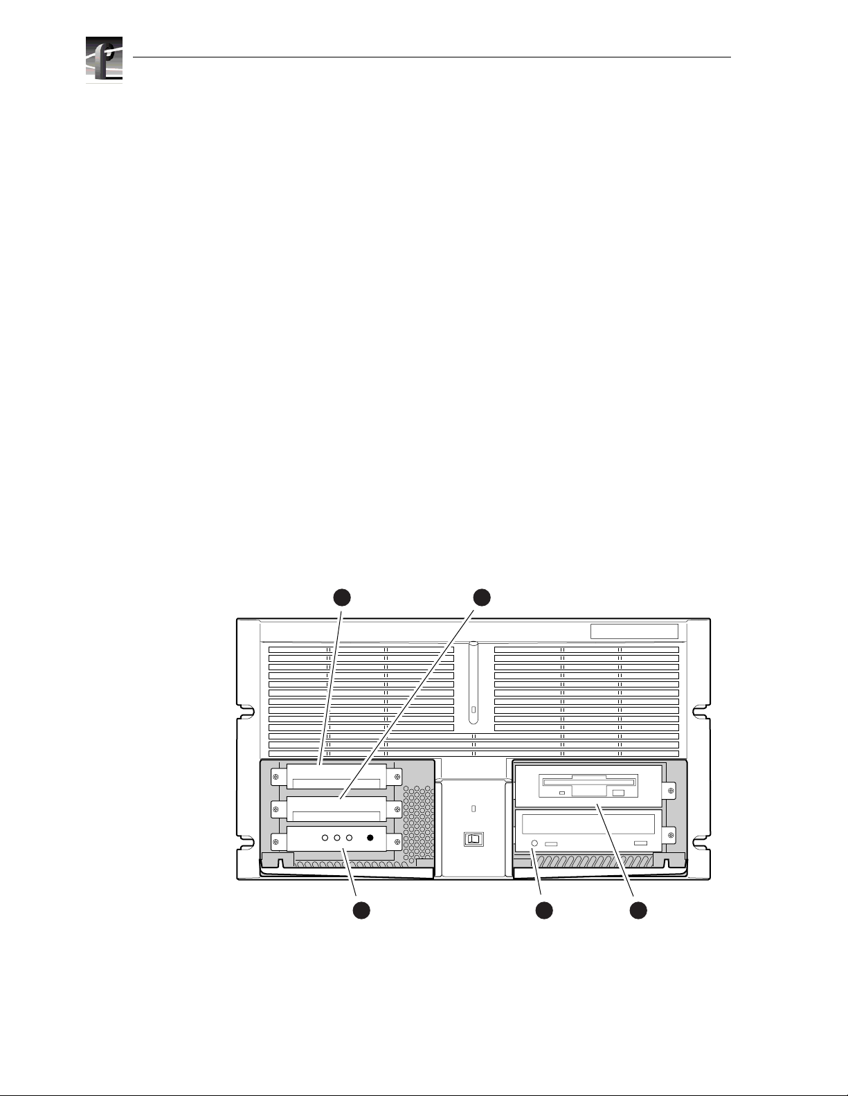
Chapter 1 Introducing the Profile XP
The following describe s the storage devices in a Profile XP system with the redundant
system disk option.
➊ Primary System Drive - contains Windows NT operatin g system and Profile XP
software and applications.
➋ Mirror Syst em Disk - mirrors primary s ystem disk and provides autom atic fail-over
in the event the pr imary system d isk fails.
➌ Drive Mirroring Controller and Indicator Panel -
The Indicator Panel status LEDs indicate the operating mode of the mirroring
system as follows:
- Green - Drives are in Mirror mode
- Red - Drives in Single mode
- Orange - Drive activity
The Buzzer Off switch can be used to silence the buzzer, which sounds under the
following conditi ons:
- Short beep during power on indicates successful boot-up
- Second beep indicates the mirror ing system is running in single mode
- Continuous or intermittent beep indicates a drive failure
➍ CD-ROM Drive - for maintaining the Windows NT operating system and
performing Profil e XP system software upgrades.
➎ 120MB Super-Drive - accepts 1.44MB floppy disks and 120MB disks.
Dupli
Disk
Primary System
1
Disk Drive
Primary
Mirror Status Buzzer
3
DupliDisk
Indicator Panel
Mirrored System
2
Disk Drive
4
CD-ROM
Drive
5
0625-18
Superdrive
22 Profile XP System Guide July 27, 2001
Page 23
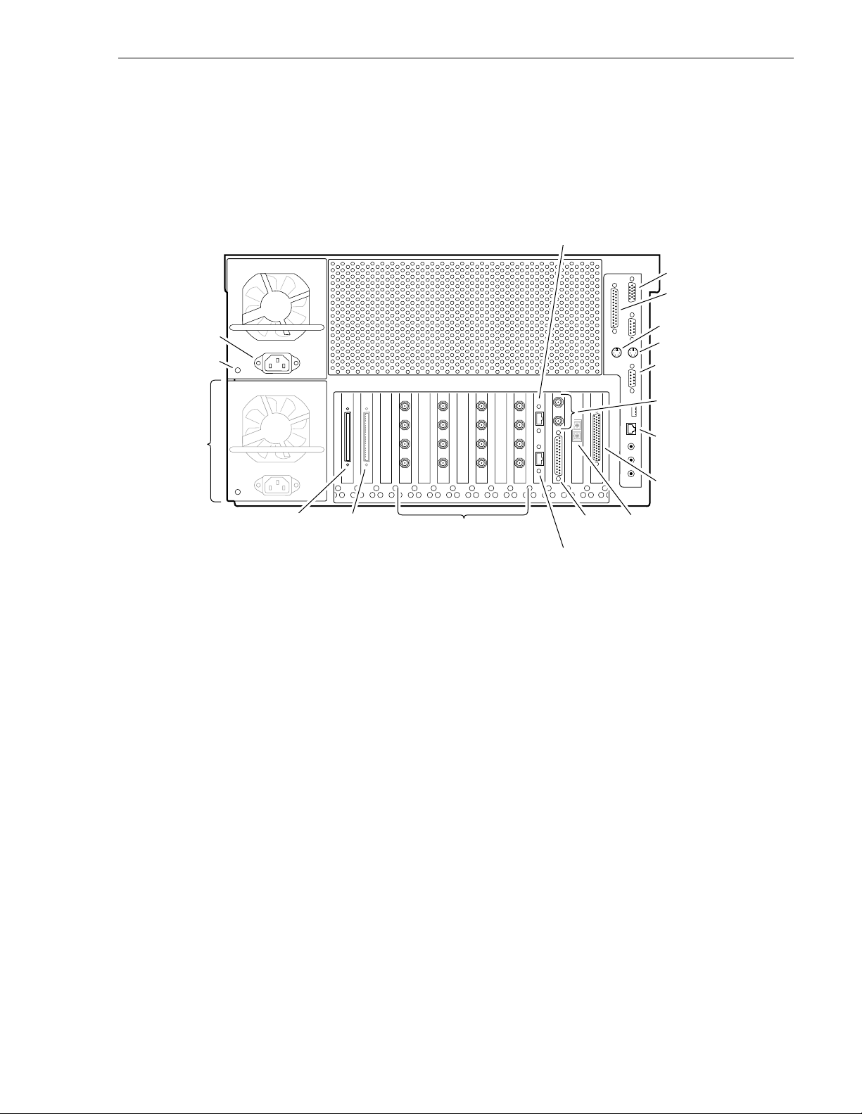
Rear Panel View
The figure shows the Profile XP rear panel connectors. Rear panel drawings for
peripheral equipment are located in Appendix C, “Rack Mounting Information and
Rear Panel Drawings”.
Rear Panel View
Power Cord
Power
Good LED
Optional
Power
Supply
PVS 1000 Media Platform
Audio
Channels
1-16
Audio
Channels
1-16 (opt.)
FC Disk (Port A)
Video Monitor, Video I/O,
or Video Out
FC Disk (Port B)
LTC/
GPI
Monitor
Parallel Port
Mouse
Keyboard
Com1 (RS-232)
Reference In
(Loop-Thru)
Ethernet
(Windows NT
Network)
RS-422
Breakout
Video
network (opt.)
0624-1
July 27, 200 1 Profile XP System Guide 23
Page 24

Chapter 1 Introducing the Profile XP
Standard accessories shipped with the Profile XP
The Profile XP Media Platform is shipped with the fol lowing standard accessories :
• Manuals Include:
- Installation Guide
- Profile XP System Guide
- Profile XP User Manual
- Profile XP Service Manual with NetCentral
- Content Share User Manual
- Profile XP Release Notes
• Software package which includes the Profile XP Software CD-ROM and an
emergency repair disk.
• Windows NT software package
• Keyboard and mouse
• I/O Panel and cables (provides LTC, RS-422 & GPI interfaces)
• Power cabl e assemb ly
• Rack mounting slides
• Ethernet cable
24 Profile XP System Guide July 27, 2001
Page 25
Profile XP Media Platform features
Profile XP Media Platform features
The Profile XP Media Plat form is an a ll digi tal a rch itectur e suppor ting S DI vide o I/ O
and either uncompressed or compressed audio.
Summary of Prof ile XP Mo de ls
Profile XP is available in several factory installed configurations. The following
figure shows the number of encoders and decoders available in each model.
Number of
Encoders
PVS1022 PVS1044
22
PVS1024 PVS1008
2
PVS1026 PVS1062
2
Number of
Decoders
4
6
Number of
Encoders
44
0
6
About channels and factory default configuration
Profile applications use channels to control disk recording and playback. A channel
defines a grouping of Profile XP video, audio, and timecode resources and is
identified by a unique name. Profile XP software supports three channel types:
Recorder channel, Player channel, or Player/Recorder channel. For more information
on channel types and creating or modifying channels, refer the Profile XP System
Guide.
Number of
Decoders
8
2
0624-19
Your Profile XP system is shipped with def ault Rec order and Playe r channels. These
default channe ls are named Vtr 1, Vtr2, Vt r3 and so on. The follo wing table desc ribes
the video and audio connections you’ll make for the two channel types. The
July 27, 200 1 Profile XP System Guide 25
Page 26

Chapter 1 Introducing the Profile XP
Installation Guide contains specifics about the type and number of default channels
in your Profile XP model, and their video and audio I/O connections.
Default
channel
type
Recorder 1 SDI video input
Player 1 SDI video output 2, 4, or 8 audio I/Os Recorded timecode is
a.
The number of audio I/Os is determined by your Profile XP model and the numbe r of Audio
boards in stalled.
b.
Availab le if the optional Video Monitor board is installed.
Video I/O
connections
1 analog moni tor
You can use the information in this System Guide to modify default channel setting s
to satisfy the needs of your syste m. For more infor mation about channels, refer to
Chapter 4, Adding or Removing Channels.
Video compression
The Profile XP Media Platform uses MPEG 2 4:2:2 @ Main Level encoding with
selectable bit r ates f rom 4Mbs to 50M bs. The addi tional c hroma res oluti on that 4: 2:2
sampling gives provides good mult i-generation capability as well as up-conversion
quality.
Seamless play and cuts editing at any bit rate and any GOP is made possible by the
Profile XP dual MPEG decoder arc hitec ture tha t allows stora ge effic ienci es of a l ong
GOP and maintains the ability to cut on any frame and play clips back-to-back
seamlessly. This provides all of the advantages of long GOP encoding, without the
limitations.
Audio connections
b
2, 4, or 8 audio I/Os Uses the internal
a
Timecode I/O
timecode ge nerator.
used to generat e VITC on
the SDI video output
26 Profile XP System Guide July 27, 2001
Page 27

Fibre Channel RAID storage
Profile XP storage is comprised of the PFC500 Fibre Channel RAID Chassis and the
PFC500E Expansion Chassis. Both are 3.5 RU ten drive Fibre Channel disk arrays
with hot swap and redunda nt drives, p ower suppli es and fa ns. The PFC500 houses the
controller for the system.
The PFC500 Fibre Channel RAID Chassis contains five or ten 18 or 36 GB drives.
Additional storage is available by adding up to two PFC500E Expansion Chassis.
Each PFC500E Expansion chassis can hold five or ten 18 (PFC518) or 36 GB
(PFC536) drives. The PFC500’s RAID controll er will control up to two PFC500E
expansion chassis.
The PFC500 is available in a two controller configuration for redundancy. I f the
primary RAID Controller fai ls, the system will automatically swit ch over to the
redundant controlle r within a few seconds.
The PFC500 is configured to use RAID-3 storage for hig h availability to media.
Fibre Channel and/or Ethernet IP Networks
The Profile XP family offers tru e IP networking over Fibre Channel or Ethernet.
• Faster than real time tran sfer s (up to 40x) with no generation loss
Fibre Channel RAID storage
• Reliable tran sfers using secure file tra n sfer pr o toc ols
• IP networking enables file s to be m oved between de vices or between facilit ies over
standard public networ ks.
• Profile network stre aming enables “play while t rans fer ri ng”
Fibre Channel Streaming enables the file to be used shortly after the destination
Profile starts receiving it — just like you can do with a traditional video router. This
eliminates the traditional drawback of networking in which the file must finish
transferri ng befo re a user h as acces s to edit it or play it out .
July 27, 200 1 Profile XP System Guide 27
Page 28
Chapter 1 Introducing the Profile XP
Profile XP Media Platform system overview
The Profile XP Media Platform system is an extension to a standard PCI bus-based
Windows NT computer. This standard is enhanced to add functionality and
performance necessary to deliver an industrial grade, broadcast quality disk based
video server. Thi s sect ion discu sses the major archi tectu ral bl ocks, what t hey do, and
how they interconnect.
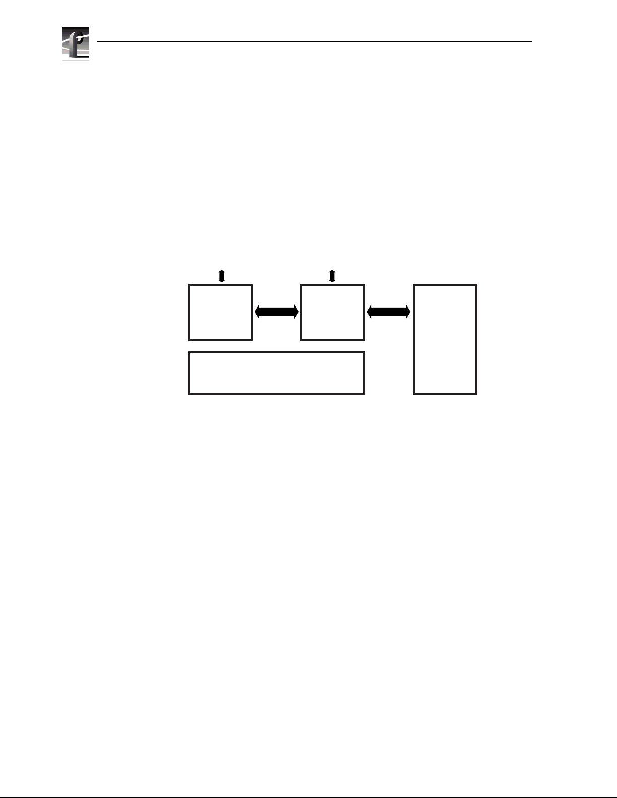
High level block diagram
The Profile XP Media Platform has three subsystems: Application Subsystem, Real
Time Subsystem, and Storage Subsystem.
User Interface, Control,
Configuration
Application
Subsystem
Application Subsystem
The Application Subsyst em is a Windows NT computer subsystem. The Application
Subsystem provides a platform for running Windows based applications for
configuring and contr olling the Real Time Subsystem both locally and remotely.
Real Time Subsystem
The Real-Time Subsys tem contains a real tim e proc essor and peripheral devices and
runs the VXWorks operating system.The Real Time Subsystem manages all the
hardware involved in contr olling the flow of video, audio, tim ecode in and out of the
system. This inc ludes vid eo I/O boards , audio I/O boards , vide o compression boards,
and networking and s torage. The Real Time Subsystem is controlled by appl ications
running on the Applications Subsystem using Inter-Processor Messaging channels
(IPM). It is responsible for the execution of events on the play timeline.
IPM
Channel
Platform
Resources
Video I/O, Audio I/O,
Media Networking
Real Time
Subsystem
Fibre
Channel
Media
Storage
Subsystem
0624-40
Media Storage Subsystem
The Storage Subsystem is where the video, audio, timecode and other media related
data is stored. This storage system is made up of one or more external RAID level 3
storage chassis containing Fibr e Channel disks. The Profile XP Real Time Subsy stem
controls read/write disk operations by sending SCSI protocol commands ove r one or
more Fibre Channel links.
28 Profile XP System Guide July 27, 2001
Page 29

Platform R esources
The platform resources provide the infrastructure necessary to operate, interconnect,
and integra te all the Application Subs ystem, Real Ti me Subsystem components. The
elements that comprise the Platform Resources are: Multi-sl ot PCI bus, video & audio
crosspoint fabric , powe r supply and system cooling.
High level block diagram
July 27, 200 1 Profile XP System Guide 29
Page 30
Chapter 1 Introducing the Profile XP
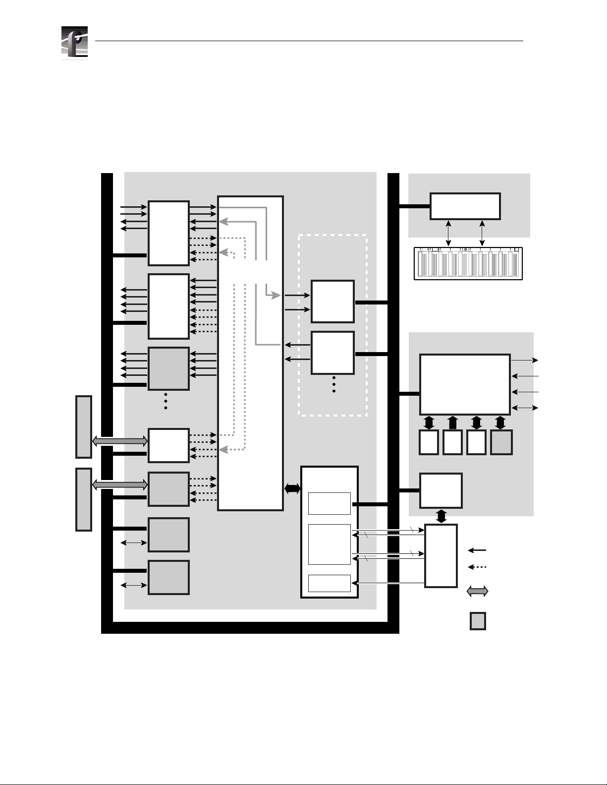
Board level block diagram
This section describes the Profile XP architecture in more detail using a board level
block diagram. From this discussion you‘l l gain an understanding of the basic signal
flow in the Profile XP system. Use this information when you are installing and
setting up the Profile XP Media Platform.
PCI Bus
Audio Interface Audio Interface
Net.
Net.
SDI
2In/2Out
SDI
4Out
Video
Monitor
NTSC/PAL
Add. I/O Boards
Audio
(Ch1-16)
Audio
(Ch1-16)
Ethernet
Video
Network
Fibre Ch.
Video
Network
Real Time Subsystem
Crosspoint
Examples
Video/Audio
Crosspoint
Fabric
PCI Bus
Video
Compression
(up to 8 channels
total)
MPEG-2
Encoder
(2Ch SD)
MPEG-2
Decoder
(2Ch SD)
Add. Encoder/
Decoder Boards
Real Time
System Board
Real Time
Processor
LTC & GPI
I/Os
Genlock
LTC
4
GPI
8
Ref In
Media Storage Subsystem
Fibre Channel
Disk Interface
Port A Port B
024
6810
#
#
0 1 2 3 4 5 6 7 8 9
135
7911
PFC 500 System
(RAID 3 Storage)
Applications Subsystem
PCI Bus
Applications
Processor
(plus Windows NT)
3.5FDCD HD Mirror
8 CH
RS-422
Interface
4
I/O
8
Panel
0624-38
SVGA
Mouse
Kybd
Ethernet
HD
Video
Embedded
Audio
AES/EBU
Audio
Profile XP
Optional item
30 Profile XP System Guide July 27, 2001
Page 31

Motherboard
The Profile XP system motherboard con tains 14 board slots. Each slot includes a
connection to the system PCI bus and the Video/Audio Transport Fabric. The video/
Audio transport fabric is an integrated 96x96 crosspoint switch which provides
uncompressed video (CCIR601) and audio (24bit) routing. Video is routed in
Applications Subsystem
The Applications Subsyst em is a Windows NT computer system and includes the
following components :
Application Processor Board
The Application Engine is a standar d NLX single board computer. The Application
Subsystem provides a platform for running Windows based applications for
configuring a nd controllin g the Real Time Subsyst em both l ocally and remotely. Rear
panel I/O includes:
• Mouse, Keyboard, and SVGA Connectors
• Two Serial Ports
• One Parallel Port
Board level block diagram
• Two USB Ports
• Audio Line Level IN/OUT, and Mic Input
• 10/100BASE-T RJ-45 Ethernet Port
RS422 Board
This RS-422 adapter is instal led as part of the Applications Processor system under
Windows NT. Control applications running on the Application Processor receive
control commands from a remote protocol listener that monitors the RS-422 ports.
Real Time Subsystem
The Real Time Subsystem includes the following components:
Real Time Processor
The Real Time Proce ssor boar d conta ins a real t ime proc essor and peri pheral de vices
and runs the VXWorks operating system.This board manages all the hardware
involved in controlling the flow of video, audio, timecode in and out of the system.
This includes video I/O boards, audio I/O boards, video compression boards, and
networking and storage . Othe r board functionality includes:
• Generation of system 27MHz clock and fr ame reference pulse locked to refe rence
video input.
• LTC In reader and LTC Out generator.
• VITC reader for reference video input.
• GPIO (8 In, 8 Out)
• Black generator and Colorba r generator used for loss of input or output video
conditions.
July 27, 200 1 Profile XP System Guide 31
Page 32

Chapter 1 Introducing the Profile XP
Serial Digital Video Boards
These boards provide four ser ial digital video (270Mb/s SMPTE 259M), either
2In/2Out or 4 Out, t hrough f our B NC connector s on the rear of the board. An inte rna l
frame buffer is provided for each video input on the board for auto-timing
synchronous and a synchronous in puts. Embedded a udio is supp ort ed —maxi m um of
8 channels a udio per vide o input— and is routed over the video routing f abric. VITC
can be read from each input and generated on each output.
Video Monitor (Optional)
The Video Monitor board provides 4 a nalog composite vide o outputs for monit oring
purposes. The outputs include Text Overlay and Timecode burnin.
Audio Board
The Audio board provides sixteen ch annels of 16 or 24 bit audio I/O. An additional
Audio Board may be added as an option for a total of 32 channels of audio.
Audio I/O formats include
• Embedded
• AES/EBU
• Analog
The Audio board incl udes a rear panel 80 pi n interface connector for AES/EBU audio
I/O. For AES/EBU operatio n, a breakout pa nel is re quired. F or op eration with analog
signals, the PAC216 Analog Audio Chassis is required for conversion of analog
signals to AES/EBU.
Embedded audio is extracted from the video inputs by the Video I/O boards and
routed over the Video/Audio Transport Fabric to the Audio board.
Audio processe d by the Audio board is rout ed over the PCI bus to th e Media Storage
Subsystem. The audio board does not compress the audio for storage, but can pass
through pre-compressed Dolby E and AC-3 compressed signals.
MPEG-2 Encoder and Decoder Boards
Each MPEG-2 Encoder or MPEG-2 Decoder board provides 2 channels of video
processing. Encoding bit rates are from 4Mb/s to 50 Mb/s. Up to four of these type
boards can be installed in a Profile XP system.
For record mode, video is route d from the Vid eo I/O boards, over the video tra nsport
fabric to the MPEG-2 Encoder Board. MPEG-2 compressed da ta is moved over the
PCI bus to the Media Sto rage Subsystem. For play mode, MPEG- 2 compressed data
is routed fr om the Media Storage Subsystem, over PCI bus, to the MPEG-2 Decoder
board where the d ata is processed. Full bandwidth video is r outed from the MPEG-2
Decoder board over the video tran spor t fabric to the Video I/O boards.
Video Network Adapter (Optional)
The Video Network Adapter is a 1Gb/s Fibre Channel board or 100BaseT Ethe rnet
board for video network connections. Both provide faster than real-time transfers of
video data.
32 Profile XP System Guide July 27, 2001
Page 33

Media Storage Subsystem
The Media Storage Subsystem includ es the following components:
Fibre Channel Disk Board
This is a dua l port Fibre Channel Disk boar d f or connecting the Profile XP system to
the external Fibre Channel RAID storage system. Both ports use a copper Gigabit
Link Module (GLM) for co pper Fibre Channel c ables. The syste m normally ope rates
with only Port A connecte d to the PFC500 system. When the PFC500 is ordered with
the optional second contr oller boa rd, Port B can be connecte d to provide a redundant
path to the disks, or for increased disk I/O bandwidth.
PFC500 Fibre Channel RAID Chassis
The PFC500 high performance RAID storage system provides the Profile XP a low
profile, compact storage syste m with either 18 GB or 36 GB fibr e channel drives. The
PFC500 is a 3.5 RU 10 drive Fibre Channel disk array with RAID drives, hot spares,
dual power supplies (optiona l), redundant controller s (optional) and spare fans – all
hot swappable.
The PFC500 comes with either 18 GB (PFC518) or 36 GB drives (PFC536).
Expansion can be done wi th t he PFC518E/536E exp ansion sy stem whi ch houses 5 or
10 drives but does not need a RAID controller. The PFC500’s RAID controller will
control up to 2 expansion frames (30 total drives). The PFC500 offers optional
redundant RAID controlle rs. If one fails, the system will automatic ally switch over to
the second controlle r within a few seconds.
Board level block diagram
July 27, 200 1 Profile XP System Guide 33
Page 34

Chapter 1 Introducing the Profile XP
Starting the Profile XP system
When starting your system, you must power-on the Profile XP Media Platform and
the PFC500 storage system as described in the following procedure.
To power-on the Profile XP system:
1. Turn on power to all peripheral devices connected to the Profile XP. The PFC500
and PFC 500E power switches are located behind the fan pack as shown.
Power Cord (115V/230V)
l
0
ON
OFF
Optional Power Supply
2. After about 90 seconds, verify that the
OFF
0
l
Power Cord (115V/230V)
System Check LED is out on the PFC500
P/S
ON
A
B
Fibre Channel RAID Chassis and all PFC500E Expansion Chassis, if installed.
Refer to the PFC500 Instruction Manual for more information if the System Check
LED remains lit.
System Check LED
Power LED
PFC500 and PFC500E
024
6810
#
135
7911
#
0 1 2 3 4 5 6 7 8 9
System Check LED
turns off approximate ly
90 secs after power-up.
0624-24
NOTE: Do not power-on the PVS1000 until the PFC500 Fibre Channel RAID
storage system is fully initialized; approximately 2-3 minutes.
3. Turn on the power to the Profile XP Media Platform and wait for Windows NT to
initialize and per form auto-logon. The Windows NT desktop will appear after
successful auto- logon.
34 Profile XP System Guide July 27, 2001
Page 35

Logging on Windows NT
When the Profile system powe red-on and befor e Windows NT boots , you mus t make
a choice of how you want to logon the system.
Automatic Logon
When the Profile XP system is powered on, you may let Windows NT go through an
automatic logon sequence . The syste m will perform automatic logon using a default
account call ed profile. After automatic logon, the Windows NT desktop will appear.
Automatic logon will occur at power On when:
-The profile account was used the last time the Profile XP Media Platform was
turned off.
- The Profile XP Media Platform is initially powered On from the factory. (The
factory sets the last use r to profile prior to shipment.)
Logging on as Administrator
When the Profile XP system is powered On, you may interrupt automatic logon and
logon as Administrator. It is not necessary to logon as administrator to configure
Profile System sof tware. However, you must log on as Administrator for Windows NT
administration and to:
Logging on Windows NT
- Configure Ethernet network settings (see Chapter 9, Setting up a Simple
Network).
- Install new software applications or upgrades (see Profil e XP Release Notes).
To log on as Administrator at Power Up
To logon as Administrator at power-up:
1. Power-on the Profile XP system, then hold the
prevent auto-logon as profile. Be sure to continue holding the shift key until the
logon dialog box appears.
2. Logon as administrator. The default administrator password o n a Profile syst em is
triton.
The next time the Profile XP system is restarted, Windows NT will display a logon
error message. When this occurs, use the logon dialog box to logon manually as
administrator or as profile (see the followi ng pro ced ure).
Shift key down during start-up to
July 27, 200 1 Profile XP System Guide 35
Page 36

Chapter 1 Introducing the Profile XP
Logging on as Administrator from Profile account
To logon as Administrator from Profile account:
1. Log on as Administrator using the following steps:
a. Press the
Control-Alt-Del key seq uence . The Windows NT Security dialog box
appears.
b. Click
Log off. The Log off Windows NT dialog box appears.
c. Press and hold down the
NOTE: You mu s t hol d down the shift key to over-ri d e aut o -logo n .
d. When the Begin Logon dialog box appears release the
Control-Alt-Del key sequenc e.
e. Enter the following, then click
Username: Administrator
Password: triton
You are now logged on as Administrator and can modify system settings.
Logging on as Profi le
After performing syst em administrative tasks using the Administrator user account,
Profile account to enable the automatic logon feature for future system boots.
To logon as profile:
1. Power up or log off the Profile XP System.
Shift key on the Profile XP keyboard, then click OK.
Shift key, then press the
OK.
2. When the logon error message appears click
3. Enter the following, then click
OK.
OK.
Username: Profile
Password: profile
Windows NT will now perform automatic logon the next tim e the system is
restarted.
36 Profile XP System Guide July 27, 2001
Page 37

Shutting down the Profile XP system
Shutting down the Profile XP system
To shutdown your Profile XP system without loss of data, you must:
1. Quit all Profile applications by selecting
Quit or Exit from the File menu.
2. Exit or Quit any other processes which may be running in the same way.
3. Shutdown Windows NT by pressing the
choosing
Shutdown.
CTRL+ALT+DEL key sequence and
4. When Windows NT displays a message that it is safe to turn off the system, turn
the front panel switch to
Standby.
5. Power-off all periphe ral de vices including the PFC500 Fibre Channel RAID
chassis and PFC500E Expansion chassis (if installed) as shown.
Power Cord (115V/230V)
l
0
ON
OFF
Optional Power Supply
OFF
ON
0
l
Power Cord (115V/230V)
P/S
A
B
July 27, 200 1 Profile XP System Guide 37
Page 38

Chapter 1 Introducing the Profile XP
38 Profile XP System Guide July 27, 2001
Page 39

Chapter
2
Working with Configuration Manager
Configuration manage r is the tool you’ll use to set up the Profile XP for operation.
You’ll use Configuration Manager to do things like create a video file system on the
RAID storage system, create or modify channels, and configure system hardware
settings. The Configuration Manager window appears as shown.
This chapter gives a brief tour of Configuration Manager. Also included are
instructions for remote configuration and saving/restoring configuration set tings.
Sections in this chapte r include:
• Tour of Configuration Manager
• Viewing board location information
• Saving and restoring your syste m settings
• Importing and Exporting syste m settings
• Remote configuration: NetCentral XP Enterprise
July 27, 200 1 Profile XP System Guide 39
Page 40

Chapter 2 Working with Configuration Manager
Tour of Configuration Manager
Configuration Manager pr ovides a central graphical user interfa ce for all system
configuration tasks. Configuration Manager includes the following selection items:
• File System - used to configure the media storage system
• Network - used to set up the video network option
• Video setup items - used to configure video input and output settings
• Audio setup items - used to configure audio input and output settings
• Channel Configuration - used to add and modify channels.
File System
Choosing File System in Configuration Manager opens the Disk Utility dialog box.
Use the pages in the Disk Utility to configure storage for the Profile XP system.
For more information on configuring s torage, se e Chapter 3, Wor king with Profile XP
storage systems.
40 Profile XP System Guide July 27, 2001
Page 41

Network
Network
Choosing Network in C onfigura tio n Manager op ens the video n etwork con figur ation
pages. Use these pages to configure the settings for the optional video network.
For more information on setting up the video network option, see Chapter 9, Setting
up a Simple Network.
July 27, 200 1 Profile XP System Guide 41
Page 42

Chapter 2 Working with Configuration Manager
Video setup items
Configuration Manager inc ludes four items used for configuring the video
input/output settings. These include:
• Video Timing - used to select the video stan dard and for setting up reference
genlock and video output timing.
• Video Input - used to configure the set tings for each video input, including:
input frame buffer ope ration, input blanking, loss of signal behavior and VITC
reader settings.
• Video Output - used to configure the settings for each video output including:
loss of signal behavior, vertical interval bla nking, and VITC generator settings.
• Video Monitor - used to set up timecod e burn-in and t ext over lay on the opti onal
video monitor board.
See Chapter 5, Modifying a Channel: Video Settings, for more info rmatio n on
modifying video setti ngs.
42 Profile XP System Guide July 27, 2001
Page 43

Audio setup items
Configuration Manager inc ludes four menu items used for configuring the audio
input/output settings. These include:
• Audio Reference - used to set the audio reference level. The audio reference
level is used to set the default audio level in some Profile applications.
• Audio Input - used to adjust the analog audio input gain and monitor the status
of AES/EBU input signals.
• Audio Output - used to adjust the analog audio output gain.
• Audio Routing - used to set up audio sources and destinations for Profile XP
audio channels.
See Chapter 6, Modifying a Channel: Audio Settings, for more information on
modifying audio setti ngs.
Audio setup items
July 27, 200 1 Profile XP System Guide 43
Page 44

Chapter 2 Working with Configuration Manager
Channel Configuration
Choosing Channel Configuration in Configuration Manager opens the Channel
Configuration window. Channel Configuration is used to modify or create channels
that are used by Pr ofile ap p lic at ions .
See Chapter 4, Adding or Removing Channe ls, for more information on using Channel
Configuration.
44 Profile XP System Guide July 27, 2001
Page 45

Viewing hardware settings summary dialog boxes
Viewing hardware settings summary dialog boxes
Use summary dialog boxes to view hardware set tings in Configuration Manager.
Summary dialog boxes are displaye d when you click the Finish button on a
configuration page. The Video Monitor Summary dialog box is shown here as an
example.
Clicking
saving your settings. Clicking the
Back in a summary di alog box r eturns y ou t o the con figurat ion page without
OK closes the summary dia log box and saves your
settings.
July 27, 200 1 Profile XP System Guide 45
Page 46

Chapter 2 Working with Configuration Manager
Show or hide summary dialog boxes
You can choose to h ide the summary dia log boxes. Thi s allows you to c lick the Fini sh
button on confi guration pages to stor e your settings wit hout displaying the sum mary.
To show or hide summary dialog boxes, in the Configuration Manager
choose
Show Summary.
View menu,
46 Profile XP System Guide July 27, 2001
Page 47

Viewing board location information
Viewing board location information
Selecting Board Location in the View menu allows you to view the location and type
of circuit boards inst alled in your Profile XP.
To view board location information:
1. Select
View | Board Location. The Profile Board Location window appears.
2. Click
July 27, 200 1 Profile XP System Guide 47
Ok to close the window.
Page 48

Chapter 2 Working with Configuration Manager
Saving and restoring your system settings
You can use Configuration Manager to save a copy of your hardware settings and
channels in named configura tion files. Later, you can easily restore settings by
opening the saved configuration files. Configuration Manager also allows you to
restore factory default settings.
Using the Save a copy/Open feature you can:
• Easily modify Profile XP system conf iguration for a different use.
• Revert to a known good configuration.
• Duplicate configur ations on Profile XP systems.
Saving a copy of your system configuration
Use the Save a C o p y command in the Configuration Manager File menu to save the
current configura tion to a named configuration file. You can choose to save the
current channel and hardware settings or just channel settings by saving the
appropriate file type.
To save a copy of your system configuration:
1. In Configuration Manager select,
appears.
2. Choose whether to save hardware and channel configuration (.cfg) or the channel
configuration only (.cdf) using the Save as type drop down list.
NOTE: Opening a .cfg file changes both channe l and hardware configuration
while opening a .cdf file changes only channel configuration.
File | Save a Copy. The Save As dialog box
3. Enter the file name, then click
named. You may want to copy your file to floppy disk and store it in a safe place.
NOTE: You can quickly duplicate a configuration on two Profile XP systems by
placing a copy of t he saved configu ration fil es on the other ma chine and then usin g
the File menu Open command. See “Opening saved configuration files” on
page 49.
48 Profile XP System Guide July 27, 2001
Save. Your configuration is stored in the file you
Page 49

Opening saved configuration files
You can restore system hardware sett ings and channels using c onfigurat ion file s you
saved earlier. You can choose to re store the chan nels and hardware s ettings or j ust the
hardware settings by selecting the file type to open.
NOTE: When a configuration file is opened, the current configuration is lost. Be
sure to use the “Save a copy” command in the File menu, if you want to save the
current system configuration.
To open a saved configuration:
Opening saved configuration files
1. In Configuration Manager , se lect
2. Choose the f ile t ype you want t o ope n, e ither .cdf or .cfg, using the
File | Open. The Open dialog box appears.
File of t ype drop
down list.
Opening a .cdf file changes the channel configur a tion settings and keeps the
existing hardwa re setti ngs. Open ing a .cfg file changes bot h channel a nd hardwa re
settings.
3. Find and select the file name you want to open, then click
Open. All hardware
settings ta ke immediate effect. If you opened a .cdf file, the new channels are also
available for you to select in Profile applications.
NOTE: If there are hardware differenc es betwee n Profile XP systems, unusable
configuration items are ignored. Also, the settings for video inputs/outputs are
assigned beginning with the video board closest to slot 1.
July 27, 200 1 Profile XP System Guide 49
Page 50

Chapter 2 Working with Configuration Manager
Restoring default settings
You can quickly restor e hardware settings and channel configuratio ns back to facto ry
defaults using the Resto re Defa ults command in the File menu.
NOTE: When you use Restore De fa ult s , the cur rent configura tion wi l l be lost . Be
sure to use the “Save a copy” command in the File menu, if you want to save the
current configuration
To restore default channe ls and hardware settings:
1. Select
2. Choose whether to restore the channel and hardware settings or only the channel
Restore Defaults in the Configuration Manager File menu.
settings.
All hardwa re settings take immediate effect. The Channels are now available for
you to select in Profile applications.
50 Profile XP System Guide July 27, 2001
Page 51

Importing and Exporting system settings
Importing and Exporting system settings
If your Profile XP syst ems are connected by an Ethernet network, you can import or
export configurat ions to quickly set up two machines the same way. Imported or
exported configur ations take immediate effect.
NOTE: When a new configuration is imported or exported, the current
configur atio n is los t. Be sure t o sa ve the cur r en t confi g ura tio n usi ng th e Sa ve As
command before using Import or Export.
When you import or export a configuration, you can select whether you want to
modify hardware sett ings, channel configur ation, or both. Channel configur ations are
used by applicati ons and specify what video, audio, and timecode resources makeup
each channel. The hardware sett ings specify the video and audio hardware setu p for
the Profile XP system.
If there are hardware diff erences between P rofile XP s ystems, unusab le configurati on
items are ignored. Also, the settings for video inputs/outputs are assigned beginning
with the video board closest to slot 1.
Exporting a configuration
Export allows you to select several remote Profile XP systems to configure at the
same time.
To export a configuration:
1. In Configuration Manager , ch oose
File | Export.
July 27, 200 1 Profile XP System Guide 51
Page 52

Chapter 2 Working with Configuration Manager
2. In the Export Configuration dialog box, select the check box for the Profile XP
systems you want to configure.
3. In the Components dr op down list, select whether you want to export hardware or
channel configuration, or both, then click the
Export.
The local configuration is exported to all selected Profile XP systems.
52 Profile XP System Guide July 27, 2001
Page 53

Importing a configuration
To import a configuration:
Importing a configuration
1. In Configuration Manager , ch oose
File | Import.
July 27, 200 1 Profile XP System Guide 53
Page 54

Chapter 2 Working with Configuration Manager
2. In the Import Configuration dialog box, select the Profile XP system from which
you want to import the configurat ion.
3. In the Components drop down list, selec t whether you want to impor t hardware or
channel configuration, or both, then click the
Import button.
The remote configuration is im ported to the local Profile XP system.
54 Profile XP System Guide July 27, 2001
Page 55

Remote configuration: NetCentral XP Enterprise
Remote configuration: NetCentral XP Enterprise
NetCentral XP Enterprise remote monitoring software includes a remote version of
Configuration Manager. After installing NetCentral XP Enterprise on a Profile XP
system or a Windows NT 4.0 workstation, you can use the remote version of
Configuration Manager to co nfigure Profile XP systems over the Ethernet network.
NOTE: For more information on NetCentral XP Enterprise re mote monitoring
software, visit http://www.GrassValleyGroup.com.
Profile XP
Ethernet
Profile XP
Windows NT
NT Workstation
Workstation runni ng
NetCentral XP Enterprise and
running Profile
Remote Applications
Configuration Manager
0624-16
Profile XP
To configure remote Profile XP systems:
1. Set up the Windows NT Ethernet network using the proce dures in Chapter 9,
“Setting up a Simple Network”, on page 197, then return to this procedure.
2. Install NetCentral XP Enterprise on the Profile XP or Windows NT workstation
you want to use t o monitor and configure re mote Profile XP systems . R efer to the
installation instructions shipped with your NetCentral XP Enterprise package.
3. Start Port Server on all Profile XP systems by double-clicking the Port Server
shortcut on the desktop or choose
.
Server
Start | Programs | Profile Applications | Port
July 27, 200 1 Profile XP System Guide 55
Page 56

Chapter 2 Working with Configuration Manager
4. Start Configur ation Manage r on th e loc al system , then, in Config urati on Manage r,
choose
File | Remote Connection. The Remote Connection dialog box appears.
5. Select a Profile X P s ystem in the Remote Ho st List , the n click
Connect. The
Configuration Manager r eappe ars. Note that the remote host now appears in the
Configuration Manager title bar.
Remote
Host
Name
6. Configure the r emote machine usi ng Configuration Manag er. Then use step 4 and
step 5 to configure other remote Profile XP systems as required.
56 Profile XP System Guide July 27, 2001
Page 57

Chapter
3
Working with Profile XP storage systems
This chapter introduces the PFC500 Fibre Channel RAID storage system and
describes how to connect and confi gure storage on the Profile XP system. Topics
included are:
• PFC500 Fibre Channel RAID Chassis key features (page 57)
• PFC500 product description (page 58)
• Storage capacity estimates (page 58)
• Maximum video data rate per channel (page 60)
• Connecting storage: Using a single PFC500 (page 61)
• Connecting storage: Using multiple PFC 500s (page 64)
• Configuring storage using Disk Utility (page 69)
PFC500 Fibre Channel RAID Chassis key features
The PFC500 high performance RAID storage system provides the Profile XP a low
profile, compact storage system with either 18, 36, or 73 GB fibre channel drives. The
system can stay on-air with a drive, power supply, controller, or fan failur e and can
be repaired without taking the system off-air.
• High bandwidth Fibre Channel link to the Profile XP Media Platform
• Ten Fibre Channel drives per frame
• 18, 36, or 73 GB Fibre Channel drive options
• RAID-3 arrays configured as 4 data / 1 parity
• 3.5 RU low-profile chassis
• Optional redundant hot swappable power supply
• Optional redundant hot swappable RAID controller
• Auto failover with optional 2nd controller
• Redundant fans for cooling
• Option for hot spare drives
• Drives, power supply, RAID controller & fans are all replaceable while system
is in service
• Expansion using the PFC500E, 2 per PFC500
July 27, 200 1 Profile XP System Guide 57
Page 58

Chapter 3 Working with Profile XP storage systems
PFC500 product description
The PFC500 is a 3.5 RU 10 drive Fibre Channel disk array with RAID drives, hot
spare drives, dual power supplies (optional), redundant controllers (optional) and
spare fans – all hot swappable. The PFC500 comes with either 18 GB (PFC518),
36 GB (PFC536), or 73 GB drives (PFC573).
PFC500 expansion is avail able using the PFC500E Expansion Chassis which houses
5 or 10 drives, but does not need a RAID controller. The PFC500’s RAID controller
will control up to 2 expansion frames (30 drives total). All PFC500 chassis must
contain the same size disk modules to make full use of the storage capacity.
NOTE: Grass Valley Group does not support mixing disk drives of differing
capacities in any RAID chassis connected to a Profile XP media platform. All disk
drives in an y RAID chassis con nected to a Profile XP media platfor m must be of t he
same capacity. For example, if a PFC 500 and a PFC500E are connected to a
Profile XP system, all the disk drives in both the PFC500 and the PFC500E must
be of the same capacity.
The PFC500 offers optional redunda nt RAID controllers for automatic failover.
Failover can occur when the primary RAID Controller, Fibre Channel Port of the
Profile XP, or Fibre Channel cable fails. When failover occurs, the system continues
to run with minimal interruption.
For additional infor mation on the PFC500 Fibre Channel RAID chassis and the
PFC500E Expansion chassis, ref er to the PFC500 Instruction Manual.
Storage capacity estimates
The storage capacity is determined by the number and size of disk drives in system,
and the video data rate selected to record video. The PFC500 Fibre Channel RAID
storage system can be configure d with five to thirty disk drives, including the
PFC500E Expansion chassis.
You can refer the fol lowing tables for storage capac ity estimate s based on the number
of disk drives instal led and the video data rate. The estimate s in these tables are based
on use of four audio channels and one time code channel per video channel using the
525 video format.
58 Profile XP System Guide July 27, 2001
Page 59

PFC500 storage capacity estimates in hours using 18 GB drives:
Storage capacity estimates
Video
Data Rate
Number of Drives
5 1015202530
4 Mbs 1938577695114
8 Mbs 12.5 25.4 38.2 51 63.6 76.5
12 Mbs 9.5 19.1 28.6 38.2 47.9 57.5
15Mbs 8 16.1 24.2 32.3 40.4 48.5
18 Mbs 7 14 21 28 35 42
24 Mbs 5.5 11 16.5 22 27.5 33
32 Mbs 4.2 8.4 12.6 16.8 21 25.2
40 Mbs 3.4 6.8 10.2 13.6 17 20.4
50 Mbs 2.8 5.6 8.4 11.2 14 16.8
PFC500 storage capacity estimates in hours using 36 GB drives:
Video
Data Rate
Number of Drives
5 1015202530
4 Mbs 37.8 75.6 113.4 151.2 189 226.8
8 Mbs 25.4 50.8 76.2 101.6 127 152.4
12 Mbs 19.1 38.2 57.3 76.4 95.5 114.6
15Mbs 16.1 32.2 48.3 64.4 80.5 96.6
18 Mbs 13.8 27.6 41.4 55.2 69 82.8
24 Mbs 10.8 21.6 32.4 43.2 54 64.8
32 Mbs 8.4 16.8 25.2 33.6 42 50.4
40 Mbs 6.8 13.6 20.4 27.2 34 40.8
50 Mbs 5.5 11 16.5 22 27.5 33
PFC500 storage capacity estimates in hours using 73 GB drives
Video
Data Rate
5 1015202530
Number of Drives
4 Mb/s 76.6 153.2 229.9 306.4 383.1 459.6
8 Mb/s 51.4 102.8 154.4 205.6 257.3 308.4
12 Mb/s 38.7 77.4 116.1 154.8 193.5 232.2
15 Mb/s 32.6 65.3 97.9 130.5 163.1 195.7
24 Mb/s 22.2 44.3 66.4 88.6 110.7 132.9
30 Mb/s 18.2 36.5 54.7 72.9 91.1 109.4
40 Mb/s 14.1 28.1 42.2 56.2 70.3 84.3
50 Mb/s 11.4 22.9 34.3 45.7 57.1 68.5
65 Mb/s 8.8 17.6 26.3 35.1 43.9 52.6
July 27, 200 1 Profile XP System Guide 59
Page 60

Chapter 3 Working with Profile XP storage systems
Maximum video data rate per channel
The maximum video data rate per channel depends on the Profile XP model, the
number of PFC500 chassis connected, and the number of disk drives in the system.
The Profile XP system ac cesses the disk array thr ough the PFC500’s RAID Controller
board. As video data rates and number of channels in ope ration increase, the
bandwidth of a single RAID controll er board may be excee ded. Some Profile XP
models require at least two or three PFC500s to satisfy the bandwidth required.
The table shows the minimum storage confi guration required for your Profile XP
model for different video data rates.
Profile
XPModel
PVS1022 4 5 drives
PVS1024 6 5 drives
PVS1044
PVS1026
PVS1062
PVS1008
*
2 channel s audio and 1 timecode channel. Does not take into accou nt video network transfe rs.
PFC500 refers to PFC518 or PFC536.
Number of
Channels
8 10 drives
Video Data Rate Per Channel
8Mbs 12Mbs 15Mbs 24Mbs 30Mbs 50Mbs
1 PFC500
1 PFC500
1 PFC500
5 drives
1 PFC500
10 drives
1 PFC500
10 drives
1 PFC500
*
5 drives
1 PFC500
10 drives
1 PFC500
10 drives
1 PFC500
10 drives
1 PFC500
15 drives
1 PFC500
20 drives
1 PFC500
15 drives
1 PFC500
20 drives
1 PFC500
20 drives
2 PFC500
20 drives
2 PFC500
30 drives
3 PFC500
30 drives
3 PFC500
You can select the video data rate the Profile XP system uses to record the video
signal. When selecting video data rates, be sure not to exceed the total maximum
system bandwidth. Fibre channel transfers, archive oper ations, and high bandwidth
recording or playout may requi re that you reduce the data rate on other channels or
operate fewer channels at one time. Al though playout and recor ding take pr iority ove r
other operations, exceeding your Profile XP system bandwidth may result in record
or playback problems. For information on setting the video data rate, ref er to
“Selecting video quality for a channel” on page 118.
60 Profile XP System Guide July 27, 2001
Page 61

Connecting storage: Using a single PFC500
#
0
2 3
Connecting storage: Using a single PFC500
This section describes how to connnect and set up Profile XP storage using a single
PFC500 Fibre Channel RAID Chassis and optional PFC500E expansion chassis.
After completing the procedures in this section, you must configure the PFC 500
System. See “Configuring storage using Disk Utility” on page 69.
To connect storage using a single PFC500:
1. Connect fibre channel cabling as shown in the figure.
The figure shows how Port B on the Profile XP system is used to provide a
connection to the optional r edundant controller in PFC500’s. This provides a
redundant connecti on to the Fibre Channel RAID drives in the event a failure
occurs on the prim ary co nt roller board attached t o Port A . Wh en fai lov er occ urs ,
the system continues to run with minimal interruption.
Connect fibre channel cabling.
Cabling for redundant
RAID controller option.
Optional RAID Controller Board
PVS1000
PFC500E (
PFC500E (
PFC500 (
Port A
Port B
Chassis Address = 2)
Chassis Address = 1)
Chassis Address = 0)
Set required chassis addresses as labeled above.
Set Chassis Addresses
Lower the
front door
024
6810
#
#
0 1 2 3 4 5 6 7 8 9
135
7911
024
6810
1
#
# #
135
7911
0 1 2 3 4 5 6 7 8 9
0624-4
2. Set the chassis addresses on the PFC500 and each PFC500E chassis (if installed)
as shown in the figure. The PFC500 chassis addr ess must be set to 0.
July 27, 200 1 Profile XP System Guide 61
Page 62

Chapter 3 Working with Profile XP storage systems
3. Connect PFC500(E) power cords and turn on power as shown. Begin with the
PFC500Es, if installed.
Power Cord
(115V/230V)
l
0
ON
OFF
Optional Power Supply
OFF
ON
0
l
Power Cord
(115V/230V)
4. Verify tha t the
System Check LED is out on the PFC 500 Fibre Channel RAID
Chassis and all PFC500E Expansion Chassis, if installed. Refer to the PFC 500
Instruction Manual for more infor mation if the System Check LED remains lit.
System Check LED
Power LED
PFC500 and PFC500E
024
6810
#
135
7911
#
0 1 2 3 4 5 6 7 8 9
0624-24
System Check LED
turns off approximate ly
90 secs after power-up.
P/S
A
B
0624-46
5. Turn on power to all peripheral devi ces con nected to the Profile XP Media
Platform.
NOTE: Do not power-on the Profile XP system until the PFC500 Fibre Channel
RAID storage system is fully initi alized; approximately 2-3 minutes.
62 Profile XP System Guide July 27, 2001
Page 63

Connecting storage: Using a single PFC500
6. Connect Profile XP system power cord as shown, and turn on the front panel
standby switch.
Profile XP Media Platform
Standard
Power Supply
Power
Cord(s)
(115V/230V)
Option RD only
Optional
Power Supply
7. Wait for Windows NT to initialize and perf orm auto-logon. The Windows NT
desktop will appear after successful auto-logon.
During initialization, the Profile XP system software checks the PFC500 storage
system for a valid video file system. If one is not found, a warning message is
displayed. A valid file system is required for Profile Applications to start.
8. Do one of the following:
- If this is the first time power-up of the sys tem, you must configure the PFC500
system. Proceed by following the procedures in “Configuring storage using
Disk Utility” on page 69.
- If you know you have a valid file system, and one is not found, first make sure
all PFC chas sis are conne cted, powered- up, a nd ful ly i nitial ized. I f t his does not
help, refer to the Profile XP Service Manual and the PFC500 Instruction
Manual for help in isolating the problem.
0624-47
NOTE: Always make sure all chassis in the PFC500 storage system are powered- on
and fully initialized (2-3 minutes) before powering on the Profile XP system or
restarting Windows NT. Failure to do so will prevent the Profile XP system from
having access the media files stored on the PFC500 storage system.
July 27, 200 1 Profile XP System Guide 63
Page 64

Chapter 3 Working with Profile XP storage systems
Connecting storage: Using multiple PFC500s
This section describes how to connnect and set up Profile XP storage using multiple
PFC500s and optional PFC500E expansion chassis. Connecting multiple PFC500
Fibre Channel RAID chassis increases storage capacity and bandwidth. After
completing the procedures in this section, you must configure the PFC500 System.
See “Configuring storage using Disk Utility” on page 69.
Addressin g re qu ir eme nt s
There are two addresses for the PF C500: the Fibre Channel Arbitrated Loop address
ID and the chassis address.
Fibre Channel Loop address ID
Each device on a Fibre Channel loop must have a unique Fibre Channel address ID.
You must set the Fibre Channel address ID for the PFC500 using switches on the
RAID Controller board, as explained later in this procedure. If your PFC500 has a
second, redundant RAID Controller board, it should be set to a different Fibre
Channel address ID than the primary RAID Controller board.
Chassis address (C A )
Each PFC500 and PFC500E needs a unique chassis address t hat identi fies the ch assis
and determines dis k module addresses. All PFC500s must have a chassis address of 0.
You must set the chassis address us ing the c hassis address switches, as expl ained later
in this procedure. If you cable any PFC500Es to the PFC500, you might want to set
the nearest P FC500E’s chassis address to 1, and the next to 2. The chassis address is
displayed in lights visible behind the front door.
To connect storage using multiple PFC500s:
1. At the back of the PFC500 chassis, remove each RAID Controller fr om its slot and
check the switches as shown in the figur e.
If you do not have the redundan t RAID controller option, only one RAID cont roller
is installed.
64 Profile XP System Guide July 27, 2001
Page 65

Addressing requirements
0
7
6
5
4
3
2
1
0
E
C
A
8
6
4
2
F
D
B
9
7
5
3
1
Optional
Controller Board *
Top
Switch
Bottom
Switch
PFC500 Rear Panel
Fibre Channel Loop
3
Address ID Switches
0
1
7
2
6
3
5
4
0
1
F
2
3
E
4
D
5
C
6
B
7
A
9
8
controller board.
Pull out
2
Switch Settings
PFC500 Top Bottom
1st
2nd
3rd
4th
5th
0
0
0
0
0
* Set optional controller board
to the same switch settings as
standard controller board.
Controller Board
Standard
Controller Board
1
Lift handle
0
1
2
3
4
0624-23
2. Set the Fibre Channel address ID on the RAID controllers for all PFC500s
connected as indi cated in the foll o wing tab le .
Number of
PFC500
s
PFC500
chassis
Primary
controller
addres s ID
1First 0 1
2First
Second
3First
Second|
Third
0
1
0
1
2
Redundant
controller
address ID
2
3
3
4
5
3. Fabricate labels and attach them to the rack next to each PFC500 to indicate the
Fibre Channel addr ess ID. This he lps in fault i solation in t he event d isk drive stat us
messages appear during operation.
July 27, 200 1 Profile XP System Guide 65
Page 66

Chapter 3 Working with Profile XP storage systems
#
0
2 3
4. Connect Fibre Channel cabling as shown in the figure.
The figure shows how Port B on the Profile XP system is used to provide a
connection to the optional redundant controllers in PFC500’s. This pro vid es a
redundant connecti on to the Fibre Channel RAID drives in the event a failure
occurs on the controller card attached to Port A. When failover occurs, the system
continues to run with minimal int erruption.
Connect fibre channel cabling.
Cabling for redundant
RAID controller option.
PFC500E (
PFC500E (
PFC500 (
To additional
PFC 500s (up to
5 chassis total)
Chassis Address = 2)
Chassis Address = 1)
Chassis Address = 0)
PVS1000
PFC500E (
PFC500E (
PFC500 (
Chassis Address = 2)
Chassis Address = 1)
Chassis Address = 0)
Optional RAID Controller Board
Port A
Port B
66 Profile XP System Guide July 27, 2001
Optional RAID Controller Board
Set required chassis addresses as labeled above.
Lower the
front door
024
6810
#
#
0 1 2 3 4 5 6 7 8 9
135
7911
024
6810
1
#
# #
135
7911
0 1 2 3 4 5 6 7 8 9
Set Chassis Addresses
0624-45
5. Set the chassis addresses on each PFC500 and PFC500E chassis (if installed) as
shown in the figure. The chassis address of each PFC500 must be set to 0.
If you cable any PFC500Es to the PFC500s, you might want to set the nearest
PFC500E’s chassis address to 1, and the next to 2. When powered-on, the chassis
addresses are indicated on the front panel.
Page 67

Addressing requirements
6. Connect PFC500(E) power cords and turn on power as shown. Begin with the
PFC500Es, if installed.
Power Cord
(115V/230V)
l
0
ON
OFF
Optional Power Supply
OFF
ON
0
l
Power Cord
(115V/230V)
7. Verify tha t the
System Check LED is out on the PFC 500 Fibre Channel RAID
Chassis and all PFC500E Expansion Chassis, if installed. Refer to the PFC 500
Instruction Manual for more infor mation if the System Check LED remains lit.
System Check LED
Power LED
PFC500 and PFC500E
024
6810
#
135
7911
#
0 1 2 3 4 5 6 7 8 9
0624-24
System Check LED
turns off approximate ly
90 secs after power-up.
P/S
A
B
0624-4
8. Turn on power to all peripheral devi ces con nected to the Profile XP Media
Platform.
NOTE: Do not power-on the Profile XP system until the PFC500 Fibre Channel
RAID storage system is fully initi alized; approximately 2-3 minutes.
July 27, 200 1 Profile XP System Guide 67
Page 68

Chapter 3 Working with Profile XP storage systems
9. Connect Profile XP system power cord as shown, and turn on the front panel
standby switch.
Profile XP Media Platform
Standard
Power Supply
Power
Cord(s)
(115V/230V)
Option RD only
Optional
Power Supply
0624-47
10.Wait f or Windows NT to initialize and perform auto-logon. The Windows NT
desktop will appear after successful auto-logon.
During initialization, the Profile XP system software checks the PFC500 storage
system for a valid video file system. If one is not found, a warning message is
displayed. A valid file system is required for Profile Applications to start.
11.Do one of the following:
a. If this is the first time power-up of the system, you must configure the storage
system. Proceed by following the procedures in “Configuring storage using
Disk Utility” on page 69.
b. If you know you have a valid file system, and one is not found, first make sure
all PFC chas sis are conne cted, powered- up, a nd ful ly i nitial ized. I f t his does not
help, refer to the Profile XP Service Manual and the PFC500 Instruction
Manual for help in isolating the problem.
NOTE: Always make sure all chassis in the PFC500 storage system are powered- on
and fully initialized (2-3 minutes) before powering on the Profile XP system or
restarting Windows NT. Failure to do so will prevent the Profile XP system from
having access the media files stored on the PFC500 storage system.
68 Profile XP System Guide July 27, 2001
Page 69

Configuring storage using Disk Utility
Configuring storage using Disk Utility
After connecting the PFC500 storage system to the Profile XP Media Platform, you
must use the Disk Utility to bind the stora ge system’s disk module s into logica l units
(LUNs) and create a video file system that is recognizable by the Profile XP Media
Platform.
This section includes the following:
• About configuring storage (page 69)
• Configuring storage without hot spare drives (page 71)
• Configuring storage to include hot spare drives (page 75)
• Changing the volume name (page 80)
• Expanding storage (page 83)
• Determining which disk modules make up a LUN (page 85)
About configuri ng storage
This section describes terms and concepts related to configuring your the PFC 500
storage system. Topics include:
• Binding disk modules
• Unbinding disk modules
• Creating a video file system
• Expanding Storage
• File system volume name
• Using Hot Spare disks
Binding disk modules
Binding the disk modules hardwar e format s them into a logical units called LUNs.
The disks that make up a LUN are accessed as a contiguous disk spac e. Disk modules
must be bound before they can be part of the video storage file system.
You can use the Profile XP Disk Utility to bind disks modules as Data LUNs (RAID-3
containing 4 data disks and 1 parity disk) or as hot spare LUNs, depending on the
storage needs of your system.
A PFC chassis can contain up to 10 drives. For simplicity, the Disk Utility
automatically gr oups consecutiv e disk modules into unbound LUNs, that i s, disks 0-4
and 5-9 are grouped as unbound LUNs. To help in finding the physica l location of a
LUN in large systems, refer to “Determining which disk modules make up a LUN”
on page 85.
After binding, disk modules become slot specific and cannot be moved to other disk
module slots.
July 27, 200 1 Profile XP System Guide 69
Page 70

Chapter 3 Working with Profile XP storage systems
Unbinding disk modules
Unbinding reverses the bind process, changing a LUN into an unbound LUN.
Unbinding is req uired only when changing LUN t ypes, for example, rec onfiguring a
hot spare LUN as a data LUN.
NOTE: Unbinding destroys all user media files stored on the disk modules.
Creating a video file sys tem
The PFC500 storage system must contain a video file system recognizable by the
Profile XP Media Platform system. When you choose to make a new video file
system, the Disk Utility creates one video fil e system using all availabl e data LUNs.
All hot spare LUNs and Unbound LUNs are ignored.
NOTE: Creating a video file system destroy s the exi sting file system and all user
media files stored on the disk modules.
Expanding Storage
You can expand storage by install ing additional disk modules in empty disk slots or
by connecting addit ional PFC500 or PFC500E chassis. To use the additional storage,
you must bind the new disk modules and create a new video file system.
The disk modules you use in a LUN must all have the same capacity to fully use the
modules’ disk space. The same applies to LUNs. Make sure all LUNs have the same
capacity to fully use the LUN’s disk space.
File system volume name
The video file system volume name is the logical name used when accessing the
storage system. All local and remote Profile XP applications use the volume name
when referencing the vide o file system.
You can change the video file system volume name at any time without aff ecti ng the
media files stored on the system. Changing the volume name may be required with
some third party Prof ile XP control softwar e which requires a specific volume name.
Using Hot Spare disks
You can bind an unbound LUN as a hot spare LUN. Drives in a hot spare LUN are
available for automati c failo ver in the event a disk m odule fa ils in a data LUN. When
the failed dis k module is replace d, the RAID contro ller copies the hot spare drive d ata
to the replacement drive, then returns the hot spare drive back to hot spare status.
If the drives you want t o de signate a s ho t spares are boun d as pa rt of a data LUN, you
must unbind the drives first , the n bind them as hot spares. A hot spare LUN can
contain 1 to 5 disk modules. Hot spare drives are available only to the RAID
Controller in the PFC500 controlling them.
70 Profile XP System Guide July 27, 2001
Page 71

Configuring storage without hot spare drives
Configuring st orage without hot spare drives
In order to use the Profile XP system, you must use Disk Utility to configure the
PFC500 Fibre Channel RAID storage system.
Creating a video file system involves:
• Binding any unbound disk modules
• Creating and naming the video file system
NOTE: If you want to use hot spare drives in your system, do not perform this
procedure. Instead, perf orm th e procedure s in “Configu ring s torage to incl ude hot
spare drives” on page 75.
To configure the PFC500 storage system:
1. Start Configuration Mana ger using the desktop shortcut or by selecting
Programs | Profile Apps | Configuration Manager
. The Configuration Manager
dialog box appears.
Start |
2. Click
File System in th e Configuratio n Manager window. Page 1 of t he Disk Utili ty
dialog box appears.
NOTE: For simplicity, this example shows onl y a 30 disk system in the Disk Utili ty.
July 27, 200 1 Profile XP System Guide 71
Page 72

Chapter 3 Working with Profile XP storage systems
3. If there a re Unbound LUNs d isplaye d i n the LUN setu p li st, pe rform th e followin g
steps, otherwise, pr oceed to step 4.
a. Select all Unbound LUNs using
b. Verify the LUN type selected is
SHIFT or CTRL and click.
Data.
c. Click
Bind, then click OK in the dialog box.
The list now shows the Unbound LUN status as Bind Pending.
72 Profile XP System Guide July 27, 2001
Page 73

Configuring storage without hot spare drives
4. Click Next to navigate to page 2 of 3, then enter the file system volume name, or
use the default name.
July 27, 200 1 Profile XP System Guide 73
Page 74

Chapter 3 Working with Profile XP storage systems
5. Click Finish. The summary dialog box appears.
6. Select
7. Read the warning message, then click
Rebuild the file sy stem, then click OK in the Summary dialog box.
OK to bind all unbound LUNs and create a
file system.
- Binding 18 GB drives - approximately one hour
- Binding 36 GB drives - approximately two hours
- Binding 73 GB drives - approximately four hours
- Creating a file system - if you have no unbo und LUNs, creating the file system
takes only a few seconds.
When the operation is complete, the Prof ile XP system is ready for testing.
74 Profile XP System Guide July 27, 2001
Page 75

Configuring storage to include hot spare drives
Configuring storage to include hot spare drives
Before using your Profile XP system, you must use the Disk Utility to configure the
PFC500 storage system. Configur ing the storage system involves:
• Binding any unbound LUNs
• Creating and naming a video file system
When you configure storage, you can also designate drives as hot spare drives. Hot
spare drives are use d in the eve n t of a drive fai lu re in a da ta LUN . If a drive fai lur e
occurs, the RAID Controller automatically selects a hot spare drive to use in place of
the failed drive. When the failed disk module is replaced, the RAID controller copies
the hot spare drive data to the replac ement drive, then retur ns the hot spare drive back
to hot spare status.
If the drives you want t o de signate a s ho t spares are boun d as pa rt of a data LUN, you
must unbind the drives first, then bind them as hot spares. A hot spare LUN can
contain 1 to 5 drive s. Hot spares drives are avai lable only to RAID Controll er to which
they are connected.
Perform the following proc edure if you are configuring PFC500 storage systems to
include hot spare drives.
July 27, 200 1 Profile XP System Guide 75
Page 76

Chapter 3 Working with Profile XP storage systems
To configure the PFC500 storage system to include hot spare drives:
1. Start Configuration Mana ger using the desktop shortcut or by selecting
Programs | Profile Apps | Configuration Manager
. The Configuration Manager
dialog box appears.
Start |
2. Click
File System in th e Configuratio n Manager window. Page 1 of t he Disk Utili ty
dialog box appears.
NOTE: For simplicity, this example shows onl y a 30 disk system in the Disk Utili ty.
76 Profile XP System Guide July 27, 2001
Page 77

Configuring storage to include hot spare drives
3. Bind drives as hot spares using the following steps:
a. Select an unbound LUN to use for hot spare drives.
If the dri ves you want t o design ate as hot spares are bo und as part of a da ta LUN,
Unbind to change them to unbound status, then Bind.
click
b. Use the drop-down list to set the LUN type to Hot Spare.
c. Click
Bind, then click OK in the dialog box.
“Bind Pending” appears next to the unbound LUN.
4. If there a re unbound LUNs remaini ng i n the LUN setu p li st, pe rform th e followin g
steps, otherwise, pr oceed to step 4.
a. Select all Unbound LUNs. Use
b. Verify the LUN type selected is
c. Click
Bind, then click OK in the dialog box.
SHIFT or CTRL and click.
Data.
The list now shows the Unbound LUN status as “Bind Pending”.
July 27, 200 1 Profile XP System Guide 77
Page 78

Chapter 3 Working with Profile XP storage systems
4. Click Next to navigate to page 2 of 3.
5. Enter the file system volume name, or use the default name.
6. Click
Finish. The summary dialog box appears.
78 Profile XP System Guide July 27, 2001
Page 79

7. Select one of the following:
Configuring storage to include hot spare drives
- If you are only addi ng hot spa re drives, se lect
system
.
- If you are adding hot spare drives and binding new data LUNs, sel ect
the file system
8. Click
OK in the Summary dialog box.
9. Read the warning message, then click
.
OK to bind all unbound LUNs and create a
Continue without rebuil ding the file
Rebuild
file system.
- Binding 18 GB drives - approximately one hour
- Binding 36 GB drives - approximately two hours
- Binding 73 GB drives - approximately four hours
- Creating a file system - if you have no unbo und LUNs, creating the file system
takes only a few seconds.
When the operation is complete, the Prof ile XP system is ready for testing.
July 27, 200 1 Profile XP System Guide 79
Page 80

Chapter 3 Working with Profile XP storage systems
Changing the volume name
You can change the video file system volume name at any time without aff ecti ng the
media files stored on the system. Changing the volume name may be required with
some third party Prof ile XP control softwar e which requires a specific volume name.
To change the files system volume name:
1. Start Configuration Mana ger using the desktop shortcut or by selecting
Programs | Profile Apps | Configuration Manager
. The Configuration Manager
dialog box appears.
2. Click
File System in th e Configuratio n Manager window. Page 1 of t he Disk Utili ty
dialog box appears.
Start |
80 Profile XP System Guide July 27, 2001
Page 81

Changing the volume name
3. Click Next to navigate to page 2 of 3, then enter the file system volume name.
July 27, 200 1 Profile XP System Guide 81
Page 82

Chapter 3 Working with Profile XP storage systems
4. Click Finish. The summary dialog box appears.
5. Select
Continue without rebuilding the file system, then click OK in the Summary
dialog box.
6. When the operation is complete, a message is displayed.
This completes the procedure for changing the file system volume name.
82 Profile XP System Guide July 27, 2001
Page 83

Expanding storage
Expanding storage
You can expand storage by install ing additional disk modules in empty disk slots or
by connecting a dditional PFC st orage cha ssis. To use the additiona l storage, you must
bind unbound LUNs and c reate a new video file system which i ncludes the new disk
modules.
>>> CAUTION: Back-up all media on existing drives before creat ing a new video file s ystem.
Creating a new video file system destroys all media files and other data on the disk
modules.
If you are a dding a dditi onal PFC500s or PFC500E Expansion chassis, refe r to one of
the following procedur es, then return to this procedure to configu re the storage
system:
•“Connecting storage: Using a single PFC 500” on page 61
•“Connecting storage: Using multiple PFC 500s” on page 64
To create a video file system on expanded storage:
1. Start Configuration Mana ger using the desktop shortcut or by selecting
Programs | Profile Apps | Configuration Manager
. The Configuration Manager
dialog box appears.
2. Click
File System in th e Configuratio n Manager window. Page 1 of t he Disk Utili ty
dialog box appears. For simplicity, a 20 disk system is shown.
Start |
3. If there a re Unbound LUNs d isplaye d i n the LUN setu p li st, pe rform th e followin g
July 27, 200 1 Profile XP System Guide 83
Page 84

Chapter 3 Working with Profile XP storage systems
steps, otherwise, pr oceed to step 4.
a. Select all Unbound LUNs using
b. Verify the LUN type selected is
c. Click
Bind, then click OK in the dialog box.
SHIFT or CTRL and click.
Data.
The list now shows the Unbound LUN status as Bind Pending.
4. Click
Next to navigate to page 2 of 3.
5. Enter the file system volume name, or use the default name.
6. Click
Finish. The summary dialog box appears.
7. Select
8. Read the warning message, then click
Rebuild the file sy stem, then click OK in the Summary dialog box.
OK to bind all unbound LUNs and create a
file system.
- Binding 18 GB drives - approximately one hour
- Binding 36 GB drives - approximately two hours
- Binding 73 GB drives - approximately four hours
- Creating a file system - if you have no unbo und LUNs, creating the file system
takes only a few seconds.
When the operation is complete, the Prof ile XP system is ready for testing.
84 Profile XP System Guide July 27, 2001
Page 85

Determining which disk modules make up a LUN
Determining which disk modules make up a LUN
Use the Identify button in the Disk Utility to determine which disk modul es in the disk
array make up a LUN. Clicking the Identify button flashes the disk LEDs of all the
drives in the LUN. This is helpful in Profile XP systems with several Fibre Channel
RAID chassis connected, for insta nce in locating the drives bound as hot spares.
To determine LUN physical location:
1. Start Configuration Mana ger using the desktop shortcut or by selecting
Programs | Profile Apps | Configuration Manager
. The Configuration Manager
dialog box appears.
Start |
2. Click
File System in th e Configuratio n Manager window. Page 1 of t he Disk Utili ty
dialog box appears.
3. Select a LUN in the LUN setup list.
4. Click
5. Locate the LUN physical location, then click
6. Click
July 27, 200 1 Profile XP System Guide 85
Identify. The dialog box appears.
OK to clear Identify mode.
Cancel to close the Disk Utility dialog box.
Page 86

Chapter 3 Working with Profile XP storage systems
Updating your PFC500 firmware
If you upgrade your Profile system software, you must update the microcode on all
your PFC500 Fibre C ha nnel RAID chassis. This will allow to you take advantage of
all of the RAID enhancements and benefit from improved reliability.
To update your PFC500 Fibre Channel RAID microcode:
1. Start Configuration Mana ger and choose
2. Click
Next twice to open the third page, Disk Utility.
File System.
3. In the Disk Utility - Page 3 of 3, browse for the la test RAID microcode file in the
c:\profile\microcode dire ctory. Select the .bin file with the highes t “flare” or
“prom” version numbe r. For example, flare32104prom202.bin is more recent than
flare32103prom202.bin and flare32103prom203.bin is more recent than
flare32103prom202.bin.
4. Click Finish and wait for the microco de to load.
5. When the loading is completed, shut down and turn off the power to the Prof ile XP
system and to all attached PFC 500 Fibr e cha n ne l RA ID ch ass i s. Failure to shut
down the RAID units will prevent the new microcode from taking effect.
6. Turn on the power to all the RAID chassis, wa it two to three minute s, then turn on
the Profile XP system.
86 Profile XP System Guide July 27, 2001
Page 87

Chapter
4
Adding or Removing Channels
Profile applications use channels to control disk recording and playback. A channel
defines a logical colle ction of Profile video, audio, and timec ode resources and is
identified by a unique name. This chapter describes how you can remove channels
you no longer use and how t o add and configure new channels f or your s pecific needs.
Once you add and configure a new channel, it becomes available for use by Profile
applications.
Using the Channel Configuration dialog box
You use the Channel Configur ation dialo g box in Confi gurati on Manager to r emove,
add and configure channels. The Channel Configuration dialog box allows you to
define channel properties, including:
• Channel name
• Channel type (MPE G Play e r, MP E G Rec or der, MPE G Play er /R ec or d er)
• Video inputs and outputs
• Audio inputs and outputs
• Timecode sources (input s and outputs)
July 27, 200 1 Profile XP System Guide 87
Page 88

Chapter 4 Adding or Removing Channels
Displaying the Channel Co nfiguration dialog box
To display the Channel Configur ation dialog box:
In the Configuration Manage r window, choose
Configuration dialog box a ppears.
Channel Configuration. The Channel
88 Profile XP System Guide July 27, 2001
Page 89

Working with cha nnels
Listed here are a few things to conside r when working with channels and the Channel
Configuration dialog box.
Working with channels
• Clicking the
closes the Configuration Manager dialog box.
• If you make changes to a channel while it is in use by an application, you must
reselect the channe l i n the applica tion, o the rwise you won’t s ee t he chang e until
the next time the applicati on is started.
• When the Channel Configur ation dialog box is ope ned, i t allocat es all availabl e
outputs so the effect of crosspoint changes may be seen as you make them.
• Adding and configuri ng channels is not depe ndent on the number or availa bility
of video, audio, and timecode resour ces since you are only defining a channel.
Resources are allo cated when a channel is selected by a Profile application. Only
one instance of a c hannel can be u sed at a time.
• Configuration Manage r limits the numbe r of channels you can define to sixte en.
If you need to define more than sixteen channels, consider saving channel
configuration s and then de fining new ones . Refer to “Saving and restori ng your
system settings” on page 48.
Finish button saves the changes you’ve made to the channels and
Default settings for channels you add
When you add a channel, the new channel is created with settings derived from the
current chann e l. The cu rre n t chan nel is the cha nne l tab selec te d in the Ch ann el
Configuration dialog box. Channel settings that are copied include channel type,
number of video, audio, unco mpressed VBI lines, and timec ode tracks, video quali ty,
still play m ode, and audio window siz e. After adding a cha nnel, all you have to do is
specify video, audio, and timecode inputs and outputs.
When a channel is added, it is given a default name. You may change the name by
entering it in the name text box in the chann el tab. Channel names can have up to 32
characters.
July 27, 200 1 Profile XP System Guide 89
Page 90

Chapter 4 Adding or Removing Channels
Why resources a ppear dimme d, red, or in use
The channel configura tion dialog box uses colored text to display resource names to
help prevent you from creating resource conflicts that could occur if you try to use
channels at the same time.
When a resource, such as a video output, is not assigned to a ny channel, the check box
next to its name is cle ared and its na me is in black pri nt. If the resou rce is sele cted on
another channel tab, its check box and name are dimmed.
If you select a re source that’s al ready selected o n another channel ta b, its text changes
from dimmed to red. Selecting a resourc e assigned to another channel is not
necessarily a proble m. You can have several c hannels that use the same resources.
However, channels assigned the same resource will display a Warning symbol on
their channel tabs because the channels cannot be used at the same time. (See “Using
the Warning symbol to find shared reso urces” on page 92.)
Dimmed text
Indicates the resource is
selected on another
channel tab.
Red text
Indicates t he resource is
selected on mor e t han one
channel tab.
The words “in use” appear next to a resource name when an application is currently
using the resource. Resources that are in use are not effected by your crosspoint
selections in the Channel Configuration dialog box.
(in use)
Indicates the resour ce is in
use by an application.
You can use Tool Tips to find out which application is using the resource that is
marked “in use”. See “Using Tool Tips to manage resources” on page 91.
NOTE: You can select a resource marked “in use”, bu t you won’t see the crosspo int
change because the resource is in use by an applicat ion.
90 Profile XP System Guide July 27, 2001
Page 91

Using Tool Tips to manage resources
The Channel Configuration dialog box uses Tool Tips to provide additional
information about how a resour ce is used. When you hold t he cursor for a short pe riod
of time over a resource displayed as gray, red, or “in use”, a Tool Tip will appear
showing status of the resour ce.
• If the resource is assigned to another channel (dimmed or red) the Tool Tip
displays the channel name.
• If the current channel has selected a resource that is in use, the Tool Tip displays
the name of the application using the resource and the name of the machine
running the application.
Using Tool Tips to manage resources
July 27, 200 1 Profile XP System Guide 91
Page 92

Chapter 4 Adding or Removing Channels
Using the Warning symbol to find shared resources
The Warning symbol appears on channel tabs that share the same resource. This
feature helps you identif y resour ce conflicts which will occur if you try to use both
channels at the same time.
To determine which resource is ass igned to more than one channel:
1. Click on one of the channel tabs display ing the Warning symbol.
2. Click on the Track in the configuration tree displaying the Warning symbol, then
click the
3. The resource assigned to more than one channel is displayed in “red” text.
92 Profile XP System Guide July 27, 2001
Crosspoint button.
Page 93

Using the Summary button to review channel set-
Using the Summary button to review channel settings
Choosing the Summary button opens t he chan nel summary dialo g box which pr ovides
a list of cha nnels and the resources a ssigned to them. The Summary dial og box allows
you to review all channels and their settings as you scroll through the channel
summary list. When the dialog box opens, the display automatically scrolls to show
the properties of the channel tab you have selected.
A similar summary dialog box appears in Profile applications to help you when you
are selecting channels.
July 27, 200 1 Profile XP System Guide 93
Page 94

Chapter 4 Adding or Removing Channels
Adding and configuring a new channel
Adding a channel involves naming the channel, choosing the channel type and
number of video, audio, and timecode tracks, along with the crosspoints for each
track.
To add a channel
Use the Add Channel button in the Channel Configur ation dialog box to add a new
channel. When you click the Add Channel button, a new channel is created with the
same properties as the current channel tab selected.
1. Click the channel tab most simila r to the channe l you want to configure in the
Channel Configuration dia log box
2. Click the
Add Channel button.
Entering channel name and description
You can enter the name to ide n tify the new chan n el. Y ou ca n als o enter t ext into the
channel descripti on window. The channel description is display ed along with the
channel name in Profile applications and can help operators select channels. For
example, a channel description could be “Weekend news setup” or “Use for play
chan n e l in Time D elay”.
To enter channel name and description:
1. Enter a channel name in the
2. Click the channel icon ( ) in the configuration tree to display the Channel
Description text box.
Name text box.
94 Profile XP System Guide July 27, 2001
Page 95

Entering channel name and description
Name text box
Description box
3. Enter a channel description in th e Description text box. The channel descrip tion is
displayed wi th other channel properties when the
Summary button is selec ted. See
“Using the Summary button to review channel settings” on page 93. Profile
applications can also show the channel descriptions to help you select the
appropriate channel.
July 27, 200 1 Profile XP System Guide 95
Page 96

Chapter 4 Adding or Removing Channels
Selecti ng the channel type
You can use the Type drop-down list to change the channel type. Channel types are
described in the following table.
Channel Type MPEG Resource Used Description
MPEG Recorder Encoder only Can only record clips. Recorded clips
MPEG Player Decoder only Can only play clips.
must be loaded and played u sing a
Player or Player/Recorder Channel
MPEG
Player/Recorder
Decoder and Encoder Can record and play clips, bu t not at the
same time.
The channel types you choose will eff ect how many channe ls you can operate at the
same time. A Player/Recorder channel consumes both a video encoder and decoder
(but uses only one at a time). Defining channels which can only play or only record
uses resources more effi ciently, but does not allow you to play and record using a
single channel.
To change the channel type:
1. Select Channel Configurati on in the Configuration Manager window. The Channel
Configuration dialog box a ppears.
2. Select the tab for the channel you want to modify.
96 Profile XP System Guide July 27, 2001
Page 97

Selecting the channel type
3. Select an appropri ate channel type: MPEG Player/Recorder, MPEG Player, or MPEG
Recorder. Depending on the channel type, different codec or encoder/decoder
information is displ ayed below the configuration tree.
Video quality and crosspoints remain the same after changing channel type.
July 27, 200 1 Profile XP System Guide 97
Page 98

Chapter 4 Adding or Removing Channels
Selecting video quality and crosspoints
You’ll need t o select which video inputs and outputs you want a c hannel to use as we ll
as the video quality for channels that can record.
The Channel Conf iguration dialog b ox allocates all available outputs so that you can
monitor your c rosspoi nt s electi ons. The color bars vi deo input i s a lways availabl e an d
can be used to verify video output routing.
To select input and output resources for each video track:
1. Double-click the vide o icon ( ) to expand the configuration tree.
2. Choose a video track in the configuration tree, such as
3. Click the
Crosspoints button, then select a video input from the Video Input check
Track 1.
boxes. You can choose only one video input for a video tra ck.
4. With the video
Crosspoints button still selected, choose a video output from the
Video Output(s) list. You can choose one or more video outputs for a video track.
Each output corresponds to one of the video output connectors on the back of the
Profile XP system.
NOTE: You can temporarily select the internal colorbars to verify crosspoint
routing. Play channels in E to E mode will display colorbars if selected.
98 Profile XP System Guide July 27, 2001
Page 99

Selecting video quality and crosspoints
5. Select the video data rate using the Video Quality drop-down list. Video quality
settings for each data rate are shown in the table.
Quality Settings Data Rate Chrominance
Sampling
Draft 4 Mbps 4:2:0 IBBPBBPBBP BBPBBP (de fault)
Low 8 Mbps
Medium (defa ul t) 15Mbp s 4:2:2
High 24Mbps
GOP
You can customize video qua lity setti ngs using the Cust om Video Quality Sett ings
dialog box. Refer to Chapter 5, “Selecting video quality for a channel”.
July 27, 200 1 Profile XP System Guide 99
Page 100

Chapter 4 Adding or Removing Channels
6. Click the Browse Video check box if you wan t to add MPEG-1 proxy video to the
track.
100 Profile XP System Guide July 27, 2001
 Loading...