

Page 1
Profile XP
PVS3000 & PVS3500
MEDIA PLATFORMS FOR STANDARD & HIGH DEFINITION
Installation Guide
SOFTWARE VERSION 5.4
071-8255-00
FEBRUARY 2004
the most watched worldwide
Page 2

Copyright Copyright © 2004 T homson Broa dcas t and Medi a Solu tio ns, Inc. All righ ts res er ved. Prin ted in
the United Sta tes of America.
This document may not be copied in whole or in part, or otherwise reproduced except as
specifically permitted under U.S. copyright law, without the prior written consent of Thomson
Broadcast and Medi a Solutions, Inc., P.O. Box 59900 , Nevada City, California 95959-7 900
Trademarks Grass Valley, Profile, and Profile XP are either registered trademarks or trademarks of
Thomson Broadcast and Media Solutions, Inc. in the United States and/or other countries.
Other trademarks used in this document are either registered tradema rks or trade marks of the
manufacturers or vendors of the associated products. Thomson Broadcast and Media
Solutions, Inc. products are covered by U.S. and foreign patents, issued and pending.
Additional information regarding Thomson Broadcast and Media Solutions, Inc. trademarks
and other proprietary rights may be fo und at www.thomsongrassvalley.com.
Disclaimer Product options and specifications subject to change without notice. The information in this
manual is furn i shed for informat i onal use only, is subject to ch ange without notice, and shoul d
not be construed as a commitment by Thomson Broa dcast and Media Solu tions, I nc. Thomso n
Broadcast and Media Solutions, Inc. assumes no responsibility or liability for any errors or
inaccuracie s that may appear in this publ ication.
U.S. Government
Restricted Rights
Legend
Use, duplicat ion, o r disclos ure by t he Unite d States Governme nt is su bject to restric tions as s et
forth in subparagraph (c)(1)(ii) of the Rights in Technical Data and Computer Software clause
at DFARS 252.277-7013 or in subparagraph c(1) and (2) of the Commercial Computer
Software Re st ri cted Rights clause at FAR 52.227-19, as applicable. Manufacturer is Thomson
Broadcast and Media Solutions, Inc., P.O. Box 59900, Nevada City, California 95959-7900
U.S.A.
Revision Status
Rev Date Description
February 23, 2004 First release. 071-8255-00
2 23 February 2004
Page 3

Before getting started
This installation guide provides step-by-step instructions for installing the PVS3000
and PVS3500 Media Platforms using factory default settings. After installing the
Profile XP Media Platform using this installation guide, you can refer to the Profile
XP System Guide to customize system settings for your installation.
For Grass Valley Customer Support information, refer to page 47 of this Installation
Guide.
About channels and factory default configuration
Profile applications use channels to control disk recording and playback. A channel
defines a gr ouping of Profile XP vi deo, audio, and timecode resourc es and is
identified by a unique name. Profile XP software supports three channel types:
Recorder channel, Player channel, or Player/Recorder channel. For more information
on channel t ypes and creating or modifying channels, refer t he Profile XP System
Guide.
Your Profile XP Media Platform is shipped with default Recorder and Player
channels. These default channels are named Vtr1, Vtr2, Vtr3 and so on. The following
table describes the vi deo and audi o connections you’ll make for th e two channe l
types. On the pages that follow, you’ll find specifics about the type and number of
default channels in your system, and their video and audio I/O connections.
Default
channel
type
Recorder 1 SD SDI video input
Player 1 SD SDI video output
a.
The number of audio I/Os is determined by your PVS3000 Series model and the number of
Audio boards installed.
Video I/O
connections
or
1 HD SDI video input
or
1 HD SDI video output
Audio connections
2, 4, or 8 audio I/Os Uses the internal
2, 4, or 8 audio I/Os Recorded timecode is
a
Timecode I/O
timecode generator.
used to generate VITC on
the HD SDI video output
Rack-mounting the Profile XP Media Platform Chassis
This procedure assumes you have a l ready rack-mounted t he PVS3000 or PVS3500,
PFC500, PFR500, PFR600, or PFR700 Fibre Channel RAID Chassis, I/O Panel, and
audio interface option as required. For rack-mounting information, see Appendix C,
“Rack Mounting Information and Rear Panel Drawings” in the Profile XP System
Guide.
23 February 2004 PVS3000 & PVS3500 Installation Guide 3
Page 4
Before getting star ted
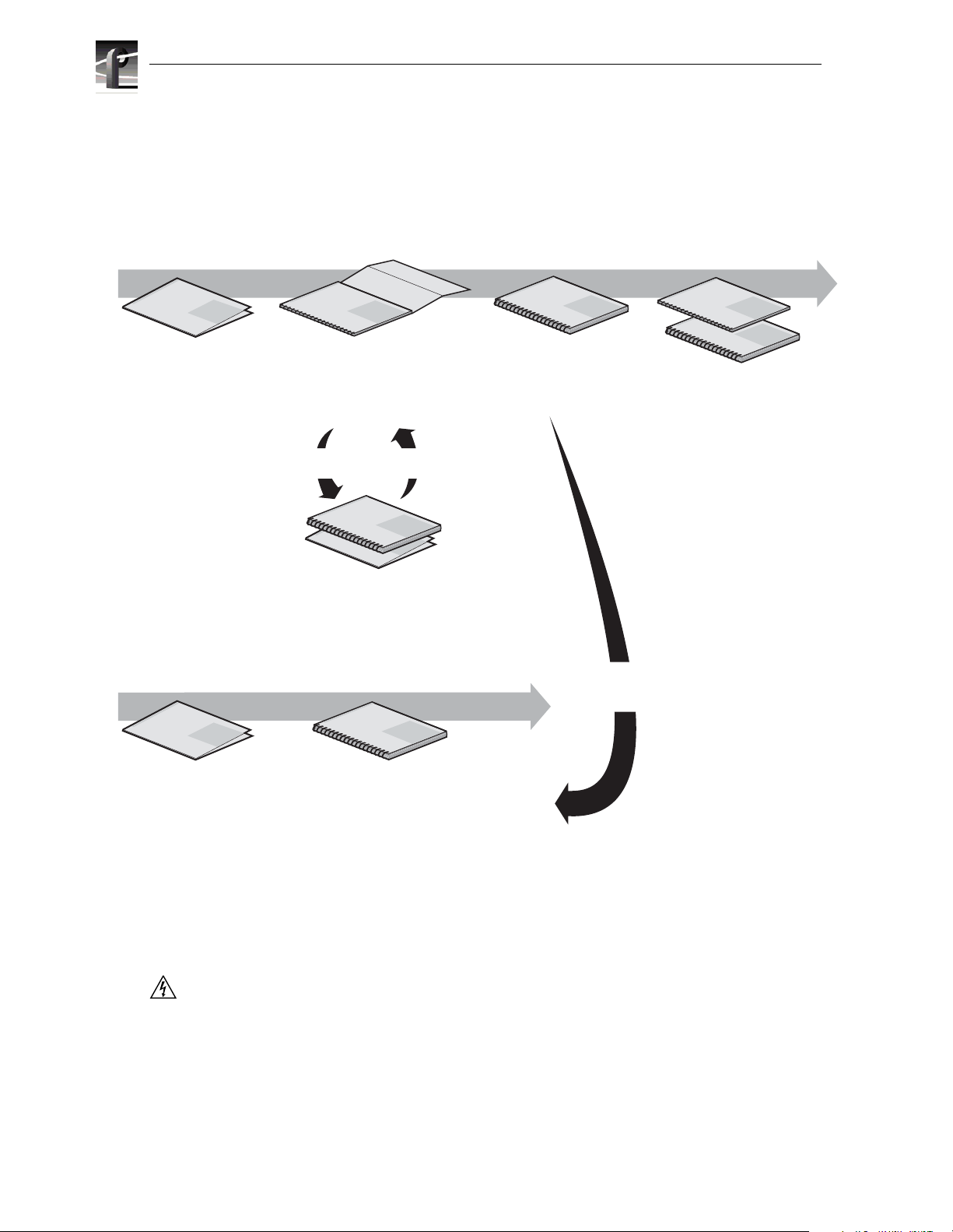
Referring to Related Documentation
This manual is part of a full set of support documentation for the Profile XP Media
Platform. The following illustrates how to use the Profile XP documentation
dependi ng on the task you are performing.
Path for the Installer
s
ie
r
e
S
Profile XP
P
X
f
o
ly
i
m
Manual
a
F
Grass Valley Group
Release Notes
Contains the latest
information about Profile XP
hardware and software
shipped with your system.
Grass Vall
ey Group
Profile XP
Manual
s
e
i
r
e
S
P
X
f
o
y
l
i
m
a
F
Installation Guide
Contains essential steps for
installing your Profile XP
system with local storage,
using factory default settings.
Use alternate procedures
for shared storage option.
s
e
i
r
e
Profile XP
S
P
X
f
o
y
l
i
Manual
m
a
F
Grass Valley Group
System Guide
Contains the product description
and step-by-step instructions for
modifying system settings.
s
e
i
r
Profile XP
e
S
P
X
f
o
y
l
i
Manual
m
a
F
s
e
i
r
e
S
P
X
f
o
Profile XP
y
l
i
Manual
m
a
F
Grass Valley Group
Grass Valley Group
Other Manuals
These manuals include:
- PFC500 Instruction Manual
- PFR500 Instruction Manual
- PFR600 Instruction Manual
- PFR700 Instruction Manual
- Profile XP Service Manual
ey Group
Grass Vall
Grass Valley Group
Profile XP
Profile XP
Manual
P
X
f
o
y
l
i
Manual
m
a
F
ie
r
e
S
P
X
f
o
ly
i
m
a
F
Open SAN
Instruction Manual and Release Notes
Contains instructions for installing storage
that is shared by multiple Profile XP systems.
Path for the Operator
up
s
e
i
r
e
S
Profile XP
P
X
f
o
y
il
m
Manual
a
F
Grass Valley Gro
Release Notes
Contains the latest
information about Profile XP
hardware and software
shipped with your system.
Grass Valley Group
Profile XP
o
y
l
i
Manual
m
a
F
User Manuals
Contains complete instructions for using
Profile applications. These manuals include:
- Profile XP User Manual
- Other user manuals you received with
optional Profile applications.
Referring to Safety Summaries
s
e
i
r
e
S
s
Installers consult
the User Manuals
as needed.
s
e
i
r
e
S
P
X
f
WARNING: Be sure to review all safety p recautions listed in the P rofile XP S ystem
Guide in order to avoid personal injury and prevent damage to this product and its
peripheral products.
4 PVS3000 & PVS3500 Installation Guide 23 February 2004
Page 5

Checking standard accessories
Your Profile XP Media Platform is shipped with several standard accessories as
shown in the table. Locate the accessories you need for your installation and proceed.
Standard PVS3000 Accessories
Keyboard and Mouse Ethernet Cable
I/O Panel and interface cable Windows NT Software Disk and Documentation
Rack-mount slides Profile XP Software CD-ROM and Release Notes
About PVS3000 and PVS3500
The PVS3000 Series introduces the ability to use standard and high definition
hardware in the same Media Platform. Various models provide d ifferent capabilities,
depending on the hardware and software licenses t hat you purchase.
PVS3000
The PVS3000 provides separate SD and HD hardware in a single Media Platform.
You can define SD and HD channels that can run concurrently in your system.
SD channels allow you to record SD clips in MPEG (I-frame, Long GoP, or D-10),
DVCPRO 25, and DVCPRO 50 formats using your standard definition SDI inputs.
You can play clips in any combination of these formats on any SD channel using an
SDI output.
Before getting started
PVS3500
HD channels let you record and play high definition clips with your HD-SDI inputs
and outputs.
The PVS3500 includes an Agile Output software license that enables you to play SD
and HD clips through an H D decoder .
If your Definition Independent HD/SD Player channel includes a standard definition
SDI output, SD clips play out normally, and all HD clips are down-converted to SD
format with the aspect ratio conversion that you set with Configuration Manager.
If your HD/SD Player channel includes an HD-SDI output, HD clips play out
normally, and all SD clips are up-converted to HD format with the aspect ratio
conversion that you se t with Configuration Manager.
NOTE: SD clips must be in MPEG 4:2:0 format to play out on a Definition
Independent channel.
23 February 2004 PVS3000 & PVS3500 Installation Guide 5
Page 6

Before getting star ted
System power-off and reboot procedure
When you power-off or reboot your Profile XP Platform and RAID storage system,
you must follow the proper sequence as described in the following procedure.
NOTE: If your Profile XP Media Platform is part of an Open SAN, disregard this
procedure, and refer to the instructions in the Open SAN Instruction Manual for
shutting down the Open SAN.
1. Power-off the RAID storage system by powering-off the RAID Controller chassis
prior to, or at the same time as the RAID Expansion chassis.
CAUTION: You must alwa ys power off the PFR500 RAID Controller chassis prior
!
to, or at the same time as the PFR500E Expansion Chassis. Failure to do so may
force some LUNs offline. This will cause loss of access to the media file system
when the system is powered on again. Refer to the Profile XP System Guide for
instructions on how to recover from improper power-off sequence.
2. Wait approximately 30 seconds for the disk drives to spin down, then power-on all
RAID Expansion chassis, then all RAID Controller chassis. Always power-on the
RAID Expansion chassis prior to, or at the same time as the RAID Controller
chassis.
3. Wait for RAID storage initialization, as follows:
- PFR700 RAID Storage sy stems - Wait until all disk access LEDs are steady —
approximately 4 minutes. The controller READY LED must be ON, the front
Power LED must be ON, and the front Service LED must be OFF. (Refer to the
PFR700 Instruction Manual to interpret other disk access LED or status LED
behavior.)
- PFR600 RAID Storage sy stems - Wait until all disk access LEDs are steady
green— approximately 4 minutes. The rear panel 7-segment LED displays the
chassis address. (Refer to the PFR 600 Instruction Manual to interpret other disk
access LED or 7-segment LED behavior.)
- PFR500 RAID Storage sy stems - Wait until all disk access LEDs are steady
green— approximately 4 minutes. The rear panel 7-segment LED displays the
chassis address and the HOST RDY light is on. (Refer to the PFR500 Instruction
Manual to interpret other disk access LED or 7-segment LED behavior.)
- PFC500 RAID Storage systems - Wait until the System Check LED is off and all
disk access LEDs are steady green— approximately 2 minutes. (Refer to the
PFC500 Instruction Manual to interpret other front panel LED behavior.)
On the Profile XP Media Platform, shut down and restart the Windows operating
system. Wait for auto-logon as described in “Start your system” on page 17.
6 PVS3000 & PVS3500 Installation Guide 23 February 2004
Page 7
1
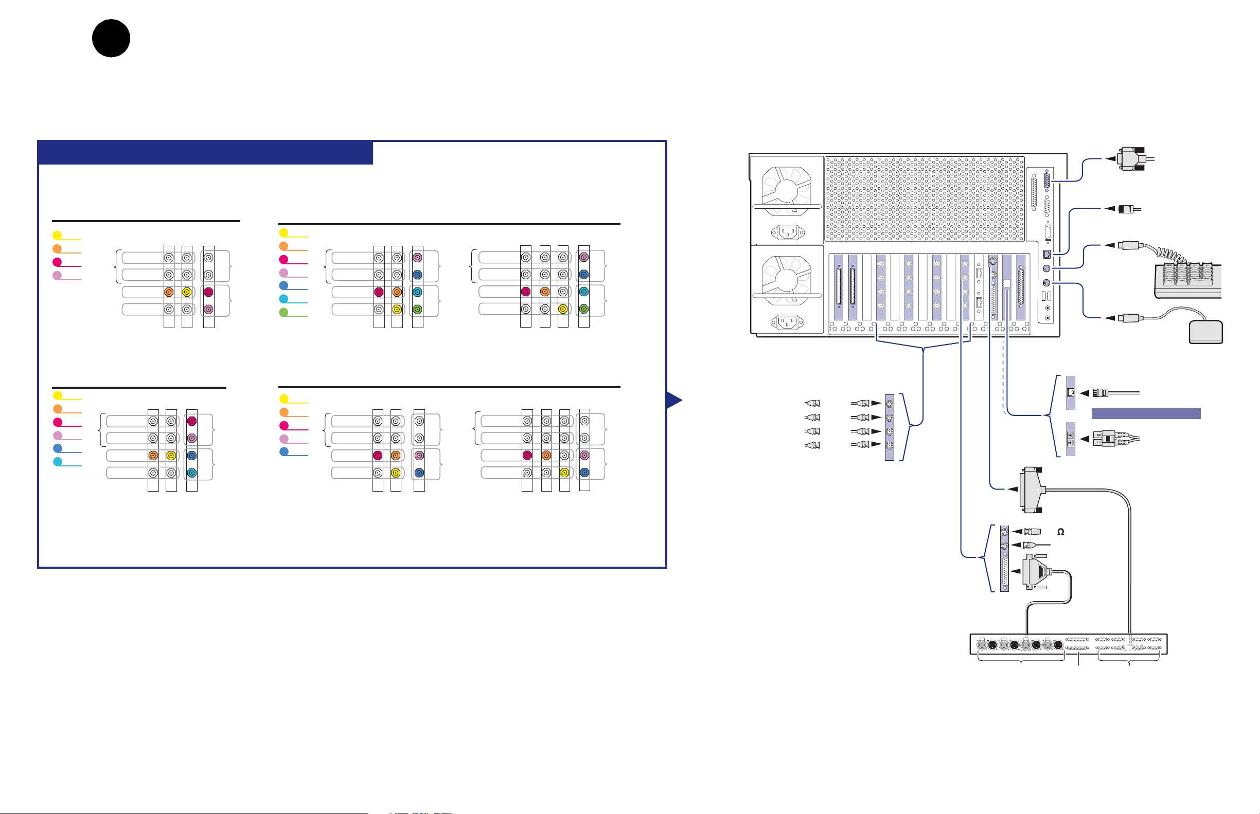
Set up system hardware and connect video
Using the diagrams on this or the follow ing page , set up the syste m hardw are as show n, the n
locate your PVS3000 Series model (PVS3000 or PVS3500) under Default Video
Connecti ons. Use the color coding to make the video I/O co nnections for the recorder and
player channels.
PVS 3000 Default Video Connections
Profile XP Media Platform
SVGA
Monitor
PVS 3004
Channel names Video Connections
Vtr1
Vtr2
Vtr3
Vtr4
NTSC/PAL
Monitor
HD-SDI
SD SDI
Play
Record
SDI
2In/2Out
PVS 3024
Channel names
Vtr1
Vtr2
Vtr3
Vtr4
Vtr5
Vtr6
Monitor
NTSC/PAL
SD SDI
Play
Record
Video Connections
SDI
HD-SDI
2In/2Out
A
B
A
B
PVS 3534
Channel names
Vtr1
Vtr2
A
B
RecordPlay
A
B
Vtr3
Vtr4
Vtr5
Vtr6
Vtr7
Monitor
Video Connections
NTSC/PAL
SD SDI
Play
Record
HD-SDI
SDI
2In/2Out
A
B
A
B
RecordPlay
Monitor
PVS 3014
Channel names
Vtr1
Vtr2
Vtr3
RecordPlay
Vtr4
Vtr5
NTSC/PAL
SD SDI
Monitor
Record
Video Connections
HD-SDI
Play
SDI
2In/2Out
A
B
A
B
RecordPlay
Monitor
Video Connections
with Embedded Audio
HD-SDI
NTSC/PAL
SD SDI
Play
Record
Video Connections
with Embedded Audio
HD-SDI
NTSC/PAL
SD SDI
Play
Record
SDI
2In/2Out
A
B
A
B
SDI
2In/2Out
A
B
A
B
Keyboard
RecordPlay
Mouse
HD SDI
Monitor (NTSC/PAL)
Monitor (SD SDI)
Play (HD Out)
RecordPlay
Record (HD In)
SDI 2In/2Out
In A
In B
Out A
Out B
Ethernet
Windows NT
Network
Ethernet
Video network
AND / OR
Fibre Channel
Video network
RS-422
Notes
:
Video I/Os are assigned beginning with Vtr1 and the HD-SDI board in the lowest numbered board slot. SD clips are upconverted on HD outputs.
SD I/Os are assigned after HD I/Os. SD outputs play down-converted HD clips.
NTSC/PAL and SD SDI connections are for monitoring purposes only.
75 Terminator
Reference In
LTC & GPI
I/O Panel
Push Push Push Push
LTC In/Out RS-422GPI In/Out
23 February 2004 Set up system hardware and connect video 7
Page 8
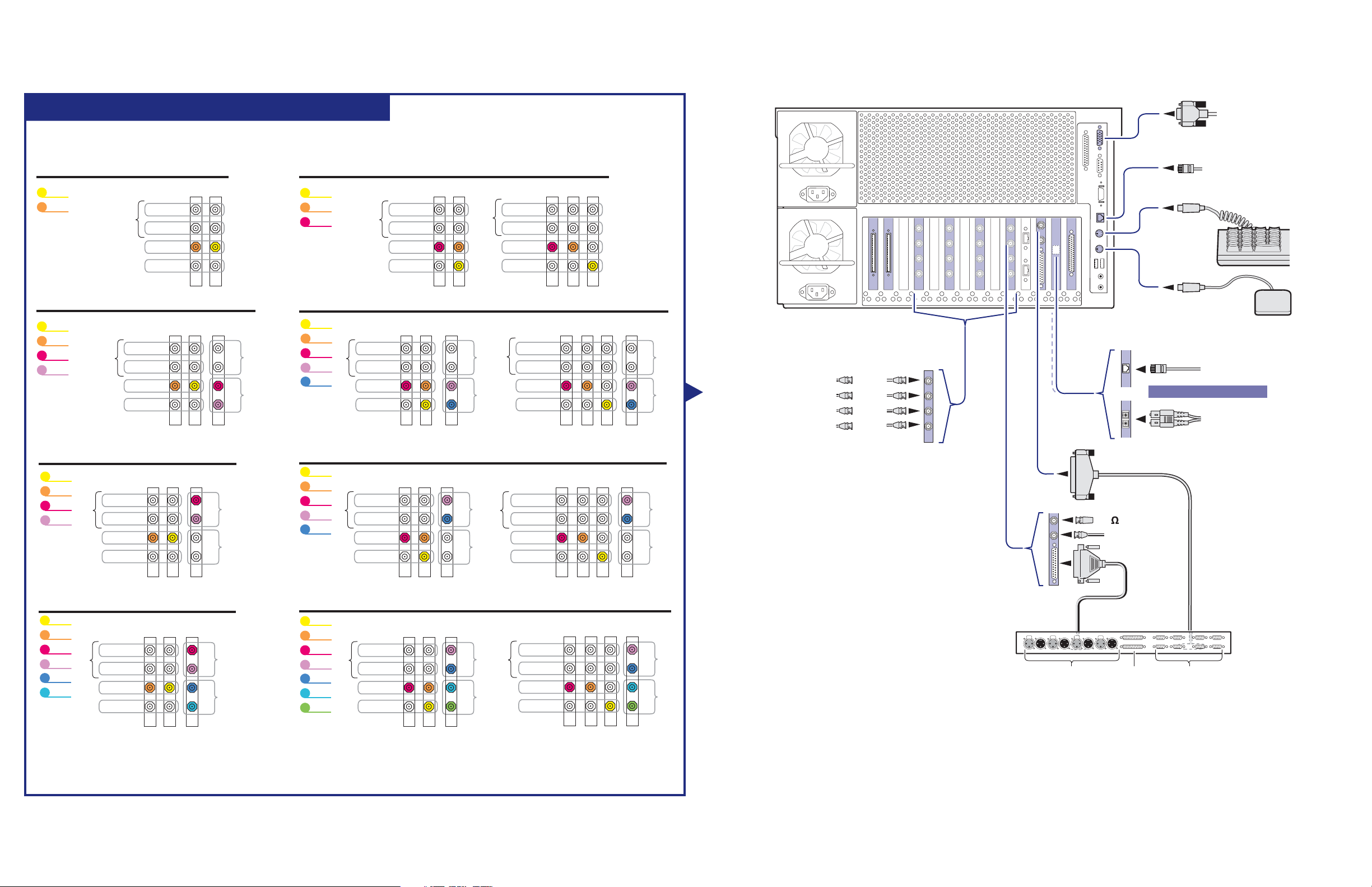
PVS 3500 Default Video Connections
Profile XP Media Platform
SVGA
Monitor
PVS 3502
Channel names
Vtr1
Vtr2
Video Connections
HD-SDI
NTSC/PAL
SD SDI
Monitor
Play
Record
PVS 3504
Channel names Video Connections
Vtr1
Vtr2
Vtr3
Vtr4
NTSC/PAL
Monitor
SD SDI
Record
HD-SDI
Play
PVS 3522
Channel names
Vtr1
Vtr2
Vtr3
Vtr4
Monitor
Video Connections
NTSC/PAL
SD SDI
Play
Record
HD-SDI
SDI
2In/2Out
SDI
2In/2Out
A
B
A
B
A
B
RecordPlay
A
B
PVS 3512
Channel names
Vtr1
Vtr2
Vtr3
Video Connections
NTSC/PAL
SD SDI
Monitor
Play
Record
HD-SDI
Video Connections
with Embedded Audio
NTSC/PAL
SD SDI
Monitor
Play
Record
HD-SDI
Ethernet
Windows NT
Network
Keyboard
Mouse
PVS 3514
Channel names
Vtr1
Vtr2
Vtr3
RecordPlay
Vtr4
Vtr5
NTSC/PAL
SD SDI
Monitor
Record
Video Connections
HD-SDI
Play
SDI
2In/2Out
A
B
A
B
RecordPlay
Monitor
PVS 3532
Channel names
Vtr1
Vtr2
Vtr3
Vtr4
Monitor
Vtr5
NTSC/PAL
SD SDI
Record
Video Connections
HD-SDI
Play
SDI
2In/2Out
A
B
A
B
RecordPlay
Monitor
Video Connections
with Embedded Audio
NTSC/PAL
SD SDI
Play
Record
Video Connections
with Embedded Audio
NTSC/PAL
SD SDI
Play
Record
HD-SDI
HD-SDI
SDI
2In/2Out
A
B
A
B
SDI
2In/2Out
A
B
A
B
RecordPlay
HD SDI
Monitor (NTSC/PAL)
Monitor (SD SDI)
Play (HD Out)
Record (HD In)
SDI 2In/2Out
In A
In B
Out A
Out B
Ethernet
Video network
AND / OR
Fibre Channel
Video network
RS-422
RecordPlay
75 Terminator
Reference In
LTC & GPI
PVS 3524
Channel names
Vtr1
Vtr2
Vtr3
Vtr4
Monitor
Vtr5
Vtr6
Notes
:
Video Connections
NTSC/PAL
SD SDI
Play
Record
HD-SDI
SDI
2In/2Out
A
B
A
B
RecordPlay
PVS 3534
Channel names
Vtr1
Vtr2
Vtr3
Vtr4
Monitor
Vtr5
Vtr6
Vtr7
NTSC/PAL
SD SDI
Play
Record
Video Connections
SDI
HD-SDI
2In/2Out
A
B
A
B
RecordPlay
NTSC/PAL
SD SDI
Monitor
Record
Video Connections
with Embedded Audio
HD-SDI
Play
SDI
2In/2Out
A
B
A
B
I/O Panel
Push Push Push Push
RecordPlay
LTC In/Out RS-422GPI In/Out
Video I/Os are assigned beginning with Vtr1 and the HD-SDI board in the lowest numbered board slot. SD clips are upconverted on HD outputs.
SD I/Os are assigned after HD I/Os. SD outputs play down-converted HD clips.
NTSC/PAL and SD SDI connections are for monitoring purposes only.
8 Set up system hardware and connect video 23 February 2004
Page 9
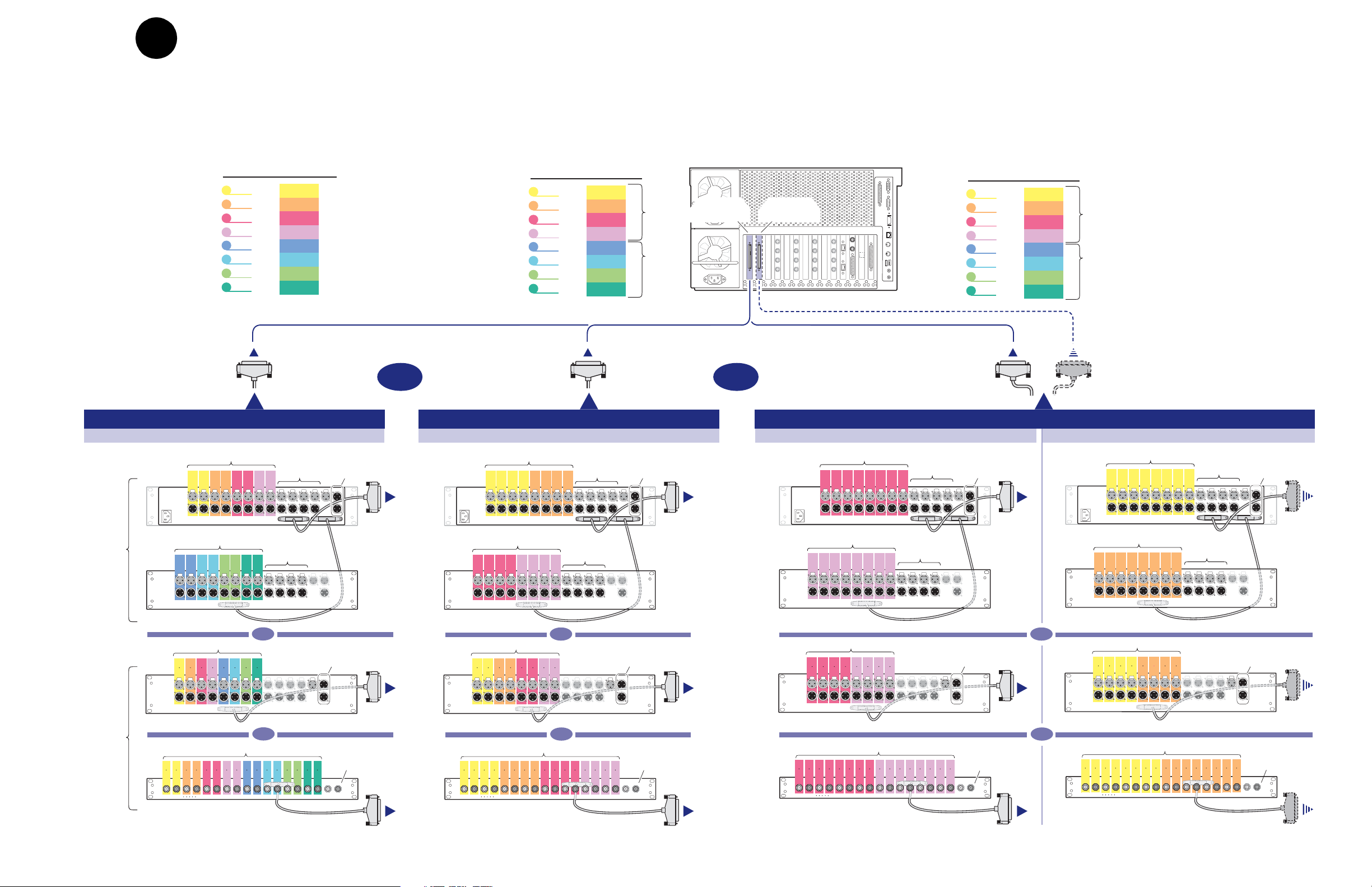
2
Connect audio
Determine if your PVS 3000 Series media platform has one or two audio
boards installed as shown on this diagram, then use the color coding to
determine the audio I/O connections for each vi deo channel for your model.
Channel
Names
Vtr1
Vtr2
Vtr3
Vtr4
Vtr5
Vtr6
Vtr7
Vtr8
Audio I/O
Assignments
1 - 2
3 - 4
5 - 6
7 - 8
9 - 10
11 - 12
13 - 14
15 - 16
Audio I/O Connections: One Audio Board Installed
PVS 3014, 3024, 3034, 3514, 3524, 3532, 3534
Analog
1 2 3 4 5 6 7 8
Push Push Push Push Push Push Push Push Push Push Push Push Push
In
Out
Digital
9-16
Monitor
Channel
Names
Vtr1
Vtr2
Vtr3
Vtr4
Vtr5
Vtr6
Vtr7
Vtr8
Audio I/O
Assignments
1 - 4
5 - 8
9 - 12
13 - 16
1 - 4
5 - 8
9 - 12
13 - 16
Opt.
Bd
Std.
Bd
Profile XP Media Platform
Audio Board
Audio I/O Connections: One Audio Board Installed
PVS 3004, 3502, 3504, 3512, 3522
Analog
1 2 3 4 5 6 7 8
Push Push Push Push Push Push Push Push Push Push Push Push Push
In
Out
Digital
9-16
Monitor
Standard
OROR
Channel
Names
Audio I/O
Assignments
Vtr1
Optional
Audio Board
Vtr2
Vtr3
Vtr4
9 - 12
13 - 16
Vtr5
Vtr6
Vtr7
Vtr8
9 - 12
13 - 16
Audio I/O Connections: Two Audio Boards Installed
Analog
1 2 3 4 5 6 7 8
Push Push Push Push Push Push Push Push Push Push Push Push Push
In
Out
Digital
9-16
Monitor
1 - 4
5 - 8
1 - 4
5 - 8
Opt.
Bd
Std.
Bd
To Optional Audio BoardTo Standard Audio Board
Analog
1 2 3 4 5 6 7 8
Push Push Push Push Push Push Push Push Push Push Push Push Push
In
Out
Digital
9-16
Monitor
OR
OR
PAC216
In
Out
Analog
9 10 11 12 13 14 15 16
PROFILE
PACXLR
Digital
123456789101112131415
Push Push Push Push Push Push Push Push Push Push Push Push Push
In
Out
16
PROFILE
XLR216
Digital
12123434565678789109101112111213141314151615
Out
In
BNC216
Digital
1-8
Push PushPush Push Push Push Push Push Push Push Push Push Push Push
16
Out
In
AES/EBU
Monitor
Mon
Out
Profile Audio
Chassis (PAC)
AES/EBU
Breakout
Panels
PAC216
In
Out
Analog
9 10 11 12 13 14 15 16
PROFILE
PACXLR
OR
Digital
123456789101112131415
Push Push Push Push Push Push Push Push Push Push Push Push Push
In
Out
16
PROFILE
XLR216
OR
Digital
12123434565678789109101112111213141314151615
Out
In
BNC216
Digital
1-8
Push PushPush Push Push Push Push Push Push Push Push Push Push Push
AES/EBU
16
Out
In
Monitor
Mon
Out
PAC216
In
Out
Analog
9 10 11 12 13 14 15 16
PROFILE
Digital
PACXLR
OR
Digital
123456789101112131415
Push Push Push Push Push Push Push Push Push Push Push Push Push
In
Out
16
PROFILE
XLR216
OR
Digital
12123434565678789109101112111213141314151615
Out
In
BNC216
1-8
Push PushPush Push Push Push Push Push Push Push Push Push Push Push
AES/EBU
16
Out
In
Monitor
Mon
Out
PAC216
In
Out
Analog
9 10 11 12 13 14 15 16
PROFILE
Digital
PACXLR
Digital
123456789101112131415
Push Push Push Push Push Push Push Push Push Push Push Push Push
In
Out
16
PROFILE
XLR216
Digital
12123434565678789109101112111213141314151615
Out
In
BNC216
1-8
Push PushPush Push Push Push Push Push Push Push Push Push Push Push
16
Out
In
AES/EBU
Monitor
Mon
Out
23 February 2004 Connect audio 9
Page 10
#
0
2 3
0
7
6
5
4
3
2
1
0
E
C
A
8
6
4
2
F
D
B
9
7
5
3
1
IMPORTANT: If you are installing your PVS3000 Series (PVS3000 or PVS3000 Series)as part of an
Open SAN, do not perform this RAID storage setup. Instead, follow the instructions in the
Instruction Manual
for setting up RAID storage.
Open SAN
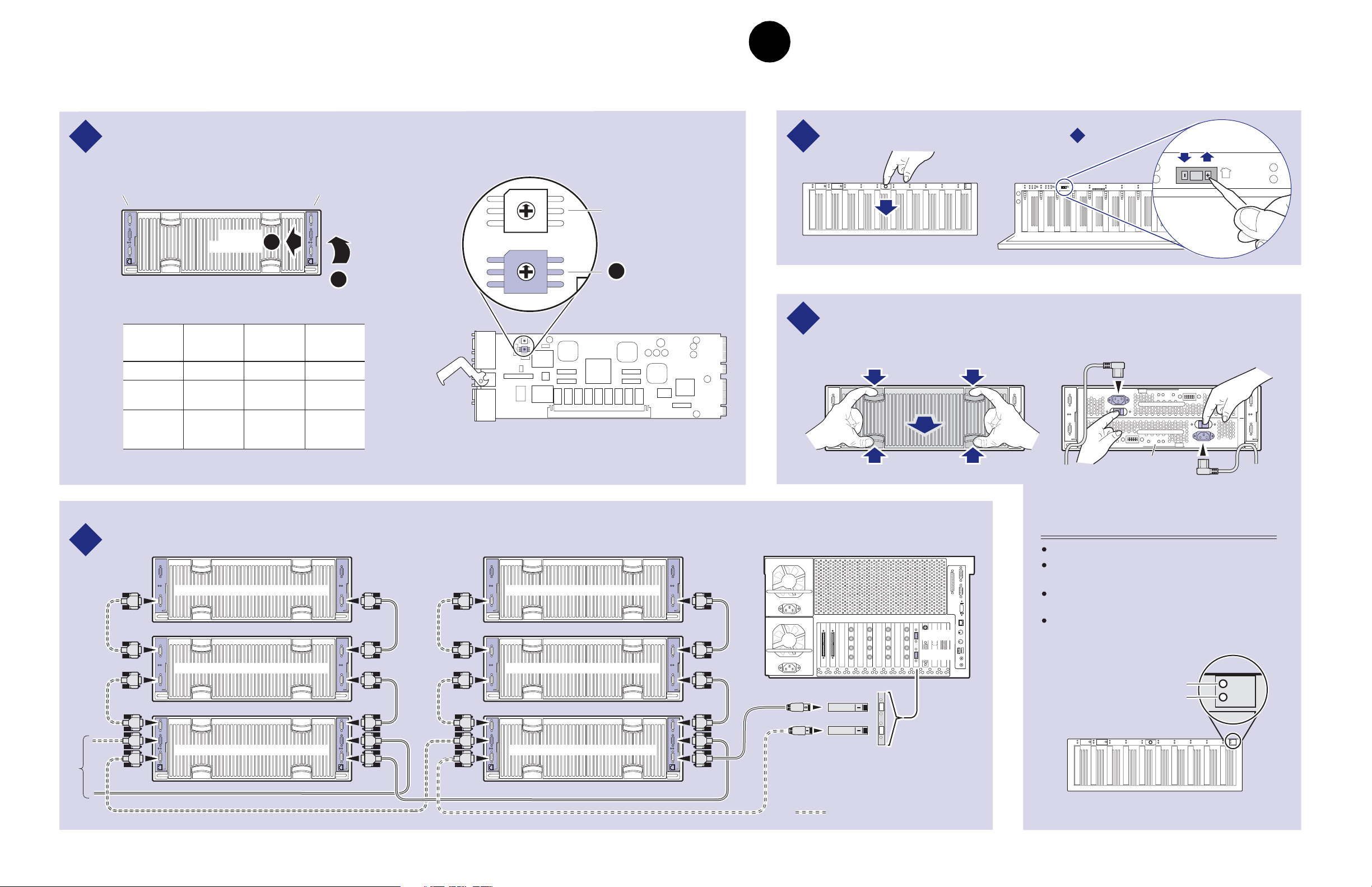
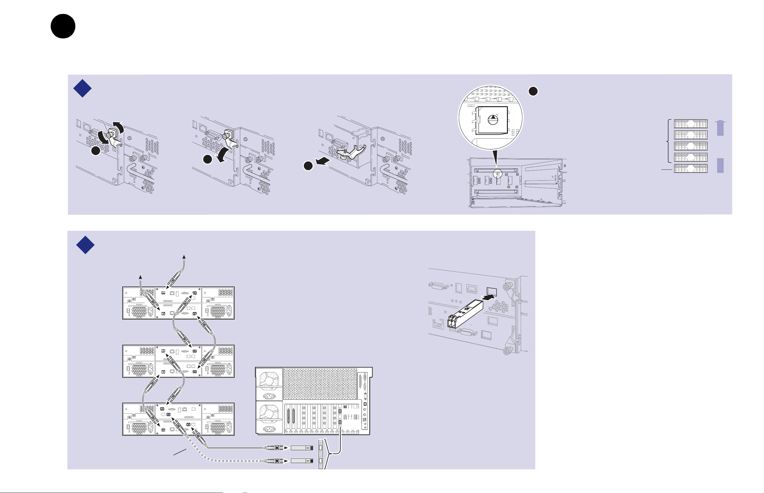
Set up RAID Storage: PFC500/E
3
(Local storage only)
Use this diagram to set up the PFC500 Fibre Channel RAID Chassis and the PFC500E
Expansion Chassis (if used).
Set the Fibre Channel Loop Address ID on each RAID Controller as shown.
1
Optional Redundant
RAID Controller
Primary
RAID Controller
PFC 500 Rear Panel
Pull out
controller
B
A
Lift handle
Fibre Channel Loop Addresses
Number of
PFC
500s *
1
2
3
PFC 500
Chassis
First
First
Second
First
Second
Third
Controller
Address ID
0
0
1
0
1
2
* For systems with greater than three PFC500s, use the
same numbering pattern as shown.
Primary
Redundant
Controller
Address ID
1
2
3
3
4
5
Set required chassis addresses, refer to Step .
3
2
Lower the
front door
024
Top Switch
(always set to "0")
6810
#
#
0 1 2 3 4 5 6 7 8 9
135
7911
024
6810
1
#
# #
135
7911
0 1 2 3 4 5 6 7 8 9
Set Chassis
Addresses
Set Fibre Channel
Loop Address ID
C
settings. Refer to
the table.
Connect power cords and turn on power as shown.
RAID Controller Board
0
1
7
2
6
3
5
4
0
1
F
2
3
E
4
D
5
C
6
B
7
A
9
8
4
Begin with PFC
500E(s), if installed. Verify proper power-up as shown.
Power Cord (115V/230V)
l
0
ON
OFF
OFF
ON
0
l
P/S
A
B
Optional
Power Supply
Power Cord
(115V/230V)
Power-up Verification
Connect Fibre Channel cabling.
2
* If Installed
PFC 500E* Chassis Address = 2
PFC 500E* Chassis Address = 1
500 Chassis
PFC 500* Chassis Address = 0
Maximum of 5 PFC
10 Set up RAID Storage: PFC500/E (Local storage only) 23 February 2004
PFC 500E* Chassis Address = 2
PFC 500E* Chassis Address = 1
PFC 500 Chassis Address = 0
Media Platform
Copper SFPs
Port A
Port B
Redundant system cabling
Power LED is on.
System Check LED turns off after approximately 90
seconds.
The PFC500 requires approximately 2 to 3 minutes
to fully initialize. All disk access LEDs are on.
Refer to the
PFC 500 Instruction Manual
a problem.
System Check LED
Power LED
024
6810
#
#
0 1 2 3 4 5 6 7 8 9
135
7911
if there is
0626-13
Page 11
0
1
2
3
4
5
6
7
8
9
33a3a
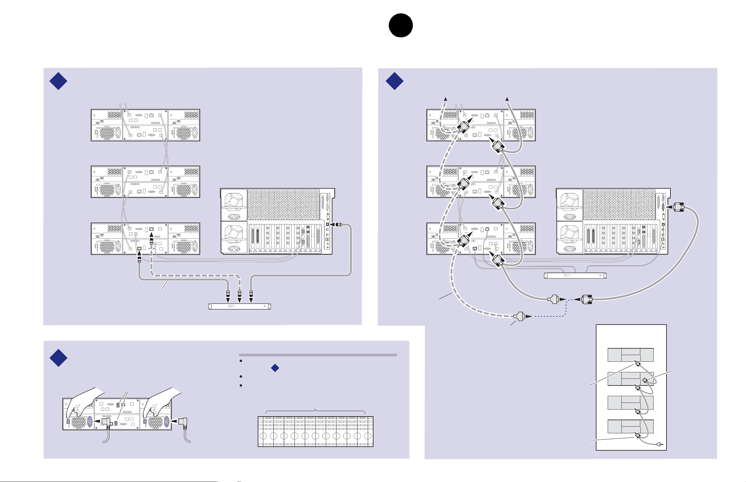
Set up the RAID Storage: PFR500/E
(Local storage only)
3b
Use this diagram to set up the PFR500/E chassis addresses and to connect Fibre
Channel cabling, then proc eed to step 3b on the ne xt page.
IMPORTANT: If you are installing your PVS3000 as part of an Open SAN, do not
perform this RAID storage setup. Instead, follow the instructions in the
Instruction Manual
for setting up RAID storage.
Open SAN
Set chassis addresses on all PFR 500E Expansion Chassis.
1
Loosen
retaining screws
A
B
Install all SFPs and GBICs provided so that you can connect Fibre Channel cabling as shown.
2
Maximum of 9 Expansion Chassis
C
Installing a GBIC
(Gigabit Interface Converter)
D
Remove both Loop Bypass
Board modules to access the
chassis address switch on the
midplane board. Set the switch
to the appropriate address as
shown in the Chassis Address
diagram.
PFR 500E RAID
Expansion Chassis
(if installed)
PFR 500 RAID
Controller Chassis
(factory set to "0")
Chassis Addresses
9
8
7
6
Order of
5
4
3
2
1
0
daisy
chain
* If Installed
PFR 500E*
Expansion
Chassis
PFR 500E*
Expansion
Chassis
PFR 500
RAID
Chassis
23 February 2004 Set up the RAID Storage: PFR500/E (Local storage only) 11
This cable, SFP, and GBIC used for
PFR 500s with optional RAID Controller B.
Media Platform
Port A
Port B
Copper SFPs
Page 12
IMPORTANT: If you are install ing your PVS3000 as part of a M edia Area Network, do not
perform this RAID storage setup. Instead, follow the instructions in the
Instruction Manual
for setting up RAID storage.
Open SAN
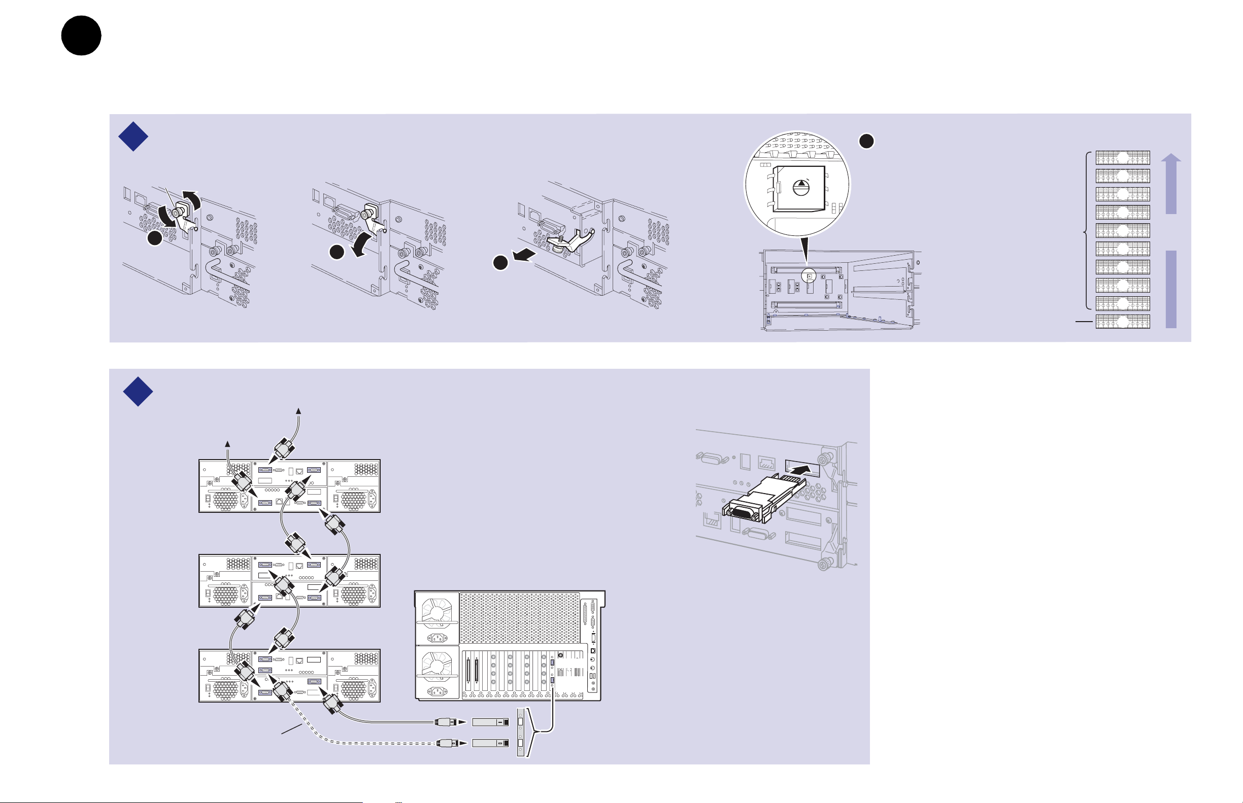
3b
Set up RAID Storage: PFR500/E
(Local storage only)
Use this diagram to c onne ct Ethernet and serial i nterface cabling req uired for monito rin g the
PFR500/E with NetCentral Lite or NetCentral Manager.
Install ethernet cabling and switch or hub as shown.
3
Maximum of 9 Expansion Chassis
* If Installed
PFR 500E*
Expansion
Chassis
PFR 500E*
Expansion
Chassis
PFR 500
RAID
Chassis
Media Platform
Install serial cabling as shown.
4
Caution: See serial cabling detail below.
PFR 500E*
Expansion
Chassis
PFR 500E*
Expansion
Chassis
PFR 500
RAID
Chassis
Media Platform
Standard
This cable used for PFR500s
with optional RAID Controller B.
Ethernet Hub or Switch
Connect power cords, and turn on power as shown.
You must power-up the PFR500E Expansion chassis
5
prior to, or at the same time as the PFR500 RAID
Controller chassis. Verify power-up as shown.
7 Segment
LEDs
Power Cord
(115V/230V)
12 Set up RAID Storage: PFR500/E (Local storage only) 23 February 2004
HOST RDY
Power Cord
(115V/230V)
Power-up Verification
Rear panel "7 Segment LED" displays the chassis address as
set in step .
All disk drive LEDs are green after approximately 3 minutes.
All HOST RDY LEDs are green after approximately 3 minutes.
Refer to the PFR 500 Instruction Manual if there is a problem.
1
Disk Drive LEDs
This cable used for
PFR500s with optional
RAID Controller B.
After RAID Controller A is configured,
the standard serial cable will be moved
to this connector to configure RAID
Controller B, if installed.
Always plug the first connector
into the PFR500 RAID Controller.
Serial Cabling Detail
(Applies to primary and
redundant cabling)
Always plug the end
connector of dasiy
chain cable into last
expansion chassis.
Serial Cable
Leave
unconnected
0626-16
Page 13
0
1
2
3
4
5
6
7
8
9
3
3c
a
Set up the RAID Storage: PFR600/E
(Local storage only)
Use this diagram to set up th e PFR600/E ch assi s addresses and to connect Fibre
Channel cabl in g, the n proceed to step 3d on the next page.
Set chassis addresses on all PFR 600E Expansion Chassis.
1
IMPORTANT: If you are installing your PVS3000 as part of an Open SAN, do not
perform this RAID storage setup. Instead, follow the instructions in the
Instruction Manual
for setting up RAID storage.
Open SAN
D
Loosen
retaining screws
A
Install all SFPs provided so that you can connect Fibre Channel cabling as shown.
2
* If Installed
B
Maximum of 4 Expansion Chassis
C
Remove both Loop Bypass
Board modules to access the
chassis address switch on the
midplane board. Set the switch
to the appropriate address as
shown in the Chassis Address
diagram.
Installing an SFP
(Small Form-Factor Pluggable Interface)
PFR 600E RAID
Expansion Chassis
(if installed)
PFR 600E RAID
Controller Chassis
(factory set to "0")
Chassis Addresses
4
3
Order of
2
1
0
daisy
chain
PFR 600E*
Expansion
Chassis
PFR 600E*
Expansion
Chassis
PFR 600
RAID
Chassis
23 February 2004 Set up the RAID Storage: PFR600/E (Local storage only) 13
This cable and SFP used for PFR 600s
with optional RAID Controller B.
Media Platform
Port A
Port B
Optical SFPs
Page 14
IMPORTANT: If you are installing your PVS3000 as part of an Open SAN, do not perform
this RAID storage setup. Instead, follow the instructions in the
Manual
for setting up RAID storage.
Open SAN Instruction
3d
Set up RAID Storage: PFR600/E
(Local storage only)
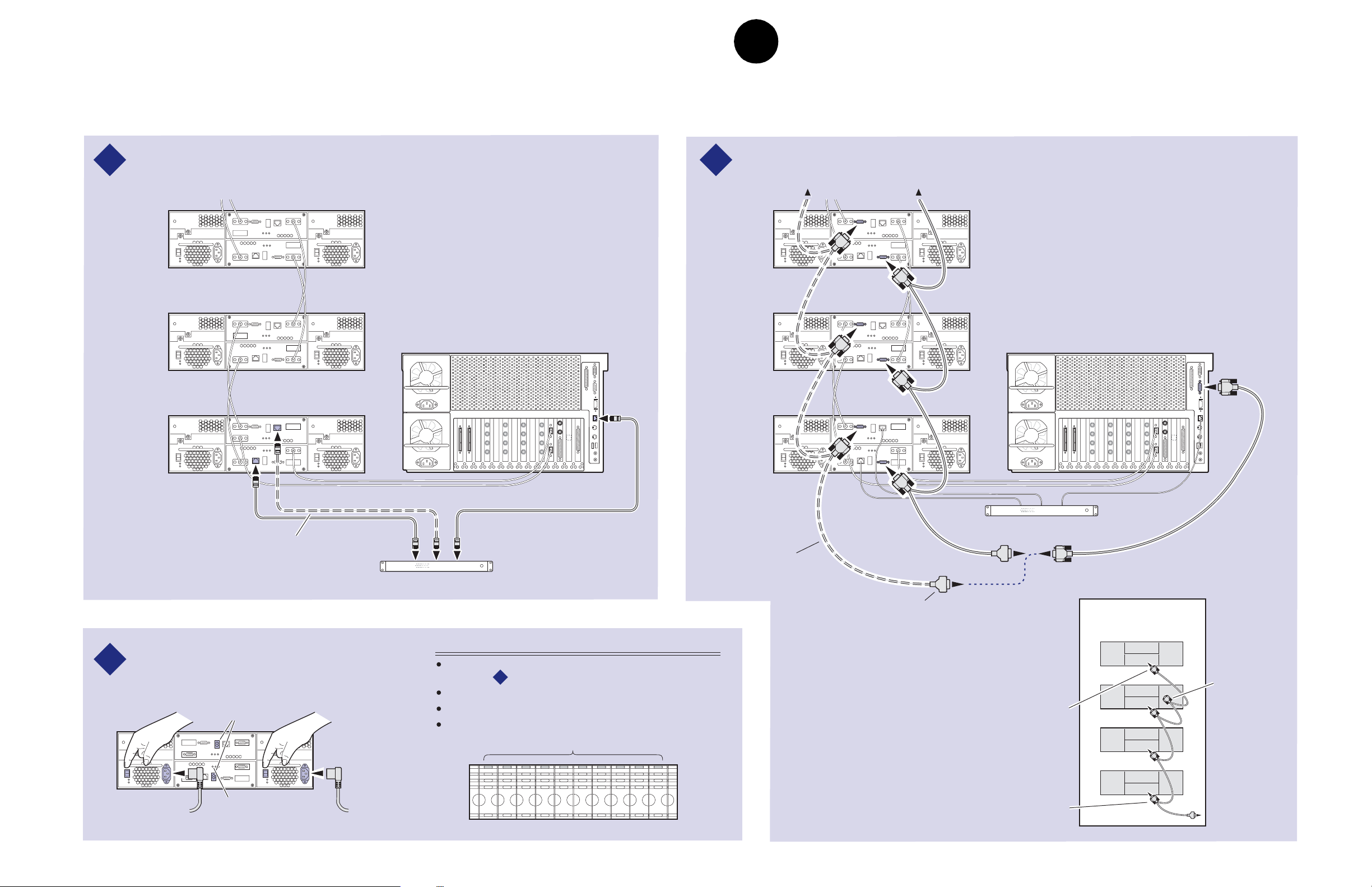
Use this diagram to connect Eth ernet and serial int erface cabli ng re quired for monitoring the
PFR600/E w it h Net Ce ntral Lite or NetC ent ral Manager and micro code updates.
Install ethernet cabling and switch or hub as shown.
3
Maximum of 4 Expansion Chassis
* If Installed
PFR 600E*
Expansion
Chassis
PFR 600E*
Expansion
Chassis
PFR 600
RAID
Chassis
Media Platform
Install serial cabling as shown.
4
Caution: See serial cabling detail below.
PFR 600E*
Expansion
Chassis
PFR 600E*
Expansion
Chassis
PFR 600
RAID
Chassis
Media Platform
Standard
This cable used for PFR 600s
with optional RAID Controller B.
Ethernet Hub or Switch
Connect power cords, and turn on power as shown.
You must power-up the PFR
5
chassis prior to, or at the same time as the PFR
RAID Controller chassis. Verify power-up as shown.
7 Segment
LEDs
Power Cord
(115V/230V)
14 Set up RAID Storage: PFR600/E (Local storage only) 23 February 2004
600E Expansion
Power Cord
(115V/230V)
600
Power-up Verification
Rear panel "7 Segment LED" displays the chassis address as
set in step .
All disk drive LEDs are green after approximately 3 minutes.
Refer to the PFR 600 Instruction Manual if there is a problem.
1
Disk Drive LEDs
This cable used for
PFR 600 chassis with optional
RAID Controller B.
After RAID Controller A is configured,
the standard serial cable will be moved
to this connector to configure RAID
Serial Cabling Detail
(Applies to primary and
redundant cabling)
Controller B, if installed.
Always plug the end
connector of dasiy
chain cable into last
expansion chassis.
Always plug the first connector
into the PFR 600 RAID Controller.
Serial Cable
Leave
unconnected
Page 15
3
3e
a
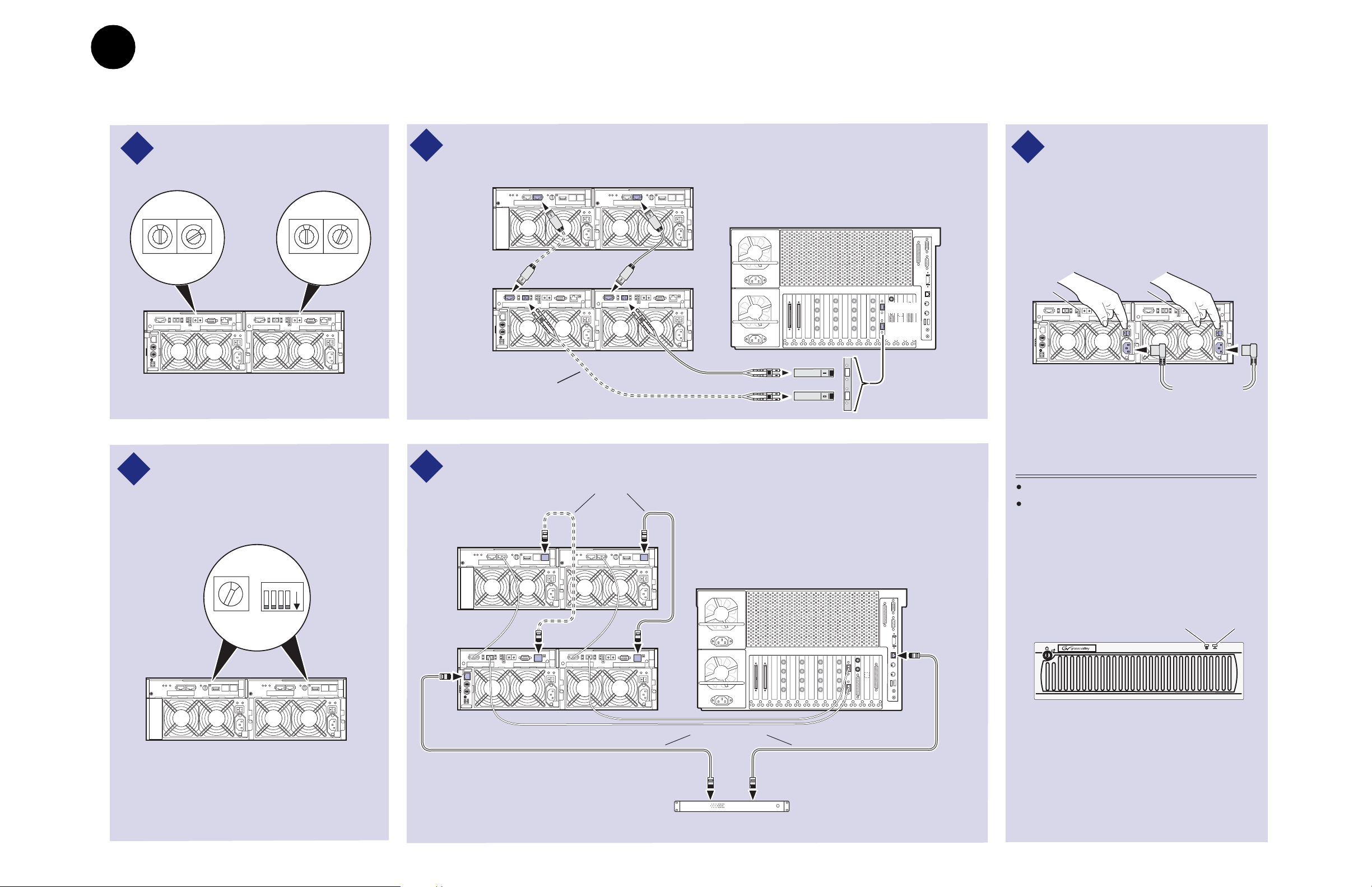
Set up the RAID Storage: PFR700/E
(Local storage only)
Use this diagram to set up th e PFR700/E Fib re Channel addre sses and to connect
Fibre Channel, Ethe rnet, and diagnost ic ca bli ng.
IMPORTANT: If you are installing your PVS3000 as part of an Open SAN, do not
perform this RAID storage setup. Instead, follow the instructions in the
Instruction Manual
for setting up RAID storage.
Open SAN
1
Set Fibre Channel addresses on both
PFR 700 controllers.
0
Address ID = 2*
*If Installed
2
Set the same Chassis Address and
2
diagnostic ID on both PFR 700E
Expansion Adapters, if installed.
0
Address ID = 1
Connect Fibre Channel cabling as shown.
3
* If Installed
Maximum of 1 Expansion Chassis
Connect power cords, and turn on
5
power as shown. You must power-up
the PFR
700E Expansion chassis prior
to, or at the same time as the PFR
700
RAID Controller chassis. Verify power-
PFR 700E*
Expansion
1
Chassis
PFR 700
RAID
Chassis
This cable and SFP used for PFR 700
with optional RAID Controller 1.
Install Ethernet and diagnostic cabling as shown.
4
Diagnostic cables*
Media Platform
Port A
Port B
Optical SFPs
* If Installed
PFR 700E*
Expansion
Chassis
up as shown.
Ready
LED
Ready
LED
Power Cords
(115V/230V)
Power-up Verification
Ready LEDs on RAID controllers are steady ON.
Front panel Power LED is ON, Service LED is OFF
after approximately 3 minutes.
Refer to the PFR 700 Instruction Manual if there is a
problem.
1
4 3 2 1ON
Chassis
Address = 1
23 February 2004 Set up the RAID Storage: PFR700/E (Local storage only) 15
ID = "0"
PFR 700
RAID Chassis
Media Platform
Ethernet cables
Ethernet Hub or Switch
Power LED
PFR
Service LED
700
!
SERVICE
POWER
Page 16

16 Set up the RAID Storage: PFR700/E (Local storage only) 23 February 2004
Page 17

4
1
Start your system
IMPORTANT: If you are installing your Profile XP Media Platform as part of an
Open SAN, disregard this step. Instead, follow the instructions in the Open SAN
Instruction Manual for starti ng your Profile XP Media Platform.
To start your system:
1. Connect power cords to the Profile XP Media Platform and all peripheral devices.
Standard
Power Supply
Power
Cord(s)
(115V/230V)
2. Turn on power to all peripheral devices connected to the Profile XP Media Platform.
NOTE: Do not power-on the Profile XP Media Platform until the RAID storage
system is fully initialized. Refer to RAID storage power-up verification steps on
pages 10-15.
3. Turn on the Profile XP Media Platform using the front panel standby switch, and wait
for Windows NT to initialize and perform auto-logon. The Windows NT desktop will
appear after successful auto-logon.
During initialization, the Profile XP system software checks the RAID storage
system for a video file system. Since at first power-up one is not found, an error
message may be displayed regarding loss of the video file syst em .
Proceed with the next procedure to create a new video file system.
NOTE: You must use the proper power-off sequence when turning off or rebooting
the Profile XP Platform and RAID storage system. Refer to “System power-off and
reboot procedure” on page 6.
Optional
Power Supply
Option
RD only
0626-14
23 February 2004 PVS3000 & PVS3500 Installation Guide 17
Page 18

Start your system
18 PVS3000 & PVS3500 Installation Guide 23 February 2004
Page 19

5
181
Create a video file system
IMPORTANT: If you are installing your Profile XP Media Platform as part of an
Open SAN, disregard this step. Instead, follow the instructions in the Open SAN
Instruction Manual for starti ng your Profile XP Media Platform.
Before you can use your Profile XP Media Platform system, you must create a video
file system on the Fibre Channel RAID Chassis using the Disk Utility.
NOTE: If you want to configure some drives as hot spare drives, do not perform this
procedure. Instead, perform the procedures found in Chapter 3 of the Profile XP
System Guide in the section titled “Configuring RAID storage using GVG Disk
Utility”, then proceed with the next procedure in this guide.
To create a video file system:
1. Start Configuration Manager usin g the desktop shortcut or by select ing
Programs | Profile Applications | Configuration Manager. The Configuration Ma na ge r
dialog box appears.
Start |
2. Click
23 February 2004 PVS3000 & PVS3500 Installation Guide 19
File System to start the GVG Disk Utility.
Page 20

Create a vid eo file system
3. If you are configuring a PFR500 or PFR600 storage system, perform the following
steps to set the Fibre Channel ID, otherwise, proceed to step 4.
a. Expand the tree view and right-click the
PFR600, then select
Set Fibre Channel ID in the context menu.
b. In the Set Fibre Channel ID dialog box, enter IDs as shown, then click
c. Click
OK in the Operation Successful dialog box.
Controller0 icon under PFR500 or
OK.
d. Cycle the power on the RAID Controller chassis. Leave the power off for about
30 seconds before powering on again. You can leave the Expansion chassis
powered on during this time.
e. After the RAID Controller chassis has finished initializing, restart the
Windows NT operating system on the Profile XP Platform.
f. Start Configuration Manager using the desktop shortcut or by selecting
Programs | Profile Applications | Configuration Manager.
Start |
g. In Configurati on Manager dialo g box appears. cli ck
File System to start the GVG
Disk Utility.
4. Expand the tree view and ide ntify bound LUNs and unbound disks by the ir
placement in the hierarchy of the tree view.
5. If there are unbound LUNs displayed in the tree view, you must perform the following
steps, otherwise, proceed to step 6.
a. To bind unbo und disks, right-cli ck the
Bind LUNs in the context menu. Peer controllers that share the same set of disks
Unbound n ode for a controller, then select
are automatically selected as a pair.
The Binding LUN… dialog box opens showing all unbound disks for the
controller listed in the Available Disk list.
20 PVS3000 & PVS3500 Installation Guide 23 February 2004
Page 21

Create a video file syst em
b. Select RAID 3 usin g the LUN TYPE drop-down box.
c. Select five contiguous disks, then click the add button to add them to the
Selected Disks list. (TIP: Use ‘shift-click’ to select disks.)
d. Click
OK to close t he Bindi ng LUN… d ialog bo x and beg in the bi nding p rocess.
The Progress Report dialog box opens, showing the status of the binding
process.
e. R e pea t st ep a through step d for a ll un bo un d di s ks on al l rema ini n g c on trollers
displayed in the tree view.
NOTE: PFR500 and PFR600 controllers take less than a min u te to bind a LU N,
but can bind only one LUN at a time. You must wait until binding is completed
before binding the next LUN. PFC500 and PFR700 controllers take several hours
to bind a LUN, but allow multiple binding processes at the same time.
f. Upon 100% completion, click
Close in Progress Report window.
NOTE: Do not proceed until all LUNs are finished binding.
g. Restart the Windows NT operating system on the Profile XP Platform.
h. Start Configuration Manager using the desktop shortcut or by selecting
Programs | Profile Applications | Configuration Manager.
i. In Configuration Manager, click
6. In the GVG Disk Utility main menu, click
File System to start the GVG Disk Utility.
Tools | Make File Sys tem. The File System
Start |
wizard appears.
23 February 2004 PVS3000 & PVS3500 Installation Guide 21
Page 22

Create a vid eo file system
7. Enter a volume name or accept the default name, then click Next.
8. Select
9. Click
Yes, create a file system using all RAID3 LUNs, then click Finish.
OK, in the warning message box. The Progress Report window appears showing
the create file system task status.
22 PVS3000 & PVS3500 Installation Guide 23 February 2004
Page 23

Create a video file syst em
10.Upon 100% completion, click Close in Progress Report window.
11.When the reboot message a ppears, click
OK, then restart the Windows NT
operating system on the Profile XP Platform.
12.Continue with the next procedure in this guide.
23 February 2004 PVS3000 & PVS3500 Installation Guide 23
Page 24

Create a vid eo file system
24 PVS3000 & PVS3500 Installation Guide 23 February 2004
Page 25

Set up PFR500 or PFR600 network
6
151
Modifyin g network and SNMP settings on RAID Controller A
settings
This procedure explains how to modify factory default PFR500 or PFR600 network
and SNMP settings for monitoring with NetCentral Lite or NetCentral Manager. This
step is not required for PFC500 RAID storage systems.
NOTE: Disregard this step if you are connecting one Profile XP Platform and
PFC500 RAID storage system to a network using factory default network settings.
Proceed to “Start NetCentral Lite monitoring software” on page 33.
PFR500 or PFR600 network is set up using a console program accessed through the
serial port on the RAID Controller and Hyperterminal, running on the Profile XP
system. Both RAID controllers must be configured if the optional RAID Controller B
is installed. Refer to the Profile XP Service Manual for information on using
NetCentral Lite.
This proced ur e as sum es t he PF R500 or PFR600 is cabled and powe re d-up as sho wn
on pages 11 and 12 or pages 13 and 14.
To configure PFR500 or PFR600 network and SNMP settings:
1. Start a Hyperterminal session using the following steps:
a. Click
b. In the Connection Description dialog box, type pfr, then click
c. In the Connect To dialog box, click
d. In the Com1 Properties dialog box, click
2. Use the instructions in the following table to modify RAID controller settings.
Start | Programs | Accessories | Hyperterminal | HyperTerminal.
OK.
OK.
Restore Default s, then click OK. (9600,
8 bits, parity none, stop bi t 1, flo w cont rol no ne) A fl ashing cursor appea rs in t he
terminal window.
23 February 2004 PVS3000 & PVS3500 Installation Guide 25
Page 26

Set up PFR500 or PFR6 00 ne tw ork settings
reboot
>>> CAUTION: Use only the PFR500 and PFR600 commands specified in this procedure.
Modifying some system parameters may render your RAID chassis inoperable.
Instructions Text entered and displayed in terminal window
Press Enter to receive the
command prompt, then type
reboot, and press Enter.
NOTE: If you fail to receive
the command prompt, check
cabling and verify Hyper
Terminal setup. Try cycling
the power on the RAID
Controller chassis. You can
leave the Expansion chassis
on. The boot screen should
appear.
The boot screen appears. After
default settings are displayed,
press any key within 10 sec,
otherwise, the RAID
controller will initialize and
display a command prompt.
NOTE: If you miss the 10
second window, type
reboot again when the
command prompt appears,
then press Enter, or try
cycling the power on the
RAID Controller chassis.
You can leave the Expansion
chassis on. The boot screen
should appear.
Press Enter to modify
settings.
Ciprico#
Rebooting now - this will kill this shell.
Ciprico Web Manager
Copyright Ciprico Inc. 2000
-------------------------------------------------------------------------NETWORK INTERFACE PARAMETERS:
IP address on LAN is 192.168.0.11
LAN interface's subnet mask is 255.255.255.0
COMMUNICATION PARAMETERS:
Serial channels will use a baud rate of 9600
HARDWARE PARAMETERS:
This board's MAC Address is 0:20:46:11:14:23
APPLI CATION PARA M ETERS:
Boot Ciprico Network Server
Mail and SNMP notification will occur for Hardware changes,
Warnings, and Critical events.
SNMP TRAP CONFIGURATION:
TRAP COMMUNITY NAME 'public'
TRAP MANAGER #1 IP Address 192.168.0.10
After board is reset, start-up code will wait 10 seconds
-------------------------------------------------------------------------To change any of this, press any key within 10 seconds.
(M)odify any of this or (C)ontinue? [M]
For each of the following questions, you can press <Return> to select
the value shown in braces, or you can enter a new value.
Press Enter to configure a
LAN interface.
NETWORK INTERFACE PARAMETERS:
Do you want a LAN interface? [Y]
26 PVS3000 & PVS3500 Installation Guide 23 February 2004
Page 27

Set up PFR500 or PFR600 network settings
255.255.255.0
1
y
public
192.168.0.10
Instructions Text entered and disp layed in terminal window
Type the IP address for this
RAID Controlle r, then press
Enter.
NOTE: RAID Controller A
and the optional RAID
Controller B must use
different IP addresses. Also,
the subnet mus t match the
Profile XP subnet unless a
gateway is used.
IP address(0.0.0.0 = RARP, 255.255.255.255 = DHCP/BOOTP)?
[192.168.0.11]
Type the subnet mask value,
then press Enter.
If a gateway is used, type y,
then press Enter, to provide a
Gateway address, otherwise,
just press Enter to continue.
Press Enter to accept defaults.
Press Enter to accept defaults.
Type 1, then press Enter.
[NOTE: The default value
may appear different than
shown here.]
Press Enter. Modify User Password? [N]
Type y, then press Enter. Modify SNMP Trap Information? [N]
Type public, then press
Enter.
Type the Profile XP IP
address, then press Enter. Add
additional trap destinations, if
needed (up to four total), or
press Enter a number of times
to advance to the next step—
Modify SNMP MIB
Communities.
Subnet mask for LAN (0 for none)? [255.255.255.0]
Should there be a default gateway for packet routing? [N]
COMMUNICATION PARAMETERS:
Baud rate for serial channels [9600]
APPLICATION PARAMETERS:
Boot Choices: [1]Factory Flash Loader or [2]Ciprico Network Server
Your Choice (1 or 2)? [2]
Mail and SNMP notification level: 1 (most verbose) through 5 (off)?
[2]
Trap Community Name? [ ]
You may enter up to 4 Hosts to receive Traps sent by this device
Enter Trap Manager #1 IP Address? [0.0.0.0]
Enter Trap Manager #2 IP Address? [0.0.0.0]
Enter Trap Manager #3 IP Address? [0.0.0.0]
Enter Trap Manager #4 IP Address? [0.0.0.0]
NOTE: You can enter the
factory default IP address
for your Profile XP system
(192.168.0.10) unless you are
modify ing it for a n existi n g
network.
Press Enter. Modify SNMP MIB Communities? [N]
Press Enter. Modify Mail pa ra me te rs? [N]
23 February 2004 PVS3000 & PVS3500 Installation Guide 27
Page 28

Set up PFR500 or PFR6 00 ne tw ork settings
c
Instructions Text entered and displayed in terminal window
Press Enter to accept defaults.
NOTE: Default value may
appear different than shown
here.
How long (in seconds) should CPU delay before starting up? [10]
RAID controller configuration
is displayed showing your
settings.
Type c, then press Enter. (M)odify any of this or (C)ontinue? [M]
Wait for non-volatile storage
update.
Wait for initialization.
NOTE: If the network ca ble
is not connected, the console
stops at the message
“Waiting for Ethernet
Link...”. If you cannot
connect network cabling at
this time, cycle the power on
the PFR500 Controller
chassis, then continue with
this procedure.
NETWORK INTERFACE PARAMETERS:
IP address on LAN is 192.168.0.11
LAN interface's subnet mask is 255.255.255.0
COMMUNICATION PARAMETERS:
Serial channels will use a baud rate of 9600
HARDWARE PARAMETERS:
This board's MAC Address is 0:20:46:11:14:23
APPLI CATION PARA M ETERS:
Boot Ciprico Network Server
Mail and SNMP notification will occur for Hardware changes,
Warnings, and Critical events.
SNMP TRAP CONFIGURATION:
TRAP COMMUNITY NAME 'public'
TRAP MANAGER #1 IP Address 192.168.0.10
After board is reset, start-up code will wait 10 seconds
Updating non-volatile storage. This may take a while...Done
Initializing Enclosure Services Interface......Done
28 PVS3000 & PVS3500 Installation Guide 23 February 2004
Page 29

Set up PFR500 or PFR600 network settings
Instructions Text entered and disp layed in terminal window
Wait for reboot, plus 10
seconds, to allow the
Enclosure Services Interface
initialization to start.
Rebooting now for new system parameters to take effect
Ciprico Web Manager
Copyright Ciprico Inc. 2000
-------------------------------------------------------------------------NETWORK INTERFACE PARAMETERS:
IP address on LAN is 192.168.0.11
LAN interface's subnet mask is 255.255.255.0
COMMUNICATION PARAMETERS:
Serial channels will use a baud rate of 9600
HARDWARE PARAMETERS:
This board's MAC Address is 0:20:46:11:15:81
APPLICATION PARAMETERS:
Boot Ciprico Network Server
Mail and SNMP notification will occur for Warnings and Critical
events.
SNMP TRAP CONFIGURATION:
TRAP COMMUNITY NAME 'public'
TRAP MANAGER #1 IP Address 192.168.0.10
After board is reset, start-up code will wait 10 seconds
-------------------------------------------------------------------------To change any of this, press any key within 10 seconds
Wait for initialization, then
proceed to step 3 of this
procedure.
NOTE: If the network cable
is not connected, the console
stops at the message
“Waiting for Ethernet
Link...”. If you cannot
connect network cabling at
this time, cycle the power on
the RAID Controller chassis,
then proceed to step 3
following this table. You wil l
not be able to monitor
yourRAID chassis with
NetCentral, or update its
firmware.
Initializing Enclosure Services Interface......Done
Started Monitor
Started SNMP Agent
Started FTP Flash Loader
Started Web Server
Started Telnet Server
************************************************
* Ciprico Web Manager Network Server *
* Revision: 2.3.7 *
* Compiled: 01/23/02 00:28:24 CST *
************************************************
Ciprico#
3. If the optional RAID Controller B is installed, perform the following steps, otherwise,
proceed to step 4.
a. Move the standard serial cable connector to the daisy chain cable connected to
to RAID Controller B.
b. Repeat the instructions for modifying network and SNMP settings in step 2 of
this procedure.
4. Exit Hyperterminal.
Now that the RAID controller network and SNMP settings are configured, you can
proceed to “Start NetCentral Lite monitoring software” on page 33.
23 February 2004 PVS3000 & PVS3500 Installation Guide 29
Page 30

Set up PFR500 or PFR6 00 ne tw ork settings
30 PVS3000 & PVS3500 Installation Guide 23 February 2004
Page 31

7
151
Set up PFR700 network settings
This pro cedure explains how to modi fy factory default PFR700 network and SNMP
settings for monitoring with NetCentral Lite or NetCentral Manager. This step is not
required for PFC500 RAID storage systems.
NOTE: Disregard this step if you are connecting one Profile XP Platform and
PFC500 RAID storage system to a network using factory default network settings.
Proceed to “Start NetCentral Lite monitoring software” on page 33.
Refer to the Profile XP Service Manual for information on using NetCentral Lite.
Configuring PFR700 network and SNMP setting s
Network and SNMP settings are set and stored on the LAN card. Therefore the PFR700
RAID chassis, including its one or two RAID controllers, is a single networked device.
This is different than other PFR series RAID devices in which each controller is a
networked device.
You can use the GVG Disk Utility to configure the following settings for the PFR700
RAID chassis:
• IP address
• Subnet mask
• Gateway Address
• SNMP trap destinations
To configure these settings, do the following:
1. In the GVG Disk Utility, right-click the icon for a PFR700 controller and select Set
Network Properties. The Controller Network Settings dialog box opens.
23 February 2004 PVS3000 & PVS3500 Installation Guide 31
Page 32

Set up PFR700 network settings
2. Enter network settings for the RAID chassis.
3. For each SNMP manager to which you want to send SNMP trap messages, enter
the IP address of the PC hosting the manager. If you are monitoring the PFR700/E
with your NetCentral Lite on your Profile XP Media Platform, enter its IP address.
If you are monitoring the PFR700/E with NetCentral, enter the IP address of the
NetCentral server (NetCentral 4.x and higher) or NetCentral monitoring station
(NetCentral 3.x and lower).
4. Click OK to save settings and close.
Now that the RAID controller network and SNMP settings are configured, you can
proceed to “Start NetCentral Lite monitoring software” on page 33.
32 PVS3000 & PVS3500 Installation Guide 23 February 2004
Page 33

Start NetCentral Lite
8
151
Starting NetCentral Lite on the Profile XP system
monitoring software
NetCentral Lite monitoring software is installed and preconfigured to run on your
Profile XP Media Platform to monitor system status. Using NetCentral Lite, you can
check status information for all major subsystems in the Profile XP Media Platform
and receive alert messages when a subsystem is operating at reduced capacity or is no
longer fu nct i o ning.
Since the Profile XP network and SNMP settings are preconfigured at the factory, you
can start NetCentral now to begin monitoring your Profile XP’s subsystems.
NOTE: If you are connecting your Profile XP system to a network, and need to
reconfigure network settings, you must refer to the NetCentral Lite setup
instructions in the Profile XP Service Manual to reconfigure SNMP settings.
Use the following steps to start NetCentral Lite and begin monitoring the Profile XP
Media Platform.
To start NetCentral Lite:
1. Click
2. Double click the NetCentral icon in the system tray to display the NetCentral
Start | Programs | NetCentral | NetCentral Lite. After NetCentral Lite starts, the
NetCentral icon is displayed in the system tray of your Windows task bar. The
moving block in the icon provides visual confirmation that the system is operational,
using these colors to indicate device status level:
Green = Normal; Red = Warning; Red = Alarm/Dead or Off-line
window. R efe r to the Profile XP Service Manual for information on using NetCentral
Lite monitoring software.
23 February 2004 PVS3000 & PVS3500 Installation Guide 33
Page 34

Start NetCentral Lite monitoring software
Adding the PFR500, PFR600, or PFR700 RAID storage device
This pro cedur e exp lains how t o add the PF R500, PFR600, or PFR700 Fibre Channe l
RAID Chassis to the NetCentral device list. This step is required in order to monitor
the RAID chassis.
NOTE: This step is not required for the PFC500 Fibre Channel RAID Chassis
since it is monitored in-band through the Profile XP Fibre Channel connection.
To add the PFR500, PFR600, or PFR700 RAID storage chassis to the device list:
1. In the NetCentral main menu, click
File | Add Device.
2. In the Add Device dialog box, enter the IP address or host name for RAID
Controller A, then click
OK. You can use the following default address if you have not
modified network settings: controller A = 192.168.0.11.
NetCentral contacts RAID Controller A, and adds it to the device list. The RAID
Controller is labeled using the controller IP address or the host name if network
name resolution is setup for the Profile XP system. (Refer to “Setting up a simple
network” in the Profile XP System Guide.)
3. Repeat step 1 and step 2 for RAID Controller B, if installed. You can use the
following default address if you have not modified network settings: controller B =
192.168.0.12.
4. Refer to the Profile XP Service Manual for information on using NetCentral Lite
monitoring software.
34 PVS3000 & PVS3500 Installation Guide 23 February 2004
Page 35

9
151
Select au dio input format
Select audio I/O format
You must verify the audio I/O format for the audio channels assigned to the default
video channels and change it if required.
The Profile XP Media Platform supports three audio I/O formats: AES/EBU,
embedded audio, and analog audio formats. An interface chassis is required for analog
audio and AES/EBU digital audio. If you are using only embedded audio, no interface
chassis is required.
To select audio input format:
1. Click
Audio Routing in the Configuration Manager window. The Audio Input Routing
dialog box appears.
2. Select the audio input format for each audio channel pair.
23 February 2004 PVS3000 & PVS3500 Installation Guide 35
Page 36

Select audio I/O format
3. If you selected embedded audio format, perform the following steps for each audio
channel input pair requiring embedded audio:
a. Click the left-hand drop-down list arrow in the Embedded column for the
channel pair you want t o configure , and select a video inp ut as shown.
NOTE: With one audio board, only the first 4 video inputs are selectable.
b. Click the right-hand drop-down list arrow in the Embedded column for the
channel pair you want to configure, and select an audio group and channel pair
as shown.
NOTE: Up to two audio groups (8 audio channels) can be extracted from a single
video inpu t.
36 PVS3000 & PVS3500 Installation Guide 23 February 2004
Page 37

Select audio output format
To select audi o ou t pu t form at :
Select a udio I/O fo r mat
1. Click
Next to navigate to Page 2 of the Audio Output Routing dialog box as shown.
2. For AES/EBU or Analog audio, no selection is required. These audio formats are
selected automatically when the system sees the audio interface is attached.
3. Select embedded audio output using the following steps:
a. For embedded audio, select the
Embedded check box for each audio channel pair
that require embedded audio.
b. Click the left-hand drop-down list arrow in the
Embedded column for the
channel pair you want to configure, and sel ect a video o utput as show n.
NOTE: With one audio board, only the first 4 vide o outputs are selectab le.
23 February 2004 PVS3000 & PVS3500 Installation Guide 37
Page 38
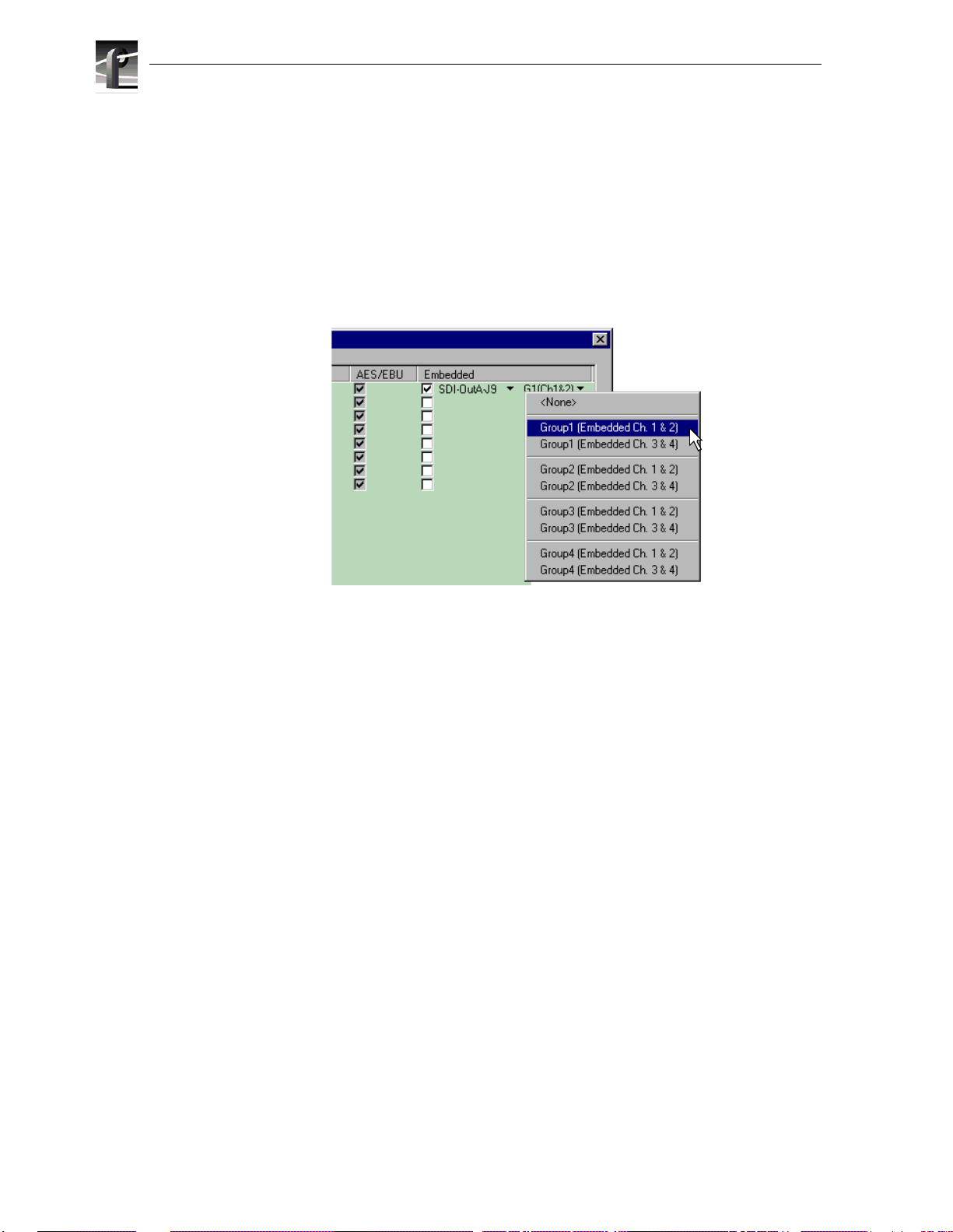
Select audio I/O format
c. Click the right-hand drop-down list arrow in the Embedded column for the
channel pair you want to configure, and select an audio group and channel pair
as shown.
NOTE: Up to two audio groups (8 audio channels ) can be embedded on a sin gle
video output. Embedded audio c an only be allocated by groups of 4 channels. In
some cases, with two audio boards installed, you may have to select embedded audio
outputs first, then select the audio inputs for each audio board to be able to select
all the desired embedded outputs.
4. Click
Finish to save your settings.
5. Continue with the next procedure in this guide to test your system setup.
38 PVS3000 & PVS3500 Installation Guide 23 February 2004
Page 39

Test your system setup using
10
161
VdrPanel
In this step, you will use VdrPanel in local control to test the record and play channels.
This procedure assumes you have video and audio signals connected to the inputs of
all record channels and have a way of monitoring the video, audio, and timecode
outputs.
In systems without record channels you must use the video network to transfer a clip
from another Profile. (See “Using Media Manager” in the
To test channels using VdrPanel:
1. Start VdrPane l using the deskt op shortcut or by select ing
Applications | VdrPanel. The VdrPanel window appears.
NOTE: The first time VdrPanel runs, a panel opens for each default record and
play channel. The number of default channels depends on your model. Refer to
“Default Video Connections” on page 5.
23 February 2004).
Start | Programs | Profi le
2. Record a short clip, a few seconds in duration as follows:
a. Click the
Size display indicates compressed frame sizes during record as timecode
advances in the Timecode display.
b. Click the
is #1.
23 February 2004 PVS3000 & PVS3500 Installation Guide 39
Record button in the panel for a record channel. Recording starts. The
Stop button to end the recording. Notice the clip name in the clip list
Page 40

Test your system setup using VdrPanel
3. Load and play a clip on each Play Channel as follows:
a. Click anywhere in the panel for a Play Channel.
b. Select
c. Select clip #1 in the clip list, then click
d. Click
VideoClip | Load Clip to open the Load Clip dialog box.
OK to load the clip.
Play and verify that video, audio are present at the channel outputs. If you
have a problem, refer to the Chapter 10, “Solving Common Setup Problems” in
the Profile XP System Guide.
4. Use steps 2 and 3 to test all record and play channels.
5. Co ntinue with the next procedure in this guide to adjust video timing.
40 PVS3000 & PVS3500 Installation Guide 23 February 2004
Page 41

11
171
Adjust video output timing
All playback channels are zero timed by default, however, video output timing
adjustment is provided to meet downstream timing requirements if needed. In this
procedure you will load a clip and verify the output timing for each play channel.
To adjust video output timing:
1. In VdrPanel, load and playback a clip as follows:
a. Click anywhere in the panel for the first Play Channel.
b. Select
c. Select a clip to load, then click
d. Click the
e. Repeat step a through step d for all Play channels.
Video Clip | Load Clip to open the Load Clip dialog box.
OK.
ee ( ) button in the panel.
23 Febuary 2004 PVS3000 & PVS3500 Installation Guide 41
Page 42

Adjust video output timing
2. Select Video Timing in the Configurati on Manager window. Page 1 of the Video
Timing dia log box app ears.
3. Click
Next to navigate to page 2 of 3.
Delay
Advance
4. Select the video output from the list, then adjust the video output timing with the
timing controls.
NOTE: Use the Select All button to enter the same offset for all video outputs.
5. Repeat step 4 for each video output.
6. Click
Finish to save your settings.
7. Continue with the next procedure in this guide to select RS-422 control protocol.
42 PVS3000 & PVS3500 Installation Guide 23 Febuary 2004
Page 43

12
181
Select an RS-422 control protocol
Profile XP Media Platform remote control protocols are shown in the table. Follow
the proced ure indi cated for the remot e contr ol protoc ol you w ant to use. If you ar e not
using RS-422 c ontrol, you can skip this st ep
Protocols Available Application to Use Procedure to Follow
Louth Protocol
Odetics Protocol
BVW Protocol
Profile Protocol Prolink Setting up RS-422 remote control using Prolink
NOTE: Some third-party applications also support the General Purpose Interface
(GPI). Refer to your vendor’s documentation for instructions on using GPI
triggers.
VdrPanel Setting up RS-422 remote control in VdrPanel
(Profile protocol)
Setting up RS-422 remote control in VdrPanel
To setup a VdrPanel for remote control:
1. If VdrPanel is not already running, start it using the desktop shortcut or by selecting
Start | Programs | Profile Applications | VdrPanel. The VdrPanel window appears.
2. In VdrPanel, click in the panel you want to set up for remote control.
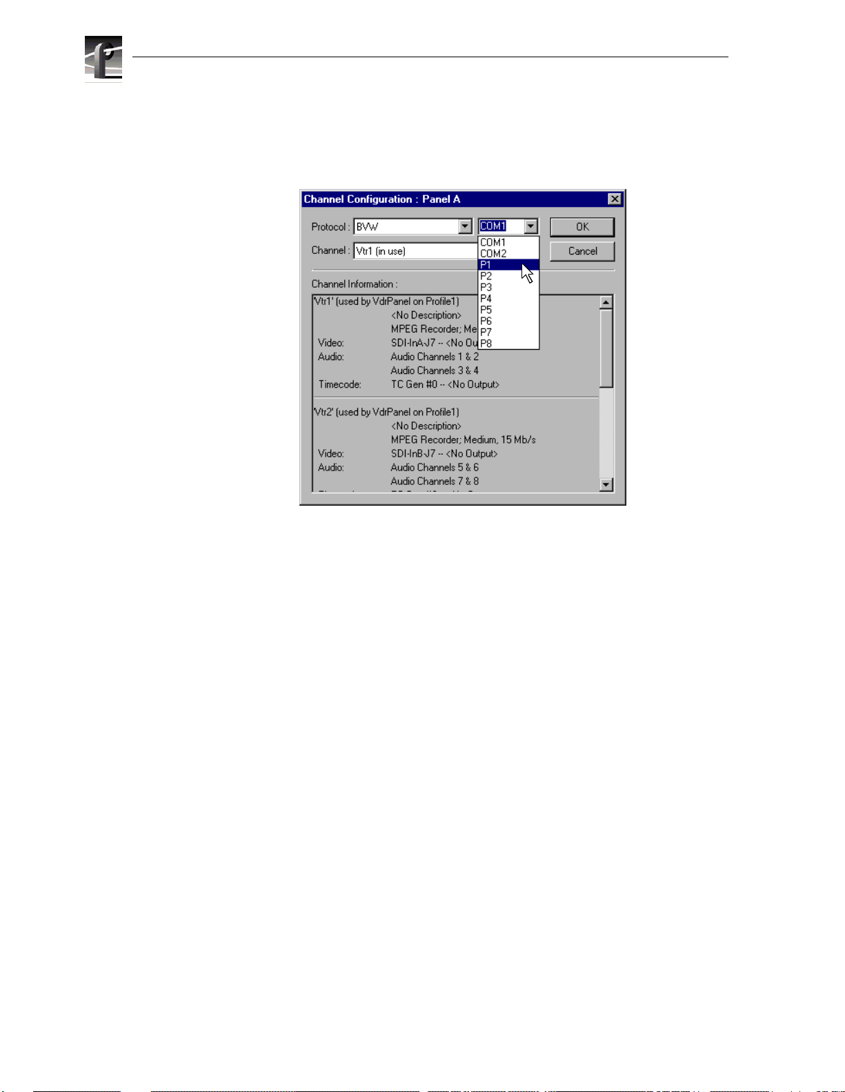
3. Choose
select a control protocol using the
Controller | Configure to open the Channel Configuration dialog box, then
Protocol drop-down l ist as shown .
23 February 2004 PVS3000 & PVS3500 Installation Guide 43
Page 44
Select an RS-422 cont rol proto col
4. Select a serial port using the port select drop-down list as shown. COM1 and COM2
are RS-232 po rt s on th e PVS3000 rear panel. P1 t h roug h P 8 ar e RS -422 por ts o n the
I/O Panel.
Figure 1. dialog box
5. Click OK in the C hannel Configuration dialog box.
6. Repeat step 2 through step 5 for the remaining panels.
7. Test the system using your automation controller.
This completes all the procedures in this Installation Guide. Refer to the Profile XP
System Guide for more information on customizing settings for your application.
44 PVS3000 & PVS3500 Installation Guide 23 February 2004
Page 45

Select an RS-422 control protocol
Setting up RS - 42 2 re m ot e control using Prolink ( P rofile protocol)
Use this procedure to start and set up Prolink to control the Profile XP Media Platform
using Profi le protocol .
1. Close VdrPanel if you used it earlier to test your record and play channels.
2. Open Prolink using the shortcut on the desktop or by selecting
Profile Applications | Prolink.
3. Select an RS-422 serial port, then click
Select. The Proli n k w ind ow a pp ea rs .
Start | Programs |
4. Test the PVS3000 system using your con t roller.
5. Repeat steps 2-4 f or the numbe r of control ports you need to control th e PVS3000
using Profile protocol.
NOTE: For more information on the Prolink user interf ace see Chapter 8,
“Controlling the Profile XP Remotely” in the Profile XP System Guide.
This completes all the procedures in this Installation Guide. Refer to the Profile XP
System Gu ide for more information on customizing settings for your application.
23 February 2004 PVS3000 & PVS3500 Installation Guide 45
Page 46

Select an RS-422 cont rol proto col
46 PVS3000 & PVS3500 Installation Guide 23 February 2004
Page 47

Grass Valley Product Support
To get technical assistance, check on the status of problems, or report new problems,
contact Grass Valley Product Support via e-mail, the Web, or by phone or fax.
Web Technical Support
To access support information on the Web, visit the product support Web page on the
Grass Valley Web site. You can download software or find solutions to p roblems by
searching our Frequently Asked Questions (FAQ) database.
World Wide Web: http://www.thomsongrassvalley.com/support/
Technical Support E-mail Address: gvgtechsupport@thomson.net
Phone Support
Use the following information to contact product support by phone during business
hours. Afterhours phone support is available for warranty and contract customers.
United States (800) 547-8949 (Toll Free) France +33 (1) 34 20 77 77
Latin America (800) 547-8949 (Toll Free) Germany +49 6155 870 606
Eastern Europe +49 6155 870 606 Greece +33 (1) 34 20 77 77
Southern Europe +33 (1) 34 20 77 77 Hong Kong +852 2531 3058
Middle East +33 (1) 34 20 77 77 Italy +39 06 8720351
Australia +61 3 9721 3737 Netherlands +31 35 6238421
Belgium +32 2 3349031 Poland +49 6155 870 606
Brazil +55 11 5509 3440 Russia +49 6155 870 606
Canada (800) 547-8949 (Toll Free) Singapore +656379 1390
China +86 106615 9450 Spain + 34 91 512 03 50
Denmark +45 45968800 Sweden +46 87680705
Dubai + 971 4 299 64 40 Switzerland +41 (1) 487 80 02
Finland +35 9 68284600 UK +44 870 903 2022
Authorized Support Representative
A local authorized support representative may be available in your country. To locate
the support representative for your country, visit the product support Web page on the
Grass Valley Web site.
Profile Users Group
You can connect with other Profile XP Media Platform users to ask questions or share
advice, tips, and hints. Send e-mail to profile -users@ thomson .net to join the community
and benef it from the experience of others.
23 February 2004 PVS3000 & PVS3500 Installation Guide 47
Page 48

48 PVS3000 & PVS3500 Installation Guide 23 February 2004
 Loading...