

Page 1

FIBRE CHANNEL SWITCH
Installation Manual
PROFILE FAMILY
VIDEO FILE SERVERS
071-0564-04
JULY 2001
Page 2

Copyright Copyright © 2001 Grass Valley Group Inc. All rights reserved. Printed in the United
States of America.
This do cument m ay not be copied i n whole o r in part , or other wise repr oduced
except as sp ec ifi ca ll y permit ted un de r U. S. copyri gh t law , wi th ou t the prior writ ten
consent of Grass Valley Group Inc., P.O. Box 59900, Nevada City, California
95959-7900
Trademarks Grass Valley, GRASS VALLEY GROUP, Profile and Profile XP are either
registe red trad em arks or trad ema rk s of Gras s Va ll ey Gr oup in the Uni ted Stat es
and/or other countries. Other trademarks used in this document are either
registered trademarks or trademarks of the manufacturers or vendors of the
associ ated pro du ct s. G rass V a lley G ro up prod uc ts ar e co ver ed by U .S. an d f or eig n
patents, issued and pending. Additional info rmation regarding
Grass Valley Grou p's tradem arks and oth er propri etary right s may be fou nd at
www.grassvalleygroup.com.
Disclaimer Product options and specifications subject to change without notice. The
informati on in this manual is furnished for informational use only , is subject to
chang e witho ut notic e, an d shou ld not b e con strued a s a com mitme nt by G rass
Valley Group. Grass Valley Group assumes no responsibility or liability for any
errors or inaccuracies that may appear in this publicatio n.
U.S. Government
Restricted Rights
Legend
Use, duplication, or disclosure by the United States Government is subject to
restrictions as set forth in s ubparagraph (c )(1)(ii) of t he Rights in Tech nical Data
and Comp ut er Sof twa re clau se at DFA RS 25 2.277 -7 013 or in su bpara gra ph c(1 )
and (2) of the Comm ercial Co mputer So ftware Re stricte d Rights cl ause at FAR
52.227-19, as applicable. Manufacturer is Grass Valley Group Inc., P.O. Box
59900, Nevada City, California 95959-7900 U.S.A.
Revision Status
Rev Date Description
February, 1999 Origin al is su e. Manual Par t Num b er 071-056 4-0 0.
September, 1999 Updated to include new switch models and Profile XP
support.
Manual Part Number 071-0564-01.
November 2000 Revised Product Support contact information.
Part Number 071-0564-02.
February 2001 Added NetCentral II support.
Part Number 071-0564-03.
July 2001 Added Media Area Network information.
Part Number 071-0564-04.
Page 3

3
Contents
Grass Valley Group Product Support........................................................................... 4
Welcome................................ ............................................................ .......................... 5
How to Use the Manuals...................................................................................... 6
Support for Your Fibre Channel Switch........................................................ ..... ... 6
Installing a Switch in a Profile Video Network. ............................................................. 7
Profile System Software Requirements................................................................ 8
Fibre Channel Firmware and Driver Requirements.............................................. 9
Loading Profile Firmware.......................................... ....... ..... .. ....... ..... ....... ... 9
Loading Fibre Channel Server Firmware. ..................................................... 10
Configuring Fibre Channel on Your Profile Systems............................................ 11
Configuring Your Fibre Channel Switch ............................................................... 12
Connecting Devices to the Switch........................................................................ 12
Cable Length s........ ...................................... ............................................. ... 12
Single-Switch Fabric..................................................................................... 12
Multi-Switch Fabric....................................................................................... 14
Monitorin g Your Swi tch with NetCentral II........................... ...................................... ... 17
SNMP Configuration............................................................................................. 18
Monitoring Status................................................................................................. 23
Troubleshooting with NetCentral II. ...................................................................... 25
Figures
1 The Profile Fibre Channel Switch..................................................... ....... ........7
2 The Update FC Microcode window.................................................................10
3 Single-switch fabric with no loops attached ....................................................13
4 A sample two-switch fabric..............................................................................15
5 A sample three-switch fabric...........................................................................16
6 A NetCentral II view of a Fibre Channel Switch..............................................17
7 A Fabric View i n a browse r........ ........................................................... ..........19
8 The Switch Management Application..............................................................20
9 The SNMP Admin tab.....................................................................................21
10 Port status.......................................................................................................23
11 Port error statistics..........................................................................................24
Page 4

4 Profile Fibre Channel Switch
Grass Valley Group Product Support
You can get technical assist ance, check on the status of problems, or report new
problems by contacting our Produc t Support Group.
Unit ed States and Canada
Monday–Friday 5:30AM–5:00PM Pa cific Time
(800) 547-8949
Europe
Monday–Friday 9:00AM–5:30PM
Asia and South America
World Wide
24-hour Emergency Hotline (530) 478-4148 (Cont rac t and warranty
customers)
Worl d Wide Web http://www.grassvalleygroup.com/support//
FTP Site ftp.grassvalleygroup.com
E-mail [email protected]
France
01 45 29 73 00
United Kingdom 01628 40583 0
Germany 49 221 1791 234 Other +44 1753 218 777
Italy 02 25086606
Australia
- from overseas
02-9888 0100
61-2-9888 0100
Japan 81-3-3448-3111
Korea 82-2-528-5299
Beijing 86-10-62351230
ext. 711
Mexico 52-5-666-6333
Singapore 65-356-3900
Brazil 55-11-3741-8422 Taiwan 886-2-27571571
Hong Kong 852-2585-6579
Page 5

Welcome
Profile Fibre Channel Switch 5
Welcome
You can use your eight- or sixteen- port Brocade Si lkWorm Fibre Channel switc h
to create fabrics for Grass Valley Group Media Area Networks (SCSI protocol)
and Profile Vi deo Ne twork s ystems (Int ernet Protocol ). Thi s man ual supp lements
the information provided by the Brocade SilkWorm manuals that you received
with your switch.
Please refer to the following Brocade manuals, included on the SilkWorm 2000
Family Documentati on CD-ROM, when i nstalli ng and c onfiguring your Broc ade
SilkWorm Fibre Channel switch.
• SilkWorm Hardware Reference Manual - This is your pr imary reference on
the installati on and init ia l setup of your sp ecific mod el of Silk Worm switch.
It also provides maintena nce and repair information.
• BROCADE WEB TOOLS User’s Guide - This manual describes the Web
browser-based applic ation that allows you to monitor and administe r your
Brocade SilkWorm switch. Open the
Table of Contents for the SilkWorm
2000 Family Documentation CD-ROM, choose
BROCADE Fabric Services
Users Guides Version 2.2
, then BROCADE WEB TOOLS 2.2.
NOTE: If you are installin g the SilkWorm switch in a Media Area Network,
please refer to your Med ia Area N etwork I nstructio n Manual for detailed
installation and configuration information.
Page 6

6 Profile Fibre Channel Switch
How to Use the Manuals
The following table descr ibes how to u se the documentation set that accom panies
your SilkWorm Fibre Channel switch and oth er Grass Valley Group products.
Support for Your Fibre Channel Swi tch
Your Brocade SilkWorm Switch is s old, supported, a nd servic ed by Grass Valle y
Group.
If you have any questions about your Broca de SilkWorm Switch, or if you need
any help or service for the switch, please contact your local Grass Valley Group
Support representa tive listed at the front of this manual
NOTE: Do not contact Brocade Communication Systems directly for support
of your Brocade SilkWorm Switch.
For information on... See...
Installing the switch in a
Profile Video Network
“Installing a Sw itch in a Prof ile Video Network” beginning on
page 7 of this manual.
SilkWorm Hardware Reference Manual
Brocade WEB TOOLS User’s Guide
Installing the switch in a
Media Area Network
Media Area Network Instruction Manual
SilkWorm Hardware Reference Manual
Brocade WEB TOOLS User’s Guide
Configuring the SilkWorm switch
for NetCentral monitoring
“Monitoring Your Switch with NetC entral II” beginning on page
17 of this manual.
SilkWorm Hardware Reference Manual
BROCADE WEB TOOLS User’s Guid e
Page 7
Installing a Switch in a Profile Video Network
Profile Fibre Channel Switch 7
Installing a Switch in a Profile Video Network
Compared to a Fibre Channel hub, the Fibre Channel switch improves the
performance of your Video Network by:
• Increasing the bandwidth between any two Fibre Channel devices by
eliminating the shared bandwidth required by a Fibre Channel Arbitrated
Loop.
• Improving the scalability of your Video Network. By managing your interswitch connections , you can inc rease the size of your network without the
shared bandwidth concerns of a large loop.
• Providing optional multicast capability, which lets you move materia l to
several machines at once, rat her than with several individual transf ers.
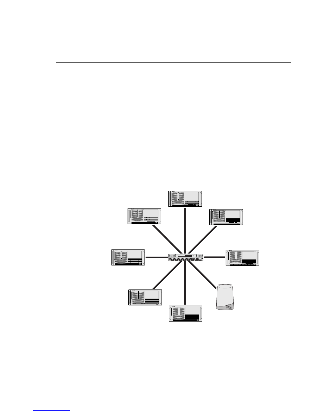
Figure 1 shows the Profile Fibre Channe l switch in a simple fabric environment.
Figure 1. The Profil e Fibr e Channel Switch
0564-1
Page 8

8 Profile Fibre Channel Switch
The sections tha t follow describe the inst allation and use of the Brocade SilkWorm
Switch in a Profile Video Network envir onment. Topics include:
• Installing the required Profile System Software version (2.5 or higher). All
versions of Profile XP System Softwa re support the Profile Fibre Channel
Switch.
• Loading the required Profile Fibre Channel firmware onto the Profile Fibre
Channel card, and ensuri ng that other Fibre Channel dev ices on the fabric are
using compatible firmware .
All versions of Prof ile XP Fibre Channel boa rds have t he requir ed firmware
for operation with the Profile Fibre Channel Switch. You do not need to
change the Fibre Channel firmware or drive rs on Profile XP systems.
• Configuring the Profile system to work with a switch (fcconfig -s on). This
step is not required on a Profile XP.
• Avoiding loop configurations in a fabric (switched) environment.
Profile System Software Requirements
You must install Profile Syste m Software version 2.5 or higher on all Profile
systems connected to a Fibre Channel switch. You must install Profile System
Software 2.5 or hi gher be fore loading t he switc h-compatibl e Fibre Chan nel boa rd
firmware.
Please refer to the Profile Release Notes for instructions on how to instal l your
Profile Syst em Sof twa re, as well as inf ormation on the new feat ures that are
included in th e releas e.
All Profile XP System Software versions fully support the Profile Fibre Channel
Switch. Be sure to read the Profile XP Release Notes to learn about any new
requirements.
Page 9

Fibre Channel Firmware and Driver Requirements
Profile Fibre Channel Switch 9
Fibre Channel Firmware and Driver Requirements
Early versions of the firmware for the Profile Fibre Channel board (1.4, 1.7.X)
supported the Fibre Channel Arbi trated Loop, but would not functi on with a Fibre
Channel switch. More recent versions of the firmware support operat ion with a
switch and inter operation wit h other Fibre C hannel board manuf acturers, b ut have
not been optimized for use in a loop.
To operate in a fabr ic environment, one which uses switches, you must use Fibr e
Channel board f irmware that is c ompatible wit h the switc h. You may use t he same
firmware in a loop environment, but you may encounter operational limita tions
that are not present with earl ier versions of the firmware.
Generally, Fib re Cha nnel fir mware versions numbere d 3.0 or h igher, o r ide ntifie d
as switch compatible, or interoperable, all support operation with the Fibre
Cha nn el sw it c h .
NOTE: All versions of Profile XP Fibre Channel boards have the required
firmware for operation with the Profile Fibre Channel Switch. You should
not perform the following procedu re on a Profile XP system.
Loading Profile Firmware
Once you have installed Profile System Software version 2.5 or higher, you can
load a switch-compatible version of firmware onto your Profile Fibre Channel
board. You must load this firmware before connecting your P rofile system to the
Brocade SilkWorm Switch . You must also use this vers ion of firmware if you wish
to connect your Profile system to any other device that is equipped with Fibre
Channel board from a supplier other than Grass Valley Group.
NOTE: Do not perform this procedure on a Profile XP system.
To load the switch-compatible firmware on your Profile Fibre Channel board:
1. Close any applications that may be running on the system.
2. At a command line, type
vdrsvc -start and the n press Enter. This starts the
PDR Access Service if it is not already started.
3. Choose
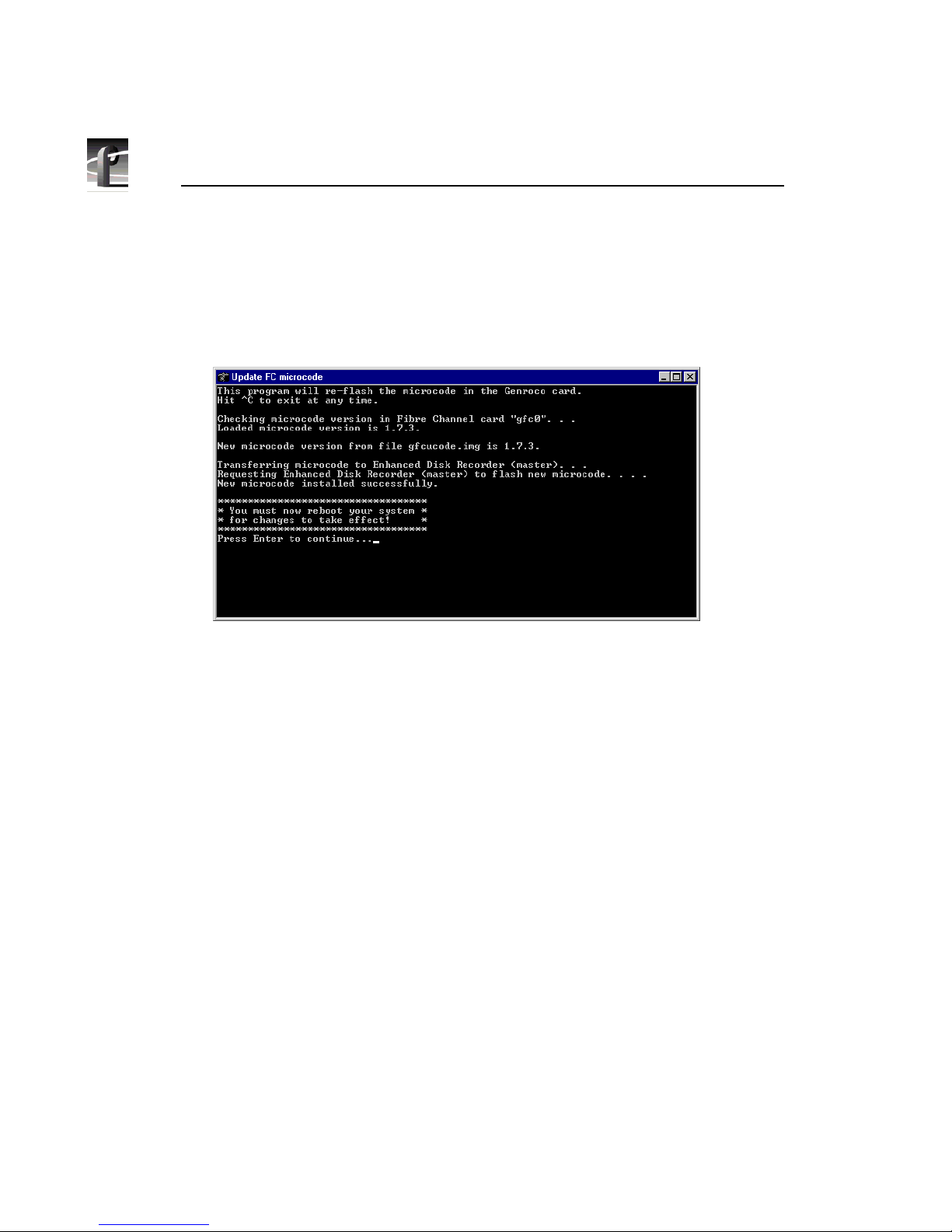
Start | Programs | PDR Debug Tools | Update FC Switch Microcode . A
window appears.
4. The program asks if you want to continue. Type
Y.
Page 10
10 Profile Fibre Channel Switch
5. The program now reads the new image of the firmware from
c:\profile\etc\sfcucode.img. The program automatically copies the old
firmware to the file c:\profile\etc\sfcucode.old.
6. Restart the disk recorder in order for the firmware update to take effect.
Figure 2. The Update FC Microcode window
Loading Fibre Channel Server Firmware
If you wish to connect a Profile Fibre Channel Server to a Brocade SilkWorm
Switch, you must load switch-compatible firmware on all the Fibre Channel
boards installed in your server. You must also install the appropriate Fibre
Channel dri vers that can use al l the feat u re s of the n ew fi rmw a re.
NOTE: A Profile Fibre Channel Server consist s of an SGI O200 or O2000
system equipped with Fibre Channel boards pur chased from Grass Valley
Group. If your Fibre Channel boards were purc hased obtained from another
source, please ask your supplier about compatibility with the Brocade
SilkWorm Switch.
To load switch-compatibl e firmware on your Fibre Channel Server boards:
1. Contact Grass Valley Group support to obta in the location of the latest
firmware, then download the files from that location.
2. Place the files in the /temp/drivers on the destination SGI server.
Page 11

Configuring Fibre Channel on Your Profile Systems
Profile Fibre Channel Switch 11
3. Follow the instructi ons in the Genrocco Fibre Channel Adapter Installation
Manual to load the firmware onto each of the Fibre Channel boards.
4. Follow the instructi ons in the Genrocco Fibre Channel Adapter Installation
Manual to install the appropriate driver on the system.
5. Reboot the SGI server.
Configuring Fibre Channel on Your Profil e Systems
Once you’ve installed the requir ed ver sion of Pr ofile System Softwar e and l oaded
the appropriate fir mware and drivers on all the devices you are connecting to the
switch, you must configure each Profile Video File Server or Profile Fibre
Channel Server for operation in a Fibre Channel fabric environment.
NOTE: Profile XP Media Platforms are pre-configu red for operation in a
fabric (switched) Fibre Channel Environment. You must not perform this
procedure on a Profile XP system.
To configure your Profile Fib re Channel server or any device other than your
Profile system, refer to the installation manual for that de vic e for instructions.
To configure your Prof ile system for use in a Fibre Channel environment, f ollow
the instructions in the Profile User Manual. In addition to these instructions, you
must also set Fib re Channel Switch Mode ON. You can do this in on e of two ways:
• Type the following command from the Command Prompt: fcconfig - s on.
OR
• In Configuration Manager, select Switch Compatibility Mode in the Fibre
Channel Configuration dia log box.
NOTE: You do not need t o set the F ibre Channel hardware addres s of Profile
systems connect ed to the Fibre Channel swit ch. These add resses are ass igned
dynamically in a fabric environ ment.
Page 12

12 Profile Fibre Channel Switch
Configuring Your Fibre Channel Switch
Your Brocade SilkWorm Switch will opera te correctly in your Fibre Channel
fabric environment using the default settings with the follo wing exce ptions:
1. You must set the domain for your site.
2. You must set Non-SCSI Tachyon Mode for use in an Internet Protocol (IP)
environment such as a Profile Vide o Network.
Refer to the SilkWorm Hardware Reference Manual for instruct ions on how to
make these settings.
Connecting Devices to the Switch
Follow the instructi ons in the SilkWorm Hardwar e Referen ce Manual t o connect
your Profile systems and other device s to the Fibre Channel switch. You should
also take note of the following guide lines when setting up your fabric
environment.
Cable Lengths
Use the appr opriate cable types and GBIC s (Gigabit Inter face Converters) for the
length of your Fibre Chan nel connections. In general, distances under 5 meters can
be connected with copper cables. Distances from 5 to 500 meters require the use
of fiber-optic cabl e.
NOTE: Profile Fibre Channel cables sold for use with Fibre Channel hubs
do not have the required connectors for use with the Fibre Channel switch.
You must obtain cables appropriate for use with the switch.
Single-Switch Fabric
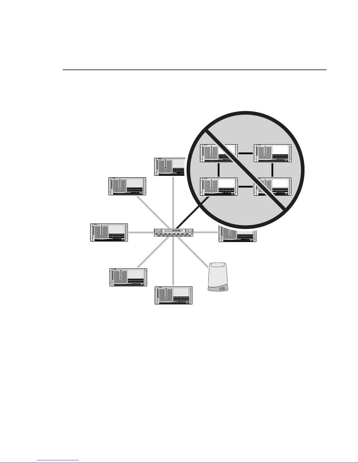
Figure 3 shows a basic Fibre Channel fabric , in whic h up to eight or sixteen
devices are connected to the switch. Each device se nds and receiv es only the data
that is specific to tha t dev ice. Ea ch device benefits from a dedi cated co nn ecti o n,
which allows for the full Fibre Channe l bandwidth to each device.
NOTE: As shown in Figure 3, you must not connect a Fibre Channel
Arbitrated Lo op to a Fibr e Channel Swi tch port. Gra ss Valley Gr oup does n ot
support loops in a fabric environment.
Page 13
Connecting Devices to the Switch
Profile Fibre Channel Switch 13
Figure 3. Single-switch fabric with no loops attached
0564-2
Fibre Channel Loop
(not supported)
Page 14

14 Profile Fibre Channel Switch
Multi-Switch Fabric
If you need to connect more than sixteen Fibre Channel devices together in your
video network, you must us e more than one swit ch to make your connecti ons. You
may interconnect up to sixteen switc hes, but you should follow some basic rules
when increasing the size of your fabric.
• You should ensure that you have at least t wo inter-switch connec tions from
each switch. This will provide:
- Redundant paths between switches.
- The ability to balance loads over several c onne ctions.
• Increasing the number of inter- switch connections will increase the
bandwidth between the switc hes, and thus between devices connected to
diff e rent s w it c hes.
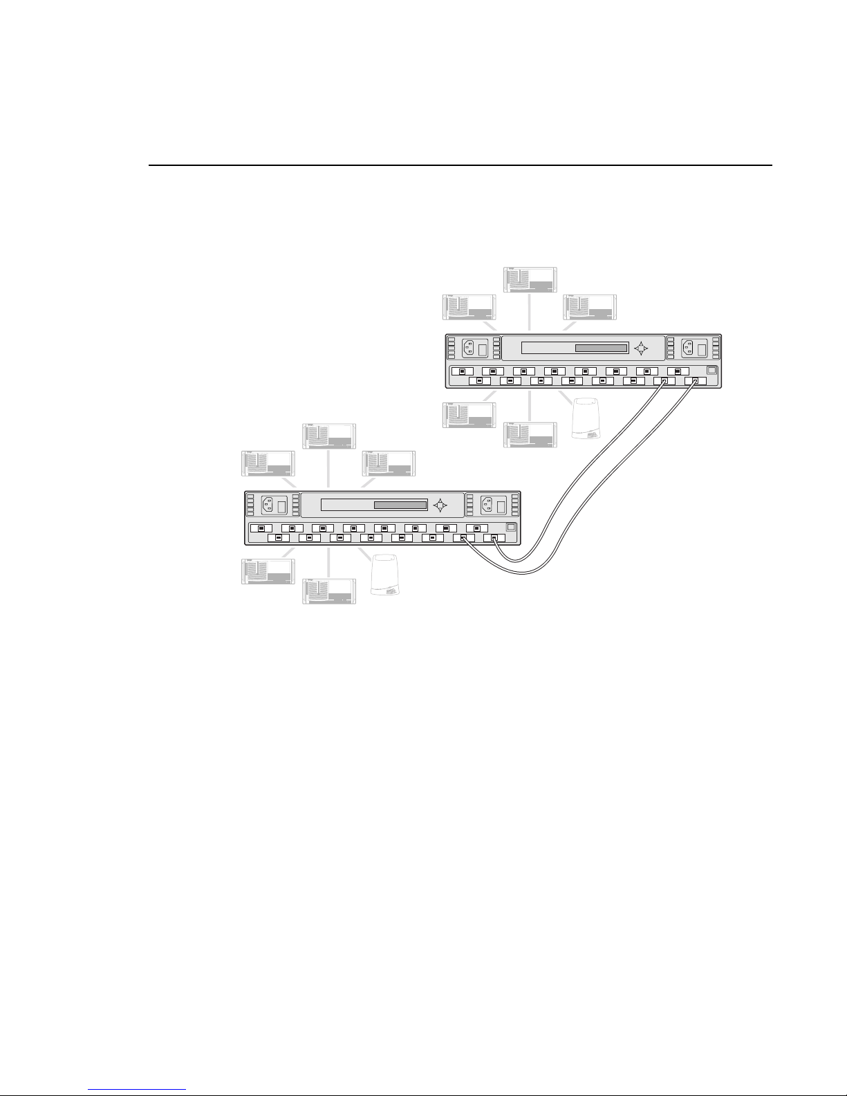
Figure 4 illustrates a fabric com prising two Fibr e Channel switches. Note the two
connections between the switches.
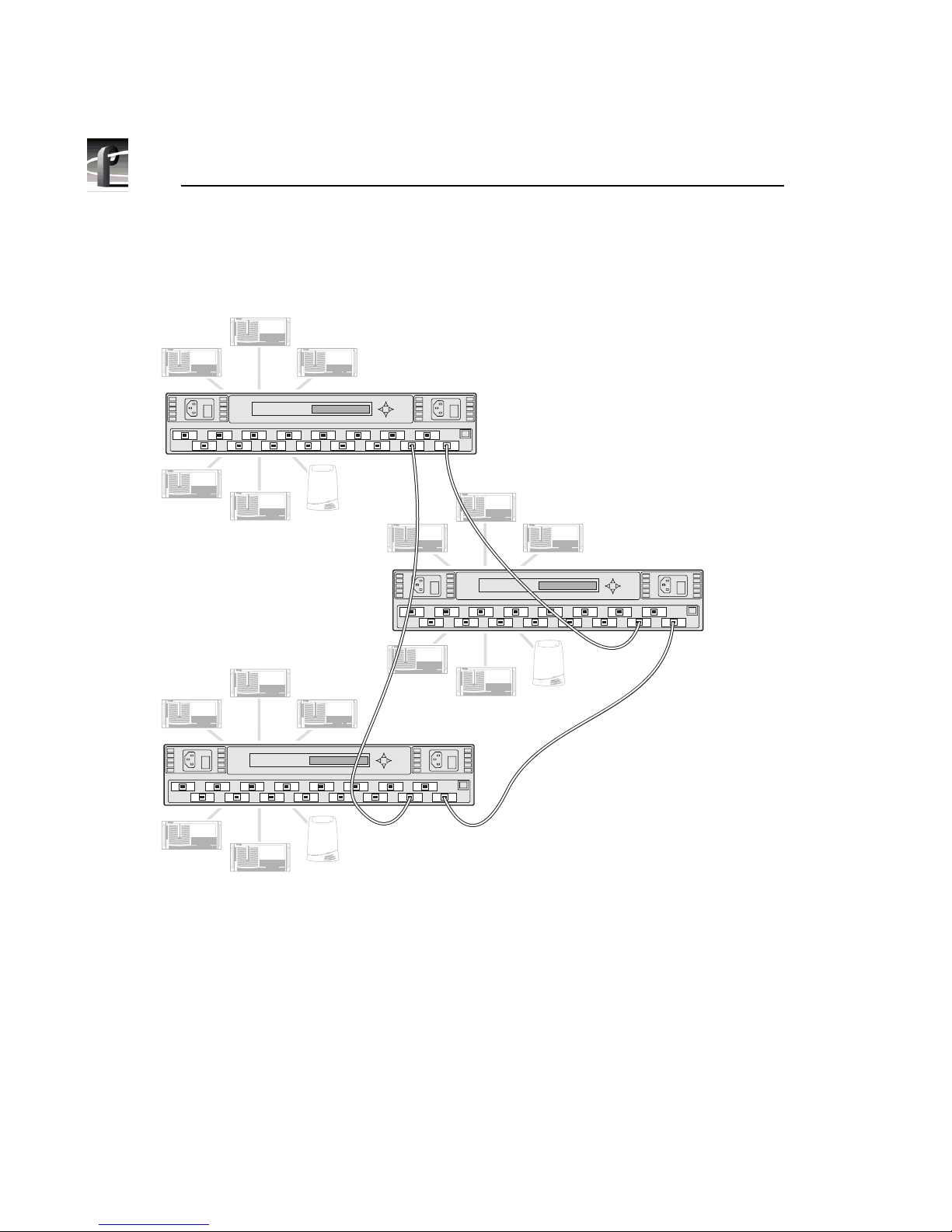
Figure 5 shows three switches conne cted together. Note that each switch is
connected to t wo other switches. You do not need two connections between each
pair of switc hes, as t he f ailure of any on e connecti on wil l still pr ovide an a lternat e
connection over another route.
Adding more inter-switch co nnections will increase the redunda ncy and
bandwidth capabil ity, but it will r educe the total number of devices which you can
connect to eac h swi tch.
Page 15
Connecting Devices to the Switch
Profile Fibre Channel Switch 15
Figure 4. A sample two-switch fabric
0564-3
Page 16
16 Profile Fibre Channel Switch
Figure 5. A sample three -switch fabric
0564-4
Page 17
Monitoring Your Switch with NetCentral II
Profile Fibre Channel Switch 17
Monitoring Your Switch with NetCentral II
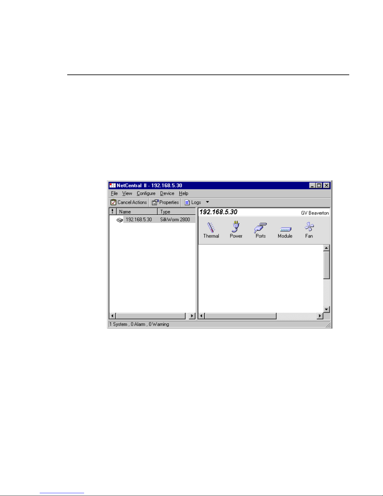
You can use NetCentral II, a Grass Valley Group SNMP Manager, to moni tor the
state of your Fibre Channel swit ch. The information presented in NetCentral II
allows you to verify the normal operation of your switch and to detect any
problems that may occur. If you set one or more appropriate SNMP trap
destination addr esses on your switch, you can also be alerted immediately when
problems occur on the switch.
Figure 6. A NetCentral II view of a Fibre Channel switch
The following sections describe how to configure your switch for operati on with
NetCentral II, and provide a brief guide on how to troubleshoot switch problems
using NetCentral II. Please refer to the NetCentral II User Guide for information
on how to install and use NetCentral II.
Page 18

18 Profile Fibre Channel Switch
SNMP Conf iguration
NetCentral II monitors the state of your Fibre Channel switch if your switch is
connected to an Ethe rnet network acc essible to the monitoring st ation. The SNMP
agent is a standard software item on all Fibre Channel switches.
In addition to the agent, you must install the SilkWorm Device Provider on the
NetCentral II monitoring station. The device provider supplie s many of the text
messages that you read in the NetCentra l II window. The device provider is
installed when you instal l the Profile XP Device Provider on the monitoring
station. Please refer to the Profile XP Agent and Device Provider installation
document for installation instructions.
In addition to the agent, you must install the SilkWorm Device Provider on the
NetCentral II monitoring station. The device provider supplie s many of the text
messages that you read in the NetCentral II window. Install the d evice provider on
the NetCentral II Monitoring sta tion usin g the appropria te installat ion instruc tions
shown in the table.
You should re fer to t he SilkWorm Hardware Reference Manual for instructions on
connecting your Fibre Channe l Switch to an Ethernet network and assigning an
Ethernet Internet Protocol (IP) address to your Fibre Channel switc h.
SNMP includes a mechanism to report events as soon as they occur, rather than
waiting until a device is polle d to obtain its status. This type of notification is
called a trap, and can be sent to one or several monitoring stations.
To configure the destination for trap notifications, follow these steps.
1. Configure your Fibre Channel fo r operation on an Ethernet network. Refer
to the SilkWorm Hardware Reference Manual fo r instructions on how to use
the serial port to set the Fibre Channel switch IP address on the Ethernet
network.
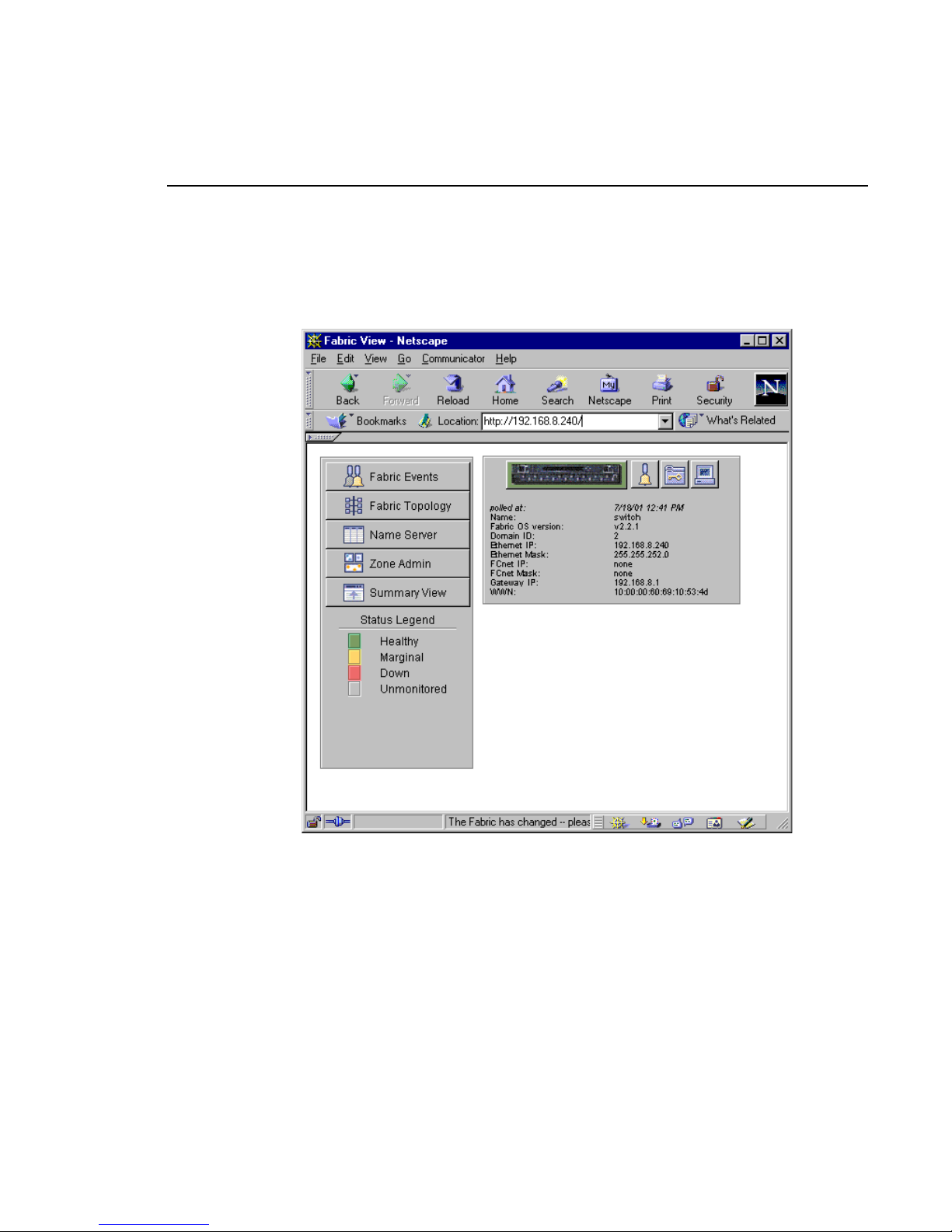
2. Use a Web browser t o launch the Brocade WEB TOOLS appl ication on the
switch by entering switch’s Ethe rnet IP address or network name in the
Fibre Channel switch application To install the SilkWorm device provider on the
NetCentral II monitoring station, see...
Profile Video Network switch fabri c Install ing the NetC entral II Agent and Device
Provi de r fo r th e Pro f ile XP Med ia Pl a tfo rm
Media Area Network switch fabric Media Area Network Instruction Manual
Page 19
SNMP Configuration
Profile Fibre Channel Switch 19
Location: line of your browser. For example, type 192.168.8.240 in your
browser to open a view of that switch and its fabric.
Figure 7. A Fabric View in a browser
Page 20
20 Profile Fibre Channel Switch
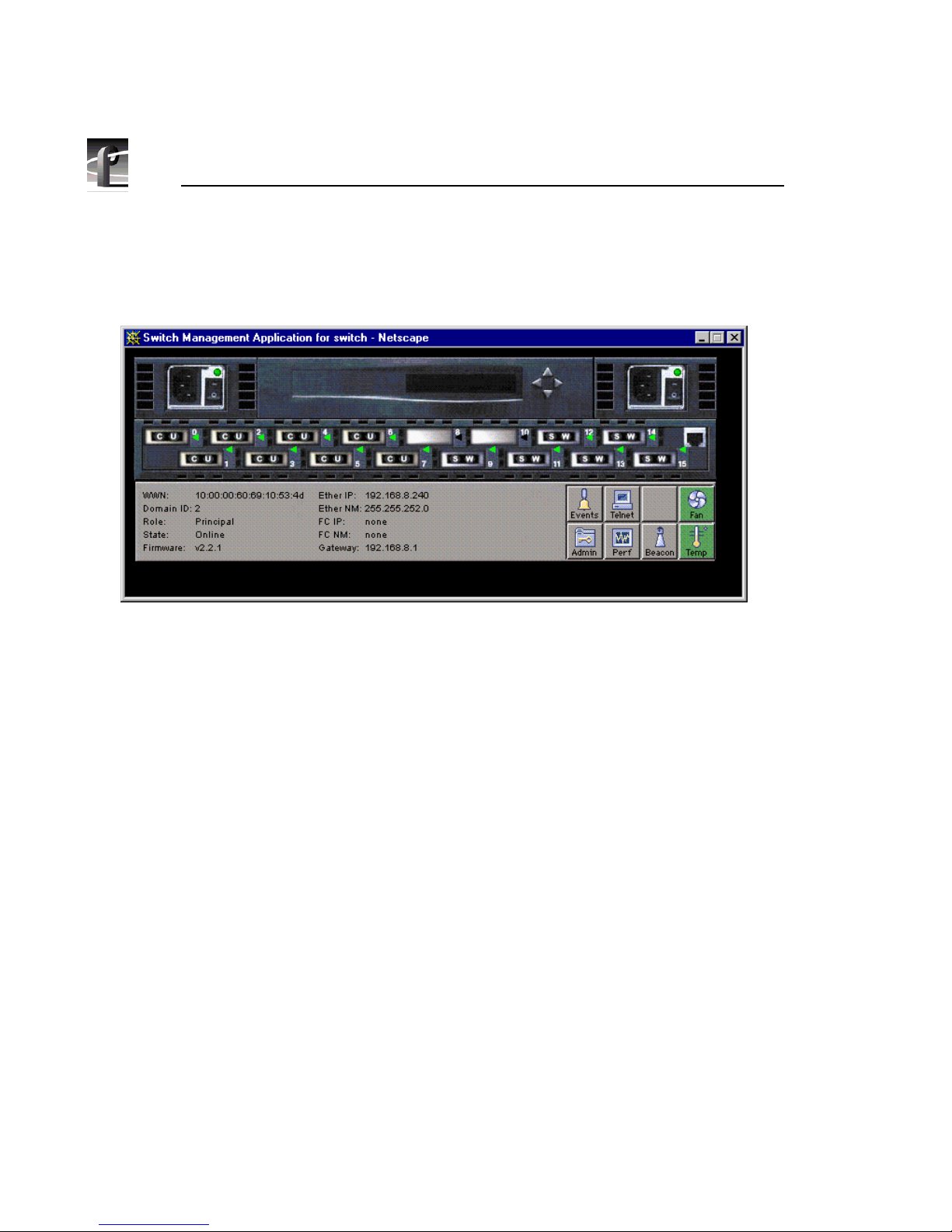
3. In the Fabric Vi ew, clic k the image of the swi tch tha t you wi sh to config ure.
This opens a switch management application for that switch.
Figure 8. The Switch Management Application
4. Click the Admin button and log in as user admin. Refer to the BROCADE
WEB TOOLS User’s Guide for information on passwords.
Page 21
SNMP Configuration
Profile Fibre Channel Switch 21
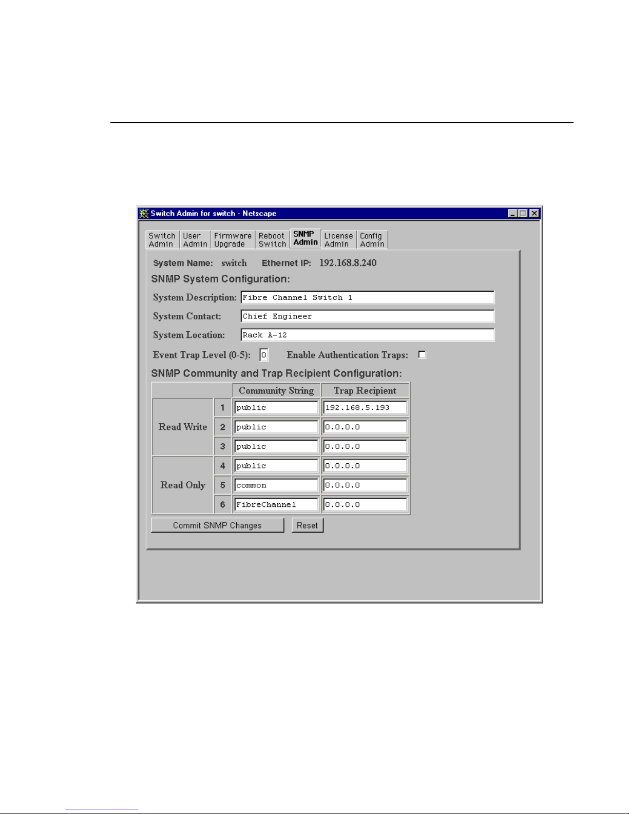
5. In the Switch Admin page, choose the SNMP Admin tab.
Figure 9. The SNMP Admin tab
6. In the SNMP Admin tab, enter meaningful System Description, System
Contact, and System Location information. This informati on is repor ted
through NetCentral II.
Page 22

22 Profile Fibre Channel Switch
7. Set the Event Trap Level to 0, and do not enable Authentica tion Traps.
8. Enter public as either a Read Write or Read Only Community S tring. For
that entry, set the IP address of your NetCentral II monitoring station.
9. Repeat the preceding step for all other NetCentral II monitoring stations.
10. Once you have made all of your SNMP settings, press the
Commit SNMP
Changes
button.
Your monitoring statio n should now receive all traps from your Fibre Channel
switch. You can test this by creating a fault condition, such as disconnecting one
of your Fibre Channe l connection s to the Fibre Channel switch. A message should
appear in the NetCentral II manager.
Page 23
Monitoring Status
Profile Fibre Channel Switch 23
Monitoring Status
You can use NetCentral II to monitor the status of your Brocade SilkWorm
Switch. NetCentral II displays information about the switch’s power supplies,
temperature, and fans. Cl ic k on the appropriate subsystem icon in the
NetCentral II window to view its status. Consult the NetCentral II User Guide for
more information on using NetCent ral II.
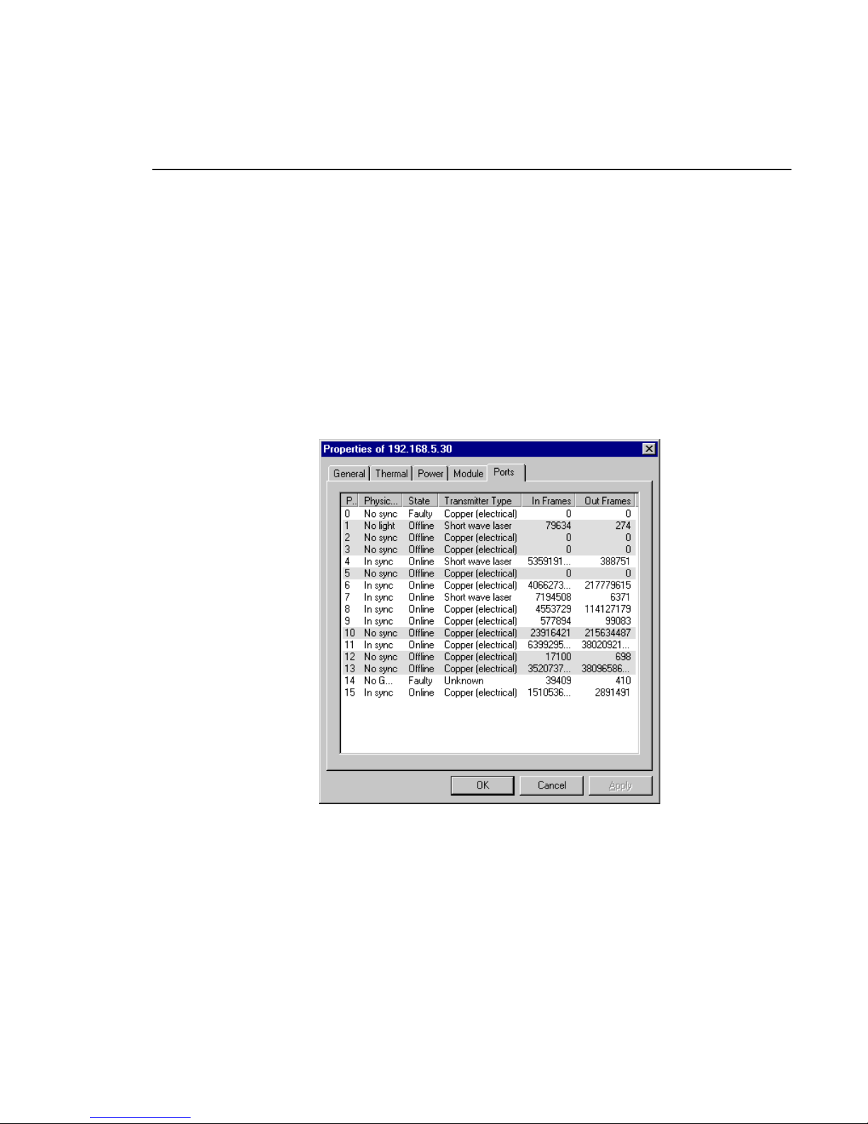
NetCentral II also lets you monitor the statu s of e ach of t he ports on you r Broc ade
SilkWorm Switch. Click the
Ports icon to view inform ation suc h as the stat e,
transmitter type, the number of frames in and out of each port.
Figure 10. Port status
Page 24
24 Profile Fibre Channel Switch
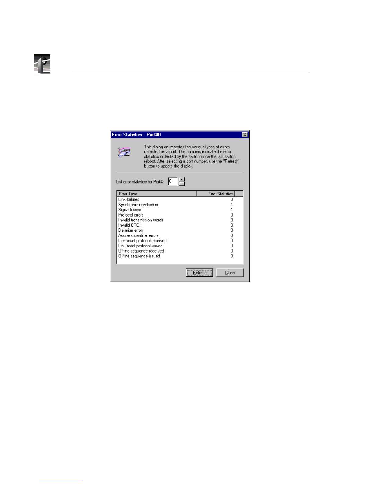
You can also view error statistics for eac h of the ports. Choose View | Port St atistics
to see a summary of the errors since the last switch reboot.
Figure 11. Port error statistics
Page 25

Troubleshooting with NetCentral II
Profile Fibre Channel Switch 25
Troubleshooting with NetCentral II
NetCentral II reports status, warnings, and a larms using messages that are easy to
understand. Suggested corrective actions are pres ented along with failure
information. The following table lists some of the possible message s, a long with
possible causes for the pro blems and ways you can repair the problems
Problem Possible Causes Corrective Action
[name] has failed. AC supply or power supply
failure.
• Verify lin e vo lta g e
• Repla ce powe r s u pp ly
System temperature exceeds
maximum recommended at
[number] C.
• Cooling air flow blocked.
• High ambient
temperature.
• Compo n ent failure.
• Remove blockage in
cooling air flow.
• Reduce ambient air
temperature.
• Run switch diagnostics.
Temperature fault at [number] C. Temperat ure sensor failed. Contact Support.
Faulty cooling fan “[name]”. Fan failed. Replace fan.
An embedded port fault was
detect ed by the Power-O n Self
Tests. T he sw it ch is not
operational.
Switch failure. Contact Support.
A central memory fault was
detect ed by the Power-O n Self
Tests. T he sw it ch is not
operational.
Switch failure. Contact Support.
Port #[n umber] is fa ul ty. • Faulty connection
• Failed GBIC
Check all cable connections at
both ends.
Replace GBIC.
Page 26

26 Profile Fibre Channel Switch
 Loading...