

Page 1

MINI MASTER CONTROL PANEL
M-2100 DIGITAL MASTER CONTROL SYSTEM
Installation and Operation
071812900
5.0software release
FIRST PRINTING: JULY 2001
Page 2
Contacting Grass Valley Group
Region Voice Fax Address Web Site
North America (800) 547-8949
530-478-4148
Pacific Operations +852-2585-6688
Support: 852-2585-6579
U.K., Europe, Asia, Middle East +44 1753 218 777 +44 1753 218 757
France +33 1 45 29 73 00
Germany +49 221 1791 234 +49 221 1791 235
Copyright © Grass Valley Group. All rights reserved.
This document may not be copied, in whole or in part, or otherwise reproduced, except as specifically
permitted under U.S. copyright law, without the prior written consent of Grass Valley Group, P.O. Box
599000, Nevada City, CA 95959-7900 USA. GRASS VALLEY GROUP is a registered trademark and
Grass Valley is a trademark of Grass Valley Group. All registered trademarks and trademarks are property of their respective holders. Grass Valley Group products are covered by U.S. and foreign patents,
issued and pending. Product options and specifications subject to change without notice. The information in this manual is furnished for informational use only, is subject to change without notice, and
should not be construed as a commitment by Grass Valley Group. Grass Valley Group assumes no responsibility or liability for any errors or inaccuracies that may appear in this publication.
Online User Documentation
(530) 478-3347 Grass Valley Group
+852-2802-2996
P.O. Box 599000
Nevada City, CA 95959-7900
USA
www.grassvalleygroup.com
Current versions of product catalogs, brochures, data sheets, ordering
guides, planning guides, manuals, and release notes may be downloaded
via the Product Documentation link on the Grass Valley Group home page:
FAQ Database
Many solutions to problems and troubleshooting efforts can be found by
searching our Frequently Asked Questions (FAQ) database. To access:
Select the Service/Support link on the Grass Valley Group home page.
1.
Select the Online Support & FAQ link on the Service/Support page.
2.
Follow the directions provided to access the FAQ database and other
3.
online support services.
Software Downloads
Software updates, drivers and patches may be downloaded via the
Download link on the Grass Valley Group home page:
Page 3

Contents
Preface
About This Manual . . . . . . . . . . . . . . . . . . . . . . . . . . . . . . . . . . . . . . . . . . . . . . . . . . . . vii
Documentation Set . . . . . . . . . . . . . . . . . . . . . . . . . . . . . . . . . . . . . . . . . . . . . . . . . . vii
Other Documentation . . . . . . . . . . . . . . . . . . . . . . . . . . . . . . . . . . . . . . . . . . . . . . . . vii
Section 1 — Installation
Introduction . . . . . . . . . . . . . . . . . . . . . . . . . . . . . . . . . . . . . . . . . . . . . . . . . . . . . . . . . 1-1
Control Panel Installation . . . . . . . . . . . . . . . . . . . . . . . . . . . . . . . . . . . . . . . . . . . . . 1-2
Control Panel Dimensions . . . . . . . . . . . . . . . . . . . . . . . . . . . . . . . . . . . . . . . . . . . 1-2
Tabletop Mounting . . . . . . . . . . . . . . . . . . . . . . . . . . . . . . . . . . . . . . . . . . . . . . . . . 1-3
Console Mounting . . . . . . . . . . . . . . . . . . . . . . . . . . . . . . . . . . . . . . . . . . . . . . . . . . 1-4
Rack Mounting. . . . . . . . . . . . . . . . . . . . . . . . . . . . . . . . . . . . . . . . . . . . . . . . . . . . . 1-5
Control Panel Cabling . . . . . . . . . . . . . . . . . . . . . . . . . . . . . . . . . . . . . . . . . . . . . . . . 1-6
Powering On. . . . . . . . . . . . . . . . . . . . . . . . . . . . . . . . . . . . . . . . . . . . . . . . . . . . . . . 1-6
Power Supply Alarms. . . . . . . . . . . . . . . . . . . . . . . . . . . . . . . . . . . . . . . . . . . . . . . 1-7
Network Configuration . . . . . . . . . . . . . . . . . . . . . . . . . . . . . . . . . . . . . . . . . . . . . 1-8
Setting MCP Net IP Address . . . . . . . . . . . . . . . . . . . . . . . . . . . . . . . . . . . . . . . 1-8
Control Panel Configuration . . . . . . . . . . . . . . . . . . . . . . . . . . . . . . . . . . . . . . . . 1-12
Control Panel Diagnostics . . . . . . . . . . . . . . . . . . . . . . . . . . . . . . . . . . . . . . . . . . 1-14
Software Installation. . . . . . . . . . . . . . . . . . . . . . . . . . . . . . . . . . . . . . . . . . . . . . . . . 1-16
System Configuration. . . . . . . . . . . . . . . . . . . . . . . . . . . . . . . . . . . . . . . . . . . . . . . . 1-16
Section 2 — System Operations
About this Section . . . . . . . . . . . . . . . . . . . . . . . . . . . . . . . . . . . . . . . . . . . . . . . . . . . . 2-1
Introduction . . . . . . . . . . . . . . . . . . . . . . . . . . . . . . . . . . . . . . . . . . . . . . . . . . . . . . . . . 2-2
Using Multichannel Control . . . . . . . . . . . . . . . . . . . . . . . . . . . . . . . . . . . . . . . . . . . 2-3
Channel Control Overview . . . . . . . . . . . . . . . . . . . . . . . . . . . . . . . . . . . . . . . . . . 2-3
Assigning Channels to Channel Control Buttons. . . . . . . . . . . . . . . . . . . . . . . . 2-4
Assigning Primaries and Secondaries. . . . . . . . . . . . . . . . . . . . . . . . . . . . . . . . 2-6
Automation Enable . . . . . . . . . . . . . . . . . . . . . . . . . . . . . . . . . . . . . . . . . . . . . . . . . 2-7
Program and Preset Bus Operations . . . . . . . . . . . . . . . . . . . . . . . . . . . . . . . . . . . . 2-8
Preset Bus . . . . . . . . . . . . . . . . . . . . . . . . . . . . . . . . . . . . . . . . . . . . . . . . . . . . . . . . . 2-8
Selecting Preset Sources . . . . . . . . . . . . . . . . . . . . . . . . . . . . . . . . . . . . . . . . . . . 2-8
Backup Preset Sources. . . . . . . . . . . . . . . . . . . . . . . . . . . . . . . . . . . . . . . . . . . . . 2-9
Program Bus. . . . . . . . . . . . . . . . . . . . . . . . . . . . . . . . . . . . . . . . . . . . . . . . . . . . . . . 2-9
Source Names Display . . . . . . . . . . . . . . . . . . . . . . . . . . . . . . . . . . . . . . . . . . . . . 2-10
Non-Sync Source Indicators. . . . . . . . . . . . . . . . . . . . . . . . . . . . . . . . . . . . . . . . . 2-11
Transition Controls and Operation . . . . . . . . . . . . . . . . . . . . . . . . . . . . . . . . . . . . 2-12
MMCP Installation/Operation Manual iii
Page 4

Contents
Transition Type . . . . . . . . . . . . . . . . . . . . . . . . . . . . . . . . . . . . . . . . . . . . . . . . . . . . 2-12
Transition Rates. . . . . . . . . . . . . . . . . . . . . . . . . . . . . . . . . . . . . . . . . . . . . . . . . . . . 2-13
Hot Switching (Hot Program Cuts) . . . . . . . . . . . . . . . . . . . . . . . . . . . . . . . . . . . 2-13
Custom Transitions. . . . . . . . . . . . . . . . . . . . . . . . . . . . . . . . . . . . . . . . . . . . . . . . . 2-14
Using Custom Transitions . . . . . . . . . . . . . . . . . . . . . . . . . . . . . . . . . . . . . . . . . 2-15
Audio/Video Breakaways. . . . . . . . . . . . . . . . . . . . . . . . . . . . . . . . . . . . . . . . . . . 2-17
Breakaway Selection Examples. . . . . . . . . . . . . . . . . . . . . . . . . . . . . . . . . . . . . 2-18
Next Transition Buttons. . . . . . . . . . . . . . . . . . . . . . . . . . . . . . . . . . . . . . . . . . . . . 2-19
Preroll Transitions. . . . . . . . . . . . . . . . . . . . . . . . . . . . . . . . . . . . . . . . . . . . . . . . . . 2-20
First Press Transitions. . . . . . . . . . . . . . . . . . . . . . . . . . . . . . . . . . . . . . . . . . . . . 2-20
Second Press (and Subsequent) Transitions . . . . . . . . . . . . . . . . . . . . . . . . . . 2-21
Hold Transitions . . . . . . . . . . . . . . . . . . . . . . . . . . . . . . . . . . . . . . . . . . . . . . . . . 2-21
Preroll Transitions Summary. . . . . . . . . . . . . . . . . . . . . . . . . . . . . . . . . . . . . . . 2-21
GPI Buttons . . . . . . . . . . . . . . . . . . . . . . . . . . . . . . . . . . . . . . . . . . . . . . . . . . . . . . . . . 2-22
Mode/Function Button . . . . . . . . . . . . . . . . . . . . . . . . . . . . . . . . . . . . . . . . . . . . . . . 2-23
Keyer Controls and Operation . . . . . . . . . . . . . . . . . . . . . . . . . . . . . . . . . . . . . . . . . 2-24
Keying Overview . . . . . . . . . . . . . . . . . . . . . . . . . . . . . . . . . . . . . . . . . . . . . . . . . . 2-24
SD Systems . . . . . . . . . . . . . . . . . . . . . . . . . . . . . . . . . . . . . . . . . . . . . . . . . . . . . . 2-25
HD Systems . . . . . . . . . . . . . . . . . . . . . . . . . . . . . . . . . . . . . . . . . . . . . . . . . . . . . 2-25
Selecting and Transitioning Keys . . . . . . . . . . . . . . . . . . . . . . . . . . . . . . . . . . . . . 2-26
Cutting Keys On or Off Air . . . . . . . . . . . . . . . . . . . . . . . . . . . . . . . . . . . . . . . . 2-26
Previewing the Key. . . . . . . . . . . . . . . . . . . . . . . . . . . . . . . . . . . . . . . . . . . . . . . 2-27
Non-Synchronous Key . . . . . . . . . . . . . . . . . . . . . . . . . . . . . . . . . . . . . . . . . . . . 2-27
Modifying Keys. . . . . . . . . . . . . . . . . . . . . . . . . . . . . . . . . . . . . . . . . . . . . . . . . . . . 2-27
Key Modifier Mode Definition . . . . . . . . . . . . . . . . . . . . . . . . . . . . . . . . . . . . . 2-28
Matte Button. . . . . . . . . . . . . . . . . . . . . . . . . . . . . . . . . . . . . . . . . . . . . . . . . . . . . 2-28
Border (Brdr) Button. . . . . . . . . . . . . . . . . . . . . . . . . . . . . . . . . . . . . . . . . . . . . . 2-30
SELF/EXT and LIN/LUM Buttons . . . . . . . . . . . . . . . . . . . . . . . . . . . . . . . . . 2-30
Key Modifier Button Tally Summary. . . . . . . . . . . . . . . . . . . . . . . . . . . . . . . . 2-31
Key Modifier Knobs . . . . . . . . . . . . . . . . . . . . . . . . . . . . . . . . . . . . . . . . . . . . . . 2-31
Recalling and Initializing Key Parameters . . . . . . . . . . . . . . . . . . . . . . . . . . . . . 2-31
Key Recall . . . . . . . . . . . . . . . . . . . . . . . . . . . . . . . . . . . . . . . . . . . . . . . . . . . . . . . 2-31
Keyer Defaults . . . . . . . . . . . . . . . . . . . . . . . . . . . . . . . . . . . . . . . . . . . . . . . . . . . 2-31
Linear/Luminance Key Unity Clip and Gain Default. . . . . . . . . . . . . . . . . . 2-32
Reset Key Parameters . . . . . . . . . . . . . . . . . . . . . . . . . . . . . . . . . . . . . . . . . . . . . 2-32
Setting Matte Configurations . . . . . . . . . . . . . . . . . . . . . . . . . . . . . . . . . . . . . . . . 2-33
Configuring Matte Crosspoints. . . . . . . . . . . . . . . . . . . . . . . . . . . . . . . . . . . . . 2-33
Configuring the Transition Matte. . . . . . . . . . . . . . . . . . . . . . . . . . . . . . . . . . . 2-33
Configuring the Loss Of Signal (LOS) Matte . . . . . . . . . . . . . . . . . . . . . . . . . 2-34
Using SqueezeBack and Crop . . . . . . . . . . . . . . . . . . . . . . . . . . . . . . . . . . . . . . . . 2-35
Defining SqueezeBack and Crop Effects . . . . . . . . . . . . . . . . . . . . . . . . . . . . . 2-35
Viewing the Current SqueezeBack Effect . . . . . . . . . . . . . . . . . . . . . . . . . . . . 2-36
Selecting and Displaying SqueezeBack Effects. . . . . . . . . . . . . . . . . . . . . . . . 2-37
Making SqueezeBack Transitions . . . . . . . . . . . . . . . . . . . . . . . . . . . . . . . . . . . 2-37
Creating Chroma Keys. . . . . . . . . . . . . . . . . . . . . . . . . . . . . . . . . . . . . . . . . . . . . . 2-38
Chroma Key Adjustments . . . . . . . . . . . . . . . . . . . . . . . . . . . . . . . . . . . . . . . . . 2-38
Auto Setup Mode . . . . . . . . . . . . . . . . . . . . . . . . . . . . . . . . . . . . . . . . . . . . . . . . 2-39
Using Auto Setup . . . . . . . . . . . . . . . . . . . . . . . . . . . . . . . . . . . . . . . . . . . . . . . . 2-40
Audio Controls and Operation. . . . . . . . . . . . . . . . . . . . . . . . . . . . . . . . . . . . . . . . . 2-41
Audio Control Subpanel . . . . . . . . . . . . . . . . . . . . . . . . . . . . . . . . . . . . . . . . . . . . 2-41
Audio Processor Delegation . . . . . . . . . . . . . . . . . . . . . . . . . . . . . . . . . . . . . . . 2-42
Audio Only PST Buttons . . . . . . . . . . . . . . . . . . . . . . . . . . . . . . . . . . . . . . . . . . 2-43
Audio Only PGM Buttons . . . . . . . . . . . . . . . . . . . . . . . . . . . . . . . . . . . . . . . . . 2-44
iv MMCP Installation/Operation Manual
Page 5

Contents
Audio Breakaway Audio (ABA) Control . . . . . . . . . . . . . . . . . . . . . . . . . . . . 2-44
Left and Right (Audio) Buttons . . . . . . . . . . . . . . . . . . . . . . . . . . . . . . . . . . . . 2-46
Stereo, L-Mono and R-Mono Modes. . . . . . . . . . . . . . . . . . . . . . . . . . . . . . . . 2-46
Phase Inversion . . . . . . . . . . . . . . . . . . . . . . . . . . . . . . . . . . . . . . . . . . . . . . . . . 2-46
PGM Level and PST Level Controls . . . . . . . . . . . . . . . . . . . . . . . . . . . . . . . . 2-47
Audio Ratio Control . . . . . . . . . . . . . . . . . . . . . . . . . . . . . . . . . . . . . . . . . . . . . 2-48
Audio Ratio Profiles . . . . . . . . . . . . . . . . . . . . . . . . . . . . . . . . . . . . . . . . . . . . . 2-50
Audio Monitor Subpanel . . . . . . . . . . . . . . . . . . . . . . . . . . . . . . . . . . . . . . . . . . . 2-54
PST, PGM, and AIR Buttons. . . . . . . . . . . . . . . . . . . . . . . . . . . . . . . . . . . . . . . 2-54
Monitor Volume Control . . . . . . . . . . . . . . . . . . . . . . . . . . . . . . . . . . . . . . . . . 2-54
DIM Buttons . . . . . . . . . . . . . . . . . . . . . . . . . . . . . . . . . . . . . . . . . . . . . . . . . . . . 2-55
Index
MMCP Installation/Operation Manual v
Page 6

Contents
vi MMCP Installation/Operation Manual
Page 7

Preface
About This Manual
This manual provides control panel installation and operating information
for the Grass Valley Group M–2100 Mini Master Control Panel (MMCP) for
use with the M–2100 Digital Master Control system. This manual is
designed for personnel responsible for installing or operating MMCP systems.
Documentation Set
The standard M–2100 user documentation set consists of a:
■
User Manual,
■
Installation and Service Manual, and
■
Release Notes.
The User Manual contains background information about the M–2100, and
describes operating procedures. This manual can be used while learning
about the M–2100, and for enhancing your basic knowledge of the system.
The
Installation and Service Manual
configuring, and maintaining the system.
The
Release Notes
enhancements for a specific software version, and also includes software
installation procedures. Always check the release notes for your current
system software before operating your system.
Other Documentation
A separate Automation Interface Protocol Technical Reference Manual is also
available for installation and operation of an external device to control the
M–2100.
contains information about installing,
contain information about new features and system
MMCP Installation/Operation Manual vii
Page 8

Preface
viii MMCP Installation/Operation Manual
Page 9
Channel Control
Transition Rate
Mode
Slow Med Fast
Keyer Control
Mon
Lvl
PreRoll
Transition
BKGD KEY
Next Transition
Audio Monitor
Mode
Func
PGM
PST DIM
AIR
Hue
Clip
Sat
Gain
Bright
Opacity
Key 1
On/Off
Brdr
Key 2
On/off
Key 3
On/off
Key 4
On/off
PGM
PST
Ratio
PGM Level
PST Level
Left Right
Left Right
AP2 AP3 AP4
1
Primary
Over
PROGSRC1
PROGSRC3 PROGSRC5
PROGSRC7
PROGSRC2 PROGSRC4
PROGSRC6
PROGSRC8
2 3 4 5 6 7 8 1 2
1 2
V
A
V
A
User
GP1 GP2
Video
Only
Audio
Only
Non Sync
Non Sync
MINI MASTER CONTROL
Audio
Video
Transition
VIDEO
Matte
SELF
EXT
Lin
Lum
SQB
Ch 1
Ch 5
Ch 2
Ch 6 Ch 7 Ch 8
Ch 3 Ch 4
12345678
8129_01
Installation
Introduction
This section gives installation and configuration instructions for the Grass
Valley Group M–2100 Mini Master Control Panel (MMCP).
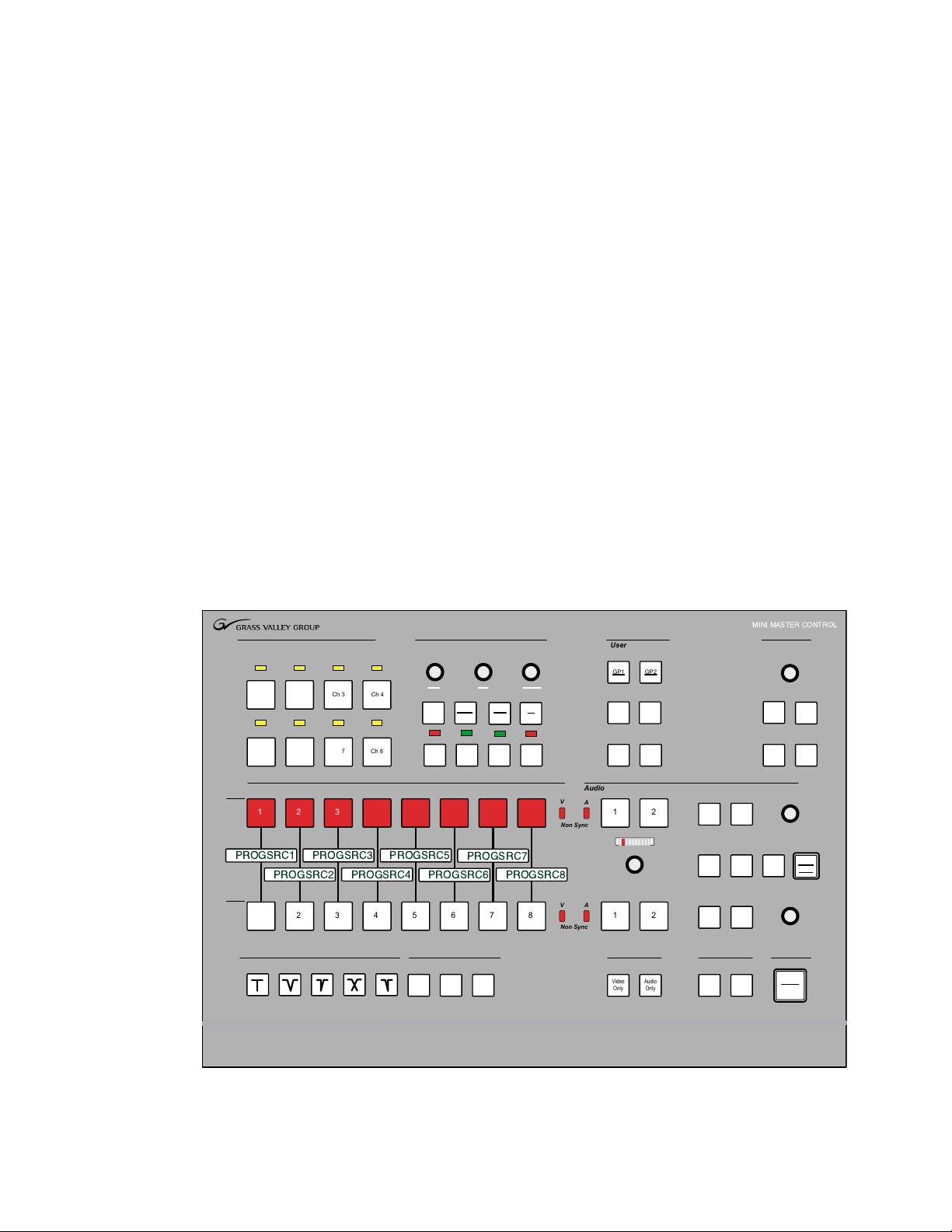
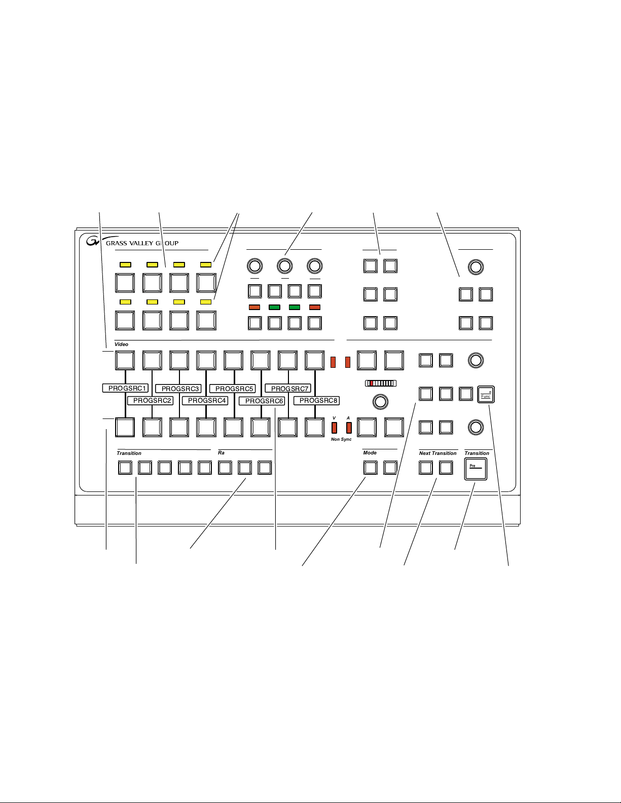
The MMCP (Figure 1-1) is a compact panel for controlling the M–2100
Digital Master Control system. It offers control of up to eight channels from
the panel, plus transition, key and audio functionality.
Note
Figure 1-1. Mini Master Control Panel
The M–2100 must be running v5.0 or later software for MMCP functionality.
Section
1
MMCP Installation/Operation Manual 1-1
Page 10
Section 1 — Installation
Control Panel Installation
The MMCP Control Panel can be installed in the following ways:
■
Tabletop mounting (page 1-3),
■
Console mounting (page 1-4), or
■
Rack mounting (page 1-5).
The kit for rack and console mounting is a separate option.
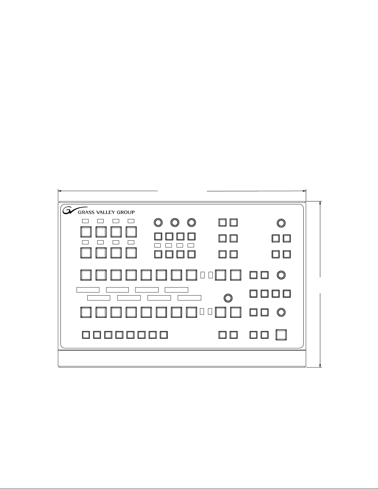
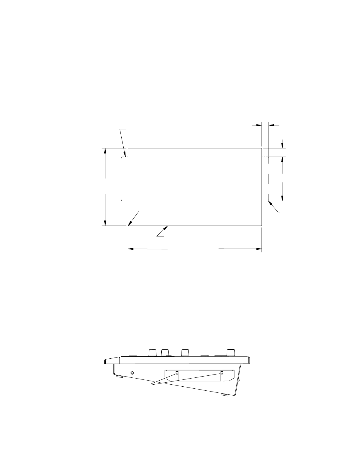
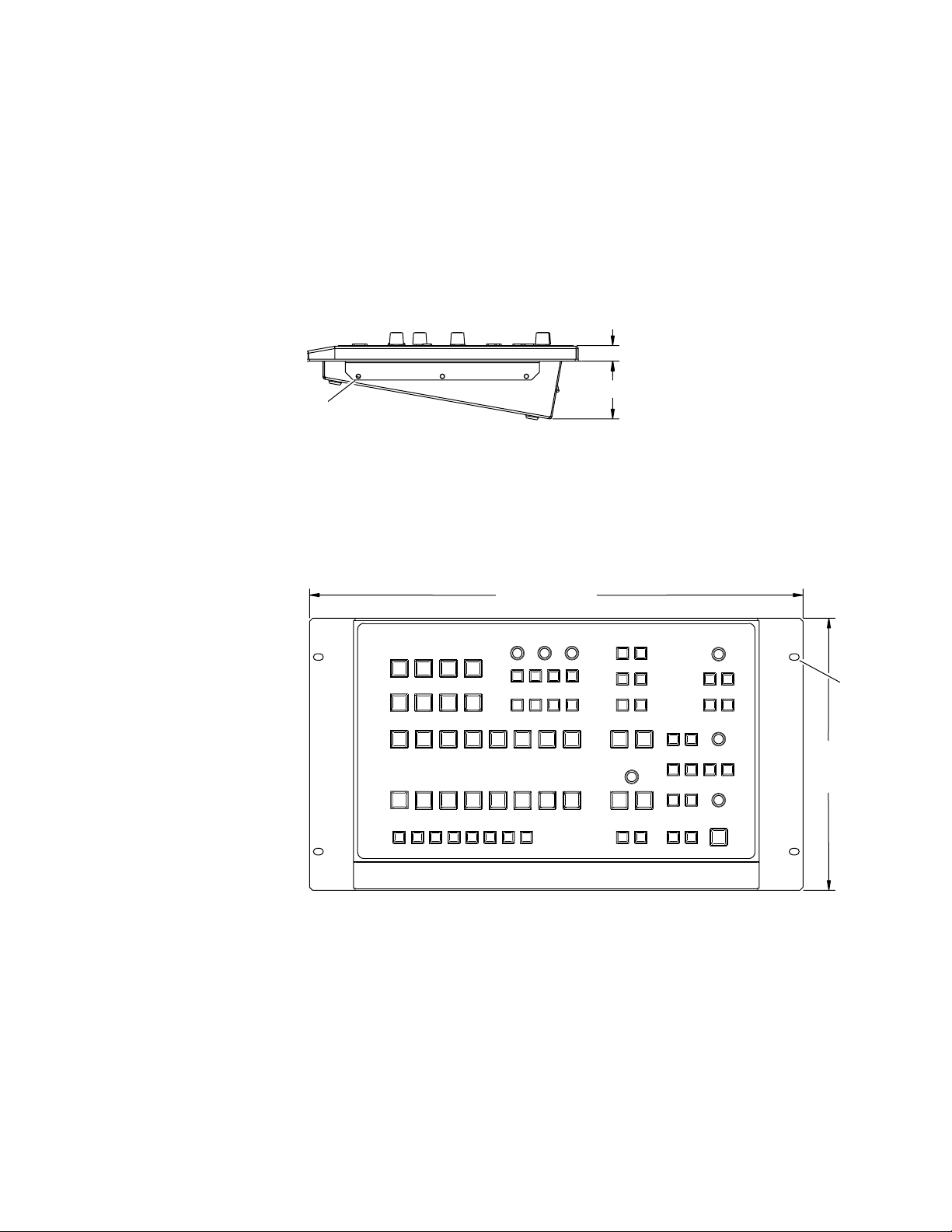
Control Panel Dimensions
The overall panel dimensions are illustrated in Figure 1-2 (top view) and
Figure 1-3 (front and right side views).
Figure 1-2. Top View Dimensions
15.62 in / 397 mm
10.47 in.
266 mm
8129_03
1-2 MMCP Installation/Operation Manual
Page 11
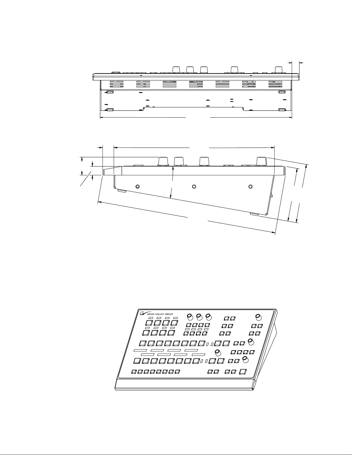
10.31 in.
262 mm
0.56 in.
14 mm
10°
9.20 in.
234 mm
14.50 in.
368 mm
0.64 in.
16 mm
1.03 in.
26 mm
0.5 in.
13 mm
3.39 in.
86 mm
3.07 in.
78 mm
Front view
Right side view
8129_04
Figure 1-3. Front and Right Side Panel Dimensions
Control Panel Installation
Tabletop Mounting
The MMCP panel can stand alone on a tabletop surface (Figure 1-4).
Rubber feet are installed on the bottom of the panel.
Figure 1-4. MMCP Tabletop Mounting
MMCP Installation/Operation Manual 1-3
8129_05
Page 12
Section 1 — Installation
Console Mounting
1.
2.
A mounting bracket option kit provides a console mounting bracket to
mount the control panel into a console cutout or rack ears to mount the
panel in a standard 19 in. rack.
To install the panel in a console cutout, perform the following steps:
Prepare the console cutout according to the dimensions in Figure 1-5.
Figure 1-5. MMCP Console Cutout Dimensions
2X If console thickness exceeds 0.375 in. / 10 mm
Route these areas from far side
9.37 in.
238 mm
4X R 0.125 in. / 3 mm permitted
This area through
14.62 in. / 371 mm
Console preparation as viewed from console top surface
Install the optional console mounting brackets to the right and left sides
of the panel using four of the #8 screws provided (Figure 1-6).
2X 0.75 in.
19 mm
2X 0.56 in.
14 mm
2X 5.25 in.
133 mm
4X 0.25 in.
6 mm
8129_06
Adjust the mounting bracket to position the panel in the console at the
desired height. Maximum console thickness is 0.375 in (10 mm). For a
console wider than this, route the areas from the far side as shown
above.
Figure 1-6. Attaching Console Mounting Brackets
2X
(right and left sides)
Right side view
8129_07
1-4 MMCP Installation/Operation Manual
Page 13
Rack Mounting
1.
2.
Control Panel Installation
To mount the control panel in a standard 19 in. (483 mm) rack, use the rack
ears provided with the mounting option.
To rack mount the panel, perform the following steps:
Install the rack ears to the right and left sides of the panel using the six
#8 screws provided as illustrated in Figure 1-7.
Figure 1-7. Install Rack Ears To Panel
0.6 in.
15.24 mm
2.22 in.
6X
(3 right and 3 left)
Right side view
56.38 mm
8129_08
Mount the assembly to a standard rack using four standard rack screws
and washers (not provided).
Figure 1-8. MMCP Rack Mounting
19 in. / 483 mm
Front view
4X
10.47 in.
266 mm
8129_09
MMCP Installation/Operation Manual 1-5
Page 14
Section 1 — Installation
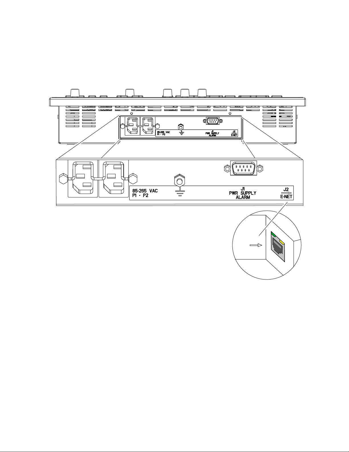
Control Panel Cabling
The connections to the MMCP panel are made at the rear of the panel in the
recessed area shown in Figure 1-9.
Figure 1-9. Control Panel Connections
Powering On
J2
ENET
8129_10
The MMCP has dual power supplies as standard features. The power supplies are installed inside the panel and are not accessible. There is no on/
off switch for either supply. To power on, connect the AC line cords to the
PS 1 and PS 2 AC connectors.
A chassis ground lug is provided at the rear of the panel.
1-6 MMCP Installation/Operation Manual
Page 15
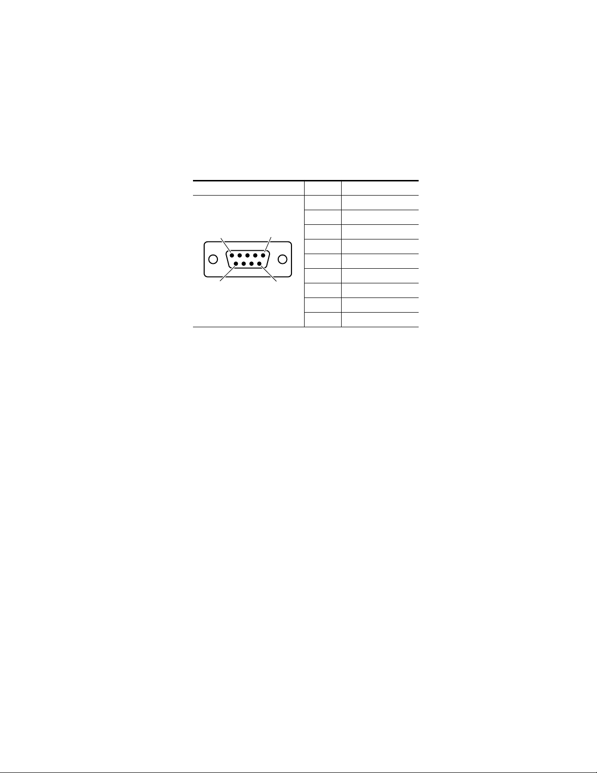
Power Supply Alarms
A 9-pin male connector at J1 provides a power supply status reporting port.
An external device can be wired to this connector to indicate when one or
both of the power supplies fail.
A pinout diagram for J1 is given in Table 1-1.
Table 1-1. Power Supply Alarm Connector Pinout
9-pin D Male Connector Pin Alarm Port (J1)
Pin
D-9 Male
1
Pin
6
J1
Pin
5
Pin
9
Control Panel Cabling
1 Normally Closed_1
2 Common
3 Normally Open
4 No Connection
5 No Connection
6 Normally Closed_2
7 No Connection
8 No Connection
9 No Connection
When both power supplies are working properly, Pin 3 (Normally Open) is
open with respect to Pin 2 (Common). If there is a power supply failure on
either AC circuit or power supply, Pin 2 and Pin 3 will close.
An external alarm may be attached to the connector to operate in one of the
following ways:
■
Connect an alarm between Pin 2 and Pin 3 to switch on when the AC
input or either power circuit fails or when either power supply fails.
■
Connect an alarm between either Pin 1 or Pin 6 and Pin 2 to open when
the AC input on either circuit fails or when either power supply fails.
Connect an alarm between Pin 1 and Pin 6 to open when the AC input
■
on either circuit fails or when either power supply fails.
Note
Connecting between Pin 1 and Pin 6 is recommended only when the alarm
relay is used to switch open an inductive load such as an AC-powered relay
that cannot otherwise be protected with an external shunt diode.
The alarm relay contacts should be rated for 100 mV to 28 V AC or DC at
100 to 500 mA.
MMCP Installation/Operation Manual 1-7
Page 16

Section 1 — Installation
Network Configuration
Setting MCP Net IP Address
The MMCP communicates with the M–2100 frames over a separate MCP
Net Ethernet network. The M–2100 frames communicate with other
external devices over the Facility LAN. The IP address of each panel must
be set to put it on the specific MCP Net where the frames it will control
reside. This must be done before you connect panels to the network.
If this is a new installation, you may use the default MCP Net IP addresses
of the panel and frame set at the factory. They should be on the same MCP
Net. If more than one panel or frame is present, you will need to change the
last octet of the MCP Net IP address of each of the additional devices. Each
device must have a unique IP address (first three octets are the same, the
last one different). The default IP address set at the factory for the MMCP
is 192.168.0.250.
If you are installing a panel into an existing network, you will need to
change the IP address of each panel so it is on the same MCP Net as the
frames it will be controlling (first three octets are the same, the last one different).
If you don’t know the MCP Net IP address of the existing network, you will
need to query your frame through Console Port J4 on the rear of the frame
to determine what MCP Net IP address has been assigned. Your network
administrator may also be able to tell you what IP addresses are used at
your facility.
There are two methods for setting the IP Address,
Using the Netburner PC Tool, or
■
■
Connecting a PC directly to the MMCP.
Netburner IPSetup PC Tool
The Ethernet card in the MMCP runs on the Netburner operating system.
You may use the Netburner IPSetup.exe PC tool included on the floppy
disk that accompanies the panel to set the IP address of the panel.
Note
This utility can also be downloaded free of charge from the Netburner.com
web site.
1-8 MMCP Installation/Operation Manual
Page 17
1.
2.
3.
4.
5.
6.
7.
8.
Control Panel Cabling
Use the following procedure to set the IP address using the Netburner PC
tool.
Connect a PC and one MMCP to the same 10 BaseT Ethernet network.
Note
Only one panel at a time should be connected to the PC to allow positive identification of the panel to be programmed.
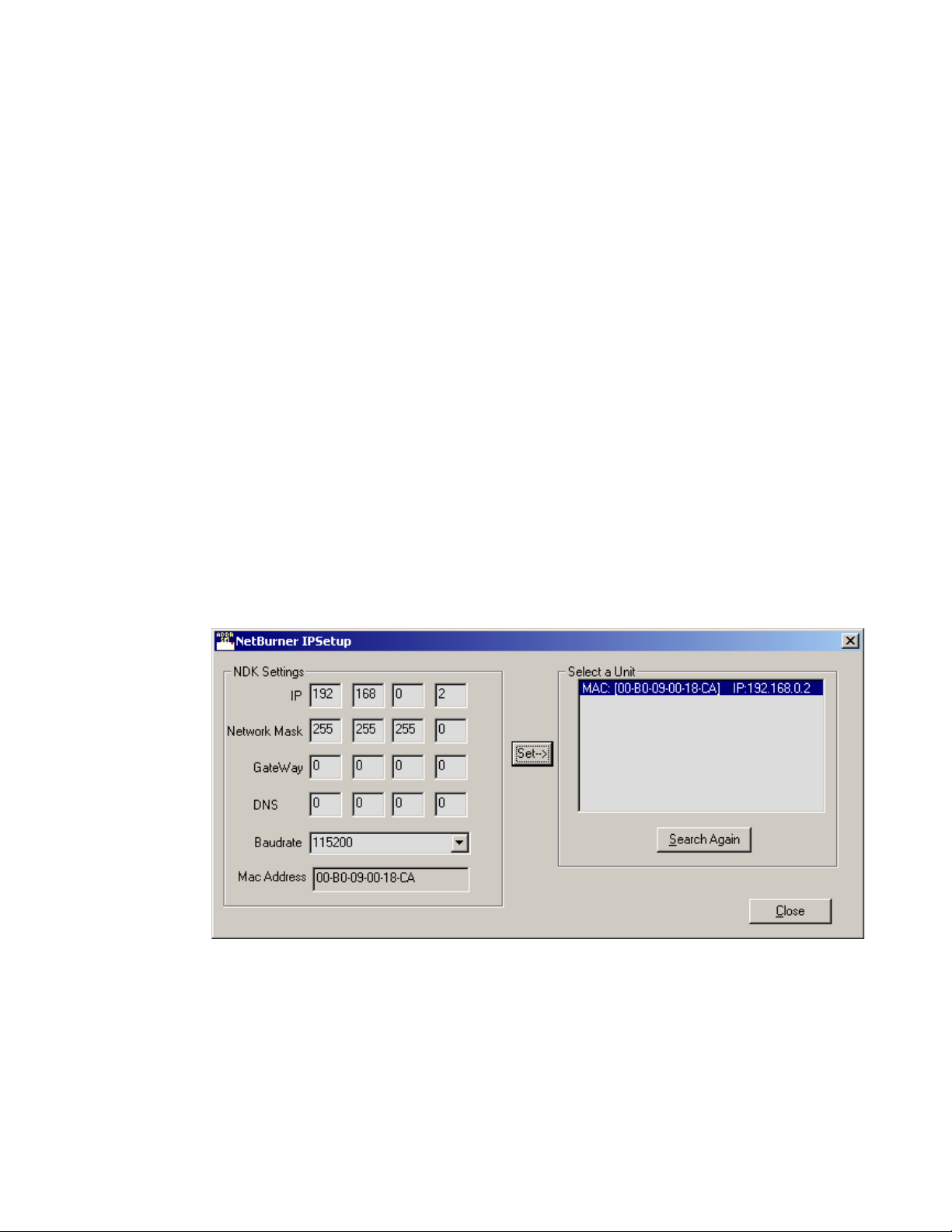
Open the Netburner IPSetup.exe application and locate the panel on
the network as shown in Figure 1-10. The application will find
Netburner devices on the network and identify them by their MAC
addresses.
Type in the desired IP address in the
Set the Subnet Mask in the
Set the
Set the
GateWay
DNS
IP address to 0.0.0.0.
IP address to 0.0.0.0.
When finished, click on the
Network Mask
Close
IP
boxes.
boxes to 255.255.255.0.
button.
The panel must be rebooted for the new IP address to take effect.
Remove power momentarily to reboot.
Figure 1-10. Netburner IPSetup PC Tool
MMCP Installation/Operation Manual 1-9
Page 18
Section 1 — Installation
1.
2.
Direct PC Connection
You may use a PC equipped with an Ethernet interface and a web browser
to change the panel IP address as follows.
Connect the PC’s Ethernet port directly to the MMCP panel ENET RJ45
connector J2 (Figure 1-9 on page 1-6).
Note
A crossover Ethernet cable (Tx/Rx pair crossed) is needed when connecting
a PC directly to the panel without a hub intermediary.
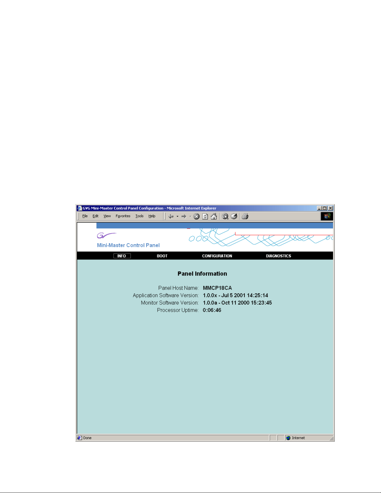
Run the web browser and type in the default IP address of the MMCP
panel as http://192.168.0.250. The PC IP address must have a network
value (first three octets) that matches the default IP address.
If the address is found, a
Panel Information
screen similar to Figure 1-11
will appear.
3.
Click on the
Figure 1-11. Panel Information Screen
BOOT
link to go to the Boot Configuration screen.
1-10 MMCP Installation/Operation Manual
Page 19
4.
5.
7.
Control Panel Cabling
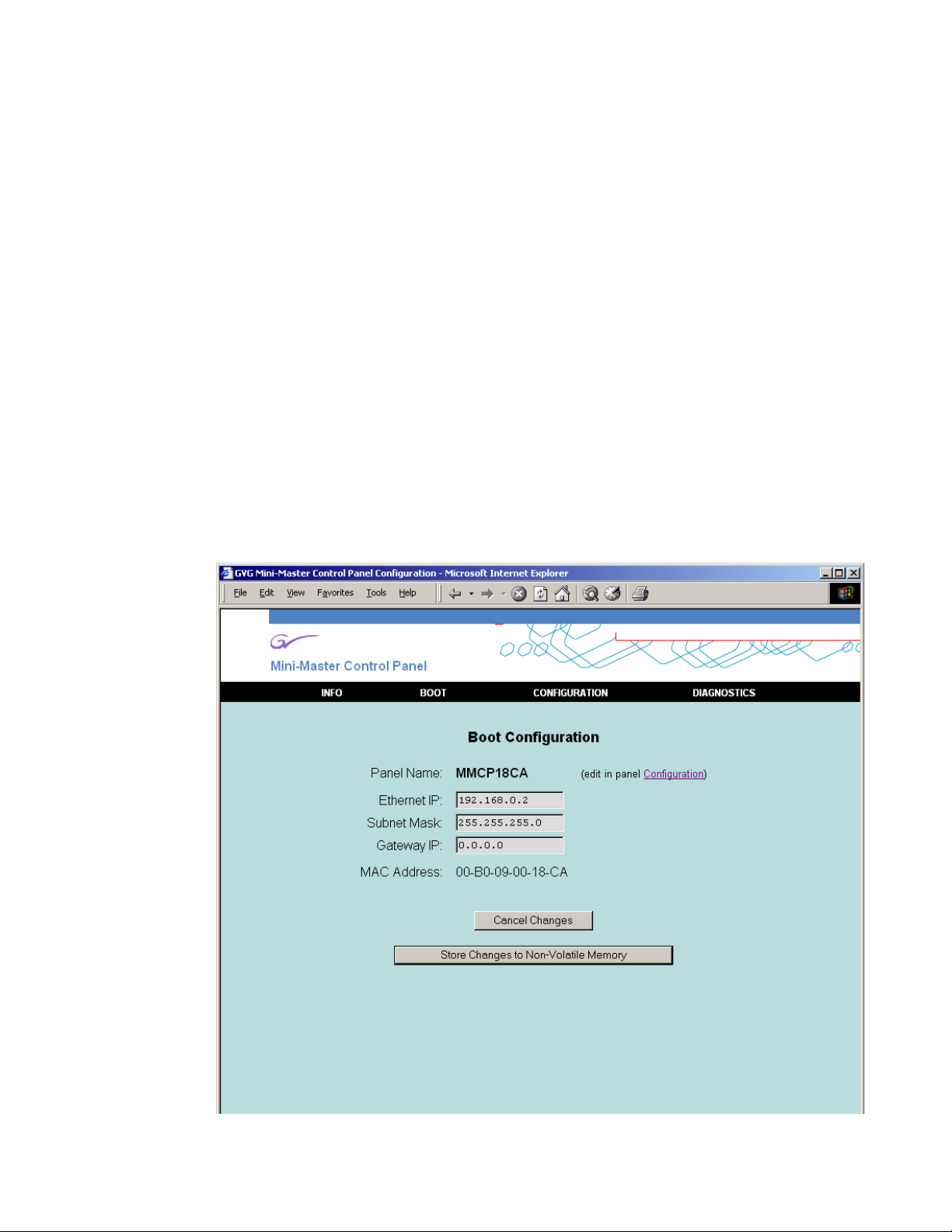
In the Boot Configuration screen (Figure 1-12 on page 1-11), enter the
Ethernet IP
address for this panel to put it on the MCP Net with the
frames it will be controlling.
8.
9.
The
Subnet Mask
should be 255.255.255.0 (the subnet mask for the
M–2100 network).
6.
Gateway IP
The
Select
should be set to 0.0.0.0.
Store Changes to Non-Volatile Memory
to store these values or
make no changes.
Note
The MAC address of the Ethernet card inside the panel is also given in readonly format.
Disconnect the panel from the PC and install it onto the MCP Net
Ethernet network.
Repeat this procedure on all the MMCP panels to be used with your
M–2100 system, entering unique MCP Net IP addresses (last octet
different) for each MMCP panel.
Figure 1-12. Boot Configuration Screen
Cancel
to
MMCP Installation/Operation Manual 1-11
Page 20

Section 1 — Installation
Control Panel Configuration
After installing the panel in the MCP Net and in its operating location you
may wish to adjust some of the operating parameters such as display and
low tally intensity and LED blink period. This can be done in the
figuration
menu also accessible through the web browser.
Panel
Con-
Return to the panel IP address location with the web browser by entering
the new IP address of the panel. From the
CONFIGURATION.
The
Panel
Configuration
screen will appear as shown in Figure 1-13 on
Panel Information
screen, click on
page 1-13.
You may set the following parameters from this screen:
■
Panel Name
■
LED Blink Period
— Enter a panel name of up to eight characters.
— Enter a number from 1–25 for a blink rate.
■
LED Low-Tally Intensity
— Enter a value from 1–9 (1=minimum to 9=max-
imum).
■
Display Intensity
— Enter a value from 1–7 (1=minimum to 7=maximum).
You may make channel assignments for each of the eight channel controls
on the panel from this menu. Enter the name of the channel (from the FCM
name assigned in M–2100 configuration). The name must be a valid FCM
name on the network. The preferred method of making channel assignments is by using the
Channel Control
Assigning Channels to Channel Control Buttons on page 2-4
When you have finished, click the
the intensity or blink rate parameters. Click the
Memory
to store these values or
buttons on the panel as described in
.
Use Changes Now
Cancel Changes
button to preview any of
Store Changes to Non-Volatile
to make no changes.
1-12 MMCP Installation/Operation Manual
Page 21
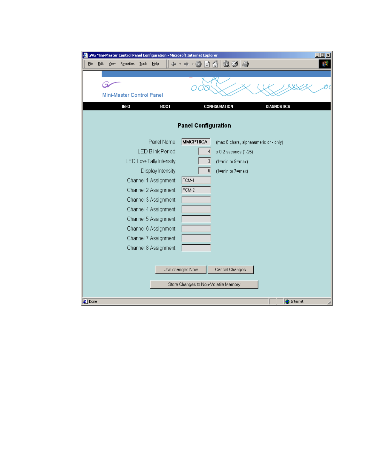
Figure 1-13. MMCP Configuration
Control Panel Cabling
MMCP Installation/Operation Manual 1-13
Page 22

Section 1 — Installation
Control Panel Diagnostics
Some control panel diagnostics are available through the
Diagnostics Mode
menu and from button presses on the panel pushbuttons.
Note
Diagnostics may only be run when the system is off-air and no FCMs are
communicating. Release all connected FCMs or clear all FCM assignments
from
Channel Control
buttons.
To perform diagnostics from the web browser, click on DIAGNOSTICS from
the
Panel Information screen.
The Diagnostics Mode screen will appear as shown in Figure 1-14 on
page 1-15.
You may perform the following diagnostic tests from this screen:
■ Switch Test — The LED display behind each switch will be cycled
through bright, dim and off states. For switches with two LEDs, both
LEDs will be cycled though all combinations.
■ Lamp Test — All LEDs will be turned on in sequence. The current LED
number will be displayed.
■ Display Test — All displays are identified by number while the intensity
is cycled through all states. All possible ASCII characters are also
cycled.
■ Knob Test — An absolute signed value will be shown for each shaft
encoder. Turn knobs to send delta values to the frame. Press any button
to clear and reset the displayed values.
Click the
parameters. Click the
or
Cancel Changes to make no changes.
Use Changes Now button to preview any of the intensity or blink rate
Store Changes to Non-Volatile Memory to store these values
The panel diagnostics may also be initiated directly from the panel pushbuttons as follows:
1. Press and hold the unlabeled white button below the GPI 2 button in the
User control section of the panel.
2. Press one of the top four Channel Control buttons to run the
diagnostics. The four buttons correspond to the diagnostic tests above
(Channel 1=Switch Test, Channel 2=Lamp Test, Channel 3=Display
Test and Channel 4=Knob Test).
3. To turn diagnostics off, press and hold the unlabeled button and select
any one of the bottom four
Channel Control buttons.
1-14 MMCP Installation/Operation Manual
Page 23
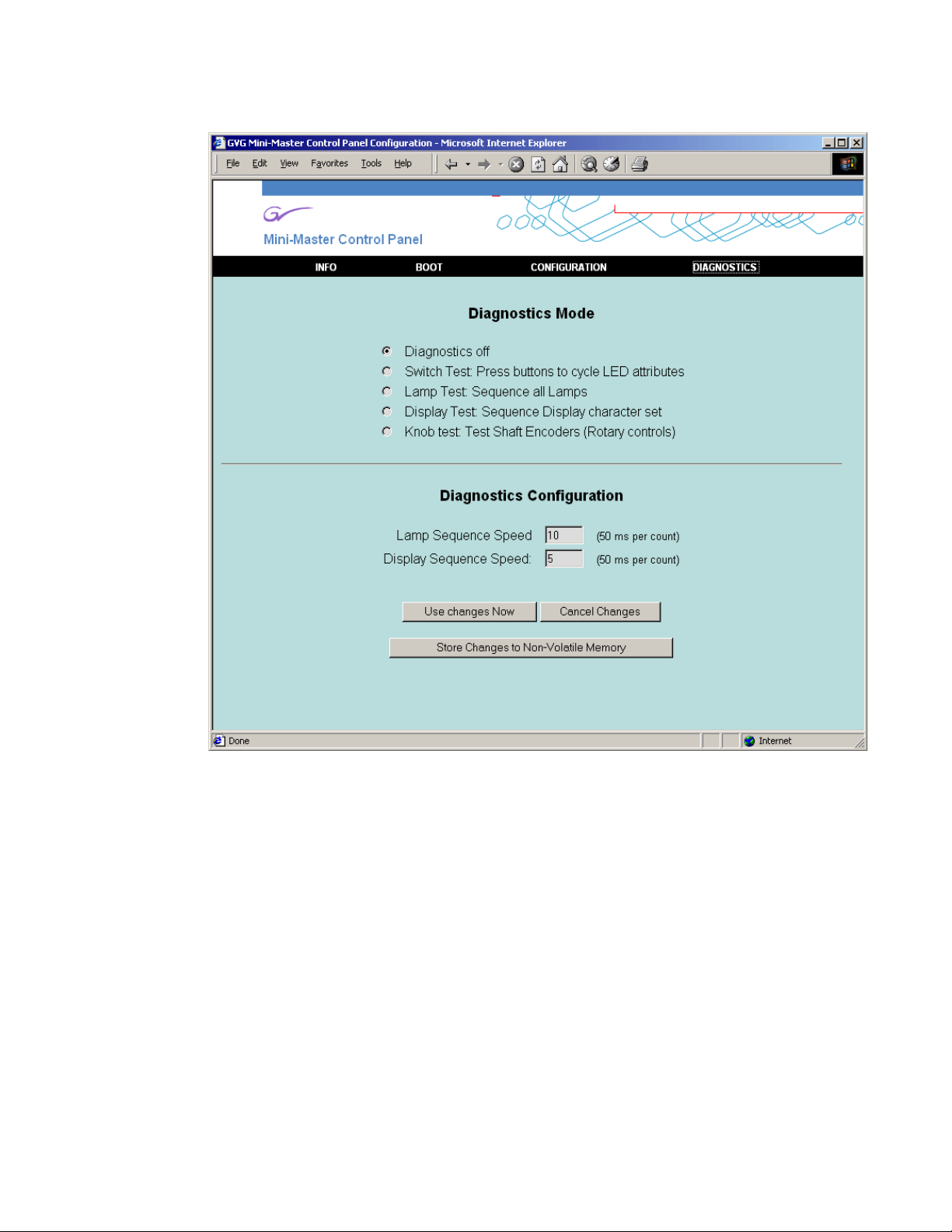
Figure 1-14. MMCP Diagnostics Screen
Control Panel Cabling
MMCP Installation/Operation Manual 1-15
Page 24
Section 1 — Installation
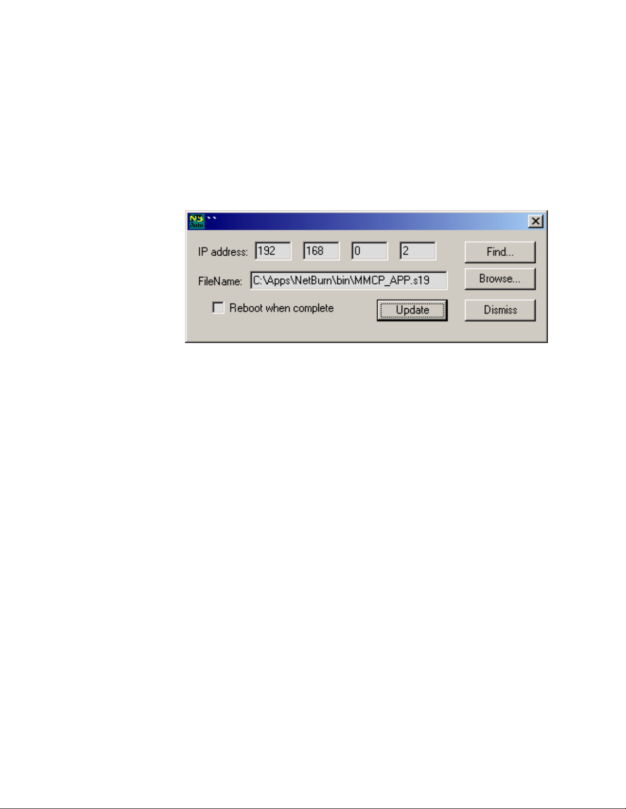
Software Installation
The MMCP requires that the M–2100 is running v5.0 or later software.
When new system software is released, installation is done with the Netburner AutoUpdate PC Tool shown in Figure 1-15. Instructions for using
the tool are given in the Release Notes that accompany the upgrade. The
Release Notes will also cover new operating and configuration information.
Figure 1-15. Netburner AutoUpdate PC Tool
System Configuration
After installing new software, you will need to configure the system with
Configuration Manager. The
panel parameters. Refer to your M–2100 Installation and Service Manual
for complete instructions.
MCP form in this application is used to set the
1-16 MMCP Installation/Operation Manual
Page 25

System Operations
About this Section
This section of the Mini Master Control Panel Installation and Operation
manual describes the basic operation of the MMCP. The operations are
described using step-by-step procedures.
The topics covered in this section are:
■ Multichannel operations,
■ Program/Preset bus operations,
■ Transition controls and operation including Transition Type and Rate,
Breakaway Mode, Next Transition, and PreRoll/Transition button groups,
Section 2
■ GPI button operations,
■ Mode/Function button operations,
■ Keying controls and operations including keys and key modifiers,
Chroma keying, SqueezeBack and Crop, and
■ Audio Controls and operations including audio monitoring.
MMCP Installation/Operation Manual 2-1
Page 26
Section 2 — System Operations
Introduction
The Mini Manual Control Panel shown in Figure 2-1, provides an alternative to automated control of the M–2100 Serial Digital Master Control
System. A single MMCP can control up to sixteen channels (frames), eight
channels selectable at any given time. Automation can be disabled at the
MMCP for each of the Audio/Video/Control Processors.
Figure 2-1. Mini Master Control Panel
PGM Bus
PGM
PROGSRC1
PST
Channel Controls Automation Controls Keyer Controls GPI Buttons (2) Audio Monitor Controls
MINI MASTER CONTROL
Channel Control
Video
PROGSRC3 PROGSRC5 PROGSRC7
PROGSRC2 PROGSRC4
Transition
Rate
Keyer Control
Hue
Clip
PROGSRC6
Gain
Sat
Bright
Opacity
PROGSRC8
V
Non Sync
Non Sync
User
Audio
A
Primary
V
A
Mode
Over
Ratio
Next Transition
Audio Monitor
Monitor
Volume
PGM Level
PST Level
Transition
PreRoll
Transition
Mo de
Func
8129_12
Transition Rate Buttons (3)
Transition Type Buttons (5)
Source DisplaysPST Bus
Next Transition ButtonsAudio/Video Breakaway Mode
PreRoll/Transition Button Audio Controls
Mode/Function Button
2-2 MMCP Installation/Operation Manual
Page 27

Using Multichannel Control
A powerful feature of the M–2100 is the ability to control more than one
processing channel (FCM). A Channel Control subpanel (Figure 2-1 on
page 2-2) located in the top left corner of the panel, allows you to:
■ Enable/disable automation for each channel,
■ Assign Channel Control buttons to specific channel (Frame Controller
Modules or FCMs),
■ Control chosen FCMs using MMCP controls, and
■ Monitor channel status.
Channel Control Overview
The Channel Control subpanel (Figure 2-2) allows control of up to eight
channels from the panel. The panel will respond to the lamps and tallies for
only one panel at a time. This is the Primary channel. Up to seven Secondary channels can be assigned; one of which can be chosen to replace the
Primary fails for some reason. Assigned and connected channels do not
have to be selected as Primaries or Secondaries. The color and state (bright
or dim) of the
nected channel (see Table 2-1 on page 2-4).
Channel Control buttons will indicate the status of each con-
Using Multichannel Control
The
Channel Control buttons also enable and disable automation of any asso-
ciated assigned channel and show automation status with the yellow LED
above each button.
Figure 2-2. Channel Control Subpanel
Channel Control
Ch 1
Ch 5
Ch 2
Ch 6
Ch 3 Ch 4
Ch 7 Ch 8
8129_13
MMCP Installation/Operation Manual 2-3
Page 28

Section 2 — System Operations
The Channel Control button color, tally states and their meanings are summarized in Table 2-1.
Table 2-1. Channel Control Button Color and Tally States
Dim Red (blinking) Assigned pending connection
When assigning a channel, you may scroll through the available channels
with the
panel (Figure 2-1 on page 2-2).The scrolling channel names will appear in
a Source Name display (Figure 2-3) corresponding to the
button being pressed. Once channels are assigned to a button, the channel
names will be displayed in the Source Name displays corresponding to the
Channel Control buttons.Channel names will only display during the channel
assignment process.
Color/State Meaning
Off Not assigned
Dim Red Assigned but not available (Busy or No Comm)
Dim Green Assigned and connected
Bright Yellow Primary channel
Dim Yellow Secondary channel
Alternating Red Non-sync
Take and Fade/Fade Transition Type buttons in the lower left of the
Channel Control
Figure 2-3. Channel Names in Source Name Displays
Channel 1
Channel 5 Channel 6
Channel 2 Channel 3
Assigning Channels to Channel Control Buttons
Each frame (channel) must be currently configured as a valid Equipment
Type in Configuration Manager before it can be assigned to a
button.
Channel Control buttons can only be assigned when the panel is in a quiescent
state (no Primary active and all panel lights off).
To assign channels, do the following:
1. Press and hold down the Mode/Function button on the far right of the
panel between the PGM and PST Level audio controls (Figure 2-1 on
page 2-2).
Channel 7
Channel 4
Channel 8
8129_24
Channel Control
2-4 MMCP Installation/Operation Manual
Page 29

Using Multichannel Control
2. Press and hold down one unassigned Channel Control button whose
button state is off.
3. Release the Mode/Function button. Continue to hold down the Channel
Control button.
4. Use the first two buttons, Take and Fade/Fade, in the Transition Type
subpanel to scroll through the list of available valid channel names
displayed in the Source Name display corresponding to the selected
Channel Control button (Figure 2-3 on page 2-4).
Note Frame names already assigned will not appear in the list.
5. When the desired FCM name is found, and while continuing to hold
the
Channel Control button, press and release the Mode/Function button.
6. Release the Channel Control button. The FCM name is assigned to the
associated
Channel Control button and the button will light dim green to
indicate it is assigned and connected or dim red if it is assigned but not
available. Refer to Table 2-1 on page 2-4 for a summary of other status
states.
7. To delete an assignment, scroll through the list and assign None to the
button.
In addition to the above functionality, an assigned and connected (dim
green status) channel may be released to allow another control panel to
acquire it without changing the assigned FCM name stored in non-volatile
memory.
To release a channel for use by another MCP, do the following:
1. Press and hold the Mode/Function button.
2. Press and hold the appropriate Channel Control button.
3. Release the Mode/Function button and momentarily press it again.
MMCP Installation/Operation Manual 2-5
Page 30

Section 2 — System Operations
Assigning Primaries and Secondaries
Any button that is displaying dim green status may now be selected as a
Primary or Secondary channel.
A Primary channel is active and on-air. Any changes made on the panel
controls will affect this channel. Its status is indicated by the corresponding
Channel Control button tallying bright yellow. Only one Primary channel may
be selected at a time.
A Secondary channel can be selected but is not on-air. Its corresponding
Channel Control button will light dim yellow. If the Primary channel fails, the
operator can select the Secondary and it will be in the same panel state as
the Primary. Up to seven Secondaries can be selected.
Selecting a Primary or Secondary Channel
To select a Primary channel, press a Channel Control button with dim green
status. The button will now tally bright yellow indicating it is the active
Primary channel.
The following behavior applies to a selected Primary:
■ Pressing the button again will deselect it as the Primary.
■ Pressing and holding the Primary button and selecting and releasing
another button with dim green status will assign that button as a Secondary (dim yellow). The Primary button will not lose its status.
■ If no Secondary is selected, releasing the Primary button will result in
its de-selection as Primary. It will return to a dim green status. Select it
again to return it to the Primary channel.
■ Pressing another dim green or dim yellow (Secondary) tallied Channel
Control button will select the associated channel as the Primary. All other
previously selected channels (Primary and Secondary) will be deselected (return to dim green status).
Pressing an already selected Primary when there are Secondaries will have
the following affects:
■ While held down, Secondaries can be de-selected by pressing and
releasing their button. The Primary remains unaffected.
■ While held down, new Secondaries can be selected by pressing and
releasing their associated button. The Primary remains the Primary.
■ When the Primary button is released, and if no Secondaries have been
selected or de-selected, all Secondaries are de-selected. The Primary
remains selected.
2-6 MMCP Installation/Operation Manual
Page 31

Automation Enable
The Channel Control buttons are also used to enable/disable automation
control for the corresponding channel.
Automation Control can be enabled/disabled for all eight channels independently of the
have to be chosen as a primary or secondary in order to enable/disable
automation.
To enable/disable automation on a channel, do the following:
1. Press and hold the Mode/Function button.
2. Press and release the Channel Control button corresponding to the
automation control you wish to enable or disable.
3. The corresponding yellow LED above the Channel Control button
(Figure 2-2 on page 2-3) will light when automation control of the
channel is enabled and go off when control is disabled.
Using Multichannel Control
Channel Control buttons status. That is, a channel does not
MMCP Installation/Operation Manual 2-7
Page 32

Section 2 — System Operations
Program and Preset Bus Operations
Preset Bus
The Preset bus (PST) (Figure 2-4) is a row of eight source select crosspoint
buttons. Each crosspoint button may be mapped to an input source from
the rear of the Processor frame. The crosspoint buttons are initially configured at the factory so that the sources are associated in ascending numeric
order from left to right. The left-most button corresponds to Source 1; the
right-most button corresponds to Source 8. This order may be changed in
the
Main Sources form, under PGM/PST/Aux Sources tab in Configuration Man-
ager.
The crosspoint buttons can be mapped to any input source desired. It is not
necessary to map Crosspoint 1 to Source 1, for example, it may be assigned
to any of the sources. Each source consists of video and like-numbered
audio inputs. For instance, video at input 1, and all audio connections to
input 1 (from one to four channels), are all part of the same source, Source 1.
Figure 2-4. Program (PGM) and Preset (PST) Buses
Video
PGM
PST
1
PROGSRC1
PROGSRC2 PROGSRC4
1
2 3 4 5 6 7 8
PROGSRC3 PROGSRC5
2 3 4 5 6 7 8
Selecting Preset Sources
PST buttons can select main audio/video (married) sources and/or sources
for Audio Processor Modules 1–4. To select a Preset source, do the following:
1. Press the PST button corresponding to the desired source.
PROGSRC7
PROGSRC6
PROGSRC8
V
A
Non Sync
V
A
Non Sync
8129_20
The selected
source of both video and audio signals. All other
PST button lights at high tally, indicating that it is the
PST buttons go dark.
2. If Next transition Bkgd tallies high, the selected Preset source will be output
on the Look Ahead Preview (LAP) output.
2-8 MMCP Installation/Operation Manual
Page 33

If video and audio monitors have been connected, you can view, hear,
and adjust the Preset source prior to taking it to the Program bus.
The audio level and trim settings that existed on the selected source when
last placed on the Program bus are recalled.
Backup Preset Sources
The M–2100 has the ability to maintain a backup source. A backup source
can be taken to air on the Program bus if the primary source fails.
You may enable another Preset source to act as a backup if you have
checked the
ration Manager. If backup capability has not been enabled, simultaneous
pressing of more than one
any effect.
If a backup source has been enabled in Configuration Manager, enable a
backup source as follows:
1. Press and hold a PST button (which will tally high) to select the primary
source.
Enable Backup Input Select check box in the MCP form in Configu-
Program and Preset Bus Operations
PST button results in only the leftmost having
Program Bus
2. Press and release a second PST button to select a backup source (which
will tally high/blinking). If this was the incorrect backup selection,
change the backup crosspoint by holding down the Primary
and pressing and releasing another
be replaced by the second.
Pressing and releasing the
swapped with the primary married source — the backup source becomes
the primary married source and the previous primary married source
becomes the backup source.
Pressing and releasing the
cause the backup source to be dropped.
When the Preset source is transitioned to the Program bus (on-air), the
backup source will follow and may be selected manually as a backup if the
original source fails. This is normally done with two identical sources
rolling the same tape or clip.
The Program bus (PGM) is a row of eight source select crosspoint buttons
(Figure 2-4 on page 2-8). Crosspoints assignments are made as described in
Preset Bus on page 2-8 and follow the Preset bus.
PST button of a backup source will cause it to be
PST button of the primary married source will
PST button. The first selection will
PST button,
MMCP Installation/Operation Manual 2-9
Page 34

Section 2 — System Operations
Sources active on the Program bus are sent to the Program output. This is
typically the output being supplied to the station transmitter. In routine
operation, sources are preset on the Preset bus, then transitioned to the
Program bus.
When a transition is made with the
PreRoll/Transition button, or automation,
sources selected on the Preset bus are transitioned to the Program bus, and
PGM button tally changes accordingly. For fade-type transitions, PGM button
tally changes in the frame during which new video first appears on the
Program output bus. For mixes,
PGM button tally changes when the transi-
tion is complete.
If more than one
PGM buttons can select main audio/video (married) sources and/or
PGM button is pressed, only the left-most has an effect.
sources for Audio Processor Modules 1–4.
Backup sources cannot be chosen on the Program bus, only the Preset bus,
as explained above.
Backups can be transitioned to the Program bus, but cannot be Tally
Summary for Program and Preset buses. A summary of the
PGM button
tally states is given in Table 2-2.
Table 2-2. PGM Button Tally
Button Tally Indication
Off Not selected
Low Audio breakaway
High
High/blinking Married backup source
Initialize
Primary married source
Primary video source
Left-most button (Source
#1) tallies high
Source Names Display
The Source Name displays are located directly above the Program bus
buttons (Figure 2-4 on page 2-8). They display an 8-character name for each
source. Source Names are defined in Configuration Manager,
form,
PGM/PST/AUX Sources tab.
The names displayed are usually those associated with the main sources,
but may be used to display names for optional Audio Processing Channels
2, 3, and 4.
The Source Name displays will also report the assigned channel names corresponding to the
Channel Control buttons when the panel is in a quiescent
state, as when channels are being assigned (Figure 2-3 on page 2-4).
2-10 MMCP Installation/Operation Manual
Main Sources
Page 35

If a particular input has been configured as a Router Linked Destination,
the name displayed is one of the following:
■ If SMS7000 communications are active, the name displayed will be the
source name provided by the SMS7000 (in software v5.1 or later).
■ If SMS7000 communications are not active for a set time, the name dis-
played will be *NOLINK*.
■ If the proper SMS7000 destination name has not been entered into Con-
figuration Manager, the name displayed will be *NODEST*.
Non-Sync Source Indicators
Two sets of indicators for non-synchronous sources video (V) and audio
(A) are located at the end of the Program and Preset rows (Figure 2-4 on
page 2-8). The video non-sync indicators display status on the corre-
sponding Program and Preset bus. The two audio non-sync lamps are tied
together. When either bus has an audio non-sync condition, both lights will
indicate non-sync.
Program and Preset Bus Operations
Non-sync conditions for audio and video are defined in Table 2-3.
Table 2-3. Non-sync Conditions
AUDIO buttons high tallies
PGM VIDEO button high tallies
PST VIDEO button high tallies
Note Non-sync backup sources are not reported.
Some aspect of audio for a selected source (primary, breakaway, Over)
on the Program or Preset bus is not in sync.
Some aspect of video for a selected source (primary, breakaway) on the
Program bus is not in sync.
Some aspect of video for a selected source (primary, breakaway) on the
Preset bus is not in sync.
If a Program source goes non-sync, the selected Transition Type button will go
low tally and the
Take button will go high tally.
MMCP Installation/Operation Manual 2-11
Page 36

Section 2 — System Operations
Transition Controls and Operation
A transition is a change from one combination of video and audio elements
(or sources) to another combination. These elements can be any of the following:
■ Married — video and audio supplied on the same crosspoint.
■ Video Only — video only signal supplied on this crosspoint.
■ Audio Only — there are four Audio Only PGM/PST crosspoint but-
tons, located on the Audio Control portion of the Manual Control
Panel.
■ Custom Transitions — split audio/video transitions by assigning them
different parameters in the Configuration Manager. You can configure
separate transition types, transition durations, and other associated
parameters. This is a software enabled option.
The following transition control buttons are explained in this section:
■ Transition Type
■ Transition Rate
■ Audio/Video Breakaway (Mode)
■ Next Transition
■ PreRoll/Transition
The following transition types are also explained in this section:
■ Custom transitions
■ Hot switching on the Program bus (Take)
Transition Type
In normal operation, Preset sources are transferred to the Program bus
through a transition. Transitions allow you to replace the current Program
output with the Preset source at a selected transition rate. There are five
standard transition types. The
MMCP are shown in Figure 2-5.
Figure 2-5. Transition and Rate Buttons
Transition and Rate pushbuttons on the
Transition Rate
Slow Med Fast
8129_22
2-12 MMCP Installation/Operation Manual
Page 37

From left to right, the Transition Type buttons select:
■ Take — provides a clean, abrupt switch from Preset to Program. Not
■ Fade/Fade — causes the current on-air source to fade down to transition
■ Take/Fade — causes the current on-air source to go abruptly to transition
■ Mix — causes the current on-air source to dissolve to the new source
■ Fade/Take — causes the current on-air source to fade down to transition
Transition Rates
Transition Controls and Operation
affected by transition rate selection.
matte/silent, at which point, the Preset source will fade up (to on-air)
from transition matte/silent.
matte/silent, at which point, the Preset source fades up (to on-air) from
transition matte/silent.
selected on the Preset bus.
matte/silent, at which point, the Preset source switches cleanly and
abruptly to on-air.
There is a Transition rate associated with each transition type. When a transition type is selected, the rate in effect when that transition type was last
used will be recalled. A
Take transition has no rate associated with it.
The transition rate applies the next time the
pressed, and is defined as the interval from the time the on-air video begins
to be modified to the time the preset audio and video is on-air at full gain.
Transition Rate buttons (Figure 2-5 on page 2-12) are labeled Slow, Medium, and
Fast.
The transition rates are set at the factory to the default values below:
■ Slow — default is 2.0 seconds
■ Medium — default is 1.0 second
■ Fast — default is 0.5 second
Transitions rates are set in the
M–2100 Configuration Manager. You may enter the desired transition rate
for each
Transition Rate button.
Hot Switching (Hot Program Cuts)
PreRoll Transition button is
Transition Rates section of the MCP form in the
A hot cut (also called hot punching) is a method used to select a source
directly on the Program bus. A hot cut always initiates a
Take transition. If
the selected video source is not present, the LOS (Loss Of Signal) Matte is
placed on-air. When LOS Matte is active, a continuous high/low tally
flashing occurs on the active
PGM button.
MMCP Installation/Operation Manual 2-13
Page 38

Section 2 — System Operations
If the hot cut is performed on a crosspoint configured with a preroll
enabled, the hot cut initiates the preroll sequence.
If the crosspoint is configured with a machine start or relay enabled, the hot
cut triggers the configured device.
The following hot cut actions will apply to transitions on the M–2100:
■ Hot cuts from the Program bus will take precedence over any transition
■ Hot cuts from automation will not be accepted if any transition (from
■ Hot cuts from the Preset bus will take precedence if the Enable Transition
■ Hot cuts will remove any selected keys or SqueezeBack selections if
Hot Cut Transition Interrupts
in progress, either from the MMCP or automation.
the MMCP or automation) is in progress.
Interrupt check box has been selected in the MMCP form in Configura-
tion Manager.
they are on-air.
A transition interrupt situation occurs when a new Program source is
selected during a transition in progress. The following functions take place:
■ Any Preroll/Transition is canceled.
■ Any Program bus Audio Overs are cancelled.
Selection of a Program audio source will recall the audio level and trim settings in effect when that source was last selected on the Program bus.
Custom Transitions
You can customize audio/video transitions by assigning them different
parameters in Configuration Manager. Custom separate transition types,
transition durations, and other associated parameters can be configured. A
combination of custom transitions and standard transitions is available.
Note This feature, called the 2100-SAV (Split Audio Video) is a software enabled
Refer to the Installation and Service Manual for complete configuration
instructions. Custom transitions are configured in the
Custom Transitions menu.
option and must be purchased.
MCP form, in the
2-14 MMCP Installation/Operation Manual
Page 39

Using Custom Transitions
Having previously defined your custom transitions using the Configuration Manager, you select a custom transition type as you would a standard
transition type. For example, if you set up a custom transition for Button
Type
Custom2, selecting the Mix transition button on the MMCP invokes that
custom transition.
Transition Rates
The transition rate is established by the parameters set up in the Custom Tran-
sition Configuration form. All of the Transition Rate buttons will low tally to
indicate that a custom transition is selected.
When a custom transition is active, and a Take transition occurs, the three
Transition Rate buttons tally off to indicate that the take is in progress.
Transition Rate Button Tally
The Transition Rate buttons (all three) display low tally when a custom tran-
sition is selected and active on the MMCP.
Transition Controls and Operation
Matte Duration
Any matte duration times are considered part of the New video.
When using SqueezeBack with matte transitions, the matte is disabled.
Changing from Custom to Standard Transition Types
To revert to standard transition types from Custom Transition types, do the
following:
1. In Configuration Manager, click on the Custom Transition button on the
MCP form.
2. In the Custom Transition form, uncheck the Enable Custom Transition check
box for each
3. Download the named configuration to the FCM.
Button Type that was customized.
Transition Interrupts
When custom transitions are selected and active, you can only make a hot
cut on the Program bus.
Transition Logging Tool
The Transition Logging Tool will accommodate custom transition types.
Custom transitions types may be logged with the Transition Logging Tool,
similar to the standard transition types.
MMCP Installation/Operation Manual 2-15
Page 40

Section 2 — System Operations
If a selected Transition Type has been defined as custom, the following data
will be displayed in the left pane of the main application window:
■ The TranType column displays the custom transition type, for example;
■ The (transition) Rate column displays the rate set for the selected
Custom1, Custom2, Custom3, etc.
custom transition based on the parameters set in the Configuration
Manager,
MCP form in the Custom Transition section.
2-16 MMCP Installation/Operation Manual
Page 41

Audio/Video Breakaways
Transitions can be tailored to change only selected signals using the Mode
(Audio and Video Breakaway) transition selections (Figure 2-6). Normally,
audio and video signals are transitioned simultaneously. The
Video Only buttons are used to perform program and preset bus breakaway
source selection. These buttons transition audio only or video only signals
as described below:
■ Audio Only—when selected, the next transition will change only the
audio portions of the on-air signal.
■ Video Only—when selected, the next transition will change only the back-
ground video portions of the on-air signal.
Figure 2-6. Audio and Video Breakaway Mode Buttons
Mode
Transition Controls and Operation
Audio Only and
Video
Only
Audio
Only
8128_18
Pressing either the Audio Only or Video Only button causes it to toggle between
its active and inactive state. Preset selections made while the
Video Only button is in the active state (lighted), unless the button is held,
will be restricted as indicated. If an
when a Preset selection is made, the
Audio Only or Video Only button is active
Audio Only or Video Only button will
Audio Only or
toggle to its inactive state automatically.
A typical
Video Only breakaway operation would be:
1. Press and release Video Only, then,
2. Press the desired Preset video source.
A typical
Audio Only breakaway operation would be:
1. Press and release Audio Only, then
2. Press the desired Preset audio source.
Note You cannot have a Backup set while performing Breakaways.
Breakaway Program or Preset bus selections (no Backup Presets) tally as
follows:
■ Video — high, steady
■ Audio — low, steady
MMCP Installation/Operation Manual 2-17
Page 42

Section 2 — System Operations
Breakaway Selection Examples
Audio Only Breakaway Example #1
1. Select VTR2 on Preset. Tallies high.
2. Select Breakaway Audio Only. Tallies high.
3. Select RS3 on Preset. Tallies low. Audio Only tallies off.
The next transition will take video from
1. Press the Preroll/Transition button.
2. On Program bus, VTR2 tallies high and RS3 tallies low.
VTR2 and audio from RS3.
Video Only Breakaway — Example #2
1. Select RS3 on Preset. Tallies high.
2. Select Breakaway Video Only. (tallies high).
3. Select VTR2 on Preset. Tallies high. RS3 on Preset changes to tally low.
Video Only tallies off.
The next
Program bus,
Preroll Transition takes video from VTR2 and audio from RS3. On
VTR2 tallies high and RS3 tallies low.
2-18 MMCP Installation/Operation Manual
Page 43

Next Transition Buttons
The Next Transition buttons (Figure 2-7) select whether the next transition will
consist of Background only, Key only, or both. The two buttons are:
■ Next Transition BKGD (Background) — when selected, the next transition
will change only the Background video portions of the on-air signal,
and
■ Next Transition KEY — when selected, the next transition will change only
the Key video portions of the on-air signal.
Both buttons may be selected simultaneously.
Figure 2-7. Next Transition Buttons
Next Transition
BKGD KEY
Transition Controls and Operation
8129_19
If an attempt is made to setup a Key-only transition while Audio Only is
active, there will be a beep audio warning and the setup is ignored.
If an attempt is made to press the
BKGD button during preroll, it will be
beeped and ignored.
If an attempt is made to press the
KEY button during preroll, it will be
ignored (that is, it will not change its state) but not beeped. This button
press is allowed since key cuts are allowed during preroll.
If one of the buttons tallies high and the other tallies off, the buttons will act
as follows:
■ Pressing and releasing the high tallied button has no effect. It stays high
tally.
■ Pressing and releasing the off tallied button will cause it to tally high.
The other button tallies off.
■ Pressing and releasing both buttons simultaneously results in both tal-
lying high.
If both switches tally high, the buttons will act as follows:
■ Pressing and releasing either will leave that button’s tally high and turn
the non-pressed button’s tally off.
■ Pressing and releasing both buttons simultaneously will have no effect
— both continue to tally high.
If
KEY tallies high, and there are no Key Select buttons in the active state (that
is, with high tally) the next transition will have no effect.
MMCP Installation/Operation Manual 2-19
Page 44

Section 2 — System Operations
Holding the Key button down can have special effects, as described in
Cutting Keys On or Off Air on page 2-26. (If a Key-cut occurs, releasing the
button does not change its tally.)
Preroll Transitions
A preroll transition causes Preset sources to begin prerolls (if configured),
then transition to the Program bus. Preroll transitions can be triggered by
pressing the
that has been configured with a preroll enable.
Figure 2-8. PreRoll/TransitionButton
Transition
Key
PreRoll/Transition button (Figure 2-8) or by selecting a crosspoint
PreRoll
Transition
8129_21
The PreRoll Transition button tallies three conditions:
■ Full brightness — Transition in progress,
■ Half brightness — One of the selected Preset sources has been config-
ured with a preroll time, and
■ Off — No selected Preset source has been configured with a preroll
time.
There are several scenarios involving the use of the
and the transition type selected as described in the following headings:
First Press Transitions
■ Begins a preroll (if any).
■ Makes a Preset bus-to-Program bus transition (no preroll), or at the end
of the preroll interval.
PreRoll/Transition button
2-20 MMCP Installation/Operation Manual
Page 45

Second Press (and Subsequent) Transitions
During a preroll, a repeat press of the PreRoll/Transition button forces the
Preset bus to begin the transition.
■ First half of Fade transition: Pressing the PreRoll/Transition button again
forces the first half of the transition to complete. The Program output is
held in transition matte/silent until the newly transitioned source is
ready to air, and the
■ Second half of a Fade transition: Completes second half of the Fade.
■ Mix transition: Pressing the PreRoll/Transition button again forces com-
PreRoll/Transition button is released.
pletion of the transition.
Hold Transitions
During a Fade type transition, you can hold a transition in transition
matte/silent by pressing and not releasing the
Program bus is set to transition matte/silent and is held there until you
release the button.
Transition Controls and Operation
Preroll/Transition button. The
Preroll Transitions Summary
Pressing the PreRoll/Transition button again after the actual video/audio
transition has started (regardless of how Transition Now is configured) has
the following effects:
■ For fade-fade (while fading down), cut to matte/silent. Hold in matte
until the
Program bus, then cut the Program bus to on-air.
■ For fade-take (while fading down), cut to matte/silent. Hold in matte
until the
Program bus, then cut the Program bus to on-air.
■ For fade-fade and cut-fade (while in fade up mode), immediately set
the Program bus to full gain.
■ For mix transitions, immediately complete the transfer of Preset
sources to the Program bus at full gain.
If flip/flop operation has been configured as enabled:
■ For mix transitions, Preset bus output cuts to the previous Program
output when the transition is complete.
■ For all other transition types, Preset bus output cuts to the previous
Program output as soon as Preset video/audio first appears on
Program output.
PreRoll/Transition button is released, switch Preset sources to the
PreRoll/Transition button is released, switch Preset sources to the
Preroll/Transition can affect main audio/video sources and/or AP 2–4
sources delegated for AFA operation. AP 2–4 details are described in the
Installation and Service Manual.
MMCP Installation/Operation Manual 2-21
Page 46

Section 2 — System Operations
GPI Buttons
Two user-configurable buttons, GP I1 and GPI 2, (Figure 2-9) allow control of
MMCP functions and output relays and responses to opto-isolator inputs.
The buttons and functions are associated with the 12 GPI relays on the rear
of the M–2100 frame. Four GPI input relays are also provided on the rear of
the frame and can be configured as opto-inputs to trigger an M–2100 action
such as a cut or transition.
When pressed, the
GPI button high tallies. If a GPI button is not configured
for one of the activities described below, pressing it has no effect, and
results in a warning beep.
GPI button presses are ignored unless in the qui-
escent state.
Figure 2-9. GPI Buttons
User
GP1 GP2
SQB
The GPI buttons can be configured to perform one of the following actions
when the assigned button is pressed:
■ Assign an output relay (GPI Outputs 1–12) to perform a programmed
action, or
■ Arm opto-inputs (trigger a programmed M–2100 action from GPI Opto-
inputs 1–4).
These parameters are configured in the
GPI form in the Configuration
Manager application described in the Installation and Service Manual.
2-22 MMCP Installation/Operation Manual
Page 47

Mode/Function Button
The Mode/Function button (Figure 2-10) is a multi-purpose control used in
conjunction with other controls on the MMCP to perform the following
functions:
■ Select SqueezeBack patterns,
■ Enable audio functions (set PST unity gain, invert audio phase),
■ Recall default key parameters and perform auto-setup, and
■ Make Channel Control assignments.
Figure 2-10. Mode/Function Button
Mode
Func
Refer to the specific section in this manual for using the Mode/Function button
with each of the above operations.
Mode/Function Button
8129_16
MMCP Installation/Operation Manual 2-23
Page 48

Section 2 — System Operations
Keyer Controls and Operation
The Keyer Control subpanel (Figure 2-11) offers control of the following
keying functions covered in this section:
■ Using Keys, including selecting key sources, previewing keys, modi-
fying keys, and setting key parameters.
■ Using Squeezeback and Crop functions.
■ Creating Chroma Keys (SD only).
The Keyer Control subpanel also provides controls for setting the following
matte configurations:
■ Matte crosspoints,
■ Transition matte,
■ Custom key fill matte defaults, and
■ Loss of Signal (LOS) matte.
Figure 2-11. Keyer Control Subpanel
Keying Overview
Video keyers allow you to insert additional video into the video background. They are commonly used to insert station logos, or text from character generators, or picture-in-picture feeds from still stores, production
switchers, or digital video effects equipment.
Keyer Control
Hue
Clip
Brdr
Key 1
On/Off
Saturation
VIDEO
Matte
Key 2
On/off
Gain
SELF
EXT
Key 3
On/off
Brightness
Opacity
Lin
Lum
Key 4
On/off
User
GP1
SQB
GP2
8129_17
Keys can be configured from an external source or be a self-key. They can
be filled with matte if desired and the matte parameters adjusted with controls on the Keyer Control subpanel. Linear or luminance type keys can
also be defined.
2-24 MMCP Installation/Operation Manual
Page 49

Key modifiers are available to add borders whose luminance parameter
can be adjusted. The clip and gain key parameters can be set and are used
in conjunction with the optional Chroma Keyer (SD only).
SqueezeBack, a special type of key, is offered as an option on the M–2100
for both SD and HD systems.
Note All video sources to the M–2100, including primary video and key inputs,
SD Systems
Keys are installed in pairs — you can have 2 or 4. Each keyer module can
contain 2 Linear Keyers, or 1 Chroma Keyer and 1 Linear Keyer. Modules
can be installed in either or both of slots 5 and 6 of the A/V/C Processor
Frame. Chroma Keyers (if present) are controlled by
and/or 3.
HD Systems
Keyer Controls and Operation
must be timed within +/– 1/2 line (+1/4, –3/4 for HD) relative to the reference
input to be synchronous.
Key Select buttons 1
HD systems can be configured with the same Linear Keyers modules as the
SD systems, or a combination of Framestore and Single Luminance/Linear
Keyer module(s) and Linear Keyer module(s). Modules can be installed in
either or both of slots 6 and 7 of the A/V/C Processor Frame.
Note The M–2100 HD system does not have Chroma Key, Borderline, or Drop
Shadow capability.
MMCP Installation/Operation Manual 2-25
Page 50

Section 2 — System Operations
Selecting and Transitioning Keys
Any combination of keyers (from 1 to all 4 keyers) can be selected at a time,
to appear on either, or both, the Program and Preset buses. Select a key by
pressing and releasing a
Off, Key 4 On/Off shown in Figure 2-11 on page 2-24) whose previous tally was
off. Switch tally goes low (selected but not active) or high (selected and
active), depending on the state of the
releasing the same
be selected/deselected independently of each other.
During the next transition, a key that is selected and active will be transitioned to on-air (if currently off-air), or to off-air (if currently on-air).
Note If the Next Transition Key button is not enabled (tallies off), key transitions
To select a Key, press one of the Key Select buttons.
■ If the key signal is set to be changed by the next transition (Next Transition
Key Select button (Key 1 On/Off, Key 2 On/Off, Key 3 On/
Next Transition Key button. Pressing and
Key Select button again toggles it off. Multiple keys can
will not occur, and all selected Key Select buttons tally low.
Key button active), the Key Select button lights at high tally.
■ If the key signal is not set to be changed by the next transition (Next Tran-
sition Key button inactive), the Keyer Select button lights at low tally.
■ After a key signal has been transitioned to the Program bus, the Keyer
Select button remains lighted at high tally and the associated LED indi-
cator (just above the button) lights green.
Keys which are on-air will be removed by the next transition unless:
■ The Next Transition Key button is inactive, or
■ You press the Keyer Select button so that it is tallied off before the next
transition occurs.
Note The key is dropped if either the background source or the key source
becomes non-sync while transitioning to air or when a hot cut is performed.
If configured, selecting a key automatically recalls associated key modifier
settings (
Border, Clip, Gain, and Matte values) previously used for that key
selection.
To set keyer default parameters, refer to the Installation and Service
Manual, Configuration Manager.
Cutting Keys On or Off Air
Keys can be cut on and off air at any time except when audio/video is actually transitioning.
1. Press and hold the Next Transition Key button,
2. Press a Keyer Select button, and
2-26 MMCP Installation/Operation Manual
To cut a key immediately on or off air:
Page 51

3. The key cuts on or off air.
Previewing the Key
As long as the key signal is synchronous with background video, it is displayed along with the preset background source on the Look-AheadPreview (LAP) monitor under any of the following conditions:
■ Keyer Select button tallies high; Next Transition Key button active; key not
on air. (Key status LED indicator off),
■ Key on air (LED indicator lights green); Keyer Select button off; Next Tran-
sition Key button active, and
■ Key on air (LED indicator lights green); Keyer Select button off or high
tally;
Next Transition Key button off.
Non-Synchronous Key
If the key video signal is not synchronous with the intended background
video, the key indicator LED will light red and that key cannot be selected.
Keyer Controls and Operation
If an on-air key becomes non-synchronous, it is removed from air. The key
indicator LED will light red and the
Modifying Keys
Keys can be modified using the following modifier buttons on the Keyer
Control subpanel (Figure 2-11 on page 2-24):
■ Brdr (Border)
■ VIDEO/Matte,
■ SELF/EXT, and
■ LIN (Linear) or LUM (Luminance).
Keys can be modified using the following potentiometer knobs on the
Keyer Control subpanel (Figure 2-11 on page 2-24):
■ Hue/Clip,
■ Saturation/Gain, and
■ Brightness/Opacity.
The
The top functions, Hue, Saturation and Brightness, on each knob are
accessed by pressing the
with the knob while the button is held down.
Key Select button will go off.
Hue/Clip, Saturation/Gain, and Brightness/Opacity share the same controls.
Mode/Function button and making an adjustment
Keys can only be modified when in modifier mode as defined below.
MMCP Installation/Operation Manual 2-27
Page 52

Section 2 — System Operations
Key Modifier Mode Definition
Key modifier mode is defined by one of the following conditions:
Note A key does not have to be visible on the Program or the Preset bus in order
■ Exactly one key is selected and/or active (low or high tally), or
■ Any Key Select button is selected and held down (its tally will not
to be in Key Modifier Mode.
change).
Only one key can be modified at a time, and only if in modifier mode. If
multiple
sidered to be selected.
If no key is in modify mode, key modifier buttons tally off. If a key is in
modifier mode, key modifier buttons tally off/low as per the state of the
key.
Matte Button
Pressing this button (Figure 2-11 on page 2-24) fills the selected keyer in
modifier mode with an internally-generated matte signal (matte fill). The
Brightness, Saturation, and Hue knobs can be used to control the matte gener-
ator parameters (while holding down the
or a default matte can be set or recalled as explained below.
When selected, the
if it was already selected. If an adjustment was made, the
always remain selected (low tally) when the button is released. It may be
held down during these adjustments.
While the
Key Select button is held, key modifier buttons may be pressed
or any key modifier potentiometer can be adjusted. If such changes are
made to the key, releasing the
inal tally. However, if no changes are made to the key, releasing the
Select button will cause its tally to toggle.
Key Select buttons are held simultaneously, the left-most one is con-
Matte button will tally low if it was off, or stay low tally
Key Select button will not change its orig-
Key
Mode/Function button) as desired
Matte button will
If no adjustments are made, the
Matte button toggles between off and low
(selected) on button release.
Set and Recall Matte Default
To set a matte fill default the keyer must be in modify mode, viewable on
the Preview Monitor, and not on-air. Perform the following steps:
Note This is the only default value (refer to Table 2-5 on page 2-32) that is set at
the MMCP rather than from the Configuration Manager on the PC.
1. Press the Matte button to enable matte mode on the selected keyer.
2-28 MMCP Installation/Operation Manual
Page 53

Keyer Controls and Operation
2. Adjust the matte using the Brightness, Hue, and Saturation potentiometers
(while holding down the
3. Continue to press and hold the Mode/Function button.
4. Press and release the Matte button.
5. Release the Mode/Function button and the new matte values are now
Mode/Function button.
stored as the defaults.
These default settings can be stored in the database on the Configura-
tion Manager GUI PC for later recall by transferring the configuration
from the FCM to the Configuration Manager.
To recall the currently configured matte defaults to the selected keyer, the
keyer must be in modify mode. Perform the following steps:
1. Press and hold the Mode/Function button.
2. Press the Keyer button to which you want to recall the default. The matte
color will be set to the default value. All keyer defaults will be recalled,
including the default matte values.
Note The matte enabled may not be the default value.
MMCP Installation/Operation Manual 2-29
Page 54

Section 2 — System Operations
Border (Brdr) Button
The Brdr button (Figure 2-11 on page 2-24) is operable if the Border and
Dropshadow software enabled option has been purchased and enabled.
Selecting the
button is not used on this panel.
This button only has an affect if the selected keyer is in key modifier mode.
Pressing a previously unselected button toggles it low, and toggles the
other button off (if it was low).
Brdr button adds a one-line border to the key. The Shadow
The luminance of the border can be adjusted with the
Brightness knob or a
default luminance can be set or recalled as explained below.
To delegate the
Matte button is tallied off, the Brightness knob automatically delegates to
adjust the luminance of the border if either is selected. However, if the
button is selected (low tally), the
default. The
ness knob to border luminance. While either Brdr button is held down, the
Hue and Saturation knobs become inoperable.
Make luminance adjustments with the
the
Mode/Function button). Release the Brdr button and it will continue to tally
low. If no adjustments were made,
Brightness knob to the Brdr button, select the button. If the
Matte
Brightness knob is delegated to it by
Brdr button must be held down in order to redelegate the Bright-
Brightness knob (while holding down
Brdr will tally off when released.
Border Luminance Default
The keyer must be in modify mode. The Brdr button must be tallied low or
off and released.
1. Press and hold the Mode/Function button.
2. Press the Brdr button.
3. The luminance value for the border will be set to the default value. The
Brdr button continues to tally low or off.
SELF/EXT and LIN/LUM Buttons
The SELF/EXT and LIN/LUM buttons determine the key source and whether the
key is linear or based on luminance values. These buttons are operable only
in key modifier mode.
If the
SELF/EXT button is pressed, the keyer is configured for an external key
(key source is from an external device). When disabled, the keyer is configured for a self key. The SELF
If the
LIN/LUM button is pressed, the keyer applies S-shaping during key
processing making a luminance key. The
a button push. If the button is not pressed, the key is unshaped (linear key).
2-30 MMCP Installation/Operation Manual
/EXT button toggles low/off on a button push.
LIN/LUM button toggles low/off on
Page 55

Key Modifier Button Tally Summary
Table 2-4. Key Modifier Tally Summary
Keyer Controls and Operation
Off
Low A keyer is in modify mode.
Initialize: All modifier buttons to off.
No keyer in key modify mode.
A keyer in modify mode, but modifier button not active for that key.
Key Modifier Knobs
Hue, Saturation and Brightness
The key modifier potentiometers Brightness, Hue, and Saturation control the
matte generator parameters in the delegated keyer when the
selected (low tally). They also allow you to adjust Border luminance as
described earlier.
Clip/Foreground and Gain/Background
The Clip and Gain potentiometer knobs control the key signal amplitude,
offset, and edge quality for the selected keyer. The
offset of the key control signal and the
the hardness/softness of the edge.
These knobs can also be configured using the
section of the Main Sources form in Configuration Manager to behave as foreground and background clip adjustments. In this mode, the
knob only affects the foreground part of the scene, and the
knob only affects the background part of the scene.
Matte button is
Clip knob affects the
Gain knob affects the amplitude and
Mode selection in the Keyers
Foreground Clip
Background Clip
These controls are the only ones which apply to the Chroma Keyer.
Recalling and Initializing Key Parameters
Key Recall
Whenever a key is selected, the set of parameters associated with that key
when it was last selected is re-applied.
associated with each keyer at any given time.
Keyer Defaults
To set keyer defaults:
1. Press and hold the Mode/Function button.
MMCP Installation/Operation Manual 2-31
There is only one set of parameters
Page 56

Section 2 — System Operations
2. Press a Key Select button. All setup buttons and knobs associated with
3. Release the Key Select button and its tally will remain what it was before
Keyer defaults can be set regardless of whether the key is visible on either
the Program or Preset bus. It does not matter when the
is released as long as
was pressed.
This default configuration can be the factory default, or a default configuration defined by the user during system configuration.
Table 2-5. Factory Default Recall Parameters
Border & Shadow off (border/shadow luminance = 50%)
External Key on
Linear Key on
Clip 50%
Opacity 100%
Matte fill off
50% Luminance
Hue Green
Saturation 0%
Unity Gain
that keyer are changed to a default configuration.
it was pressed.
Mode/Function button
Mode/Function was pressed when the Key Select button
Linear/Luminance Key Unity Clip and Gain Default
A keyer must be in modify mode.
1. Press and hold the Mode/Function button.
2. Press and release the Linear button. The tally of the Linear button remains
unchanged. The Key Clip and Gain parameters are set to default
values.
Reset Key Parameters
You can reset the current keyer parameters by pressing and holding the
Mode/Function button and then pressing the appropriate Key Select button.
2-32 MMCP Installation/Operation Manual
Page 57

Setting Matte Configurations
The following matte settings are configured at the MMCP:
■ Matte Crosspoints,
■ Transition Matte, and
■ LOS (loss of signal) Matte.
Configuring Matte Crosspoints
A crosspoint must first be configured to be a matte source type crosspoint
in Configuration Manager to allow the matte values to be set with the matte
controls. If it has been defined as a matte crosspoint, the matte definition
for that crosspoint can be set from the MMCP in the following way:
1. The MMCP must be assigned to a channel. The current configuration
must have crosspoint(s) configured for mattes.
2. Press and hold the PST button corresponding to the configured matte-
crosspoint. The matte output of this crosspoint can be viewed on the
Preset monitor (default is black).
Keyer Controls and Operation
PST tallies high.
3. Continue holding the PST button. Use the Brightness, Hue, and Sat knobs
in the Keyer Control subpanel to adjust the matte (while holding down
the
Mode/Function button. There is no effect on any of the keys.
Note PGM buttons do not have this functionality.
Configuring the Transition Matte
A transition matte is where the Program video is held between transitions,
that is, between where the old video is transitioning out, and the new video
is transitioning in. The
tion Matte, using the following procedure.
1. Select a Fade-type of transition.
2. Press and hold the PreRoll/Transition button. The transition will proceed
to Transition Matte and be held there as long as the
button is held down.
3. While viewing the Program monitor, adjust the Transition Matte with
the Keyer subpanel
holding down the
Note Transition Matte values are reported as read-only values in the General
Parameters form in Configuration Manager.
PreRoll/Transition button is used to setup the Transi-
Brightness, Hue, and Sat potentiometers (while
Mode/Function button).
PreRoll/Transition
MMCP Installation/Operation Manual 2-33
Page 58

Section 2 — System Operations
Configuring the Loss Of Signal (LOS) Matte
If an on-air source is lost, the Loss Of Signal (LOS) matte is provided to
immediately go on-air in its place. When an LOS matte is active, the crosspoint corresponding to the active LOS matte on the Program bus will flash
high/low tally continuously.
Configure the LOS matte as follows:
1. Disconnect one of the video input sources on the rear of the A/V/C
2. On the MMCP Preset bus, select the crosspoint button mapped to the
3. Set up an LOS Matte to fit your site requirements by adjusting the Hue,
4. Re-connect the video source disconnected in Step 1.
Processor Frame.
disconnected video input source. The selected
PST button high tallies. A
default LOS Matte of black is displayed.
Saturation, and Brightness controls on the Keyer Control subpanel (while
holding down the
Mode/Function button).
Note LOS Matte values are reported as read-only values in the General Parame-
ters form in Configuration Manager.
2-34 MMCP Installation/Operation Manual
Page 59

Using SqueezeBack and Crop
SqueezeBack and Crop are special key-type effects used in the television
broadcast industry. Broadcasters typically use SqueezeBack/Crop effects
to issue sports scores or current weather conditions on-air without interrupting the current on-air programming. In general, the SqueezeBack function acts like a keyer. The SqueezeBack effect can be cut on/off-air, just like
a key.
SqueezeBack squeezes the foreground and opens up a background area for
other program material (Figure 2-12). Crop cuts a portion of the foreground
image, exposing the background. The background material for both SqueezeBack and Crop comes from a separate SqueezeBack Background input
BNC on the rear of the SD and HD processing frames.
Note The Standard Definition system can crop only from the bottom portion of the
image.
To use the SqueezeBack function, the software enabled option must be purchased and enabled. You must also have an input signal connected to the
SqueezeBack input on the rear of the processor frame.
Keyer Controls and Operation
Figure 2-12. SqueezeBack Parameters Definitions
The squeezed
foreground
Horiz.Start %
The background
The entire television viewing area
Horiz.Size %
Vert.Size %
Defining SqueezeBack and Crop Effects
You can use the factory-built SqueezeBack effects, or the SqueezeBack
effects that have been previously programmed by your system engineering
staff. SqueezeBack parameters are configured in the Configuration
Manager
lation and Service Manual.
MCP form under the Sqeezeback Parameters tab. Refer to the Instal-
Vert.Start %
MMCP Installation/Operation Manual 2-35
Page 60

Section 2 — System Operations
You can store up to four SqueezeBack/Crop effects. The four effects (numbered 1, 2, 3, and 4) are defined in Configuration Manager and are selectable on the Keyer Control subpanel on the MMCP (Figure 2-11 on
page 2-24).
Factory Built SqueezeBack Effects
There are four factory-initialized SqueezeBack effects that you may select
or they may be configured to suit your own needs. The factory settings are:
■ SqueezeBack Effect #1: squeeze to upper left,
■ SqueezeBack Effect #2: squeeze to upper right,
■ SqueezeBack Effect #3: squeeze to lower left, and
■ SqueezeBack Effect #4: squeeze to lower right.
Viewing the Current SqueezeBack Effect
The current SqueezeBack effect can be viewed on the LAP monitor under
any one of following three conditions:
■ SqueezeBack is not on-air and the next transition will take it to air.
SqueezeBack must be selected and active and not on-air. That is, SqueezeBack tallies high and
■ SqueezeBack is on-air and the next transition will not take it off air.
SQB status tallies off.
SqueezeBack must be selected and not active and on-air — that is,
SqueezeBack tallies low.
■ A SqueezeBack effect selection has been made.
2-36 MMCP Installation/Operation Manual
Page 61

Selecting and Displaying SqueezeBack Effects
To select a SqueezeBack effect:
1. Press and hold the Mode/Function button.
2. Press the SQB button located in the bottom left of the User subpanel. The
next SqueezeBack effect will be selected and displayed.
3. Release SQB and then press again to view the next effect.
The SqueezeBack effect must be showing on the LAP monitor (that is,
selected and active), and must not be on-air.
Keyer Controls and Operation
Releasing the
The tally of the
Mode/Function button exits the SqueezeBack effect selection.
SQB button does not change. Releasing the SQB button
causes no change of tally if it was pushed while the
was held down.
Making SqueezeBack Transitions
The SqueezeBack effect can be cut on/off-air, just like a key. The SQB button
is toggle action, if it currently tallies high (selected and active) or low
(selected and not active), on the next press and release it will tally off (deselected).
1. Press the Next Transition Key button so that it tallies high.
2. Select SqueezeBack by pressing and releasing the SQB button.
3. If SqueezeBack is selected and active, the next transition will cause the
SqueezeBack effect to transition to air (if not currently on-air), or to be
removed (if currently on-air). When a transition occurs:
a. If the transition type is Take, the SqueezeBack transition occurs in a
three-frame transition.
b. For any other transition type, the Squeeze-back transition occurs at
the rate selected by the
Mode/Function button
Transition Rate.
4. Deselect SqueezeBack by pressing and releasing the SQB button.
SqueezeBack can occur simultaneously with background and key transitions. If the SqueezeBack background signal becomes non-sync or is
dropped, the result is similar to keys becoming non-sync. SqueezeBack
tallies to off, any SqueezeBack effect on Program or Preset immediately
removes that effect.
MMCP Installation/Operation Manual 2-37
Page 62

Section 2 — System Operations
Creating Chroma Keys
The optional Chroma Keyer Module (2100-CKM) may be configured in
A/V/C Processor Frame slot(s) 5 and/or 6. The module incorporates both
chroma keyer and luminance/linear keyer. The chroma keyer includes the
following features:
■ Auto Setup
■ Key processing with clip and gain controls
Keys are installed in pairs; you can have two or four. Each key module can
contain two luminance keyers, or one chroma keyer and one luminance
keyer. A chroma key module installed in frame slot 5 is controlled by
Select button 1. A chroma key module installed in frame slot 6 is controlled
by
Note Chroma Keyer modules are not run-time swappable. After installing modules,
Note The Chroma Key option is not available on the M–2100 HD system.
Key
Key Select button 3.
or changing module locations, you must reboot the FCM for the change to
take effect.
Chroma keys operate tin a similar manner to other keys, with the differences described in this section.
Chroma Key Adjustments
Most chroma key adjustments are made using the Chroma Keyer Expert
Level Control Panel PC application that is not available with this panel.
The MMCP key modifier buttons that do affect chroma keyers are:
■ Hue and Saturation controls
■ Clip/Foreground, Gain/Background, and Opacity/Softness controls
For more information on theses controls, refer to the Modifying Keys on
page 2-27.
You may also run Auto Setup to set up a chroma key.
2-38 MMCP Installation/Operation Manual
Page 63

Auto Setup Mode
The auto setup mode is used to graphically select a color to suppress. The
Next Transition key button must be enabled (tally high) and the chroma keyer
must be selected and active (
chroma key manually, as the Chroma Key Expert Level Panel application is
not available with this panel.
Entering Auto Setup Mode
Press and hold the Mode/Function button. Then press a Key Select button. The
Key Select button tallies high/blinking to indicate that the keyer is in auto-
setup mode. The LAP monitor shows the Fill (foreground) input of the
chroma keyer with a small cursor box superimposed over the video.
Moving and Re-Sizing the Cursor Box
Use the Clip/Foreground knob to move the cursor box horizontally (X-position). CCW rotation moves the cursor box left and CW rotation moves the
cursor box right.
Keyer Controls and Operation
Key Select button tally high). You must set up a
Use the
CCW rotation moves the cursor box up and CW rotation moves the cursor
box down.
Use the
chrominance inside the box is calculated and used as the color to suppress.
CCW rotation decreases the size of the cursor box and CW increases the
size of the cursor box.
Gain/Background knob to move the cursor box vertically (Y-position).
Brightness/Opacity knob to adjust the size of the box. The average
Exiting Auto-Setup Mode without Change
Press and hold the Mode/Function button. Then press the Key Select button.
The
Key Select button tallies high and the LAP monitor displays the chroma
key. The chroma keyer setup will be unchanged.
Exiting Auto-Setup with Change
Press the Key Select button. The Key Select button tallies high and the LAP
monitor displays the chroma key. The key reflects the new chroma keyer
setup.
MMCP Installation/Operation Manual 2-39
Page 64

Section 2 — System Operations
Using Auto Setup
Follow the instructions given below to use Auto Setup. Depending on
where you installed the Chroma Key module, the Key Select button you
use will be either
1. Prepare a key for transition, just as you would for a luminance key.
2. Press and hold the Mode/Function button, then press and release the Key
3. You should now see the chroma key source material with a cursor box
4. Move the cursor box, as described in Moving and Re-Sizing the Cursor
5. Press the Key Select button again to select a color you have positioned in
Key Select button #1, or Key Select button #3.
(That is, have the
Next Transition key button enabled, Key Select button 1
or 3 selected and the key source selected on the Preset bus.)
Select button.
around it on the LAP monitor.
Box on page 2-39.
the box.
6. To cancel your color select choice, press and hold the Mode/Function
button; press and release the
7. After completing an Auto Setup procedure, you may need to fine tune
Key Select button.
the Clip and Gain values.
2-40 MMCP Installation/Operation Manual
Page 65

Audio Controls and Operation
Ratio
PGM Level
PST Level
Left Right
Left Right
AP2 AP3 AP4
Primary
Over
1 2
1 2
V
A
V
A
Non Sync
Non Sync
Audio
8129_15
This section covers the controls and operation of the Audio Control subpanel and the Audio Monitor subpanel in the M–2100 MMCP (Figure 2-1
on page 2-2). One Audio Processor (AP 1) is standard equipment. Audio
Processors AP 2, AP 3, and AP 4 (SD systems only) are optional.
Audio Control Subpanel
The Audio Control subpanel (Figure 2-13) functionality includes:
■ Selection of the Audio Processors, AP 1, AP 2, AP 3, AP 4 (SD only), del-
egated to MMCP control, Audio Processor breakaway of these channels, and selection of Audio Processors for audio monitoring,
■ Selection of PGM and PST audio only crosspoints (Audio Onlies) as
Overs or Breakaways for up to four Audio Processors,
■ Program and Preset Left and Right buttons to enable Stereo, L-Mono or
R-Mono routing, allow toggling of left or right channel phase, and
allow adjustment of the Program or Preset levels for any one of the
audio processors,
Audio Controls and Operation
■ Adjustment of PGM or PST Level knobs, for either or both the left and
right channels for any one of the Audio Processors (AP), and
■ Adjustment of the Ratio knob, which, for an Audio Over, selects the
ratio of Over to Primary material.
Figure 2-13. Audio Control Subpanel
MMCP Installation/Operation Manual 2-41
Page 66

Section 2 — System Operations
Audio Processor Delegation
Audio Processor 1 (AP 1), the standard audio processor, is always under
MMCP control except during an AP Breakaway operation. It has no delegation button, as it is always delegated by default. To delegate control of
the Audio Control subpanel or MMCP to Audio Processors 2-4, the Audio
Processor delegation buttons
used.
The buttons delegate an AP to the Audio Control subpanel and MMCP
control for setting level adjustment and monitoring the audio signal. If an
Audio Processor 2–4 is not delegated to MMCP control, it is independent
of the other APs and is not affected by any MMCP actions directed to video
or other audio processors. It can be slaved to follow AP 1 if desired.
(AP 2, AP 3, AP 4) (Figure 2-13 on page 2-41) are
The Audio Processor Delegation buttons
(AP 2, AP 3, AP 4) delegate an AP to
MMCP control, delegate level adjust, and delegate monitoring. If an Audio
Processor 2–4 is not delegated to MCP control, it acts independently and is
not affected by any MCP actions directed to video or other audio processors.
There are two delegation states associated with the
■ Low tally, and
■ High tally.
AP 2–4 buttons:
Low Tally Mode
In Low Tally (slave) mode the Audio Processor is crosspoint selection and
transition controlled in the same way as is the primary audio processor
AP 1 (that is, slaved to AP 1 control).
Low tally is toggle–selected. Pushing and releasing an
nately toggles it low tally and off, except in the case where, while the button
is high tally, a selection or adjustment is made as described in this section.
In low tally (slave) state, the selected Audio Processor is slaved to AP 1 control. The slaved AP(s) will follow the modifications made to AP 1 listed
below:
AP 2–4 button alter-
■ Crosspoint selections,
■ Transition control,
■ PGM/PST Level potentiometer adjustments (if so PGM and PST Trim/
Levels are enabled in Configuration Manager, and
■ Output meter and monitor drive signals.
High Tally Mode
In High Tally mode the buttons, selections, adjustments, and monitoring
selections of the MCP are delegated to the indicated Audio Processor only.
2-42 MMCP Installation/Operation Manual
Page 67

Audio Controls and Operation
High tally is a push-and-hold function. If any selection or adjustment is
made on either the MCP or Audio Monitor Panel the AP button will not
toggle when released. Its tally remains as it was before the button was
pushed.
While an AP button is pressed it shows high tally, indicating which AP is
delegated. When one button is pressed, the other
AP 2–4 button tallies do
not change. When the AP button is released, if an adjustment was made,
the AP button returns to its previous tally state. If, while pressing and
holding an
bered
AP 2–4 button, another AP 2–4 button is pressed, the lower num-
AP 2–4 button operation takes precedence (left side priority).
The following modifications can be made to a single AP (not affecting any
other APs) while in a high tally state:
■ Crosspoint selection of PGM/PST and Audio Only buttons,
■ PGM or PST Level adjustments (if so enabled in configuration),
■ Ratio knob control of an Over function,
■ Stereo, L-Mono and R-Mono routing mode selection,
■ Phase inversion of a stereo signal, and
■ Enabling of selected AP meter and monitor output only.
Audio Only PST Buttons
The Audio Only crosspoint buttons—Audio Only 1 through Audio Only 4—
allow selection of Program and Preset Audio Onlies as Overs or Breakaways for up to four Audio Processors They represent only audio sources
(not associated video as with other
Audio Over Operations
If neither the Video Only nor Audio Only buttons in the Breakaway section of the
MMCP are selected, selecting an Audio Control subpanel
forms an Audio Over (at the recalled level and Over
(Refer to Audio Ratio Control on page 2-48.) The
Control subpanel displays high tally to indicate the Audio Over selection.
Any previous Over (for this AP) is dropped. An Audio Over can only be
selected from one of the four Audio Only sources in the Audio Control subpanel. Just one Over can be selected; two or more cannot be summed
together.
Selecting another Over drops the first. Re-selecting a selected Over drops
the Over (toggle action). If more than one of the
pushed simultaneously, the lower numbered one (left side priority) is honored. Selection of another primary married or breakaway source drops the
Over.
PST and PGM buttons).
PST button per-
Ratio control setting).
PST button in the Audio
Audio Only buttons are
MMCP Installation/Operation Manual 2-43
Page 68

Section 2 — System Operations
Audio Breakaway Operations
If the Audio Only button in the Breakaway section has been selected (high tally),
pressing any of the
Audio Breakaway to occur, switching just the audio matrix crosspoint to
that indicated by the newly selected button. This Audio Breakaway crosspoint displays low tally. Audio Only tally in the Breakaway section is
dropped. If there was a Breakaway or/and an Over previously selected, it
is dropped.
PST buttons on the Program/Preset bus causes an
You may also press an Audio Control subpanel
Audio Breakaway with the
Audio Control subpanel shows low tally to indicate the Audio Breakaway.
The four Audio Only sources are an extension of the 16 primary inputs,
allowing an Audio Breakaway to be one of 20 sources.
There can be both a Breakaway and an Over. The Breakaway and Over
source can both be crosspoints in the Audio Control subpanel. It is possible
for an Audio Only to be selected as an Over on one bus (Program for
example) and as a Breakaway on the other (Preset for example). There can
be no more than one Over at a time on a bus.
Selecting a married or breakaway source drops an Over if present. Thus,
Overs must be selected last.
Audio Only PGM Buttons
Audio Only PGM buttons select the Program source in the manner
described previously for the
Program bus are immediately transitioned to air, (Over or Breakaway) as a
hot cut. If an Over is selected, it is transitioned as discussed in the Audio
Ratio Profile section (see Audio Ratio Profiles on page 2-50).
PST button to perform an
Audio Only button selected. The PST button in the
PST buttons. The source(s) selected on the
Audio Breakaway Audio (ABA) Control
The system is in the Audio Breakaway Audio (ABA) mode when control is
delegated to one Audio Processor, AP 2–4. The following operations are
enabled for the selected Audio Processor:
To Change or Select an Over
Select the desired PST or PGM button in the Audio Control subpanel. Any
previously selected Over is dropped. Re-selecting the same Over drops it
(toggle off). Since a primary audio source selection drops an Over, Over
selection must be done last.
To Change or Select an Audio Source as an Audio Breakaway
If the desired crosspoint is on the Program/Preset bus, selection can be
made regardless of the state of the
panel. An Over, if present, is dropped.
2-44 MMCP Installation/Operation Manual
Audio Only button in the Breakaway sub-
Page 69

Audio Controls and Operation
If the desired crosspoint is in the Audio Control subpanel, select the Audio
Only button in the Breakaway subpanel, indicating that this selection is a
breakaway and not an Over. An Over, if present, is dropped.
Audio Breakaway Audio and Embedded Audio Sources
The architecture of the video switching matrix prohibits certain AP audio
breakaway operations (ABA) since a single video switch serves for all APs.
The following rules will be effective in preventing problem ABA breakaways involving Embedded Audio sources:
■ If an embedded source is selected on either bus (Program or Preset) of
AP 1, then the selection of a non-embedded source on any of
AP 2–4 for that bus will not be restricted.
If, however, an embedded source is selected on AP 1 and an attempt is
made to select another embedded source on any on AP 2–4, this selection will be denied.
■ If an embedded source is selected as above on AP 1 and a non-
embedded source on any of AP 2–4, and an attempt is made to switch
to an embedded source on this AP on this bus, the switch will be
allowed only if the switch is made to the source already selected on
AP 1.
■ If AP 1 currently is switched to an embedded source and AP 1 selects
another source, than any or all of AP 2–4 that were also switched to this
same embedded source will be switched to the new embedded source.
If any or all of these APs were not delegated to AP 1 control, they will
be so delegated (and show low tally).
■ If the source selected on either bus of AP 1 is not embedded, an attempt
to switch to an embedded source on this bus on any of AP 2–4 will be
honored only if currently no other AP 2–4 selects an embedded source
on this bus.
■ If a transition on AP 1 includes an embedded source on the Program
bus (or also Preset bus if flip-flop is enabled), then these APs will be
included in the transition. If these other APs were not delegated, they
will be unconditionally delegated.
■ If a transition on any of AP 2–4 only (AP selected) is attempted and an
embedded source (as defined above) is involved, and any other AP has
embedded sources selected (as defined above), then this transition will
be denied.
MMCP Installation/Operation Manual 2-45
Page 70

Section 2 — System Operations
Left and Right (Audio) Buttons
There are two sets of Left and Right buttons (Figure 2-13 on page 2-41); one
set for the Program bus and one set for the Preset bus. These buttons have
three functions:
1. Enable Stereo, L-Mono or R-Mono routing,
2. Allow toggling of Left or Right channel phase, and
3. Allow adjustment of the Program or Preset levels.
These buttons are delegated to AP 1 unless an AP has been slaved to AP 1
or selected and held (high tally) with the
Level, mode and ratio settings are copied from the Preset to Program bus
data storage for that source when a transition from Preset to Program is
made for that source. In a similar manner, level, mode and ratio settings are
copied from the Program to the Preset bus data storage for a source, at the
end of a Program to Preset transition of that source, when the buses flipflop (if flip-flop mode has been enabled in configuration).
AP 2–4 buttons.
Stereo, L-Mono and R-Mono Modes
There are mode (Stereo, L-Mono or R-Mono) and level settings associated
with each audio source, for each Audio Processor, for each bus (Program
and Preset). Additionally, there are mono mode, left/right phase, level and
ratio (of Over to primary audio) settings associated with each Over source
for each bus, for each Audio Processor. These settings are recalled and executed when a source is selected on a bus.
An audio breakaway, or the audio component of a married source, or an
Audio Only, can be Stereo, L-Mono or R-Mono. To enable one of the modes,
select the audio source in the delegated AP and press the Right (R-Mono),
Left (L-Mono) or both buttons (Stereo).
When this source is selected on a bus, the tally of the
indicate the selection in effect the last time this source was updated.
L-Mono or R-Mono high tallies the respective button. Stereo mode high
tallies both. At least one of the
The default mode is Stereo.
Phase Inversion
When in Stereo mode, the phase of either the left or the right channel can
be inverted. When inverted, the
To invert phase of a stereo source on either bus, press and hold the
button while pressing and releasing the
Left and Right buttons
Left or Right buttons must always tally high.
Left or Right button will blink off/high tally.
Function
Left or Right button.
Note that if both the left and right channels are inverted the result is as if
neither were inverted, thus if
the
Right button is used to invert right channel, that neither the Left and Right
Left button flashes indicating inversion and
2-46 MMCP Installation/Operation Manual
Page 71

button will flash. Also note that phase invert is effective only in Stereo
mode, so selection of L-Mono or R-Mono will result in only that lamp tally
and no phase inversion.
The selection made by the button push is made on button release in order
to allow level adjustments to be made. If a level adjustment is made, the
left/right selection does not change when the button(s) is released. The
button tallies do not change when the buttons are pushed, only when they
are released.
Regardless of the state of the two buttons—pressing and releasing either
the
Left or Right buttons on either the Program or Preset buses, (and not per-
forming a level adjust while one is being pressed and held), enables only
that channel (L-Mono or R-Mono mode).
Simultaneously pressing and releasing both buttons on either Preset or
Program buses, (and not performing a level adjust) selects Stereo mode for
the selected audio processor, and both buttons high tally.
PGM Level and PST Level Controls
Audio Controls and Operation
The PGM Level and PST Level knob controls (Figure 2-13 on page 2-41) must
be enabled for the Program and Preset bus separately in Configuration
Manager using the
MMCP form. Refer to the M–2100 Installation and Service Manual for com-
Trim/Level Enable function in Audio Controls section of the
plete details.
If
PGM Trim/Level is enabled, the PGM Level knob (and Ratio knob for the
Program source if an Over is selected) is enabled.
adjustments using the
PST Level control. There is a level setting associated
PST Trim/Level enables
with each source on each bus, including the Only sources.
Note If one of the level controls has not been enabled, turning it will result in a
chirping sound, indicating it is not functional.
If an Over source is selected on a bus, that bus’ level and Left/Right buttons
are delegated to the Over source.
If either
pressed and held, and
Level control knob for the selected channel of the delegated Audio Pro-
Left or Right buttons of either Preset or Program subgroup are
Trim/Level is enabled for this bus, adjustment of the
cessor is enabled. This adjustment affects only the indicated left or right
channel of the delegated Audio Processor. Note that the
Left or Right buttons
do not tally when pressed unless they were already on, since their tally
changes (if it changes at all) only when released.
If
Trim/Level is enabled for this bus, regardless of the states of the Left and
Right buttons, the PGM or PST level control is active and adjusts the level of
both the left and right channels equally. Pressing and holding both the
and
Right buttons simultaneously, regardless of the previous state of the
Left
buttons, enables adjustment of both the left and right channels equally.
MMCP Installation/Operation Manual 2-47
Page 72

Section 2 — System Operations
The level associated with an Only source is effective when the Only source
is used as an Over. This level is summed with the ratio attenuation to attain
the final level.
When there is an Over on the Program or Preset bus, adjustment of the
Level
control affects the Primary and Over level equally. In order to adjust only
the Primary level, it is necessary to drop the Over while the adjustment is
made.
While adjusting the right and left channels together:
■ If the left and right channels are not the same level, and one of them hits
either the top or bottom limit, additional adjustment will continue to
adjust the channel not yet at the limit until both channels are at this
limit. At this time a chirp alarm sounds.
■ A chirp alarm sounds if the level controls are at their limits and no
further adjustment is possible or allowed.
If this source was not already the selected source it will be so selected. An
Over, if present, will be dropped. If the source is an Over, its ratio will be
set to 50%.
Subject to the conditions of level updating as previously described, the last
level adjust made to a source will be recalled the next time that source is
selected.
Setting Audio Unity Gain
The level of any audio crosspoint on any AP can be set to unity gain (0 dB)
with the following procedure. Be sure to follow the button presses in the
order they are given here.
1. Press and hold the AP button for the AP you wish to delegate.
2. Press and hold the Mode/Function button.
3. Press and hold the crosspoint button on the Preset bus with the audio
you wish to set for at least one second.
The audio gain for this crosspoint will now be set to unity gain (0 dB).
Audio Ratio Control
The Ratio knob (Figure 2-13 on page 2-41) controls the ratio of Over to
Primary audio levels for an Over in the delegated Audio Processor as follows:
■ When in the center of its adjustment range, there is no attenuation of
either the Primary or Over audio levels.
■ Clockwise rotation attenuates the Primary source.
■ Counter clockwise rotation attenuates the Over source.
2-48 MMCP Installation/Operation Manual
Page 73

Audio Controls and Operation
The Primary/Over LED display shows the ratio of an Over to the Primary on
either the Program or Preset bus for the delegated Audio Processor. Its bar
graph display shows the relative values of Over to Primary audio. This
display is delegated to Program or Preset with the following rules:
■ If there is not an Over selected on either bus, it is blank.
■ If the Over ratio adjustment is being performed, the display is dele-
gated to this adjustment.
■ If either the Program or Preset bus has an Over selected, the display is
delegated to that Over.
■ If both Program and Preset buses have an Over selected, the display is
blank.
The
Ratio knob is delegated in the same manner as the display. If either but
not both of the buses have an Over selected and the display shows the ratio
for that bus, the
and hold a Program or Preset
the ratio, even if the
Ratio knob is controlling that ratio. It is acceptable to press
Audio Only button as described below to adjust
Ratio knob is already delegated.
Use of the ratio control is further delegated by pressing and holding a
Program or Preset
the
Ratio knob is adjusted and the Audio Only button is released, this source
Audio Only button for the delegated Audio Processor. If
will be or remain selected as an Over, and not toggle off if previously
selected.
For Audio Processor 1, selection of an audio Over on the Program or Preset
bus will recall the audio ratio setting that was in effect the last time that
audio Over was updated. For AP 2–4 ratio recall can be configured.
Audio Ratio Summary Facts
■ The ratio control setting is set to 50% by default.
■ A ratio setting of 0% mixes full Main source with zero Over source.
■ As the ratio is advanced from 0% to 50%, the level of the Over source is
increased from 0% to 100% while the level of the main source remains
unchanged. At a ratio of 50%, both the Main source and the Over source
are contributing 100% of their full level.
■ As the ratio is advanced from 50% to 100%, the contribution of the Main
source is decreased, until it is zero at ratio of 100%. The level of the Over
source does not change.
MMCP Installation/Operation Manual 2-49
Page 74

Section 2 — System Operations
Audio Ratio Profiles
This section describes how Overs are transitioned to the Program bus—
either as part of a Preroll transition, or a hot cut to/from the Program bus.
Cut Transition—Cut in Over only
Conditions:
If the ratio associated with the Over source is greater than 50%, then the
ratio is set to 50% immediately at cut-in time and is transitioned to the final
ratio Over the fade to under period. This yields the effect of a constant Over
level, with the main level fading under to its final level which is dictated by
the ratio setting. If the ratio associated with the Over source is 50% or less,
then an immediate cut is done to this ratio.
■ No change in audio Main sources
■ No Over currently on Program bus
■ Over is on Preset bus
Cut Transition—Cut in Over and Change Main Source
Conditions:
■ Change in audio Main source
■ No Over currently on Program bus
■ Over is on Preset bus
To avoid any downstream analog pops and clicks, a main audio source cut
is upgraded to a fade-fade transition with a nominal fade interval of 100
ms. Therefore, this transition will behave identically to a fade-fade with an
Over in.
At the effective time of the beginning of the first half of the transition (considering preroll, transition hold and transition now), the old Program main
source begins a transition to silent by action of the main Program/Preset
mixer.
At the effective time of the beginning of the second half of the transition
(considering transition hold, but normally immediately upon completion
of the first half), a fade from silent to the new main source and Over, with
the Over source ratio preset to the ratio associated with the Over source, is
begun.
The audible result is a short fade down of the old Program material followed by a short fade up from silent of both the new main source and Over
source, with the ratio preset and unchanging.
2-50 MMCP Installation/Operation Manual
Page 75

Audio Controls and Operation
Cut Transition—Cut out Over only
Conditions:
■ No change in audio Main sources
■ Over currently on Program bus
■ No Over is on Preset bus
At the effective time of the transition cut (considering preroll, transition
hold and transition now), the old Program Over source begins to ratio
down to zero. This ratio transition occurs Over the FTU (fade to under)
interval. At the end of this interval, the Program bus Over source is
removed (its button lamp tallies low).
The audible result is the fading out of the Over source and the fading back
to full level of the Program main source over the FTU interval. The extinguishing of the Over source tally will be delayed by the FTU interval.
Cut Transition—Cut out Over and Change Main Source
Conditions:
■ Change in audio Main source
■ Over currently on Program bus
■ No Over is on Preset bus
Again this transition is upgraded to a fade-fade transition with a nominal
fade interval of 100 ms. Therefore, this transition will behave identically to
a fade-fade with an Over out.
At the effective time of the beginning of the first half of the transition (considering preroll, transition hold and transition now), the old Program main
source and Over begins a transition to silent by action of the main ProgramPreset mixer. There is no change is the old Program source ratio during this
fade.
At the effective time of the beginning of the second half of the transition
(considering transition hold, but normally immediately upon completion
of the first half), a fade from silent to the new main source is begun.
The audible result is a short fade to silent taking out the old Program main
source and its Over. The new source is then faded in.
Cut Transition—Cut to New Over only
Conditions:
■ Change in audio Main source
■ Over currently on Program bus
■ Over is on Preset bus
MMCP Installation/Operation Manual 2-51
Page 76

Section 2 — System Operations
At the effective time of the transition cut (considering preroll, transition
hold and transition now), the old Program Over and ratio are immediately
replaced with the new Over source at its associated ratio. The main source
is unchanged.
The audible result is an immediate cut to new Over source at its ratio. The
panel tally will be immediate.
Cut Transition—Cut to New Over and Change Main Source
Conditions:
Identical to cut an Over on and change main source: this audio cut is
treated as a fade-fade and the ratios are not changed during the transition.
Hot Cut Transition 1
■ Change in audio Main source
■ Over currently on Program bus
■ Over is on Preset bus
Conditions:
■ Change Program Main source
■ Over was on Program bus
The new Program main source will be selected immediately and will high
tally on the panel. Over the FTU interval the ratio of the Over source is transitioned to zero, at which time the Over source is removed and the panel
tally is removed.
The audible result is an immediate cut of the main source but at the preexisting ratio (not full level, Over will still be present). Over the FTU
interval the new main source is faded up to full level and the Over is faded
to zero. The Over is then removed and the Over panel tally is removed.
Hot Cut Transition 2
Conditions:
■ Hot cut on an Over on the Program bus
■ No Over currently on Program bus
The new Program Over source will be selected immediately and will high
tally on the panel. If the ratio associated with the Over source is greater
than 50%, then the ratio is set to 50% immediately at cut-in time and is transitioned to the final ratio Over the FTU period. This yields the effect of a
constant Over level, with the main level fading under to its final level
which is dictated by the ratio setting.
If the ratio associated with the Over source is 50% or less, than an immediate cut is done to this ratio.
2-52 MMCP Installation/Operation Manual
Page 77

Audio Controls and Operation
Hot Cut Transition 3
Conditions:
■ Hot cut: Remove an Over on the Program bus by pressing the
button for an already on-air Over source
Over the FTU interval the ratio is transitioned from current ratio to zero, at
which time the tally will be removed.
The audible result is that over the FTU interval the Over source is faded
down and the main source is faded up to full level. The tally of the removed
Over will be delayed by the FTU interval.
Hot Cut Transition 4
Conditions:
■ Hot cut: Change an Over on the Program bus
■ Over currently on Program bus; select another Over
The new Over source with its ratio preset to that associated with the new
source will immediately appear on the Program bus.
The audible result is an immediate cut away from the old Over source and
an immediate cut to the new Over source at its associated ratio. The panel
tally change is immediate.
All Other Transition Types 1
Conditions:
■ No change in audio Main source
If there is no change in the audio component of the main source (and the
transition type includes audio) and an Over is present on either or both the
Program or Preset buses, then this transition is assumed to be an Over-only
transition.
Over-only transitions ignore the transition type and always behave as previously described for CUT transitions with no change in Main Sources.
All Other Transition Types 2
Conditions:
■ Change in audio Main source
If there is a change in the audio component of the main source then, due to
mixer architecture, the ratio values are preset and not changed during the
transition. The operation and audible results are identical to those
described previously for cut transitions with a change in main source.
MMCP Installation/Operation Manual 2-53
Page 78

Section 2 — System Operations
Audio Monitor Subpanel
The Audio Monitor subpanel (Figure 2-14) provides control of the external
audio monitoring output, Monitor 1, available from audio connectors on
the rear of the frame. The monitor source can be selected from
Off-Air and the volume adjusted or dimmed.
Figure 2-14. Audio Monitoring Subpanel
PST, PGM or
Audio Monitor
Monitor
Volume
PGM
PST DIM
AIR
PST, PGM, and AIR Buttons
These three buttons select the audio source for Monitor 1. In a system configured with more than one Audio Processor, the Preset and Program monitors always follow the monitor delegation of AP 2–4 as noted in this
section. In a system with only one Audio Processor the monitoring is
always assigned to AP 1.
The Air monitor listens to the Audio Processor as configured as previously
noted.
These buttons operate in the following fashion as radio buttons:
■ Selection of one deselects any of the other two that might be selected.
8129_14
■ Buttons can be either off or high tally.
■ One of these buttons for a monitor must always be on.
■ Selecting a button that is already selected does not change the selection.
Monitor Volume Control
These control knobs are always enabled. They adjust the volume of the
monitoring of their respective channels without regard to delegation or
configuration. They adjust the volume of both the left and right channels
equally.
2-54 MMCP Installation/Operation Manual
Page 79

The monitor levels are associated with the monitor, and not the Audio Processor, nor PGM/PST or Off-Air sources. Thus, if the volume of Monitor 1
was turned down for Preset on Audio Processor 2, selections of PGM and/
or Audio Processor 1 would not change the effective monitor volume.
DIM Buttons
The DIM buttons provide an attenuation of a configurable amount of the
level of the associated monitor. These buttons are either off or high tally
(On meaning monitor level attenuated). They are toggle action selected on
the leading edge of the button press. Like the other controls and buttons,
these belong to Monitor 1, and not the source or Audio Processor. Thus a
change of source or Audio Processor cannot change the state of these buttons.
Audio Controls and Operation
The attenuation level of the
form in Configuration Manager. Enter a dB value into the
Attenuation field in this form. Refer Configuration Manager in the Installa-
tion and Service Manual.
DIM buttons is set using the General Parameters
Audio Monitor Dim
MMCP Installation/Operation Manual 2-55
Page 80

Section 2 — System Operations
2-56 MMCP Installation/Operation Manual
Page 81

Index
A
Audio
Breakaway Audio
Embedded Audio Source 2-45
Ratio Control 2-48
Ratio Profiles 2-50
Audio Control
Left buttons
left/right channel adjustment 2-48
L-Mono mode 2-46
PGM LVL controls 2-47
phase inversion 2-46
PST LVL controls 2-47
Right buttons 2-46
R-Mono mode 2-46
stereo mode 2-46
Audio Monitoring
AIR Button
DIM Buttons 2-55
Monitor Level Controls 2-54
PGM Button 2-54
PST Button 2-54
Audio Only 2-43
Audio Only PGM Buttons 2-44
Audio Operations 2-41
Audio Over 2-43
Audio Processor Control 2-44
Audio Processor Delegation Buttons 2-44
Auto setup 2-39
automation
enable/disable
Automation Enable Buttons 2-7
2-54
2-45
2-46
2-3, 2-7
Breakaway Setup Examples 2-18
Brightness/Opacity knob 2-27
C
Channel Control
assigning channels
buttons 2-3
subpanel 2-3
Chroma keys 2-38
auto setup 2-39
Clip and Gain Default 2-32
Configuration
control panel
network 1-8
system 1-16
Control Panel
cabling
configuration 1-12
console mounting 1-4
diagnostics 1-14
dimensions 1-2
Overview 2-2
rack mounting 1-5
tabletop mounting 1-3
Custom transitions 2-12, 2-14
1-6
2-4
1-12
D
DIM button 2-55
G
GPI buttons 2-22
B
Brdr button 2-27
default luminance 2-30
Breakaway 2-44
MMCP Installation/Operation Manual Index-1
H
hot cuts 2-13
Hue/Clip knob 2-27
Page 82

I
IP address
default
determining 1-8
setting 1-8
1-8, 1-10
K
Key
cut
2-26
Matte Default 2-28
modifier buttons 2-27
modifier mode 2-28
non-synchronous 2-27
previewing 2-27
Reset Parameters 2-32
transitions 2-27
Key Modifier Potentiometers 2-31
Key Parameters
key default
key recall 2-31
2-31
control
2-3
N
Netburner
setting IP address
software updating 1-16
Next Transition button 2-19
Non-synchronous source indicators 2-11
1-8
P
Power supplies 1-6
alarms 1-7
Preroll/Transition button 2-20
Preset Bus 2-8
backup sources 2-9
selecting 2-8
Primary Channels
assigning
2-6
L
LIN/LUM button 2-27
operation 2-30
Loss Of Signal (LOS) Matte
configure
2-34
M
Matte Button 2-28
Mattes
configuring crosspoints
setting default settings 2-28
MCP Net 1-8
Mix button
scrolling channel names
Mode/Function button
assigning channels
auto setup 2-39
enable/disable automation 2-7
SqueezeBack selections 2-37
Monitor Volume control 2-54
Mounting bracket option 1-4
multichannel
2-33
2-5
2-4
R
Router Linked Destination 2-11
S
Saturation/Gain knob 2-27
Secondary Channels
assigning
Selecting Key Sources 2-26
SELF/EXT button 2-27
operation 2-30
software installation 1-16
Source Names Display 2-4, 2-12
SQB button 2-37
SqueezeBack
Selecting and Displaying SqueezeBack Effects
View Current SqueezeBack Effect 2-36
Subnet Mask 1-11
2-6
2-36
T
Take button
scrolling channel names
2-5
Index-2 MMCP Installation/Operation Manual
Page 83

Transition Matte
adjusting
configuring 2-33
Transition Rate buttons 2-13
Transitions 2-12
custom 2-12, 2-14
hold 2-21
preroll summary 2-21
types 2-12
2-33
V
Video/Matte button 2-27
W
web browser interface 1-10
MMCP Installation/Operation Manual Index-3
Page 84

Index-4 MMCP Installation/Operation Manual
 Loading...