

Page 1

DHP
Dynamic Hybrid Path nding Service
Reference Manual
UG0060-01
25 Nov 2014
Page 2

Copyright & Trademark Notice
Copyright © 2014 Grass Valley. All rights reserved.
Belden, Belden Sending All The Right Signals, and the Belden logo are trademarks or
registered trademarks of Belden Inc. or its affiliated companies in the United States and
other jurisdictions. Grass Valley, NVISION, NV9000, NV9000-SE Utilities, and DHP are
trademarks or registered trademarks of Grass Valley. Belden Inc., Grass Valley, and other
parties may also have trademark rights in other terms used herein.
Terms and Conditions
Please read the following terms and conditions carefully. By using DHP documentation, you
agree to the following terms and conditions.
Grass Valley hereby grants permission and license to owners of DHP routers to use their
product manuals for their own internal business use. Manuals for Grass Valley products may
not be reproduced or transmitted in any form or by any means, electronic or mechanical,
including photocopying and recording, for any purpose unless specifically authorized in
writing by Grass Valley.
A Grass Valley manual may have been revised to reflect changes made to the product during
its manufacturing life. Thus, different versions of a manual may exist for any given product.
Care should be taken to ensure that one obtains the proper manual version for a specific
product serial number.
Information in this document is subject to change without notice and does not represent a
commitment on the part of Grass Valley.
Warranty information is available in the support section of the Grass Valley web site
(www.grassvalley.com).
Title DHP Reference Manual
Part Number UG0060-01
Revision 1.1 (25 Nov 14)
ii
Page 3
Change History
Rev. Date ECO Description Approved
1.0 21 Apr 09 18826 Initial release. D.Cox
1.1 25 Nov 14 19357 DHP activation file is SV1062-01. New format. Added
Safety Compliance
Korean Compliance (KCC) Statement
이 기기는 업무용 (A 급 ) 전자파적합기기로서 판
매자
또는 사용자는 이 점을 주의하시기 바라
며
, 가정외의 지역에서 사용하는 것을 목적으로
합니다
Please note this is a Class A device. Sellers or users need to take note of this and should not
use this equipment in a domestic environment.
.
Korean compliance statement. Client assignments (in
server mode) preserved over power cycles.
KCC-REM-XEI-NV8500
급 기기
A
( 업무용 방송통신 기자재 )
Class A Equipment
(Commercial Broadcasting & Communication Equipment)
DHP
Reference Manual
D.Cox
FCC Statement
This equipment has been tested and found to comply with the limits for a Class A digital
device, pursuant to part 15 of the FCC Rules. These limits are designed to provide reasonable
protection against harmful interference when the equipment is operated in a commercial
environment. This equipment generates, uses, and can radiate radio frequency energy and,
if not installed and used in accordance with the instruction manual, may cause harmful
interference to radio communications. Operation of this equipment in a residential area is
likely to cause harmful interference in which case the user will be required to correct the
interference at his own expense.
Declaration of Conformance (CE)
All of the equipment described in this manual has been designed to conform with the
required safety and emissions standards of the European Community. Products tested and
verified to meet these standards are marked as required by law with the CE mark.
When shipped into member countries of the European Community, this equipment is
accompanied by authentic copies of original Declarations of Conformance on file in the
Grass Valley offices in Grass Valley, California USA.
Software License Agreement and Warranty Information
Contact Grass Valley for details on the software license agreement and product warranty.
iii
Page 4

Important Safeguards and Notices
This section provides important safety guidelines for operators and service personnel.
Specific warnings and cautions appear throughout the manual where they apply. Please
read and follow this important information, especially those instructions related to the risk
of electric shock or injury to persons.
WAR NIN G
Any instructions in this manual that require opening the equipment cover or enclosure are
for use by qualified service personnel only. To reduce the risk of electric shock, do not
perform any service other than that contained in the operating instructions unless you are
qualified to do so.
Restriction on Hazardous Substances (RoHs)
Grass Valley is in compliance with EU Directive RoHS 2002/95/EC governing the restricted
use of certain hazardous substances and materials in products and in our manufacturing
processes.
Grass Valley has a substantial program in place for RoHS compliance that includes significant
investment in our manufacturing process, and a migration of Grass Valley product electronic
components and structural materials to RoHS compliance.
It is our objective at Miranda GVD to maintain compliance with all relevant environmental
and product regulatory requirements. Detailed information on specific products or on the
RoHS program at Grass Valley is available from Grass Valley Customer Support at
1-800-719-1900 (toll-free) or
1-530-265-1000 (outside the U.S.).
iv
Page 5
Symbols and Their Meanings
The lightning flash with arrowhead symbol within an equilateral triangle alerts the
user to the presence of dangerous voltages within the product’s enclosure that
may be of sufficient magnitude to constitute a risk of electric shock to persons.
The exclamation point within an equilateral triangle alerts the user to the presence
of important operating and maintenance/service instructions.
The Ground symbol represents a protective grounding terminal. Such a terminal
must be connected to earth ground prior to making any other connections to the
equipment.
The fuse symbol indicates that the fuse referenced in the text must be replaced
with one having the ratings indicated.
DHP
Reference Manual
The presence of this symbol in or on Grass Valley equipment means that it has been
designed, tested and certified as complying with applicable Underwriter’s
Laboratory (USA) regulations and recommendations.
The presence of this symbol in or on Grass Valley equipment means that it has been
designed, tested and certified as essentially complying with all applicable
European Union (CE) regulations and recommendations.
General Warnings
A warning indicates a possible hazard to personnel which may cause injury or death.
Observe the following general warnings when using or working on this equipment:
• Heed all warnings on the unit and in the operating instructions.
• Do not use this equipment in or near water.
• This equipment is grounded through the grounding conductor of the power cord. To
avoid electrical shock, plug the power cord into a properly wired receptacle before connecting the equipment inputs or outputs.
• Route power cords and other cables so they are not likely to be damaged.
• Disconnect power before cleaning the equipment. Do not use liquid or aerosol cleaners; use only a damp cloth.
• Dangerous voltages may exist at several points in this equipment. To avoid injury, do
not touch exposed connections and components while power is on.
• Do not wear rings or wristwatches when troubleshooting high current circuits such as
the power supplies.
v
Page 6

• To avoid fire hazard, use only the specified fuse(s) with the correct type number, voltage
and current ratings as referenced in the appropriate locations in the service instructions or on the equipment. Always refer fuse replacements to qualified service personnel.
• To avoid explosion, do not operate this equipment in an explosive atmosphere.
• Have qualified service personnel perform safety checks after any service.
General Cautions
A caution indicates a possible hazard to equipment that could result in equipment damage.
Observe the following cautions when operating or working on this equipment:
• When installing this equipment, do not attach the power cord to building surfaces.
• To prevent damage to equipment when replacing fuses, locate and correct the problem
that caused the fuse to blow before re-applying power.
• Use only the specified replacement parts.
• Follow static precautions at all times when handling this equipment.
• This product should only be powered as described in the manual. To prevent equipment damage, select the proper line voltage on the power supply(ies) as described in
the installation documentation.
• To prevent damage to the equipment, read the instructions in the equipment manual
for proper input voltage range selection.
• Some products include a backup battery. There is a risk of explosion if the battery is
replaced by a battery of an incorrect type. Dispose of batteries according to instructions.
• Products that have (1) no on/off switch and (2) use an external power supply must be
installed in proximity to a main power outlet that is easily accessible.
• To reduce the risk of electrical shock, plug each power supply cord into a separate
branch circuit having a separate service ground.
vi
Page 7

Table of Contents
1 Introduction . . . . . . . . . . . . . . . . . . . . . . . . . . . . . . . . . . . . . . . . . . . 1
NV8500 Review . . . . . . . . . . . . . . . . . . . . . . . . . . . . . . . . . . . . . . . . . . . . . . . . . . . . . . . . . . . . . . . . . . . . . . . . . . . . . . . . . 1
I/O Cards . . . . . . . . . . . . . . . . . . . . . . . . . . . . . . . . . . . . . . . . . . . . . . . . . . . . . . . . . . . . . . . . . . . . . . . . . . . . . . . . . . 2
Standard Cards . . . . . . . . . . . . . . . . . . . . . . . . . . . . . . . . . . . . . . . . . . . . . . . . . . . . . . . . . . . . . . . . . . . . . . . . 3
Disembedder and Embedder Cards . . . . . . . . . . . . . . . . . . . . . . . . . . . . . . . . . . . . . . . . . . . . . . . . . . . . 3
MADI Cards . . . . . . . . . . . . . . . . . . . . . . . . . . . . . . . . . . . . . . . . . . . . . . . . . . . . . . . . . . . . . . . . . . . . . . . . . . . 3
Expansion Cabling for the NV8576-Plus . . . . . . . . . . . . . . . . . . . . . . . . . . . . . . . . . . . . . . . . . . . . . . . . 3
DHP Summary . . . . . . . . . . . . . . . . . . . . . . . . . . . . . . . . . . . . . . . . . . . . . . . . . . . . . . . . . . . . . . . . . . . . . . . . . . . . . . . . . . 4
Preliminary DHP Analysis . . . . . . . . . . . . . . . . . . . . . . . . . . . . . . . . . . . . . . . . . . . . . . . . . . . . . . . . . . . . . . . . . . . 5
Other DHP Considerations . . . . . . . . . . . . . . . . . . . . . . . . . . . . . . . . . . . . . . . . . . . . . . . . . . . . . . . . . . . . . 6
2 DHP Service . . . . . . . . . . . . . . . . . . . . . . . . . . . . . . . . . . . . . . . . . . . . 7
Activation . . . . . . . . . . . . . . . . . . . . . . . . . . . . . . . . . . . . . . . . . . . . . . . . . . . . . . . . . . . . . . . . . . . . . . . . . . . . . . . . . . . . . . 7
Definitions. . . . . . . . . . . . . . . . . . . . . . . . . . . . . . . . . . . . . . . . . . . . . . . . . . . . . . . . . . . . . . . . . . . . . . . . . . . . . . . . . . . . . . 8
Configuration . . . . . . . . . . . . . . . . . . . . . . . . . . . . . . . . . . . . . . . . . . . . . . . . . . . . . . . . . . . . . . . . . . . . . . . . . . . . . . . . . . 9
Warnings . . . . . . . . . . . . . . . . . . . . . . . . . . . . . . . . . . . . . . . . . . . . . . . . . . . . . . . . . . . . . . . . . . . . . . . . . . . . . . . . . . 9
Summary . . . . . . . . . . . . . . . . . . . . . . . . . . . . . . . . . . . . . . . . . . . . . . . . . . . . . . . . . . . . . . . . . . . . . . . . . . . . . . . . . . 9
Configuration Process. . . . . . . . . . . . . . . . . . . . . . . . . . . . . . . . . . . . . . . . . . . . . . . . . . . . . . . . . . . . . . . . . . . . . . . . . . 10
DHP Core . . . . . . . . . . . . . . . . . . . . . . . . . . . . . . . . . . . . . . . . . . . . . . . . . . . . . . . . . . . . . . . . . . . . . . . . . . . . . . . . . 10
Router Levels . . . . . . . . . . . . . . . . . . . . . . . . . . . . . . . . . . . . . . . . . . . . . . . . . . . . . . . . . . . . . . . . . . . . . . . . . . . . . 10
NV9000-SE Configuration. . . . . . . . . . . . . . . . . . . . . . . . . . . . . . . . . . . . . . . . . . . . . . . . . . . . . . . . . . . . . . . . . . 11
DHP Ports . . . . . . . . . . . . . . . . . . . . . . . . . . . . . . . . . . . . . . . . . . . . . . . . . . . . . . . . . . . . . . . . . . . . . . . . . . . . 13
Initialization—the Configuration Files. . . . . . . . . . . . . . . . . . . . . . . . . . . . . . . . . . . . . . . . . . . . . . . . . . . . . . 13
‘HybridCards’ Files. . . . . . . . . . . . . . . . . . . . . . . . . . . . . . . . . . . . . . . . . . . . . . . . . . . . . . . . . . . . . . . . . . . . 14
‘HybridPorts’ Files . . . . . . . . . . . . . . . . . . . . . . . . . . . . . . . . . . . . . . . . . . . . . . . . . . . . . . . . . . . . . . . . . . . . 16
Software Interface. . . . . . . . . . . . . . . . . . . . . . . . . . . . . . . . . . . . . . . . . . . . . . . . . . . . . . . . . . . . . . . . . . . . . . . . . 18
More in NV9000-SE Utilities . . . . . . . . . . . . . . . . . . . . . . . . . . . . . . . . . . . . . . . . . . . . . . . . . . . . . . . . . . . . . . . . 18
Audio for Standard Inputs and Outputs . . . . . . . . . . . . . . . . . . . . . . . . . . . . . . . . . . . . . . . . . . . . . . . . . . . . 19
MADI Port Numbering. . . . . . . . . . . . . . . . . . . . . . . . . . . . . . . . . . . . . . . . . . . . . . . . . . . . . . . . . . . . . . . . . . . . . 19
Requirements for Adding DHP to a Router . . . . . . . . . . . . . . . . . . . . . . . . . . . . . . . . . . . . . . . . . . . . . . . . . 20
Clear the Crosspoint Matrices. . . . . . . . . . . . . . . . . . . . . . . . . . . . . . . . . . . . . . . . . . . . . . . . . . . . . . . . . . . . . . 20
NV9000 Configuration. . . . . . . . . . . . . . . . . . . . . . . . . . . . . . . . . . . . . . . . . . . . . . . . . . . . . . . . . . . . . . . . . . . . . 21
Start the System with DHP. . . . . . . . . . . . . . . . . . . . . . . . . . . . . . . . . . . . . . . . . . . . . . . . . . . . . . . . . . . . . . . . . 21
Setting the Service to Automatic . . . . . . . . . . . . . . . . . . . . . . . . . . . . . . . . . . . . . . . . . . . . . . . . . . . . . . 21
Starting the Service. . . . . . . . . . . . . . . . . . . . . . . . . . . . . . . . . . . . . . . . . . . . . . . . . . . . . . . . . . . . . . . . . . . 23
Verify . . . . . . . . . . . . . . . . . . . . . . . . . . . . . . . . . . . . . . . . . . . . . . . . . . . . . . . . . . . . . . . . . . . . . . . . . . . . . . . . 23
DHP Features . . . . . . . . . . . . . . . . . . . . . . . . . . . . . . . . . . . . . . . . . . . . . . . . . . . . . . . . . . . . . . . . . . . . . . . . . . . . . . . . . . 23
Status. . . . . . . . . . . . . . . . . . . . . . . . . . . . . . . . . . . . . . . . . . . . . . . . . . . . . . . . . . . . . . . . . . . . . . . . . . . . . . . . . . . . . 23
Takes . . . . . . . . . . . . . . . . . . . . . . . . . . . . . . . . . . . . . . . . . . . . . . . . . . . . . . . . . . . . . . . . . . . . . . . . . . . . . . . . . . . . . 23
Standard or Embedder Output. . . . . . . . . . . . . . . . . . . . . . . . . . . . . . . . . . . . . . . . . . . . . . . . . . . . . . . . 23
MADI Output. . . . . . . . . . . . . . . . . . . . . . . . . . . . . . . . . . . . . . . . . . . . . . . . . . . . . . . . . . . . . . . . . . . . . . . . . 24
Examples . . . . . . . . . . . . . . . . . . . . . . . . . . . . . . . . . . . . . . . . . . . . . . . . . . . . . . . . . . . . . . . . . . . . . . . . . . . . . . . . . . . . . . 24
Standard to Standard . . . . . . . . . . . . . . . . . . . . . . . . . . . . . . . . . . . . . . . . . . . . . . . . . . . . . . . . . . . . . . . . . . . . . 25
Standard to Embedder . . . . . . . . . . . . . . . . . . . . . . . . . . . . . . . . . . . . . . . . . . . . . . . . . . . . . . . . . . . . . . . . . . . . 25
Standard to MADI . . . . . . . . . . . . . . . . . . . . . . . . . . . . . . . . . . . . . . . . . . . . . . . . . . . . . . . . . . . . . . . . . . . . . . . . . 26
Standard to (Standard + MADI) . . . . . . . . . . . . . . . . . . . . . . . . . . . . . . . . . . . . . . . . . . . . . . . . . . . . . . . . . . . . 26
Standard to (Embedder + MADI) . . . . . . . . . . . . . . . . . . . . . . . . . . . . . . . . . . . . . . . . . . . . . . . . . . . . . . . . . . . 27
vii
Page 8

Table of Contents
Disembedder to Standard . . . . . . . . . . . . . . . . . . . . . . . . . . . . . . . . . . . . . . . . . . . . . . . . . . . . . . . . . . . . . . . . . 27
Disembedder to Embedder . . . . . . . . . . . . . . . . . . . . . . . . . . . . . . . . . . . . . . . . . . . . . . . . . . . . . . . . . . . . . . . . 28
Disembedder to MADI. . . . . . . . . . . . . . . . . . . . . . . . . . . . . . . . . . . . . . . . . . . . . . . . . . . . . . . . . . . . . . . . . . . . . 28
Disembedder to (Standard + MADI) . . . . . . . . . . . . . . . . . . . . . . . . . . . . . . . . . . . . . . . . . . . . . . . . . . . . . . . . 29
Disembedder to (Embedder + MADI) . . . . . . . . . . . . . . . . . . . . . . . . . . . . . . . . . . . . . . . . . . . . . . . . . . . . . . 29
MADI to Standard . . . . . . . . . . . . . . . . . . . . . . . . . . . . . . . . . . . . . . . . . . . . . . . . . . . . . . . . . . . . . . . . . . . . . . . . . 30
MADI to Embedder. . . . . . . . . . . . . . . . . . . . . . . . . . . . . . . . . . . . . . . . . . . . . . . . . . . . . . . . . . . . . . . . . . . . . . . . 30
MADI to MADI. . . . . . . . . . . . . . . . . . . . . . . . . . . . . . . . . . . . . . . . . . . . . . . . . . . . . . . . . . . . . . . . . . . . . . . . . . . . . 30
MADI to (Standard + MADI). . . . . . . . . . . . . . . . . . . . . . . . . . . . . . . . . . . . . . . . . . . . . . . . . . . . . . . . . . . . . . . . 31
MADI to (Embedder + MADI) . . . . . . . . . . . . . . . . . . . . . . . . . . . . . . . . . . . . . . . . . . . . . . . . . . . . . . . . . . . . . . 31
Mixed to Standard. . . . . . . . . . . . . . . . . . . . . . . . . . . . . . . . . . . . . . . . . . . . . . . . . . . . . . . . . . . . . . . . . . . . . . . . . 32
Mixed to Embedder . . . . . . . . . . . . . . . . . . . . . . . . . . . . . . . . . . . . . . . . . . . . . . . . . . . . . . . . . . . . . . . . . . . . . . . 32
Mixed to MADI . . . . . . . . . . . . . . . . . . . . . . . . . . . . . . . . . . . . . . . . . . . . . . . . . . . . . . . . . . . . . . . . . . . . . . . . . . . . 33
Mixed to (Standard + MADI) . . . . . . . . . . . . . . . . . . . . . . . . . . . . . . . . . . . . . . . . . . . . . . . . . . . . . . . . . . . . . . . 33
Mixed to (Embedder + MADI) . . . . . . . . . . . . . . . . . . . . . . . . . . . . . . . . . . . . . . . . . . . . . . . . . . . . . . . . . . . . . . 34
Notes . . . . . . . . . . . . . . . . . . . . . . . . . . . . . . . . . . . . . . . . . . . . . . . . . . . . . . . . . . . . . . . . . . . . . . . . . . . . . . . . . . . . . . . . . . 34
Embedders and Disembedders . . . . . . . . . . . . . . . . . . . . . . . . . . . . . . . . . . . . . . . . . . . . . . . . . . . . . . . . . . . . 34
Product Limitations . . . . . . . . . . . . . . . . . . . . . . . . . . . . . . . . . . . . . . . . . . . . . . . . . . . . . . . . . . . . . . . . . . . . . . . 35
Architectural Defects . . . . . . . . . . . . . . . . . . . . . . . . . . . . . . . . . . . . . . . . . . . . . . . . . . . . . . . . . . . . . . . . . . . . . . 35
3 NV9000 Web Suite. . . . . . . . . . . . . . . . . . . . . . . . . . . . . . . . . . . . . 37
Summary . . . . . . . . . . . . . . . . . . . . . . . . . . . . . . . . . . . . . . . . . . . . . . . . . . . . . . . . . . . . . . . . . . . . . . . . . . . . . . . . . . . . . . 37
DHP Pages . . . . . . . . . . . . . . . . . . . . . . . . . . . . . . . . . . . . . . . . . . . . . . . . . . . . . . . . . . . . . . . . . . . . . . . . . . . . . . . . . . . . . 39
Example . . . . . . . . . . . . . . . . . . . . . . . . . . . . . . . . . . . . . . . . . . . . . . . . . . . . . . . . . . . . . . . . . . . . . . . . . . . . . . . . . . 39
DHP Disembedder . . . . . . . . . . . . . . . . . . . . . . . . . . . . . . . . . . . . . . . . . . . . . . . . . . . . . . . . . . . . . . . . . . . . . . . . 40
DHP Embedder. . . . . . . . . . . . . . . . . . . . . . . . . . . . . . . . . . . . . . . . . . . . . . . . . . . . . . . . . . . . . . . . . . . . . . . . . . . . 41
DHP Re-Entry . . . . . . . . . . . . . . . . . . . . . . . . . . . . . . . . . . . . . . . . . . . . . . . . . . . . . . . . . . . . . . . . . . . . . . . . . . . . . 42
DHP Drawing . . . . . . . . . . . . . . . . . . . . . . . . . . . . . . . . . . . . . . . . . . . . . . . . . . . . . . . . . . . . . . . . . . . . . . . . . . . . . 42
Signal Paths . . . . . . . . . . . . . . . . . . . . . . . . . . . . . . . . . . . . . . . . . . . . . . . . . . . . . . . . . . . . . . . . . . . . . . . . . . 43
Usage . . . . . . . . . . . . . . . . . . . . . . . . . . . . . . . . . . . . . . . . . . . . . . . . . . . . . . . . . . . . . . . . . . . . . . . . . . . . . . . . 44
Preferences . . . . . . . . . . . . . . . . . . . . . . . . . . . . . . . . . . . . . . . . . . . . . . . . . . . . . . . . . . . . . . . . . . . . . . . . . . . . . . . 45
Sample NV9000 Data. . . . . . . . . . . . . . . . . . . . . . . . . . . . . . . . . . . . . . . . . . . . . . . . . . . . . . . . . . . . . . . . . . . . . . . . . . . 46
Non-Core Ports. . . . . . . . . . . . . . . . . . . . . . . . . . . . . . . . . . . . . . . . . . . . . . . . . . . . . . . . . . . . . . . . . . . . . . . . . . . . 46
Input. . . . . . . . . . . . . . . . . . . . . . . . . . . . . . . . . . . . . . . . . . . . . . . . . . . . . . . . . . . . . . . . . . . . . . . . . . . . . . . . . 46
Output . . . . . . . . . . . . . . . . . . . . . . . . . . . . . . . . . . . . . . . . . . . . . . . . . . . . . . . . . . . . . . . . . . . . . . . . . . . . . . . 46
DHP Core Ports. . . . . . . . . . . . . . . . . . . . . . . . . . . . . . . . . . . . . . . . . . . . . . . . . . . . . . . . . . . . . . . . . . . . . . . . . . . . 46
Re-embedders tied to Standard Inputs . . . . . . . . . . . . . . . . . . . . . . . . . . . . . . . . . . . . . . . . . . . . . . . . 46
Disembedders tied to Standard Outputs . . . . . . . . . . . . . . . . . . . . . . . . . . . . . . . . . . . . . . . . . . . . . . 47
4 Misc. Topics . . . . . . . . . . . . . . . . . . . . . . . . . . . . . . . . . . . . . . . . . . . 49
Parts. . . . . . . . . . . . . . . . . . . . . . . . . . . . . . . . . . . . . . . . . . . . . . . . . . . . . . . . . . . . . . . . . . . . . . . . . . . . . . . . . . . . . . . . . . . 49
I/O Cards . . . . . . . . . . . . . . . . . . . . . . . . . . . . . . . . . . . . . . . . . . . . . . . . . . . . . . . . . . . . . . . . . . . . . . . . . . . . . . . . . 49
I/O Backplane Connector Modules . . . . . . . . . . . . . . . . . . . . . . . . . . . . . . . . . . . . . . . . . . . . . . . . . . . . . . . . 50
Slot Numbers . . . . . . . . . . . . . . . . . . . . . . . . . . . . . . . . . . . . . . . . . . . . . . . . . . . . . . . . . . . . . . . . . . . . . . . . . . . . . . . . . . 51
NV8144, NV8140, or NV8280. . . . . . . . . . . . . . . . . . . . . . . . . . . . . . . . . . . . . . . . . . . . . . . . . . . . . . . . . . . . . . . 51
NV8576 . . . . . . . . . . . . . . . . . . . . . . . . . . . . . . . . . . . . . . . . . . . . . . . . . . . . . . . . . . . . . . . . . . . . . . . . . . . . . . . . . . . 52
NV8576-Plus . . . . . . . . . . . . . . . . . . . . . . . . . . . . . . . . . . . . . . . . . . . . . . . . . . . . . . . . . . . . . . . . . . . . . . . . . . . . . . 52
Index . . . . . . . . . . . . . . . . . . . . . . . . . . . . . . . . . . . . . . . . . . . . . . . . . . . . 53
Contact Us . . . . . . . . . . . . . . . . . . . . . . . . . . . . . . . . . . . . . . . . . . . . . . . 57
viii
Page 9

Chapter 1 provides a brief introduction to DHP and the NV8500.
Topics
NV8500 Review . . . . . . . . . . . . . . . . . . . . . . . . . . . . . . . . . . . . . . . . . . . . . . . . . . . . . . . . . . . . . . . . . . . . . . . . . . . . 1
DHP Summary . . . . . . . . . . . . . . . . . . . . . . . . . . . . . . . . . . . . . . . . . . . . . . . . . . . . . . . . . . . . . . . . . . . . . . . . . . . . 4
NV8500 Review
You may safely skip this section if you are familiar with the NV8500 routers.
The NV8500 family of routers comprises 4 routers:
• NV8144 — 8RU, 144×144 video matrix
• NV8140 — 8RU, 144×288 video matrix
• NV8280 — 16RU, 288×576 video matrix
• NV8576 — 32RU, 576×1152 video matrix
• Stand-alone NV8576-Plus — 32RU, 576×576 video matrix
• Expanded NV8576-Plus — Two 32RU frames, interconnected, 1152×1152 video matrix
The routers in the NV8500 family switch both video (SD, HD, 3Gig), and audio (AES sync and
async). The routers support two classes of input and output cards:
1Standard
(The NV8140 does not support AES async at this time.)
2Hybrid
There are disembedder cards (that extract audio from video input).
There are embedder cards (that insert audio into video output).
There are MADI
MADI input. MADI output cards have 16 video outputs and two MADI outputs. For the
NV8576-Plus, there are expansion output cards that have 8 video outputs and one MADI outputs.
If any hybrid I/O cards are present, the router is considered a hybrid router. All its control cards
and all its crosspoint cards must be hybrid cards. Otherwise, you can consider the router a standard router and all its control cards and crosspoint cards can be standard cards.
You can have a combination of the card types in your router. Standard input cards do not
disembed audio; standard output cards do not re-embed audio. With the hybrid cards, the
Introduction
— video (SD, HD, 3Gig rates automatically detected), or AES (async).
— combining audio with video (SD, HD, 3Gig).
1
input and output cards. MADI input cards have 8 video inputs and one
1. MADI (multi-channel audio digital interface) is time-multiplexed AES. The NV8500 supports 64-channel
and 56-channel MADI. A DIP switch configures a MADI output card for 56-channel mode. MADI input
cards accept any number of channels (up to 64).
1
Page 10
Introduction
WECO Coax
Coax*
WECO Coax SFP WECO Coax SFP
Input
Output Expansion Output
SFP
NV8500 Review
routers can disembed audio, recombine the audio, and re-embed the recombined audio at
output.
With DHP (dynamic hybrid pathfinding), the routers can route standard input through an
internal pool of hybrid disembedder cards and embedder cards after which the audio from the
standard input can be recombined and re-embedded on output. The point of DHP is that it
allows you to populate the router with many relatively inexpensive standard I/O cards and a few
hybrid cards and still have the benefits of hybrid routing (the ability to breakaway audio entirely
within the router).
I/O Cards
Each router has a certain number of input card slots and a certain number of output card slots:
Router Input Slots Output Slots Nominal Video Matrix Size
NV8144 16 8 144×144
NV8140 8 16 144×288
NV8280 32 32 288×576
NV8576 64 64 576×1152
NV8576-Plus
(stand-alone)
NV8576-Plus
(expanded)
128 128 576×576
128 128 1152×1152
You may populate the slots with any type of input or output card your system requires.
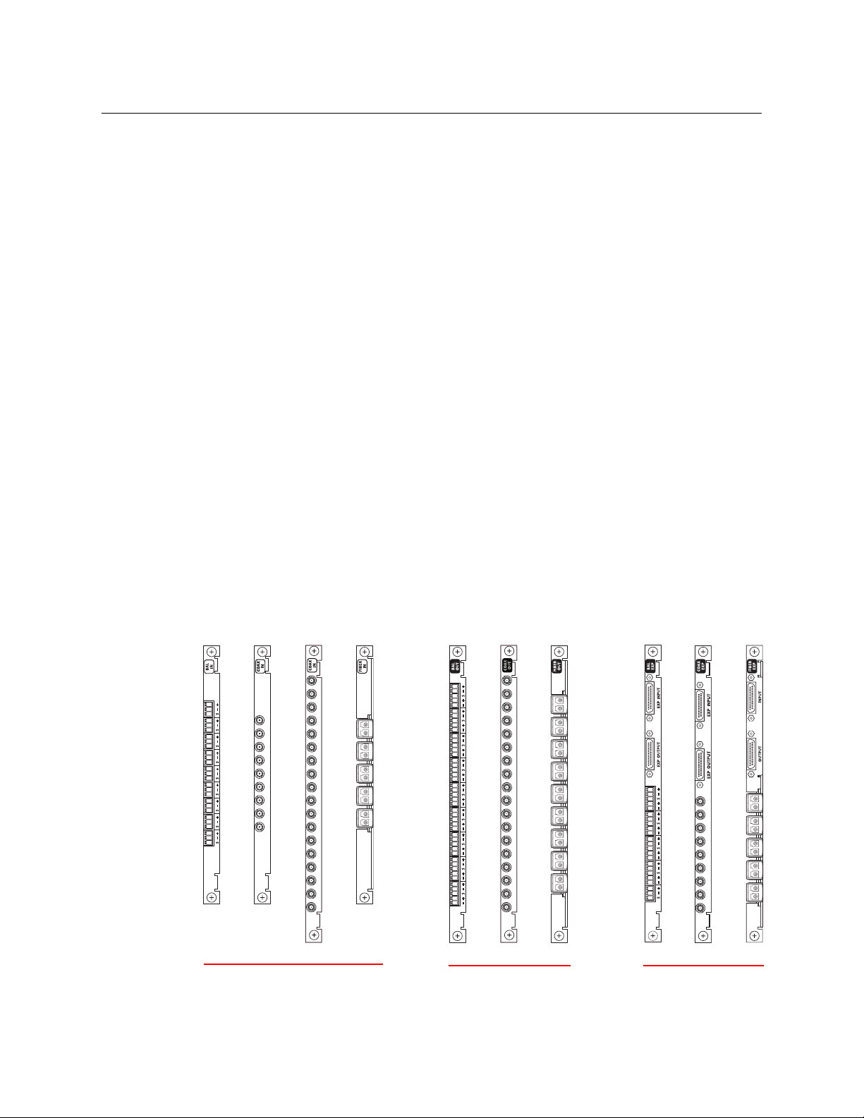
Input cards are coupled with input backplane connector modules (or backplanes, for brevity).
Output cards are coupled with output backplanes. Backplanes typically have coax (DIN 1.0/2.3)
connectors or fiber optic (SFP) connectors. (Balanced AES modules use WECO quick-release
connectors.):
2
Page 11

DHP
Reference Manual
For routers other than the NV8140, Input backplane modules each have 9 connectors. Output
backplane modules each have 18 connectors. Expansion output backplane modules (only for
the NV8576-Plus) have 9 connectors and two 28-pin expansion ports.
For the NV8140, input backplanes for the NV8140 have 18 connectors.
Standard Cards
Standard input cards use all 9 connectors of the backplane modules. Standard output cards use
all 18 connectors of the backplane modules.
Disembedder and Embedder Cards
For routers other than the NV8140, hybrid disembedder (input) cards use 8 of the 9 connectors.
The 9th connector is not used. Hybrid embedder (output) cards use 16 of the 18 connectors. The
9th and 18th connectors are not used.
For the NV8140, hybrid disembedder (input) cards use 16 of their 18 connectors. The 9th and
18th connectors are not used.
Hybrid expansion embedder (output) cards use 8 of the 9 connectors.
There are no video ports or audio ports associated with the unused connectors.
MADI Cards
(MADI cards are also known as 3Gig/TDM cards.)
For routers other than the NV8140, hybrid MADI input cards use the first 8 connectors for video
input and use the 9th connector for MADI input (up to 64 channels). Hybrid MADI output cards
use connectors 1–8 and 10–17 for video output and use the 9th and 18th connectors for MADI
output (56 or 64 channels each).
These MADI input cards have 64 audio ports. The remaining 80 ports of the card’s port space are
unused.
For the NV8140, hybrid MADI input cards use connectors 1–8 and 10–17 for video input and use
the 9th and 18th connectors for MADI input (up to 64 channels each).
These MADI input cards have 128 audio ports. The remaining 160 ports of the card’s port space are
unused.
Hybrid MADI output cards use connectors 1–8 and 10–17 for video output and use the 9th and
18th connectors for MADI output (56 or 64 channels each).
Hybrid expansion MADI output cards use the first 8 connectors for video output and use the 9th
connector for MADI output (56 or 64 channels).
MADI output cards have 128 audio ports. The remaining 160 ports of the card’s port space are
unused.
Expansion Cabling for the NV8576-Plus
The expanded NV8576-Plus router comprises two interconnected router frames. The frames use
expansion cards and expansion backplane modules. Expansion output backplanes have 9 connectors and two 28-pin expansion connectors. Cables connect the 2 router frames on the expansion
connectors.
3
Page 12
Introduction
Control System
Software
DHP
Hybrid
Router
NV9000
Std In
Std Out
Std In
Std Out
Std Out
Std In
DIS
DIS
DIS
Std In
EMB
Std Out
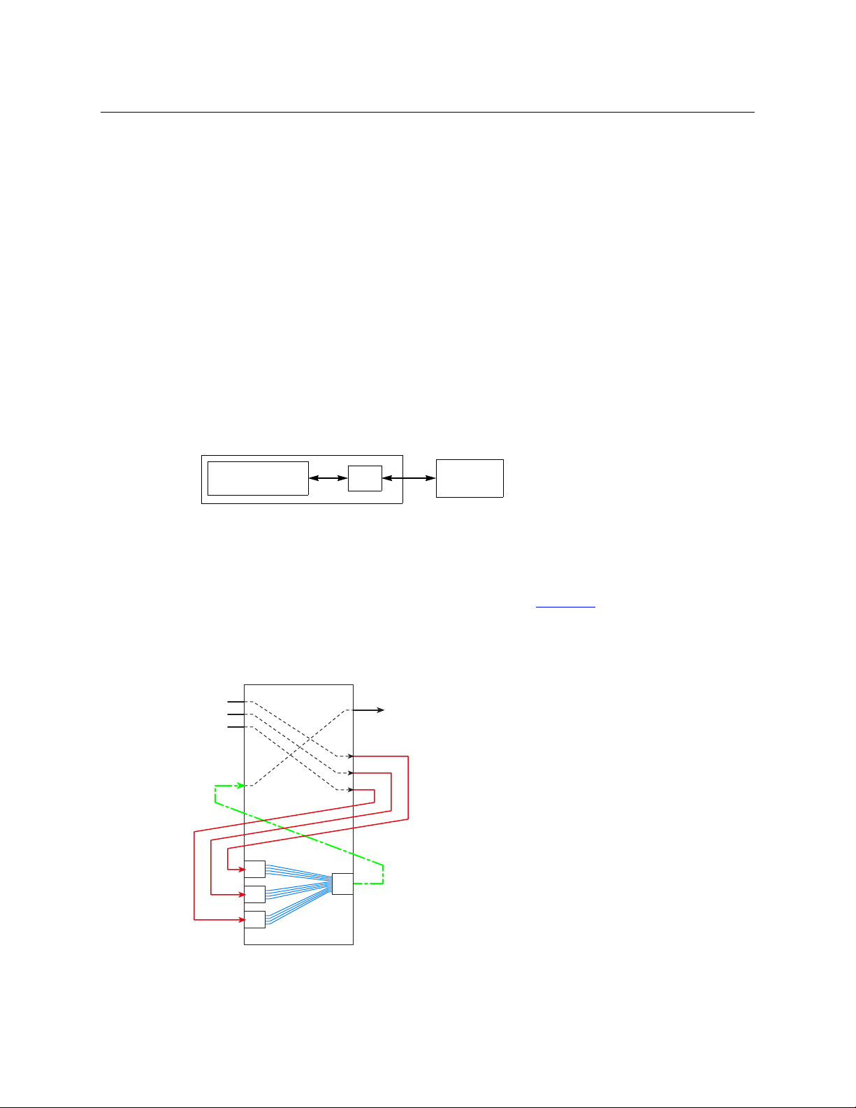
This scenario combines audio from 3 separate standard
inputs and routes the video from one of the inputs with
the combined audio on a standard output.
A disembedder port is required for each standard input
port from which audio is to be extracted. An embedder
port is required for the output that is to receive the
recombined audio.
Further, an additional standard output port is required
for each standard input port from which audio is to be
extracted. An additional standard input port is also
required for the output that is to receive the recombined
audio.
The DHP service routes the signals through a pool of
available hybrid cards internally. External cabling is
required for every DHP path.
DHP Summary
Expansion output cards provide 9 outputs. Expansion output backplanes have 9 connectors and
two 28-pin expansion connectors. Expansion filler cards provide no outputs, but support the
expansion connections. Cables connect the 2 router frames on the expansion connectors.
DHP Summary
DHP (dynamic hybrid pathfinding) allows the NV8500 router to perform hybrid routing with
relatively few hybrid cards. With DHP, the router passes standard inputs through an internal pool
of hybrid disembedder cards and embedder cards after which the audio from the standard
inputs can be recombined and re-embedded on output.
The point of DHP is that it allows you to populate the router with many relatively inexpensive
standard I/O cards and a few hybrid cards and still have the benefits of hybrid routing (that is, to
allow audio from standard inputs to be disembedded and re-embedded for standard outputs,
all within the router).
DHP is a service that resides in the NV9000. The NV9000 control software treats the DHP service
as if it were a hybrid router.
4
The DHP service then communicates with the router directly. All takes to a hybrid router go
through the DHP service, transparently. All status from the router also goes through the DHP
service.
DHP is licensed software (EC9540) that ships with the NV9000. The purchase of the license
allows you to activate the DHP service in the NV9000. See Activation
If you have an older version of the NV9000 software that does not include DHP, you will need
on page 7.
to obtain an updated version of the NV9000 software.
Figure 1-1 shows a fairly typical route using DHP:
Fig. 1-1: DHP Scenario — Recombining Audio from Standard Input
Page 13
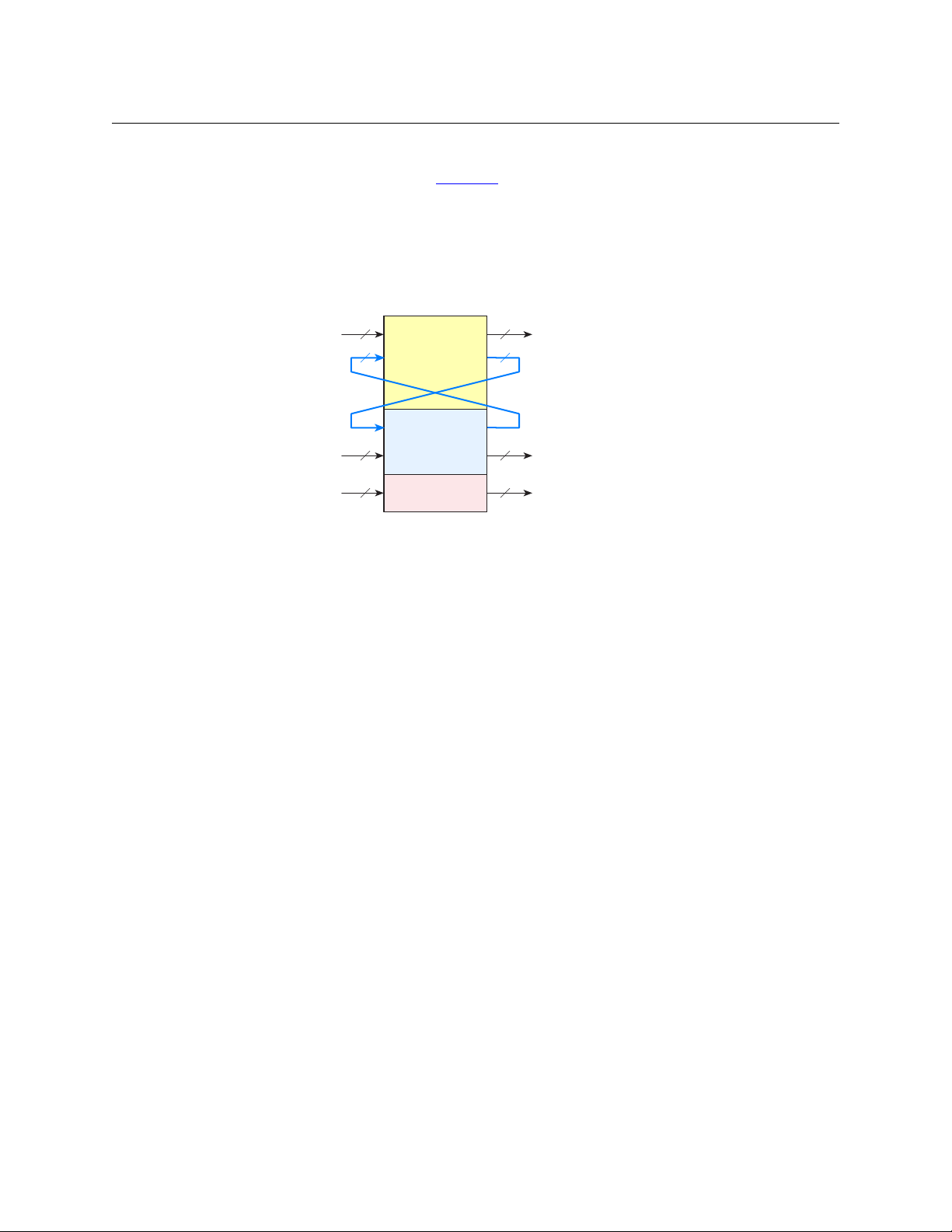
DHP
NV8500 Router
Standard Video
(with or without
embedded audio)
AES
Hybrid
Standard Video In Standard Video Out
AES In AES Out
Hybrid In Hybrid Out
DHP Links DHP Links
External cabling is required
for every DHP path.
Reference Manual
This is only one of a few dozen DHP scenarios. Other scenarios involve MADI inputs and outputs
and AES inputs and outputs. See Examples
on page 24 for a discussion of DHP scenarios.
Preliminary DHP Analysis
In the analysis of your system, you should determine the number of inputs and outputs of each
type:
Fig. 1-2: DHP Links
This evaluation includes the number of standard inputs and standard outputs, the number of
hybrid inputs and outputs, and the number of AES inputs and outputs.
If your router is to perform DHP, you will also need the size of the DHP pool (or DHP “core”), i.e,
the number of DHP links required by your router. This number might be difficult to determine.
Keep in mind that the DHP links are dedicated disembedders and re-embedders and are not to
be considered inputs and outputs. There are several factors to consider.
These are two of the factors:
1 The number of DHP paths that can be in use simultaneously.
2 The number of ports required for each path.
As stated earlier, and illustrated in Figure 1-1, a certain number of hybrid ports and a certain
number of additional standard ports are required for each DHP path.
Potentially, 16 sources could each provide a single audio channel to an output. This would be
considered an extreme and unusual case. If all 16 audio channels come from a single source,
DHP is not used for that route. Thus, the minimum number of sources for DHP is 2 and the
maximum is 16. The number of destinations for DHP is always 1.
You need to determine the average number of ports among all the DHP paths in use simultaneously. The average is, of course, somewhere between 2 and 16, probably very close to 2.
Thus, letting ‘A’ be the average number of sources, and ‘N’ be the number of simultaneous DHP
paths,
Disembedder ports = A × N
Embedder ports = N
Additional standard input ports = N
Additional standard output ports = A × N
Note that DHP is used for disembedding and re-embedding audio. Therefore the hybrid cards
that constitute the DHP core must be one of these:
5
Page 14

Introduction
DHP Summary
8500H-IP-3G-DEM-CX (disembedding, input)
8500H-OP-3G-EMB-CX (embedding, output)
8500H-OPX-3G-EMB-CX (embedding, expansion output)
[There are no fiber-optic hybrid cards at this time.]
Note: ports belonging to the DHP core cannot be used as routable inputs or outputs. Panel
operators cannot route to them or from them directly.
Other DHP Considerations
Tielines
The NV8500 router that DHP is servicing might involve some tielines. You must identify the
inputs and outputs of all tielines in a DHP configuration (initialization) file.
Force Embedder Off
The DHP configuration allows you to specify, for some inputs, that when they are routed to
embedder outputs, the embedder is forced off (i.e, the embedder is bypassed). In such a case,
the audio from the input is kept intact and passed through the output without change. This
option is controlled by “EO” commands in DHP’s port configuration files.
It might be a point of confusion that, in MRC, there is just the opposite function: some inputs in
the router are configured to force any embedding output to use its embedder, rather then let
the router follow switching rules to determine the embedder state.
If your router uses DHP, it is imperative that you do not ever use the “force embedder ON” function in MRC.
ASI Signals
You must identify ASI inputs and ASI outputs in a DHP initialization file.
See ‘HybridPorts’ Files
on page 16 for detail.
6
Page 15

Activation
DHP Service
Chapter 2 provides detailed information about DHP.
Topics
Activation . . . . . . . . . . . . . . . . . . . . . . . . . . . . . . . . . . . . . . . . . . . . . . . . . . . . . . . . . . . . . . . . . . . . . . . . . . . . . . . . . 7
Definitions . . . . . . . . . . . . . . . . . . . . . . . . . . . . . . . . . . . . . . . . . . . . . . . . . . . . . . . . . . . . . . . . . . . . . . . . . . . . . . . . 8
Configuration . . . . . . . . . . . . . . . . . . . . . . . . . . . . . . . . . . . . . . . . . . . . . . . . . . . . . . . . . . . . . . . . . . . . . . . . . . . . . 9
Configuration Process . . . . . . . . . . . . . . . . . . . . . . . . . . . . . . . . . . . . . . . . . . . . . . . . . . . . . . . . . . . . . . . . . . . . 10
DHP Features . . . . . . . . . . . . . . . . . . . . . . . . . . . . . . . . . . . . . . . . . . . . . . . . . . . . . . . . . . . . . . . . . . . . . . . . . . . . . 23
Examples . . . . . . . . . . . . . . . . . . . . . . . . . . . . . . . . . . . . . . . . . . . . . . . . . . . . . . . . . . . . . . . . . . . . . . . . . . . . . . . . . 24
Notes . . . . . . . . . . . . . . . . . . . . . . . . . . . . . . . . . . . . . . . . . . . . . . . . . . . . . . . . . . . . . . . . . . . . . . . . . . . . . . . . . . . . . 34
DHP is licensed software (EC9540) that ships with the NV9000. The purchase of the license
allows you to activate the DHP service in the NV9000.
Follow these steps to activate the DHP service:
1 Obtain the NV9000 Control System CD from Miranda (GVD). This CD contains one or more
activation programs depending on which licenses you have purchased.
2 Copy the DHP activation file (presently SV1062-01.exe) from the CD to a USB drive.
3 Connect a keyboard, mouse, and monitor to the NV9000 frame.
4 Login to the NV9000. The default username is
ware
.
5 Insert the USB drive into a free USB slot of the NV9000.
6 When the USB drive window appears, double-click the DHP activation file. The activation
program takes no more than a second to finish.
7 Remove the USB drive from the NV9000.
It might be convenient to activate all the services you have purchased at this time, if you
have purchased more than one. Just copy all your service activation programs to the USB
drive and run each one individually on the NV9000.
If you have an older version of the NV9000 software that does not include DHP, you will
need to obtain an updated version of the NV9000 software.
Repeat the activation process for each NV9000 that is to use DHP.
(You will have to log in again later to install the DHP configuration files. See Initialization—the
Configuration Files on page 13)
envyadmin and the default password is soft-
7
Page 16

DHP Service
Definitions
Definitions
Standard card Standard input or output card. Standard input or output is video
(3Gig, HD, or SD) with or without embedded audio. No disembedding or embedding occurs. Using standard cards only, the signal
passes unchanged. through the router.
Standard input card 8500-3GIG-IN-COAX
8500-HD-IN-COAX
8144-3GIG-IN-COAX
8144-HD-IN-COAX
8500-3GIG-IN-FIBER
Standard output card 8500-3GIG-OUT-COAX
8500-3GIG-OUT-COAX-EXP (for expanded routers)
8500-HD-OUT-COAX
8500-HD-OUT-COAX-EXP (for expanded routers)
8144-3GIG-OUT-COAX
8144-HD-OUT-COAX
8500-3GIG-IN-FIBER
8500-3GIG-OUT-FIBER
8500-3GIG-OUT-FIBER-EXP (for expanded routers)
Hybrid cards Hybrid cards are those that receive or transmit both video and
audio signals.
MADI card
MADI input card 8500H-IP-TDM-CX
MADI output card 8500H-OP-3G-TDM-CX
Disembedder card 8500H-IP-3G-DEM-CX
Embedder card 8500H-OP-3G-EMB-CX
Well-known ports A list of Ethernet port numbers that are used globally and are
Audio shuffling The concept of recombining audio from several inputs and
Force embedder off Under normal circumstances, the embedder of a router output is
1
MADI input or output card. The MADI ports support 64 TDM audio
channels at 48.000 kHz. (The input cards and the expansion output
card have 8 ports of standard video and one MADI input port). The
MADI output card has 16 video ports and 2 MADI ports.
8500H-OPX-3G-TDM-CX (for expanded routers)
8500H-OPX-3G-EMB-CX (for expanded routers)
registered with the IANA (Internet Assigned Numbers Authority)
http://www.iana.org/assignments/port-numbers
embedding it in one (or more) outputs.
enabled or disabled automatically according to internal switching
rules. It is possible in DHP for router inputs to be configured so that
they force the embedder to be bypassed.
1. MADI input rates (and number of channels) are determined by the actual MADI input stream. The MADI
output rate is exactly 48.0 kHz (samples per second). MADI output supports either 56 or 64 channels, according to a DIP switch setting.
8
Page 17

Tieline A connection between the output of one router and the input of
Configuration
As a service, DHP interprets take commands from the NV9000 and calculates routes that require
disembedded and re-embedded audio, and relays appropriate commands to the router. DHP
manages a pool of DHP ports that we call the DHP core. DHP also determines whether the route
requires use of the DHP core. A case where it does not require the core is a take from a standard
input to a standard output.
There are several steps in configuring DHP. These involve MRC, NV9000-SE Utilities (and your
NV9000 configuration) and DHP configuration files.
The order in which you perform the configuration steps is not critical as long as you perform all
the configuration tasks and have valid DHP configuration files installed before you restart your
NV9000 with DHP active.
There is no feedback that can tell you whether DHP is active and running properly, except that
DHP will not work if you have, for example, an improper DHP configuration file.
If you are using the NV9000 Web Suite to monitor DHP, and DHP is not operating, the DHP pages
will “freeze” and display stale data. The web suite has no failure report.
DHP
Reference Manual
another router (or possibly of the same router). A multi-hop tieline
is one that involves connections among more than two routers.
Warnings
If you are adding DHP to an existing router, save your existing configuration before doing so. If
you ever decide to stop using DHP, your router will need a non-DHP configuration to operate.
Do not restart your NV9000 without correct DHP configuration files. DHP might fail to start if it
detects errors in its configuration files.
Assumptions made here: your NV9000 is configured and is communicating with the router that
is to use DHP. This document does not address NV9000 configuration apart from the requirements for DHP.
Summary
This is a summary of the DHP configuration steps. Details follow.
1 Following your DHP analysis, populate the router with cards belonging to the DHP core.
Make notes about what you have done.
2 In MRC, define or redefine router partitions for the router.
3 In MRC, specify or re-specify the card types for all slots of the router.
4In MRC, ensure that no router input has its “force embedder on” attribute set true.
5 In NV9000-SE Utilities
a Make the NV9000 communicate with DHP (instead of the router)
b Make DHP communicate with the router’s control card(s).
6 In NotePad or a similar tool, write the DHP configuration files. Verify that they are correct and
save them in the folder
C:\nvision of the NV9000 system controller(s).
9
Page 18
DHP Service
Configuration Process
7 In NV9000-SE Utilities
a Ensure that a level set exists that includes all audio levels in use.
b Explicitly define all audio levels for standard inputs and outputs that can be switched
using DHP. [For standard I/O that will never be switched by DHP, this is not necessary.]
8 In NV9000-SE Utilities, if your router has MADI ports
a Add 40,000 to any and all MADI port numbers. (DHP requires this.)
b Add 40,000 to the audio matrix size.
9 In NV9000-SE Utilities, clear the DHP portion of the router’s crosspoint matrix.
10 Remove any previously defined sources and destinations from the DHP core portion of the
NV9000 configuration.
11 Finally, write the new configuration to the NV9000 and restart the NV9000. Then set the DHP
service to “automatic” and start the DHP service.
Configuration Process
[1] DHP Core
In your analysis of the DHP requirements of your router, you will have determined the number
and type of hybrid cards to include in the DHP core.
If you are adding DHP to an existing router, place the disembedder (input) cards and embedder
(output) cards that form the DHP core in the router. Also place the cards’ matching backplane
connector modules. The cards in the DHP core do not have to be contiguous.
If you are starting with a new unconfigured router, it is probable that the cards belonging to
your DHP core have been installed at the factory.
In either case, make sure that the cards and backplane modules are installed properly and make
careful written notes about which slots you have used for the DHP core. The port numbers for
the cards in those slots are critical to the configuration process.
10
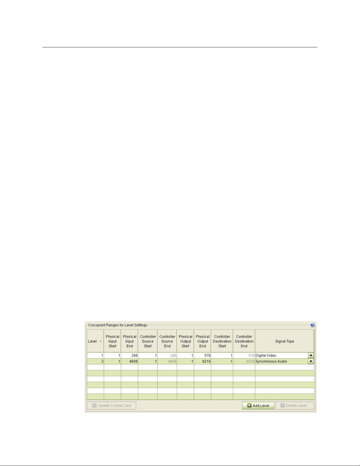
[2]
Router Levels
DHP requires that your router have exactly one ‘Digital Video’ partition and one ‘Synchronous
Audio’ partition. Partitions of other types are acceptable, such as a monitor partition. Use the
‘Router Levels’ page in MRC to define the partitions. This example is typical for an NV8280:
Fig. 2-1: Router Partitions for an NV8280 Using DHP
Page 19
Reference Manual
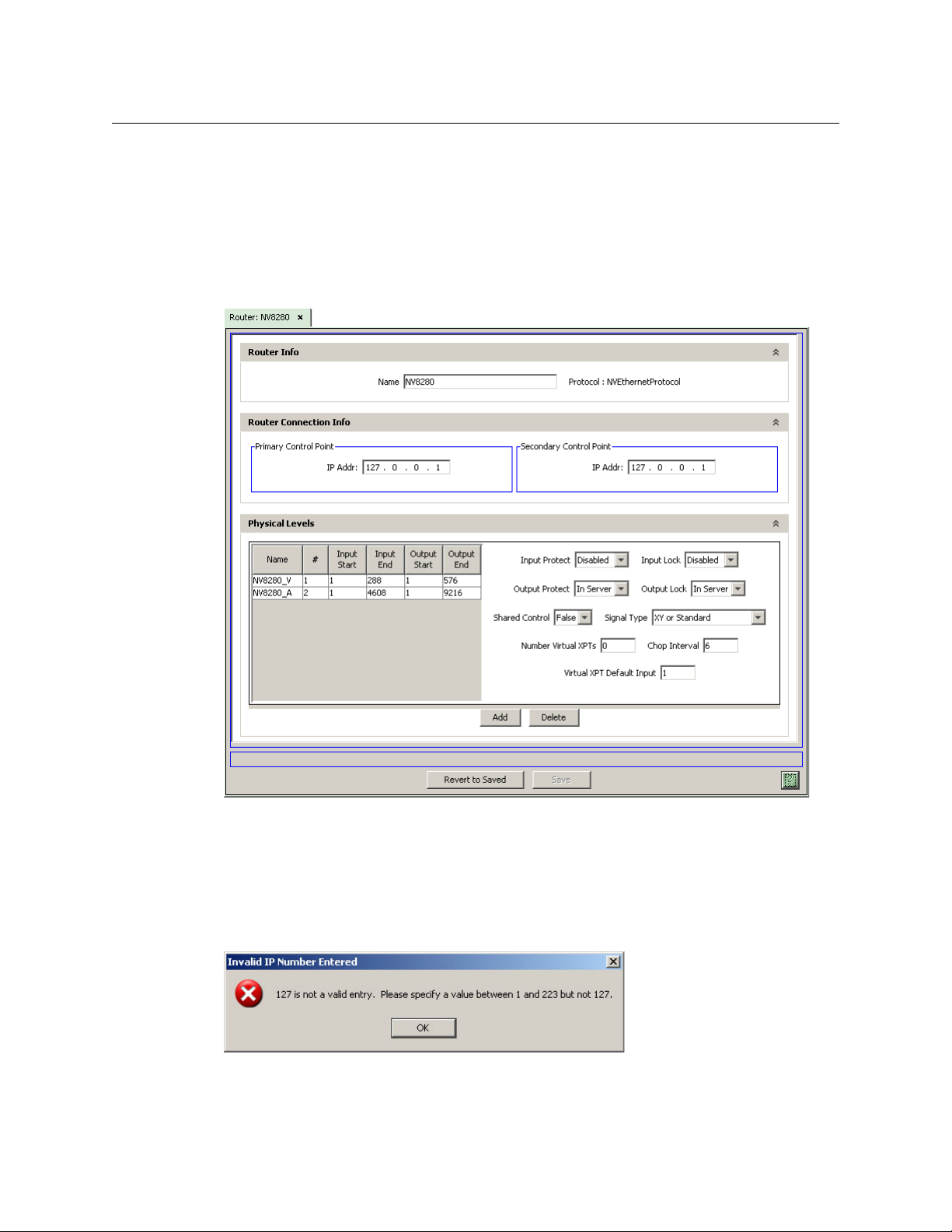
[3] NV9000-SE Configuration
If you are adding DHP to a router, you will have to change your NV9000-SE Utilities settings to
conform to what is discussed here.
DHP stands between the NV9000 control process and the router. The control process communicates with DHP as if it were the router. Therefore, in NV9000-SE Utilities, you must specify the IP
address of the router as 127.0.0.1 (which is, in a sense, the address of DHP). If you are creating a
new router definition, you will see a page similar to this:
DHP
Fig. 2-2: Router Details (NV8280 Shown)
Note: if your router has MADI cards, add 40,000 to the audio level size (i.e., to the ‘Input End’ field
and the ‘Output End’ field).
(This IP address is called a “loopback address.”)
Note that NV9000-SE Utilities will give you a warning message, because, under normal circumstances, 127.0.0.1 is an unusable address:
You can ignore this message, because the use of DHP is an exceptional circumstance.
11
Page 20
DHP Service
Configuration Process
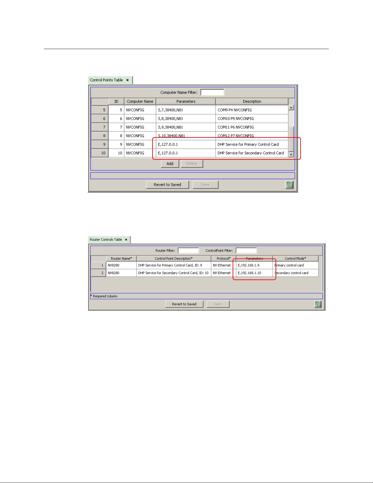
Then, in the ‘Control Points’ table (under the ‘Views’ navigation pane), change the description
field for the DHP proxy of the router: This is a sample control point table (for an NV8280):
Changing the description is not actually necessary, but very helpful.
If you are modifying an existing router definition, it is here that you would change its IP address
to 127.0.0.1.
Then, update the parameters fields in the ‘Router Controls’ table:
12
Define the parameters field as “E”, comma, and the IP address of the router control card. Doing
that lets the DHP service know the IP address of the router control card with which it is to
communicate.
(If you are modifying an existing router definition, the values you enter in the parameters field
here are what were in the parameters field of the control points table. These IP addresses will
have been initially defined in MRC.)
When there are two control cards, one primary and one secondary, only one of those control
cards is actively running. The other control card is in stand-by mode.
Similarly, when there are two control cards, the NV9000 will launch two DHP services at startup.
One of the DHP services is active and the other is stand-by (running, but idle).
At this stage, the ‘Control Points’ table is not quite finished
— you must specify the DHP ports.
Page 21

DHP
Reference Manual
DHP Ports
The DHP service relies on configuration parameters to build its internal view of the router
correctly and to act as an address translator between the control system and the actual router.
You must specify two items in the ‘Control Points’ table of NV9000-SE Utilities:
• The IP address of the DHP service. As stated previously, that is always 127.0.0.1.
• Each DHP control point needs its own port. This is designated by ‘HR:‹port›’ in the ‘Control
Points’ table entry. You may select a port from a range of unassigned “well known ports”:
9451–9499
9630–9699
9701–9746
9803–9874
If the router has primary and secondary cards, the ‘Control Points’ table will have two entries.
Append the port values to the control point parameters field(s). The entries will resemble these:
The DHP service also needs the IP addresses of the control cards with which it is communicating.
These were specified in NV9000-SE Utilities’ ‘Router Controls’ table:
2
At the end of the ‘Parameters’ field for each control point, specify the free source that DHP will
use to free DHP ports. The free source is one of the router’s video ports and it must be a disembedding port. The syntax of the free source specification is
,FS:‹port number›
Note that the DHP configuration files also use the well-known port numbers in their names.
[4]
Initialization—the Configuration Files
When the NV9000 starts up, this service creates internal maps based on configuration parameters from the NV9000 database, configuration files, and the hybrid router. This information is
combined to build a very accurate internal model of the router for the purposes of managing its
ports and channels.
After building its internal data structures, the DHP service opens a communication port with the
hybrid router and waits for the NV9000 to contact it. From the NV9000’s standpoint, the DHP
service is the hybrid router.
The service must distinguish which cards are standard cards, which cards are disembedder or
embedder cards, and which cards are MADI cards, and must know their locations within the
frame. You must make this information available in initialization files. Place the initialization files
in the folder
There are sample initialization files in that folder.
C:\nvision of the NV9000.
2. See www.iana.org/assignments/port-numbers
13
Page 22

DHP Service
Configuration Process
There are two different initialization files needed for the DHP service to operate.
where xxxx is a “well-known port” for this router that you specified earlier in the NV9000’s
‘Control Points’ table.
You must have one copy of these files for each port used. For instance, if you use ports 9476
As a reminder, these are the unassigned “well known ports”:
The
the hybrid router frame(s). The file contains commands that identify the type of card in specific
slots. The file allows one command per line. The commands are very simple.
The
bedder ports and pairs of re-embedder ports. (The DHP service to be configured on a port-byport basis.) The ports you list in the file belong to the “DHP core.”
• HybridCards_xxxx.cfg
• HybridPorts_xxxx.cfg
and 9477, you will need 4 initialization files:
HybridCards_9477.cfg, HybridPorts_9476.cfg, HybridPorts_9477.cfg.
HybridCards_9476.cfg,
9451–9499 9630–9699 9701–9746 9803–9874
HybridCards_XXXX.cfg file lets the software know what cards are located in the slots of
HybridPorts_XXXX.cfg file tells DHP the locations of the designated pairs of disem-
‘HybridCards’ Files
A ‘HybridCards’ file tells DHP what types of cards are in which slots. This is the same information
you specified in MRC in step 2-1. This information, however, resides in the NV9000 instead of the
router control card.
There are 4 commands that you can write in the file.
F ‹frame type› Acceptable
8144 — NV8144
8280 — NV8280
8576 — NV8576
8577 — NV8576-Plus
S ‹section› Acceptable values for ‹section› are
C ‹slot› ‹type› Acceptable values for ‹type› are
0 — standard card
1 — MADI card
2 — reserved for future use
3 — disembedder or embedder card
Slot numbers must be in the range supported by the router.
END Indicates the end of a section.
Note: The numbers representing card types in a ‘HybridCards’ file do not necessarily match
the numbering schemes for other software.
An F command must precede S or C commands.
An S command must precede C (card type) commands. Otherwise, DHP will not know whether
the cards defined are input cards or output cards. An END command must follow the last C
command of a section.
3
values for ‹frame type› are
IN or OUT.
14
3. DHP does not (yet) support the NV8140. You cannot choose an NV8140 in the configuration file.
Page 23

DHP
Reference Manual
You can also think of the commands as hierarchical: A frame (F) contains sections (S) and
sections contain cards (C).
The following is a small and simple example:
F 8144
S IN
C 1 0
C 2 0
C 3 3
C 4 1
END
S OUT
C 1 0
C 2 0
C 3 3
C 4 1
END
This example describes 4 input cards (in slots 1–4) and 4 output cards (in slots 1–4) in an
NV8144. In the example, the cards in the first two input slots are standard cards. The third input
slot has a disembedder card and the fourth input slot contains a MADI card.
Similarly, the cards in the first two output slots are standard cards. The third input slot has an
embedder card and the fourth output slot contains a MADI card.
Actual configuration files, of course, would be larger than this example, but just as simple.
If an NV8576-Plus has two frames, its configuration file(s) have 4 sections in order:
; Frame 1
F 8577
S IN
cards
END
S OUT
cards
END
;Frame 2
F 8577
S IN
cards
END
S OUT
cards
END
Yo u must specify the cards in ascending order of the slots.
Important: the slot ordering follows the slot labeling on the rear of the router, although
some older routers might have different labels. See Slot Numbers
Note that if DHP does not recognize the content of a line in the file, the line is treated as a
on page 51.
comment. You are free to intersperse comments throughout the configuration file.
Comments typically start with a semicolon (;) or an asterisk (*).
15
Page 24

DHP Service
Configuration Process
‘HybridPorts’ Files
The ‘HybridPorts’ files serves 3 purposes:
You can refer to the sample initialization files (located in the
controller in which DHP resides) for further information.
• It identifies the ports that form the core and their connections.
There are IN and OUT commands for the core ports.
• It identifies the ports that have certain attributes that affect DHP.
These attributes are
• Input ports that have the “force embedder” attribute (EO command).
• Output ports for which DHP emits video only (VO command).
• Input and output ports that belong to tielines (TL command).
The commands that specify these attributes (EO, VO, and TL) must appear in the HybridPorts
file after the core commands.
• It specified the maximum number of embedded audio channels in NV8500 router inputs.
Use the CHANNELS command. (The CHANNELS command can appear anywhere in the file.)
C:\nvision of the NV9000 system
Core Ports
There are two kinds of commands that you can (and must) write in the file.
IN ‹port-A› ‹type› ‹port-B›
OUT ‹port-B› ‹type› ‹port-A›
These commands must be paired. Port-A must be identical in both commands of the pair and
port-B must be identical in both commands of the pair. If there is a mismatch, DHP will return an
error report in its log file:
C:\nvision\envy\userlocal\logs\HybridSVC.log
If the error is severe, the DHP service will not run.
The ports are video port numbers in the range supported by the router. Please refer to the port
enumeration drawings, RF0272 through RF0276.
The recognized values for ‹type› are
1 — re-embedder
2 — disembedder
16
Page 25

Reference Manual
Std In
Std Out
Std In
Std Out
Std Out
Std In
DIS
DIS
EMB
port 40
port 41
port 122
port 86
port 87
port 23
An example:
This illustration shows
a One re-embedder path (green, dashed).
Each re-embedder pair describes a hybrid embedder card “tied to” a standard input card.
The single path in the example requires two commands in the file:
OUT 122 1 23 Port 122 (hybrid out) is tied to port 23 (std in).
IN 23 1 122 “1” means a re-embedder connection.
b Two disembedder paths (red, solid).
Each disembedder pair describes a standard output port “tied to” a hybrid disembedder
input card. This example has two disembedder paths, requiring 4 commands in the file:
OUT 40 2 86 Port 40 (std out) is tied to port 86 (hybrid in).
IN 86 2 40 “2” means a disembedder connection.
OUT 41 2 87 Port 41 (std out) is tied to port 87 (hybrid in).
IN 87 2 41
In general, there will be more disembedder paths than re-embedder paths.
The order in which you write the commands does not matter as long as the pairs
exist. You could group all the
OUT commands together and all the IN commands
together if it suits your purpose.
Note that if DHP does not recognize the content of a line in the file, the line is treated
as a comment. You are free to intersperse comments throughout the configuration
file. We suggest you use comments that start with a semicolon (;).
DHP
CHANNELS Command
The syntax for the “Channels” command is
CHANNELS ‹number› where 1 < ‹number› < 16
Use this command at the beginning of the ‘HybridPorts’ file to specify the maximum number of
audio channels embedded in the signals your router receives.
Caution: embedder outputs always embed 16 audio channels. If your input signal has fewer
than 16 channels, you will almost certainly want to provide generated silence for the remaining
channels at output.
17
Page 26

DHP Service
Configuration Process
Specifying a channels value allows your NV9000-SE configuration to specify only those channels
that are needed and lets DHP ignore the unspecified channels.
EO Command
This is the “Embedder Off” command. Its syntax is
Use this command to specify that for an input port, the output embedder is bypassed.
Caution: MRC lets you set a “force embedder ON” flag for any router input. For routers using
DHP, all inputs should have this attribute turned off.
Note that the sense of the EO command in DHP (force embedder off) is the opposite of the
sense in MRC (force embedder on).
For any ASI input ports, issue the EO command for the port in the HybridPorts file.
VO Command
This is the “Video Only” command. Its syntax is
Use this command to specify that an output port does not embed any audio from the router’s
audio crosspoint matrix, but emits only video (with its own embedded audio if it had any).
For any ASI output ports, issue the VO command for the port in the HybridPorts file.
EO IN ‹input-port›
VO OUT ‹output-port›
TL command
This is the “Tieline” command. Its syntax is
TL ‹port-type› ‹port› where ‹port-type› is IN or OUT
Use this command to specify that a port (an input or an output) belongs to a tieline.
Software Interface
The DHP service communicates with the hybrid router (over Ethernet) using the NVISION Router
Protocol, also known as protocol C. Its message syntax can be found in Grass Valley’s NP0016-00
protocol document.
The DHP service communicates with the NV9000 using NV9000 Ethernet Control Protocol, also
known as protocol E. Its message syntax can be found in the NP0017-00 document.
All this is internal to the NV9000 and not germane to configuration or operation.
Note that no special cabling is required.
More in NV9000-SE Utilities
Whether you are adding DHP to an existing system or you are creating a new system that has
DHP, you should observe these points in your NV9000 configuration.
18
Page 27

Reference Manual
The audio matrix here was 4608 × 9216, and still
is in reality.
[5] Audio for Standard Inputs and Outputs
You must explicitly specify the audio levels for each standard input and for each standard
output. Each standard video input can have up to 16 embedded audio channels. The same is
true for standard video output.
Define a level set that includes as many audio levels as you need. This is a typical example:
DHP
Typically, this level set would be the same level set you use for hybrid inputs and outputs.
[6]
MADI Port Numbering
For a router that has DHP and MADI cards, you must add 40,000 to all MADI port numbers.
Further, you must add 40,000 to the size of the router’s audio matrix. You must do this in
NV9000-SE Utilities, but not in MRC.
Go to the router’s detail page to change the audio matrix size. Here is the an example for an
NV8280:
19
Page 28

DHP Service
Configuration Process
Adding 40,000 in NV9000-SE Utilities does not change the port numbers themselves. It just
Although the actual matrix is still moderate in size, NV9000-SE Utilities does in fact operate
Requirements for Adding DHP to a Router
If you are creating a new DHP router and not modifying an existing router, you may skip steps 7
and 8.
[7]
Clear the Crosspoint Matrices
If you are adding DHP to a hybrid router, it is important to ensure that all inputs of the proposed
DHP core, for either core embedders or core disembedders, have all destinations cleared. To do
that, route another source, that is not part of the DHP core, to every destination port currently
using a source from the proposed DHP core inputs. If you fail to do this, the functionality of DHP
will be compromised and its resulting behavior will be unpredictable.
Use the ‘Crosspoints’ page of MRC to perform the needed routes: This is a sample of the page:
allows the MADI ports to be managed with all the non-MADI audio ports. In the example
above, the matrix is still 4608 × 9216.
as if the matrix were 44,608 × 49,216. The result is a massive performance degradation.
Fortunately, NV9000-SE Utilities is in use only for configuration and diagnostics. Neither the
NV9000 itself nor DHP suffers any performance degradation.
20
Page 29

Reference Manual
[8] NV9000 Configuration
If you are adding DHP to a hybrid router, your existing configuration might have sources and
destinations occupying positions that will be used by the proposed DHP core.
You should remove or relocate those sources and destinations
— or revise the proposed core —
so that the existing sources and destinations do not intersect with the DHP core. NV9000 panel
operators cannot use DHP core sources or destinations directly.
The DHP core comprises I/O cards that you insert in the router frame (and the cabled
connections that go with them). However, the DHP core is neither identified nor configured
in NV9000-SE Utilities.
It is possible for you to build dummy sources and destinations that describe the core into
your NV9000 configuration. Doing so might help you organize your NV9000 configuration
and might help you remember what cards and ports form the core. But remember that you
will not be able to manipulate core resources directly.
You should make sure that the dummy sources and destinations are not part of any category
and that the dummy sources and destinations are not selectable at any NV9000 control
panel.
[9]
Start the System with DHP
DHP
Write the new configuration to the NV9000 and restart the NV9000.
Then start the DHP service. The DHP service runs independently of the NV9000 software. That is,
you can start and stop the NV9000 software without effecting DHP, and vice versa. The DHP
service must be set to ‘Automatic’.
Setting the Service to Automatic
Follow these steps while logged into the NV9000:
1 Right-click the ‘NVCONFIG CONTROLLER’ icon on the desktop. (This is equivalent to ‘My
Computer’ on a regular PC desktop.)
2 Choose ‘Manage’ from the context menu.
3 When the ‘Computer Management’ window appears, choose ‘Services and Applications’.
21
Page 30

DHP Service
Configuration Process
4Right-click NvHybridSVC_(DHP) in the list of services:
5 Select ‘Properties’ in the context menu. A dialog appears:
Choose ‘Automatic’ as the startup type.
22
Page 31

DHP
Reference Manual
Starting the Service
1 If necessary, navigate again to ‘Services and Applications’.
2 Right-click NvHybridSVC_(DHP) in the list of services. Select ‘Start’ in the context menu:
Verify
Test whether, in fact, you can take a standard source to a hybrid destination or vice versa. You
can perform the take in MRC. To verify that takes are occurring properly, you will need video and
audio monitors connected to the signals you are testing.
If the take does not occur, debugging will be required. Most likely, one of the DHP configuration
files is wrong. (There is no feedback indicating DHP status.)
Correct any errors in the DHP configuration files and restart the NV9000 and restart DHP.
If DHP continues to fail, or for other failure symptoms, contact Grass Valley customer service.
DHP Features
Status
When the NV9000 requests crosspoint status, the status message from the router will actually be
received by the DHP service. DHP will translate the addresses requested to the router’s space
and send the request to the router. After receiving a response, DHP will translate back into the
NV9000’s address space and reply to the NV9000. If the NV9000 tries to obtain the status of an
area such as the embedded audio of a standard output port, it will receive what DHP “believes”
to be routed there and not necessarily what is in the TDM matrix at that point.
Status also reports whether the source or destination is a hybrid-embedder card or a hybriddisembedder card.
Take s
The service expects to receive grouped takes (meaning that all audio sources that are to be
routed to the destination be included with the video.)
Standard or Embedder Output
If the take’s destination is a standard port or an embedder port, and the service receives a take
with (1) fewer than 16 audio sources or (2) no video source, the service uses the video and audio
sources that are currently routed to the destination as the rest of the 16 audio levels and 1 video
level. It will leave these levels untouched.
23
Page 32

DHP Service
Examples
Examples
The service needs all 16 audio sources and a video source to determine whether it should route
anything to a core disembedder or to a re-embedder.
If, during a take, a disembedder or re-embedder is needed and is not available, a status value
will be sent back to the operator’s control panel letting the operator(s) know that they have
either no disembedders available or no re-embedders available.
MADI Output
MADI outputs are independent. Whatever is routed to one MADI output does not affect any
other MADI output, even when the level set of the NV9000 destination includes multiple MADI
outputs. MADI outputs that are unselected during a take remain unaffected.
There are 20 DHP scenarios, based on 4 kinds of input and 5 kinds of output. Many of the cases
are similar. Some cases are very simple and some are not. In some cases (such as standard input
to standard output) DHP actually does not use the DHP core, but simply passes the take
commands through to the router.
The 20 cases are a cross-product of 4 input situations and 5 outputs, as follows:
Input Port(s) Output Port(s)
AStandard HStandard
B Disembedder I Embedder
CMADI J MADI
D Mixed (standard, disembedder, and MADI) K Standard and MADI
L Embedder and MADI
Keep in mind that disembedder cards also emit (internally) the non-disembedded signal as
well as the video and 16 disembedded audio channels. Similarly, embedder cards also
accept video with embedded audio (in a “bypass” mode) and emits that video without
further processing.
The term MADI applies only to connectors and to external signals. Internally, the individual
MADI signals are AES
Signals processed through AES async cards cannot be part of DHP.
The DHP core is required when audio shuffling is to be performed. Audio shuffling depends
4
and are switched through a TDM “matrix.”
on the take, usually with breakaway, performed by the operator.
The following cases illustrate the different ways the DHP service handles routes.
24
4. The TDM matrix switches Dolby E, if it is present, as well as AES.
Page 33

A-H, Case 1 Standard to Standard
Std In
Std Out
Std In
Std Out
Std In
Std Out
Std Out
Std In
DIS
DIS
EMB
No audio shuffling — DHP
core not used
Audio shuffling
Std In
EMB
Std In
Std Out
Std In
Std Out
EMB
DIS
DIS
No audio shuffling — DHP
core not used
Audio shuffling
In the simple case (no audio shuffling requested), the signal will pass straight through the
router.
When audio signals are drawn from two (or more) sources, the audio must be disembedded,
combined as the operator requested, and re-embedded.
DHP
Reference Manual
A-I, Case 2
Standard to Embedder
In the simple case (no audio shuffling requested), the signal will pass straight through the
router.
When audio signals are drawn from two (or more) sources, the audio must be disembedded,
combined as the operator requested, and re-embedded.
The embedder port
The embedder port can accept video that already has embedded audio and output that
video without further processing.
— chosen by the operator — is not part of the DHP core.
25
Page 34

DHP Service
Std In
MADI Out
Std Out
DIS
Std Out
Std In
MADI Out
Std Out
DIS
Std In
DIS
Std In
MADI Out
Std Out
DIS
Std Out
Std Out
Std In
MADI Out
Std Out
Std In
DIS
Std Out
DIS
Examples
A-J, Case 3 Standard to MADI
A disembedder extracts the audio from the standard input. The audio is then distributed,
through the TDM matrix, to the necessary MADI ports.
When audio signals are drawn from two (or more) sources, two (or more) disembedder ports are
required.
Multiple MADI ports can be routed in a single take insofar as they are combined in the level set
of the (audio) destination.
The video from the standard input(s) is ignored.
A-K, Case 4
Standard to (Standard + MADI)
A disembedder extracts the audio from the standard input. The audio is then distributed,
through the TDM matrix, to the necessary MADI ports.
When audio signals are drawn from two (or more) sources, two (or more) disembedder ports are
required.
The video signal (from one of the sources) is routed through the disembedder to the specified
standard output.
26
Page 35

DHP
Std In
MADI Out
Std Out
Std Out
Std In
EMB
DIS
Std In
MADI Out
Std Out
DIS
EMB
Std Out
Std In
MADI Out
Std Out
Std In
DIS
DIS
EMB
Std Out
DIS In
Std In
Std Out
DIS
DIS
EMB
In
In
No audio shuffling — DHP
core not used
Audio shuffling
Reference Manual
It is possible for some of the audio to be sent to the standard output. After the audio is disembedded, it can be routed to any embedder output or MADI output:
A-L, Case 5
B-H, Case 6
Standard to (Embedder + MADI)
A disembedder extracts the audio from the standard input. The audio is then distributed,
through the TDM matrix, to the necessary MADI ports.
When audio signals are drawn from two (or more) sources, two (or more) disembedder ports are
required.
The video signal (from one of the sources) is routed through the disembedder to an embedder
output. The embedder port
— chosen by the operator — is not part of the DHP core.
It is possible for some of the audio to be sent to the embedder output.
Disembedder to Standard
In the simple case (no audio shuffling requested), the signal will pass straight through the
router. The audio embedded in the input is passed, without processing, to the output. (In this
situation, the DHP core is not required.)
27
Page 36

DHP Service
Out
In
EMB
DIS
DIS
In
In
EMB
DIS
Out
No audio shuffling — DHP
core not used
Audio shuffling
In
MADI Out
DIS
In
MADI Out
DIS
In
DIS
Examples
When audio signals are drawn from two (or more) sources, the audio must be disembedded,
combined as the operator requested, and re-embedded.
B-I, Case 7
B-J, Case 8
Disembedder to Embedder
In the simple case (no audio shuffling requested), the signal will pass straight through the
router.
When audio signals are drawn from two (or more) sources, the audio must be disembedded,
combined as the operator requested, and re-embedded.
The disembedder port(s) and the embedder port
— chosen by the operator — are not part of the
DHP core.
Disembedder to MADI
A disembedder extracts the audio from its own input. The audio is then distributed, through the
TDM matrix, to the necessary MADI ports.
The audio signals can be drawn from two (or more) sources.
Multiple MADI ports can be routed in a single take insofar as they are combined in the level set
of the (audio) destination.
The video from the disembedder input(s) is ignored.
The disembedder port(s)
28
— chosen by the operator — are not part of the DHP core.
Page 37

B-K, Case 9 Disembedder to (Standard + MADI)
Std Out
In
MADI Out
DIS
In
MADI Out
In DIS
Std Out
DIS
In
MADI Out
DIS
EMB
In
MADI Out
In DIS
DIS
EMB
A disembedder extracts the audio from its own input. The audio is then distributed, through the
TDM matrix, to the necessary MADI ports.
When audio signals are drawn from two (or more) sources, two (or more) disembedder ports are
required.
The video signal (from the designated source) is directed to the designated standard output.
Multiple MADI ports can be routed in a single take insofar as they are combined in the level set
of the (audio) destination.
The disembedder port(s)
— chosen by the operator — are not part of the DHP core.
DHP
Reference Manual
B-L, Case 10
Disembedder to (Embedder + MADI)
A disembedder extracts the audio from its own input. The audio is then distributed, through the
TDM matrix, to the necessary MADI ports.
When audio signals are drawn from two (or more) sources, two (or more) disembedder ports are
required.
The video signal (from the designated source) is directed to the designated embedder output.
The embedder port
Multiple MADI ports can be routed in a single take insofar as they are combined in the level set
of the (audio) destination.
The disembedder port(s) and embedder port
DHP core.
— chosen by the operator — is not part of the DHP core.
— chosen by the operator — are not part of the
29
Page 38

DHP Service
MADI In Std Out
Std In
MADI In
EMB
MADI In Std Out
Std In
EMB
MADI In
MADI In
EMB
MADI In
EMB
MADI In
MADI In
MADI Out
MADI In
MADI Out
Examples
C-H, Case 11 MADI to Standard
An embedder receives the audio from the designated MADI input port(s) through the TDM
matrix. The embedded audio is then directed to the designated standard output.
Audio signals can be drawn from two (or more) sources.
The video signal at the standard output is not changed.
C-I, Case 12
C-J, Case 13
MADI to Embedder
The designated embedder port receives the audio from the designated MADI input port(s)
through the TDM matrix.
Audio signals can be drawn from two (or more) sources.
The video signal at the embedder output is not changed.
The embedder port
— chosen by the operator — is not part of the DHP core.
MADI to MADI
The MADI ports (identified by the level set of the take’s destination) receive the audio from the
designated MADI input port(s) through the TDM matrix.
Audio signals can be drawn from two (or more) sources.
30
No video signal is involved.
Page 39

DHP
Std Out
Std In
MADI In
EMB
MADI In
MADI Out
MADI Out
MADI In Std Out
Std In
EMB
MADI In
EMB
MADI In
MADI Out
Out
MADI Out
MADI In
EMB Out
Reference Manual
Multiple MADI ports can be routed in a single take insofar as they are combined in the level set
of the (audio) destination.
C-K, Case 14
C-L, Case 15
MADI to (Standard + MADI)
The destination can include a video port, one or more embedded audio channels, and one or
more MADI ports. The embedded audio channels and the MADI ports (identified by the take’s
destination) receive the audio from the designated MADI input port(s) through the TDM matrix.
Audio signals can be drawn from two (or more) sources.
Some of the MADI inputs can be routed, through a DHP embedder, to a standard output.
The video signal at the standard output is not changed.
MADI to (Embedder + MADI)
The destination can include a video port, one or more embedded audio channels, and one or
more MADI ports. The embedded audio channels and the MADI ports (identified by the take’s
destination) receive the audio from the designated MADI input port(s) through the TDM matrix.
Audio signals can be drawn from two (or more) sources.
The video signal at the embedder port is not changed.
The embedder port
— chosen by the operator — is not part of the DHP core.
31
Page 40

DHP Service
In
Std In
Std Out
MADI In
Std Out
Std In
DIS
DIS
EMB
In
Std In
Std Out
MADI In
DIS
DIS
EMB
Examples
D-H, Case 16 Mixed to Standard
In the case of mixed input (standard, disembedder, or MADI), audio is extracted from the various
inputs according to the breakaway specified by the operator. If there are standard inputs among
the mix, a disembedder in the DHP core is required to extract the audio from each one.
The audio from the various sources is re-embedded and sent to the designated standard
output.
(Because the embedder card supports 16 audio channels, this scenario could potentially have
up to 16 input sources of various kinds.)
D-I, Case 17
Mixed to Embedder
In the case of mixed input (standard, disembedder, or MADI), audio is extracted from the various
inputs according to the breakaway specified by the operator. If there are standard inputs among
the mix, a disembedder in the DHP core is required to extract the audio from each one.
The audio from the various sources is re-embedded by the designated embedder output. The
embedder port
(Because the embedder card supports 16 audio channels, this scenario could potentially have
up to 16 input sources of various kinds.)
— chosen by the operator — is not part of the DHP core.
32
Page 41

D-J, Case 18 Mixed to MADI
In
Std In
Std Out
MADI In
DIS
DIS
MADI Out
MADI Out
In
Std In
Std Out
MADI In
Std Out
Std In
DIS
DIS
EMB
In the case of mixed input (standard, disembedder, or MADI), audio is extracted from the various
inputs according to the breakaway specified by the operator. If there are standard inputs among
the mix, a disembedder in the DHP core is required to extract the audio from each one.
The audio from the various sources is routed through the TDM matrix to the MADI ports designated by the operator.
(Because the embedder card supports 16 audio channels, this scenario could potentially have
up to 16 input sources of various kinds.)
Multiple MADI ports can be routed in a single take insofar as they are combined in the level set
of the (audio) destination.
DHP
Reference Manual
D-K, Case 19
Mixed to (Standard + MADI)
In the case of mixed input (standard, disembedder, or MADI), audio is extracted from the various
inputs according to the breakaway specified by the operator. If there are standard inputs among
the mix, a disembedder in the DHP core is required to extract the audio from each one.
The audio from the various sources is routed through the TDM matrix to the ports designated by
the operator. Some of the audio can be directed to MADI output and some to the standard
output, depending on the level set of the destination.
(Because the embedder card supports 16 audio channels, this scenario could potentially have
up to 16 input sources of various kinds.)
Multiple MADI ports can be routed in a single take insofar as they are combined in the level set
of the (audio) destination.
33
Page 42

DHP Service
MADI Out
In
Std In
Std Out
MADI In
DIS
EMB
DIS
Out
Notes
The video signal can come from any standard input or disembedder input. It is the operator who
designates the source of the video. The video is routed through an embedder port to the standard output chosen by the operator.
D-L, Case 20
Mixed to (Embedder + MADI)
In the case of mixed input (standard, disembedder, or MADI), audio is extracted from the various
inputs according to the breakaway specified by the operator. If there are standard inputs among
the mix, a disembedder in the DHP core is required to extract the audio from each one.
The audio from the various sources is routed through the TDM matrix to the ports designated by
the operator. Some of the audio can be directed to MADI output and some to the embedder
output, depending on the level set of the destination.
(Because the embedder card supports 16 audio channels, this scenario could potentially have
up to 16 input sources of various kinds.)
The video signal can come from any standard input or disembedder input. It is the operator who
designates the source of the video. The video is directed to the embedder port chosen by the
operator. That port is not part of the DHP core.
Notes
Embedders and Disembedders
The DHP service keeps an internal list of which devices are already being disembedded so that it
does not use up more than one disembedder for that device. It will not free the disembedder
until none of its channels are being routed to destinations.
To clear a disembedder forcibly, an operator must route a new source to the disembedder’s
current destination(s). This action is tricky because there might be several destinations for each
channel. (Clearing a disembedder might be hard for an operator to accomplish because it is not
always obvious to what current destinations a disembedder is routed and the operator might
not be able to tell where a particular disembedder source is routed). As long as one audio
channel remains routed
The web suite does not have commands that clear the disembedders and embedders used by
the DHP core.
5. The channel is still listed in the disembedder data structures as having a destination
34
5
to a destination, the disembedder will not be free to use.
Page 43

DHP
Reference Manual
The DHP service also keeps an internal list of which devices are already being re-embedded so
that if anyone would like to route that combination to another destination it will use the already
assembled source.
To clear a re-embedder, route a new source to its ultimate destination.
If a disembedder is not available, or if a re-embedder is not available, the error status is returned
in the router’s response to the ‘Take’ command. The response goes back to the NV9000 and
then, in some form, to the operator’s panel.
Product Limitations
The DHP service currently does not understand what to do with AES asynchronous cards. (It is
best to leave this area of the router as a blank in its configuration.)
The DHP service knows only of cards listed in
internal matrix based on this information. If a card is removed or replaced with a different type,
this file will need to be updated.
The
HybridPorts_xxxx.cfg file is similar. DHP knows only of the port pairs defined in this file.
If either of the configuration files has changed, the DHP service must be restarted. Follow these
steps while logged into the NV9000:
1 Right-click the ‘NVCONFIG CONTROLLER’ icon on the desktop. (This is equivalent to ‘My
Computer’ on a regular PC desktop.)
2 Choose ‘Manage’ from the context menu.
3 When the ‘Computer Management’ window appears, choose ‘Services and Applications’.
4Right-click Nv
HybridSVC_(DHP) in the list of services. Select ‘Restart’ in the context menu:
HybridCards_xxxx.cfg. It will create a sparse
Be sure to update the configuration (i.e., initialization) files on both NV9000 system controllers if
you have a redundant NV9000 system.
Architectural Defects
Even without DHP, it is possible for NV9000 panels to present false status. That is because the
NV9000 gives status before it performs router operation such as a take. If the operation fails, the
false status remains for a significant time (several seconds to a minute or more) before the
NV9000 recognizes the true status of the router.
DHP was intended to be transparent. It is, perhaps, until a failure occurs. With DHP, take failures
are possible, because DHP relies on a pool of resources that can become depleted.
35
Page 44

DHP Service
Notes
36
Page 45

Summary
NV9000 Web Suite
Chapter 3 provides detailed information about the DHP status portion of the NV9000 Web Suite.
Topics
Summary . . . . . . . . . . . . . . . . . . . . . . . . . . . . . . . . . . . . . . . . . . . . . . . . . . . . . . . . . . . . . . . . . . . . . . . . . . . . . . . . 37
DHP Pages . . . . . . . . . . . . . . . . . . . . . . . . . . . . . . . . . . . . . . . . . . . . . . . . . . . . . . . . . . . . . . . . . . . . . . . . . . . . . . . 39
Sample NV9000 Data . . . . . . . . . . . . . . . . . . . . . . . . . . . . . . . . . . . . . . . . . . . . . . . . . . . . . . . . . . . . . . . . . . . . . 46
The NV9000 Web Suite is a browser-based application that provides status for several NV9000
functions (DHP, tIelines and crosspoints) and allows users to perfom takes, breakaway, levelmapping, locks, and protects.
Specifically applicable here are the web suite’s pages for DHP status.
Note however that the web suite does not provide any control functions for DHP.
The web suite provides a relatively simple way to view the current state of the DHP core of an
NV8500 series router. It provides data in both tabular and graphical formats.
The web suite is a browser application. Accessing the web suite depends on its location at your
facility:
• If the web suite was installed on your PC, enter “localhost” in the URL field of your browser.
• If the web suite was installed on someone else’s PC, enter the IP address of that person’s PC.
(Communicate with you system’s administrator to obtain that IP address.)
If the web suite has been set up properly, it should immediately establish communication with a
NV9000 system controller in your system. You might have to login to the web suite if you are not
already logged in. Please refer to the NV9000 Web Suite Users Guide for details.
Note:
The web suite requires a browser that supports HTML 5, such as Firefox or Chrome.
suite is also designed to operate well on hand-held devices such as iPads, ViewSonic tables,
Motorola Zoom tables and others. (If your browser does not support HTML 5, the web suite
will tell you.)
At present, the web suite provides status for only one router using DHP. The NV9000 system
controller you are monitoring must have only one DHP service running.
To use the web suite, you must have been assigned a user name and (optionally) a password.
Either you or your system’s administrator will have configured the web suite for a number of
users and for access to a specific NV9000 family system controller.
The DHP service can communicate with only one instance of the web suite. However,
multiple users can use the same instance.
1
The web
1. Internet Explorer v10 supports HTM 5.
37
Page 46

NV9000 Web Suite
Summary
After you have accessed the web suite and have chosen its DHP tab (or one of its DHP tabs if it
has more than one) you will see a window similar to the following:
Fig. 3-1: DHP Tab of the Web Suite
Within the web suite window, there are two tiers of tabbed pages. You will see two rows of
“tabs.”
The upper row of tabs selects a function within the web suite. Presently there are 5 functions in
the upper row and a sixth tab in which you can configure the web suite itself:
• DHP
The DHP pages present tables and diagrams of DHP usage. This of course is of primary concern to DHP users.
You might see the term “DHP Management.” Note however that the DHP pages are
simply status pages.
• Tielines
The tielines pages present tables and diagrams of tieline usage. In general, this tab important if your system uses tielines, and might or might not be of interest to DHP users.
• Multi-Level
The multi-level tab presents a detailed table of “crosspoint” data. Although the data are
important, they do not have a direct bearing on the use of DHP pages.
• Primary Level
The primary level presents a less detailed table of “crosspoint” data. Although the data are
important, they do not have a direct bearing on the use of DHP pages.
• Matrix View
The matrix view can be of some use to DHP users. It displays your system’s “crosspoint” data
in a grid and indicates where connections are locked and where breakaway or level-mapping occurs.
In this view, you can perform takes, locks, and protects in the matrix view and you can
release locks and protects.
38
Page 47

DHP Pages
Std Out for Disembedder 29
INA 045
Disembedder 29
Embedder 19
Legend
Internal Route
Core Cable for Disembedder
Audio Channels
INA 410
Std Out for Disembedder 28
Disembedder 28
OUTA 455
Std In for
Embedder 19
Core Cable for Embedder
DHP
Reference Manual
• Options
The ‘Options’ tab allows users (with admin privilege) to configure the web suite’s interfaces.
Those users may also create additional tabs that show different views of NV9000 data. It also
provides logging data for Grass Valley service technicians.
The second row of tabs belongs to whatever category you have selected in the upper row. For
DHP, there are 4 tabbed pages:
DHP disembedder DHP embedder
DHP re-entry DHP drawing
For information about other tabs and pages, please refer to the NV9000 Web Suite Users Guide.
The four DHP pages show information about the current state of the DHP core of a single
NV8500 series router (NV8144, NV8280, NV8576, or NV8576-Plus).
DHP does not (yet) support the NV8140.
Three of its pages present tables of DHP core data. The fourth page presents the data as a
drawing. The drawing page is a “schematic” view of the current core. The table data present
either a subset of the signal detail of the DHP core or all of it, depending on configuration of the
web suite.
The following sections describe the pages.
The examples shown in this section refer to a demonstration system. The configuration data for
that system are listed in the Sample NV9000 Data
on page 46.
Example
Figure 3-2 shows an DHP routing example for the 4 tabbed pages described in the following
sections:
Fig. 3-2: Sample DHP Route
In this example, standard source INA 410 is taken to standard destination OUTA 455 on all levels
but two. The remaining two levels (levels 3 and 4) are take from standard source INA 045. Except
for the breakaway involved, DHP would not be required. Because a breakaway occurred, the
DHP software routed INA 410 through DHP disembedder port 28 and INA 045 through DHP
disembedder port 29. The audio from these two ports are recombined in DHP embedder port
19 and forwarded, with the original video from INA 410 to standard output OUTA 455.
39
Page 48

NV9000 Web Suite
DHP Pages
DHP Disembedder
The ‘DHP Disembedder’ page shows details of the DHP core’s disembedders:
Fig. 3-3: DHP Disembedder Page
The page displays a table of disembedder ports in the DHP core, one row for each port. The
disembedder ports are identified in column 1. If a disembedder is not in use, its table row is
dimmed.
Entries in the column labeled ‘SDI’ show the name and port number of the standard video input
port connected to the disembedder port.
The entries in the columns labeled ‘Feeding 1’, ‘Feeding 2’, and so on, show output ports that are
fed by the disembedder port. (The number of “Feeding” columns is a DHP page preference.)
40
Page 49

DHP
Reference Manual
DHP Embedder
The ‘DHP Embedder’ page shows details of the DHP core’s embedders. The page displays a table
of embedder ports in the DHP core, one row for each port. The embedder ports are identified in
column 1. If an embedder is not in use, its table row is dimmed.
The table always has 16 audio columns because each audio channel of the embedder port
receives audio from some source (even if it is only silence). However, as a page preference, you
can specify the columns (levels) that are displayed. Figure 3-4 shows the left portion of the page:
Fig. 3-4: DHP Embedder Page, Left Portion
Entries in the column labeled ‘SDI’ show the name and port number of the standard input port
connected to the disembedder port that feeds the video to the embedder port.
The entries in the columns labeled ‘Audio 1’, ‘Audio 2’, and so on, show the audio channels that
are fed to the embedder port. The audio signals can come from any disembedder in the DHP
core.
The audio channels are identified by the video port names and audio port numbers assigned to
them in NV9000-SE Utilities.
41
Page 50

NV9000 Web Suite
DHP Pages
DHP Re-Entry
The ‘DHP Re-Entry’ page shows which standard video input and standard video outputs are
connected to each embedder port:
Fig. 3-5: DHP Re-Entry Page
Another way you can think of this is that the table shows the standard video connections that
use the DHP core, and which embedder card is used for each connection. The table does not
show any other information.
The page displays a table of all the embedder ports in the DHP core, one row for each port. The
embedder ports are identified in column 1. If an embedder is not in use, its table row is empty
(except for column 1).
Entries in the column labeled ‘SDI SRC’ show the name and port number of the standard input
port connected (indirectly) to the embedder port. It represents the video signal at the standard
input.
The entries in the columns labeled ‘Dest 1’, ‘Dest 2’, and so on, show output ports that are fed by
the embedder port. (As a page preference, you can specify the number of “Dest” columns to
display.) The DHP service detects when a route using the core has exactly the same sources,
video and audio, as another route through the core. It then connects the multiple outputs to the
same standard input card of the core as shown in the example following.
If the embedder card connects to more than 8 outputs, the display changes to increase the
height of the table row for that embedder and the additional outputs “wrap” around to the
column labeled ‘Dest 1’ and so on. The height of the table row will adjust to accommodate all
the destinations corresponding to that embedder port.
42
DHP Drawing
The ‘DHP Drawing’ page gives you a graphic, i.e., schematic, view of the DHP core and the
signals currently connected to the core.
It has the additional advantage of showing MADI, disembedder, and embedder connections
that are not part of the core.
Page 51

Reference Manual
This image is a sample showing some connections of the small demonstration system:
DHP
Fig. 3-6: DHP Drawing Page
Central to the page is a rectangle representing the router connected to the DHP service.
The top half of the rectangle represents standard input and output ports, some of which are part
of the DHP core.
The bottom half of the rectangle represents hybrid inputs and outputs. Hybrid I/O includes
disembedder ports, embedder ports, and MADI input or output connections.
Signal Paths
Dashed lines represent standard inputs and outputs connected to the core. For instance, in the
illustration, INA 045 is a standard input and OUTA 455 is a standard output. See the Sample
NV9000 Data, following.
Solid lines represent paths within the DHP core. Single black lines represent video with or
without embedded audio. Blue 3-line groups represent audio disembedding and re-embedding. The 3-line groups represent any number of audio channels (from 1 to 16), not just 3.
Short red lines represent connections to the disembedders and embedders of the core.
43
Page 52

NV9000 Web Suite
DHP Pages
Usage
At the left side of the page are two regions:
Also at the left side of the page are two buttons:
• Radio buttons.
The 4 radio buttons allow you to select what appears in the check boxes in the second
region. For instance, if you select the ‘Embedders’ radio button, a list of the embedders
appears in the second region.
• Check boxes.
When you check a box in this region, the drawing shows all DHP elements that relate to what
you have checked. For example, Figure 3-6, on page 43, has disembedder 19 checked. The
drawing shows the embedders, standard inputs, and standard outputs that connect to disembedder 19.
Depending on which radio button you chose, the check box list will include special check
boxes: ‘All unused disembedders’, ‘All unused embedders’, or ‘All other DHP resources’. Checking one of these boxes will result in the display of the named items.
• Select All.
This is a shortcut that checks all the check boxes in the list and causes the drawing to show
all the items corresponding to all the check boxes.
• Clear Selection.
This shortcut clears all the check boxes in the list. The result is that the drawing shows nothing (except the rectangle representing the router).
44
Page 53

DHP
Reference Manual
When you select many or all items in the check box list, the drawing shows many connections:
This kind of view has its uses, but also obscures individual connection details.
Preferences
Each of the DHP pages has several user-selectable preferences, available in the sidebar of the
web suite. Refer to the NV9000 Web Suite Users Guide for details on DHP display preferences
and DHP page configuration options.
45
Page 54

NV9000 Web Suite
Sample NV9000 Data
Sample NV9000 Data
These are the data of the NV9000 configuration from which the DHP example was taken.
Non-Core Ports
These are the ports — not in the DHP core — that are used in the examples. These were configured in NV9000-SE Utilities.
Input
These are all standard inputs, each having video and 16 audio channels.
Device HD Port Audio Ports
INA 37 37 577–592
through
INA 576 576 9201–9216
There are also MADI ports 1–64 from input card 1
Output
These are all standard outputs, each having video and 16 audio channels\.
Device HD Port Audio Ports
OUTA 37 37 577–592
through
OUTA 576 576 9201–9216
There are also MADI ports 1–64 on output card 1.
DHP Core Ports
These are the ports of the DHP core, as configured in the HybridPorts_xxxx file (one of the
two DHP configuration files).
Re-embedders tied to Standard Inputs
Embedder Port Standard Input Port
19 1
20 2
21 3
22 4
23 5
24 6
25 7
26 8
28 10
29 11
30 12
31 13
32 14
33 15
34 16
35 17
46
Page 55

DHP
Reference Manual
(These embedder outputs are all on output card 2. Note that the ports that would be numbered
27 and 36 do not exist.)
Disembedders tied to Standard Outputs
Disembedder Port Standard Output Port
28 1
29 2
30 3
31 4
32 5
33 6
34 7
47
Page 56

NV9000 Web Suite
Sample NV9000 Data
48
Page 57

Parts
Misc. Topics
Chapter 4 provides additional information.
Topics
Parts . . . . . . . . . . . . . . . . . . . . . . . . . . . . . . . . . . . . . . . . . . . . . . . . . . . . . . . . . . . . . . . . . . . . . . . . . . . . . . . . . . . . . 49
Slot Numbers . . . . . . . . . . . . . . . . . . . . . . . . . . . . . . . . . . . . . . . . . . . . . . . . . . . . . . . . . . . . . . . . . . . . . . . . . . . . . 51
I/O Cards
Order Code Description
8144-3GIG-IN-COAX
8144-3GIG-OUT-COAX
8144-HD-IN-COAX
8144-HD-OUT-COAX
8500-3GIG-IN-COAX
8500-3GIG-IN-FIBER
8500-3GIG-OUT-COAX
8500-3GIG-OUT-COAX-EXP
8500-3GIG-OUT-FIBER
8500-3GIG-OUT-FIBER-EXP
8500-AES-ASYNC-IN
8500-AES-ASYNC-OUT
8500-AES-ASYNC-OUT-EXP
8500-HD-IN-COAX
8500-HD-OUT-COAX
8500-HD-OUT-COAX-EXP
Standard 9-input card, 3Gig, HD, or SD, for use with coax connectors for
the NV8144.
Standard 18-output card, 3Gig, HD, or SD, for use with coax connectors
for the NV8144.
Standard 9-input card, HD or SD, for use with coax connectors for the
NV8144.
Standard 18-output card, HD or SD, for use with coax connectors for the
NV8144.
Standard 9-input card, 3Gig, HD, or SD, for use with coax connectors.
Standard 9-input card, 3Gig, HD, or SD, for use with SFP connectors.
Standard 18-output card, 3Gig, HD, or SD, for use with coax connectors.
Standard 8-output expansion card, 3Gig, HD, or SD, for use with coax
connectors.
Standard 18-output card, 3Gig, HD, or SD, for use with SFP connectors.
Standard 8-output expansion card, 3Gig, HD, or SD, for use with SFP connectors.
Standard 9-input card, AES async, for use with coax connectors.
Standard 18-output card, AES async, for use with coax connectors.
Standard 8-output expansion card, AES async, for use with coax connectors.
Standard 9-input card, HD or SD, for use with coax connectors.
Standard 18-input card (HD or SD) for use with coax connectors.
Standard 9-output expansion card (HD or SD) for use with coax connectors.
49
Page 58

Misc. Topics
Parts
Order Code Description
8500H-IP-3G-DEM-CX
8500H-IP-3G-FBR
8500H-IP-3G-TDM-CX
8500H-OP-3G-EMB-CX
8500H-OP-3G-FBR
8500H-OP-3G-TDM-CX
8500H-OPX-3G-EMB-CX
8500H-OPX-3G-FBR
8500H-OPX-3G-TDM-CX
Hybrid 8-input disembedder card (3Gig, HD, or SD) for use with coax connectors.
Hybrid 8-input disembedder card (3Gig, HD, or SD) for use with SFP connectors.
Hybrid MADI input card, 8 video inputs (3Gig, HD, or SD) and 1 MADI
input, for use with coax connectors.
Hybrid 16-output embedder card (3Gig, HD, or SD) for use with coax connectors.
Hybrid 16-output embedder card (3Gig, HD, or SD) for use with SFP connectors.
Hybrid MADI card, 16 video outputs (3Gig, HD, or SD) and 2 MADI outputs, for use with coax connectors.
Hybrid embedder expansion output card, 8 outputs (3Gig, HD, or SD) for
use with coax connectors.
Hybrid embedder expansion output card, 8 outputs (3Gig, HD, or SD) for
use with SFP connectors.
Hybrid MADI expansion output card, 8 video outputs (3Gig, HD, or SD)
and 1 MADI output, for use with coax connectors.
I/O Backplane Connector Modules
Order Code Description
IO8500-3GIG-IN-COAX
IO8500-3GIG-IN-FIBER
IO8500-3GIG-IN-SFP
IO8500-3GIG-OUT-COAX
IO8500-3GIG-OUT-COAX-EXP
IO8500-3GIG-OUT-FIBER
IO8500-3GIG-OUT-FIBER-EXP
IO8500-3GIG-OUT-SFP
IO8500-AES-IN-BAL
IO8500-AES-OUT-BAL
IO8500-AES-OUT-BAL-EXP
IO8500-IP-3G-CWDM-SFP
IO8500-OP-3G-CWDM-SFP-27/29
IO8500-OP-3G-CWDM-SFP-31/33
IO8500-OP-3G-CWDM-SFP-35/37
IO8500-OP-3G-CWDM-SFP-39/41
IO8500-OP-3G-CWDM-SFP-43/45
IO8500-OP-3G-CWDM-SFP-47/49
IO8500-OP-3G-CWDM-SFP-51/53
8500 9IN 3GIG COAX Rear
8500 9IN 3GIG FIBER Rear
8500 2IN Optical SFP Module
8500 18OUT 3GIG COAX Rear
8500 9OUT W/EXP 3GIG COAX Rear
8500 18OUT 3GIG FIBER Rear
8500 9OUT W/EXP FIBER Rear
8500 2OUT Optical SFP Module
8500 9in AES BAL Rear
8500 18out AES BAL Rear
8500 9out w/EXP AES BAL rear
8500 2IN CWDM SFP
8500 2OUT 1271/1291nm, SFP
8500 2OUT 1311/1331nm,SFP
8500 2OUT 1351/1371nm, SFP
8500 2OUT 1391/1411nm, SFP
8500 2OUT 1431/1451nm, SFP
8500 2OUT 1471/1491nm, SFP
8500 2OUT 1511/1531nm, SFP
50
Page 59

Order Code Description
7 5 43218615 13 12 11 10 916 14 7 5 4 3 2 186
OUTPUTSINPUTS
(Viewed from the
rear of the frame)
7 5 43218 6 15 13 12 11 10 916 14 7 5 4 3 2 186
OUTPUTSINPUTS
(Viewed from the
rear of the frame)
31 29 28 27 26 2532 30 15 13 12 11 10 916 1423 21 20 19 18 1724 22 7 5 4 3 2 186
31 29 28 27 26 2532 30 15 13 12 11 10 916 1423 21 20 19 18 1724 22 7 5 4 3 2 186
OUTPUTS
INPUTS
(Viewed from the
rear of the frame)
IO8500-OP-3G-CWDM-SFP-55/57
IO8500-OP-3G-CWDM-SFP-59/61
IO8500-SD-HD-IN-COAX
IO8500-SD-HD-OUT-COAX
IO8500-SD-HD-OUT-COAX-EXP
8500 2OUT 1551/1571nm,SFP
8500 2OUT 1591/1611nm, SFP
8500 9IN SD/HD COAX Rear
8500 18OUT SD/HD COAX Rear
8500 9OUT W/EXP HD COAX REAR
These are the hybrid disembedder and embedder cards:
8500H-IP-3G-DEM-CX (Disembedding)
8500H-OP-3G-EMB-CX (Embedding)
8500H-OPX-3G-EMB-CX (Embedding, expansion)
These are the hybrid MADI cards:
8500H-IP-3G-TDM-CX Input
8500H-OP-3G-TDM-CX Output
8500H-OPX-3G-TDM-CX Output, expansion
There are no fiber hybrid cards at this time.
DHP
Reference Manual
Slot Numbers
It is important use the correct slot numbers when preparing DHP’s Hybridcards_xxxx.cfg
files.
Port numbering for any of the NV8500 family routers follows the labeled slot numbers.
NV8144, NV8140, or NV8280
For the NV8144, the slot numbering is very simple:
For the NV8140, the slot numbering is very simple:
For the NV8280, there are 32 output slots and 32 input slots.
1
1. Older NV8500 routers in the field might have different slot labeling.
51
Page 60

Misc. Topics
31 29 28 27 26 2532 30 15 13 12 11 10 916 1423 21 20 19 18 1724 22 7 5 4 3 2 186
31 29 28 27 26 2532 30 15 13 12 11 10 916 1423 21 20 19 18 1724 22 7 5 4 3 2 186
63 61 60 58 58 5764 62 47 45 44 43 42 4148 4655 53 52 51 50 4956 54 39 37 36 35 34 3340 38
63 61 60 58 58 5764 62 47 45 44 43 42 4148 4655 53 52 51 50 4956 54 39 37 36 35 34 3340 38
OUTPUTS
INPUTS
OUTPUTS
INPUTS
(Viewed from the
rear of the frame)
31 29 28 27 26 2532 30 15 13 12 11 10 916 1423 21 20 19 18 1724 22 7 5 4 3 2 186
31 29 28 27 26 2532 30 15 13 12 11 10 916 1423 21 20 19 18 1724 22 7 5 4 3 2 186
63 61 60 58 58 5764 62 47 45 44 43 42 4148 4655 53 52 51 50 4956 54 39 37 36 35 34 3340 38
63 61 60 58 58 5764 62 47 45 44 43 42 4148 4655 53 52 51 50 4956 54 39 37 36 35 34 3340 38
OUTPUTS
INPUTS
OUTPUTS
INPUTS
(Viewed from the
rear of the frame)
Slot Numbers
NV8576
For the NV8576, there are 64 output slots and 64 input slots:
NV8576-Plus
For the NV8576, there are 64 output slots and 64 input slots, numbered 1–64, in each frame:
Fig. 4-1: NV8576-Plus Slot Order (for Each Frame)
52
Page 61

Index
0–9
3Gig video . . . . . . . . . . . . . . . . . . . . . . . . . . . . . . . . . . . . . . . . . 1, 8
8144-3GIG-IN-COAX . . . . . . . . . . . . . . . . . . . . . . . . . . . . . . . . . . 8
8144-3GIG-OUT-COAX . . . . . . . . . . . . . . . . . . . . . . . . . . . . . . . . 8
8144-HD-IN-COAX . . . . . . . . . . . . . . . . . . . . . . . . . . . . . . . . . . . . 8
8144-HD-OUT-COAX . . . . . . . . . . . . . . . . . . . . . . . . . . . . . . . . . . 8
8500-3GIG-IN-COAX . . . . . . . . . . . . . . . . . . . . . . . . . . . . . . . . . . 8
8500-3GIG-IN-FIBER . . . . . . . . . . . . . . . . . . . . . . . . . . . . . . . . . . . 8
8500-3GIG-OUT-COAX . . . . . . . . . . . . . . . . . . . . . . . . . . . . . . . . 8
8500-3GIG-OUT-COAX-EXP . . . . . . . . . . . . . . . . . . . . . . . . . . . 8
8500-3GIG-OUT-FIBER . . . . . . . . . . . . . . . . . . . . . . . . . . . . . . . . 8
8500-3GIG-OUT-FIBER-EXP . . . . . . . . . . . . . . . . . . . . . . . . . . . . 8
8500-HD-IN-COAX . . . . . . . . . . . . . . . . . . . . . . . . . . . . . . . . . . . . 8
8500-HD-OUT-COAX . . . . . . . . . . . . . . . . . . . . . . . . . . . . . . . . . . 8
8500-HD-OUT-COAX-EXP . . . . . . . . . . . . . . . . . . . . . . . . . . . . . 8
8500H-IP-3G-DEM-CX . . . . . . . . . . . . . . . . . . . . . . . . . . . . . .6, 51
8500H-IP-3G-TDM-CX . . . . . . . . . . . . . . . . . . . . . . . . . . . . . . . . 51
8500H-IP-TDM-CX . . . . . . . . . . . . . . . . . . . . . . . . . . . . . . . . . . . . 8
8500H-OP-3G-EMB-CX . . . . . . . . . . . . . . . . . . . . . . . . . . .6, 8, 51
8500H-OP-3G-TDM-CX . . . . . . . . . . . . . . . . . . . . . . . . . . . . .8, 51
8500H-OPX-3G-EMB-CX . . . . . . . . . . . . . . . . . . . . . . . . . .6, 8, 51
8500H-OPX-3G-TDM-CX . . . . . . . . . . . . . . . . . . . . . . . . . . .8, 51
A
Activation . . . . . . . . . . . . . . . . . . . . . . . . . . . . . . . . . . . . . . . . . . 4, 7
AES, asynchronous . . . . . . . . . . . . . . . . . . . . . . . . . . . . 1, 24, 35
Africa, contact . . . . . . . . . . . . . . . . . . . . . . . . . . . . . . . . . . . . . . . 57
Agreement, license . . . . . . . . . . . . . . . . . . . . . . . . . . . . . . . . . . .iii
Americas, contact . . . . . . . . . . . . . . . . . . . . . . . . . . . . . . . . . . . . 57
ASI signals . . . . . . . . . . . . . . . . . . . . . . . . . . . . . . . . . . . . . . . . . . . . 6
Asia, contact . . . . . . . . . . . . . . . . . . . . . . . . . . . . . . . . . . . . . . . . . 57
Asynchronous AES . . . . . . . . . . . . . . . . . . . . . . . . . . . . . 1, 24, 35
Audio levels in standard I/O . . . . . . . . . . . . . . . . . . . . . . . . . . 19
Audio shuffling . . . . . . . . . . . . . . . . . . . . . . . . . . . . . . . . 8, 24–25
B
Backplane connector modules . . . . . . . . . . . . . . . . . 2, 10, 50
C
Card locations . . . . . . . . . . . . . . . . . . . . . . . . . . . . . . . . . . . 13–14
Card types . . . . . . . . . . . . . . . . . . . . . . . . . . . . . . . . . . . . . . . . . . . . 9
Cards, control . . . . . . . . . . . . . . . . . . . . . . . . . . . . . . . . . . . . . . . . .1
Cards, crosspoint . . . . . . . . . . . . . . . . . . . . . . . . . . . . . . . . . . . . . .1
Cards, disembedder . . . . . . 1, 3, 8, 13, 16–17, 23–24, 34, 51
Cards, embedder . . . . . . . . . . . 1, 3, 13, 16–17, 23–24, 34, 51
Cards, expansion output . . . . . . . . . . . . . . . . . . . . . . . . . . . 3–4
Cards, MADI . . . . . . . . . . . . . . . . . . . . . . . . . . . . 1, 3, 8, 13, 24, 51
Cautions . . . . . . . . . . . . . . . . . . . . . . . . . . . . . . . . . . . . . . . . . . . . . vi
CD, NV9000 control system . . . . . . . . . . . . . . . . . . . . . . . . . . . . 7
CE . . . . . . . . . . . . . . . . . . . . . . . . . . . . . . . . . . . . . . . . . . . . . . . . . . . iii
Change history . . . . . . . . . . . . . . . . . . . . . . . . . . . . . . . . . . . . . . . iii
CHANNELS command . . . . . . . . . . . . . . . . . . . . . . . . . . . . 16–17
Chapters
1, Introduction . . . . . . . . . . . . . . . . . . . . . . . . . . . . . . . . . . . .1
2, DHP . . . . . . . . . . . . . . . . . . . . . . . . . . . . . . . . . . . . . . . . . . . .7
3, NV9000 Web Suite . . . . . . . . . . . . . . . . . . . . . . . . . . . . .37
4, Misc. Topics . . . . . . . . . . . . . . . . . . . . . . . . . . . . . . . . . . . .49
China, contact . . . . . . . . . . . . . . . . . . . . . . . . . . . . . . . . . . . . . . .57
Clearing a disembedder . . . . . . . . . . . . . . . . . . . . . . . . . . . . . .34
Clearing an embedder . . . . . . . . . . . . . . . . . . . . . . . . . . . . . . .35
Coax connectors . . . . . . . . . . . . . . . . . . . . . . . . . . . . . . . . . . . . . .2
Commands
CHANNELS . . . . . . . . . . . . . . . . . . . . . . . . . . . . . . . . . . . 16–17
END . . . . . . . . . . . . . . . . . . . . . . . . . . . . . . . . . . . . . . . . . . . . .14
EO . . . . . . . . . . . . . . . . . . . . . . . . . . . . . . . . . . . . . . . . . . . 16, 18
frame type . . . . . . . . . . . . . . . . . . . . . . . . . . . . . . . . . . . . . . .14
IN . . . . . . . . . . . . . . . . . . . . . . . . . . . . . . . . . . . . . . . . . . . . . . . .16
OUT . . . . . . . . . . . . . . . . . . . . . . . . . . . . . . . . . . . . . . . . . . . . .16
section . . . . . . . . . . . . . . . . . . . . . . . . . . . . . . . . . . . . . . . . . .14
slot type . . . . . . . . . . . . . . . . . . . . . . . . . . . . . . . . . . . . . . . . .14
TL . . . . . . . . . . . . . . . . . . . . . . . . . . . . . . . . . . . . . . . . . . . 16, 18
VO . . . . . . . . . . . . . . . . . . . . . . . . . . . . . . . . . . . . . . . . . . . 16, 18
Comments, configuration file . . . . . . . . . . . . . . . . . . . . . . . . .15
Configuration . . . . . . . . . . . . . . . . . . . . . . . . . . . . . . . . . .9–10, 21
Configuration files . . . . . . . . . . . . . . . . . . . . . . . . . . . . . . . . . . . .9
Configuration files, DHP . . . . . . . . . . . . . . . . . . . . . . . . . . . . . . . 7
Connectors, coax . . . . . . . . . . . . . . . . . . . . . . . . . . . . . . . . . . . . . .2
Connectors, fiber optic . . . . . . . . . . . . . . . . . . . . . . . . . . . . . . . . 2
Connectors, quick-release . . . . . . . . . . . . . . . . . . . . . . . . . . . . . 2
Connectors, WECO . . . . . . . . . . . . . . . . . . . . . . . . . . . . . . . . . . . . 2
Contact Miranda . . . . . . . . . . . . . . . . . . . . . . . . . . . . . . . . . . . . .57
Control cards . . . . . . . . . . . . . . . . . . . . . . . . . . . . . . . . . . . . . . . . .1
Control points table . . . . . . . . . . . . . . . . . . . . . . . . . . . . . . 12–13
Core, DHP . . . . . . . . . . . . . . . . . . . . . .5, 9–10, 14, 24, 34, 39, 46
Corporate office, contact . . . . . . . . . . . . . . . . . . . . . . . . . . . . .57
Crosspoint cards . . . . . . . . . . . . . . . . . . . . . . . . . . . . . . . . . . . . . .1
Crosspoint matrices . . . . . . . . . . . . . . . . . . . . . . . . . . . . . . . . . .20
Customer support . . . . . . . . . . . . . . . . . . . . . . . . . . . . . . . . . . . .57
53
Page 62

Index
D
Declaration of Conformance . . . . . . . . . . . . . . . . . . . . . . . . . . iii
DHP (dynamic hybrid pathfinding) . . . . . . . . . . . . . . . . . . . . 4
DHP activation file . . . . . . . . . . . . . . . . . . . . . . . . . . . . . . . . . . . . 7
DHP analysis . . . . . . . . . . . . . . . . . . . . . . . . . . . . . . . . . . . . . . . . . . 5
DHP configuration . . . . . . . . . . . . . . . . . . . . . . . . . . . . . . . . .9–10
DHP configuration files . . . . . . . . . . . . . . . . . . . . . . . . . . . . . 7, 9
DHP core . . . . . . . . . . . . . . . . . . . . . . 5, 9–10, 14, 24, 34, 39, 46
DHP disembedder (page) . . . . . . . . . . . . . . . . . . . . . . . . . . . . 40
DHP drawing (page) . . . . . . . . . . . . . . . . . . . . . . . . . . . . . . . . . 42
DHP embedder (page) . . . . . . . . . . . . . . . . . . . . . . . . . . . . . . . 41
DHP features . . . . . . . . . . . . . . . . . . . . . . . . . . . . . . . . . . . . . . . . 23
DHP initialization files . . . . . . . . . . . . . . . . . . . . . . . . . . . . . . . . . 6
DHP license . . . . . . . . . . . . . . . . . . . . . . . . . . . . . . . . . . . . . . . . 4, 7
DHP links . . . . . . . . . . . . . . . . . . . . . . . . . . . . . . . . . . . . . . . . . . . . . 5
DHP ports . . . . . . . . . . . . . . . . . . . . . . . . . . . . . . . . . . . . . 9, 12–13
DHP re-entry (page) . . . . . . . . . . . . . . . . . . . . . . . . . . . . . . . . . 42
DHP scenarios . . . . . . . . . . . . . . . . . . . . . . . . . . . . . . . . . . . . .5, 24
DHP tab . . . . . . . . . . . . . . . . . . . . . . . . . . . . . . . . . . . . . . . . . . . . . 38
DHP, restarting . . . . . . . . . . . . . . . . . . . . . . . . . . . . . . . . . . .21, 35
DIN 1.0/2.3 . . . . . . . . . . . . . . . . . . . . . . . . . . . . . . . . . . . . . . . . . . . 2
DIP switch, MADI . . . . . . . . . . . . . . . . . . . . . . . . . . . . . . . . . . . . . 1
Disembedder cards . . . 1, 3, 8, 10, 13, 16–17, 23–24, 34, 51
Disembedder input . . . . . . . . . . . . . . . . . . . . . . . . . . . 24, 27–29
Disembedder port . . . . . . . . . . . . . . . . . . . . . . . 4–5, 14, 16, 40
Disembedder ports . . . . . . . . . . . . . . . . . . . . . . . . . . . . . . . . . . 47
Disembedder preferences . . . . . . . . . . . . . . . . . . . . . . . . . . . 45
Document revision . . . . . . . . . . . . . . . . . . . . . . . . . . . . . . . . . . .iii
Dynamic hybrid pathfinding (see DHP)
E
EC9540 (license) . . . . . . . . . . . . . . . . . . . . . . . . . . . . . . . . . . . . 4, 7
E-mail address . . . . . . . . . . . . . . . . . . . . . . . . . . . . . . . . . . . . . . . 57
Embedder cards . . . . . . . . 1, 3, 10, 13, 16–17, 23–24, 34, 51
Embedder output . . . . . . . . . . . . . . . . . . . . . 23–25, 27–32, 34
Embedder port . . . . . . . . . . . . . . . . . . . . . . . . . . 4–5, 14, 16, 41
Embedder ports . . . . . . . . . . . . . . . . . . . . . . . . . . . . . . . . . . . . . 46
END command . . . . . . . . . . . . . . . . . . . . . . . . . . . . . . . . . . . . . . 14
Enumeration drawings . . . . . . . . . . . . . . . . . . . . . . . . . . . . . . . 16
envyadmin . . . . . . . . . . . . . . . . . . . . . . . . . . . . . . . . . . . . . . . . . . . 7
EO command . . . . . . . . . . . . . . . . . . . . . . . . . . . . . . . . . . 6, 16, 18
Europe, contact . . . . . . . . . . . . . . . . . . . . . . . . . . . . . . . . . . . . . . 57
Expansion cabling . . . . . . . . . . . . . . . . . . . . . . . . . . . . . . . . . . . . 3
Expansion output cards . . . . . . . . . . . . . . . . . . . . . . . . . . .1, 3–4
F
Fax number . . . . . . . . . . . . . . . . . . . . . . . . . . . . . . . . . . . . . . . . . 57
FCC statement . . . . . . . . . . . . . . . . . . . . . . . . . . . . . . . . . . . . . . . .iii
Features, DHP . . . . . . . . . . . . . . . . . . . . . . . . . . . . . . . . . . . . . . . 23
Fiber optic connectors . . . . . . . . . . . . . . . . . . . . . . . . . . . . . . . . 2
Files, initialization . . . . . . . . . . . . . . . . . . . . . . . . . . . . . . . . . . . .13
Force embedder off . . . . . . . . . . . . . . . . . . . . . . . . . . . . . 6, 8, 16
Force embedder on . . . . . . . . . . . . . . . . . . . . . . . . . . . . . . . . . . .9
Frame type (command) . . . . . . . . . . . . . . . . . . . . . . . . . . . . . .14
France, contact . . . . . . . . . . . . . . . . . . . . . . . . . . . . . . . . . . . . . .57
Free source . . . . . . . . . . . . . . . . . . . . . . . . . . . . . . . . . . . . . . . . . .13
H
Hardware symbols . . . . . . . . . . . . . . . . . . . . . . . . . . . . . . . . . . . . v
Hazardous substance . . . . . . . . . . . . . . . . . . . . . . . . . . . . . . . . iv
HD video . . . . . . . . . . . . . . . . . . . . . . . . . . . . . . . . . . . . . . . . . . .1, 8
Hours of operation . . . . . . . . . . . . . . . . . . . . . . . . . . . . . . . . . . .57
Hybrid I/O . . . . . . . . . . . . . . . . . . . . . . . . . . . . . . . . . . . . . . . 1, 5, 8
HybridCards file . . . . . . . . . . . . . . . . . . . . . . . . . . . . . . . . . . . . . .14
HybridCards_xxxx.cfg . . . . . . . . . . . . . . . . . . . . . . . . .14, 35, 51
HybridPorts file . . . . . . . . . . . . . . . . . . . . . . . . . . . . . . . . . . 16–17
HybridPorts_xxxx file . . . . . . . . . . . . . . . . . . . . . . . . . . . . . . . . .46
HybridPorts_xxxx.cfg . . . . . . . . . . . . . . . . . . . . . . . . . . . . . 14, 35
HybridSVC.log . . . . . . . . . . . . . . . . . . . . . . . . . . . . . . . . . . . . . . .16
I
I/O cards . . . . . . . . . . . . . . . . . . . . . . . . . . . . . . . . . . . . . . . . . . 2, 49
IANA . . . . . . . . . . . . . . . . . . . . . . . . . . . . . . . . . . . . . . . . . . . . . . . . . .8
IN command . . . . . . . . . . . . . . . . . . . . . . . . . . . . . . . . . . . . . . . . .16
Initialization files . . . . . . . . . . . . . . . . . . . . . . . . . . . . . . . . . . . . .13
Input port . . . . . . . . . . . . . . . . . . . . . . . . . . . . . . . . . . . . . . . . . . . .16
Input, disembedder . . . . . . . . . . . . . . . . . . . . . . . . . . . . . . 27–29
Input, MADI . . . . . . . . . . . . . . . . . . . . . . . . . . . . . . . . . . . . . .30–31
Input, mixed . . . . . . . . . . . . . . . . . . . . . . . . . . . . . . . . . . . . . 32–34
Internet assigned numbers authority (see IANA)
L
License . . . . . . . . . . . . . . . . . . . . . . . . . . . . . . . . . . . . . . . . . . iii, 4, 7
M
MADI cards . . . . . . . . . . . . . . . . . . . . . . . . .1, 3, 8, 11, 13, 24, 51
MADI input . . . . . . . . . . . . . . . . . . . . . . . . . . . . . . . . . . 24, 30–31
MADI input rate . . . . . . . . . . . . . . . . . . . . . . . . . . . . . . . . . . . . . . .8
MADI output . . . . . . . . . . . . . . . . . . . . . . . . . . 24, 26–31, 33–34
MADI output rate . . . . . . . . . . . . . . . . . . . . . . . . . . . . . . . . . . . . .8
MADI ports . . . . . . . . . . . . . . . . . . . . . . . . . . . . . . . . . . . . . . 10, 19
MADI, DIP switch . . . . . . . . . . . . . . . . . . . . . . . . . . . . . . . . . . . . . . 1
Middle East, contact . . . . . . . . . . . . . . . . . . . . . . . . . . . . . . . . . .57
Miranda, contact . . . . . . . . . . . . . . . . . . . . . . . . . . . . . . . . . . . . .57
Mixed input . . . . . . . . . . . . . . . . . . . . . . . . . . . . . . . . . . . . . . 32–34
MRC . . . . . . . . . . . . . . . . . . . . . . . . . . . . . . . . . . . . . . . 9–10, 19–20
Multi-level tab . . . . . . . . . . . . . . . . . . . . . . . . . . . . . . . . . . . . . . .38
54
Page 63

DHP
Reference Manual
N
NP0016-00 . . . . . . . . . . . . . . . . . . . . . . . . . . . . . . . . . . . . . . . . . . 18
NP0017-00 . . . . . . . . . . . . . . . . . . . . . . . . . . . . . . . . . . . . . . . . . . 18
Numbering, slots . . . . . . . . . . . . . . . . . . . . . . . . . . . . . 15, 51–52
NV8140 . . . . . . . . . . . . . . . . . . . . . . . . . . . . . . . . . . . . . . . . . . . . . . 1
NV8144 . . . . . . . . . . . . . . . . . . . . . . . . . . . . . . . . . . . . . 1–2, 39, 51
NV8280 . . . . . . . . . . . . . . . . . . . . . . . . . . . . . . . . . . . . . 1–2, 39, 51
NV8500 family routers . . . . . . . . . . . . . . . . . . . .1, 4, 37, 39, 51
NV8576 . . . . . . . . . . . . . . . . . . . . . . . . . . . . . . . . . . . . . 1–2, 39, 52
NV8576-Plus . . . . . . . . . . . . . . . . . . . . . . . . . . . . . . . . . 1–3, 39, 52
NV9000 . . . . . . . . . . . . . . . . . . . . . . . . . . . . . . . . . .4, 7, 13, 18, 23
NV9000 configuration . . . . . . . . . . . . . . . . . . . . . . . . . . . . . . . 21
NV9000 Control System CD . . . . . . . . . . . . . . . . . . . . . . . . . . . 7
NV9000 restart . . . . . . . . . . . . . . . . . . . . . . . . . . . . . . . . . . . . . . 21
NV9000 web suite . . . . . . . . . . . . . . . . . . . . . . . . . . . . . . . .34, 37
NV9000, restarting . . . . . . . . . . . . . . . . . . . . . . . . . . . . . . . . . . . . 9
NV9000-SE Utilities . . . . . . . . . . . . . . . . . .9–11, 13, 18–19, 46
NvHybridSVC_(DHP) . . . . . . . . . . . . . . . . . . . . . . . . . . 22–23, 35
O
Office hours . . . . . . . . . . . . . . . . . . . . . . . . . . . . . . . . . . . . . . . . . 57
Options tab . . . . . . . . . . . . . . . . . . . . . . . . . . . . . . . . . . . . . . . . . 39
Ordering, slots . . . . . . . . . . . . . . . . . . . . . . . . . . . . . . . . 15, 51–52
OUT command . . . . . . . . . . . . . . . . . . . . . . . . . . . . . . . . . . . . . . 16
Output port . . . . . . . . . . . . . . . . . . . . . . . . . . . . . . . . . . . . . . . . . 16
Output, embedder . . . . . . . . . . . . . . . . . . . . . . . . 25, 27–32, 34
Output, MADI . . . . . . . . . . . . . . . . . . . . . . . . . . . . 26–31, 33–34
P
Restrictions . . . . . . . . . . . . . . . . . . . . . . . . . . . . . . . . . . . . . . . . . . iv
Revision, document . . . . . . . . . . . . . . . . . . . . . . . . . . . . . . . . . . iii
RF0272–RF0276 . . . . . . . . . . . . . . . . . . . . . . . . . . . . . . . . . . . . . .16
RoHS . . . . . . . . . . . . . . . . . . . . . . . . . . . . . . . . . . . . . . . . . . . . . . . . iv
Router controls table . . . . . . . . . . . . . . . . . . . . . . . . . . . . . 12–13
Router levels . . . . . . . . . . . . . . . . . . . . . . . . . . . . . . . . . . . . . . . . .10
Router status . . . . . . . . . . . . . . . . . . . . . . . . . . . . . . . . . . . . . . . . .23
S
Safeguards . . . . . . . . . . . . . . . . . . . . . . . . . . . . . . . . . . . . . . . . . . . iv
Safety notices . . . . . . . . . . . . . . . . . . . . . . . . . . . . . . . . . . . . . . . . iv
Sample initialization files . . . . . . . . . . . . . . . . . . . . . . . . . 13, 16
Sample NV9000 configuration . . . . . . . . . . . . . . . . . . . . . . . .43
Sample NV9000 data . . . . . . . . . . . . . . . . . . . . . . . . . . . . . 39, 46
Scenarios . . . . . . . . . . . . . . . . . . . . . . . . . . . . . . . . . . . . . . . . . 5, 24
SD video . . . . . . . . . . . . . . . . . . . . . . . . . . . . . . . . . . . . . . . . . . . .1, 8
Section (command) . . . . . . . . . . . . . . . . . . . . . . . . . . . . . . . . . .14
Shuffling, audio . . . . . . . . . . . . . . . . . . . . . . . . . . . . . . . .8, 24–25
Slot numbering . . . . . . . . . . . . . . . . . . . . . . . . . . . . . . 15, 51–52
Slot ordering . . . . . . . . . . . . . . . . . . . . . . . . . . . . . . . . . 15, 51–52
Slot type command . . . . . . . . . . . . . . . . . . . . . . . . . . . . . . . . . .14
Software license . . . . . . . . . . . . . . . . . . . . . . . . . . . . . . . . . . . . . iii
Standard I/O . . . . . . . . . . . . . . . . . . . . 1, 5, 8, 13, 25–27, 29–33
Standard input . . . . . . . . . . . . . . . . . . . . . . . . . . . . . . 4–5, 19, 24
Standard inputs . . . . . . . . . . . . . . . . . . . . . . . . . . . . . . . . . . 46–47
Standard output . . . . . . . . . . . . . . . . . . . . . . . . . 4–5, 19, 23–24
Stand-by mode . . . . . . . . . . . . . . . . . . . . . . . . . . . . . . . . . . . . . .12
Status, router . . . . . . . . . . . . . . . . . . . . . . . . . . . . . . . . . . . . . . . .23
Status, take . . . . . . . . . . . . . . . . . . . . . . . . . . . . . . . . . . . . . . 24, 35
Support, contact . . . . . . . . . . . . . . . . . . . . . . . . . . . . . . . . . . . . .57
SV0240-00 . . . . . . . . . . . . . . . . . . . . . . . . . . . . . . . . . . . . . . . . . . . .7
Symbols, meaning . . . . . . . . . . . . . . . . . . . . . . . . . . . . . . . . . . . .v
Pages
DHP disembedder . . . . . . . . . . . . . . . . . . . . . . . . . . . . . . . 40
DHP drawing . . . . . . . . . . . . . . . . . . . . . . . . . . . . . . . . . . . . 42
DHP embedder . . . . . . . . . . . . . . . . . . . . . . . . . . . . . . . . . . 41
DHP re-entry . . . . . . . . . . . . . . . . . . . . . . . . . . . . . . . . . . . . 42
Partitions . . . . . . . . . . . . . . . . . . . . . . . . . . . . . . . . . . . . . . . . . . . . 10
password . . . . . . . . . . . . . . . . . . . . . . . . . . . . . . . . . . . . . . . . . .7, 37
Phone numbers . . . . . . . . . . . . . . . . . . . . . . . . . . . . . . . . . . . . . 57
Port enumeration drawings . . . . . . . . . . . . . . . . . . . . . . . . . . 16
Ports, DHP . . . . . . . . . . . . . . . . . . . . . . . . . . . . . . . . . . . . . . . . . . . . 9
Ports, well-known . . . . . . . . . . . . . . . . . . . . . . . . . . . . . 8, 13–14
Preferences
disembedder . . . . . . . . . . . . . . . . . . . . . . . . . . . . . . . . . . . . 45
Primary level tab . . . . . . . . . . . . . . . . . . . . . . . . . . . . . . . . . . . . . 38
Product limitations . . . . . . . . . . . . . . . . . . . . . . . . . . . . . . . . . . 35
R
Restarting DHP . . . . . . . . . . . . . . . . . . . . . . . . . . . . . . . . . . .21, 35
Restarting the NV9000 . . . . . . . . . . . . . . . . . . . . . . . . . . . . . 9, 21
T
Tabbed pages . . . . . . . . . . . . . . . . . . . . . . . . . . . . . . . . . . . . . . . .38
Table, router controls . . . . . . . . . . . . . . . . . . . . . . . . . . . . . . . .13
Tabs
DHP . . . . . . . . . . . . . . . . . . . . . . . . . . . . . . . . . . . . . . . . . . . . .38
multi-level . . . . . . . . . . . . . . . . . . . . . . . . . . . . . . . . . . . . . . .38
options . . . . . . . . . . . . . . . . . . . . . . . . . . . . . . . . . . . . . . . . . .39
primary level . . . . . . . . . . . . . . . . . . . . . . . . . . . . . . . . . . . . .38
tielines . . . . . . . . . . . . . . . . . . . . . . . . . . . . . . . . . . . . . . . . . . .38
Take status . . . . . . . . . . . . . . . . . . . . . . . . . . . . . . . . . . . . . . . 24, 35
Takes . . . . . . . . . . . . . . . . . . . . . . . . . . . . . . . . . . . . . . . . . . . . . . . .23
Technical support . . . . . . . . . . . . . . . . . . . . . . . . . . . . . . . . . . . .57
Tielines . . . . . . . . . . . . . . . . . . . . . . . . . . . . . . . . . . . . . . . . . 6, 9, 16
Tielines tab . . . . . . . . . . . . . . . . . . . . . . . . . . . . . . . . . . . . . . . . . .38
TL command . . . . . . . . . . . . . . . . . . . . . . . . . . . . . . . . . . . . . 16, 18
55
Page 64

Index
U
United Kingdom, contact . . . . . . . . . . . . . . . . . . . . . . . . . . . . 57
Username . . . . . . . . . . . . . . . . . . . . . . . . . . . . . . . . . . . . . . . . .7, 37
V
Video, 3Gig . . . . . . . . . . . . . . . . . . . . . . . . . . . . . . . . . . . . . . . . . 1, 8
Video, HD . . . . . . . . . . . . . . . . . . . . . . . . . . . . . . . . . . . . . . . . . . 1, 8
Video, SD . . . . . . . . . . . . . . . . . . . . . . . . . . . . . . . . . . . . . . . . . . . 1, 8
VO command . . . . . . . . . . . . . . . . . . . . . . . . . . . . . . . . . . . . .16, 18
W
Warnings . . . . . . . . . . . . . . . . . . . . . . . . . . . . . . . . . . . . . . . . . . . . .9
Warnings, hardware . . . . . . . . . . . . . . . . . . . . . . . . . . . . . . . . . . . v
Warranty . . . . . . . . . . . . . . . . . . . . . . . . . . . . . . . . . . . . . . . . . . . . . iii
Web site . . . . . . . . . . . . . . . . . . . . . . . . . . . . . . . . . . . . . . . . . . . . .57
Web Suite . . . . . . . . . . . . . . . . . . . . . . . . . . . . . . . . . . . . . . . . . . . .37
Web suite . . . . . . . . . . . . . . . . . . . . . . . . . . . . . . . . . . . . . . . . . . . .34
WECO quick-release connectors . . . . . . . . . . . . . . . . . . . . . . .2
Well-known ports . . . . . . . . . . . . . . . . . . . . . . . . . . . . . .8, 13–14
56
Page 65

Contact Us
Grass Valley Technical Support
For technical assistance, please contact the Grass Valley Technical Support center nearest you:
Americas
Office hours: 9:00 a.m. – 9:00 p.m. (EST)
Telephone: +1-800-547-8949
+1 530 478 4148
Fax: +1-514-335-1614
E-mail: support@grass valley.com
Europe, Middle East, Africa, UK
Office hours: 9:00 a.m. – 6:00 p.m. (GMT)
Telephone: +44 118 952 3444
Fax: +44 118 952 3401
E-mail: eurotech@grass valley.com
Playout Automation — Europe,
Middle East, Africa, UK
Office hours: 9:00 a.m. – 5:30 p.m. (GMT)
Telephone: +44 870 500 4350
Fax: +44 870 500 4333
automationsupport@grassvalley.com
France
Office hours: 9:00 a.m. – 5:00 p.m. (GMT+1)
Telephone: +33 1 55 86 87 88
Fax: +33 1 55 86 00 29
E-mail: eurotech@grass valley.com
Asia
Office hours: 9:30 a.m. – 6:00 p.m. (GMT+8)
Telephone: +852 2539 6987
Fax: +852 2539 0804
E-mail: asiatech@grass valley.com
China
Office hours: 9:30 a.m. – 6:00 p.m. (GMT+8)
Telephone: +86 10 5873 1814
E-mail: asiatech@grass valley.com
Malaysia
Telephone: +60 3 2247 1808
E-mail: asiatech@grass valley.com
EMERGENCY after hours (global)
Toll free: 1-800-547-8949 (US and Canada)
Telephone: +1 514 333 1772
+1 530 478 4148
Corporate Head Office
Grass Valley
3499 Douglas-B.-Floreani
St-Laurent, Quebec H4S 2C6
Canada
Telephone: +1 514 333 1772
Fax: +1 514 333 9828
Web: www.grass valley.com
57
Page 66

 Loading...