

Page 1
User Manual
M3007-9900-102
2016-06-22
DENSITÉ 3+ FR4
HOUSING FRAME
All manuals and user guides at all-guides.com
Page 2

ii
Notices
Copyright and Trademark Notice
Copyright © 2015-2016, Grass Valley Canada. All rights reserved.
Belden, Belden Sending All The Right Signals, and the Belden logo are trademarks or
r
egistered trademarks of Belden Inc. or its affiliated companies in the United States and
other jurisdictions. Grass Valley Canada, Miranda, Densité 3+ FR4, iControl, and Densité are
trademarks or registered trademarks of Grass Valley Canada. Belden Inc., Grass Valley
Canada, and other parties may also have trademark rights in other terms used herein.
Terms and Conditions
Please read the following terms and conditions carefully. By using Densité 3+ FR4
documentation, you agree to the following terms and conditions.
Grass Valley hereby grants permission and license
to owners of Densité 3+ FR4 to use their
product manuals for their own internal business use. Manuals for Grass Valley products may
not be reproduced or transmitted in any form or by any means, electronic or mechanical,
including photocopying and recording, for any purpose unless specifically authorized in
writing by Grass Valley.
A Grass Valley manual may have been revised to reflect changes made to the product
during its manufac
turing life. Thus, different versions of a manual may exist for any given
product. Care should be taken to ensure that one obtains the proper manual version for a
specific product serial number.
Information in this document is subject to change without
notice and does not represent a
commitment on the part of Grass Valley.
Warranty information is available in the Support section of the Grass Valley Web site
(w
ww.grassvalley.com).
Title Densité 3+ FR4 User Manual
Part Number M3007-9900-102
Revision 2016-06-22, 15:35
All manuals and user guides at all-guides.com
Page 3
iii
Densité 3+ FR4
User Manual
Important Safeguards and Notices
Symbols and Their Meanings . . . . . . . . . . . . . . . . . . . . . . . . . . . . . . . . . . . . . . . . . . . . . . . . . . . . . . . . . . iii
Warnings . . . . . . . . . . . . . . . . . . . . . . . . . . . . . . . . . . . . . . . . . . . . . . . . . . . . . . . . . . . . . .
. . . . . . . . . . . . . . . iv
Cautions . . . . . . . . . . . . . . . . . . . . . . . . . . . . . . . . . . . . . . . . . . . . . . . . . . . . . . . . . . . . . . .
. . . . . . . . . . . . . . . v
This section provides important safety guidelines f
or operators and service personnel.
Specific warnings and cautions appear throughout the manual where they apply. Please
read and follow this important information, especially those instructions related to the risk
of electric shock or injury to persons.
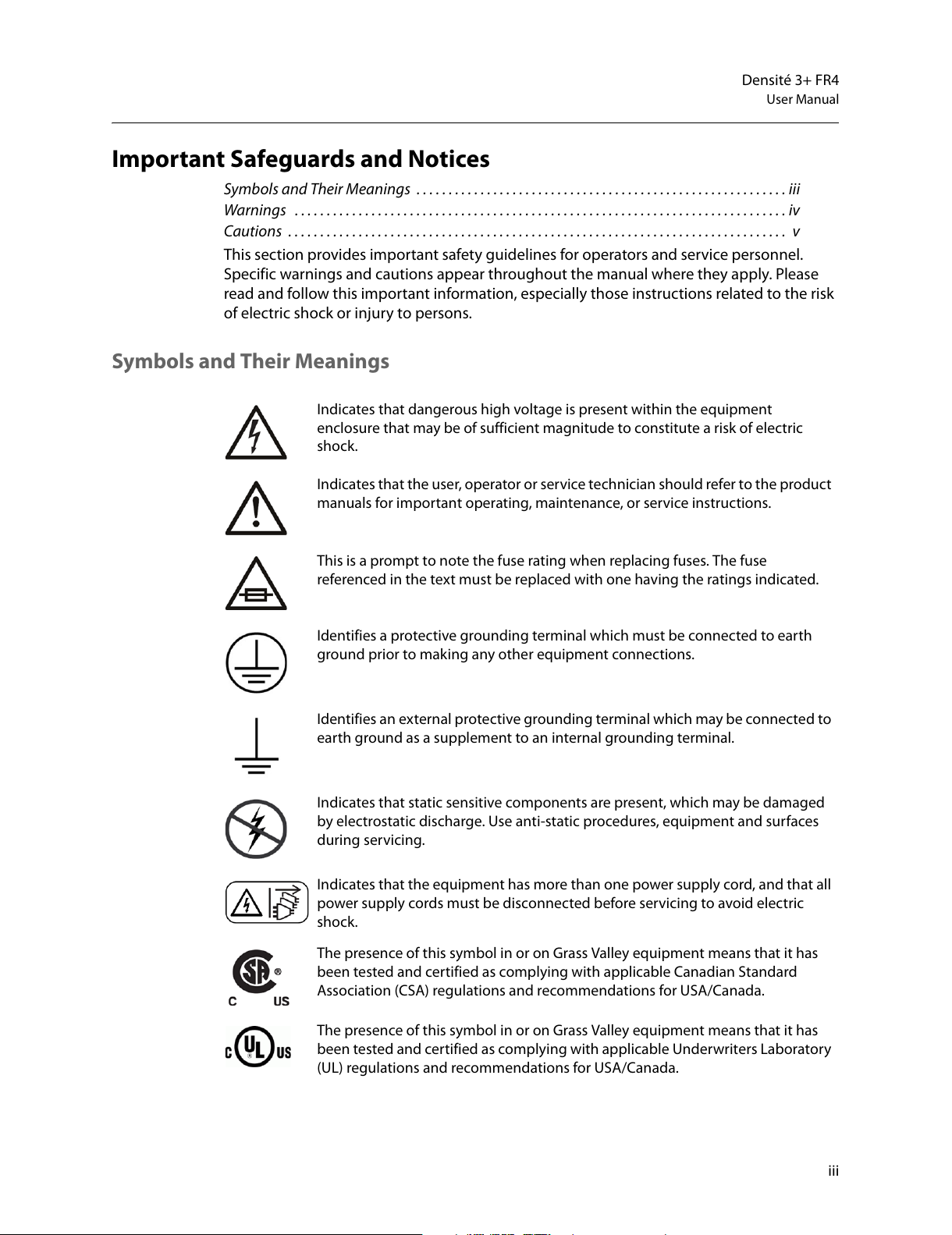
Symbols and Their Meanings
Indicates that dangerous high voltage is present within the equipment
enclosure that may be of sufficient magnitude to constitute a risk of electric
shock.
Indicates that the user, operator or service technician should refer to the product
manuals for important operating, maintenance, or service instructions.
This is a prompt to note the fuse rating when replacing fuses. The fuse
referenced in the text must be replaced with one having the ratings indicated.
Identifies a protective grounding terminal which must be connected to earth
ground prior to making any other equipment connections.
Identifies an external protective grounding terminal which may be connected to
earth ground as a supplement to an internal grounding terminal.
Indicates that static sensitive components are present, which may be damaged
by electrostatic discharge. Use anti-static procedures, equipment and surfaces
during servicing.
Indicates that the equipment has more than one power supply cord, and that all
power supply cords must be disconnected before servicing to avoid electric
shock.
The presence of this symbol in or on Grass Valley equipment means that it has
been tested and certified as complying with applicable Canadian Standard
Association (CSA) regulations and recommendations for USA/Canada.
The presence of this symbol in or on Grass Valley equipment means that it has
been tested and certified as complying with applicable Underwriters Laboratory
(UL) regulations and recommendations for USA/Canada.
All manuals and user guides at all-guides.com
Page 4
iv
Notices
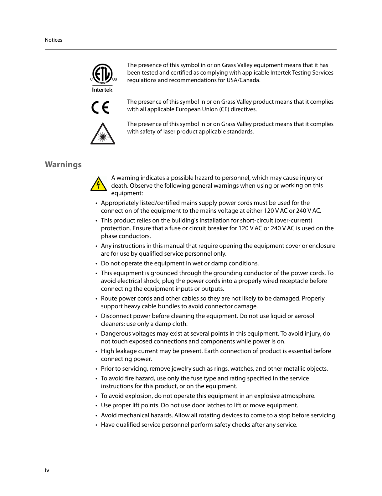
Warnings
A warning indicates a possible hazard to personnel, which may cause injury or
death. Observe the following general warnings when using or w
orking on this
equipment:
• Appropriately listed/certified mains sup
ply power cords must be used for the
connection of the equipment to the mains voltage at either 120 V AC or 240 V AC.
• This product relies on the building's installation for short-circuit (over-current)
pr
otection. Ensure that a fuse or circuit breaker for 120 V AC or 240 V AC is used on the
ph
ase conductors.
• Any instructions in this manual that requir
e opening the equipment cover or enclosure
are for use by qualified service personnel only.
• Do not operate the equipment in wet or damp conditions.
• This equipment is grounded through the grounding conductor of the power cords. To
a
void electrical shock, plug the power cords into a properly wired receptacle before
connecting the equipment inputs or outputs.
• Route power cords and other cables so they a
re not likely to be damaged. Properly
support heavy cable bundles to avoid connector damage.
• Disconnect power before cleaning the equipment. Do not use liquid or aerosol
cl
eaners; use only a damp cloth.
• Dangerous voltages may exist at several points in this equipment. To avoid injury, do
not touch exposed connec
tions and components while power is on.
• High leakage current may be present. Earth connection of product is essential before
c
onnecting power.
• Prior to servicing, remove jewelry such as r
ings, watches, and other metallic objects.
• To avoid fire hazard, use only the fuse type and rating specified in the service
instruc
tions for this product, or on the equipment.
• To avoid explosion, do not operate this equipment in an explosive atmosphere.
• Use proper lift points. Do not use door
latches to lift or move equipment.
• Avoid mechanical hazards. Allow all rotating devices to come to a stop before servicing.
• Have qualified service personnel perform saf
ety checks after any service.
The presence of this symbol in or on Grass Valley equipment means that it has
been tested and certified as complying with applicable Intertek Testing Services
regulations and recommendations for USA/Canada.
The presence of this symbol in or on Grass Valley product means that it complies
with all applicable European Union (CE) directives.
The presence of this symbol in or on Grass Valley product means that it complies
with safety of laser product applicable standards.
All manuals and user guides at all-guides.com
Page 5

v
Densité 3+ FR4
User Manual
Cautions
A caution indicates a possible hazard to equipment that could result in equipment
damage. Observe the following cautions when operating or working on this
equip
ment:
• This equipment is meant to be installed in a restricted access location.
• When installing this equipment, do not attach the power cord to building surfaces.
• Products that have no on/off switch, and use an external power supply must be
installed in pr
oximity to a main power outlet that is easily accessible.
• Use the correct voltage setting. If this product lacks auto-ranging power supplies,
b
efore applying power ensure that each power supply is set to match the power
source.
• Provide proper ventilation. To prevent product overheating, provide equipment
v
entilation in accordance with the installation instructions.
• Do not operate with suspected equipment failur
e. If you suspect product damage or
equipment failure, have the equipment inspected by qualified service personnel.
• To reduce the risk of electric shock, do not per
form any servicing other than that
contained in the operating instructions unless you are qualified to do so. Refer all
servicing to qualified service personnel. Servicing should be done in a static-free
environment.
• This unit may have more than one power supply cord. Disconnect all power supply
c
ords before servicing to avoid electric shock.
• Follow static precautions at all times when handling this equipment.
Electrostatic Discharge (ESD) Protection
Electrostatic discharge occurs when electronic components are improperly
handled and can result in intermittent failur
e or complete damage adversely
affecting an electrical circuit. When you remove and replace any card from a frame
always follow ESD-prevention procedures:
• Ensure that the frame is electrically connected
to earth ground through the power cord
or any other means if available.
• Wear an ESD wrist strap ensuring that it makes good skin contact. Connect the
gr
ounding clip to an unpainted surface of the chassis frame to safely ground unwanted
ESD voltages. If no wrist strap is available, ground yourself by touching the unpainted
metal part of the chassis.
• For safety, periodically check the resistance value of the antistatic strap, which should
be
between 1 and 10 megohms.
• When temporarily storing a car
d make sure it is placed in an ESD bag.
• Cards in an earth grounded metal frame or casing do not require any special ESD
pr
otection.
Mesures de sécurité et avis importants
Signification des symboles utilisés . . . . . . . . . . . . . . . . . . . . . . . . . . . . . . . . . . . . . . . . . . . . . . . . . . . . . vi
Avertissements . . . . . . . . . . . . . . . . . . . . . . . . . . . . . . . . . . . . . . . . . . . . . . . . . . . . . . . . .
. . . . . . . . . . . . . . vii
All manuals and user guides at all-guides.com
Page 6
vi
Notices
Mises en gardeLes mises en garde signalent des conditions ou des pratiques susceptibles
d’endommager l’équipement. Veuillez vous famili
ariser avec les mises en garde ci-dessous :
viiiLa présente section fournit des consignes de sécurité importantes pour les opérateurs et
le personnel de service. Des avertissements ou mises en gar
de spécifiques figurent dans le
manuel, dans les sections où ils s’appliquent. Prenez le temps de bien lire les consignes et
assurez-vous de les respecter, en particulier celles qui sont destinées à prévenir les
décharges électriques ou les blessures.
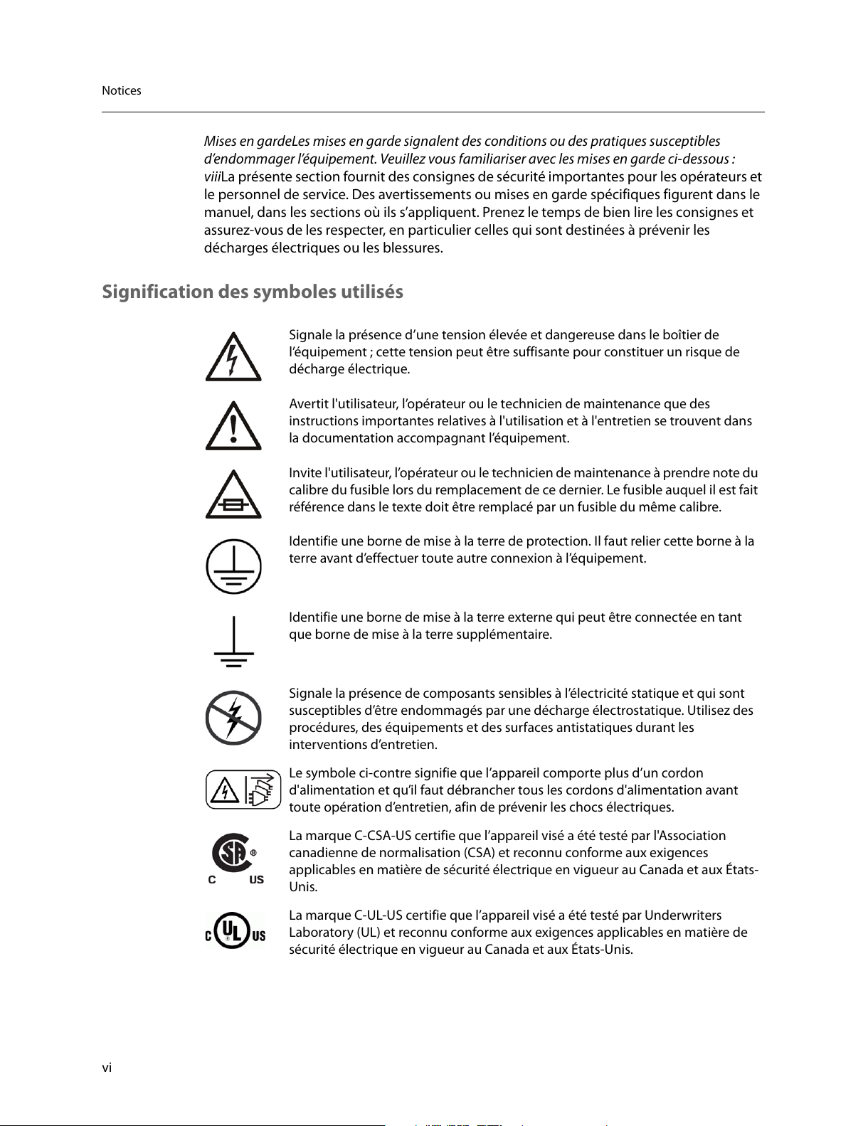
Signification des symboles utilisés
Signale la présence d’une tension élevée et dangereuse dans le boîtier de
l’équipement ; cette tension peut être suffisante pour constituer un risque de
déchar
ge électrique.
Avertit l'utilisateur, l’opérateur ou le technicien de maintenance que des
instructions importantes relatives à l'utilisation et à l'entretien se trouvent dans
la documentation accompagnant l’équipement.
Invite l'utilisateur, l’opérateur ou le technicien de maintenance à prendre note du
calibre du fusible lors du remplacement de ce dernier. Le fusible auquel il est fait
référence dans le texte doit être remplacé par un fusible du même calibre.
Identifie une borne de mise à la terre de protection. Il faut relier cette borne à la
terre avant d’effectuer toute autre connexion à l’équipement.
Identifie une borne de mise à la terre externe qui peut être connectée en tant
que borne de mise à la terre supplémentaire.
Signale la présence de composants sensibles à l’électricité statique et qui sont
susceptibles d’être endommagés par une décharge électrostatique. Utilisez des
procédures, des équipements et des surfaces antistatiques durant les
interventions d’entretien.
Le symbole ci-contre signifie que l’appareil comporte plus d’un cordon
d'alimentation et qu’il faut débrancher tous les cordons d'alimentation avant
toute opération d’entretien, afin de prévenir les chocs électriques.
La marque C-CSA-US certifie que l’appareil visé a été testé par l'Association
canadienne de normalisation (CSA) et reconnu conforme aux exigences
applicables en matière de sécurité électrique en vigueur au Canada et aux États-
Unis.
La marque C-UL-US certifie que l’appareil visé a été testé par Underwriters
Laboratory (UL) et reconnu conforme aux exigences applicables en matière de
sécurité électrique en vigueur au Canada et aux États-Unis.
All manuals and user guides at all-guides.com
Page 7
vii
Densité 3+ FR4
User Manual
Avertissements
Les avertissements signalent des conditions ou des pratiques susceptibles
d’occasionner des blessures graves, voire fatales
. Veuillez vous familiariser avec les
avertissements d’ordre général ci-dessous :
• Un cordon d’alimentation dûment homologué doit être utilisé pour connecter
l’
appareil à une tension de secteur de 120 V CA ou 240 V CA.
• La protection de ce produit contre les cour
ts-circuits (surintensités) dépend de
l’installation électrique du bâtiment. Assurez-vous qu'un fusible ou un disjoncteur pour
120 V CA ou 240 V CA est utilisé sur les conducteurs de phase.
• Dans le présent manuel, toutes les instructions qui néc
essitent d’ouvrir le couvercle de
l’équipement sont destinées exclusivement au personnel technique qualifié.
• N’utilisez pas cet appareil dan
s un environnement humide.
• Cet équipement est mis à la terre par le conducteur de mise à la terre des cordons
d
’alimentation. Pour éviter les chocs électriques, branchez les cordons d’alimentation
sur une prise correctement câblée avant de brancher les entrées et sorties de
l’équipement.
• Acheminez les cordons d’alimentation et autres câbles de faç
on à ce qu’ils ne risquent
pas d’être endommagés. Supportez correctement les enroulements de câbles afin de
ne pas endommager les connecteurs.
• Coupez l’alimentation avant de nettoyer l’équipemen
t. Ne pas utiliser de nettoyants
liquides ou en aérosol. Utilisez uniquement un chiffon humide.
• Des tensions dangereuses peuvent exister en plusie
urs points dans cet équipement.
Pour éviter toute blessure, ne touchez pas aux connexions ou aux composants exposés
lorsque l’appareil est sous tension.
• Avant de procéder à toute opération d’entretien ou de dépannage, enlevez tous vos
b
ijoux (notamment vos bagues, votre montre et autres objets métalliques).
• Pour éviter tout risque d’incendie, utilisez uniquement les fusibl
es du type et du calibre
indiqués sur l’équipement ou dans la documentation qui l’accompagne.
• Ne pas utiliser cet appareil dans une atmosphèr
e explosive.
• Présence possible de courants de fuite. Un raccordement à la masse est indispensable
avant la mise sous tension.
La marque ETL Listed d’Intertek pour le marché Nord-Américain certifie que
l’appareil visé a été testé par Intertek et reconnu conforme aux exigences
applicables en matière de sécurité électrique en vigueur au Canada et aux États-
Unis.
Le marquage CE indique que l’appareil visé est conforme aux exigences
essentielles des directives applicables de l’Union européenne en matière de
sécurité électrique, de compatibilité électromagnétique et de conformité
environnementale.
Le symbole ci-contre sur un appareil Grass Valley ou à l’intérieur de l’appareil
indique qu’il est conforme aux normes applicables en matière de sécurité laser.
All manuals and user guides at all-guides.com
Page 8
viii
Notices
• Après tout travail d’entretien ou de réparation, faites effectuer des contrôles de sécurité
par le personnel technique qualifié.
Mises en gardeLes mises en garde signalent des conditions ou des pratiques
susceptibles d’endommager l’équipement. Veuillez v
ous familiariser avec les mises
en garde ci-dessous :
• L’appareil est conçu pour être installé dans un endroit à accès restreint.
• Au moment d’installer l’équipement, ne fix
ez pas les cordons d’alimentation aux
surfaces intérieures de l’édifice.
• Les produits qui n'ont pas d’interrupteur mar
che-arrêt et qui disposent d’une source
d’alimentation externe doivent être installés à proximité d'une prise de courant facile
d’accès.
• Si l’équipement n’est pas pourvu d’un modules d
’alimentation auto-adaptables, vérifiez
la configuration de chacun des modules d'alimentation avant de les mettre sous
tension.
• Assurez une ventilation adéquate. Pour éviter toute su
rchauffe du produit, assurez une
ventilation de l’équipement conformément aux instructions d’installation.
• N’utilisez pas l’équipement si vous suspectez un dy
sfonctionnement du produit. Faites-
le inspecter par un technicien qualifié.
• Pour réduire le risque de choc électrique, n
'effectuez pas de réparations autres que
celles qui sont décrites dans le présent manuel, sauf si vous êtes qualifié pour le faire.
Confiez les réparations à un technicien qualifié. La maintenance doit se réaliser dans un
milieu libre d’électricité statique.
• L’appareil peut comporter plus d’un cordon d'alimenta
tion. Afin de prévenir les chocs
électriques, débrancher tous les cordons d'alimentation avant toute opération
d’entretien.
• Veillez à toujours prendre les mesures de protection antistatique appropriées quand
v
ous manipulez l’équipement.
Protection contre les décharges électrostatiques (DES)
Une décharge électrostatique peut se produire lorsque des composants
électroniques ne sont pas manipulés de manière adéquate, ce qui peut entraîner
des défaillanc
es intermittentes ou endommager irrémédiablement un circuit
électrique. Au moment de remplacer une carte dans un châssis, prenez toujours les
mesures de protection antistatique appropriées :
• Assurez-vous que le châssis est relié électriquement à la terre par le cordon
d'
alimentation ou tout autre moyen disponible.
• Portez un bracelet antistatique et assur
ez-vous qu'il est bien en contact avec la peau.
Connectez la pince de masse à une surface non peinte du châssis pour détourner à la
terre toute tension électrostatique indésirable. En l’absence de bracelet antistatique,
déchargez l’électricité statique de votre corps en touchant une surface métallique non
peinte du châssis.
• Pour plus de sécurité, vérifiez périodiquement la valeur de résistance du bracelet
antistatique. Elle doit se situer entre 1 et 10 mégohms.
• Si vous devez mettre une carte de côté, assur
ez-vous de la ranger dans un sac
protecteur antistatique.
All manuals and user guides at all-guides.com
Page 9

ix
Densité 3+ FR4
User Manual
• Les cartes qui sont reliées à un châssis ou boîtier métallique mis à la terre ne
nécessitent pas de protection antistatique spéciale.
Recycling
Visit www.grassvalley.com for recycling information.
Certification and Compliance
Safety Compliance
This equipment complies with the requirements of CSA/UL/IEC/EN 60950-1, 2nd
Ed. + AM1, Safety of information technology equipment.
The power cords supplied with this equipment meet the appropriate national
st
andards for the country of destination.
Environmental Compliance
GVN FR4
部件名称
Part name
有毒有害物质或元素 (Toxic or hazardous substances and elements)
铅
(Pb)
汞
(Hg)
镉
(Cd)
六价铬
(Cr6)
多溴联苯
(PBB)
多溴二苯
(PBDE)
电缆及电缆组件 Cables and cable assemblies
X O O O O O
电路模块 Circuit modules
X O X O O O
显示装置 Display Assemblies
X O O O O O
组装风扇 Fan Assemblies
X O O O O O
金属零件 Metal parts
X O O O O O
O
: 表示该有毒有害物质在该部件所有均质材料中的含量均在 GB/T 26572-2011 规定的
限量要求以下。
O: Indicates that this toxic or hazardous substance contained in all of the homogeneous
materials for this part is below the limit requirement in GB/T 26572-2011.
X: 表示该有毒有害物质至少在该部件的某一均质材料中的含量超出 GB/T 26572-2011
规定的限量要求。
X: Indicates that this toxic or hazardous substance contained in at least one of the
homogeneous materials for this part is above the limit requirement in GB/T 26572-2011.
技术条款解释:此声明所依据之数据由 Grass Valley 环境管理部门向我们的部件供
应商获取。Grass Valley 公司相信此信息的正确性,但由于数据来源于公司外部,我
们无法保证它的完整和准确。所有这些特性可能在未获通知的情况下更改。
Technical explanations: This statement is based on the inf
ormation provided by our
suppliers of components and collected through our Grass Valley’s environmental
management system. Grass Valley believes this environmental information to be correct
but cannot guarantee its completeness or accuracy as it is based on data received from
sources outside our company. All specifications are subject to change without notice.
All manuals and user guides at all-guides.com
Page 10

x
Notices
Electromagnetic Compatibility
This equipment has been tested for verification of compliance with FCC Part 15,
Subpart B requirements for class A digital devices.
Note: This equipment has been tested and found to comply with the limits
for a Class A digital device, pursuant to Part 15 of the FCC rules. These limits
are designed to provide reasonable protection against harmful interference
when the equipment is operated in a commercial environment. This
equipment generates, uses, and can radiate radio frequency energy, and, if
not installed and used in accordance with the instruction manual, may cause
harmful interference to radio communications. Operation of this equipment
in a residential area is likely to cause harmful interference in which case the
user will be required to correct the interference at his own expense.
This equipment has been tested and found to comply with the requirements of
the EMC directive 2004/108/EC:
• EN 55022 Class A Radiated and conducted emissions
• EN 61000-3-2 Limits for harmonic current emissions
• EN 61000-3-3 Limitation of voltage fluctuations and flicker
• EN 61000-4-2 Electrostatic discharge immunity
• EN 61000-4-3 Radiated, radio-frequency, electromagnetic field immunity
• EN 61000-4-4 Electrical fast transient immunity
• EN 61000-4-5 Surge transient immunity
• EN 61000-4-6 Conducted disturbances immunity
• EN 61000-4-8 Power frequency magnetic field immunity
• EN 61000-4-11 Voltage dips, short interruptions and voltage variations
immunit
y
All manuals and user guides at all-guides.com
Page 11
xi
Table of Contents
1 Introduction . . . . . . . . . . . . . . . . . . . . . . . . . . . . . . . . . . . . . . . . . . . 1
The Densité 3+ FR4 Frame . . . . . . . . . . . . . . . . . . . . . . . . . . . . . . . . . . . . . . . . . . . . . . . . . . 1
Overview - Frame . . . . . . . . . . . . . . . . . . . . . . . . . . . . . . . . . . . . . . . . . . . . . . . . . . . . . . . . . .1
Overview - Controller . . . . . . . . . . . . . . . . . . . . . . . . . . . . . . . . . . . . . . . . . . . . . . . . . . . . . .2
Description . . . . . . . . . . . . . . . . . . . . . . . . . . . . . . . . . . . . . . . . . . . . . . . . . . . . . . . . . . . . . . . .3
Mechanical Layout . . . . . . . . . . . . . . . . . . . . . . . . . . . . . . . . . . . . . . . . . . . . . . . . . . . . . . . . .3
Controller Rear Panel . . . . . . . . . . . . . . . . . . . . . . . . . . . . . . . . . . . . . . . . . . . . . . . . . . . . . . . 5
2 Installation. . . . . . . . . . . . . . . . . . . . . . . . . . . . . . . . . . . . . . . . . . . . . 7
Installation . . . . . . . . . . . . . . . . . . . . . . . . . . . . . . . . . . . . . . . . . . . . . . . . . . . . . . . . . . . . . . . . . 7
Unpacking . . . . . . . . . . . . . . . . . . . . . . . . . . . . . . . . . . . . . . . . . . . . . . . . . . . . . . . . . . . . . . . . .7
Opening the Front Door . . . . . . . . . . . . . . . . . . . . . . . . . . . . . . . . . . . . . . . . . . . . . . . . . . . . . . . 7
Mounting . . . . . . . . . . . . . . . . . . . . . . . . . . . . . . . . . . . . . . . . . . . . . . . . . . . . . . . . . . . . . . . . . . . . . 8
Installing Cards in the Densité 3+ FR4 Frame . . . . . . . . . . . . . . . . . . . . . . . . . . . . . . . .8
Installing the Power Cord Retaining Clips. . . . . . . . . . . . . . . . . . . . . . . . . . . . . . . . . . . . . .11
Ventilation . . . . . . . . . . . . . . . . . . . . . . . . . . . . . . . . . . . . . . . . . . . . . . . . . . . . . . . . . . . . . . . . . . .11
3 Configuration . . . . . . . . . . . . . . . . . . . . . . . . . . . . . . . . . . . . . . . . . 13
Control Interfaces . . . . . . . . . . . . . . . . . . . . . . . . . . . . . . . . . . . . . . . . . . . . . . . . . . . . . . . . 13
Using the Ethernet interface . . . . . . . . . . . . . . . . . . . . . . . . . . . . . . . . . . . . . . . . . . . . . . . . . .13
Using the local control interface . . . . . . . . . . . . . . . . . . . . . . . . . . . . . . . . . . . . . . . . . . . . . .15
Using the Controller’s web page . . . . . . . . . . . . . . . . . . . . . . . . . . . . . . . . . . . . . . . . . . . . . .16
Configuring the CPU-ETH3 Controller . . . . . . . . . . . . . . . . . . . . . . . . . . . . . . . . . . . . . 17
Identification . . . . . . . . . . . . . . . . . . . . . . . . . . . . . . . . . . . . . . . . . . . . . . . . . . . . . . . . . . . . . . . .18
Status Monitoring . . . . . . . . . . . . . . . . . . . . . . . . . . . . . . . . . . . . . . . . . . . . . . . . . . . . . . . . . . .19
Network . . . . . . . . . . . . . . . . . . . . . . . . . . . . . . . . . . . . . . . . . . . . . . . . . . . . . . . . . . . . . . . . . . . . .22
Link Redundancy . . . . . . . . . . . . . . . . . . . . . . . . . . . . . . . . . . . . . . . . . . . . . . . . . . . . . . . . . . . .22
Data Restoration . . . . . . . . . . . . . . . . . . . . . . . . . . . . . . . . . . . . . . . . . . . . . . . . . . . . . . . . . . . . .23
Factory Alignment . . . . . . . . . . . . . . . . . . . . . . . . . . . . . . . . . . . . . . . . . . . . . . . . . . . . . . . . . . .25
Time Management. . . . . . . . . . . . . . . . . . . . . . . . . . . . . . . . . . . . . . . . . . . . . . . . . . . . . . . . . . .26
Alarms . . . . . . . . . . . . . . . . . . . . . . . . . . . . . . . . . . . . . . . . . . . . . . . . . . . . . . . . . . . . . . . . . . . . . . .27
Local Control Panel Menu - CPU-ETH3 . . . . . . . . . . . . . . . . . . . . . . . . . . . . . . . . . . . . . . . .31
Upgrading the CPU-ETH3 Controller . . . . . . . . . . . . . . . . . . . . . . . . . . . . . . . . . . . . . . 32
Configuring the Frame Reference . . . . . . . . . . . . . . . . . . . . . . . . . . . . . . . . . . . . . . . . . 33
Reference Source . . . . . . . . . . . . . . . . . . . . . . . . . . . . . . . . . . . . . . . . . . . . . . . . . . . . . . . . . . . .34
URS Generation . . . . . . . . . . . . . . . . . . . . . . . . . . . . . . . . . . . . . . . . . . . . . . . . . . . . . . . . . . . . . .34
Timecode . . . . . . . . . . . . . . . . . . . . . . . . . . . . . . . . . . . . . . . . . . . . . . . . . . . . . . . . . . . . . . . . . . . .35
Alarms . . . . . . . . . . . . . . . . . . . . . . . . . . . . . . . . . . . . . . . . . . . . . . . . . . . . . . . . . . . . . . . . . . . . . . .36
Information . . . . . . . . . . . . . . . . . . . . . . . . . . . . . . . . . . . . . . . . . . . . . . . . . . . . . . . . . . . . . . . . . .37
All manuals and user guides at all-guides.com
Page 12
xii
Table of Contents
Factory Settings . . . . . . . . . . . . . . . . . . . . . . . . . . . . . . . . . . . . . . . . . . . . . . . . . . . . . . . . . . . . .39
Upgrading the Frame Reference . . . . . . . . . . . . . . . . . . . . . . . . . . . . . . . . . . . . . . . . . . 40
4 Service and Maintenance . . . . . . . . . . . . . . . . . . . . . . . . . . . . . . 41
Changing the Power Supply . . . . . . . . . . . . . . . . . . . . . . . . . . . . . . . . . . . . . . . . . . . . . . 41
Replacing the Controller . . . . . . . . . . . . . . . . . . . . . . . . . . . . . . . . . . . . . . . . . . . . . . . . . . 42
Replacing the Frame Ventilation Fans . . . . . . . . . . . . . . . . . . . . . . . . . . . . . . . . . . . . . 43
Cleaning and replacing the front-door air filter . . . . . . . . . . . . . . . . . . . . . . . . . . . . 44
Contact Us . . . . . . . . . . . . . . . . . . . . . . . . . . . . . . . . . . . . . . . . . . . . . . . 47
Grass Valley Technical Support . . . . . . . . . . . . . . . . . . . . . . . . . . . . . . . . . . . . . . . . . . . 47
Corporate Head Office . . . . . . . . . . . . . . . . . . . . . . . . . . . . . . . . . . . . . . . . . . . . . . . . . . . 47
All manuals and user guides at all-guides.com
Page 13
1
Introduction
Summary
Overview - Frame . . . . . . . . . . . . . . . . . . . . . . . . . . . . . . . . . . . . . . . . . . . . . . . . . . . . . . . . . . . . . . . . . . . . . page 1
Overview - Controller
. . . . . . . . . . . . . . . . . . . . . . . . . . . . . . . . . . . . . . . . . . . . . . . . . . . . . . . . . . . . . . . . . page 2
Mechanical Layout
. . . . . . . . . . . . . . . . . . . . . . . . . . . . . . . . . . . . . . . . . . . . . . . . . . . . . . . . . . . . . . . . . . . page 3
Controller Rear Panel
. . . . . . . . . . . . . . . . . . . . . . . . . . . . . . . . . . . . . . . . . . . . . . . . . . . . . . . . . . . . . . . . . page 5
Specifications
. . . . . . . . . . . . . . . . . . . . . . . . . . . . . . . . . . . . . . . . . . . . . . . . . . . . . . . . . . . . . . . . . . . . . . . . page 6
The Densité 3+ FR4 Frame
Overview - Frame
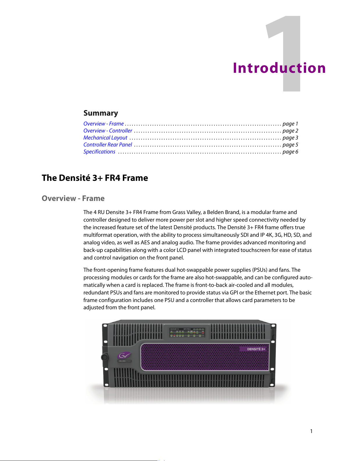
The 4 RU Densite 3+ FR4 Frame from Grass Valley, a Belden Brand, is a modular frame and
controller designed to deliver more power per slot and higher speed connectivity needed by
the increased feature set of the latest Densité products. The Densité 3+ FR4 frame offers true
multiformat operation, with the ability to process simultaneously SDI and IP 4K, 3G, HD, SD, and
analog video, as well as AES and analog audio. The frame provides advanced monitoring and
back-up capabilities along with a color LCD panel with integrated touchscreen for ease of status
and control navigation on the front panel.
The front-opening frame features dual hot-swappable power supplies (PSUs) and fans. The
pr
ocessing modules or cards for the frame are also hot-swappable, and can be configured auto-
matically when a card is replaced. The frame is fr
ont-to-back air-cooled and all modules,
redundant PSUs and fans are monitored to provide status via GPI or the Ethernet port. The basic
frame configuration includes one PSU and a controller that allows card parameters to be
adjusted from the front panel.
All manuals and user guides at all-guides.com
Page 14
2
Introduction
Key Product Capabilities
• Fully backwards compatible with Densité 2 and Densité 3 cards.
• 24 slots with a power budget of 25 watts per slots.
• Optional frame reference on controller card.
• Fully modular I/O for the frame controller for “future readiness” of the controller I/O.
• Dual GigE port for system wide redundancy.
• Full touchscreen color LCD panel for module status and control.
Standard Densité capabilities
• Multiple video and audio formats can be fitted in a single frame.
• Densité 3 RU and Densité 2 RU modules can co-exist in the same frame.
• Easy configuration by front panel or remotely via the Ethernet frame controller.
• Choice of control panels, including the PC-based iControl Solo GUI.
• Hot-swappable power supply, with optional redundant power supply.
• Supports full range of Densité Series modules.
• Frame can be stacked without additional cooling spaces.
• Optional redundant Ethernet connection.
Available Options
• Second power supply for redundant power security
• Full link redundancy using Channel Bonding on the CPU-ETH3
• Frame reference integrated with controller
Cards (maximum 24 per frame)
The Densité 3+ FR4 housing frame supports all current Densité 3 series cards directly. Many
Densité 2 series cards can also be installed with the use of an adapter that fits on the card, plus
an additional adapter to extend the rear panel if a dedicated 3RU rear is not available..
Overview - Controller
The CPU-ETH3 controller installed in the Densité 3+ FR4 frame supports all on-frame communi-
cation between cards, and incorporates a touch-screen panel for local control and adjustment of
the frame and installed cards. The CPU-ETH3 controller serves as the communications port for
control and alarm information entering and leaving the frame. The CPU-ETH3 controller features
two Ethernet ports for system-wide monitoring and control of the frame, using Miranda’s
control solutions. This controller card is compatible with the TCP/IP protocol and can support
polling or report on error modes (unsolicited messaging).
All manuals and user guides at all-guides.com
Page 15
3
Densité 3+ FR4
User Manual
Features
• Dual Ethernet RJ-45 ports (100Base-T and Gigabit Ethernet) - the two ports can be config-
ured independently for full network redundancy
• Provides ultra-robust Ethernet connectivity for LAN/WAN
• Accelerated data throughput: allows video thumbnail and audio level meter and line scope
streaming from all installed modular cards
• Linux-based operating system for robust, mission-critical operations
• Removable SD memory card for portable and quickly-recoverable device and frame configu-
ration
• User-configurable GPI alarm port
• Features front display panel and push-buttons for local configuration of cards and frame
• Can be remotely configured via iControl
• Provides card and frame health monitoring and status reporting
• Provides extensive frame monitoring:
- Ethernet port monitoring, with communication settings and overall bit rate
- detailed bitrate and communication thoughput from individual cards
- self-monitoring with CPU load, memory usage
- Power Supply and GPI status reporting
• Individual Card parameter storage for easy card swapping
• optional integrated frame refrence module
Description
Mechanical Layout
The Densité 3+ FR4 is a 4 RU frame.
• The upper section contains the power supplies and the controller card.
• The lower portion consists of 24 slots that accept Densité-3 cards.
All manuals and user guides at all-guides.com
Page 16
4
Introduction
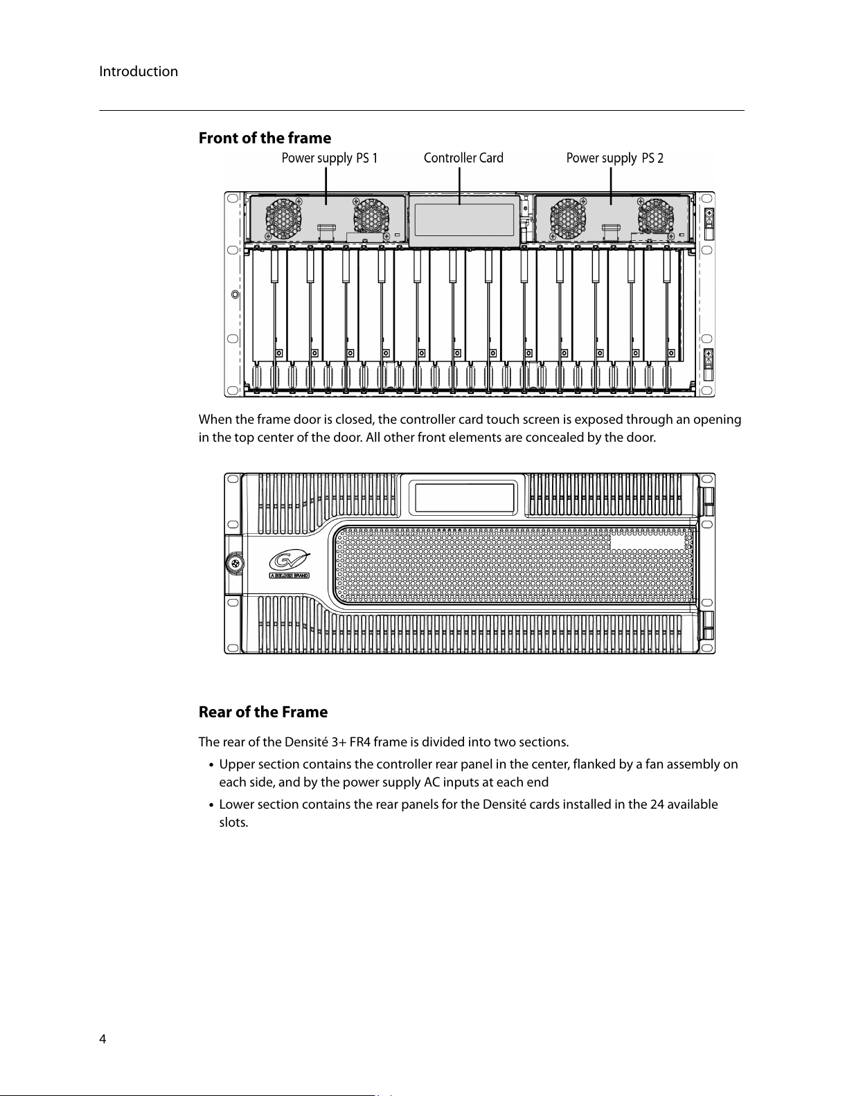
Front of the frame
When the frame door is closed, the controller card touch screen is exposed through an opening
in the top center of the door. All other front elements are concealed by the door.
Rear of the Frame
The rear of the Densité 3+ FR4 frame is divided into two sections.
• Upper section contains the controller rear panel in the center, flanked by a fan assembly on
each side, and by the power supply AC inputs at each end
• Lower section contains the rear panels for the Densité cards installed in the 24 available
slots.
All manuals and user guides at all-guides.com
Page 17
5
Densité 3+ FR4
User Manual
Controller Rear Panel
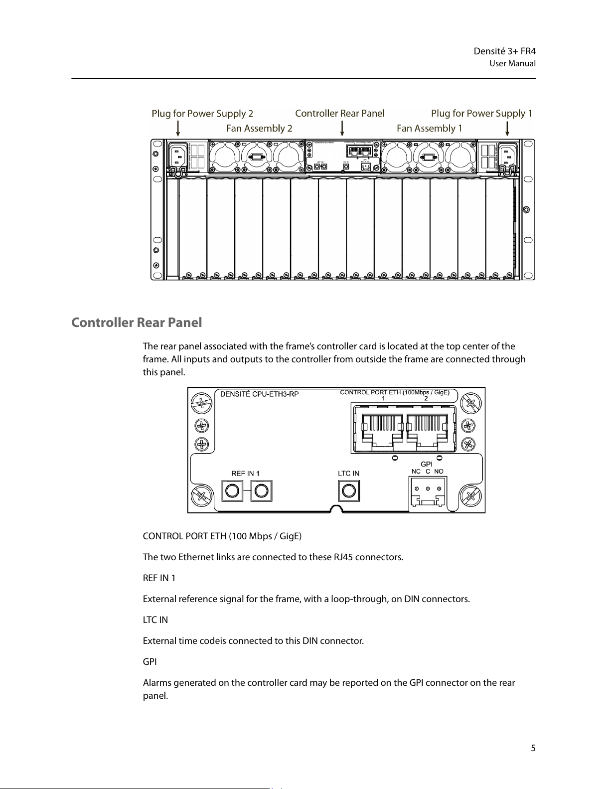
The rear panel associated with the frame’s controller card is located at the top center of the
frame. All inputs and outputs to the controller from outside the frame are connected through
this panel.
CONTROL PORT ETH (100 Mbps / GigE)
The two Ethernet links are connected to these RJ45 connectors.
REF IN 1
External reference signal for the frame, with a loop-through, on DIN connectors.
LTC IN
External time codeis connected to this DIN connector.
GPI
Alarms generated on the controller card may be
reported on the GPI connector on the rear
panel.
All manuals and user guides at all-guides.com
Page 18
6
Introduction
Specifications
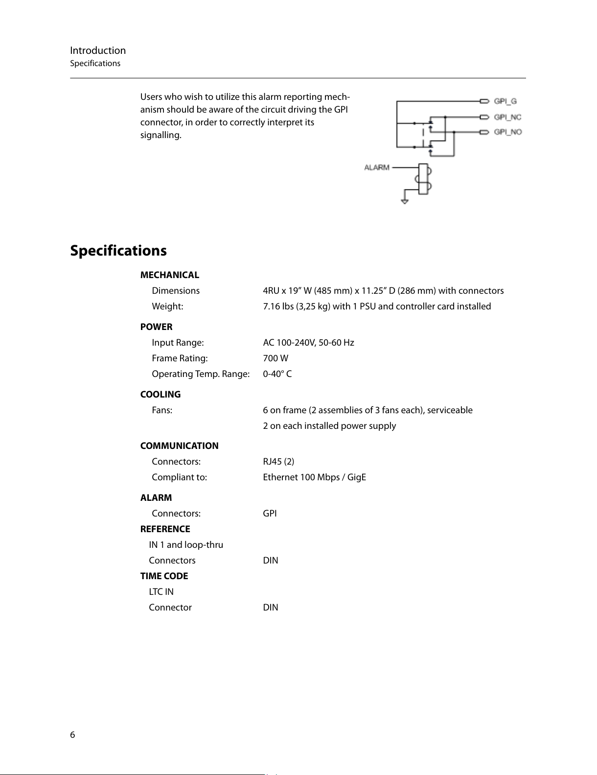
Users who wish to utilize this alarm reporting mech-
anism should be aware of the circuit driving the GPI
co
nnector, in order to correctly interpret its
signalling.
Specifications
MECHANICAL
Dimensions 4RU x 19” W (485 mm) x 11.25” D (286 mm) with connectors
W
eight: 7.16 lbs (3,25 kg) with 1 PSU and controller card installed
POWER
Input Range: AC 100-240V, 50-60 Hz
Fr
ame Rating: 700 W
Operating Temp. Range: 0-40° C
COOLING
Fans: 6 on frame (2 assemblies of 3 fans each), serviceable
2
on each installed power supply
COMMUNICATION
Connectors: RJ45 (2)
C
ompliant to: Ethernet 100 Mbps / GigE
ALARM
Connectors: GPI
REF
ERENCE
IN 1 and loop-thru
Connectors DIN
TIME CODE
LTC IN
Connector DIN
All manuals and user guides at all-guides.com
Page 19

7
Installation
Summary
Unpacking . . . . . . . . . . . . . . . . . . . . . . . . . . . . . . . . . . . . . . . . . . . . . . . . . . . . . . . . . . . . . . . . . . . . . . . . . . . . 7
Opening the Front Door . . . . . . . . . . . . . . . . . . . . . . . . . . . . . . . . . . . . . . . . . . . . . . . . . . . . . . . . . . . . . . . 7
Mounting . . . . . . . . . . . . . . . . . . . . . . . . . . . . . . . . . . . . . . . . . . . . . . . . . . . . . . . . . . . . . . . . . . . . . . . . . . . . . 8
Installing Cards in the Densité 3+ FR4 Frame . . . . . . . . . . . . . . . . . . . . . . . . . . . . . . . . . . . . . . . . . . . 8
Using Densité 2 cards in the Densité 3+ FR4 Frame . . . . . . . . . . . . . . . . . . . . . . . . . . . . . . . . . . . . . 9
Installing the Power Cord Retaining Clips . . . . . . . . . . . . . . . . . . . . . . . . . . . . . . . . . . . . . . . . . . . . . 11
Ventilation . . . . . . . . . . . . . . . . . . . . . . . . . . . . . . . . . . . . . . . . . . . . . . . . . . . . . . . . . . . . . . . . . . . . . . . . . . . 11
Installation
Unpacking
Make sure the following items have been shipped with your Densité 3+ FR4 frame:
• Densité 3+ FR4 frame, including 1 Power Supply unit (AC in) with power cord
• Frame controller (Densité 3+ CPU-ETH3)
• Power cord retaining clips (2)
• A second power supply and AC cord (optional)
• Densité-series cards (per order) with associated rear panels
Opening the Front Door
The front door of the Densité 3+ FR4 frame is hinged on the right-hand side, and latched by a
captive thumbscrew on the left-hand side. There are no electrical connections to the door.
To open the door
• Turn the thumbscrew clockwise until it releases, and pull the door open.
• The door can be removed completely after it is open by sliding it vertically off the hinge pins
on the right-hand side.
To install and close the door
• Slide the door down onto the hinge pins on the right-hand side
• Push the door into the closed position and turn the thumbscrew on the left-hand side coun-
terclockwise to latch the door in the closed position.
All manuals and user guides at all-guides.com
Page 20

8
Installation
Mounting
Mounting
The Densité 3+ FR4 housing frame occupies 4RU in a standard 19” rack.
To mount the frame
• Remove the front door to expose the rack mounting flanges at the ends of the chassis.
• Install the frame in the rack using 8 standard rack-mounting screws (not supplied) through
the eight holes in the mounting flanges.
Installing Cards in the Densité 3+ FR4 Frame
All Densité-series cards can be installed with the frame power on. Each card has a connector
which plugs into the frame’s backplane for distribution of power and connection to the
controller card, and a second connector that plugs into the associated rear panel for inputs and
outputs.
IMPORTANT - the rear panel must be installed bef
ore the card is inserted into the frame.
Note: If you need to install a Densité 2 series card in this frame
, which has Densité 3 slots, please
see Using Densité 2 cards in the Densité 3+ FR4 Frame, on page 9
To install the rear connector panel
1 If a card is installed in the slot whose rear panel is being changed, remove it as described
below.
2 Remove the existing panel (either blank or belonging to an existing card that is being
changed) by releasing the captive screw(s) on the bottom
3 Position the new panel and secure it in place with the captive screw(s) on the bottom.
All manuals and user guides at all-guides.com
Page 21

9
Densité 3+ FR4
User Manual
Card Installation and removal
1 Open the front door of the frame
2 To install a card into an empty slot, slide the card into the slot with the swivel handle to the
top, and push gently on the handle to seat the connectors. If the card requires a double-
width rear panel or larger to accommodate a large number of connectors, it should be
inserted into the right-hand slot. Inserting the card into the wrong slot will not damage the
card, and will be flagged by the on-card status LED flashing red to indicate that there is no
connection to the rear panel.
N.B. the rear panel must be installed before the card.
3 To remove a card from a slot, tilt the swivel handle on the front of the card to lever the con-
ne
ctors apart, then use the handle to pull the card straight out of the slot.
4 Close the front door of the frame
Note:
Detailed information about the rear panel connections is included in the user manual for the
card.
Using Densité 2 cards in the Densité 3+ FR4 Frame
The Densité 3+ FR4 frame supports Miranda Densité 2 series cards. Should you need to install a
Densité 2 card in your Densité 3+ FR4 frame, you will need two adapters – one for the card, and
one for the rear panel. These adapters extend the height of the Densité 2 devices so that they
will fit into the slots of the Densité 3+ FR4 frame. Note that some Densité 2 cards are available
with a 3 RU rear panel, and sold with the card adapter already attached.
All manuals and user guides at all-guides.com
Page 22

10
Installation
Mounting
Card adapters:
There are 3 different types of adapters that
can be used, depending on the Densité 2
ca
rd geometry:
o DENSITE 3-EXT-A
o
DENSITE 3-EXT-B
o DENSITE 3-EXT-C
Install these on the Densité 2
card as
follows:
1 Fit the top edge of the card into the
ho
lding slot along the bottom edge of
the adapter.
2 Align the holes in the top of the card with the holes on the adapter, and secure them
together with the two provided screws and lock washers, as shown in the figure.
Rear Adapters
3-RU rear panel adapters are available for Single and Double Densité 2 rear panels:
• DENSITE SRP-3RU for single sl
ot-width rear panels
• DENSITE DRP-3RU for double slot-width rear panels
To install the adapter and the rear panel
1 Position the adapter at the top of the empty slot(s) on the rear of the frame.
2 Use the captive screw in the adapter to fasten it securely in position.
3 Slip the top of the 2RU rear panel into the slot on the bott
om of the adapter, and secure the
panel to the frame using the captive screw at the bottom of the panel.
All manuals and user guides at all-guides.com
Page 23

11
Densité 3+ FR4
User Manual
Installing the Power Cord Retaining Clips
Each power supply is provided with a power cord retaining
clip that holds the power cord in
place to prevent inadver-
tent disconnections.
To install the power cord retaining clips
1 With the power cord removed, install the clip into the
pla
te that extends out beneath the power cord
socket on the rear of the frame, by slipping the two
ends of the clip into a pair of holes in the plate
Several pairs of holes are provided to accommodate
dif
ferent sizes of plugs. Use the holes that position
the clip closest to the body of the plug.
2 Position the clip horizontally and insert the plug into
the socket.
3 Rotate the clip up and press the cord into the gripping loop of the clip.
Ventilation
Ventilation for the frame is provided by two fan assemblies, each containing three fans, located
on each side in the top section of the rear panel. The fans draw air through the frame from the
front and exhaust it to the rear. Ventilation slots are provided in the front door of the frame to
allow air to flow into the frame.
An air filter is installed in the fr
ont door behind the slots.
• Ensure that the front door ventilation slots are not obstructed.
•
Check the air filter regularly to ensure that it is not plugged up with debris.
See Cleaning and replacing the front-door air filter, on page 44 for detailed instructions.
In addition to the main frame cooling fans, each installed power supply has its own fans that
pul
l air into the front of the supply. The fan speed is controlled in response to overall load and
frame temperature.
All manuals and user guides at all-guides.com
Page 24

12
Installation
Ventilation
All manuals and user guides at all-guides.com
Page 25

13
Configuration
Summary
Using the Ethernet interface . . . . . . . . . . . . . . . . . . . . . . . . . . . . . . . . . . . . . . . . . . . . . . . . . . . . . . . . . . 13
Using the local control interface . . . . . . . . . . . . . . . . . . . . . . . . . . . . . . . . . . . . . . . . . . . . . . . . . . . . . . 15
Using the Controller’s web page . . . . . . . . . . . . . . . . . . . . . . . . . . . . . . . . . . . . . . . . . . . . . . . . . . . . . . 16
Configuring the CPU-ETH3 Controller . . . . . . . . . . . . . . . . . . . . . . . . . . . . . . . . . . . . . . . . . . . . . . . . . 17
Upgrading the CPU-ETH3 Controller . . . . . . . . . . . . . . . . . . . . . . . . . . . . . . . . . . . . . . . . . . . . . . . . . . 32
Configuring the Frame Reference . . . . . . . . . . . . . . . . . . . . . . . . . . . . . . . . . . . . . . . . . . . . . . . . . . . . . 33
Control Interfaces
The CPU-ETH3 controller is the control point for the Densité 3+ FR4 frame and the Densité-series
cards installed in the frame. There are no separate operating controls on the frame or cards.
There are three ways to configure the controller, as explained below.
Using the Ethernet interface
The CPU-ETH3 controller supports remote operation through two rear-panel 100Mbps / GigE
ethernet ports, using Grass Valley’s iControl. The command set available for communicating
with a DENSITÉ frame permits more complex and comprehensive control, parameter storage,
and field upgrading than is supported by the local control panel.
The operation of the CPU-ETH3 card can be controlled using Grass Valley’s iControl system. This
manual describes the control panels associated with the CPU-ETH3 and their use.
Please consult the iControl User’s Guide for information about setting up and operating
iControl.
All manuals and user guides at all-guides.com
Page 26

14
Configuration
In iControl Navigator or iControl
Websites, double-click on the icon of
the controller to open its control panel.
• CPU-ETH3 controllers are identified
as Controller3 in the Type column
of the iControl Navigator window.
• For convenience, enter a descrip-
tive Label in the Info panel of the
card, to make it easy to locate this
specific frame controller amongst
those in the list. See Identification,
on page 18 for instructions.
.
The iControl panel for the CPU-ETH3 controller
displays a series of buttons down the left-hand
side
. Clicking a button changes the contents
of the main window to display status reports
and controls related to the topic named on the
button.
A full description of the use of the iControl
int
erface to configure the CPU-ETH3 card is
given below, beginning on page 17.
All manuals and user guides at all-guides.com
Page 27

15
Densité 3+ FR4
User Manual
Using the local control interface
The local control interface is fastened to the front of the CPU-ETH3 controller card, and when
installed is located in the top center of the frame.
The touch screen interface is accessed through an aperture in the frame door.
In its home state, it shows the contents of all 24 slots in the Densité 3+ FR4 frame:
•Card type (text)
•
Card status (colored outline)
The status of the controller itsef is shown in the
CTRL segment on the top right.
Touching a “slot” displays the local menu and navigation controls for the card occupying that
slot:
• Two lines of text, each 16 characters in length
•
Four virtual pushbuttons.
Touching the CTRL segment displays the local menu for the CPU-ETH3 controller itself.
The full CPU-ETH3 controller menu is shown beginning on page 31.
The functionality of the four virtual pushbuttons is as follows:
[+] [–] Move up and down the menu when a parameter name is shown
Change to the next or previous value whe
n a variable value is shown and change
has been enabled using the [SEL] button
[SEL] Gives access to the next menu level. When
a parameter value is shown, pushing this
button once enables modification of the value using the [+] and [–] buttons; a
second push confirms the new value
[ESC] Cancels the effect of parameter value changes that have not been confirmed;
pu
shing [ESC] causes the parameter to revert to its former value.
All manuals and user guides at all-guides.com
Page 28

16
Configuration
Pushing [ESC] moves the user back up to the previous menu level.
[HOME] Exits the current menu and returns the user to the HOME screen.
If no controls are operated for 30 seconds, the controller reverts to its normal operating status,
an
d the status display ceases flashing yellow and reverts to its normal operating mode.
Controller Status Indicator
The contoller status is displayed in the upper right side of the control panel, as a colored outilne
around the CTRL segment. The table shows how the various error conditions are flagged.
Alarm/Status Priority Display
Power supply failure 1 FLASHING RED
Fan failure 1 FLASHING RED
Internal error 2 RED
Normal (no errors) GREEN
LOCAL CONTROL SELECTED FLASHING YELLOW
The status display can show only one alarm/status, so it displays only the highest priority. For
example if there is an internal error, it should display RED. But if at the same time the chassis fan
has failed, then the LED will display FLASHING RED.
Be aware that a high priority alarm can
mask a lower priority one.
Using the Controller’s web page
The controller serves a web page from it’s ETH1 port. The web page provides complete configu-
ration utilities for the controller itself.
To use this resource, you must be able to connect to the controller. The controller is shipped
wit
h these default IP addresses on its ports:
ETH1 ETH2
IP address 192.168.3.3 192.168.4.3
Network Mask 255.255.255.0 255.255.255.0
Gateway 0.0.0.0 0.0.0.0
You will need to change these to fit your local network.
• You can change them from this web page, or
through the local control panel menu, but
not through the iControl interface.
To access the CPU-ETH3 controller web page
1 Open a Web browser window and enter your CPU-ETH3’s IP address in the address bar.
The home page of the CPU-ETH3 Web client appears.
All manuals and user guides at all-guides.com
Page 29

17
Densité 3+ FR4
User Manual
2 Select the topic area of interest from the index on the left, and click to open the
configuration page.
Configuring the CPU-ETH3 Controller
This section introduces the operating features of the CPU-ETH3 controller, and describes
how to access and control them using:
• The iControl interface
• The controller’s web page
• The local control panel and menu.
In general, the iControl interface will be used as the primar
y interface for purposes of
describing the configuration process.
The functionality of the web page interface follows the iControl model, and will not be
explained sepa
rately except as required.
In each case, the menu path which must be navigated on the local control panel to access
the c
onfiguration item under discussion will also be given.
Summary
Identification . . . . . . . . . . . . . . . . . . . . . . . . . . . . . . . . . . . . . . . . . . . . . . . . . . . . . . . . . . . . . . . . . . . . . . . . . 18
Status Monitoring . . . . . . . . . . . . . . . . . . . . . . . . . . . . . . . . . . . . . . . . . . . . . . . . . . . . . . . . . . . . . . . . . . . . . . . . 19
Network . . . . . . . . . . . . . . . . . . . . . . . . . . . . . . . . . . . . . . . . . . . . . . . . . . . . . . . . . . . . .
. . . . . . . . . . . . . . . . . . . . . 22
Link Redundancy . . . . . . . . . . . . . . . . . . . . . . . . . . . . . . . . . . . . . . . . . . . . . . . . . . . . . . . . . . . . . . . . . . . . . 22
Data Restoration . . . . . . . . . . . . . . . . . . . . . . . . . . . . . . . . . . . . . . . . . . . . . . . . . . . . . . . . . . . . . . . . . . . . . . . . . 23
Factory Alignment . . . . . . . . . . . . . . . . . . . . . . . . . . . . . . . . . . . . . . . . . . . . . . . . . . . . . . .
. . . . . . . . . . . . . . . . . 25
Time Management. . . . . . . . . . . . . . . . . . . . . . . . . . . . . . . . . . . . . . . . . . . . . . . . . . . . . . . . . .
. . . . . . . . . . . . . . 26
Alarms . . . . . . . . . . . . . . . . . . . . . . . . . . . . . . . . . . . . . . . . . . . . . . . . . . . . . . . . . . . .
. . . . . . . . . . . . . . . . . . . . . . . 27
All manuals and user guides at all-guides.com
Page 30

18
Configuration
Identification
iControl - click the Info button
The CPU-ETH3 controller is accessible on a
network, and must be identifiable in order to
fun
ction in the iControl environment. The
identification data is entered in the iControl
INFO control panel. This panel also shows
other data that is not user-adjustable.
You can enter the following information by
click
ing and typing in the data box:
Label: al
lows the user to define the label that
identifies this device when it appears in iCon-
trol applications
Short Label: a
llows the user to define the
short-form label for iControl (8 characters)
Source ID: t
ype a descriptive name for this
CPU-ETH3 controller
Comments: t
ype any desired text
The remaining data boxes show manufac-
turing information about this card.
Three buttons in the panel give access to other information:
Details:
Reports the Firmware version, service version, and panel version for this card
Advanced: Show
s the LongID for this card. The LongID is the address of this CPU-ETH3
controller in the iControl network.
Remote System Administration:.
Opens the Joining Locators
data box, which lists remote
lookup services to which this
CPU-ETH3 is registered.
Add: F
orce the iControl service for this CPU-ETH3 to regis-
ter itself on a user-specified Jini lookup service, using the
f
ollowing syntax in the data box:
jini://<ip_address>
where <ip_address> is the ip address of the server running the lookup service, e.g.:
All manuals and user guides at all-guides.com
Page 31

19
Densité 3+ FR4
User Manual
Remove: select one of the services listed in the window by clicking on it, and click Remove
to open a query box allowing you to delete it from the window.
Using the menu
None of this data can be accessed via the local control panel menu, except to read the Firmware
version.
Status Monitoring
The CPU-ETH3 controller continuously monitors the operating condition and status of the
housing frame’s power supplies and ventilating fans. It also monitors the status and usage of its
two ethernet ports, and the status of its on-board memory, as well as the data throughput of all
cards installed in the frame.
In addition to the information displayed on the Controller Status Indicator
(see page 16), status
information acquired by the control
ler can be viewed in the iControl interface, and on the local
controller display through the menu.
The iControl interface always displays two icons in the upper left of the window. These report
th
e status of the two power supplies.
Icon Messages
Power supply 1 voltage: OK
Power supply 2 voltage: OK
Power supply 1 voltage: Absent
Power supply 2 voltage: Absent
Power supply 1 voltage: Error
Power supply 2 voltage: Error
The table shows the possible icon displa
ys and the associated messages that appear below
them. Error messages are always displayed; other status messages appear only upon mouse-
over of the icon.
The Status panel shows status information in fou
r categories, each accessed by clicking the
appropriate tab.
All manuals and user guides at all-guides.com
Page 32

20
Configuration
iControl - click the Status button
Status - Frame
Select the Frame tab to see a report on the
status of the frame’s CPU, fans and power
supplies.
Status - Network
Select the Network tab to see a report on the
status of the two Ethernet ports on the CPU-
ETH3 card.
All manuals and user guides at all-guides.com
Page 33

21
Densité 3+ FR4
User Manual
Status - Cards
Select the Cards tab to see a chart of the
current send (Tx) and receive (Rx) data rates,
and speed, for all cards installed in the Densité
frame.
For a more detailed report on the status of a
specif
ic card, open that card’s control panel in
iControl.
Status - Advanced
Select the Advanced tab to view a report on the
usage of the card’s resources:
Using the Menu
Select STATUS and then [SEL] to cycle through the list of current faults. The information shown
on the Network, Cards and Advanced tabs is not available through the menu.
All manuals and user guides at all-guides.com
Page 34

22
Configuration
Network
iControl - click the Network button and select the ETH tab
Enter the HOSTNAME in the box at the top.
• The hostname is the unique name by
which this D
ensité CPU-ETH3 is known on
the network. The hostname should be 15
characters or less, and may contain only
the ASCII letters 'a' through 'z' (case-insen-
sitive), the digits '0' through '9', and the
hyphen.
You can see the IP address of the two ethernet
por
ts, but they can only be configured via the
menu or the web page.
Using the web page:
1 Select Setup-Ethernet from the index on the left.
2Enter a Ho
stname in the databox
3 Enter the IP address, Network Mask and Gateway for the two ethernet ports
4 Select AU
TONEGOTIATION in the MII Status pulldown for each port
5Click Ap
ply to save your changes
Using the Menu:
To change the IP address:
Link Redundancy
DENSITE 3+ CPU-ETH3-OPT-LINK is a software option that enables the Ethernet link
redundancy function on the Densite 3+ CPU-ETH3.
• Ethernet Link Redundancy is achieved
by using channel bonding.
All manuals and user guides at all-guides.com
Page 35

23
Densité 3+ FR4
User Manual
• Channel bonding is an arrangement in which the CPU-ETH3’s two network interfaces
are combined for redundancy.
The Densite 3+ CPU-ETH3 works in the Active-Backup bonding mode. Active-Backup
bonding provides fault tolerance.
• Only one slave in the bond is active.
•The slave eth1 is the primary device. The primary device will always be the active slave
while it’s available. Only when the primary is off-line will the alternate device eth2 be
used.
• The Link Redundancy option can only be activated via the web page.
To activate the Link Redundancy option
1 Purchase the option from Grass Valley - you will be given an activation key.
2Click the Options heading in the left index of the web page.
3 Enter the activation key into the web page data box.
4Click Enable.
5 Click the Ethernet heading under Setup in the left index of the web page.
6 Enable the Channel Bonding
7 Click Apply
8Click Reset
Data Restoration
Many of the Densité-series cards that can be installed in the Densité 3+ FR4 frame are complex
and have a lot of data stored on-board related to their configuration and parameter values. The
CPU-ETH3 controller provides a backup of this data, which can be restored to the card when
needed. This is valuable if the card is inadvertently reconfigured, or is replaced after failure with
a new card of the same type. The saving of the current data into the controller’s memory, and
restoring the data onto the Densité-series card, can be done manually or automatically.
All manuals and user guides at all-guides.com
Page 36

24
Configuration
For manual operation:
iControl - click the Restore Point button and view the Cards tab.
The tab show a list of the slots available in the
Densité frame, with a check box, name, and
statu
s box for each.
Click the check box to activate the Data
R
estore feature for the card in that slot,
-or-
Click the Select All box at the top to activate
the
feature for all slots in the frame.
Click S
ave to controller at the bottom to
copy all restorable data from the cards in the
selected slots into the memory on board the
CPU-ETH3 controller.
Click Lo
ad to cards to load the cards in the
selected slots with data from the controller’s
memory.
Note that a data restore will only work if the
c
ard in the slot is the same type as the card that was there when the data was saved.
For automatic restore and save:
iControl - click the Re
store Point button and view the Config tab.
Restore: The CPU-ETH3 card can be set up to automatically update a card when it is inserted in
a slot previously occupied by a card of the same type whose data was saved. Thus, a new card
can be configured automatically to replace the card that was removed, saving a lot of time when
cards are swapped.
Click the D
efault Action box to enable the auto restore function for all the cards in the frame.
All manuals and user guides at all-guides.com
Page 37

25
Densité 3+ FR4
User Manual
Save: The CPU-ETH3 card can be configured to
automatically back up the data on the cards in
its slots ac
cording to a set schedule.
Click the Au
to Save box to enable the auto-
matic save function.
Set up the schedule for data b
ackup using the
controls provided.
Schedule: Daily, Weekly, Monthly
Start Time (UTC): Time in hours (24-hour clock)
an
d minutes
The label and function of the pulldown at the bottom changes to follow the Schedule selection:
Schedule Label Pulldown Options
Daily Freq Every day, Weekdays
Weekly Day Sunday, Monday, Tuesday, Wednesday, Thursday, Friday, Saturday
Monthly Week Week1, Week2, Week3, Week4, Last Week
Day Sunday, Monday, Tuesday, Wednesday, Thursday, Friday, Saturday
Using the menu:
Configure the data restoration functions, including default action and auto save, from the
Restore Points menu item.
Factory Alignment
There may be times when the CPU-ETH3 settings have been adjusted and it is useful to restore
them to a normalized condition. The CPU-ETH3 controller maintains a “Factory Default”
All manuals and user guides at all-guides.com
Page 38

Note: Ethernet settings are not included in the Factory data set, and are not
changed when the Factory Default alignment is installed.
26
Configuration
alignment in its memory, to which it can be restored at any time.
iControl - click the Factor y Control button
Click the Load Factory button to restore the
card to the Factory default alignment.
Click the L
oad Factory button to restore the
card to the Factory default alignment.
Using the menu
The factory default values can be loaded from the FACTORY DEFAULT menu item.
The default values are shown underlined in the menu listing beginning on page 31.
Time Management.
The CPU-ETH3 controller is time-aware, and its internal clock can be updated manually or via
NTP.
All manuals and user guides at all-guides.com
Page 39

27
Densité 3+ FR4
User Manual
iControl - click the Time button
Time (UTC)
The data boxes in this section display the
time
and date currently held in the card.
Enter new values in these boxes to change
the curr
ent setting. If an automatic update via
NTP is not enabled, the clock will continue to
run using an on-board reference, but preci-
sion is not guaranteed.
NTP IP address
Click the Enable NTP bo
x to use an NTP
(Network Time Protocol) source. Enter up to
three IP addresses of NTP servers. The CPU-
ETH3 card will use the first source of valid
time it finds in this list.
Using the menu
You can enter the current time and date, and
activate the NTP time sourcing through the TIME OPTIONS menu item.
Note that the NPT REFRESH item, setting the interval at which the local clock is refreshed from
the NTP server, is ONLY available from the menu and the web page, and does not appear on the
iControl interface.
Alarms
The CPU-ETH3 controller generates alarms for the frame in which it is installed when error
conditions are detected. These alarms are used to set the card-front Status LED and the status
icon in the top left of the iControl window.
The alarms are reported to the iControl network, and can be reported locally on the frame’s GPI
por
t.
• GPI reporting can only be accessed from the menu, as described at the end of this section
(page
32).
All manuals and user guides at all-guides.com
Page 40

28
Configuration
iControl - click the Alarm Config button
The iControl Alarm Configuration panel opens in a new window when the Alarm Config button
is clicked, and can be resized if needed. It allows the alarm reporting of the CPU-ETH3 to be
configured. The panel is organized in columns.
Status/Name
This contains an expandable tree listing all the alarms reported by this CPU-ETH3 controller.
Each alarm name includes an icon
that shows its current status
The O
verall alarm and GSM contribution columns contain pulldown lists that allow the level
of contribution of each individual alarm to the alarm named in the column heading to be set.
Click on the alarm status in either of these columns to show the status options that are available,
then click on one to select it. If no options appear, the alarm is not user-configurable
Overall Alarm
This column allows configuration of the contribution
of each individual alarm to the Overall
Alarm associated with this card. The Overall Alarm is shown in the upper left corner of the iCon-
trol panel, and also appears at the bottom of the Status/Name column.
GSM Contribution
This column allows configuration of the contribution of each individual alarm to the GSM Alarm
St
atus associated with this card. GSM is a dynamic register of all iControl system alarms, and is
also an alarm provider for external applications. The possible values for this contribution are
related to the Overall alarm contribution:
• If the Overall alarm contribution is selected as Disabled, the GSM alarm contribution can be
set to an
y available value
• If the Overall alarm contribution is selected as any level other than disabled, the GSM contri-
bution is forced to follow the Overall Alarm.
Levels associated with these alarms:
All manuals and user guides at all-guides.com
Page 41

29
Densité 3+ FR4
User Manual
The alarm status list may contain some or all of the following options:
Alarm status Significance
The alarm makes no contribution (black icon)
The alarm is of minor importance (yellow icon)
The alarm is of major importance (orange icon)
The alarm is of critical importance (red icon)
The alarm exists but has no effect (used for text and composite alarms)
Shortcut: if y
ou click on “Set All” at the top of one of these columns, you will open a pulldown
list that lets you assign a level to all alarms in that column simultaneously.
Once the alarms are configured, you may accept the changes or discard them:
Log Events
iControl maintains a log of alarm events associated with the card. The log is useful for trouble-
shooting and identifying event sequences. Click in the checkbox to enable logging of alarm
ev
ents for each individual alarm.
At the bottom of the window are several other controls:
Copy to other cards
Click this button to open a panel that
allows the alarm configuration set for
this ca
rd to be copied into other CPU-
ETH3 controllers in other frames.
Select one or more destination
c
ontrollers from the list in the window
by clicking in the checkboxes, or all of
them by clicking in the All checkbox
All manuals and user guides at all-guides.com
Page 42

30
Configuration
Get alarm keys
Click this button to open a save dialog
where you can save a file containing a
list of
all alarms on this controller and
their current values, along with an
Alarm Key for each. The alarm keys are
useful for system integration and
troubleshooting.
The file is saved in .csv format
OK, Apply, Cancel
• OK acc
epts the settings and closes the window once the controller confirms that there are
no errors.
• Apply accepts the settings, but leaves the window open
• Cancel closes the window without applying any changes, and leaves the previous settings
intact.
Using the Menu
Access the Alarm Report menu item, and scroll through the list of available alarms, setting each
to OFF or to report through GPI. Use the GPI Report item to turn GPI reporting on or off.
All manuals and user guides at all-guides.com
Page 43

31
Densité 3+ FR4
User Manual
Local Control Panel Menu - CPU-ETH3
Here is the complete on-board menu for the CPU-ETH3 controller, accessed through its local
control panel.
(continued)
All manuals and user guides at all-guides.com
Page 44

32
Configuration
Upgrading the CPU-ETH3 Controller
Upgrading the CPU-ETH3 firmware must be accomplished via a web page served by the
controller, and accessed through its ethernet port using a browser.
To upgrade the CPU-ETH3 controller
1 Obtain an upgrade file from Grass Valley.
The file will be named 3034-01P80-###
_CPU-ETH3-BASIC-Firmware_v#.#.#.zip, where
### is the firmware release version number.
2 Unzip the file, and save the expanded file, which will be named cpu
eth3-upgrade-
#.#.#.bbb.tar.gz
This file is the file you will need to up
grade the CPU-ETH3 card in step 7 below.
3 Using a browser on your network, browse to the IP address of the CPU-ETH3card.
If you are using iControl, double-click the controller in the iNavigator page, and select
NE
TWORK | ETH to see the IP address.
4 You will be asked for a username and password - the default values are:
• "Username = admin
• "Password = (leave blank)
The CPU-ETH3 web page will open in your browser.
5 In the left-side menu, select Tools | Upgrade Firmware.
All manuals and user guides at all-guides.com
Page 45

33
Densité 3+ FR4
User Manual
The current firmware version is shown at the top of the window
6Click Choose File.
7In the Op
en window, browse to the upgrade file you obtained in Step 1, select it and
click Open.
In the Tools | Upgrade Frame Controller windo
w, the upgrade firmware version will be
shown at the top of the page, and the Upgrade button will be enabled.
8Click Upgr
ade.
The window will show the status of the upgrade process.
The CPU-ETH3 card will reboot once the upgrade is complete.
9Click Lo
g Out at the bottom left of the window to exit the CPU-ETH3 web page.
Configuring the Frame Reference
Summary
Reference Source . . . . . . . . . . . . . . . . . . . . . . . . . . . . . . . . . . . . . . . . . . . . . . . . . . . . . . . . . . . . . . . . . . . . . 34
URS Generation . . . . . . . . . . . . . . . . . . . . . . . . . . . . . . . . . . . . . . . . . . . . . . . . . . . . . . . .
. . . . . . . . . . . . . . 34
Timecode . . . . . . . . . . . . . . . . . . . . . . . . . . . . . . . . . . . . . . . . . . . . . . . . . . . . . . . . . . . . . .
. . . . . . . . . . . . . . 35
Alarms . . . . . . . . . . . . . . . . . . . . . . . . . . . . . . . . . . . . . . . . . . . . . . . . . . . . . . . . . . . . .
. . . . . . . . . . . . . . . . . . 36
Information . . . . . . . . . . . . . . . . . . . . . . . . . . . . . . . . . . . . . . . . . . . . . . . . . . . . . . . . . . . .
. . . . . . . . . . . . . . 37
Factory Settings . . . . . . . . . . . . . . . . . . . . . . . . . . . . . . . . . . . . . . . . . . . . . . . . . . . . . . . .
. . . . . . . . . . . . . . 39
The optional frame reference module is physically
integrated into the CPU-ETH3 module,
but it presents its own interface to the user.
All manuals and user guides at all-guides.com
Page 46

34
Configuration
• The frame reference distributes a Universal Reference Signal (URS) to all modular cards
in the frame.
• If the option has not been purchased, individual modular cards in the frame must be
connected to their own reference signals via their rear panels.
To open the Frame Reference control panel
Double-click on the Fr
ame Reference icon In iControl Navigator to open the service panel.
Reference Source
To select the reference source
1 Select the Inp
ut tab.
2Click the Reference Source pulldown.
3 Click to select the reference source:
Selection Detail
Auto Use the External reference; if it’s not available, use the Internal reference.
External Use the signal on the REF connector on the controller rear panel.
Internal Use the signal from the internal generator.
URS Generation
To select the URS generation mode
1 Select the Mode tab.
2Click the URS Generation Mode pulldown.
All manuals and user guides at all-guides.com
Page 47

35
Densité 3+ FR4
User Manual
3 Click to select the URS Generation mode:
Mode Means
Normal The URS frame rate matches the selected reference input, i.e. only 29.97 or
25
Hz.
Free Run All URS synchronization signals are genera
ted, even the frame-rate-
mismatched ones. So, in the same frame, some cards can work in 25Hz
frame rate and other cards in 29.97Hz. The phase relation between these
two frame rates will be arbitrary, thus the name "free run"
Timecode
To select the timecode source
1 Select the Inp
ut tab
2Click the Timecode Source pulldown
3 Click to select the source of timecode:
Source Function
Auto Use LTC if available, if not, VITC.
LTC Use the timecode connected to the LTC input on the rear panel.
VITC Extract timecode from the reference input.
OFF Do not insert timecode into the URS signal.
All manuals and user guides at all-guides.com
Page 48

36
Configuration
The current status of timecode available to the reference module is shown in the LTC Status
and VITC Status areas:
Status Icon Details
Valid Green Valid timecode detected at the input.
Phase Error Red
SMPTE-12 specifies the phase relation between LTC and
video. If the LTC received does not match this alignment
window, the card will flag this error.
Frame Error Red The time code must match the input reference frame rate. If
not, an error is flagged.
Absent Red No time code detected at the input.
Note: The error detection algorithm uses the current reference format.
So, when using internal reference, all information extracted from the
input is out of phase, and the card may flag errors even if there are none.
To configure timecode logging
1 Select the Alarms tab
2 Select the checkboxes to send the indicated time codes
(LTC, VITC, URS) to the iControl
GSM, where it can be used by other network devices.
Note: This uses network resources, so you should leave these boxes
unchecked if there is no need to use the time code in this way.
Alarms
To con f igu r e al a rm s
1 Select the Alarms tab
2Click Alarm Config
The Alarm C
onfiguration for Frame Reference window opens.
All manuals and user guides at all-guides.com
Page 49

37
Densité 3+ FR4
User Manual
3 For each line in the Status/Name column:
a Click on the icon in the Overall Alarm column.
b Click to select the appropriate alarm status from the drop-down list.
c Click on the icon in the GSM Contribution column.
d Click to select the appropriate alarm status from the drop-down list.
4Alternatively:
aClick the Se
t All box at the top of the Overall Alarm column.
b Click to select the appropriate alarm status from the drop-down list.
All alarms in the column will be set to the selected status.
c Repeat steps a and b for the GSM contribution column.
5Click OK to a
ccept the settings, or Cancel to discard the changes.
Information
The user can enter labels and comments to make this frame reference easy to identify in a
complex iControl setup. This information is entered into data boxes in the Info panel.
To enter labels and text descriptions
1 Select the Inf
o tab.
All manuals and user guides at all-guides.com
Page 50

38
Configuration
2 Enter appropriate text in the white data boxes (the image shows the default values):
Data Usage
Label
The label that is shown for this card in iControl applications.
Short Label The short-form label that iControl uses in some cases (8 characters).
Source ID A descriptive name for this frame reference.
Comments Any desired text.
The remaining data boxes show manufacturing information about this device.
Three buttons in the panel give access to other information.
Button
Details... Reports the Firmware version, service version, and panel version
for this card.
All manuals and user guides at all-guides.com
Page 51

39
Densité 3+ FR4
User Manual
Factory Settings
The frame reference maintains a set of factory-installed settings, to which it can be restored
at any time.
To restore the factory default settings
1Click the Lo
ad Factory button at the bottom of the service panel.
2Click OK in the pop-up confirmation window to perform the factory restore, or Cancel
to leave the settings unchanged.
Advanced... Shows the LongID for this device. The LongID is the address of
this frame reference in the iControl network.
Remote System
Administration
Opens the Joining Locators window, which lists remote lookup
services to which this frame reference is registered.
To add additional services
1Click Ad
d
2 Enter the IP address of a server running a Jini look-up
service, using this syntax:
jini://<ip_address>
3Click OK to add the service, or Cancel to discard the
information.
To remove an existing service
1 Click a service in the Joining Locators window to select it.
2Click Remo
ve.
3Click OK in the pop-up confirmation window to remove the
service, or Cancel to leave it in place.
Button
All manuals and user guides at all-guides.com
Page 52

40
Configuration
Upgrading the Frame Reference
The Frame Reference is upgraded using the Densité Upgrade Manager. See your iControl
documentation for detailed instructions.
All manuals and user guides at all-guides.com
Page 53

41
Service and Maintenance
Summary
Changing the Power Supply . . . . . . . . . . . . . . . . . . . . . . . . . . . . . . . . . . . . . . . . . . . . . . . . . . . . . . . . . . 41
Replacing the Controller . . . . . . . . . . . . . . . . . . . . . . . . . . . . . . . . . . . . . . . . . . . . . . . . . . . .
. . . . . . . . . . 42
Replacing the Frame Ventilation Fans . . . . . . . . . . . . . . . . . . . . . . . . . . . . . . . . . . . . . . . . . . . . . . . .
. 43
Cleaning and replacing the front-door air filter
. . . . . . . . . . . . . . . . . . . . . . . . . . . . . . . . . . . . . . . 44
Field-Serviceable Items
Field-serviceable items on the Densité 3+ FR4 frame itself include the power supplies, the
controller card, the ventilation fan assemblies, and the front-door air filter.
The power supplies and controller card are located behind the door on the front panel. The fan
asse
mblies are mounted on the rear of the frame.
Changing the Power Supply
The Densité 3+ FR4 frame supports dual redundant hot-swappable power supplies. The basic
configuration includes a single supply, plus an empty slot for the optional redundant power
supply. Installing a second power supply module and applying power to it automatically
engages the redundant supply mode. Each power supply has its own power socket on the rear
panel, and should be connected to the AC supply using the supplied power cord or other
approved cord.
• A single power supply can be installed in either of the two slots.
• Power integrity is enhanced if the two supplies are plugged into different circuits.
All manuals and user guides at all-guides.com
Page 54

42
Service and Maintenance
Field-Serviceable Items
To install or change a power supply module:
1 Open the front door of the frame
2
Lift up the latching tab in the front center of the supply.
3 Slide the power supply out of the frame by pulling on the bracket on the bottom right of
the supply.
4 Slide the new power supply module into the slot, and push it gently into position to seat
the connectors. There is no guiding slot - the supply base sits on the floor of the frame.
5 The latch clicks into position once the supply is properly seated.
6 Close the front door of the frame.
Replacing the Controller
The controller is located at the top center of the frame. To replace the controller, proceed as
follows:
1 Open the front door of the frame.
2 Grasp the lever on the lower right-hand side of the controller beside the display, and pull it
straight out until it is fully extended.
3 Push the lever firmly down to release the controller so that it can slide freely.
4
Pull gently on the display panel and slide the controller out of the frame.
All manuals and user guides at all-guides.com
Page 55

43
Densité 3+ FR4
User Manual
5 With the lever extended, slide the new controller gently into the controller slot as far as you
can until it stops. Do not apply any force, as it may damage the controller/display interface.
6 Firmly push the lever up to seat the card in its connectors.
7 Close the front door of the frame
Replacing the Frame Ventilation Fans
In case of failure of one of the two cooling fans assemblies on the rear of the frame, replace it
according to the following steps.
1 Procure a replacement fan assembly from
Grass Valley. It is comprised of a three
fans in a housing. It is available from
Grass Valley as part #03007-2100-100.
2 Remove the defective fan from the frame:
• Remove the two screws (top left and bottom right corners)that secure the fan assembly
to the frame and pull the fan assembly straight out of the frame.
• Retain the screws, as they will be used to install the replacement fan assembly.
3 Install the replacement fan:
• Slide the new fan assembly into the opening on the rear panel, pushing it straight in and
ensuring that the connector on the assembly mates with the socket in the frame.
All manuals and user guides at all-guides.com
Page 56

44
Service and Maintenance
Field-Serviceable Items
• Use the two screws that were retained when the old fan assembly was removed to
secure the new fan assembly to the rear panel.
Cleaning and replacing the front-door air filter
Cooling air pulled into the frame by the rear fan assemblies passes throught an air filter located
in the front door of the frame.
• Check the flter regularly to ensure that it is not clogged with debris.
•
Remove and clean the filter if it is dirty.
• Replace the filter if it is damaged or cannot be thoroughly cleaned.
To check the filter, open the front door and visually inspect it.
To remove the filter for cleaning or replacement
1 Open the front door and lift it up to slide it off the hinge pins.
2 Lay it face down on a work surface
3 Undo the captive thumbscrew at one end of the filter retaining bar
4 Slip the other end of the retaining bar out of its slot
5 Pull the filter away from the faceplate, by slipping it off the retaing hooks at the four cor-
ners.
To clean the filter, either vacuum it or rinse it in water.
If you wash it, make sure it is thoroughly dry before replacing it, to prevent moisture
from being pulled into the frame by the ventilating fans.
All manuals and user guides at all-guides.com
Page 57

45
Densité 3+ FR4
User Manual
To install the filter in the door
1 Orient the filter so the cutout for the controller display window lines up with the window in
the frame door.
2 Slip the holes in the four corners of the filter over the hooks on the door panel.
3 Insert the tip of the retaining bar into the slot on the hinge end of the door
4 Tighten the thumbscrew on the other end of the retaining bar to hold it in place.
5 Install the door onto the frame by sliding it down onto the hinge pins.
A replacement filter is available from Grass Valley.
• Order Part No. 13007-3400-100
All manuals and user guides at all-guides.com
Page 58

46
Service and Maintenance
Field-Serviceable Items
All manuals and user guides at all-guides.com
Page 59

47
Contact Us
Grass Valley Technical Support
For technical assistance, contact our international support center, at
1-800-547-8949 (US and Canada) or +1 530 478 4148.
To obtain a local phone number for the support center nearest you, please consult the
Contact Us section of Grass Valley’s website (
www.grassvalley.com).
An online form for e-mail contact is also available from the website.
Corporate Head Office
Grass Valley
3499 Douglas-B.-Floreani
St-Laurent, Quebec H4S 2C6
Canada
Telephone: +1 514 333 1772
Fax: +1 514 333 9828
www.grassvalley.com
All manuals and user guides at all-guides.com
 Loading...