

Page 1

DENSITÉ series
DEC-1023
12-Bit Composite to SDI Decoder
Guide to Installation and Operation
M761-9500-100
24 Oct 2007
Miranda
Technologies Inc.
3499 Douglas-B.-Floreani
St-Laurent, Québec, Canada H4S 1Y6
Tel. 514-333-1772
www.miranda.com
© 2007 Miranda Technologies Inc.
Fax. 514-333-9828
Page 2

GUIDE TO INSTALLATION AND OPERATION
Safety Compliance Information
Safety Compliance
This equipment complies with:
- CSA C22.2 No. 60950-1-03 / Safety of Information Technology Equipment, Including Electrical Business Equipment.
- UL 60950-1 (1
- IEC 60950-1 (1
st
Edition) / Safety of Information Technology Equipment, Including Electrical Business Equipment.
st
Edition) / Safety of Information Technology Equipment, Including Electrical Business Equipment.
CAUTION
These servicing instructions are for use by qualified service personnel only. T o reduce the risk of electric shock, do not
perform any servicing other than that contained in the operating instructions unless you are qualified to do so. Refer all
servicing to qualified service personnel. Servicing should be done in a sta tic-free environment.
Electromagnetic Compatibility
- This equipment has been tested for verification of compliance with FCC Part 15, Subpart B, class A requirements for
Digital Devices.
- This equipment complies with the requirements of:
EN 55022 Class A, Electromagnetic Emissions,
EN 61000-3-2 & -3-3, Disturbance in Supply Systems
EN 61000-4-2, -3, -4, -5, -6, -8 & -11 Electromagnetic Immunity
How to contact us:
For technical assistance, please contact the Miranda Technical support centre nearest you:
Americas
Telephone:
+1-800-224-7882
e-mail:
techsupp@miranda.com
Asia
Telephone:
+81-3-5730-2987
e-mail:
asiatech@miranda.com
Europe, Middle East,
Africa, UK
Telephone:
+44 (0) 1491 820222
e-mail:
eurotech@miranda.com
France (only)
Telephone:
+33 (0) 1 55 86 87 88
e-mail:
eurotech@miranda.com
Visit our web site at www.miranda.com
DEC-1023
Page 3

GUIDE TO INSTALLATION AND OPERATION
Table of Contents
1 DEC-1023 12-Bit Composite to SDI Decoder ...........................................................................1
1.1 Introduction ......................................................................................................................................... 1
1.2 Features..............................................................................................................................................1
1.3 Probing option.....................................................................................................................................1
1.4 Functional Block Diagram...................................................................................................................2
1.5 Front Card-edge Interface...................................................................................................................2
2 Installation ..................................................................................................................................3
2.1 Unpacking ........................................................................................................................................... 3
2.2 Installation in the Densité frame.......................................................................................................... 3
2.3 ABUS Connection to Companion Audio Cards...................................................................................3
2.4 Rear Panel Connectors.......................................................................................................................4
3 Operation ....................................................................................................................................5
3.1 Control options....................................................................................................................................5
3.2 Card-Edge Status LED........................................................................................................................ 5
3.3 Local control using the Densité frame control panel........................................................................... 6
3.3.1 Overview................................................................................................................................6
3.3.2 Menu for local control.............................................................................................................7
3.4 Remote Control Using the RCP-100................................................................................................... 7
3.5 Remote control using iControl.............................................................................................................7
3.5.1 The iControl graphic interface window................................................................................... 8
3.5.2 Input.....................................................................................................................................11
3.5.3 Video Processing.................................................................................................................12
3.5.4 Audio Output........................................................................................................................13
3.5.5 Thumbnail ............................................................................................................................ 14
3.5.6 RALM...................................................................................................................................19
3.5.7 Blanking ...............................................................................................................................21
3.5.8 Timing ..................................................................................................................................22
3.5.9 Reference Input....................................................................................................................23
3.5.10 Input Error............................................................................................................................23
3.5.11 Test ......................................................................................................................................24
3.5.12 Options.................................................................................................................................24
3.5.13 ABUS ...................................................................................................................................26
3.5.14 Factory.................................................................................................................................26
3.5.15 Alarm Configuration .............................................................................................................27
3.5.16 The Info group......................................................................................................................29
3.5.17 User Presets ........................................................................................................................ 31
3.5.18 Profiles.................................................................................................................................31
4 Specifications...........................................................................................................................34
ANNEX – DEC-1023 User Interface...............................................................................................35
DEC-1023
Page 4

GUIDE TO INSTALLATION AND OPERATION
DEC-1023
Page 5

GUIDE TO INSTALLATION AND OPERATION
1 DEC-1023 12-Bit Composite to SDI Decoder
1.1 Introduction
The DEC-1023 is a high-quality composite analog video to SDI decoder designed for incoming feed
applications. This 12-bit decoder offers 2D and 3D adaptive decoding filters, video proc-amp functions, VBI
data processing, AGC, input validity and error detection reporting. A frame sync with TBC functions is
optional. When combined with one or multiple audio cards, an operator can select any of the audio channe ls
to embed into the SDI signal. Each audio output channel can be composed of a mix of any two audio input
channels. New technology includes Thumbnail & ALM (audio level meter) generation and an optional
Waveform/Vectorscope over IP of the output signal, which allows the operator to control and see the
changes made to the signal.
This card operates with the MSB-1121 Monitoring Switching Bridge which allows the output of any module i n
the Densité frame to be monitored.
1.2 Features
• Composite analog video differential input with passive loop-through
• Up to five (5) SDI 4:2:2 digital video outputs
• Reference input with passive loop-through
• 12-bit A to D conversion with 2D and 3D adaptive decoding
• Video processing control
• Ancillary Data Blanking or pass-through
• Automatic user calibration of components based on a known te st pattern
• Built-in test signal (Full Field 75% Color Bars with 100% White)
• Audio embedding of 8 channels (when linked with audio ca rd)
• Frame Sync Option provides timing, full phasing and freeze modes
• Thumbnail generation
• Waveform/Vectorscope over IP option (operates with iControl)
• Provides output to Monitoring Switching Bridge option (MSB-1121)
• Cable equalization for up to 300m.
1.3 Probing option
The DEC-1023 Probing Option integrates several advanced features for monitoring of both video and
embedded audio signals. The Probing Option offers complete real-time measurement and analysis of an
extensive set of signal parameters, as well as flexible alarm thresholds and sensitivity. Once defined, the
DEC-1023 probing settings can be saved along with the rest of the card configuration, in five user-defined
profiles. Using iControl, the DEC-1023 Probing Option can conveniently and remotely be enabled and
configured, on existing Densité-Series DEC-1023 cards.
Features and benefits
Multi-format Video Parameter Probing
• Signal Presence Detection
• White Limit Max
• Luma Min
• Luma Max
• Chroma Limit Max
• Freeze Detection
• Black Detection
DEC-1023 | 1
Page 6
GUIDE TO INSTALLATION AND OPERATION
VBI Signal Extraction and Analysis
• Close Caption
• VITC (Analysis Only)
• V-Chip
• WSS
• XDA Data
Audio Parameter Probing – using Densité-Series UAP-178 1 audio companion card
• Audio Silence
• Audio Overload
• Audio Max Level
• Audio Min Level
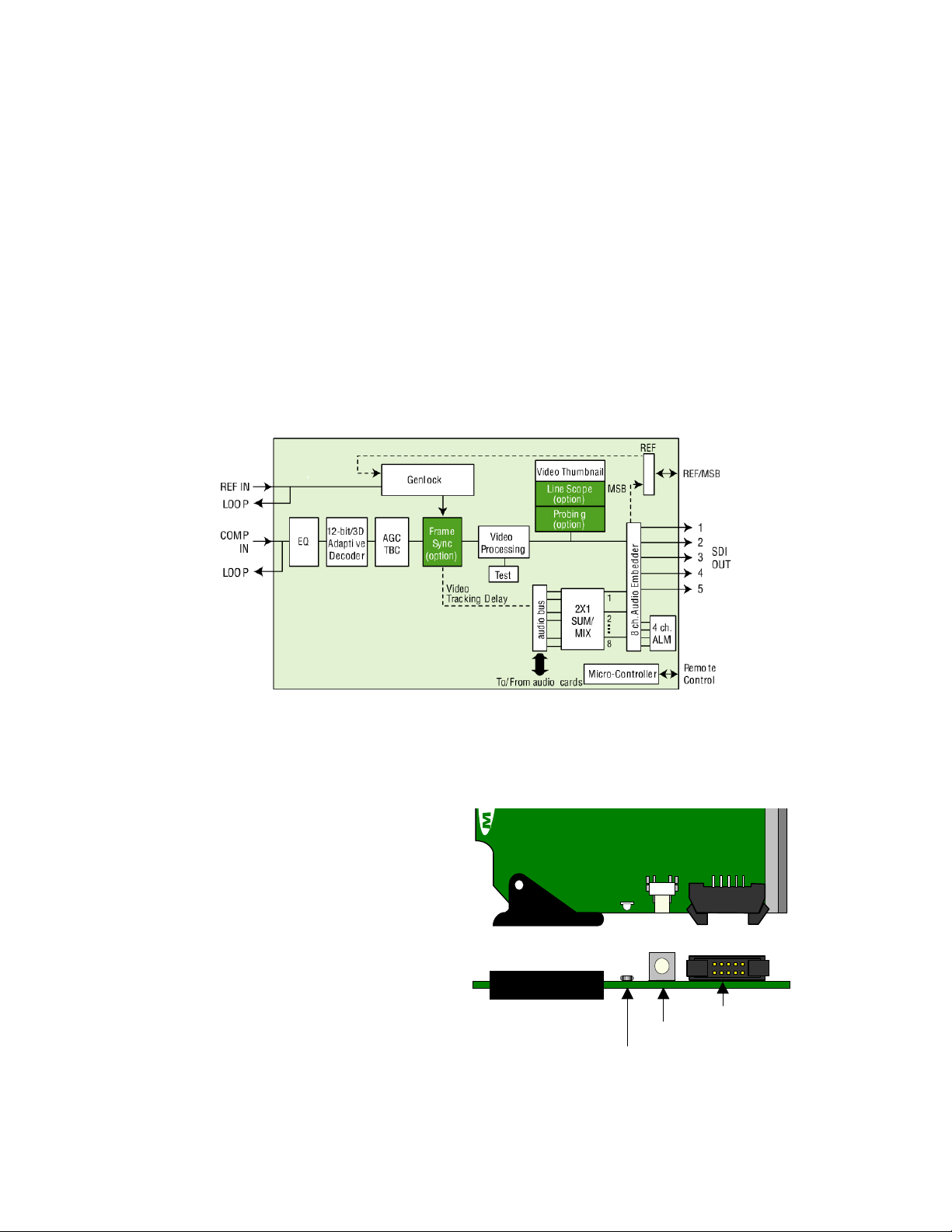
1.4 Functional Block Diagram
Figure 1.1 Functional block diagram DEC-1023
1.5 Front Card-edge Interface
The front card-edge of the DEC-1023 incorporates
three elements:
• Status LED (see section 3.2)
• Select Button (see section 3.3)
• ABUS connector (see section 2.3)
Figure 1.2 Front card-edge layout
ENC-1101
DEC-1023
Select
Status
ABUS connector
SELECT button
Status LED
2 | DEC-1023
Page 7
GUIDE TO INSTALLATION AND OPERATION
2 Installation
2.1 Unpacking
Make sure the following items have been shipped with your DEC-1023. If any of the following items are
missing, contact your distributor or Miranda Technologies Inc.
• DEC-1023 12-Bit Composite to SDI Decoder
• DEC-10NN-DRP Double Rear Panel (see figure 2.2)
2.2 Installation in the Densité frame
The DEC-1023 must be mounted in a DENSITÉ frame. The installation includes both the DEC-1023 module,
and the rear panel module. It is not necessary to switch off the power from these frames when installing or
removing the DEC-1023.
When used in conjunction with an audio module such as the UAP-1781, the ABUS flat cable needs to be
installed between the ABUS connector of the DEC-1023 and the connector of the audio module. The ABUS
flat cable is supplied with the audio module.
Detailed instructions for installing cards and their associated rear panels in the Densité frame are given in the
Densité Frame manual.
When the double-width rear panel has been installed, the module must be installed in the right-most of the
two slots covered by the panel in order to mate with the rear panel connectors. Should it be installed in the
wrong slot, the front panel LED will flash red. Move the card to the other slot for correct operation. No
damage will result to the card should this occur.
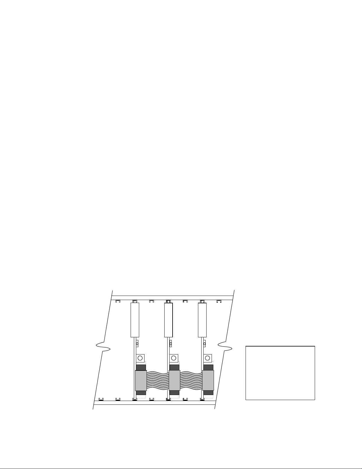
2.3 ABUS Connection to Companion Audio Cards
When the DEC-1023 is used in conjunction with one or two companion audio cards (Miranda’s AAP, DAP or
UAP series), the ABUS flat cable must be installed between the ABUS connector of the DEC-1023 and the
connectors on the audio cards. The ABUS flat cable is supplied with the audio card.
Figure 2.1 ABUS flat cable installation
DEC-1023
UAP-XXXX
DAP-XXXX
Note: If only one
audio card is used,
you must use the two
end connectors on the
ABUS cable, and
leave the center
connector unplugged
DEC-1023 | 3
Page 8
GUIDE TO INSTALLATION AND OPERATION
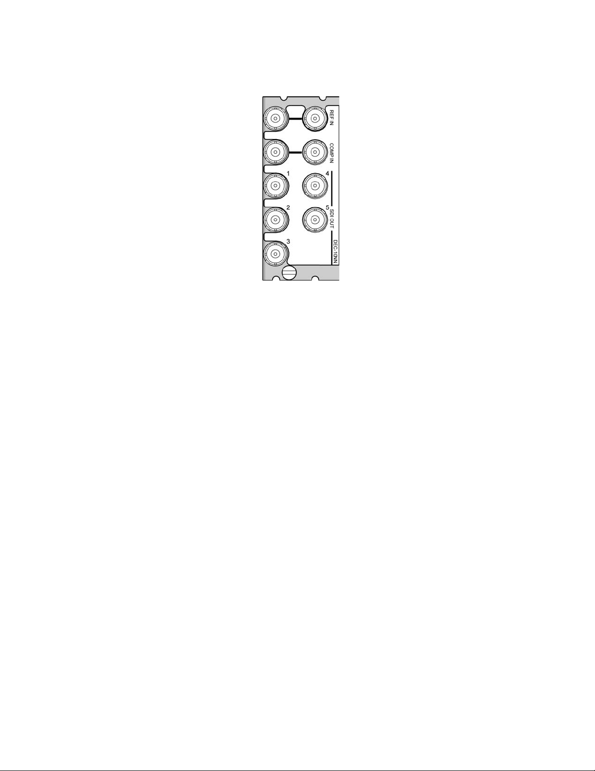
2.4 Rear Panel Connectors
Figure 2.2 DEC-10NN-DRP Rear Panel
REF IN – Studio reference input and loop-through
For external synchronization, connect a black studio reference signal to the BNC labeled REF IN.
The reference input must conform to SMPTE 170M/SMPTE 318M/ITU 624-4/BUT 470-6 for standard
definition signals, and should match the format of the composite input signal..
• The loop must be terminated if not used.
COMP IN – analog composite video input and loop-through
Connect an analog composite video signal – NTSC, PAL, PAL-M and SECAM are supported.
SDI OUT – serial digital video outputs (5)
The DEC-1023 provides five SD SDI video outputs on BNC connectors, labeled SDI OUT 1 through 5. The
SDI video signal conforms to the SMPTE 292M and SMPTE 259M-C standard.
4 | DEC-1023
Page 9

GUIDE TO INSTALLATION AND OPERATION
3 Operation
3.1 Control options
The DEC-1023 can be controlled in three different ways:
• The local control panel and its push-buttons can be u sed to move through a menu of parameters and to
adjust parameter values (see section 3.3).
• Miranda’s RCP-100 remote control panel can be used to access the same menu structure fro m a remote
location (see section 3.4).
• Miranda’s iControl system can be used to access the card’s operati ng parameters from a remote
computer, using a convenient graphical user interface (GUI). (see section 3.5)
3.2 Card-Edge Status LED
The status monitor LED is located on the front card-edge of the DEC-1023, and is visible through the front
access door of the DENSITÉ frame. This multi-color LED indicates the status of the DEC-1023 by color, and
by flashing/steady illumination.
The chart shows how the various error conditions that can be flag ged on the DEC-1023 affect the LED status.
• If a cell is gray, the error condition cannot cause the LED to assume that status
• If more than one LED status is possible for a particular error condition, the status is configurable.
See Section 3.5.15 for details.
• The factory default status is shown by a
• The error conditions that affect the LED status can be viewed on the Den sité fra me’s local control
panel. Push the Status button on the front of the card and see the error message displayed.
For example:
See section 3.3 for more information.
The LED will always show the most severe detected error status that it is configured to display, and in the
chart error severity increases from left to right, with green representing no error/disabled, and flashing red the
most severe error.
D E C - 1 0 2 3
C H 1S I L E N C E
DEC-1023 | 5
Page 10
GUIDE TO INSTALLATION AND OPERATION
Error Condition
No rear panel
Hardware error
No SDI signal
No audio grp 1
No audio grp 2
No audio grp 3
No audio grp 4
Silence Ch. 1
Silence Ch. 2
Silence Ch. 3
Silence Ch. 4
Silence Ch. 5
Silence Ch. 6
Silence Ch. 7
Silence Ch. 7
Overload
Test
Card system
Green Yellow Red
LED Status
Flashing
Red
: Factory default.
If the LED is Flashing Yellow, it means that the card is selected for local control using the Densité frame’s
control panel. See Section 3.3 for details.
3.3 Local control using the Densité frame control panel
3.3.1 Overview
Push the SELECT button on the DEC-1023 card edge (see Section 1.5) to assign the local control panel to
operate the DEC-1023. Use the control panel buttons to navigate through the menu, as described below.
All of the cards installed in a Densité frame are connected to the frame’s controller card, which handl es all
interaction between the cards and the outside world. There are no operating controls located on the cards
themselves. The controller supports remote operation via its Ethernet ports, and local operation using its
integrated control panel.
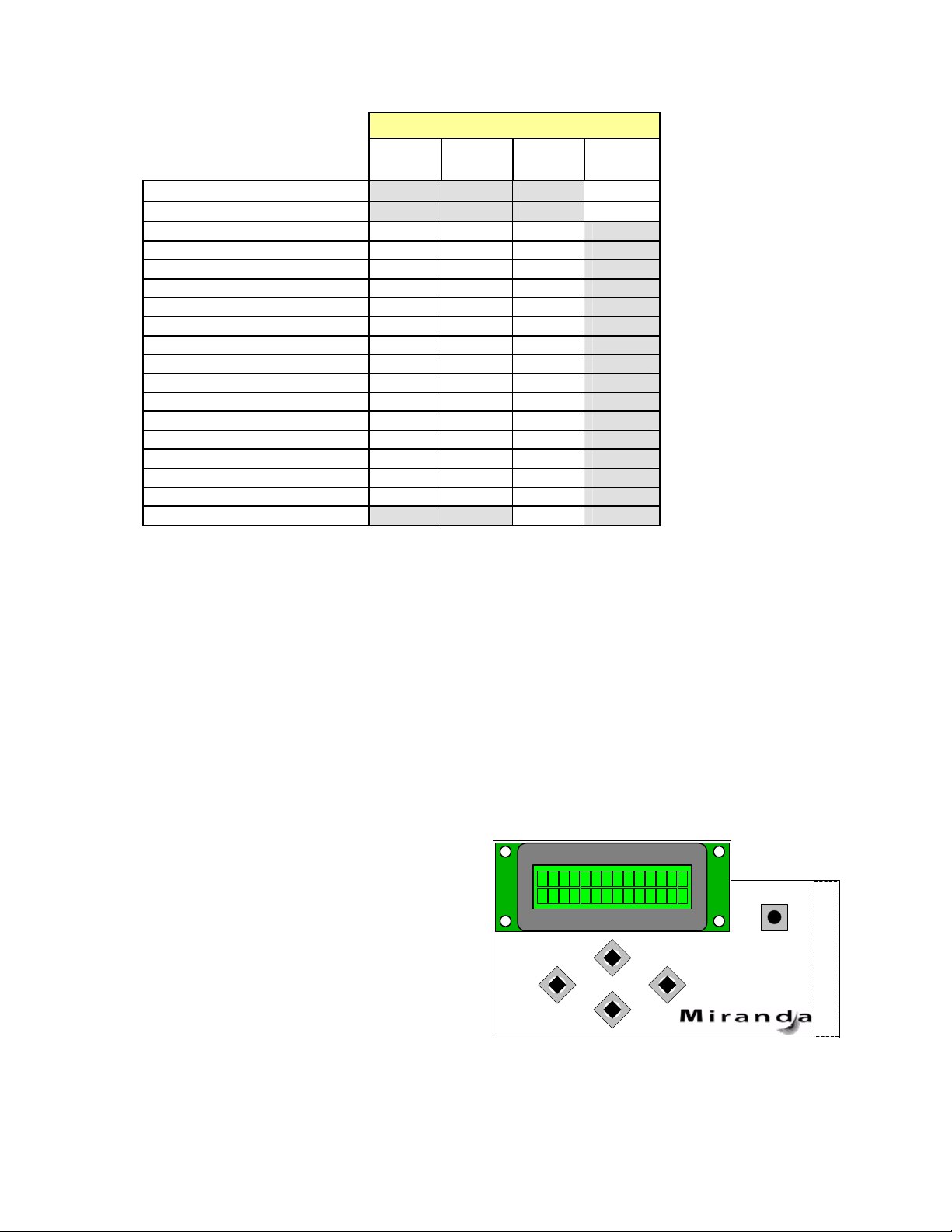
The local control panel is fastened to the controller
card by a hinged connector, and when installed is
located in the front center of the frame, positioned in
front of the power supplies. The panel consists of a
display unit capable of displaying two lines of text,
each 16 characters in length, and five pushbuttons.
The panel is assigned to operate any card in the
frame by pushing the SELECT button on the front
edge of that card.
• Pushing the CONTROLLER button on the control panel select s the Controller card itself.
CONTROLLER
ESC
+
-
SELECT
Figure 3.1 Densité Frame local control panel
6 | DEC-1023
Page 11

GUIDE TO INSTALLATION AND OPERATION
• The STATUS LED on the selected card flashes yellow.
The local control panel displays a menu that can be navigated using the four pushbuttons located beneath
the display. The functionality of the pushbuttons is as follows:
[+] [–] Used for menu navigation and value modification
[SELECT] Gives access to the next menu level. When a parameter value is shown, pushing this button
once enables modification of the value using the [+] and [–] buttons; a second push confirms the
new value
[ESC] Cancels the effect of parameter value changes that have not been confirmed; pushing [ESC]
causes the parameter to revert to its former value.
Pushing [ESC] moves the user back up to the previous menu level. At the main menu, [ESC]
does not exit the menu system. To exit, re-push the [SELECT] button for the card being
controlled.
If no controls are operated for 30 seconds, the controller reverts to its normal standby status, and the
selected card’s STATUS LED reverts to its normal operating mode.
3.3.2 Menu for local control
The DEC-1023 has operating parameters which may be adjusted locally at the controller card interface.
• Press the SELECT button on the DEC-1023 front card edge to assign the Densité frame’s local
control panel to the DEC-1023
• Use the keys on the local control panel to step through the displayed menu to configure and adjust
the DEC-1023.
The complete menu structure is shown in the Annex to this document, beginning on page 35.
3.4 Remote Control Using the RCP-100
The DEC-1023 can be controlled through a menu accessible using Miranda’s RCP-100 remote control panel.
Please refer to the RCP-100 Guide to Installation and Operation for detailed instructions on installing and
operating the RCP-100, and for instructions on how to connect the RCP-100 to the DEC-1023 (or any other
supported card) so that the menu can be accessed.
3.5 Remote control using iControl
The operation of the DEC-1023 may be controlled using Miranda’s iControl system.
• This manual describes the control panels associated with the DEC-1023 and th eir use.
• Please consult the iControl User’s Guide for information about setting up and operating iControl.
In iControl Navigator or iControl Websites, double-click on the DEC-1023 icon to open the control panel.
DEC-1023 | 7
Page 12
GUIDE TO INSTALLATION AND OPERATION
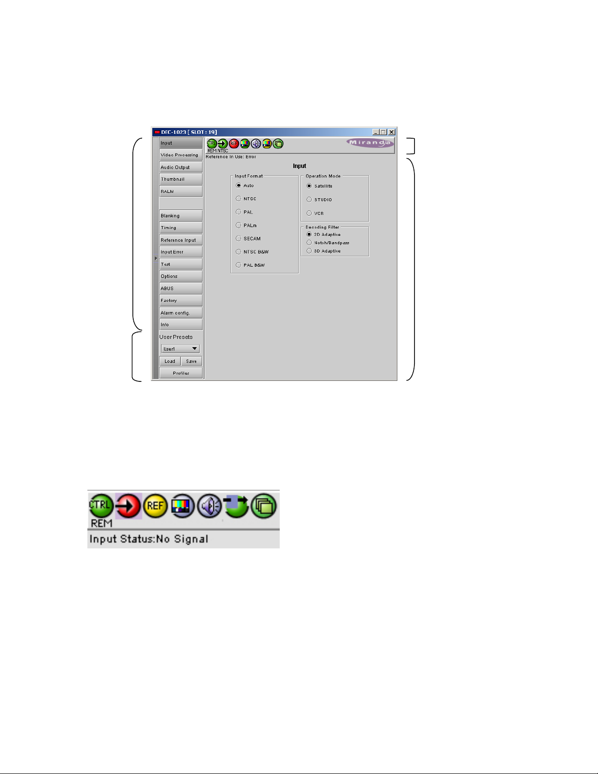
3.5.1 The iControl graphic interface window
The basic window structure for the DEC-1023 is shown in figure 3.2. The window identification line gives the
card type (DEC-1023) and the slot number where the card installed in its Densité frame.
Figure 3.2 DEC-1023 iControl graphic interface window:
There are four main sections in the window itself, identified in figure 3.2:
1. The top section displays icons on the left. These icons report different statuses such as card
communication status, input signal and reference signal format and statuses. In some instances, they relate
to conditions defined through parameters settings.
Icon # 1 2 3 4 5 6 7
Move the mouse over an icon and a status message appears below the icon providing additional information.
If there is an error, the error status message appears in the message area without mouse-over.
• If there are multiple errors, the error messages cycle so all can be seen
• The icon whose status or error message is shown is highlighted with a mauve background
The table below lists the various status icons that can appear, and how they are to be interpreted.
• In cases where there is more than one possible interpretation, read the error message in the i Control
window to see which applies.
8 | DEC-1023
Page 13
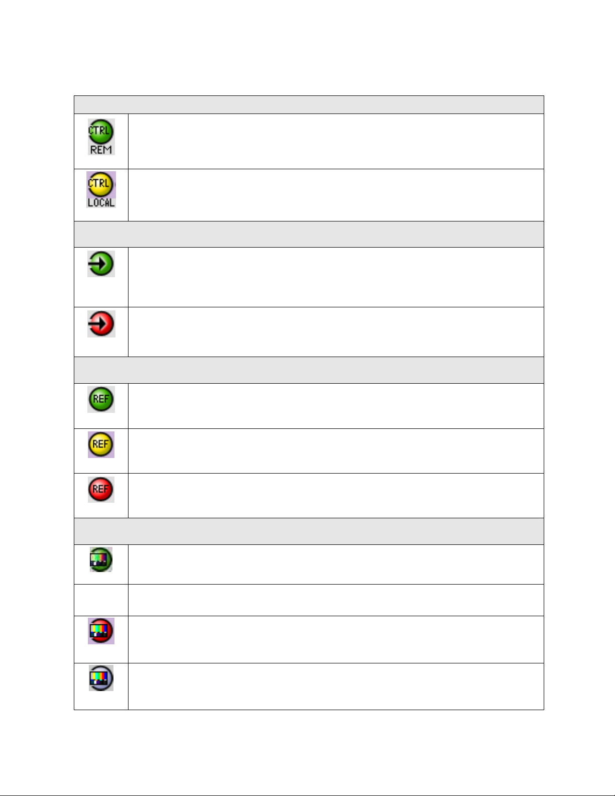
Table –iControl Status Icon interpretation
Icon #1 – Manual Card Configuration
Remote card control activated. The iControl interface can be used to operate the card
(green)
Local card control active, The card is being controlled using the Densité frame control
panel, as described in section 3.3. Any changes made using the iControl interface will have
(yellow)
no effect on the card.
Icon #2 – Input status
Signal detected and valid.
(green)
• Beneath the icon, the format will be indicated, and the specific format details will
be listed if the cursor is moved over the icon.
Signal absent
No rear
(red)
Reference mismatch
GUIDE TO INSTALLATION AND OPERATION
Icon #3 – Reference
Reference signal detected and valid
(green)
Input signal used as reference
(yellow)
Reference absent
(red)
Icon #4 – Video alarms status
Video OK
(green)
(yellow)
Error
(red)
(gray)
All video disabled
DEC-1023 | 9
Page 14

GUIDE TO INSTALLATION AND OPERATION
Icon #5 – Audio alarms status
Audio OK
(green)
Non-PCM audio detected on 1 or more channels
(yellow)
All audio disabled
(gray)
Icon #6 – Video/Audio Test
Operation mode: process – normal processing of the input signal – test signals OFF
(green)
Operation mode: TEST – color bar enabled (see Sect.3.5.11)
(yellow)
Operation mode: TEST – audio test tones enabled (see Sect.3.5.11)
(yellow)
Operation mode: TEST – color bar and audio test tones enabled (see Sect.3.5.11)
(yellow)
Icon #7 – ABUS Multiple card configuration / presence
OK – detected card configuration matches configuration set in the ABUS control panel
(green)
Card System Mismatch – the audio cards detected on the ABUS do not match the
configuration selected in the ABUS panel
(red)
2. The left portion of the window contains all the parameter groups, which become h ighlighted when they
are selected; the main panel (4) then displays the group’s set of parameters. Each of the groups is described
in detail below.
3. The lower left corner of the window contains the controls for use r presets.
4. The main panel contains all the parameters specific to the group selected. It may contain several tabs to
help manage the different parameters.
10 | DEC-1023
Page 15

GUIDE TO INSTALLATION AND OPERATION
The Main Window shows all controls, adjustments and information pertaining to the area of interest which
appears as a title to the panel, corresponding to the selection button to the left of the control panel.
In many cases, controls are provided to configure the DEC-1023’s features. Types of controls that may be
found are:
Slider:
The current value is displayed beneath the center of the slider bar (e.g. 39 in the example shown). To
change the value, move the slider by clicking and dragging it, or by clicking the arrow icon at either end.
Slider with data box:
The current value is displayed in the data box at the right hand side (e.g. 50 in the example shown). To
change the value, move the slider by clicking and dragging it, or by clicking the arrow or double-arrow icon at
either end, or type a new value directly into the data box, and hit “enter” from your keyboard. If you enter a
value outside the permitted range (as shown beneath the slider), the data box wil l flash red and the value will
not be changed.
Pull-down list:
The current selection is shown on the icon. To change it, click on the down arrow at the right of the box, and
click on the desired option in the list that appears below the box.
Check box (with label):
A selected box has a checkmark in it, as shown in the example, while an unselected box is blank. Click on
the box to change its status.
Each of the panels associated with the groups accessed from the buttons in Section 2, and shown in Section
4, is described individually in the following sections.
3.5.2 Input
DEC-1023 | 11
Page 16

GUIDE TO INSTALLATION AND OPERATION
This group allows input selection, operation mode
selection, and selection of the decoding filter. See
figure 3.3.
INPUT FORMAT: Auto, NTSC, PAL, PALm,
SECAM, NTSC B&W, PAL B&W: Select the input
format using the radio buttons.
• When using AUTO, the DEC-1023 detects
the type of input and automatically switches
to that format by loading the decoder with
the format’s parameters.
• When working with monochrome input
signals, set the format to NTSC B&W or PAL
B&W to accept a black and white input.
OPERATION MODE: Select an option based on
the nature of the input signal:
• STUDIO source type when using high
quality sources
• SATELLITE for satellite sources
Figure 3.3 Input group
• VCR for unstable sources.
DECODING FILTER: Select the decoding filter according to the nature of the input composite signal:
• 2D Adaptive for fast-moving images requiring optimum performance
• Notch/Bandpass for lower-quality sources
• 3D Adaptive for optimum performances with static patterns.
3.5.3
Video Processing
These controls allow the user to adjust some
parameters of the video encoded in the output SDI
signal.
ALL GAIN: -800, -799 …, 799, 800: Sets luma and
chroma gains to a specific value. When other gains
are individually set, ALL GAIN reflects the average
value of the combined gains for a given output
format.
LUMA GAIN: -800, -799 …, 799, 800: Sets luma
gain to a specific value.
CHROMA GAIN: -800, -799 …, 799, 800: Sets
chroma gain to a specific value.
HUE:-40, -39 …, 40: Sets hue to a specific value in
degrees.
BLACK LEVEL: -64, -63 …, 63, 64: In NTSC mode,
sets Black level to a specific value.
Figure 3.4 Video Processing group
12 | DEC-1023
Page 17

GUIDE TO INSTALLATION AND OPERATION
PEDESTAL: -5, -4.5 …, 9.5, 10 (525) / -27,-26 …, 106, 107 (625): sets a pedestal value in IRE units.
LENGTH: Using the UNIT checkbox, select either FEET or METER. FEET: 0, 1 …, 983, 984; METERS: 0, 1
…, 299, 300: Sets the frequency equalizer to compensate for the video signal’s high-frequency loss caused
by the cable length.
3.5.4 Audio Output
Enabled only when an optional audio card is in use via ABUS
When combined with up to two audio cards such
as the UAP-1781 Universal Audio Processor,
these parameters provide extended controls over
audio embedding.
CH 1-2, CH 3-4, CH 5-6, CH 7-8 tabs: each of
these tabs controls a pair of channels; each
channel is provided with a set of controls.
Operation Mode: Off, A, SUM (A+B), Mix:
Select the source of the signal that will be output
on this channel:
• Off: The output channel is muted.
• A: Output only the channel selected in the
Source A pulldown
• SUM (A+B): Output the sum of two channels
selected in the SOURCE A and SOURCE B
pulldowns. Use the SUM (A+B) Level
pulldown to apply an attenuation (–6 dB, -3
dB, 0 dB) to the summed output.
• Mix: Output a mono mix of two channels
Figure 3.5 Audio Output group – CH 1-2 tab
selected in the SOURCE A and SOURCE B
pulldowns.
• MUTE: click the checkbox to mute this channel.
Source A and Source B
ABUS Select: A1, A2: selects the external audio card to be used for this channel (A1 or A2).
Channel: Channel 1 …, Channel 16: selects the source channel to be used from the Audio Bus.
Level (dB): -96, -95 …, -1, 0: sets an attenuation Level for the selected source.
Note: SOURCE A and SOURCE B must be made available through Multiple Card Config in the ABUS
window (see page 15) before they can be used in this window.
Embedding tab
DEC-1023 | 13
Page 18

GUIDE TO INSTALLATION AND OPERATION
F
CH 1, 2, 3, 4 and CH 5, 6, 7, 8: use the pulldown list to
choose the AES audio groups in which audio channels 1
to 4 and 5 to 8 will be embedded.
Output – Audio Insert: use the pulldown to select whether
the inserted audio will be 20 bit or 24 bit
Figure 3.6 Audio Output group – Embedding tab
3.5.5 Thumbnail
Thumbnails are used to monitor the video output
signal of the DEC-1023. Streaming parameters
are set using these controls.
Status Display (optional with activation of the
probing option)
On the left side of the panel is a display of the
current status of the parameters measured by the
probe. Two separate status columns are shown:
Current status shows the status
now. Latched status shows the
status as affected by latching.
When an error is detected, it is
flagged in both columns by turning
red. When the error disappears, the
current status returns to green.
However, the Latched status shows
the error until it is manually cleared
using the Reset Latched button
beneath the status monitors. You
can also reset the Current status,
to confirm the presence of
displayed errors. Only those
parameters that have been enabled are reported in the current status list; the others show a
gray status box and their names are grayed in the list.
igure 3.7 Thumbnail group – Connection tab
14 | DEC-1023
Page 19

GUIDE TO INSTALLATION AND OPERATION
CONNECTION sub-tab:
ENABLE: OFF, VIDEO: enables thumbnail streaming or turns streaming OFF
SIZE: SMALL, MEDIUM, LARGE: selects the size of the Thumbnail image.
PLAYER: OFF, THUMBNAIL: Click on the Thumbnail box to enable the thumbnail Player. A window opens in
the top section and shows a thumbnail associated with the SDI video stream that is being encoded by the
DEC-1023.
• Note: you must check the VIDEO box in the ENABLE section to see the video image.
QUALITY: Use the left-hand pulldown to select the video quality to be sent by the streaming encoder.
• The choices are Poor, Normal and HiQ (e.g. high quality).
REFRESH RATE: Use the right-hand pulldown to select the refresh rate for the transmitted thumbnails.
• The choices are Fast, 1 sec, 2 sec …, 10 sec.
Streaming Priority Control: Click the Take control from Slot [##] checkbox to force the Densité Controller for
this frame to assign more bandwidth for this card’s streaming output. Only one card in the frame can use this
feature. It has no effect unless you have selected Fast for the refresh rate. The actual slot number of this
card, as shown in the window title bar, will appear when the checkbox is ticked.
VIDEO PROBE tab:
The Video Probe tab is only available if the
probing options have been enabled via the
activation code in the options tab (p. 24).
This control panel allows the user to establish
conditions under which errors will be flagged and
reported by the video probe feature. The top error
parameter in the list is selected when you open the
view, indicated by the darker color of its name box.
To select any other parameter, click on it.
Figure 3.8 Thumbnail group – Video Probe tab
To the right of the parameter list appear all the controls necessary to configure the selected parameter.
The parameter configuration panel usually includes, from top to bottom:
Enable: a checkbox to enable the alarm associated with this parameter
Threshold: a threshold value for detection of an error. The error will be detected when the measured
parameter falls above (or below, depending on the nature of the parameter) the indicated threshold value.
The values are those of the equivalent analog signal. In most cases this is a slider with data entry box.
Below the THRESHOLD slider are found slider bars allowing the configuration of the conditions under which
a detected error is flagged and reported. These conditions are set independently for each error type:
• ERROR DURATION: the length of time during which a parameter is allowed to be out-of-tolerance
without being identified as an error. This is useful for situations such as a hard switch or patch of a
video signal where there is a discontinuity in the signal which the user has deliberately caused and
does not need to be flagged as an error. If a parameter is continuously out of tolerance for the
specified duration, then an error is considered to have been detected. However, this error will not be
DEC-1023 | 15
Page 20

GUIDE TO INSTALLATION AND OPERATION
flagged (causing the status LED to change color and an error message to be sent out on the frame’s
interface) until the OCCURRENCE / DETECTION WINDOW conditions have been satisfied.
(Range: 0 to 90 seconds)
• OCCURRENCE: the number of times that a detected error is allowed to occur in a specified
DETECTION WINDOW before an error flag is set, and the error is reported (status LED changes color,
and message sent on the interface)
(Range: 1 to 16)
• INTERVAL: the time duration during which errors are counted to determine if the error flag should be
set. This is a moving window, e.g. the previous 2 minutes, and only errors falling within that window are
counted.
(Range: 1 min to 24 hours)
In most cases, all three conditions are defined:
In some cases, a different set of controls is available.
The following chart shows the controls for each error type..
White Max: Detects whether the maximum
luminance level of the input video signal is too high
by verifying if it does not rise above a specified
threshold.
ENABLE: check to enable this test.
THRESHOLD: set the level (in IRE or mV) above
which this condition will be flagged
Luma Min expected: Detects whether the video
signal contains some nearly-black information by
verifying if the Luma component of the video signal
includes information below a specified threshold.
ENABLE: check to enable this test.
THRESHOLD set the level (in IRE or mV) below
which this condition will be flagged
Luma Max expected: Detects whether the video
signal contains some nearly-white information by
verifying if the Luma component of the video signal
includes information above a specified threshold.
ENABLE: check to enable this test.
THRESHOLD: set the level (in IRE or mV) above
which this condition will be flagged
16 | DEC-1023
Page 21

Chroma Max: Detects whether the amplitude of the
chroma information in the video signal is too high by
verifying if the peak chrominance of the input video
signal is less than a specified threshold.
ENABLE: check to enable this test.
THRESHOLD: set the level (in %) above which this
condition will be flagged
Freeze Detection: Detects whether a sequence of
video frames are identical by verifying if it has been
detected on the input signal, taking account of
noise.
ENABLE: check to enable this test.
VALUE: select an image quality to be used as a
reference in determining whether the current image
is frozen. Choices are Noisy, Normal and HiQ.
GUIDE TO INSTALLATION AND OPERATION
Black Detection: Detects whether a sequence of
video frames contains only black on the input
signal.
ENABLE: check to enable this test.
THRESHOLD: set the level (in IRE or mV) below
which this condition will be flagged
CC Validity: Detects the validity of Closed
Captioning (CC) information in the VBI of the input
video signal.
ENABLE: check to enable this test
IMMEDIATE PRESENCE STATUS: shows the
current status of CC; green for present, and red for
absent.
ALARM CONFIG: use the slider to set the Error
Duration; the period during which CC must be
continuously absent before the CC Presence error
will be flagged
DEC-1023 | 17
Page 22

GUIDE TO INSTALLATION AND OPERATION
Close Caption: Detects the presence of Closed
Captioning (CC) information in the VBI of the input
video signal.
ENABLE: check to enable this test.
IMMEDIATE PRESENCE STATUS: shows the
current status of CC – green for present, and red for
absent.
DISPLAY CC, DISPLAY XDS: Enables the parsing
and the display of the Closed Captioning and the
XDS.
ALARM CONFIG: use the slider to set the Error
Duration; the period during which CC must be
continuously absent before the CC Presence error
will be flagged
VITC Presence: Detects the presence of the input
Time Code from a predetermined input line.
ENABLE DETECTION: check to enable this test
IMMEDIATE PRESENCE STATUS: show the
current status of VITC – green for present, and red
for absent.
LINE: Determines the input line monitored for the
Time Code detection.
HELP tab:
Gives additional information on each of the parameters
measured by the Video Probe. Click on the pull down
box at the top of the panel to select the desired
parameter.
Figure 3.9 Thumbnail group – Help tab
18 | DEC-1023
Page 23

3.5.6 RALM
Click on the RALM button at the left side of the
DEC-1023 control panel to open this view in the
main window.
The Real-time Audio Level Meter (RALM) visually
displays the status of each audio channel present.
Channels are displayed in pairs, so up to four
meters will be present in the meter display window.
The top section of the window shows a Status
Reporting section on the left, and the audio level
meters on the right.
Status reporting
The Status display shows the status of the functions
monitored by the Audio Probing function of the DEC1023 (Optional).
Current status shows the
status now.
Latched status shows the
status as affected by
latching. When an error is detected on a channel, it’s flagged in both sections by
turning red. When the error disappears, the current status returns to green but the
latched status stays marked as an error. Both statuses can be manually cleared by
using the reset button. Only the parameters that have been enabled are reported in
the current status list; the others are grayed out. Each alarm node monitors a channel
(from 1 to 8).
Audio meters
GUIDE TO INSTALLATION AND OPERATION
Figure 3.10 RALM group – RALM Connections tab
The meter display includes four double meters
Each meter is divided into three zones, and the dividing points and color of
each zone are individually configurable under the Meter Ballistics Config tab.
• The Overload Counter shows a running count of the number of overloads
detected. The Overload level is shown by a marker beside the mater, and
its position can be set under the Meter Ballistics Config tab
• The Phasemeter (located at the bottom of the RALM meter display) is a
small meter that represents the phase correlation factor between the two
channels of a pair.
Figure 3.11 RALM audio level meter
DEC-1023 | 19
Page 24

GUIDE TO INSTALLATION AND OPERATION
RALM CONNECTIONS tab: applies to local display in the iControl panel.
CH 1&2, CH 3&4, CH 5&6 and CH 7&8: audio
meters for each pair of channels may be turned
on (RALM) or OFF. Note: you need to check the
desired channels in the Audio Probe Remote
Control sub-section below in order to enable the
RALM button.
Reset counter: click this button to reset the
overload counter to zero.
Figure 3.12 RALM Connections tab
METER BALLISTICS CONFIG tab:
TYPE pull-down box: this pull-down offers a list of
the available meter types, whose ballistics are
identified by the standard to which they conform.
UPPER ZONE LIMITS (dB): select the crossover
level between the upper and middle zones of the
Figure 3.13 Meter Ballistics Config tab
meter (the range of values shown in the pull-down
list depends on the type of meter selected)
LOWER ZONE LIMITS (dB): select the crossover level between the middle and lower zones of the meter
(the range of values shown in the pull-down list depends on the type of meter selected)
COLOR SAMPLES: the three samples show the current selected color for the upper, middle and lower
zones of the meter. Click on the color sample of a zone to open a color selection panel to choose a
different color for that zone.
OVERLOAD CURSOR (dB):The overload cursor appears on the meter as an arrowhead in the meter
scale. The two pulldown boxes set the position of the overload cursor on the left and right meters (the
range of values shown in the pull-down list depends on the type of meter selected).
AUDIO PROBE tab:
This control panel allows the user to establish conditions
under which errors will be flagged and reported by the
Audio probe feature. The top error parameter in the list is
selected when you open the view, indicated by the darker
color of its name box. To select any other parameter, click
on it.
The error parameter list includes:
• SILENCE
• MIN. LEVEL
• MAX. LEVEL
• OVERLOAD
Figure 3.14 Audio Probe tab
To the right of the parameter list appear all the controls necessary to configure the selected paramete r.
• Sub-tabs give access to the audio channels in pairs (1&2, 3&4, 5&6, 7&8)
• The values are independently configurable for each channel
20 | DEC-1023
Page 25

GUIDE TO INSTALLATION AND OPERATION
The controls for all of these error types are identical (see figure 3.14), except for the threshold range
available. Each set of controls contains these elements:
Enable: a checkbox to enable the alarm associated with this parameter
Threshold: a threshold value for detection of an error. The error will be detected when the measured
parameter falls above (or below, depending on the nature of the parameter) the indicated threshold value. In
most cases this is a slider with data entry box.
Below the THRESHOLD slider are found controls for configuring the conditions under which a detected error
is flagged and reported. These conditions are set independently for each error type::
• ERROR DURATION: the length of time during which a parameter is allowed to be out-of-tolerance
without being identified as an error. This is useful for situations such as a hard switch or patch of a
video signal where there is a discontinuity in the signal which the user has deliberately caused and
does not need to be flagged as an error. If a parameter is continuously out of tolerance for the
specified duration, then an error is considered to have been detected. However, this error will not be
flagged (causing the status LED to change color and an error message to be sent out on the frame’s
interface) until the OCCURRENCE / DETECTION WINDOW conditions have been satisfied.
(Range: 0 to 90 seconds)
• OCCURRENCE: the number of times that a detected error is allowed to occur in a specified
DETECTION WINDOW before an error flag is set, and the error is reported (status LED changes color,
and message sent on the interface)
(Range: 1 to 16)
• INTERVAL: the time duration during which errors are counted to determine if the error flag should be
set. This is a moving window, e.g. the previous 2 minutes, and only errors falling within that window are
counted.
(Range: 1 min to 24 hours)
LOCKS tab: allows the user to lock the alarm settings for pairs of audio channels, e.g. 1& 2, 3&4.
HELP tab: gives the user basic information on the different audio parameters
.
• Use the pulldown to select the error type
3.5.7 Blanking
This panel provides control over VBI data handling.
VBI: PROCESS, PASS, BLANK, LINE BY LINE: select whether the overall VBI data field will be processed,
will pass or be blanked. If Line by Line is selected, use the right-side panel to set each line individually.
LINE BY LINE: Available when Line by Line is checked in the previous section. Radio buttons allow the
selection of conditions for each line of the VBI data field.
DEC-1023 | 21
Page 26

GUIDE TO INSTALLATION AND OPERATION
CC (525) / WSS (625): if CC or WSS data are
present in the signal, you may check this box to
allow this data to pass-through unaffected.
Figure 3.15 Blanking group
3.5.8 Timing
These controls provide access to timing adjustments
which affect the signal outputs. There are two slider
controls, each with a data reporting box which
shows the current value, and into which values can
be typed directly. If the Frame Sync option is not
enabled, only the Horizontal delay may be
accessed.
VERTICAL (Lines): 0, 1 …, 523, 524 (for 525
operation), 623, 624 (for 625 operation): sets the
number of lines for vertical delay. This control is
available when the Frame Sync option has been
activated (see Options tab).
HORIZONTAL (µs): 0, 0.037,0.064 …, 63.5 (for 525
operation) …,64 (for 625 operation): sets the
horizontal delay in µs.
FRAME DELAY Pulldown box: sets delay by frame
steps: 0, 1 or 2 frames. This control is available
when the Frame Sync option has been activated
(see Options tab p.24).
Figure 3.16 Timing group
22 | DEC-1023
Page 27

3.5.9 Reference Input
These controls allow selection of the reference
signal.
REFERENCE SOURCE: Select between AUTO,
EXTERNAL (use the REF input signal connected to
the rear panel), URS (see below) or INPUT (use the
input video signal as reference) as the reference
source. AUTO mode searches for available signal
in this order: REF input, URS and finally video input
signal.
1
URS
FORMAT: Select between OFF, 525 or 625
for the Universal Reference Signal format.
GUIDE TO INSTALLATION AND OPERATION
Figure 3.17 Reference group
3.5.10 Input Error
These controls set card behavior when an input
error is detected:
• KILL – kill the output
• BLACK – generate a video black at the
output
• FREEZE – freeze the last video frame before
the error was detected
• BYPASS – pass the input through as
received.
Figure 3.18 Input Error group
1
The URS is a single signal that distributes a frequency reference and frame alignment references for all video and audio signals to all
cards in a Densité frame.
DEC-1023 | 23
Page 28

GUIDE TO INSTALLATION AND OPERATION
3.5.11 Test
Use these controls to place test signals at the video
and/or audio outputs
VIDEO: check the box to select a 75% color bar test
signal at the output.
AUDIO: an audio tone may be selected for each of
the 4 channel pairs. Check the box for the desired
channel pair.
Figure 3.19 Test group
3.5.12 Options
Three options are available for the DEC-1023:
• Frame Sync option (DEC-1023-OPT-FS)
• Line Scope over IP option (DEC-1023-OPT-LS)
• Probing option (DEC-1023-OPT-PR.
FRAME SYNC Option: activates the Frame Sync
functions on the DEC-1023.
To activate this option, you must obtain a licence
key from Miranda Technologies.
• Type the licence key in the Enter Key box
• Click Enable Option to enable additional
timing controls (see section 3.5.8 on page 22).
Figure 3.20 Options group – Frame Sync
24 | DEC-1023
Page 29

IP SCOPE Option: adds Waveform Monitor and
Vectorscope over IP functions to the DEC-1023.
To activate this option, you must obtain a licence
key from Miranda Technologies.
• Type the licence key in the Enter Key box
• Click Enable Option to activate the waveform
monitor and vector scope feature.
To view the waveform monitor and vector scope
data, use the Streaming Player that is provided with
the iControl software. Consult the iControl
documentation to learn more about the Streaming
Player.
• Click the ENABLE checkbox to enable the
transmission of waveform monitor and vector
scope data
• Use the slider to select the line that will carry
the data.
• The REFRESH RATE pulldown box selects
the desired refresh rate:
Fast, 1 sec, 2 sec, …, 9 sec, 10 sec.
PROBING Option: activates the audio and video
probing functions of the DEC-1023.
• Video probing: see Section 3.5.5 on page 14
• Audio probing: see Section 3.5.6 on page 19
To activate this option, you must obtain a licence
key from Miranda Technologies.
• Type the licence key in the Enter Key box
• Click Enable Option to enable probing
controls.
GUIDE TO INSTALLATION AND OPERATION
Figure 3.21 Options group – IP Scope
Figure 3.22 Options group - Probing
DEC-1023 | 25
Page 30

GUIDE TO INSTALLATION AND OPERATION
3.5.13 ABUS
When optional audio cards such as the UAP-1781
are used to provide audio signals for embedding in
the DEC-1023’s SDI output, the ABUS audio bus
links the audio cards and the DEC-1023. The ABUS
tab is used to instruct the DEC-1023 about the
presence of installed audio cards.
MULTIPLE CARD CONFIG: The indicators signal
the presence of appropriate audio cards installed in
the Densité frame.
Use the pulldown box and select your system’s
configuration.
• Video – only the input video signal is used,
and no audio will be embedded
• V/ A1 – audio from the external A1 card is
available for embedding in the DEC-1023
output
• Video / A1 / A2 – audio from both external
audio cards A1 and A2 is available for
embedding in the DEC-1023 output
.
Figure 3.23 ABUS group
3.5.14 Factory
The Factory tab contains a LOAD FACTORY button
and an Auto-Calibration mode button.
Load Factory: Clicking this button will reinstate all
default parameter values. The DEC-1023 Menu on
pages 4-6 shows the default value underlined
parameters.
Auto Calibration (Color Bar): If the video input is a
color bar signal, the DEC-1023 can perform an
automatic calibration of it’s decoder function.
• Connect a standard color bar signal to the
DEC-1023 video input
• Click Start to run the auto-calibration
procedure
for all
Figure 3.24 Factory group
26 | DEC-1023
Page 31

GUIDE TO INSTALLATION AND OPERATION
3.5.15 Alarm Configuration
This panel allows the alarm reporting of the DEC1023 to be configured. The panel opens in a new
window when the button is clicked, and can be
resized if needed.
The panel is organized in columns.
Status/Name
This contains an expandable tree listing all the
alarms reported by this DEC-1023 card.
• Each alarm name includes an icon that shows
its current status
• Some alarms may be text-only and the alarm
status is shown in the name and not by a
status icon (e.g. Input Format in Fig. 3.25)
The Overall alarm and GSM contribution columns
contain pulldown lists that allow the level of
contribution of each individual alarm to the alarm
named in the column heading to be set.
• If there is no arrowhead in the box, there is no
pulldown and the alarm is not userconfigurable
• Overall Alarm
This column allows configuration of the
contribution of each individual alarm to the Overall
Alarm associated with this card. The Overall Alarm
is shown in the upper left corner of the iControl
panel, and also appears at the bottom of the Status/Name column.
• GSM Contribution
This column allows configuration of the contribution of each individual alarm to the GSM Alarm Status
associated with this card. GSM is a dynamic register of all iControl system alarms, and is also an alarm
provider for external applications. The possible values for this contribution are related to the Overall alarm
contribution:
• If the Overall alarm contribution is selected as Disabled, the GSM alarm contribution can be set to any
available value
• If the Overall alarm contribution is selected as any level other than disabled, the GSM contribution is
forced to follow the Overall Alarm.
Figure 3.25 Alarm Configuration panel
DEC-1023 | 27
Page 32

GUIDE TO INSTALLATION AND OPERATION
Levels associated with these alarms:
The pulldown lists may contain some or all of the following options:
The alarm makes no contribution (black icon)
The alarm is of minor importance (yellow icon)
The alarm is of major importance (orange icon)
The alarm is of critical importance (red icon)
The alarm exists but has no effect (used for text and composite alarms)
Shortcut: if you click in one of the columns beside a major heading in the Status/Name colu mn (where
there is no pulldown shown), you will open an “invisible” pulldown that lets you assign a level to all alarms
in that section of the column simultaneously.
Log Events
iControl maintains a log of alarm events associated with the card. The log is useful for troubleshooting and
identifying event sequences. Click in the checkbox to enable logging of alarm events for each individual
alarm.
At the bottom of the window are several other controls
Copy to other cards
Click this button to open a panel that allows the alarm
configuration set for this card to be copied into other
DEC-1023 cards.
• The window shows other DEC-1023 cards
available through iControl
• Select one or more destination cards from the
list in the window by clicking in the checkboxes,
or all of them by clicking in the All checkbox
• Note that when you do a Copy Profile for this
card (see Sect. 3.5.18), the alarm configuration
is copied along with all the other settings.
Figure 3.26 Copy to other cards
28 | DEC-1023
Page 33

GUIDE TO INSTALLATION AND OPERATION
Get alarm keys
Click this button to open a save dialog where you can
save a file containing a list of all alarms on this card
and their current values, along with an Alarm Key for
each. The alarm keys are useful for system
integration and troubleshooting.
• The file is saved in Excel.csv format
OK, Apply, Cancel
• OK accepts the settings and closes the window once the card confirms that there are no errors.
• Apply accepts the settings, but leaves the window open
• Cancel closes the window without applying any changes, and leaves the previous settings intact.
Figure 3.27 Get alarm keys save dialogue
3.5.16 The Info group
The top two lines in this panel identify the model of
this DEC-1023, and the rear panel that is currently
installed.
When the DEC-1023 is included in an iControl
environment, certain information about the card
should be available to the iControl system. The user
can enter labels and comments that will make this
card easy to identify in a complex setup. This
information is entered into data boxes in the Info
control panel.
Label: type the label that is shown for this
DEC-1023 when it appears in iControl
applications
Short Label type the short-form label that iControl
uses in some cases (8 characters)
Source ID type a descriptive name for this DEC-
1023
Comments: type any desired text
The remaining data boxes show manufacturing information about this card.
Figure 3.28 Info group
DEC-1023 | 29
Page 34

GUIDE TO INSTALLATION AND OPERATION
Three buttons in the panel give access to other information.
• Details…: Reports the Firmware version, service version, and panel version for this card
Figure 3.29 Details window
• Advanced…: Shows the Miranda LongID for this card.
The Miranda LongID is the address of this DEC-1023in
the iControl network.
Figure 3.30 Advanced window
• Remote System Administration – opens the Joining Locators
data box, which lists remote lookup services to which this DEC1023 is registered.
Add: Force the iControl service for this DEC-1023 to register
itself on a user-specified Jini lookup service, using the
following syntax:
jini://<ip_address>
where <ïp_address> is the ip address of the server
running the lookup service
Figure 3.31 Joining Locators window
Remove: select one of the services listed in the window by clicking on it, and click Remove t o delete it
from the window.
30 | DEC-1023
Page 35

GUIDE TO INSTALLATION AND OPERATION
3.5.17 User Presets
The DEC-1023 has 5 memory registers which can hold user-defined parameter settings.
To save the current settings:
• Select the register to be used through the pull-down box at the bottom left corner of the control panel
(the current selection is shown).
• Click Save to store the current configuration in that register.
• The existing contents of the preset will be overwritten.
To recall a saved configuration:
• Select the register with the saved configuration using the pulldown box
• Click Load to configure the DEC-1023 with the recalled data
3.5.18 Profiles
This section provides the option to save and recover the entire card configuration (including user p resets if
desired) on an external disk, or to copy it to another DEC-1023 card.
Click on Profiles at the bottom left of the window to open the Profile Copy window.
DEC-1023 | 31
Page 36

GUIDE TO INSTALLATION AND OPERATION
Figure 3.32 Profile Copy for Card window
Copy profile from section
This line shows this DEC-1023 card, and identifies it by App server, Densité frame and slot number, card
type and firmware version.
The Profile column has a pulldown that allows you to select which profiles you will work with, and gives these
choices:
• Current, User1, User2, User3, User4, User5, All
The Select column includes a checkbox, preselected as checked, to confirm that you want to work with the
current card.
Save Profile to Disk…
Click this button to open a Save dialog allowing you to specify a file name and location to which the selected
profiles for this card will be saved.
Hint - It is a good idea to create a folder for these files, because they are not explicitly identified as DEC-1023
profiles, and will be difficult to find and identify if not clearly named and conveniently located.
• Click the save button once the name and location have been identified in the Save box
• If the file is saved correctly, the Transfer Status box on the right of the Copy profile from line will
indicate Succeeded against a green background
• If the file was not saved for some reason, the Transfer Status box to the right of the Copy profile from
line will indicate Failed against a red background
Restore profile from disk…
Click this button to open an Open dialog box within which you
can locate and select a valid DEC-1023 profile file.
• Click Open to read the contents of the file and to
reconfigure this DEC-1023’s profiles according to its
contents
32 | DEC-1023
Page 37

GUIDE TO INSTALLATION AND OPERATION
• While the reconfiguration is in progress, the Transfer Status box on the right of the Copy profile from
line will indicate Working against a yellow background
• When the reconfiguration is complete, the Transfer Status box on the right of the Copy profile from line
will indicate Succeeded against a green background
Copy profile to section
This line shows other DEC-1023 cards that are available on the iControl network, each identified by App
server, Densité frame and slot number, card type and firmware version.
The Profile column shows the same information as is shown for the current card in the Copy profile from line,
i.e.
• Current, User1, User2, User3, User4, User5, All
The Select column includes a checkbox to identify which DEC-1023 cards you wish to copy profiles into from
the current card.
• For convenience, a Select all checkbox is provided in the column header
Click Copy to copy the selected profiles from this card into the selected other DEC-1023 cards
• While the profile copy operation is in progress, the Transfer Status box on the right of the Copy profile
to line will indicate Working against a yellow background
• When the profile copy operation is complete, the Transfer Status box on the right of the Copy profile to
line will indicate Succeeded against a green background
DEC-1023 | 33
Page 38

GUIDE TO INSTALLATION AND OPERATION
4 Specifications
COMPOSITE IN with EQUALIZATION
SIGNAL: NTSC (525/60) SMPTE 170M
PAL (625/50) ITU-R BT470-6
PAL-M (525/60) ITU-R BT470-6
SECAM ITU-R BT470-6
with passive loop-through.
RETURN LOSS: > 35 dB up to 5.75 MHz
COUPLING: DC
LEVEL: 2Vpp max
IMPEDANCE: 75 Ohms bridging
EQUALIZATION : Match attenuation curves of Belden 8281 to 300m.
REFERENCE IN
SIGNAL: NTSC SMPTE 170M / PAL ITU-R BT470-6 reference black signal
with passive loop-through
RETURN LOSS: > 35 dB up to 5.75 MHz
SDI OUT
SIGNAL (5): SDI SMPTE 259M-C (270 Mbps) + SMPTE 272M-C
RETURN LOSS: > 15 dB up to 270 MHz
JITTER: < 0.2 UI (0.74ns) pp (WIDEBAND)
VIDEO PROCESSING PERFORMANCE
QUANTIZATION: 12 Bits
SAMPLING: 8fsc (2X oversampling)
FREQU. RESPONSE: ± 0.1 dB up to 5.5 MHz
NOISE (UNWEIGHTED): < -60 dB up to 5,75MHz
PROCESSING DELAY: 110 µs (min)
2T K FACTOR: < 0.5%
DIFFERENTIAL GAIN: < 0.5%
DIFFERENTIAL PHASE: < 0.5 degree
LNL: < 0.5%
MISCELLANEOUS
TEST GENERATOR: 75% color bars with
100% white bar
STORAGE TEMP.: -40 to 85 °C
OPERATING ENV.: 0 to 40 °C
POWER: 6.1W (Max current)
AUDIO EMBEDDING
DIGITAL STREAM: 8 audio signals embedded
Audio selectable (On/Off)
24 bits, 48 kHz, Synchronous
EMBEDDING: As per SMPTE-272M-C
34 | DEC-1023
Page 39

GUIDE TO INSTALLATION AND OPERATION
ANNEX – DEC-1023 User Interface
STATUS NO SIGNAL / NTSC / PAL / PAL-M / SECAM, NTSC B&W, PAL B&W
NO EXTERNAL REF / EXTERNAL REF 525 / EXTERNAL REF 625
NO URS / URS 525 / URS 625
REF MISMATCH
INPUT FORMAT ERR
NO REAR / DOUBLE REAR
OUTPUT : 525 / 625
TEST ON
A1 MISSING
A2 MISSING
CARD SYSTEM
HARDWARE FAILURE
USER PRESET LOAD [USER 1 ,USER 2, USER 3, USER 4, USER 5]
SAVE [USER 1 ,USER 2, USER 3, USER 4, USER 5]
INPUT FORMAT [AUTO
OPERATION MODE [SATELLITE, STUDIO
DECODING FILTER [2D ADAPTIVE
CC [OFF
WSS [OFF
AUTO CALIBRATE START O.K / NO GOOD
VIDEO PROC ALL GAIN [-800, -799, …0
LUMA GAIN [-800, -799, …0
CHOMA GAIN [-800, -799, …0
HUE [-40, -39,…0
BLACK LEVEL [-64, -63, ..,0
PEDESTAL [-5, -4.5, …0
[-27, -106, …0
EQ [NONE
[NONE
EQ UNITS [METERS
, NTSC, PAL, PAL-M, SECAM, NTSC B&W, PAL B&W]
, VCR]
, NOTCH / BANDPASS, 3D ADAPTIVE]
, ON]
, ON] (625)
…799, 800]
…799, 800]
…799, 800]
, …. 39, 40]
, …, 63, 64]
…9.5, 10] (IRE) (NTSC / PAL-M)
…106, 107] (PAL / SECAM)
, 1, 2, …, 300] (meters)
, 3, 6, …, 984] (feet)
, FEET]
(525)
DEC-1023 | 35
Page 40

GUIDE TO INSTALLATION AND OPERATION
AUDIO EMBEDDING CHANNELS 1234 TO [OFF, GRP 1, GRP 2, GRP 3, GRP 4]
* Available with Audio
Card connected
OUTPUT MIXERS CHANNEL 1 OPERATION MODE [OFF, A, SUM(A+B), MIX]
CHANNEL 2 OPERATION MODE [OFF, A
ABUS [A1
CHANNEL SELECT [1
LEVEL [-96, -95, …. 0]
MUTE [OFF
CHANNEL 3 OPERATION MODE [OFF, A, SUM(A+B
SOURCE A ABUS [A1
CHANNEL SELECT [1
SOURCE B ABUS [A1
CHANNEL SELECT [1
SUM (A+B) LEVEL -6, -3
MUTE [OFF
CHANNEL 8 OPERATION MODE [OFF, A, SUM(A+B), MIX]
SOURCE A ABUS [A1
CHANNEL SELECT [1
LEVEL [-96, -95, …. 0]
SOURCE B ABUS [A1
CHANNEL SELECT [1
LEVEL [-96, -95, …. 0]
MUTE [OFF
BLANKING VBI (10-20) [PASS
VBI (6-22) [PASS,
CHANNELS 5678 TO [OFF, GRP 1, GRP 2
, BLANK, PROC, DECOD, USER]
BLANK, PROC, DECOD, USER]
, GRP 3, GRP 4]
, SUM(A+B), MIX]
, A2]
, 2, 3, …. 16]
(dB)
/ ON]
), MIX]
, 0 dB
/ ON]
/ ON]
(DEC-1023 525)
(DEC-1023 625)
, A2]
, 2, 3, …. 16]
, A2]
, 2, 3, …. 16]
, A2]
, 2, 3, …. 16]
, A2]
, 2, 3, …. 16]
(dB)
(dB)
INPUT LOSS [KILL
TIMING FRAME DELAY [0
VERTICAL [0
[0
HORIZONTAL [0
[0
, BLACK, FREEZE FIELD, PASS] * Available with Frame Sync Option
36 | DEC-1023
, 1, 2] * Available with Frame Sync Option
, 1, 2, …. 523, 524] (lines) (525) * Available with Frame Sync Option
, 1, 2, …. 623, 624] (lines) (625) * Available with Frame Sync Option
, 0.037, 0.064, …. 63,5] (us) (525)
, 0.037, 0.064, …. 64] (us) (625)
Page 41

GUIDE TO INSTALLATION AND OPERATION
REFERENCE SOURCE [AUTO, EXTERNAL, URS, INPUT] * Available with Frame Sync Option
URS FORMAT [OFF
CARD SYSTEM [NONE
TEST VIDEO [OFF
AUDIO CH 1&2 [OFF
AUDIO CH 3&4 [OFF
AUDIO CH 5&6 [OFF
AUDIO CH 7&8 [OFF
CONFIG ALARMS NO SIGNAL ALARM LEVEL [GREEN, YELLOW, RED
ALARM REPORT [NONE
REF MISMATCH ALARM LEVEL [GREEN, YELLOW, RED
ALARM REPORT [NONE
NO REF ALARM LEVEL [GREEN, YELLOW, RED
ALARM REPORT [NONE
INPUT FORMAT ERR ALARM LEVEL [GREEN, YELLOW, RED
ALARM REPORT [NONE
TEST ALARM LEVEL [GREEN, YELLOW
ALARM REPORT [NONE
CARD SYSTEM ALARM LEVEL [GREEN, YELLOW, RED
ALARM REPORT [NONE
VERSION DEC-1023: xxx
OPTIONS LINE SCOPE ON/OFF Key: xx.xx.xx.xx
FRAME SYNC ON/OFF Key: xx.xx.xx.xx
VIDEO PROBING ON/OFF Key: xx.x x.xx.xx
FACTORY DEFAULT [RESTORE]
, A1, A1 + A2]
, 525, 625] * Available with Frame Sync Option
/ ON]
/ ON] * Available with Audio Card connected
/ ON] * Available with Audio Card connected
/ ON] * Available with Audio Card connected
/ ON] * Available with Audio Card connected
, FLASH RED]
, GPI]
, FLASH RED]
, GPI]
, FLASH RED]
, GPI]
, FLASH RED]
, GPI]
, RED, FLASH RED]
, GPI]
, FLASH RED]
, GPI]
DEC-1023 | 37
 Loading...