

Page 1
Production Switchers
DD35 Family
Seraph HD
Operating Instructions
Release V 3.1.5
Page 2

Published by
BTS Media Solutions GmbH
Brunnenweg 9
D-64331 Weiterstadt, Germany
P.O. Box 1165
Tel: +49 (0) 6155-870-0
Fax: +49 (0) 6155-870-300
Copyrights
Für diese Unterlage behalten wir uns alle
Rechte vor (Gemäß DIN 34).
Technische Änderungen im Zuge der
Weiterentwicklung vorbehalten.
BTS Media Solutions GmbH 2001
Copying of this document and giving it to
others, and the use or communication of
the contents thereof, are forbidden without
expressed authority. Offenders are liable to
the payment of damages. All rights are reserved in the event of the grant of a patent
or the registration of a utility model or design.
Liable to technical alterations in the course
of further development.
Toute communication ou reproduction de
ce document, toute exploitation ou communication de son contenu sont interdites,
sauf autorisation expressé. Tout manquement à cette règle est illicite et expose son
auteur au versement de dommages et
intérêts. Tous nos droits sont réservés
pour le cas de la délivrance d’un brevet ou
de l’enregistrement d’un modèle d’utilité.
Sous réserve de modification au cours de
l’évolution technique.
Page 3

Revision Report
DD35 Production Switcher
Documentation Order Number
Customer’s Manual
RU 0052, 000 212 245 200
Before reading the entiremanual, please check for any
supplements at the endof the manual.
Item Rev Date SerNoPages affected Volume/Contents Remarks
1 0 9.97 100 Planning and Install.
Operating Instructions
2 1 10.97 100 all sections Planning and Install.
Operating Instructions
3 2 02.98 100 all sections Operating Instructions General corrections
4 3 03.98 100 Chapter 3 Operating Instructions General corrections
1st Edition
Preliminary (Beta
Test)
1st Edition
Shipment Release
SW Release 1.0.0
SW Release 1.0.0
SW Release 1.0.3
5 4 05.98 100 Chapter 9 – 12
Chapter 3
6 5 08.98 100 all sections Operating Instructions SW Release 1.3.0
7 6 11.98 100 all sections Planning and Install.
8 7 02.99 Supplement V1.5.1 SW Release 1.5.1
9 8 05.99 all sections Planning and Install.
10 9 06.99 Chapter 2.13
Chapter 4.4
11 10 07.99 all sections Planning and Install.
12 11 08.99 Chapter 10
Chapter 3
13 12 10.99 Planning and Install.
14 13 05.200
0
15 14 12.200
0
all sections Planning and Install. New mainframe
Planning and Install.
Operating Instructions
Operating Instructions
Operating Instructions
TiM/E Memo
Panel Setup
Operating Instructions
Planning and Install.
Operating Instructions
Operating Instructions
Planning and Install.
Operating Instructions
SW Release 1.2.0
SW Release 1.4.0
SW Release 1.6.1
Corrections in
Operating Instructions
DD35-2 and DD35-3
SW Release 2.0.0
SW Release 2.0.2
SW Release 2.1.1
New panel DD35-2S
SW Release 2.2.0
DD35-2S-BM
SW Release 2.3.3
Page 4

Revision Report
Item
16 15 05.200
17 16 10.200
Rev Date SerNoPages affected Volume/Contents Remarks
1
1
all sections Planning and Install.
Operating Instructions
all sections Operating Instructions SW Release 3.1.2-5
SW Release 2.3.C
DVE
2
Page 5

DD35 Production Switcher
CONTENTS
1. General
1.1 Basic Configuration 1 – 2. . . . . . . . . . . . . . . . . . . . . . . . . . . . . . . . . . . . . . . . . . . . .
1.1.1 DD35 Basic Mainframes – General Features 1 – 2. . . . . . . . . . . . . . . . . . . . . . . . .
1.1.2 Basic Mainframe DD35-4 -BM 1 – 2. . . . . . . . . . . . . . . . . . . . . . . . . . . . . . . . . . . . .
1.1.3 Basic Mainframe DD35-3 -BM 1 – 4. . . . . . . . . . . . . . . . . . . . . . . . . . . . . . . . . . . . .
1.1.4 Basic Mainframe DD35-2 -BM 1 – 4. . . . . . . . . . . . . . . . . . . . . . . . . . . . . . . . . . . . .
1.1.5 Basic Mainframe DD35-1 -BM 1 – 5. . . . . . . . . . . . . . . . . . . . . . . . . . . . . . . . . . . . .
1.1.6 Key Functions (General) 1 – 5. . . . . . . . . . . . . . . . . . . . . . . . . . . . . . . . . . . . . . . . . .
1.1.6.1 Key Processor RY 1943 1 – 5. . . . . . . . . . . . . . . . . . . . . . . . . . . . . . . . . . . . . . . . . .
1.1.6.2 Key Processor RY 1945 1 – 5. . . . . . . . . . . . . . . . . . . . . . . . . . . . . . . . . . . . . . . . . .
1.1.6.3 Key Processor RY 1944 1 – 5. . . . . . . . . . . . . . . . . . . . . . . . . . . . . . . . . . . . . . . . . .
1.1.7 Output Processors (General) 1 – 6. . . . . . . . . . . . . . . . . . . . . . . . . . . . . . . . . . . . . .
1.1.7.1 Output Processor RY 2154 1 – 6. . . . . . . . . . . . . . . . . . . . . . . . . . . . . . . . . . . . . . . .
1.1.7.2 Output Processor RY 2153 1 – 6. . . . . . . . . . . . . . . . . . . . . . . . . . . . . . . . . . . . . . . .
1.1.7.3 Output Processor RY 2155 1 – 6. . . . . . . . . . . . . . . . . . . . . . . . . . . . . . . . . . . . . . . .
1.1.7.4 Options for Output Processor 1 – 6. . . . . . . . . . . . . . . . . . . . . . . . . . . . . . . . . . . . . .
Contents
1.1.8 Wipe Generators (General) 1 – 7. . . . . . . . . . . . . . . . . . . . . . . . . . . . . . . . . . . . . . . .
1.1.8.1 Wipe Generator RY 1908 1 – 7. . . . . . . . . . . . . . . . . . . . . . . . . . . . . . . . . . . . . . . . .
1.1.8.2 Wipe Generator RY 1909 1 – 7. . . . . . . . . . . . . . . . . . . . . . . . . . . . . . . . . . . . . . . . .
1.1.9 Other Mainframe Options 1 – 8. . . . . . . . . . . . . . . . . . . . . . . . . . . . . . . . . . . . . . . . .
1.1.9.1 Input Extension 33 ... 48 RY 2151 1 – 8. . . . . . . . . . . . . . . . . . . . . . . . . . . . . . . . . .
1.1.9.2 Input Extension 49 ... 62 RY 2410 1 – 8. . . . . . . . . . . . . . . . . . . . . . . . . . . . . . . . . .
1.1.9.3 Montage Processor RY 1913 1 – 8. . . . . . . . . . . . . . . . . . . . . . . . . . . . . . . . . . . . . .
1.1.9.4 Redundant Power Supply 1 – 8. . . . . . . . . . . . . . . . . . . . . . . . . . . . . . . . . . . . . . . . .
1.2 Control Panel Models 1 – 9. . . . . . . . . . . . . . . . . . . . . . . . . . . . . . . . . . . . . . . . . . .
1.2.1 DD35 Series Control Panels (General) 1 – 9. . . . . . . . . . . . . . . . . . . . . . . . . . . . . .
1.2.2 3 M/E plus P/P Control Panel RPS 35–4LX 1 – 9. . . . . . . . . . . . . . . . . . . . . . . . . .
1.2.2.1 Options 1 – 10. . . . . . . . . . . . . . . . . . . . . . . . . . . . . . . . . . . . . . . . . . . . . . . . . . . . . . . .
1.2.3 3 M/E plus P/P Control Panel RPS 35–4L 1 – 11. . . . . . . . . . . . . . . . . . . . . . . . . .
1.2.3.1 Options 1 – 11. . . . . . . . . . . . . . . . . . . . . . . . . . . . . . . . . . . . . . . . . . . . . . . . . . . . . . . .
1.2.4 2 M/E plus P/P Control Panel RPS 35–31 – 12. . . . . . . . . . . . . . . . . . . . . . . . . . .
1.2.4.1 Options 1 – 12. . . . . . . . . . . . . . . . . . . . . . . . . . . . . . . . . . . . . . . . . . . . . . . . . . . . . . . .
1.2.5 1 M/E plus P/P Control Panel RPS 35–21 – 13. . . . . . . . . . . . . . . . . . . . . . . . . . .
1.2.5.1 Options 1 – 13. . . . . . . . . . . . . . . . . . . . . . . . . . . . . . . . . . . . . . . . . . . . . . . . . . . . . . . .
1.2.6 Small 1 M/E plus P/P Control Panel RPS 35–2S 1 – 14. . . . . . . . . . . . . . . . . . . . .
1.2.6.1 Options 1 – 14. . . . . . . . . . . . . . . . . . . . . . . . . . . . . . . . . . . . . . . . . . . . . . . . . . . . . . . .
1.2.7 Other Panel Options 1 – 15. . . . . . . . . . . . . . . . . . . . . . . . . . . . . . . . . . . . . . . . . . . . .
1.2.7.1 Emergency Harddrive RC 2148 1 – 15. . . . . . . . . . . . . . . . . . . . . . . . . . . . . . . . . . .
1.2.7.2 Operating System Windows NT RC 2380 1 – 15. . . . . . . . . . . . . . . . . . . . . . . . . . .
Operating Instructions – Rev. 16 / 10.2001
I
Page 6

Contents
1.3 Tally Options 1 – 16. . . . . . . . . . . . . . . . . . . . . . . . . . . . . . . . . . . . . . . . . . . . . . . . . .
1.3.1 Software License for Tally Operation DS 0141 1 – 16. . . . . . . . . . . . . . . . . . . . . . .
1.3.2 Tally I/O Box MI-3040 1 – 16. . . . . . . . . . . . . . . . . . . . . . . . . . . . . . . . . . . . . . . . . . . .
1.4 Software Options 1 – 17. . . . . . . . . . . . . . . . . . . . . . . . . . . . . . . . . . . . . . . . . . . . . .
1.5 Short Description of the Basic Protocol Driver Software 1 – 18. . . . . . . . . .
2. Panel Operation
2.1 Overview 2 – 1. . . . . . . . . . . . . . . . . . . . . . . . . . . . . . . . . . . . . . . . . . . . . . . . . . . . . . .
2.2 Source Selection 2 – 2. . . . . . . . . . . . . . . . . . . . . . . . . . . . . . . . . . . . . . . . . . . . . . .
2.2.1 Function of the Buses 2 – 5. . . . . . . . . . . . . . . . . . . . . . . . . . . . . . . . . . . . . . . . . . . .
2.2.2 MaKE Memo Operation 2 – 7. . . . . . . . . . . . . . . . . . . . . . . . . . . . . . . . . . . . . . . . . . .
2.2.2.1 Macro Generation with the Panel Buttons 2 – 7. . . . . . . . . . . . . . . . . . . . . . . . . . .
2.2.2.2 Macro Attachment 2 – 9. . . . . . . . . . . . . . . . . . . . . . . . . . . . . . . . . . . . . . . . . . . . . . .
2.2.3 Aux Bus Assignment in P/P Panel 2 – 10. . . . . . . . . . . . . . . . . . . . . . . . . . . . . . . . .
2.3 AUX Buses Panels 2 – 11. . . . . . . . . . . . . . . . . . . . . . . . . . . . . . . . . . . . . . . . . . . . . . .
2.3.1 Overview 2 – 11. . . . . . . . . . . . . . . . . . . . . . . . . . . . . . . . . . . . . . . . . . . . . . . . . . . . . .
2.3.2 Aux Bus Sources 2 – 12. . . . . . . . . . . . . . . . . . . . . . . . . . . . . . . . . . . . . . . . . . . . . . .
2.3.3 Aux Bus Delegation 2 – 12. . . . . . . . . . . . . . . . . . . . . . . . . . . . . . . . . . . . . . . . . . . . .
2.3.4 Enable the Remote Funftions 2 – 14. . . . . . . . . . . . . . . . . . . . . . . . . . . . . . . . . . . . .
2.3.5 Central On–Air Display 2 – 14. . . . . . . . . . . . . . . . . . . . . . . . . . . . . . . . . . . . . . . . . .
DD35 Production Switcher
2.4 Source Selection Group 2 – 15. . . . . . . . . . . . . . . . . . . . . . . . . . . . . . . . . . . . . . . .
2.4.1 Background A 2 – 15. . . . . . . . . . . . . . . . . . . . . . . . . . . . . . . . . . . . . . . . . . . . . . . . . .
2.4.2 Background B 2 – 17. . . . . . . . . . . . . . . . . . . . . . . . . . . . . . . . . . . . . . . . . . . . . . . . . .
2.4.3 Pre-processed Signal Selection Group 2 – 17. . . . . . . . . . . . . . . . . . . . . . . . . . . . .
2.5 M/E Mapping 2 – 19. . . . . . . . . . . . . . . . . . . . . . . . . . . . . . . . . . . . . . . . . . . . . . . . . .
2.6 Transition Panel 2 – 21. . . . . . . . . . . . . . . . . . . . . . . . . . . . . . . . . . . . . . . . . . . . . . .
2.6.1 Transition Functions 2 – 23. . . . . . . . . . . . . . . . . . . . . . . . . . . . . . . . . . . . . . . . . . . . .
2.6.2 User Programmable Keys (not implemented yet) 2 – 29. . . . . . . . . . . . . . . . . . . .
2.6.3 DVE Integration 2 – 30. . . . . . . . . . . . . . . . . . . . . . . . . . . . . . . . . . . . . . . . . . . . . . . . .
2.6.3.1 Using FxLoop 2 – 31. . . . . . . . . . . . . . . . . . . . . . . . . . . . . . . . . . . . . . . . . . . . . . . . .
2.6.3.2 Selecting a DVE Effect 2 – 31. . . . . . . . . . . . . . . . . . . . . . . . . . . . . . . . . . . . . . . . . . .
2.6.3.3 Using DVE Transition 2 – 31. . . . . . . . . . . . . . . . . . . . . . . . . . . . . . . . . . . . . . . . . . . .
2.6.3.4 Moving the DVE without doing a Transition 2 – 33. . . . . . . . . . . . . . . . . . . . . . . . .
2.7 Keyers Panel 2 – 35. . . . . . . . . . . . . . . . . . . . . . . . . . . . . . . . . . . . . . . . . . . . . . . . . .
2.7.1 Control Panel 2 – 35. . . . . . . . . . . . . . . . . . . . . . . . . . . . . . . . . . . . . . . . . . . . . . . . . . .
2.7.2 Keyers Delegation 2 – 35. . . . . . . . . . . . . . . . . . . . . . . . . . . . . . . . . . . . . . . . . . . . . .
2.7.3 Hard Key Cut 2 – 36. . . . . . . . . . . . . . . . . . . . . . . . . . . . . . . . . . . . . . . . . . . . . . . . . . .
2.7.4 Key Types 2 – 36. . . . . . . . . . . . . . . . . . . . . . . . . . . . . . . . . . . . . . . . . . . . . . . . . . . . .
2.7.5 Key Sources 2 – 38. . . . . . . . . . . . . . . . . . . . . . . . . . . . . . . . . . . . . . . . . . . . . . . . . . .
2.7.6 Automatic Key Adjustment 2 – 40. . . . . . . . . . . . . . . . . . . . . . . . . . . . . . . . . . . . . . .
2.7.7 Key Memory 2 – 41. . . . . . . . . . . . . . . . . . . . . . . . . . . . . . . . . . . . . . . . . . . . . . . . . . .
2.7.8 Manual Key Adjustment 2 – 43. . . . . . . . . . . . . . . . . . . . . . . . . . . . . . . . . . . . . . . . . .
2.7.9 Chroma Key Adjustment 2 – 44. . . . . . . . . . . . . . . . . . . . . . . . . . . . . . . . . . . . . . . . .
2.7.9.1 Automatic Chroma Key Adjustment 2 – 45. . . . . . . . . . . . . . . . . . . . . . . . . . . . . . . .
2.7.9.2 Manual Optimization of Critical Pictures 2 – 45. . . . . . . . . . . . . . . . . . . . . . . . . . . .
2.7.9.3 Manual Adjustment of the Key Color 2 – 45. . . . . . . . . . . . . . . . . . . . . . . . . . . . . . .
II
Operating Instructions – Rev. 16 / 10.2001
Page 7

DD35 Production Switcher
2.7.10 Key Priority 2 – 46. . . . . . . . . . . . . . . . . . . . . . . . . . . . . . . . . . . . . . . . . . . . . . . . . . . .
2.7.11 Functional Restrictions for BGD A and BGD B 2 – 46. . . . . . . . . . . . . . . . . . . . . .
2.7.12 Key Invertion 2 – 47. . . . . . . . . . . . . . . . . . . . . . . . . . . . . . . . . . . . . . . . . . . . . . . . . . .
2.7.13 Key Masking 2 – 47. . . . . . . . . . . . . . . . . . . . . . . . . . . . . . . . . . . . . . . . . . . . . . . . . . .
2.7.14 Key Preview 2 – 47. . . . . . . . . . . . . . . . . . . . . . . . . . . . . . . . . . . . . . . . . . . . . . . . . . .
2.7.15 Copying Key Settings 2 – 48. . . . . . . . . . . . . . . . . . . . . . . . . . . . . . . . . . . . . . . . . . . .
2.7.16 Key Borderliner 2 – 48. . . . . . . . . . . . . . . . . . . . . . . . . . . . . . . . . . . . . . . . . . . . . . . . .
2.7.17 Using Additive or Luminance Key 2 – 49. . . . . . . . . . . . . . . . . . . . . . . . . . . . . . . . .
2.7.18 Locking the Digipots 2 – 50. . . . . . . . . . . . . . . . . . . . . . . . . . . . . . . . . . . . . . . . . . . . .
2.8 Downstream Keyers Panel 2 – 51. . . . . . . . . . . . . . . . . . . . . . . . . . . . . . . . . . . . . .
2.8.1 Downstream Keyer Transition 2 – 52. . . . . . . . . . . . . . . . . . . . . . . . . . . . . . . . . . . .
2.8.1.1 DSK Operating Mode 1 (default) 2 – 53. . . . . . . . . . . . . . . . . . . . . . . . . . . . . . . . . .
2.8.1.2 DSK Operating Mode 2 2 – 54. . . . . . . . . . . . . . . . . . . . . . . . . . . . . . . . . . . . . . . . . .
2.8.2 Functional Restrictions 2 – 56. . . . . . . . . . . . . . . . . . . . . . . . . . . . . . . . . . . . . . . . . .
2.8.3 DSK Preview Mode 2 – 56. . . . . . . . . . . . . . . . . . . . . . . . . . . . . . . . . . . . . . . . . . . . .
2.8.4 Digipot Locking 2 – 58. . . . . . . . . . . . . . . . . . . . . . . . . . . . . . . . . . . . . . . . . . . . . . . . .
2.9 Fade-to-Black 2 – 59. . . . . . . . . . . . . . . . . . . . . . . . . . . . . . . . . . . . . . . . . . . . . . . . .
2.10 Mattes Panel 2 – 61. . . . . . . . . . . . . . . . . . . . . . . . . . . . . . . . . . . . . . . . . . . . . . . . . .
2.10.1 Color Limiter 2 – 64. . . . . . . . . . . . . . . . . . . . . . . . . . . . . . . . . . . . . . . . . . . . . . . . . . .
Contents
2.1 1 Wipe Panel 2 – 65. . . . . . . . . . . . . . . . . . . . . . . . . . . . . . . . . . . . . . . . . . . . . . . . . . . .
2.12 Masks Panel 2 – 71. . . . . . . . . . . . . . . . . . . . . . . . . . . . . . . . . . . . . . . . . . . . . . . . . . .
2.13 Positioner Panel 2 – 75. . . . . . . . . . . . . . . . . . . . . . . . . . . . . . . . . . . . . . . . . . . . . . .
2.14 Machine Control 2 – 77. . . . . . . . . . . . . . . . . . . . . . . . . . . . . . . . . . . . . . . . . . . . . . .
2.14.1 Machine Status 2 – 79. . . . . . . . . . . . . . . . . . . . . . . . . . . . . . . . . . . . . . . . . . . . . . . . .
2.14.2 Motion Commands 2 – 80. . . . . . . . . . . . . . . . . . . . . . . . . . . . . . . . . . . . . . . . . . . . . .
2.14.3 Working with MARK IN and MARK OUT 2 – 82. . . . . . . . . . . . . . . . . . . . . . . . . . . .
2.14.3.1 Entering Mark In 2 – 82. . . . . . . . . . . . . . . . . . . . . . . . . . . . . . . . . . . . . . . . . . . . . . .
2.14.3.2 Cueing to Mark In 2 – 83. . . . . . . . . . . . . . . . . . . . . . . . . . . . . . . . . . . . . . . . . . . . . . .
2.14.3.3 Cueing to an Arbitrary timecode 2 – 83. . . . . . . . . . . . . . . . . . . . . . . . . . . . . . . . . . .
2.14.4 Gang Machines 2 – 83. . . . . . . . . . . . . . . . . . . . . . . . . . . . . . . . . . . . . . . . . . . . . . . . .
2.15 Memory System (TiM/E Memo) 2 – 85. . . . . . . . . . . . . . . . . . . . . . . . . . . . . . . . . .
2.15.1 General 2 – 85. . . . . . . . . . . . . . . . . . . . . . . . . . . . . . . . . . . . . . . . . . . . . . . . . . . . . . .
2.15.2 Definition of Terms 2 – 85. . . . . . . . . . . . . . . . . . . . . . . . . . . . . . . . . . . . . . . . . . . . . .
2.15.3 TiM/E Memo Panel Section 2 – 87. . . . . . . . . . . . . . . . . . . . . . . . . . . . . . . . . . . . . . .
2.15.3.1 Display 2 – 88. . . . . . . . . . . . . . . . . . . . . . . . . . . . . . . . . . . . . . . . . . . . . . . . . . . . . . . .
2.15.3.2 Define Memo in TiM/E Memo Panel Section 2 – 89. . . . . . . . . . . . . . . . . . . . . . . .
2.15.3.3 Relocating 2 – 89. . . . . . . . . . . . . . . . . . . . . . . . . . . . . . . . . . . . . . . . . . . . . . . . . . . . .
2.15.3.4 Enabling and Disabling Bank Mode 2 – 90. . . . . . . . . . . . . . . . . . . . . . . . . . . . . . . .
2.15.3.5 Selecting a Register During Storing 2 – 90. . . . . . . . . . . . . . . . . . . . . . . . . . . . . . . .
2.15.3.6 Selecting a Register During Recalling 2 – 91. . . . . . . . . . . . . . . . . . . . . . . . . . . . . .
2.15.3.7 Storing a Snapshot 2 – 91. . . . . . . . . . . . . . . . . . . . . . . . . . . . . . . . . . . . . . . . . . . . . .
2.15.3.8 Deleting Snapshots and T imelines 2 – 91. . . . . . . . . . . . . . . . . . . . . . . . . . . . . . . . .
2.15.3.9 Desolve Functions Depending on Snapshot or Timeline Preselection 2 – 91. . .
2.15.3.10 Other Button Functions 2 – 92. . . . . . . . . . . . . . . . . . . . . . . . . . . . . . . . . . . . . . . . . .
Operating Instructions – Rev. 16 / 10.2001
III
Page 8

Contents
DD35 Production Switcher
2.15.4 Timeline Editing 2 – 93. . . . . . . . . . . . . . . . . . . . . . . . . . . . . . . . . . . . . . . . . . . . . . . . .
2.15.4.1 Components of a Timeline 2 – 93. . . . . . . . . . . . . . . . . . . . . . . . . . . . . . . . . . . . . . . .
2.15.4.2 Generating a Timeline 2 – 96. . . . . . . . . . . . . . . . . . . . . . . . . . . . . . . . . . . . . . . . . . .
2.15.4.3 Modifying a Timeline 2 – 96. . . . . . . . . . . . . . . . . . . . . . . . . . . . . . . . . . . . . . . . . . . .
2.15.4.4 Functionality of the Buttons in the Edit Mode 2 – 97. . . . . . . . . . . . . . . . . . . . . . . .
2.15.4.5 Changing the Hold Time of a Snapshot or Keyframe 2 – 100. . . . . . . . . . . . . . . .
2.15.4.6 Changing the Transition Time of a Snapshot or Keyframe 2 – 100. . . . . . . . . . . .
2.15.4.7 Inserting a Snapshot 2 – 100. . . . . . . . . . . . . . . . . . . . . . . . . . . . . . . . . . . . . . . . . . .
2.15.4.8 Inserting a Loop in a Timeline 2 – 100. . . . . . . . . . . . . . . . . . . . . . . . . . . . . . . . . . . .
2.15.4.9 Entering a Loop During the Generation of a Timeline 2 – 101. . . . . . . . . . . . . . . .
2.15.4.10 Insert a Loop in an Existing Timeline 2 – 101. . . . . . . . . . . . . . . . . . . . . . . . . . . . . .
2.15.4.11 Modifying a Loop in an Existing T imeline 2 – 101. . . . . . . . . . . . . . . . . . . . . . . . . .
2.15.4.12 Delete a Loop in an Existing Timeline 2 – 101. . . . . . . . . . . . . . . . . . . . . . . . . . . . .
2.15.4.13 Delete a Timeline Object in an Existing Timeline 2 – 102. . . . . . . . . . . . . . . . . . . .
2.15.5 Changes of the Functionality Compared to EXTRA (DD5 – DD30) 2 – 103. . . .
2.15.5.1 Display 2 – 103. . . . . . . . . . . . . . . . . . . . . . . . . . . . . . . . . . . . . . . . . . . . . . . . . . . . . . .
2.15.5.2 Enabling and Disabling Bank Mode 2 – 103. . . . . . . . . . . . . . . . . . . . . . . . . . . . . . .
2.15.5.3 Components of a Timeline 2 – 103. . . . . . . . . . . . . . . . . . . . . . . . . . . . . . . . . . . . . . .
2.15.5.4 Available Effects Memory 2 – 104. . . . . . . . . . . . . . . . . . . . . . . . . . . . . . . . . . . . . . .
2.15.5.5 Peculiarities of the Master TiM/E Memo 2 – 104. . . . . . . . . . . . . . . . . . . . . . . . . . .
2.15.6 Controlling the Master TiM/E Memos from the Machine Control Section 2 – 105
2.16 Fast Copy 2 – 107. . . . . . . . . . . . . . . . . . . . . . . . . . . . . . . . . . . . . . . . . . . . . . . . . . . .
2.16.1 Enabling the Fast Copy Mode 2 – 107. . . . . . . . . . . . . . . . . . . . . . . . . . . . . . . . . . .
2.16.2 Copyable Functions 2 – 107. . . . . . . . . . . . . . . . . . . . . . . . . . . . . . . . . . . . . . . . . . . .
2.17 User Programmable Keys (UPKs) 2 – 109. . . . . . . . . . . . . . . . . . . . . . . . . . . . . .
2.17.1 Inlay Set 1 2 – 110. . . . . . . . . . . . . . . . . . . . . . . . . . . . . . . . . . . . . . . . . . . . . . . . . . . .
2.17.2 Inlay Set 2 2 – 111. . . . . . . . . . . . . . . . . . . . . . . . . . . . . . . . . . . . . . . . . . . . . . . . . . . .
2.17.3 Inlay Set 3 2 – 111. . . . . . . . . . . . . . . . . . . . . . . . . . . . . . . . . . . . . . . . . . . . . . . . . . . .
2.17.4 Inlay Set 4 2 – 111. . . . . . . . . . . . . . . . . . . . . . . . . . . . . . . . . . . . . . . . . . . . . . . . . . . .
2.18 Floppy Disk Drives 2 – 113. . . . . . . . . . . . . . . . . . . . . . . . . . . . . . . . . . . . . . . . . . . .
2.18.1 Floppy Disk Drive for RPS35-4, RPS35-3 and RPS35-2 2 – 113. . . . . . . . . . . . .
2.18.2 Floppy Disk Drive for RPS35-2S 2 – 115. . . . . . . . . . . . . . . . . . . . . . . . . . . . . . . . .
2.18.3 Connecting an USB Memory Key to the RPS35-2S Panel 2 – 117. . . . . . . . . . . .
IV
Operating Instructions – Rev. 16 / 10.2001
Page 9

DD35 Production Switcher
3. Menu Operation
3.1 Display Panel 3 – 1. . . . . . . . . . . . . . . . . . . . . . . . . . . . . . . . . . . . . . . . . . . . . . . . . . .
3.1.1 Menu Buttons 3 – 2. . . . . . . . . . . . . . . . . . . . . . . . . . . . . . . . . . . . . . . . . . . . . . . . . . .
3.1.2 Special Function Keys 3 – 3. . . . . . . . . . . . . . . . . . . . . . . . . . . . . . . . . . . . . . . . . . . .
3.1.3 Auto Menu 3 – 3. . . . . . . . . . . . . . . . . . . . . . . . . . . . . . . . . . . . . . . . . . . . . . . . . . . . . .
3.2 Introduction 3 – 5. . . . . . . . . . . . . . . . . . . . . . . . . . . . . . . . . . . . . . . . . . . . . . . . . . . .
3.2.1 Glossary 3 – 5. . . . . . . . . . . . . . . . . . . . . . . . . . . . . . . . . . . . . . . . . . . . . . . . . . . . . . . .
3.2.2 What’s a Menu 3 – 5. . . . . . . . . . . . . . . . . . . . . . . . . . . . . . . . . . . . . . . . . . . . . . . . . .
3.2.3 Color Coding 3 – 7. . . . . . . . . . . . . . . . . . . . . . . . . . . . . . . . . . . . . . . . . . . . . . . . . . . .
3.2.4 Fixed Softkeys 3 – 8. . . . . . . . . . . . . . . . . . . . . . . . . . . . . . . . . . . . . . . . . . . . . . . . . .
3.2.5 Bar Graphs 3 – 10. . . . . . . . . . . . . . . . . . . . . . . . . . . . . . . . . . . . . . . . . . . . . . . . . . . .
3.2.6 Digipot Designator 3 – 10. . . . . . . . . . . . . . . . . . . . . . . . . . . . . . . . . . . . . . . . . . . . . .
3.2.7 Selection Box 3 – 11. . . . . . . . . . . . . . . . . . . . . . . . . . . . . . . . . . . . . . . . . . . . . . . . . .
3.2.8 List Boxes and Index Cards 3 – 12. . . . . . . . . . . . . . . . . . . . . . . . . . . . . . . . . . . . . .
3.2.9 Typewriter 3 – 13. . . . . . . . . . . . . . . . . . . . . . . . . . . . . . . . . . . . . . . . . . . . . . . . . . . . .
3.2.10 Using a Mouse 3 – 14. . . . . . . . . . . . . . . . . . . . . . . . . . . . . . . . . . . . . . . . . . . . . . . . .
3.2.11 Using a PC Keyboard 3 – 15. . . . . . . . . . . . . . . . . . . . . . . . . . . . . . . . . . . . . . . . . . .
3.3 Menu Groups and Hierarchy 3 – 17. . . . . . . . . . . . . . . . . . . . . . . . . . . . . . . . . . . .
3.4 Startup Menu 3 – 19. . . . . . . . . . . . . . . . . . . . . . . . . . . . . . . . . . . . . . . . . . . . . . . . . .
3.4.1 Selection of the Mainframe 3 – 20. . . . . . . . . . . . . . . . . . . . . . . . . . . . . . . . . . . . . . .
3.4.2 Selection of a Attached Panel 3 – 20. . . . . . . . . . . . . . . . . . . . . . . . . . . . . . . . . . . . .
3.4.3 Close / Minimize / Shut Down 3 – 21. . . . . . . . . . . . . . . . . . . . . . . . . . . . . . . . . . . . .
3.4.4 Panel Locking 3 – 22. . . . . . . . . . . . . . . . . . . . . . . . . . . . . . . . . . . . . . . . . . . . . . . . . .
Contents
3.5 Status Menu 3 – 23. . . . . . . . . . . . . . . . . . . . . . . . . . . . . . . . . . . . . . . . . . . . . . . . . . .
3.5.1 M/E Modes 3 – 24. . . . . . . . . . . . . . . . . . . . . . . . . . . . . . . . . . . . . . . . . . . . . . . . . . . .
3.5.2 Selecting the M/E Main Menus 3 – 26. . . . . . . . . . . . . . . . . . . . . . . . . . . . . . . . . . . .
3.5.3 Enable / Disable the Faders 3 – 26. . . . . . . . . . . . . . . . . . . . . . . . . . . . . . . . . . . . . .
3.5.4 M/E Couple 3 – 27. . . . . . . . . . . . . . . . . . . . . . . . . . . . . . . . . . . . . . . . . . . . . . . . . . . .
3.5.5 Userdefinable Presets 3 – 29. . . . . . . . . . . . . . . . . . . . . . . . . . . . . . . . . . . . . . . . . . .
3.5.6 M/E Mapping Menu 3 – 30. . . . . . . . . . . . . . . . . . . . . . . . . . . . . . . . . . . . . . . . . . . . .
3.6 M/E Menu 3 – 31. . . . . . . . . . . . . . . . . . . . . . . . . . . . . . . . . . . . . . . . . . . . . . . . . . . . .
3.6.1 M/E Main Menu 3 – 31. . . . . . . . . . . . . . . . . . . . . . . . . . . . . . . . . . . . . . . . . . . . . . . . .
3.6.1.1 Dialog Buttons 3 – 32. . . . . . . . . . . . . . . . . . . . . . . . . . . . . . . . . . . . . . . . . . . . . . . . . .
3.6.1.2 Function Buttons 3 – 33. . . . . . . . . . . . . . . . . . . . . . . . . . . . . . . . . . . . . . . . . . . . . . . .
3.6.2 Auto Times Menu 3 – 40. . . . . . . . . . . . . . . . . . . . . . . . . . . . . . . . . . . . . . . . . . . . . . .
3.6.2.1 Dialog Buttons 3 – 40. . . . . . . . . . . . . . . . . . . . . . . . . . . . . . . . . . . . . . . . . . . . . . . . . .
3.6.2.2 Function Buttons 3 – 41. . . . . . . . . . . . . . . . . . . . . . . . . . . . . . . . . . . . . . . . . . . . . . . .
3.7 Keyers Menu 3 – 43. . . . . . . . . . . . . . . . . . . . . . . . . . . . . . . . . . . . . . . . . . . . . . . . . .
3.7.1 Keyer Main Menu 3 – 43. . . . . . . . . . . . . . . . . . . . . . . . . . . . . . . . . . . . . . . . . . . . . . .
3.7.1.1 Key Mode Selecting 3 – 43. . . . . . . . . . . . . . . . . . . . . . . . . . . . . . . . . . . . . . . . . . . . .
3.7.1.2 Dialog Buttons 3 – 44. . . . . . . . . . . . . . . . . . . . . . . . . . . . . . . . . . . . . . . . . . . . . . . . . .
3.7.1.3 Function Buttons 3 – 44. . . . . . . . . . . . . . . . . . . . . . . . . . . . . . . . . . . . . . . . . . . . . . . .
3.7.2 Fill / Border Matte Menu 3 – 50. . . . . . . . . . . . . . . . . . . . . . . . . . . . . . . . . . . . . . . . .
3.7.2.1 Dialog Buttons 3 – 50. . . . . . . . . . . . . . . . . . . . . . . . . . . . . . . . . . . . . . . . . . . . . . . . . .
3.7.2.2 Function Buttons 3 – 51. . . . . . . . . . . . . . . . . . . . . . . . . . . . . . . . . . . . . . . . . . . . . . . .
3.7.3 Key Mask Menu 3 – 53. . . . . . . . . . . . . . . . . . . . . . . . . . . . . . . . . . . . . . . . . . . . . . . .
3.7.3.1 Dialog Buttons 3 – 54. . . . . . . . . . . . . . . . . . . . . . . . . . . . . . . . . . . . . . . . . . . . . . . . . .
3.7.3.2 Function Buttons 3 – 55. . . . . . . . . . . . . . . . . . . . . . . . . . . . . . . . . . . . . . . . . . . . . . . .
Operating Instructions – Rev. 16 / 10.2001
V
Page 10

Contents
DD35 Production Switcher
3.7.4 Paint Store Menu 3 – 58. . . . . . . . . . . . . . . . . . . . . . . . . . . . . . . . . . . . . . . . . . . . . . .
3.7.4.1 Dialog Buttons 3 – 58. . . . . . . . . . . . . . . . . . . . . . . . . . . . . . . . . . . . . . . . . . . . . . . . . .
3.7.4.2 Function Buttons 3 – 59. . . . . . . . . . . . . . . . . . . . . . . . . . . . . . . . . . . . . . . . . . . . . . . .
3.7.4.3 Painting the Mask with a Mouse 3 – 61. . . . . . . . . . . . . . . . . . . . . . . . . . . . . . . . . . .
3.7.5 Chromakey Menu 3 – 63. . . . . . . . . . . . . . . . . . . . . . . . . . . . . . . . . . . . . . . . . . . . . . .
3.7.5.1 Dialog Buttons 3 – 64. . . . . . . . . . . . . . . . . . . . . . . . . . . . . . . . . . . . . . . . . . . . . . . . . .
3.7.5.2 Function Buttons 3 – 65. . . . . . . . . . . . . . . . . . . . . . . . . . . . . . . . . . . . . . . . . . . . . . . .
3.7.5.3 Manual Optimization of Critical Pictures 3 – 71. . . . . . . . . . . . . . . . . . . . . . . . . . . .
3.8 Wipe Menu 3 – 73. . . . . . . . . . . . . . . . . . . . . . . . . . . . . . . . . . . . . . . . . . . . . . . . . . . .
3.8.1 Wipe Selection Menu 3 – 73. . . . . . . . . . . . . . . . . . . . . . . . . . . . . . . . . . . . . . . . . . . .
3.8.1.1 Dialog Buttons 3 – 74. . . . . . . . . . . . . . . . . . . . . . . . . . . . . . . . . . . . . . . . . . . . . . . . . .
3.8.1.2 Function Buttons 3 – 75. . . . . . . . . . . . . . . . . . . . . . . . . . . . . . . . . . . . . . . . . . . . . . . .
3.8.1.3 Selecting a Wipe Pattern in the Menu 3 – 79. . . . . . . . . . . . . . . . . . . . . . . . . . . . . .
3.8.2 Wipe Adjust Menu 3 – 80. . . . . . . . . . . . . . . . . . . . . . . . . . . . . . . . . . . . . . . . . . . . . .
3.8.2.1 Dialog Buttons 3 – 80. . . . . . . . . . . . . . . . . . . . . . . . . . . . . . . . . . . . . . . . . . . . . . . . . .
3.8.2.2 Function Buttons 3 – 81. . . . . . . . . . . . . . . . . . . . . . . . . . . . . . . . . . . . . . . . . . . . . . . .
3.8.3 Wipe Border Matte Menu 3 – 86. . . . . . . . . . . . . . . . . . . . . . . . . . . . . . . . . . . . . . . . .
3.8.3.1 Dialog Buttons 3 – 86. . . . . . . . . . . . . . . . . . . . . . . . . . . . . . . . . . . . . . . . . . . . . . . . . .
3.8.3.2 Function Buttons 3 – 87. . . . . . . . . . . . . . . . . . . . . . . . . . . . . . . . . . . . . . . . . . . . . . . .
3.8.3.3 Color Limiter 3 – 89. . . . . . . . . . . . . . . . . . . . . . . . . . . . . . . . . . . . . . . . . . . . . . . . . . .
3.8.4 Wipe Pattern Menu 3 – 90. . . . . . . . . . . . . . . . . . . . . . . . . . . . . . . . . . . . . . . . . . . . . .
3.8.5 Storing an User Wipe 3 – 93. . . . . . . . . . . . . . . . . . . . . . . . . . . . . . . . . . . . . . . . . . . .
3.8.6 Wipe Pattern List with Selection Code for Editor Operation 3 – 95. . . . . . . . . . . .
3.9 Montage Processor Menu 3 – 111. . . . . . . . . . . . . . . . . . . . . . . . . . . . . . . . . . . . .
3.9.1 Montage Processor Main Menu 3 – 111. . . . . . . . . . . . . . . . . . . . . . . . . . . . . . . . . .
3.9.1.1 Dialog Buttons 3 – 112. . . . . . . . . . . . . . . . . . . . . . . . . . . . . . . . . . . . . . . . . . . . . . . . .
3.9.1.2 Function Buttons 3 – 112. . . . . . . . . . . . . . . . . . . . . . . . . . . . . . . . . . . . . . . . . . . . . . .
3.9.2 Source Selection 3 – 114. . . . . . . . . . . . . . . . . . . . . . . . . . . . . . . . . . . . . . . . . . . . . . .
3.9.3 Montage Processor Matte Menu 3 – 116. . . . . . . . . . . . . . . . . . . . . . . . . . . . . . . . .
3.9.3.1 Dialog Buttons 3 – 116. . . . . . . . . . . . . . . . . . . . . . . . . . . . . . . . . . . . . . . . . . . . . . . . .
3.9.3.2 Function Buttons 3 – 117. . . . . . . . . . . . . . . . . . . . . . . . . . . . . . . . . . . . . . . . . . . . . . .
3.9.4 Montage Processor Effects Menu 3 – 119. . . . . . . . . . . . . . . . . . . . . . . . . . . . . . . .
3.9.4.1 Dialog Buttons 3 – 119. . . . . . . . . . . . . . . . . . . . . . . . . . . . . . . . . . . . . . . . . . . . . . . . .
3.9.4.2 Function Buttons 3 – 120. . . . . . . . . . . . . . . . . . . . . . . . . . . . . . . . . . . . . . . . . . . . . . .
3.9.5 Pixel Manipulator Menu 3 – 122. . . . . . . . . . . . . . . . . . . . . . . . . . . . . . . . . . . . . . . . .
3.9.5.1 Dialog Buttons 3 – 122. . . . . . . . . . . . . . . . . . . . . . . . . . . . . . . . . . . . . . . . . . . . . . . . .
3.9.5.2 Function Buttons 3 – 123. . . . . . . . . . . . . . . . . . . . . . . . . . . . . . . . . . . . . . . . . . . . . . .
3.10 Color Background Menu 3 – 125. . . . . . . . . . . . . . . . . . . . . . . . . . . . . . . . . . . . . .
3.10.1 Color Background Menu 3 – 125. . . . . . . . . . . . . . . . . . . . . . . . . . . . . . . . . . . . . . . .
3.10.1.1 Dialog Buttons 3 – 126. . . . . . . . . . . . . . . . . . . . . . . . . . . . . . . . . . . . . . . . . . . . . . . . .
3.10.1.2 Function Buttons 3 – 127. . . . . . . . . . . . . . . . . . . . . . . . . . . . . . . . . . . . . . . . . . . . . . .
3.10.1.3 How to Use Texture Wash 3 – 130. . . . . . . . . . . . . . . . . . . . . . . . . . . . . . . . . . . . . . .
VI
Operating Instructions – Rev. 16 / 10.2001
Page 11

DD35 Production Switcher
3.1 1 Video Store Menu 3 – 131. . . . . . . . . . . . . . . . . . . . . . . . . . . . . . . . . . . . . . . . . . . . .
3.11.1 Video Store Menu 3 – 131. . . . . . . . . . . . . . . . . . . . . . . . . . . . . . . . . . . . . . . . . . . . . .
3.11.1.1 Dialog Buttons 3 – 131. . . . . . . . . . . . . . . . . . . . . . . . . . . . . . . . . . . . . . . . . . . . . . . . .
3.11.1.2 Function Buttons 3 – 132. . . . . . . . . . . . . . . . . . . . . . . . . . . . . . . . . . . . . . . . . . . . . . .
3.11.2 Source Selection 3 – 134. . . . . . . . . . . . . . . . . . . . . . . . . . . . . . . . . . . . . . . . . . . . . . .
3.12 Correction Menu 3 – 135. . . . . . . . . . . . . . . . . . . . . . . . . . . . . . . . . . . . . . . . . . . . . .
3.12.1 Bus Correction Menu 3 – 135. . . . . . . . . . . . . . . . . . . . . . . . . . . . . . . . . . . . . . . . . . .
3.12.1.1 Dialog Buttons 3 – 135. . . . . . . . . . . . . . . . . . . . . . . . . . . . . . . . . . . . . . . . . . . . . . . . .
3.12.1.2 Function Buttons 3 – 136. . . . . . . . . . . . . . . . . . . . . . . . . . . . . . . . . . . . . . . . . . . . . . .
3.12.2 Input Correction Menu 3 – 137. . . . . . . . . . . . . . . . . . . . . . . . . . . . . . . . . . . . . . . . . .
3.12.2.1 Dialog Buttons 3 – 137. . . . . . . . . . . . . . . . . . . . . . . . . . . . . . . . . . . . . . . . . . . . . . . . .
3.12.2.2 Function Buttons 3 – 138. . . . . . . . . . . . . . . . . . . . . . . . . . . . . . . . . . . . . . . . . . . . . . .
3.13 Remote Menu 3 – 139. . . . . . . . . . . . . . . . . . . . . . . . . . . . . . . . . . . . . . . . . . . . . . . .
3.13.1 Main Menu 3 – 139. . . . . . . . . . . . . . . . . . . . . . . . . . . . . . . . . . . . . . . . . . . . . . . . . . . .
3.13.1.1 Dialog Buttons 3 – 139. . . . . . . . . . . . . . . . . . . . . . . . . . . . . . . . . . . . . . . . . . . . . . . . .
3.13.1.2 Function Buttons 3 – 140. . . . . . . . . . . . . . . . . . . . . . . . . . . . . . . . . . . . . . . . . . . . . . .
3.13.2 GPI-Out Menus 3 – 141. . . . . . . . . . . . . . . . . . . . . . . . . . . . . . . . . . . . . . . . . . . . . . . .
3.13.2.1 Dialog Buttons 3 – 141. . . . . . . . . . . . . . . . . . . . . . . . . . . . . . . . . . . . . . . . . . . . . . . . .
3.13.2.2 Function Buttons 3 – 142. . . . . . . . . . . . . . . . . . . . . . . . . . . . . . . . . . . . . . . . . . . . . . .
3.13.3 Remote P-Bus 3 – 143. . . . . . . . . . . . . . . . . . . . . . . . . . . . . . . . . . . . . . . . . . . . . . . . .
3.13.3.1 Dialog Buttons 3 – 143. . . . . . . . . . . . . . . . . . . . . . . . . . . . . . . . . . . . . . . . . . . . . . . . .
3.13.3.2 Function Buttons 3 – 144. . . . . . . . . . . . . . . . . . . . . . . . . . . . . . . . . . . . . . . . . . . . . . .
Contents
3.14 DVE Menu 3 – 147. . . . . . . . . . . . . . . . . . . . . . . . . . . . . . . . . . . . . . . . . . . . . . . . . . . .
3.14.1 Dialog Buttons 3 – 147. . . . . . . . . . . . . . . . . . . . . . . . . . . . . . . . . . . . . . . . . . . . . . . . .
3.14.2 Function Buttons 3 – 148. . . . . . . . . . . . . . . . . . . . . . . . . . . . . . . . . . . . . . . . . . . . . . .
3.15 Media Player Menu 3 – 149. . . . . . . . . . . . . . . . . . . . . . . . . . . . . . . . . . . . . . . . . . . .
3.15.1 Status Menu 3 – 149. . . . . . . . . . . . . . . . . . . . . . . . . . . . . . . . . . . . . . . . . . . . . . . . . .
3.15.1.1 Dialog Buttons 3 – 149. . . . . . . . . . . . . . . . . . . . . . . . . . . . . . . . . . . . . . . . . . . . . . . . .
3.15.2 Media Player clip Menu 3 – 151. . . . . . . . . . . . . . . . . . . . . . . . . . . . . . . . . . . . . . . . .
3.15.2.1 Dialog Buttons 3 – 151. . . . . . . . . . . . . . . . . . . . . . . . . . . . . . . . . . . . . . . . . . . . . . . . .
3.15.3 RAM Recorder Menu 3 – 153. . . . . . . . . . . . . . . . . . . . . . . . . . . . . . . . . . . . . . . . . . .
3.15.3.1 Dialog Buttons 3 – 153. . . . . . . . . . . . . . . . . . . . . . . . . . . . . . . . . . . . . . . . . . . . . . . . .
3.15.3.2 Function Buttons 3 – 154. . . . . . . . . . . . . . . . . . . . . . . . . . . . . . . . . . . . . . . . . . . . . . .
3.16 Installation Menu 3 – 155. . . . . . . . . . . . . . . . . . . . . . . . . . . . . . . . . . . . . . . . . . . . .
3.16.1 Install Main Menu 3 – 155. . . . . . . . . . . . . . . . . . . . . . . . . . . . . . . . . . . . . . . . . . . . . .
3.16.1.1 Dialog Buttons 3 – 155. . . . . . . . . . . . . . . . . . . . . . . . . . . . . . . . . . . . . . . . . . . . . . . . .
3.16.1.2 Saving Operation Preset Data 3 – 156. . . . . . . . . . . . . . . . . . . . . . . . . . . . . . . . . . .
3.16.2 Install E-Box Menu 3 – 157. . . . . . . . . . . . . . . . . . . . . . . . . . . . . . . . . . . . . . . . . . . . .
3.16.2.1 Dialog Buttons 3 – 157. . . . . . . . . . . . . . . . . . . . . . . . . . . . . . . . . . . . . . . . . . . . . . . . .
3.16.2.2 Function Buttons 3 – 158. . . . . . . . . . . . . . . . . . . . . . . . . . . . . . . . . . . . . . . . . . . . . . .
3.16.2.3 Timing Adjustment 3 – 175. . . . . . . . . . . . . . . . . . . . . . . . . . . . . . . . . . . . . . . . . . . . .
3.16.3 Install Panel Menu 3 – 183. . . . . . . . . . . . . . . . . . . . . . . . . . . . . . . . . . . . . . . . . . . . .
3.16.3.1 Dialog Buttons 3 – 183. . . . . . . . . . . . . . . . . . . . . . . . . . . . . . . . . . . . . . . . . . . . . . . . .
3.16.3.2 Function Buttons 3 – 184. . . . . . . . . . . . . . . . . . . . . . . . . . . . . . . . . . . . . . . . . . . . . . .
Operating Instructions – Rev. 16 / 10.2001
VII
Page 12

Contents
DD35 Production Switcher
3.16.4 System Menu 3 – 191. . . . . . . . . . . . . . . . . . . . . . . . . . . . . . . . . . . . . . . . . . . . . . . . .
3.16.4.1 Dialog Buttons 3 – 191. . . . . . . . . . . . . . . . . . . . . . . . . . . . . . . . . . . . . . . . . . . . . . . . .
3.16.4.2 Hardware Options 3 – 192. . . . . . . . . . . . . . . . . . . . . . . . . . . . . . . . . . . . . . . . . . . . . .
3.16.4.3 Software Options 3 – 194. . . . . . . . . . . . . . . . . . . . . . . . . . . . . . . . . . . . . . . . . . . . . .
3.16.4.4 How to use the License Codes 3 – 195. . . . . . . . . . . . . . . . . . . . . . . . . . . . . . . . . . .
3.16.4.5 Drives 3 – 197. . . . . . . . . . . . . . . . . . . . . . . . . . . . . . . . . . . . . . . . . . . . . . . . . . . . . . . .
3.16.5 Diagnosis Menu 3 – 199. . . . . . . . . . . . . . . . . . . . . . . . . . . . . . . . . . . . . . . . . . . . . . .
3.16.5.1 Dialog Buttons 3 – 199. . . . . . . . . . . . . . . . . . . . . . . . . . . . . . . . . . . . . . . . . . . . . . . . .
3.16.5.2 Hardware Requirements 3 – 200. . . . . . . . . . . . . . . . . . . . . . . . . . . . . . . . . . . . . . . .
3.16.5.3 Enable / Disable Diagnosis Menu 3 – 200. . . . . . . . . . . . . . . . . . . . . . . . . . . . . . . .
3.16.5.4 Possible Error Messages 3 – 201. . . . . . . . . . . . . . . . . . . . . . . . . . . . . . . . . . . . . . .
3.17 Configuration Menu 3 – 205. . . . . . . . . . . . . . . . . . . . . . . . . . . . . . . . . . . . . . . . . . .
3.17.1 Config Main menu 3 – 205. . . . . . . . . . . . . . . . . . . . . . . . . . . . . . . . . . . . . . . . . . . . .
3.17.1.1 Dialog Buttons 3 – 206. . . . . . . . . . . . . . . . . . . . . . . . . . . . . . . . . . . . . . . . . . . . . . . . .
3.17.1.2 Function Buttons 3 – 207. . . . . . . . . . . . . . . . . . . . . . . . . . . . . . . . . . . . . . . . . . . . . . .
3.17.1.3 Copy Config 3 – 208. . . . . . . . . . . . . . . . . . . . . . . . . . . . . . . . . . . . . . . . . . . . . . . . . . .
3.17.1.4 Config Copy Simple Menu 3 – 209. . . . . . . . . . . . . . . . . . . . . . . . . . . . . . . . . . . . . . .
3.17.1.5 Config Copy Detailed Menu 3 – 211. . . . . . . . . . . . . . . . . . . . . . . . . . . . . . . . . . . . .
3.17.2 Config E-Box Menu 3 – 213. . . . . . . . . . . . . . . . . . . . . . . . . . . . . . . . . . . . . . . . . . . .
3.17.2.1 Dialog Buttons 3 – 213. . . . . . . . . . . . . . . . . . . . . . . . . . . . . . . . . . . . . . . . . . . . . . . . .
3.17.2.2 Function Buttons 3 – 214. . . . . . . . . . . . . . . . . . . . . . . . . . . . . . . . . . . . . . . . . . . . . . .
3.17.2.3 Fixed Aux Bus 3 – 238. . . . . . . . . . . . . . . . . . . . . . . . . . . . . . . . . . . . . . . . . . . . . . . . .
3.17.3 Config Panel Menu 3 – 242. . . . . . . . . . . . . . . . . . . . . . . . . . . . . . . . . . . . . . . . . . . . .
3.17.3.1 Dialog Buttons 3 – 242. . . . . . . . . . . . . . . . . . . . . . . . . . . . . . . . . . . . . . . . . . . . . . . . .
3.17.3.2 Function Buttons 3 – 243. . . . . . . . . . . . . . . . . . . . . . . . . . . . . . . . . . . . . . . . . . . . . . .
3.17.4 Allocate Resources Menu 3 – 255. . . . . . . . . . . . . . . . . . . . . . . . . . . . . . . . . . . . . . .
3.17.4.1 Dialog Buttons 3 – 256. . . . . . . . . . . . . . . . . . . . . . . . . . . . . . . . . . . . . . . . . . . . . . . . .
3.17.4.2 Function Buttons 3 – 257. . . . . . . . . . . . . . . . . . . . . . . . . . . . . . . . . . . . . . . . . . . . . . .
3.17.5 Allocate Panel Menu 3 – 258. . . . . . . . . . . . . . . . . . . . . . . . . . . . . . . . . . . . . . . . . . .
3.17.5.1 Dialog Buttons 3 – 259. . . . . . . . . . . . . . . . . . . . . . . . . . . . . . . . . . . . . . . . . . . . . . . . .
3.17.5.2 Function Buttons 3 – 260. . . . . . . . . . . . . . . . . . . . . . . . . . . . . . . . . . . . . . . . . . . . . . .
3.18 Personality Menu 3 – 261. . . . . . . . . . . . . . . . . . . . . . . . . . . . . . . . . . . . . . . . . . . . .
3.19 TiM/E Memo Menu 3 – 265. . . . . . . . . . . . . . . . . . . . . . . . . . . . . . . . . . . . . . . . . . . .
3.19.1 TiM/E Memo Select Menu 3 – 265. . . . . . . . . . . . . . . . . . . . . . . . . . . . . . . . . . . . . . .
3.19.1.1 Dialog Buttons 3 – 265. . . . . . . . . . . . . . . . . . . . . . . . . . . . . . . . . . . . . . . . . . . . . . . . .
3.19.1.2 Function Buttons 3 – 266. . . . . . . . . . . . . . . . . . . . . . . . . . . . . . . . . . . . . . . . . . . . . . .
3.19.2 Define Memo Menu 3 – 269. . . . . . . . . . . . . . . . . . . . . . . . . . . . . . . . . . . . . . . . . . . .
3.19.2.1 Dialog Buttons 3 – 270. . . . . . . . . . . . . . . . . . . . . . . . . . . . . . . . . . . . . . . . . . . . . . . . .
3.19.3 Edit Menu 3 – 271. . . . . . . . . . . . . . . . . . . . . . . . . . . . . . . . . . . . . . . . . . . . . . . . . . . . .
3.19.3.1 Dialog Buttons 3 – 271. . . . . . . . . . . . . . . . . . . . . . . . . . . . . . . . . . . . . . . . . . . . . . . . .
3.19.3.2 Function Buttons 3 – 272. . . . . . . . . . . . . . . . . . . . . . . . . . . . . . . . . . . . . . . . . . . . . . .
3.19.3.3 Object Overview and Parameter Entry 3 – 275. . . . . . . . . . . . . . . . . . . . . . . . . . . .
VIII
3.20 Aux Menu 3 – 279. . . . . . . . . . . . . . . . . . . . . . . . . . . . . . . . . . . . . . . . . . . . . . . . . . . .
3.21 Internal DVx Processor 3 – 281. . . . . . . . . . . . . . . . . . . . . . . . . . . . . . . . . . . . . . . .
Operating Instructions – Rev. 16 / 10.2001
Page 13

DD35 Production Switcher
4. Setup and Maintenance
4.1 Cleaning the Control Panel 4 – 1. . . . . . . . . . . . . . . . . . . . . . . . . . . . . . . . . . . . . .
4.2 Performing a Panel Reset 4 – 2. . . . . . . . . . . . . . . . . . . . . . . . . . . . . . . . . . . . . . . .
4.3 Running Panel Tests 4 – 4. . . . . . . . . . . . . . . . . . . . . . . . . . . . . . . . . . . . . . . . . . . .
4.3.1 Lamp and Display Test 4 – 4. . . . . . . . . . . . . . . . . . . . . . . . . . . . . . . . . . . . . . . . . . .
4.3.2 Interactive Button, Fader and Digipot Test 4 – 5. . . . . . . . . . . . . . . . . . . . . . . . . . .
4.4 Local Panel Setup 4 – 6. . . . . . . . . . . . . . . . . . . . . . . . . . . . . . . . . . . . . . . . . . . . . .
4.4.1 Enable the Panel Setup 4 – 6. . . . . . . . . . . . . . . . . . . . . . . . . . . . . . . . . . . . . . . . . . .
4.4.2 Switching on the Setup Mode 4 – 7. . . . . . . . . . . . . . . . . . . . . . . . . . . . . . . . . . . . . .
4.4.3 Setup Items 4 – 8. . . . . . . . . . . . . . . . . . . . . . . . . . . . . . . . . . . . . . . . . . . . . . . . . . . . .
4.4.3.1 Panel Setup Items 4 – 8. . . . . . . . . . . . . . . . . . . . . . . . . . . . . . . . . . . . . . . . . . . . . . .
4.4.3.2 Configuration Panel Setup Items 4 – 12. . . . . . . . . . . . . . . . . . . . . . . . . . . . . . . . . .
4.4.3.3 Installation Panel Setup Items 4 – 13. . . . . . . . . . . . . . . . . . . . . . . . . . . . . . . . . . . .
4.4.3.4 E-Box Setup Items 4 – 16. . . . . . . . . . . . . . . . . . . . . . . . . . . . . . . . . . . . . . . . . . . . . .
5. Application Notes
5.1 Simulcast 5 – 1. . . . . . . . . . . . . . . . . . . . . . . . . . . . . . . . . . . . . . . . . . . . . . . . . . . . . .
5.1.1 General 5 – 1. . . . . . . . . . . . . . . . . . . . . . . . . . . . . . . . . . . . . . . . . . . . . . . . . . . . . . . .
5.1.2 Interaction with other Functions 5 – 3. . . . . . . . . . . . . . . . . . . . . . . . . . . . . . . . . . . .
5.1.3 Operational Hints 5 – 6. . . . . . . . . . . . . . . . . . . . . . . . . . . . . . . . . . . . . . . . . . . . . . . .
Contents
6. Index
All rights reserved.
Pattern Memo, FXLoop, WiperWash, DynaChrome, Name Follow Video, WiperFlex,
Make Memo and TiM/E Memo are trademarks of Philips Digital Video System.
Windows and Windows95 are a trademarks of Microsoft Corporation.
Operating Instructions – Rev. 16 / 10.2001
IX
Page 14

Contents
DD35 Production Switcher
X
Operating Instructions – Rev. 16 / 10.2001
Page 15

1. GENERAL
1. GeneralDD35 Production Switcher
In modern Live-Production operators demand instant access to a wide variety of
desired image compositing functions in their digital production switchers. Successful work and best possible performance can only be attained when operators feel
comfortable in their driver’s seat. Therefore, DD35’s control panels are dedicated
to ease-of-use with a clearly structured, traditional Button-per-Function layout. Any
DD35 is an ideal production tool for live-sports, game-show and live news production, either in stationary studios or mobile applications. Furthermore, the advanced
control system with multiple-user access allows optimal use for complex post production in high-end online edit suites.
The control panels of the DD35 Production Switchers are designed with a conventional layout based on mixing levels (M/Es). This classic layout with matrix selection
on the left, followed by transition control and key adjustments for each ME is a familiar to many users.
To distinguish between individual functional groups, the various control groups are
subdivided into panels that are visually and structurally separated. Functions assigned to only one M/E have colored title bars and frames. Functions af fecting more
than one ME are identified with grey title bars and grey frames. Buttons with related
functions are identified with grey bars. Lines indicate controls with related functions.
The many identical functions of the switcher use single assignable control panels
for lower priority functions and separate control panels for higher priority functions
such as keyer controls. Controls have multiple functions only if those functions are
related, such as matte color controls.
Assignable control panels include delegation buttons that assign the relevant controls to a particular switching component. The delegation buttons are located in the
same position on each panel.
During normal switcher operation, the assignable control panels are automatically
delegated to the appropriate function by simply activating that function. For example, selecting a key mask in M/E3, keyer 2, will automatically delegate the assignable mask control panel to M/E3, keyer 2.
All switcher buttons have adjustable intensity to adapt to room lighting conditions.
The switcher is equipped with a PC-based Graphical User Interface (GUI) display
for the more complex switcher setup and timeline editing functions.
Operating Instructions – Rev. 16 / 10.2001
1 – 1
Page 16
1. General DD35 Production Switcher
1.1 BASIC CONFIGURATION
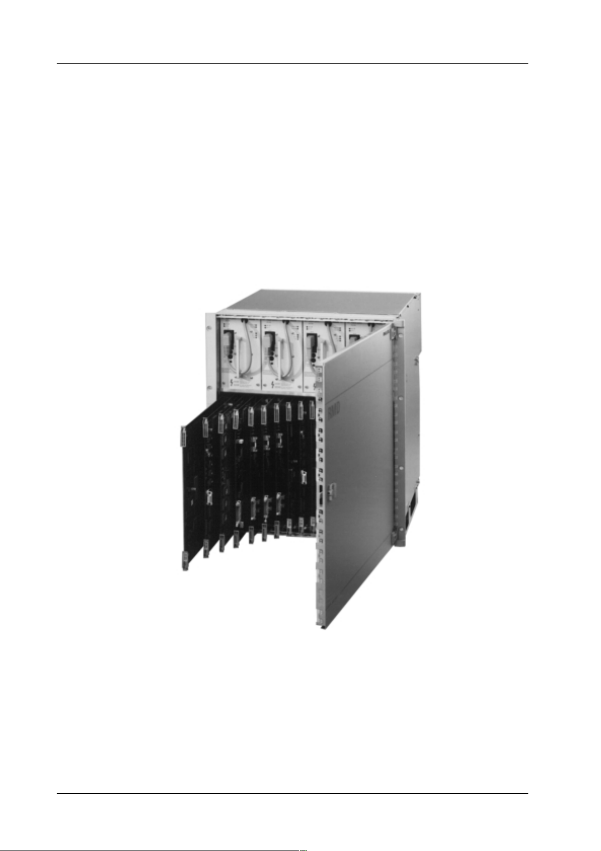
1.1.1 DD 35 BASIC MAINFRAMES – GENERAL FEATURES
Production switcher for serial digital video signals according to ITU–R 601/656
including:
10 Bit Processing / 270 MBit/s
626 / 525 line standard, switchable or auto detect
4:3 / 16:9 switchable, manually or per GPI
19”, 12 RU housing (+ 1HE for air supply),
20 m connection cable (50 ohms, cheapernet)
1 – 2
Operating Instructions – Rev. 16 / 10.2001
Page 17

1. GeneralDD35 Production Switcher
All basic mainframes include:
Power Supply
Switcher Lookahead Preview
Software package: The standard software includes many device drivers ac-
cording to the current state of development.
1–4 Mix / Effect Stages
Keyers and wipe generators see below (Key Functions, Wipe Generators).
32 DSC/SDI inputs each with modifier (Input Correction) for lum., contrast, hue,
color balance.
1 x sync input (analog blackburst)
AUX–Buses see below (Output Processor).
Fade-to-Black stage
Up to 3 more, external DSKs
3 x color backgrounds with 2 mattes each for washes (gradients).
Up to 27 color generators, each with 2 mattes and color wash ramp. Ramp can
be Softened, Rotated and Positioned. For Key Fills, Key Borders,Wipe Borders.
Additional two more color generators in Montage Processor Option (incl. dual
color and wash)
Preview modes: Look Ahead, Chromakey Cursor, Key, Mask, Transition.
10 x RS485 or RS422 serial interfaces
Protocols for edit systems, DVEs, Routers etc., partly optional. (min. 1 RS485
port for extern Tally/GPI needed !)
5 x RS232C serial interface
Modem port RS232C (not yet implemented)
8 internal GPI inputs, 8 internal GPI outputs
Limitation using small mainframe
In conjunction with the small mainframe, the switcher–internal sources COL
BGD 2 and COL BGD 3 are not available.
There is only one wipe generator board which, as in the DD35–4, is used by
both M/Es (WiperFlex). It can be determined by the configuration how to assign
the two generators on the board to the M/Es.
A further restriction concerns the connections to the future FX processor (mon-
tage processor slot). Two of the input and output connections each lead to the
second input processor. It follows from this that with a minimum configuration
(only one input processor with 16 inputs) only two inputs and two outputs of the
FX processor can be used.
Operating Instructions – Rev. 16 / 10.2001
1 – 3
Page 18

1. General DD35 Production Switcher
1.1.2 BASIC MAINFRAME DD 35-4-BM
Basic Mainframe for P/P and 3 M/E
Controller and Software ( for 4 stages)
Input Boards for 32 inputs
Standard Power Supply (2 units)
4 x PGM outputs (DSC) (MAIN OUT)
1 x Main PVW
1 x Clean Feed output, switchable
1 x DP output (diverse operating modes)
3 M/Es with each: 3 x M/E PGM and 1 x M/E PVW outputs
1.1.3 BASIC MAINFRAME DD 35-3-BM
Basic Mainframe for P/P and 2 M/E
Controller and Software for 3 stages
Input Boards for 32 inputs
Standard Power Supply (2 units)
4 x PGM outputs (DSC) (MAIN OUT)
1 x Main PVW
1 x Clean Feed output, switchable
1 x DP output (diverse operating modes)
2 M/Es with each: 3 x M/E PGM and 1 x M/E PVW outputs
1.1.4 BASIC MAINFRAME DD 35-2-BM
Basic Mainframe for P/P and 1 M/E
Controller and Software for 2 stages
Input Boards for 32 inputs
Single Power Supply (1 unit)
1 – 4
4 x PGM outputs(DSC) (MAIN OUT)
1 x Main PVW
1 x Clean Feed output, switchable
1 x DP output (diverse operating modes)
1 M/E with: 3 x M/E PGM and 1 x M/E PVW outputs
Operating Instructions – Rev. 16 / 10.2001
Page 19

1.1.5 BASIC MAINFRAME DD 35–1–BM
Basic Mainframe for 1 M/E
Controller and Software for 1 stage
Input Boards for 32 inputs
Single Power Supply (1 unit)
1 M/E with: 3 x M/E PGM and 1 x M/E PVW outputs
1.1.6 KEY FUNCTIONS (GENERAL)
For each stage (M/E or P/P) one Key Processor (details see below) is manda-
tory. Each type has 3 linear/luminance keyers and 2 borderliners
1 x Key / Mask Store (4:0:0, 8 bit)
for masks/keys/Paint-Mode-Masking
Automated Key Adjustment AKA for all internal Keyers.
1. GeneralDD35 Production Switcher
Key Modifiers: Positioning, Sizing, Softness
2 x borderliners / shadow effects for every keyer
Key masking: box per keyer, wipes or drawing (Paint-Mode-Masking)
1.1.6.1 Key Processor RY 1943 with 2x Chroma Keyers
ChromaKey in Key1 and 2:
Based on a matting technique, DynaChrome achieves an excellent detail and
shadow reproduction, virtually no color spill.
Clip, Gain and FGD-Fade can reduce back ground noise and eliminate most
unwanted shadows. The automatic key alignment (AKA) is pre-adjustable for
any key color. The cursor allows an AKA for every key color.
Manual adjustment is possible, as well as separate adjustment for both adja-
cent hues (selectivities) and a radial displacement away from the center of the
color circle. Selectivity
Masking is the ability that allows different Chromakey settings to be simulta-
neously executed in different image areas within single
1.1.6.2 Key Processor RY 1945 with 1x Chroma Key
ChromaKey in Key1, otherwise like RY 1943. See above.
1.1.6.3 Key Processor RY 1944 without Chroma Key
Key functions see above.
Operating Instructions – Rev. 16 / 10.2001
1 – 5
Page 20

1. General DD35 Production Switcher
1.1.7 OUTPUT PROCESSOR (GENERAL)
One Output Processor (see below) is mandatory
AUX buses (e.g. for DVE Video+Key, Aux-PVW) with auto-follow for various
preview functions.
On Aux buses 1–5, the automatic internal line synchronization can be switched
off in order to allow external device loops (e.g. color correction ...). A feedback
of processed signals into the inputs works without additional 2V synchronization, provided their delay is some micro seconds only.
1.1.7.1 Output Processor RY 2154 with 15 Aux Busses (1–15)
Output Processor with 15 Aux Busses
1.1.7.2 Output Processor RY 2153 with 10 Aux Busses (1–10)
Output Processor with 10 Aux Busses
1.1.7.3 Output Processor RY 2155 with 5 Aux Busses (1–5)
Output Processor with 5 Aux Busses
1.1.7.4 Options for Output Processor
Texture / Matte Store RC 2181
4:0:0 Image store for freezing textures (derived from the wipe generator), respectively key signals for modulating the gradient between the two mattes of
the color background.
The Wash-Key signal can be determined with a wipe generator or from a keyer.
The option does not store the actual colors, but the transition information between them; i.e. with a stored color transition (via wipe), both mattes still can
be changed. Store content lost as soon as mixer is switched off.
Store gets inputs signals from M/E 1.
Image Store (frame grabber) RC 2182
4:2:2 store for freezing one full frame. Frame, Field 1/2 select possible for separate save as well as readout. This allows for 2 separate videos to be stored with
half vertical resolution. Horizontally the store contents can be shifted +/– 128
pixel in + / – 64 steps. ”Grab” function implemented for photo snapshot function-
ality on video.
The input of the store can access all primary sources, as well as the internal
signals PVW, PGM and Clean Feed.
The image store content gets lost as soon as the mixer is switched off.
1 – 6
Operating Instructions – Rev. 16 / 10.2001
Page 21

1.1.8 WIPE GENERATORS (GENERAL)
Per M/E stage one board (see below) can be equipped.
Maximum 3 boards in the mainframe
43 wipe patterns
WiperFlex: Wipe Generator from M/E 1 can alternatively be setup for use in
Program/Preset.
1.1.8.1 Wipe Processor (2x wipe) RY 1908
Board equipped with two generators.
1.1.8.2 Wipe Processor (1x wipe) RY 1909
Board equipped with one generators.
1. GeneralDD35 Production Switcher
Operating Instructions – Rev. 16 / 10.2001
1 – 7
Page 22

1. General DD35 Production Switcher
1.1.9 OTHER MAINFRAME OPTIONS
1.1.9.1 Input Extension Board (Input 33 ... 48) RY 2151
Additional board, provides further 16 (DSC) inputs for expansion to 48 external
sources.
For model DD35–2 this option requires additional power supply RC 2160.
1.1.9.2 Input Extension II (Inputs 49 ... 62) RC 2410
Additional board, provides further 14 (DSC) inputs for expansion to 62 external
sources. Extension to 48 inputs is mandatory for this option. This option cannot
be added later!
1.1.9.3 Montage Processor RY 1913
3 M/E Key Shadows
Movable double frame store for 2 x 4:2:2 or 1 x 4:2:2:4 video.
Manipulations: Additional level adjustment, Invert, Move picture, Posterization,
Solarization, Palette (Hue) Change, Strobe, Grab.
3 x Far Shadow Stores for Drop Shadows on keyed signals (one assignable
per dedicated ME, not in P/P of –4).
For model DD35–2 this option requires additional power supply RC 2160.
1.1.9.4 Redundant Power Supply
Redundant power supply incl. auto switch-over for the DD35 mainframe. Sepa-
rate power supply cords, units exchangeable while in use (hot swap). In case
of failure or switch-over, a warning is given via the Alarm output and/or through
the GUI (TFT–Display).
Redundant Power Supply for DD35-3/-4 Mainframe RC 2180
Redundant Power Supply for DD35-1/-2 Mainframe RC 2160
1 – 8
Operating Instructions – Rev. 16 / 10.2001
Page 23
1.2 CONTROL PANEL MODELS
1.2.1 DD 35 SERIES CONTROL PANELS (GENERAL)
Panel is dark grey.
6 x GP Input, 6 x GP Output
4 x RS485 or RS422 (UMD, Aux ...)
2 x RS232C at panel
Modem port RS232C (not yet implemented)
Built-in PC for new, intuitively usable Graphical User Interface and additional
operational features. Floppy Disk, SCSI HardDisk and TFT Color LCD Display
incl. one software license belong to the delivery extent.
Connectors: 2x RS232C, PC Keyboard, Parallel port, LCD Digital port, VGA
port, separate LAN port.
PS/2 Mouse included.
1. GeneralDD35 Production Switcher
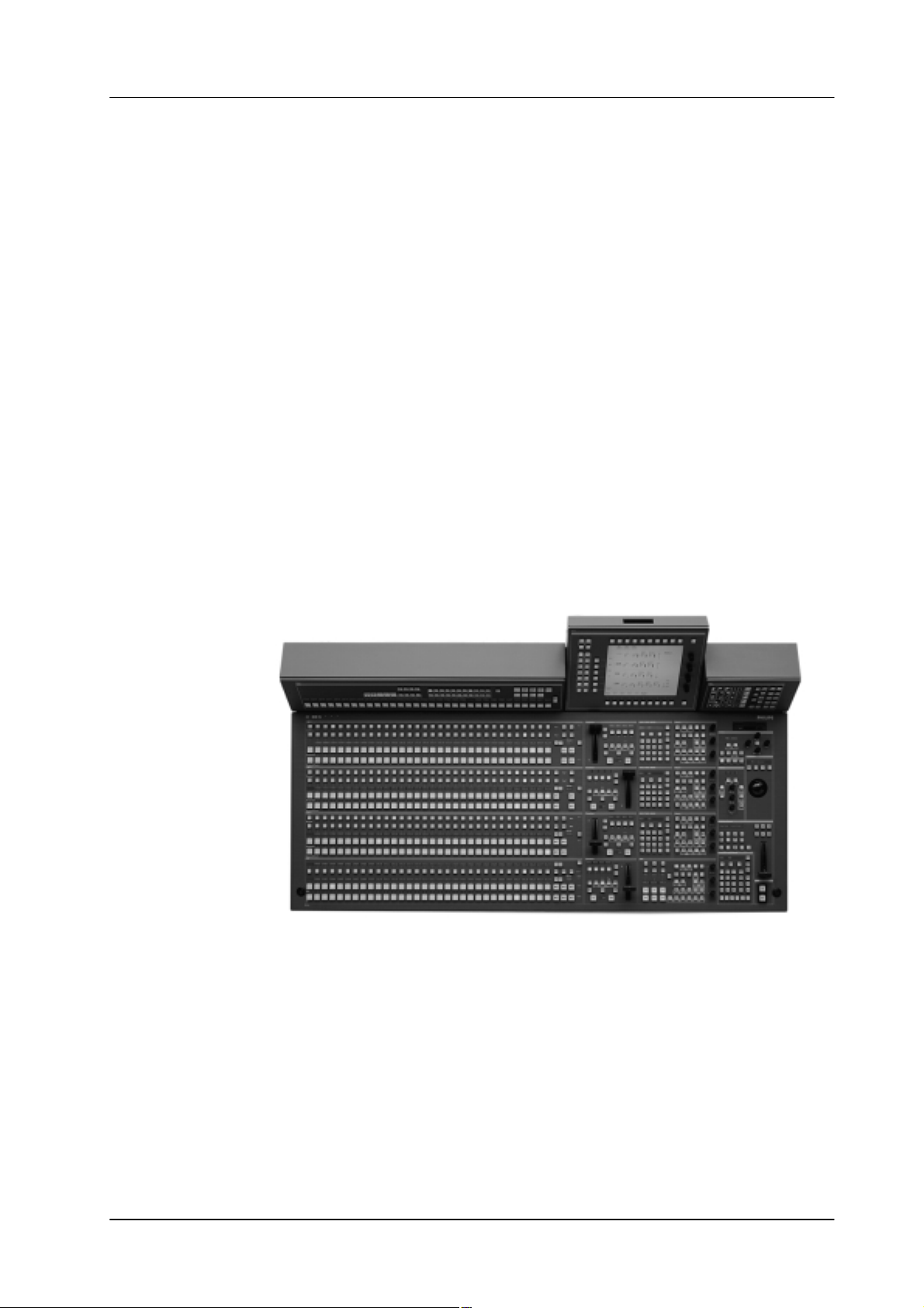
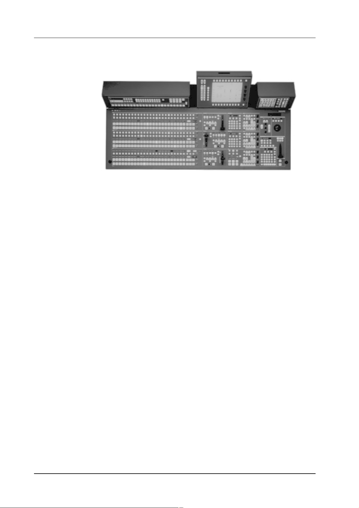
1.2.2 3 M/E PLUS P/P CONTROL PANELS RPS 35-4LX
Control panel set with 32 input source buttons (”LX”)
4 separate modules
Operating Instructions – Rev. 16 / 10.2001
1 – 9
Page 24

1. General DD35 Production Switcher
1.2.2.1 Options (initial order only)
”LX” Input Mnemonics Extension for 3 M/Es RC 2212
4-digit LED Display for the mixer banks. The mnemonics display for the AUX
bus selection and the P/P stage comes as standard.
Redundant Power Supply Panel, RC 2213
Common redundant power supply incl. automatic switch-over for all panel.
Separate power supply cords. In case of failure or switch-over, a warning is
given on panel (DIAGN) and GUI and optional using a GP Output (later orders
possible)
”LX” All-in-one Mounting Frame Set (32 Sources) RC 2227
Is needed when all delivered, separated panel modules have to be combined
for a single unit. This mainly applies to studio desks not having a tilted back wall.
The set contains mounting flanges and facings varnished in dark grey, where
in the long RP A, RPV and RPW modules can be fitted in for attachment to the
RPD35 base panel. A special tilting mechanism is provided for the display module’s viewing angle. Individually adjustable and lockable.
1 – 10
Operating Instructions – Rev. 16 / 10.2001
Page 25
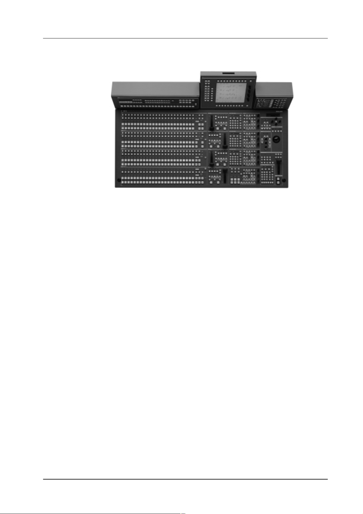
1.2.3 3 M/E PLUS P/P CONTROL PANELS RPS 35-4L
1. GeneralDD35 Production Switcher
Control panel set with 24 input source buttons (”L”)
4 separate modules
1.2.3.1 Options (initial order only)
”L” Input Mnemonics Extension for 3 M/Es RC 2211
4-digit LED Display for the mixer banks. The mnemonics display for the AUX
bus selection and the P/P stage comes as standard.
Redundant Power Supply Panel RC 2213
Common redundant power supply incl. automatic switch-over for all panel.
Separate power supply cords. In case of failure or switch-over, a warning is
given on panel (DIAGN) and GUI and optional using a GP Output (later orders
possible)
”L” All-in–one Mounting Frame Set (24 Sources) RC 2226
Is needed when all delivered, separated panel modules have to be combined
for a single unit. This mainly applies to studio desks not having a tilted back wall.
The set contains mounting flanges and facings varnished in dark grey, where
in the long RP A, RPV and RPW modules can be fitted in for attachment to the
RPD35 base panel. A special tilting mechanism is provided for the display module’s viewing angle. Individually adjustable and lockable.
Operating Instructions – Rev. 16 / 10.2001
1 – 11
Page 26
1. General DD35 Production Switcher
1.2.4 2 M/E PLUS P/P CONTROL PANEL RPS 35-3
Control panel set with 24 input source buttons
4 separate modules
1.2.4.1 Options (initial order only)
Input Mnemonics Extension 2 M/Es RC 2363
4-digit LED Display for the mixer banks. The mnemonics display for the AUX
bus selection and the P/P stage comes as standard.
Redundant Power Supply Panel RC 2376
Common redundant power supply incl. automatic switch-over for all panel.
Separate power supply cords. In case of failure or switch-over, a warning is
given on panel (DIAGN) and GUI and optional using a GP Output (later orders
possible).
All-in-one Mounting Frame Set for RPS 35-3 RC 2360
Is needed when all delivered, separated panel modules have to be combined
for a single unit. This mainly applies to studio desks not having a tilted back wall.
The set contains mounting flanges and facings varnished in dark grey, where
in the long RP A, RPV and RPW modules can be fitted in for attachment to the
RPD35 base panel. A special tilting mechanism is provided for the display module’s viewing angle. Individually adjustable and lockable.
1 – 12
Operating Instructions – Rev. 16 / 10.2001
Page 27

1.2.5 1 M/E PLUS P/P CONTROL PANEL RPS 35–2
Control panel set with 24 input buttons
Aux, Wipe and GUI control section in basic module integrated
1. GeneralDD35 Production Switcher
1.2.5.1 Options (initial order only)
Input Mnemonics Extension M/E+AUX RC 2362
4-digit LED Display for input names
Redundant Power Supply Panel RC 2376
Common redundant power supply incl. automatic switch-over for all panel Sep-
arate power supply cords. In case of failure or switch-over, a warning is given
on panel (DIAGN) and GUI and optional using a GP Output.
Operating Instructions – Rev. 16 / 10.2001
1 – 13
Page 28
1. General DD35 Production Switcher
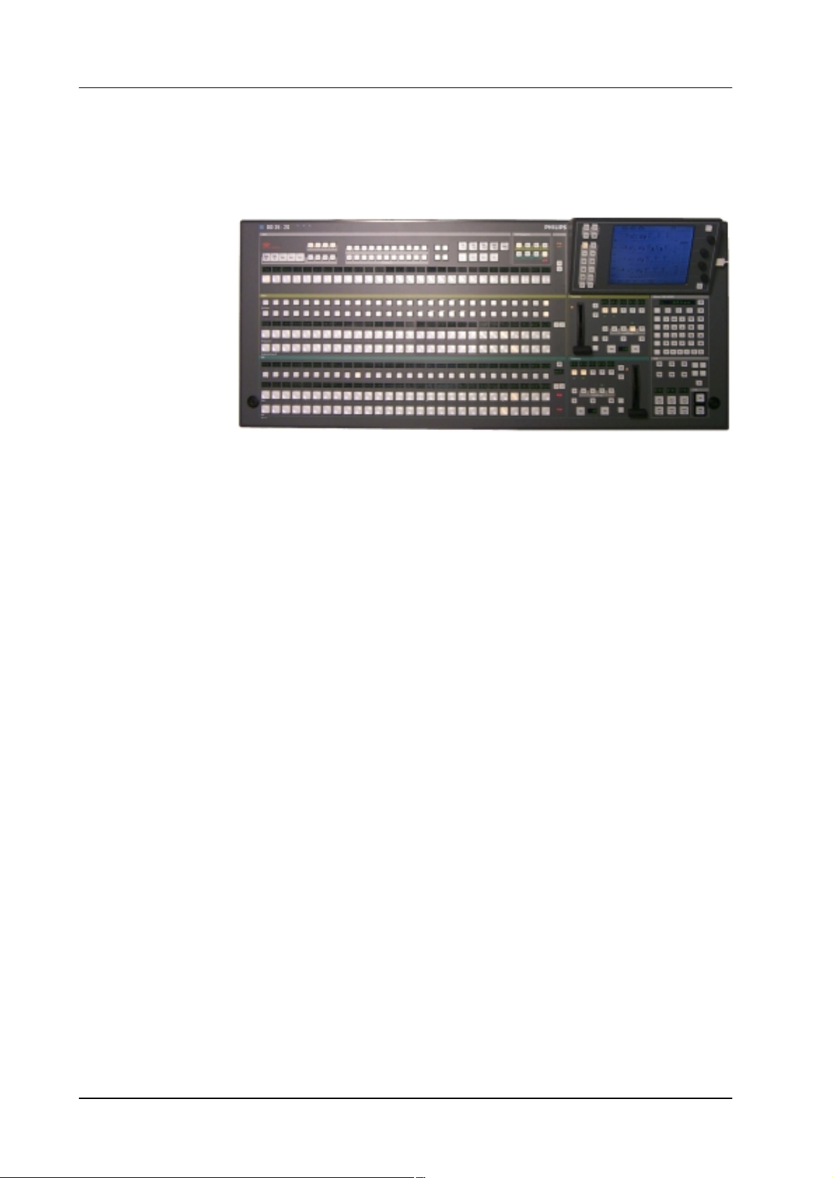
1.2.6 SMALL 1 M/E PLUS P/P CONTROL PANEL RPS 35–2S
The production switcher panel RPD35-2/S with one mixing level M/E and one Program/Preset, as well as the touch screen display panel.
Compact control panel with 28 primary source buttons. Aux and Wipe module integrated. GUI integrated with touch screen. The four USB ports allow connention of
PC peripherals like mouse, floppy drive, CD-ROM etc.
1.2.6.1 Options (initial order only)
Input Mnemonics Extension M/E1 RC 2453–1
Input Mnemonics Extension P/P RC 2453–2
Input Mnemonics Extension AUX RC 2453–3
Input Mnemonics Extension MaKE RC 2453–4
4-digit LED Display row for input names
Redundant Power Supply Panel RC 2376
Common redundant power supply incl. automatic switch-over for all panel Sep-
arate power supply cords. In case of failure or switch-over, a warning is given
on panel (DIAGN) and GUI and optional using a GP Output.
1 – 14
Operating Instructions – Rev. 16 / 10.2001
Page 29

1.2.7 OTHER PANEL OPTIONS (INITIAL ORDER ONLY)
1.2.7.1 Emergency Harddrive, SCSI, min. 2 GB, RC 2148
Must order initially together with basic panel. Operation system software is pre-
configured.
SCSI HDD, min. 2,16 GB, mounted in separate housing for external connec-
tion. With power and SCSI connection cables.
Allows in case of an emergency (head crash etc. ...) the switch-over to external
booting instead of initialization from drive C:.
Note: Automatic update to the working status of the built–in drive C: not sup-
ported at this time.
Operating System Windows 95 pre-installed, as well as side panel SW.
Includes software licenses (Windows 95 & and Sidepanel software DS 0103).
1.2.7.2 Operating System Windows NT for Panel PC, RC 2380
1. GeneralDD35 Production Switcher
in preparation
Operating Instructions – Rev. 16 / 10.2001
1 – 15
Page 30

1. General DD35 Production Switcher
1.3 TALLY OPTIONS
1.3.1 SOFTWARE LICENSE FOR TALLY OPERATION DS 0141
Includes protocols DS0141 and DS0143. This port protocol license entitles the
purchaser to use the Tally option. Tally software translates the internal control
information for further use via serial RS485 ports. Only one license is needed
for control of various distribution units or Facility Control Systems (e.g. Jupiter).
Depending on the number of these units, several Tally channels are available
(known as red, yellow, green Tally) per running Application.
Tally Ch.1: Standard. OnAir source signalling.
Preset Tally: Tally for selected sources not being put OnAir (”yellow”).
Tally Ch. 2: Green Tally like Channel 1, with separate OnAir control input.
Direct connection of tally indicators only via separately available distribution
units (e.g. MI-3040). Source indication assignment dedicated to specific output
pins.
MI-3040 Emulation allows use of MI-3040 units driven by Jupiter Control System. Up to 6 MI-3040 units will then be simulated by using a separate DD35
mainframe port.
1.3.2 TALLY I/O BOX, MI-3040
For switchers with 48 inputs 2 tally boxes are recommended. With 36 inputs 3
tally boxes are recommended.
MI-3040 occupies 2 RU per box. Fastest tally signalling when controlled by
dedicated ports, max. 6 units per RS485 port.
Box1:Red Tally
Box2: Red Tally, Expansion
Box3:IOutputs: Source 49–62
Extra Box: GPI / GPO Expansion, for ext. GPI / GPO a
For Red and Green tally additional boxes are neccesssary.
Outputs: Sources 01–32
Outputs: Sources 33–48, AUX1–15,
Inputs: M/Es, CL, Ready, AUX1–15,
separate software license DS 0140 is
needed.
1 – 16
Operating Instructions – Rev. 16 / 10.2001
Page 31

1.4 SOFTWARE OPTIONS
1.4.1 TIM/E MEMO TIMELINES, DS 0142
Separately shiftable M/E Timelines
in preparation
1.4.2 SOFTWARE LICENSE FOR EXTERNAL GPI/GPO, DS 0140
in preparation
1.4.3 SOFTWARE LICENSE FOR ADDITIONAL SIDEPANEL CONTROL, DS 0103
Separate PC with LAN adapter necessary! Cost effective solution allows DD35
control via external LAN remote connected PC (Ethernet). Many, but not all
main panel functions can be executed from a separate PC workplace (e.g. select of BGD sources not possible).
However, Keyer adjust / control, Mask adjust and adjustment of setups is implemented entirely. This saves the cost for buying a 2nd, smaller Control Panel in
most cases.
Via network all connected units can be controlled from any additional PC. By
loading identical applications, parallel operation of the GUI (Redundancy!)
works as well as exclusive access to DD35 units by loading applications that
have access to unoccupied switcher resources.
1. GeneralDD35 Production Switcher
Operating Instructions – Rev. 16 / 10.2001
1 – 17
Page 32

1. General DD35 Production Switcher
1.5 SHORT DESCRIPTION OF BASIC PROTOCOL DRIVER SOFTWARE
The following software protocol drivers are included in the basic package of the
DD35 switchers:
1.5.1 EDIT PROTOCOL – GVG200, DS 0110
Edit Protocol – GVG / model 200 emulation. Allows DD35 control via edit sys-
tem. Amount of control only in the range of what is possible on a GVG200 switcher (e.g. 20 inputs, 2 M/Es ...), without E-MEMTM Register up/download (switcher learn). E.g. Sony BVE, GVG VPE, etc.
Also often used for remote control of switcher AUX buses for A/B side switch
of foreground and background sources within DVE moves (e.g. DVEous ...).
1.5.2 EDIT PROTOCOL – DD30, DS 0111
Edit Protocol – Philips / DD30 for edit controllers with adapted driver for
DD10/20/30 switchers, e.g. CMX Omni, Accom Axial.
1.5.3 EDIT PROTOCOL – DD35, DS 0132
Edit Protocol: DD35. Allows complete control with proprietary command codes.
Currently (besides Accom Axial with special software) no edit system is known,
controlling DD35 with these commands).
1.5.4 DVE PROTOCOL – DVEOUS, DS 0112
DVE Protocol – Scitex DVEous, A57, A53D. Allows integration of DVE being
controlled from switcher. E.g. good for DVE background transitions and effects
selection via switcher wipe module – as if it were a built in wipe generator.
1.5.5 DVE PROTOCOL – QUESTECH TENX, DS 0113
Amount of control similar to DS 0112.
1.5.6 DVE PROTOCOL – PINNACLE DVEXTREME, DS 0113
Amount of control similar to DS 0112.
1.5.7 DVE PROTOCOL – SONY DME 7000, DS 0115
Amount of control similar to DS 0112.
1 – 18
Operating Instructions – Rev. 16 / 10.2001
Page 33

1.5.8 EXT. DSK PROTOCOL – EASY KEY (OXTEL), DS 0117
Allows integration of Downstream Key command codes for external unit con-
trol. Is extension to internal DSK system. Up to 3 channels (units of same type)
can be controlled with the purchased license. It’s up to the user to setup the
DSK units in cascade or parallel video processing mode and to feed signals
from switcher Aux buses or from an independent, external Routing system.
Supported parameters are: Clip, Gain, Transparency, Cut and Auto.
1.5.9 EXTERNAL DSK PROTOCOL – CDK104 (ROSS), DS 0119
Amount of control similar to DS 0117.
Additional functionality: Box Masking, FTB
1.5.10 EXT. ROUTER PROTOCOL – VENUS, MARS, DS 0120
Enables remote control of input source selection of up to 15 outputs from an
external Philips router (ASCII protocol).
1. GeneralDD35 Production Switcher
1.5.11 EXTERNAL ROUTER PROTOCOL – SANDAR, DS 0121
Enables remote control of input source selection of up to 15 outputs from an
external Sandar router. Includes Mnemonic Transfer.
1.5.12 NAME FOLLOW VIDEOTM – VENUS, DS 0123
Is needed for transfer of mnemonics names from extern router (or integrated
control system, e.g. Jupiter ...) into the switcher mnemonics (M/Es, Aux, P/P).
1.5.13 UNDER MONITOR DISPLAY PROTOCOL – PHILIPS, DS 0126
Enables transmission of DD35’s mnemonics names into Philips Under Monitor
Displays of type RP1, RP2 and RP3 UMD. Names assigned in switcher can be
4 and 8 characters long (new !). Up to 8 digits supported.
1.5.14 AUX PANEL – PHILIPS CP-300/330/3020/321, DS 0129
Allows for remote control of switcher Aux buses by separated keyboard units
(buttons) of type CP300.. etc. Uses MPK protocol. Assignment of remote keyboard buttons can be altered with changing configuration setups per application.
Aux buses individually programmable.
1.5.15 AUX–BUS PROTOCOL, DS 0133
For AUX Bus control e.g. from DVEs
Operating Instructions – Rev. 16 / 10.2001
1 – 19
Page 34

1. General DD35 Production Switcher
1.5.16 MACHINE CONTROL – BVW75 (SONY), DS 0144
Allows remote control of tape machines, disk recorders etc., which listen to this
protocol. Supported are all tape motion commands: Stop, Play, VarPlay,
Shuttle, Jog, Cue, Rewind, FFWD. Recorded as Crash Record.
1 – 20
Operating Instructions – Rev. 16 / 10.2001
Page 35

2. PANEL OPERATION
2.1 OVERVIEW
2. Panel OperationDD35 Production Switcher
Aux panel
Wipe panel
Disk drive
Positioner
Masks panel
Mattes panel
GUI menu panel
1
1
Source selection panels
M/E1
M/E2
M/E3
P/P
Example RPS35–4L Control Panel
Transition panels
M/E1
M/E2
M/E3
P/P
Operating Instructions – Rev. 16 / 10.2001
TiM/E Memo
M/E1
M/E2
M/E3
Master
Key control
M/E1
M/E2
M/E3
P/P
Machine control
1
1
Fade-to-Black
2 – 1
Page 36

2. Panel Operation DD35 Production Switcher
2.2 SOURCE SELECTION
The DD35 Series Production Switcher are equipped with 32 (standard), 48 or 62
serial digital inputs, each usable as a video or key signal. The following internal signals are also available:
Black, White
3 color backgrounds (Col1, Col2, Col3)
Video store (optional)
Montage processor (optional)
Re-entry from M/E1, M/E2, M/E3
Re-entry of Program/Preset and “Clean Feed”
16 “virtual” inputs with key memory (any normal input with secondary input cor-
rection)
Layer mode: the combined key signals of M/E1, M/E2 or M/E3.
Note: M/Ex cannot be selected as a picture source
Re-entry problem
Solution
When selecting the source, it may happen that the switcher levels M/E1, M/E2,
M/E3 or P/P cannot be re-entered as a source in another switcher level. This is not
a fault, but a protective mechanism to avoid loops and consequently timing problems. In this case, the switcher system prevents that close loops are built when selecting the busses. For instance, in level M/E3, M/E1 cannot be selected when in
one of the most different combination paths the source M/E3 has been already selected in level M/E1.
Find and disconnect the connention which prevent the picture source from being
re-entered. Beside the direct selection via the source buttons, there is a number
of internal connections which are not recognizable at the first sight.
Selection of the mask bus can be looked up in the Mask menu and all the other ones
(PGM, PST, Key, Fill) in the Status menu.
2 – 2
Operating Instructions – Rev. 16 / 10.2001
Page 37

2. Panel OperationDD35 Production Switcher
Control panels
Two types of panels are available for the DD35-4 switcher: The smaller
“RPS35–4L” panel with 24 primary source buttons and the “RPS35–4LX” panel
with 32 primary source buttons.
Any input can be assigned to any button. Most internal inputs can also be assigned
to any button. Key and Fill signals may be coupled in any combination.
Example: RPD 35-4LX control panel
ME1
Key Buses
Background A
Background Preset B
ME2
Key Buses
Background A
Background Preset B
ME3
Key Buses
Background A
Background Preset B
PP
PGM
PST
ME2
Key 1
ME2
Key 2
2nd
ME 2 ME 3
ME 2 ME 3
ME1
ME1
Key 2
2nd
ME 1
ME 1
ME1
ME2
ME1
ME2
2nd
ME 1
ME 2
ME 1
ME 2
2nd
ME2 ME3ME1
2nd
ME 1 ME 2 ME 3
ME 1 ME 2 ME 3
On air
ME3
Uncal
On air
ME3
Uncal
TiME
On air
Uncal
On air
Uncal
On air
ME3Key 1
Uncal
On air
ME3
Uncal
TiME
On air
ME 3
Uncal
On air
ME 3
Uncal
On air
Key 1
Uncal
On air
Key 2
Uncal
TiME
On air
Uncal
On air
Uncal
MaKE
On air
Uncal
On air
Uncal
Operating Instructions – Rev. 16 / 10.2001
Program and Preset buses, DSK, MaKE
Key1, Key2, Background A, Background Preset B buses M/E3
Key1, Key2, Background A, Background Preset B buses M/E2
Key1, Key2, Background A, Background Preset B buses M/E1
2 – 3
Page 38

2. Panel Operation DD35 Production Switcher
Example: RPD 35-3 control panel
M/E1
Key Buses
Background A
Background Preset B
M/E2
Key Buses
Background A
Background Preset B
P/P
PGM
PST
TiM/E MEMO
ME2 ME3ME1
ME2 ME3ME1
2nd 3rd
ME 1 ME 2 ME 3
ME 1 ME 2 ME 3
TiM/E MEMO
ME2 ME3ME1
ME2 ME3ME1
2nd 3rd
M/E2
ME 1 ME 2 ME 3
ME 1 ME 2 ME 3
2nd 3rd
ME2 ME3ME1
2nd
3rd
ME 1 ME 2 ME 3
ME 1 ME 2 ME 3
M/E1
DELREC INS-P
P/P
Selected
Selected
Selected
Selected
Selected
Selected
Selected
Selected
MaKE
Selected
Selected
On air
Uncal
On air
Uncal
TiM/E
Memo
On air
Uncal
On air
Uncal
On air
Uncal
On air
Uncal
TiM/E
Memo
On air
Uncal
On air
Uncal
On air
Uncal
On air
Uncal
On air
Uncal
Program and Preset buses, DSK, MaKE
Key1, Key2, Background A, Background Preset B buses M/E3
Key1, Key2, Background A, Background Preset B buses M/E1
2 – 4
Operating Instructions – Rev. 16 / 10.2001
Page 39

2. Panel OperationDD35 Production Switcher
2.2.1 FUNCTION OF THE BUSES
Background A The Background A bus indicates which background picture is currently selected.
Pressing another button in this bus performs a hard cut to another background picture. The selected background picture can be viewed on the corresponding M/E
program monitor.
Background Preset B The Background Preset B bus serves to select the background picture involved
in the next transition. The preset background picture and the selected modifications
(keys, for example) can be viewed on the corresponding M/E preview monitor.
The background and preset buses operate in “Flip-Flop” mode. After completion
of the background transition, the preset source is automatically selected on the
background bus and the original background source is automatically “flipped” to the
preset bus.
The background and preset bus can be changed from the “international mode”
(preset bus below) to “preset upper” mode (background bus below). For further information please refer to the Installation menu.
Key1 / Key2 Buses The Key Buses are for the selection and indication of key and fill signals.
Cut
BGD
B
BGD
A
Key
Layer
Key
1
2
For details on key source control please refer to the sections Keyer Panels and
Transition Panel.
2nd Delegation The 2nd button allows for the selection of further sources (up to 48) in addition to
the 24 (32) directly selectable sources. The 2nd button will light when pressed. The
current button assignment can be read from the respective button display.
If the optional Input Mnemonics is not installed, source identification on adhesive
foil is suggested.
3rd Delegation The 3rd button allows for the selection of further sources (up to 62) in addition to
the 24 (32) directly selectable sources. The 3rd button will light when pressed. The
current button assignment can be read from the respective button display.
If the optional Input Mnemonics is not installed, source identification on adhesive
foil is suggested.
On Air Buses involved in the output picture are indicated with a red On Air to the right o f
the bus.
Operating Instructions – Rev. 16 / 10.2001
2 – 5
Page 40

2. Panel Operation DD35 Production Switcher
Asynchronous Sources
Asynchronous (non-synchronous) sources are indicated by either a red or greenflashing On Air depending on the on air status.
Note: Asynchronous picture signals are instantaneously switched through
by the switcher. An interference-free operation of the downstream
keyers is not always guaranteed.
Uncal
MaKE/Aux
(only in P/P)
The yellow Uncal indicator lights when a change from the default settings on the
switcher has been made, such as, one or more of the following:
the bus correction is non-default
the selected source has a non-default input correction
opacity is non-default
P/S/S is on (Positioning, Sizing and Softening parameters are stored in the key
memory)
Button delegates the Key bus buttons of the P/P panel to the following functions:
Example: Part of the RPD 35-4 panel
MaKE
Aux
MaKE
...
Macro or Aux Selection
2nd
ME2 ME3ME1
Rec Ins-P Del
2 – 6
For special applications the Aux bus input button row can be moved from the
Aux Panel to the P/P panel.
Make Memo function for storing and recalling macros. Operation with the
panel buttons see below. For operation with menu refer to section Config
Panel menu.
Operating Instructions – Rev. 16 / 10.2001
Page 41

2.2.2 MAKE MEMO OPERATION
2.2.2.1 MACRO GENERATION WITH THE PANEL BUTTONS
MaKE Memo is a new feature. It can store commands as macros (e.g. Cut, Auto,
GPO trigger, etc.). By inserting Pause between commands it can also store a
macro sequence. The difference between TiM/E Memo with snapshots and timelines to MaKE Memo is, that TiM/E Memo stores states and sequences of states,
MaKE Memo stores commands and sequences of commands.
For recalling the stored macros, the P/P source selection panel is used. The MaKE
button delegates the P/P keyer bus to the MaKE Memo function.
Example: Part of the RPD 35-4 panel
2. Panel OperationDD35 Production Switcher
2nd
...
Macro or Aux Selection
Record a macro
Rec Ins-P Del
Press MaKE button.
Press ME1/Rec button and hold it down.
Select the macro button on the key bus row of the P/P stage. The selected key
bus button is now blinking (record mode). If a macro was already stored in this
position, it will be overwritten.
Press the selected button on the key bus again to stop and store the recording.
Insert Pause During macro recording, pauses can be inserted:
Press ME2/Ins-P button and hold it down. The key bus row is switched into the
”Pause Mode”, i.e. the display of the individual buttons offer different times for
selection (e.g. 1.3s for 1.3 seconds).
Pressing a button adds the corresponding time as a pause to the recorded
macro. By selecting the button 2nd or 3rd, the “Pause Mode” offers still a larger
number of time values for selection. When selecting several time values in succession without pressing another button in between, the sum of the corresponding times will be added as a pause.
MaKE
Aux
ME2 ME3ME1
MaKE
Operating Instructions – Rev. 16 / 10.2001
2 – 7
Page 42

2. Panel Operation DD35 Production Switcher
Play a Macro To play a macro or a sequence
Press MaKE button.
Select the macro button on the key bus row of the P/P stage. While the macro
is executed, the button is lit. Pressing the button while the macro is still running
stops the macro. After stopping/terminating, the button (i.e. the l a mp in the button)goes out again.
While the macro is running, no other macro can be started, recorded or deleted.
Delete a Macro To delete a macro or a sequence
Press ME2/Del button and hold it down and select the macro with the buttons
of the key bus row.
Joining Macros
Pressing another macro button during a macro recording, the macro associ-
ated to this button is not started but its data is added to the recorded macro.
Note:
Button lamp of current macro blinking in single speed while playing. Lamp of cur-
rent macro and delegation lamp blinking in double speed while recording.
Lamp of last played keeps lit. If the last played macro is deleted, the lamp will be
switched off. After a reset, the last played macro is undefined and so no lamp is on
to indicate the “last” state.
2 – 8
Operating Instructions – Rev. 16 / 10.2001
Page 43

2.2.2.2 MACRO ATTACHMENT
Under several circumstances it is useful to execute a macro together with the function of another button. E.g. when selecting a VTR which is under –> Machine Con-
trol on the Preset Bus it could be useful to cue the machine to the Mark In point.
Or think about selecting a store (Video Store, Montage Processor) output and select the readout with the same button push.
For such uses the Macro Attachment is the tool to use. With macro attachment the
macro can be added to the normal button function. In this case a macro can be executed before the normal function (pre–macro); it can be executed after the normal
function (post–macro) or both pre–macro and a post–macro can be activated.
A macro can also replace the normal function of the button.
This is selected by Macro attachment Playmode for all the macro attachments
made.
Function only means that regardless whether a macro has been attached or
not only the normal function is executed.
Function and macros means that if there is a macro attached the normal func-
tion and the macro(s) is (are) is executed.
2. Panel OperationDD35 Production Switcher
Macros only means that if there is a macro attached, only the macro is exe-
cuted.
The macro attachment is done in the following easy steps:
Record the macro(s)
Pre–macro:
Press and hold the button where the macro is recorded to.
Press and hold the button where the macro should be attached to.
A beep after 2 seconds indicates that the attachment is stored. Both buttons
can then be released.
Post–macro:
Press and hold the button where the macro should be attached to.
Press and hold the button where the macro is recorded to.
A beep after 2 seconds indicates that the attachment is stored. Both buttons
can then be released.
Pre–macro and post–macro:
First attach the pre–macro.
Then proceed to attach the post–macro.
Note!
during the process of attaching the macro the macro and the button’s function will be executed.
To delete the macro attachment:
Activate the MaKE–Memo row
Press and hold M/E3 / Del button
Press the button from which the macro attachment should be deleted from.
A beep will indicate the delete has occoured.
All macro attachments can be deleted in the panel setup.
Operating Instructions – Rev. 16 / 10.2001
2 – 9
Page 44

2. Panel Operation DD35 Production Switcher
2.2.3 AUX BUS ASSIGNMENT IN P/P PANEL
For special applications it is possible to delegate the Aux bus selection from the Aux
bus panel to the key bus row of the P/P panel. This button row can alternatively be
used for the MaKE memo selection.
To move an Aux bus:
Press the MaKE/Aux delegation button and hold it down. The display beside
the button shows AUX?.
Then press the delegation button in the respective Aux panel section (e.g.
AUX3 or MontProc1) and release the MaKE/Aux delegation button.
Aux1 Aux2
Aux8 Aux9
Aux3 Aux4 Aux5 Aux6 Aux7
Aux10 Aux11 Aux12 Aux13 Aux14 Aux15
Delegation
Mont
Proc1
Mask
Bus1
Mont
Proc2
Mask
Bus2
Video
Store
Mask
Bus3
Ext
Aux
Instead to delegate to the MaKE memos, the MaKE delegation button now
toggles between the key bus row (DSKs) and the selected Aux bus.
In this mode, the MaKE memos can be only used in the menu.
If you want to delegate the MaKE memos again to the button row, proceed as follows:
Press the MaKE/Aux delegation button and hold it down. The display beside
the button shows AUX?.
Then press one of the buttons ME1/Rec, ME2/Ins-P or ME3/Del in the P/P
panel and release the MaKE/Aux delegation button.
The Aux bus assignment can be also controlled from the Config Panel menu where
the first list entry ALL has to be selected in the MaKE Memo list. Subsequently, a
menu is displayed for bus selection.
2 – 10
Operating Instructions – Rev. 16 / 10.2001
Page 45

2.3 AUX BUSES PANEL
2.3.1 OVERVIEW
The Aux Buses panel is used to select and indicate the sources on:
up to 15 internal Aux Buses (Seraph HD up to 20 Aux Buses)
up to 15 external Aux Buses
Video Store (if equipped)
Montage Processor (if equipped)
Mask Bus in M/E1 ... 3 (if available. Not available in Layer and P/P mode.)
For example the DD35 provide in the basic version 5 serial digital auxiliary outputs.
The “Aux Extension options” provides an additional 5 or 10 outputs for a maximum
of 15 Aux Buses.
Any Aux bus can be used as Aux PVW. Any Aux bus can also be used to feed a
DVE with video or key (see menu Install / EBox / DVE).
2. Panel OperationDD35 Production Switcher
AUX
On Air
PGM
Preset
B
CAM1 CAM2 CAM3 CAM4 VTR1 VTR2 VTR3 VTR4 CHG1 CHG2 STIL SIL EXT1 EXT2 EXT3
Key2
A
Key3Key1
Example: RPD 35-4 control panel
AUX
On Air
PGM
Preset
B
CAM1 CAM2 STIL SIL EXT1 EXT2 EXT3
Key2
A
Key3Key1
Aux
Enbl
ME1 ME2
VTR
Enbl
Remote
Edit
Enbl
ME3 PP
GPI
Enbl
EXT4 DVE2 CINE SDR1 SDR2 PROC NR COL1 COL2 MATTDVE1
Aux4 Aux5 Aux6 Aux7
Aux2
Aux3
Aux1
Aux11 Aux12 Aux13 Aux14
Aux9
Aux10
Aux8
Bus Delegation
Example: RPD 35-3 control panel
Aux
Enbl
ME1 ME2
VTR
Enbl
Remote
Edit
Enbl
ME3 PP
Aux15
GPI
Enbl
EXT4 DVE2 CINE SDR1 SDR2 PROC NR COL1 COL2 MATTDVE1
Mont
Mont
Proc2
Proc1
Mask
Mask
Bus2
Bus1
Aux1 Aux2
Aux8
Video
Store
Mask
Bus3
Aux9
Ext
Aux
2nd
Aux
Aux3 Aux4 Aux5 Aux6 Aux7
Aux11 Aux12 Aux13 Aux14
Aux10
Bus Delegation
PVW PVWPVW
ME1
ME1 ME3ME2
NR COL1 COL2 MATT
BLCK
ME2
Menu
ME3
Aux15
PVW
M/E3 P/P
M/E3 P/P
M/E3 P/P
PVW
Clean
P/P
ME3ME2
P/P
3rd
2nd
BLCK
On air
Uncal
PVW PVWPVW
Ext
Aux
2nd
Aux
Menu
BLCK
M/E Delegation
ME1
ME1 ME3ME2
NR COL1 COL2 MATT
M/E1 M/E2
M/E1 M/E2
M/E1 M/E2
On air On airOn airOn air
Mont
Video
Mont
Proc2
Store
Proc1
Mask
Mask
Mask
Bus2
Bus3
Bus1
Clean
P/P
P/P
3rd
2nd
BLCK
On air
Uncal
Operating Instructions – Rev. 16 / 10.2001
2 – 11
Page 46

2. Functional Description DD35 Production Switcher
2.3.2 AUX BUS SOURCES
The Aux Buses bank permits the selection of the same signals as on Background
and Key buses. Additionally
PVW signals of all stages (M/E1 ... 3, P/P)
P/P output
Pre-processed Background Bus, Key Bus and Fill Bus signals (Preset/B,
PGM/A, Key1, Key2, Key3 in P/P only) of any stage.
2.3.3 AUX BUS DELEGATION
The button group Delegation delegates one of the buses to the Aux Bus buttons
row. Thus showing the respective status and enabling operation.
Aux1
Aux8
Aux2
Aux9
Aux4 Aux5 Aux6 Aux7
Aux3
Aux11 Aux12 Aux13 Aux14
Aux10
Delegation
Aux15
Mont
Proc1
Mask
Bus1
Mont
Proc2
Mask
Bus2
Video
Store
Mask
Bus3
Ext
Aux
2nd
Aux
Menu
The other statuses are stored internally and are automatically stored when another
Aux bus is selected.
Program, Preset and Key buses and the Aux buses can be coupled in any combination (for further details please refer to section Config menu).
Note:
Holding an input button pressed and then pressing one or more aux delegation but-
tons (Aux1, Aux2, ..., Mask Bus3) will set this input active for the delegated aux
buses. While the input button is pressed down no source hunting will be achtive.
This means, you can set all aux buses to the same input (e.g. Black). Press Black,
hold the button down, and than strike with your finger over all aux delegation buttons.
2 – 12
Operating Instructions – Rev. 16 / 10.2001
Page 47

2. Panel OperationDD35 Production Switcher
Special buttons:
2nd Aux The 2nd Aux button allows for the selection of further sources.
The 2nd button will light when pressed. The current button
assignment can be read from the respective button display.
Seraph HD: Sources Aux 16 ..20
DD35: Sources DVx 1/2, DVx 3/4
Menu Selecting the Menu button and simultaneously pressing one of the
buttons Wipe 1 ... 4, VideoStore or MPR1/2 calls on the Aux but-
ton row a simplified version of the associated menu buttons. The
function names of the buttons are shown in a short form in the
4–digit display. This operating mode can be useful when the control panel is operated without display or defined operational functions have to be available via direct button access.
Analog settings are possible by pressing the % buttons and simultaneously rotating the digipots in the Matte panel.
As soon as pressing another delegation button in the Aux panel,
this operating mode is exit and the Aux button row is assigned to
the corresponding sources.
Note:
If you have a panel without Menu button, for this mode of operation
please press simultaneously the buttons Matte + Matte +
Matte1 + (Wipe 1 ... 4, VideoStore or MPR1/2).
Operating Instructions – Rev. 16 / 10.2001
2 – 13
Page 48

2. Functional Description DD35 Production Switcher
2.3.4 ENABLE THE REMOTE FUNCTIONS
Edit
Aux
Enbl
VTR
Enbl
Enbl
GPI
Enbl
Remote
The Remote button groub has to be used to enable the following functions:
Enables Aux control panels
Enables the VTR control
Enables editor control
Enables GPI inputs
2.3.5 CENTRAL ON–AIR DISPLAY
AUX
On Air
display
On Air
PGM
Preset
B
CAM1 CAM2 STIL SIL EXT1 EXT2 EXT3
Key2
A
General red signalling of the switcher output. Buses involved in the output picture
are indicated with a red On Air to the right of the involved buses.
Edit
VTR
Enbl
Remote
GPI
Enbl
Enbl
Aux1
ME3 PP
Aux8
EXT4
DVE1 BLCK
Aux4 Aux5 Aux6 Aux7
Aux2
Aux3
Aux11 Aux12 Aux13 Aux14
Aux9
Aux10
Bus Delegation
DVE2 CINE SDR1 SDR2 PROC NR COL1 COL2 MATT
Aux15
Mont
Proc1
Mask
Bus1
PVW
PVW
ME3ME2
ME3ME2
PVW
Clean
P/P
P/P
3rd
2nd
BLCK
On air
Uncal
PVW
ME1
Ext
Mont
Video
Menu
Aux
Proc2
Store
2nd
Mask
Mask
Bus2
Bus3
Aux
ME1
NR COL1 COL2 MATT
Aux
Enbl
ME1 ME2
Key3Key1
2 – 14
Operating Instructions – Rev. 16 / 10.2001
Page 49

2.4 SOURCE SELECTION GROUP
For operator convenience, the source selection rows can be swapped in the Environment Setup. See also: Menu Install / Panel / Preset Is Upper (formerly PGM/
PST German).
2.4.1 BACKGROUND A
The Background A bus source is selected and indicated on the Background A
bus bank. Pressing another button in this bank performs a hard cut to the new
source.
In Non-Layer mode, the Background A bus is the Program bus.
In addition to the source selection, the switcher performs the actions shown in the
table when the appropriate Application Setting is turned on (for details see menu
Config / EBox / ME Settings).
2. Panel OperationDD35 Production Switcher
Application Setting Action
Button Drop (!= None) The selected buttons will be dropped i.e. cut out when a pro-
Black Pst Abort A currently running transition with BLK Pst on will be aborted,
Transition Abort A currently running transition will be aborted and the selected
FTB Cancel When Fade-To-Black is active, this will be instantly cancelled,
gram source is selected. Mainly used for DSKs.
the BLK Pst button lamp turns off and the selected source is
taken fully as program.
source is taken fully as program.
so that the image with the selected source is visible on the
stage’s program output.
In Layer mode, the Background A bus is the bus of the key BGD-A – similar to
the standard key buses Key 1 and Key 2. I.e. the key selection mode of the Keyers
Panel (Key Bus, Couple, Split) applies.
Operating Instructions – Rev. 16 / 10.2001
2 – 15
Page 50

2. Panel Operation DD35 Production Switcher
The following table shows what happens under the various conditions.
Key
Selection
Mode
Indication Operation
identical Key Bus but-
ton is lit
coupled Couple/Split
button is lit
split Couple/Split
button + Split
indicator lit
split Couple/Split
button + Split
indicator lit
Couple/Split
not pressed
Couple/Split
pressed
select Fill and Key source together and identical
select Fill source and the Coupled Key input as
Key source (the Coupled Key input is defined in
menu Application / Global Settings / Input)
select Fill source
select Key source
Refer to Keyers Panel how to switch the key selection mode.
In addition to the source selection, the switcher performs the actions shown in the
table when the appropriate setting is turned on.
Application Setting Action
Black Pst Abort If a currently running transition with BLK Pst on is at the black
limit, it will be aborted, the BLK Pst button lamp turns off, the
switcher changes to non-layer mode and the selected source
is taken fully as program.
2 – 16
Operating Instructions – Rev. 16 / 10.2001
Page 51

2.4.2 BACKGROUND B
The Background B bus source is selected and indicated on the Background Pre-
set B bus bank. Pressing another button in this bank selects a new source. No addi-
tional action is performed.
In Non-Layer mode, the Background B bus is the Preset bus. The background
image for the next BGD transition is selected on it. Usually this can be previewed
on the stage’s preview output.
Program and Preset bus operate in Flip-Flop mode, i.e. after the BGD transition,
the preset and program sources will change automatically.
In Layer mode, the Background B bus is the bus of the key BGD-B – similar to
the standard key buses Key 1 and Key 2. I.e. the key selection mode of the Keyers
Panel (Key Bus, Couple, Split) applies.
2.4.3 PRE-PROCESSED SIGNAL SELECTION GROUP
2. Panel OperationDD35 Production Switcher
Each M/E stage of the switcher has the capability to send one processed key signal
and one processed video signal to the internal router. The signals can be taken
from any background or key.
For example: Key 1 is in chroma key mode DynaChrome. Then the processed ke y
output is the black-and-white key signal, the processed video signal is the foreground signal with key color subtracted.
Button group in the Aux panel section:
Preset
Button Preset B PGM A Key1 Key2
associated Video Bus B Bus A Fill of Key1 Fill of Key2 Fill of Key3
associated Key
– non-layer mode:
– layer mode:
full image white
Key of BGD B
PGM
B
full image white
Key of BGD A
A
Key2
Key of Key1 Key of Key2 Key of Key3
Key3Key1
M/E1 M/E2
M/E3 P/P
1
Key3
1
Only in stages with three keyers.
Operating Instructions – Rev. 16 / 10.2001
2 – 17
Page 52

2. Panel Operation DD35 Production Switcher
The pre-processed signals can be selected on
logical DVE buses (see also section: DVE Integration)
any AUX bus (it is an application setup whether the AUX bus takes the pro-
cessed video or the processed key)
Montage Processor
(MPR1 always uses the video and MPR2 always uses the key)
VideoStore (always the video)
The pre-processed signals cannot be selected on the Mask buses and on the external AUX buses.To select a specific signal:
Press and hold down the respective M/E button
Press the button of the signal to select
Release the M/E button
Since each stage can send only one out of the four or five possible signals, there
might be a conflict. For example:
AUX1 has selected Key1 of M/E 1.
When a selection for AUX2 is made to send Key2 of M/E 1, there is a conflict,
because only either Key1 or Key2 can be sent.
To resolve this conflict, the DD35 switcher uses the principle ”the last one wins”.
In this case, Key2 of M/E 1 is then selected on both buses AUX1 and AUX2.
2 – 18
Operating Instructions – Rev. 16 / 10.2001
Page 53

2. Panel OperationDD35 Production Switcher
2.5 M/E DELEGATION (ONLY IN RPD 35-2 AND RPD 35-3 PANELS)
Each M/E stage of the switcher can be delegated to each control level of the control
panels. Refer also the menu section ME-Mapping and Local Panel Setup.
M/E Delegation
Example: RPD 35-3 control panel
M/E1 M/E2
M/E1 M/E2
M/E1 M/E2
On air On airOn airOn air
M/E3 P/P
M/E3 P/P
M/E3 P/P
Operating Instructions – Rev. 16 / 10.2001
2 – 19
Page 54

2. Panel Operation DD35 Production Switcher
2 – 20
Operating Instructions – Rev. 16 / 10.2001
Page 55

2.6 TRANSITION PANEL
The DD35 Production Switchers include a universal mixing level with a background
transition stage and two independent keyers.
With both keyers, Luminance and Linear Key mode can be enabled. The DynaCh-
rome keyer is an option per M/E including P/P.
The transition panels for the M/E1, M/E2 and M/E3 levels are set up identically. For
an ergonomic layout, the fader for the M/E2 and P/P level are arranged on the righthand side of the panel.
Example 1: RPD 35-4 Transition panel
Transition
2. Panel OperationDD35 Production Switcher
WP 1
Limit
set
Limit
on
Loop DVE Mix
BLK
Pst
BGD BGD Key
BA
BB
On On On On
Fx
Layer Over Over
Auto
WP 2 MIX WP 2
1
Fx Fx
Wipe
1
Transition types
Trans
dur
1 2 3 4
Key
Wipe
Trans
PVW
Cut
2
Fx
2
Operating Instructions – Rev. 16 / 10.2001
2 – 21
Page 56

2. Panel Operation DD35 Production Switcher
In compare to the RPD 35-4 control panel, the RPD 35-2 and RPD 35-3 panel have
more buttons and gives therefore the possibility to select the 3rd keyer without
changing UPK button functions. Additionally a fader status bar supports the fader
operation.
Example 2: RPD 35-2 and RPD 35-3 Transition panel
Transition
Limit
set
Limit
on
WP 1 WP 2 MIX WP 2
BGD BGD Key
BA
BB
On On On On
Fx
Loop DVE Mix
BLK
Pst
Fx Fx
Layer Over Over
Auto
MIX
Key
1
On
Fx
Over
Wipe
Transition types
Trans
dur
1 2 3 4
2
1
Key
3
Fx
Wipe
2
Trans
PVW
Cut
For effect design, ADD, Mix, DVE, Wipe1 and Wipe2 transitions can be selected
with up to two wipe generators (optional). The individual picture components can
be simultaneously faded with different transition types (MultiMix).
Control of the mixing level is facilitated by the consistent application of the nexttransition principle.
2 – 22
For an optimum preview of the transition effect, the switcher is equipped with independent preview mixing levels and Transition PVW capabilities.
Note: Please note that the transition type ADD has to be set in the M/E Main
menu.
Operating Instructions – Rev. 16 / 10.2001
Page 57

2. Panel OperationDD35 Production Switcher
2.6.1 TRANSITION FUNCTIONS
Next Transition The next-transition buttons BGD B, BGD A, Key 1, Key 2 and Key 3 permit the
preselection of the picture components to be involved in the next transition. The
buttons are mutually exclusive. If you wish to fade several picture components
simultaneously, press the respective buttons at the same time.
Keyer priority
Over (Mid)
WP 1
BGD
WP 1 MIX
BGD Key Key
AB
WP 2
12
WP 2
Key
3
The selected buttons light up and indicate which picture components will be
affected during the next transition. The result can be checked on the preview monitor. The display above the buttons shows the type of transition (WP1 for Wipe1,
WP2 for Wipe2, MIX, DVE, ADD) that was selected for the respective picture component. The “switched on” status of a keyer is indicated with On below the nexttransition buttons.
The priority among the keyers 1 and 2 is indicated with Over (RPD 35-4) or Mid
(RPD 35-2/-3) . Keyer 3 is always on top
If, for instance, Over is on below Key 1, keyer 1 has priority over keyer 2.
Button Key Over in the Keyers panel enables the user to change the priority of the
keyers 1 and 2.
BGD
On On
BGD Key Key
AB
12
On On
Fx FxFx Fx
Over Over
Key Over
Key 3
Background
Key 2
Key 1
BGD
On On
Note: In the menu, the priority among the keyers is indicated with
Operating Instructions – Rev. 16 / 10.2001
DSK DSK DSK
1
Mid Mid
23
On On
Fx FxFx Fx
Button, Mid and Top.
2 – 23
Page 58

2. Panel Operation DD35 Production Switcher
Transition Type The Transition Type buttons permit selection of different types of transition:
To select a transition type, activate the next-transition button for the picture component and then select a transition type with ADD, DVE, Mix, Wipe 1 or Wipe 2.
DVE Mix
Transition Type
Wipe1Wipe
2
or
alternative
Add Mix
Transition Type
Wipe
1
DVE
The selected transition type is indicated above the respective next-transition button.
Note: Please note that you can only change the transition type when the
transition procedure is finished, i.e. when an automatic transition has
been completed or the fader is in final position.
Add Add is used for a full additive mix of PGM and PST. The output level is internally
limited to 100%.
PGM
100%
PST
0%
Start Mid End
Note: Please note that this type of transition can only be used for back-
ground transitions.
Mix Mix enables a type of transition which performs a cross fading between the picture
signals selected with the next-transition keys.
Wipe (n) Wipe 1 and Wipe 2 enable a wipe transition with the signal of the respective wipe
generator 1 or 2.
For further information on the control of the wipe generator , please refer to the section Wipe Panel.
Note: Please note that the wipe generators can be used simultaneously for
several applications which may interact.
Always use a wipe generator only for one function!
2 – 24
Operating Instructions – Rev. 16 / 10.2001
Page 59

2. Panel OperationDD35 Production Switcher
DVE DVE permits recalling and running DVE effects from the switcher in the same way
as wipe effects.
The various effects must be programmed on the respective DVE before and can
then be recalled with the wipe pattern selection keypad in the Wipe panel when the
associated display shows DVE1 or DVE2.
For further information and important notes on DVE control please refer to the section DVE Integration.
Note: Please note that the DVE transition type can only be effective for one
picture component.
The Transition Type displays indicate the component that is used for DVE transition, especially PGM and PST.
––– DVE DVE transition in PGM
DVE ––– DVE transition in PST
MultiMix With MultiMix you can select dif ferent transition types for individual picture compo-
nents and then fade them together. For instance, Mix can be selected for the background transition, Wipe 2 for the first keyer and Wipe 1 for the second keyer, and
the different types of transition can be executed simultaneously in one transition.
Adjusting different transition types:
Select the picture component with BGD, Key 1, Key 2 or Key 3.
Now select the desired transition type with Add, DVE, Mix or Wipe (n).
The selected transition type will be indicated above the next-transition buttons.
Select the respective transition type for the other picture components in the
same way. Turn off the transition type by pushing the activated transition buttons.
Pressing BGD, Key 1 , Key 2 or Key 3 (or any combination) simultaneously ac-
tivates
the corresponding picture components for the next transition.
Note: Please note that the transition type Add will result in Mix type for Key
1/2/3. Multimix is possible when no transition type button is enabled.
Operating Instructions – Rev. 16 / 10.2001
2 – 25
Page 60

2. Panel Operation DD35 Production Switcher
Black preset
The BLK Pst button switches between the normal crossfade (X Fade) transition
and fade-out/fade-in (V Fade) transition. A V Fade transition can be made with all
transition types.
Picture A
Black
Different V Fade modes are pre-selectable in the menu:
Picture B
V Fade 1
The complete V Fade is done in one pass. I.e. Black is in the middle of the transition.
Components, that are on and not selected for Next Transition, will stay on dur-
ing and after the V Fade.
Before and during the transition, the preview monitor shows the result of the
complete transition.
V Fade 2 (default)
The complete V Fade is done in two passes. I.e. there is one transition to Black
and one transition from Black. Components, that are on and not selected for
Next Transition, will stay on during and after the V Fade. Before and during
the first pass of transition, the preview monitor shows the result of the first pass
of the transition. During the second pass, it shows the result of the complete
transition.
2 – 26
V Fade 3
The complete V Fade is done in one pass. I.e. Black is in the middle of the transition. Components, that are on and not selected for Next Transition, will fade
out and back in during the V Fade. Before and during the transition, the preview
monitor shows the result of the complete transition.
V Fade 4
The complete V Fade is done in two passes. I.e. there is one transition to Black
and one transition from Black.
Components, that are on and not selected for Next Transition, will fade out
and back in during the V Fade. Before and during the first pass of transition,
the preview monitor shows the result of the first pass of the transition. During
the second pass, it shows the result of the complete transition.
After the V Fade is completed, the BLK Pst button is automatically switched off.
When a key component is selected for the V Fade transition: If it is on, it will fade-out
Operating Instructions – Rev. 16 / 10.2001
Page 61

2. Panel OperationDD35 Production Switcher
during the fade-out-phase and stay out during the fade-in-phase. If it is not on, it
will stay out during the fade-out-phase and fade-in during the fade-in-phase.
BLK Pst can only be activated when all affected components are either in their
”zero” or ”fully-in” state.
When BLK Pst is switched off during the transition, the following happens:
During the fade-out-phase and on the black limit: BLK Pst turns off and the
transition is stopped and put back to the start position.
During the fade-in-phase: the transition is stopped and set back to the black
state. BLK Pst remains on.
A BLK Pst transition can optionally be aborted by a source selection on Back-
ground A.
Application Setting Action
Non-layer mode:
Black Pst Abort
Layer mode:
Black Pst Abort
A currently running transition with BLK Pst on will be
aborted, the BLK Pst button lamp turns off and the
selected source is taken fully as program.
If a currently running transition with BLK Pst on is at
the black limit, it will be aborted, the BLK Pst button
lamp turns off, the switcher changes to non-layer
mode and the selected source is taken fully as program.
Fader The fader permits delicate manual transitions. The yellow arrows to the left of the
fader show the direction to complete the transition.
RPD 35-4 fader RPD 35-2/-3 fader
Operating Instructions – Rev. 16 / 10.2001
2 – 27
Page 62

2. Panel Operation DD35 Production Switcher
Cut Press button Cut if you wish to execute a hard cut transition .
Auto Press button Auto to execute a transition at the selected Trans Dur rate. During
the transition, the button lights up and the selected transition duration time runs
down in the associated display.
The transition can be completed prematurely by pressing Cut.
It is also possible to stop the automatic transition by pressing Auto again and then
continue by pressing it once more. It can also be finished manually with the fader.
Trans dur The Trans duration function permits setting a transition duration between 1 and
9999 frames.
Adjusting the time:
Press Trans dur. The Trans dur button and the buttons of the numeric keypad
in the TiM/E Memo panel will light up and prompt the entry of the transition
duration.
Enter the desired transition duration with the numeric keypad.
The entry can be verified in the display. Errors can be deleted by pressing Clr.
Confirm the entry with Enter NEXT or press Trans dur again.
If Trans dur was pressed accidentally, press it again to disable the function.
Trans PVW Trans PVW permits an optional preview of the transition on the preview monitor
without affecting the output picture.
Button Trans PVW will light up when activated. All current settings are stored and
are automatically restored when you leave the Transition PVW mode.
It is now possible to select other transition types, to deselect picture components
and to execute the transitions with Cut or Auto or manually with the fader.
Note: Please note that the Trans PVW mode can only be enabled or dis-
abled when the transition is finished, i.e. when an automatic transition
has been completed or the fader is in final position.
If another background picture is to be transmitted to the output while Trans PVW
is enabled, this can be made by direct selection on the bus which is identified by
On Air. This will result in a hard cut to another background picture.
Limit set, Limit on The Limit set and Limit on buttons serve to create reproducible partial transitions.
This mode is possible with all types of transitions.
Limit set permits storing the desired value set with the fader.
Limit on enables the mode. Any transition with Cut or Auto and any manual transi-
tion with the fader is only executed up to the value previously defined with Limit
set.
If the transition is made with the fader, the yellow arrow to the left of the fader does
not change the direction when the fader is moved to a final position, thus indicating
that the transition is not completed.
If Limit on is switched off at the point defined by Limit set, a jerk-free transition to
the next contribution can be made with the fader. The remaining fader path is then
stretched to the full fader path.
2 – 28
Operating Instructions – Rev. 16 / 10.2001
Page 63

2.6.2 USER PROGRAMMABLE KEYS IN THE TRANSITION PANEL (UPK)
The function of some buttons in the transition panel can be changed as an environment setting. This is done in the panel setup (refer to section 4.4.3) or by menu control (software release V2.0.0).
For details refer also to 2.17. The default inlay set is shown on page 2 – 21.
The available and default functions for a specific button are listed below.
2. Panel OperationDD35 Production Switcher
Button
name
Limit Set Limit Set • Limit Set
Limit On Limit On same as Limit Set
BLK Pst enable/disable
Default
function
V Fade 2
Possible
function
• Limit On
• Next Transition Misc1
• Next Transition Misc2
• Insert Key 1 (Start Auto Key1)
• Insert Key 2 (Start Auto Key2)
• Key 3 (for RPD 35-4 panel without Key 3 button)
• enable/disable V-Fade 1
• enable/disable V-Fade 2
• enable/disable V-Fade 3
• enable/disable V-Fade 4
The transition type buttons are also programmable.
Button
from left
1. DVE • ADD
Default
function
Possible
function
• Mix
• Wipe1
• Wipe2
• DVE
2. Mix as above
3. Wipe 1 as above
4. Wipe 2 • as above and
In addition the function of the buttons CUT and AUTO can be exchanged in the
Install Panel menu with the setting CUT/AUTO Button Position. The value can
be Cut Button Right or Cut Button Left.
Operating Instructions – Rev. 16 / 10.2001
• enable/disable V-Fade 1
• enable/disable V-Fade 2
• enable/disable V-Fade 3
• enable/disable V-Fade 4
2 – 29
Page 64

2. Panel Operation DD35 Production Switcher
2.6.3 DVE INTEGRATION
The DD35 switcher system has the capability to integrate up to two DVEs in terms
of signal routing and control. This provides the user with more functionality
compared with simply connecting the DVE’s output signals.
In Installation setup, the signal and/or control connections can be defined.
Signal connections:
> input for transformed image from DVE, can be any two of the SDI inputs
> output of effect send signals to the DVE, can be any two of the 15 AUX buses
(one for video and one for key)
Since there are no reserved buses for the DVE, this installation setup maps the
logical DVE buses to physical AUX buses.
Control connections:
> port for the remote control of the DVE
> type of the DVE (because the various DVEs have a more or less special remote control protocol)
The following table shows the levels and possibilities of the DVE integration.
Level of Integration Functionality
DVE outputs are connected to switcher
inputs
+ DVE inputs are fed from switcher’s
AUX buses
+ signal connection declared in DVE
installation
Remote control connection made and
declared in DVE installation
Signal connection + control connection
made and declared in DVE installation
Not with all DVEs
Second control connection from DVE to
switcher for input switching
DVE can be selected as Key and/or background
Images to be transformed can be selected
on the switcher’s Control Panel
FXLoop automatic routing possible
Effect selection and control possible from
Control Panel
DVE transitions can be used like Wipe transitions.
DVE can control front/back switching
2 – 30
Operating Instructions – Rev. 16 / 10.2001
Page 65

2.6.3.1 Using FXLoop
2. Panel OperationDD35 Production Switcher
Once the DVE installation (signal connection) is made, the FXLoop is operated
in the following way:
In the M/E menu, use the softkey FXLoop to select the desired DVE. This set-
ting remains until changed.
In the Transition Panel, press and hold down the button Loop.
Select the component to loop (BGD-B, BGD-A, Key1, Key2). The indicator
Loop will light up for this component.
Release Loop
Now the pre-processed signals of the selected component is routed to the
DVE.
The FXLoop now can be switched on and off by simply pressing Loop.
It is possible but not recommended to overwrite the selections made in the Transition Panel by making selections in the Pre-Processed Signal selection group of the
AUX Buses Panel. The resulting image may look peculiar.
2.6.3.2 Selecting a DVE effect
Once the DVE installation (control connection) is made, a DVE effect can be selected in the following way:
In the Wipe Panel, push the delegation button of the desired DVE (DVE1 or
DVE2)
Press a wipe pattern selection button to select the effect. The top-left button will
select effect No=0. The bottom-right will select effect No=29.
Note: These are the default numbers. As an application setting it is possible
It is also possible to select an effect using the menu Remote DVE of the specific
DVE.
2.6.3.3 Using DVE transition
Once the DVE installation (signal connection) is made, the FXLoop is operated
in the following way:
to make an assignment of the effects on the DVE to the 30 buttons.)
In the M/E menu, use the softkey FXLoop to select the desired DVE. This set-
ting remains until changed.
Once the DVE installation (signal and control connection ) is made, the DVE transition can be used like a wipe transition by doing the following:
Operating Instructions – Rev. 16 / 10.2001
2 – 31
Page 66

2. Panel Operation DD35 Production Switcher
In the M/E menu, use the softkey DVE Trans to select the desired DVE. This
setting remains until changed.
This setting is necessary . Otherwise the switcher does not know which DVE to
use. It i s possible to select the same DVE for DVE Trans in more than one M/E.
But only one DVE transition can be performed at a time.
Optionally configure what is the default when using the DVE transition in back-
ground.
Use the softkey BGD DVE to define whether the DVE flies the PGM out or the
PST in.
In the Transition Panel, select the T ransition Type button DVE. This will se-
lect DVE transition for the component that is currently activated for Next T ran-
sition. This will be indicated in the transition type displays (DVE). For a background transition, it will also be indicated whether the transition is done with the
PGM or the PST.
DVE Transition for PGM: ––– DVE
DVE Transition for PST: DVE –––
The indicator Loop will light up for this component.
The switcher has automatically changed the FXLoop setting in the M/E menu
to use the same device for the FXLoop as for the DVE transition.
Optionally change DVE Transition.
E.g. to change the DVE transition from PGM to PST: Press and hold DVE, press
BGD-B, release both buttons.
To change the DVE transition from PST to PGM: Press and hold DVE, press
BGD-A, release both buttons.
Perform the transition using the Fader or the AUTO transition.
During the transition, the switcher automatically routes the signals to and from the
DVE (makes the FXLoop). When the transition is finished, the loop is automati-
cally switched off and the switcher uses the direct input.
To use a DVE effect for DVE transition it must be programmed in a special way, so
that a complete transition is the result.
The first keyframe must be a complete, untransformed image.
On the last keyframe, the image must be invisible.
Note: The DD35 switcher provides an application setup, so that this logic
can be reversed on a effect basis.
When contents of the image that is used for the transition has quick motion, it may
be noticeable that the motion is slightly distorted on start and end of the transition.
That is due to the 1 frame delay through the DVE.
It can be avoided when – additionally to Transition Type DVE – the Loop function
is activated. Then, as long as Loop is On, the signal looped through the DVE is
used.
It is possible but not recommended to overwrite the selections made in the Transi-
tion Panel by making selections in the Pre-Processed Signal selection group of the
AUX Buses Panel. The resulting image may look peculiar.
2 – 32
Operating Instructions – Rev. 16 / 10.2001
Page 67

2. Panel OperationDD35 Production Switcher
Note:
By selecting DVE as transition type it is possible to carry out wipe transitions using
external DVE effects. These effects may also be controlled from the Fader in the
machine control section.
Notes on building an effect for DVE transitions:
A DVE transition on the DD35 uses an effect built on the DVE unit as a transition.
This effect is built from keyframes, in order to obtain the desired result it is important
to note the following points:
With timecode based DVEs:
Set the effect duration to
Sony DME, Questech Charisma TEN-X: 2 min (i.e. sequence runtime is
3000/3600 frames for 525/625 standards, respectively) or
Pinnacle DVExtreme: 30sec (i.e. sequence runtime is 600/750 frames for
525/625 standards, respectively)
For the initial keyframe, set the image size to full screen size. For the final key-
frame, move the image off the screen, or reduce size to zero, so that it cannot
be seen on the screen.
2.6.3.4 Moving the DVE without doing a transition
The DVE effect can also be moved using the Fader or AUTO with the MiscFunc-
tion facility (to be found in the M/E menu).
The DD35 production switcher has – like most other switchers – visible image components (BGD-A, BGD-B, Key1, Key2, (Key3)). Additionally, the DD35 has invis-
ible image components for flexible control purposes. These are called Misc 1 and
Misc 2, and treated logically as if they were Key components i.e. can be mixed in
and out, value is between 0% and 100%. They can also be selected for Next Transition. The speciality of these components is: for each of these components, the
user can select a function – the MiscFunction – that is controlled by the compo-
nent.
The following example shows how to use this facility to move a DVE:
In the M/E menu, use the softkey Misc 1 or Misc 2 to define the DVE as the
function to be controlled by the invisible components Misc 1 or Misc 2.
Activate Next Trans for Misc 1 or Misc 2.
The DVE will move through its effect when the Fader is moved or AUTO is
pressed. With CUT it will be set to the other end.
Because in this way no transition of a visible component is done, no restriction must
apply to the effects that can be used. The first and last keyframe need not to be at
a special value.
Also, since the FXLoop is not necessary, both DVEs can be moved using the same
Fader.
Of course, the DVE movement can be combined with a transition in any visible
component.
Operating Instructions – Rev. 16 / 10.2001
2 – 33
Page 68

2. Panel Operation DD35 Production Switcher
2 – 34
Operating Instructions – Rev. 16 / 10.2001
Page 69

2.7 M/E KEYERS PANEL
2.7.1 CONTROL PANEL
2. Panel OperationDD35 Production Switcher
Keyers
2.7.2 KEYERS DELEGATION
Bord
on
Key
over
Matte
Add
Lin–
Cut
Fill
Cursor
Key
inv
Key
Bus
Lum
–Lin
Auto
BGD B
Auto
MaskonMask
OnAir
Split
Memo
Chr
Key
Key 3
BGD A
FGD
Fade
Key
Key
Bus
Pattn1Pattn
Key
Chr
Sel
O P A C
Key
PVW
Coupl
Split
Key
1
1
2
SourceType
Key
2
D E N S
C L E A
Key1, Key2, Key3
These buttons delegate the Keyers Panel and indicate which keyer is currently delegated to the Keyers Panel.
BGD B, BGD A
BGD B and BGD A keyers are only available in LAYERED mode.
Due to the Auto delegation the keyers panel is automatically delegated to the appropriate keyer when it makes sense.
When Auto Menu is enabled, the menu display of the attached side panel will
switch to the appropriate Key Menu and sub-menu.
Operating Instructions – Rev. 16 / 10.2001
Cut
Auto
BGD B
Key 3
BGD A
Key
1
Key
2
2 – 35
Page 70

2. Panel Operation DD35 Production Switcher
2.7.3 HARD KEY CUT
Cut
2.7.4 KEY TYPES
CUT inserts or removes the key in a hard cut transition. When inserted, the On indi-
cator in the Transition Panel and the CUT button light up.
Mask
Key
Add
Lin––
Lum
––Lin
Type
Chr
Key
Pattn Pattn
1
2
Source
Note The Add Lin and Lum Lin buttons allow selecting three different ope-
rational modes (see below).
The buttons are lit as follows:
Key function Add/Lin (Lin Key) Lum/Lin (Lum Key)
additive key YES NO
multiplicative key
YES YES
gain = unity
multiplicative key
NO YES
gain <> unity
Add Key Button Add Key serves to select the additive key mode. In this mode, an external
unit (e.g. modern caption generators, paint systems) generates and supplies the
key signal and the associated fill signal.
The background signal is multiplied with the key control signal and added to the
supplied fill signal. This mode ensures that the supplied fill signal is not influenced
and that all details contained in it are reproduced true to the original.
Note: Please note that the supplied fill signal must be on top of a black back-
ground. Otherwise, the addition of the signals will yield a discolored
background signal.
Lum Key Button Lum Key selects the luminance key mode. The key control signal is derived
from the luminance component of the key source signal. The key control signal controls the transition between background and foreground (=fill) signal.
2 – 36
Luminance Key is available in the modes equalized (eq) and non-equalized (neq).
Operating Instructions – Rev. 16 / 10.2001
Page 71

2. Panel OperationDD35 Production Switcher
Lum Key eq Is automatically switched on in the Self Key mode
(key fill signal corresponds to the key source signal).
Thus, dark halo effects at edges and soft transitions are
avoided.
Lum Key Is automatically switched on when Fill and Source do not
have the same source (Non Self Key).
Fill matte, Key invert, Border on also switches to Lum Key.
Note: Please note that P/S/S = ON forcibly switch Lum Key eq off.
Lin Key Pressing the two buttons Add / Lin and Lum / Lin sets the luminance key to a linear
mode. The key control signal corresponds to the non-amplified and unlimited luminance signal.
Chr Key Button Chr Key serves to select the Chroma Key mode. In this mode, the key con-
trol signal is derived from the chrominance components of the key source signal.
Any color may be keyed.
The DynaChrome key mode ensures that all details in the fill signal, such as
smoke, shadow, or glass, are preserved true to the original. In this mode, the key
color is proportionally subtracted from the key fill signal in the key area. The background signal is multiplied with the key control signal and added to the “cleaned”
fill signal.
For further information please refer to section Chroma Keyer.
Note: Please note that P/S/S = ON forcibly switches over to FGD-Fade.
FGD Fade When the Foreground Fade function is enabled, the key in the control signal serves
to fade between the background signal and the “cleaned” key fill signal.
Note: Please note that DynaChrome can only be used without Fore-
ground Fade for Self Key (identical fill and source signal). If you are
not working with Self Key or in case of a border, Foreground Fade will
automatically be switched on without special indication.
Mask Key Button Mask Key serves to select the mask chosen in the Masks panel as a key
signal.
For further information please refer to sections Masks Panel, Wipe Panel and
Stores Panel.
Note: If the function KEY MEMORY is activated, the operation modes Mask
key and Pattern key can be switched off by a renewed pressing of
the corresponding button.
The mixer returns to the status (see Key Memory) of the last stored
“natural” key (Add, Lin, Lum or Chroma key) with all settings.
If the operation modes Mask key and Pattern key are switched off
by a direct selection of the key modes Add, Lin, Lum or Chroma key,
the former settings are only available partially.
Operating Instructions – Rev. 16 / 10.2001
2 – 37
Page 72

2. Panel Operation DD35 Production Switcher
Pattn 1, Pattn 2 Buttons Pattn 1 or Pattn 2 serve to select a wipe pattern generator as a key source
(pattern key). The pattern can be selected with the wipe pattern selection buttons
in the Wipe panel. The size of the pattern can be adjusted with the Size control in
the Keyers panel.
The pattern can be positioned with the trackball in the Positioner panel. For this purpose, press Pos in the Wipe menu.
Note: Please note that the wipe generators can be used simultaneously for
several applications which may interact with each other.
2.7.5 KEY SOURCES
1
Coupl
Split
Source
Pattn
2
Matte
Key Key
Bus Bus
Fill Key
Split
Memo
Pattn
Key Bus (Fill) The mutually exclusive buttons Key Bus (Fill) and Matte permit the selection of a
key bus signal or the keyers own matte as fill signal for the respective keyer.
Matte The Matte button in the Fill field serves to select a color matte as a fill signal for the
respective key.
Key Bus (Key Source) The Key Bus button in the Key Source field permits a direct selection of the key
source on the Key buses row.
When the button lights up, the Key buses row indicates the source which is used
for keying and filling (Self key).
Couple/Split Usually, the Coupled key selection mode is more practical than the Key Bus
button sel e c t i o n m o d e . I n Coupled key selection mode, the operator selects a Key
Fill source on the Key Buses row and the switcher automatically selects the Key
Source signal using the Coupled Key table. The Coupled Key table is defined in
the menu Config / Ebox / Input.
The default table entry for Coupled Key is the input itself. For DVEs, character generators, graphics, etc., the input where the Key signal from such an image source
is connected should be coupled to the input where the video signal is connected.
2 – 38
Operating Instructions – Rev. 16 / 10.2001
Page 73

2. Panel OperationDD35 Production Switcher
Split
Overview
Key Selection Mode
For creative effects, the Key Source signal can be completely independent from
the Key Fill signal. This is called Split key selection mode (or general Iso Key).
To switch over to Split key selection mode proceed as follows:
Press Couple/Split and hold it down.
Select the new key source on the Key Buses row.
After the buttons have been released, the status is shown with Split. The Key
Buses row will now show the fill source again.
This determines the key source signal. The key fill signal can be selected on the
Key Buses row without changing the key source signal.
If you want to cancel the separation of key source and fill signal, press Key Bus.
Note: If you want to see in Split Key mode which source you have selected
as key source, press Couple/Split. The Key Buses row will indicate
the source as long as the button is held down.
Key Selection
Mode
Indication Operation
identical
coupled
split
split
Key Bus key is lit
Couple/Split
key is lit
Couple/Split key +
Split indicator lit
Couple/Split not
pressed
Couple/Split key +
Split indicator lit
Couple/Split
pressed
Select Fill and Key source together and
identical
Select Fill source and the Coupled Key
input as Key source (the Coupled Key
input is defined in Application Setup –
Input)
Select Fill source
Select Key source
Operating Instructions – Rev. 16 / 10.2001
2 – 39
Page 74

2. Panel Operation DD35 Production Switcher
2.7.6 AUTOMATIC KEY ADJUSTMENT
Keyers
SourceType
Key
Chr
Sel
Key
PVW
Coupl
Split
2
Key
2
O P A C
D E N S
C L E A
Bord
on
Key
over
Matte
Add
Lin–
Cut
Fill
Cursor
Key
inv
Key
Bus
Lum
–Lin
Auto
BGD B
Auto
MaskonMask
OnAir
Split
Memo
Chr
Key
Key 3
BGD A
FGD
Fade
Key
Key
Bus
Pattn1Pattn
Key
1
1
Auto The Auto button serves to start various automatic functions in the different key mo-
des.
In Add Key, the key control is switched to 1:1 transfer so that key signals e.g.
from the caption generator are effective without change.
In Luminance Key, clip and gain are adjusted so that the key source signal is
amplified to become a full-range signal with minimum of 0% and maximum of
100%.
In Linear Key clip and gain are set to unity.
In Chroma Key, the Auto button starts an automatic key adjustment to Blue.
The picture evaluation includes all those colors which are within a certain angle
range around the primary color Blue. Within this range, blue with the highest
intensity is detected as key color. Key color and selectivity are thus adjusted.
In any mode, the opacity and border opacity are reset to 100%.
Note: After all automatic key adjustments, the corresponding parameters
may still be changed manually.
2 – 40
Operating Instructions – Rev. 16 / 10.2001
Page 75

2.7.7 KEY MEMORY
Stored adjustments
2. Panel OperationDD35 Production Switcher
The key memory can store a complete key adjustment for any input of the switcher
in an automatically or a manual way.
For details see also in section 3.7.1 and 3.17.2.2 .
Keyers
*
Bord
on
Cursor
Auto
**
Key
over
**
Matte
**
Add
Lin–
Cut
The following parameters (marked in the figure with
Fill
Key
inv
Key
Bus
*
Lum
–Lin
Auto
BGD B
MaskonMask
OnAir
Split
Memo
Chr
Key
Key 3
BGD A
*
FGD
Fade
Chr
Sel
*
Key
Key
Key
Bus
Pattn1Pattn
Key
PVW
Coupl
Split
Key
1
SourceType
Key
1
2
2
) are stored:
*
*
O P A C
*
D E N S
C L E A
Key Type (Lin, Lum, Chr, Chr with FGD Fade)
Border (Shadow, Drop, Outline, ... )
Border Position, Border Opacity
Key Invert
Mask on, Mask Source (Box, Pattern, ...), Box Mask (right/left/top/bottom),
Mask Bus Clip/Gain
Fill Matte/Bus
Opacity
Clip, Gain
Chroma Key Color and Selectivity
Adjustments of Fill Matte and Border Matte
Synthetic Key Sources (Mask Key, Pattern Key)
Operating Instructions – Rev. 16 / 10.2001
2 – 41
Page 76

2. Panel Operation DD35 Production Switcher
The following parameters are not stored:
Key Over
Key PVW
Cursor/Auto
Source Key Bus / Coupl / Split Key (Iso Key)
The source of the Mask Bus
Condition
Storing into the
key memory
Calling from the
key memory
Restoring from the
key memory
Configuration in th e Config EBox menu and selection of the function Key Memo
in the Key Main menu.
The key parameters are stored into the key memory,
when another key source is selected on the key bus,
when the momentarily used key source is selected again on the key bus.
The key parameters of a key source stored in the key memory are called
when switch-over is made to this key source on the key bus,
when a synthetic key source (Mask Key, Pattern Key) is disabled by pressing
the key once more.
To recall an adjustment already stored for the same source, a synthetic source
(Mask Key, Pattern Key) has to be switched on and switched off with the same source.
Note – If only the key crossbar is switched over with TiM/E Memo, neither a storage
of the former key state nor a call of the new key state is made.
– If the COUPL mode is selected or the key bus is selected as a source, the key
source is automatically selected when selecting the fill signal, thus calling the
stored adjustment of the source signal.
– If the KEY SPLIT (Iso Key) mode is selected, the key source signal can be
selected on the key bus, thus calling the stored adjustment.
– For each input, only one adjustment can be stored. If an input is used for several
keyers in a different way, each procedure described under ”Storing”, effects a
storage into the key memory. The last storage procedure will be the contents
for this input in the key memory.
2 – 42
Operating Instructions – Rev. 16 / 10.2001
Page 77

2.7.8 MANUAL KEY ADJUSTMENT
The 3 digipots in the Keyers Panel can be used for key fine adjustment. The display
below the digipot shows the actual function.
The following abbreviations are used:
2. Panel OperationDD35 Production Switcher
Opac
Gain
Clip
Dens
Clean
SelC
SelL
SelR
Size
Opacity
Gain
Clip
Density
Clean-up
Selectivity Center (for Chroma Key, Chr Sel is on)
Selectivity Left (for Chroma Key, Chr Sel is on)
Selectivity Right (for Chroma Key, Chr Sel is on)
for Pattern Key
Clip/Gain and Density/Clean-Up are adjustment pairs which both control the ampli-
fication and clipping stage in key processing.
100%
Density
0%
100%
Clean-up
0%
100%
Gain
0%
100%
Clip
0%
The preferred method of adjustment can be selected in the Key Main or Key /
Chroma Key menu.
Operating Instructions – Rev. 16 / 10.2001
2 – 43
Page 78

2. Panel Operation DD35 Production Switcher
2.7.9 CHROMA KEY ADUSTMENTS
Chr Key
FGD Fade The FGD Fade (foreground fade) key switches over the chroma key processing.
Pressing Chr Key selects Chroma Key mode. In this mode, the key color is propor-
tionally subtracted from the key fill signal in the key color area and colored neighbouring areas. The result is a cleaned key fill signal which now contains in key color
areas shadow-free black and in neighbouring areas the de-mixed foreground colors.
The key control signal is also derived from the foreground signal. The key control
signal is multiplied with the background signal. The cleaned key fill signal and the
multiplied background signal are added. This method ensures that all details are
reproduced true to the original in the area of the key color.
Now, the cleaned key fill signal and the background signal are faded in one fading
operation by the key control signal.
In the area of the key color, only chrominance is subtractively removed, luminance
is retained. However, this will impair some advantages of the DynaChrome procedure (good reproduction of details and transparency).
This mode is recommendable when object edges will show unnatural, extreme
brightenings in details and transparency areas in case of too intense CLEAN-UP
adjustments, or extreme darkenings in case of too intense DENSITY adjustments.
This mode may also be selected for improving the clean-up effect. It is required for
eliminating noise and shadows and for adapting original background to key-influenced background with DVE.
For optimal adaptation of cross fadings on edges or for optimization in case of
transparencies between foreground and background, the luminance value can be
adjusted in the area of the key color.
Adjustment is made with the L-Offset control in the Key / Chroma Key menu. During adjustment, Key color has to be held down.
Note: Please note that Foreground Fade is enabled automatically - without
special indication - in the following modes:
• Chroma Key Invert
• Chroma Key with Border
• not Self Key.
Before adjusting Chroma Key, you should try to set optimum conditions on
the picture source side to ensure low interference, for example by an evenly
lit blue wall of maximum size and low camera gain setting.
2 – 44
Operating Instructions – Rev. 16 / 10.2001
Page 79

2. Panel OperationDD35 Production Switcher
2.7.9.1 AUTOMATIC CHROMAKEY ADJUSTMENT
This mode serves to adjust the following parameters:
key color for LUMINANCE, HUE and CHROMA
selectivity for SELECTIVITY LEFT and SELECTIVITY RIGHT
The parameters DENSITY, CLEAN UP and SELECTIVITY-CENT are set by
default adjustment to max. ccw position (ineffective).
SELECTIVITY Y is set to center position (i.e. ineffective).
COLOR CANCEL and NOISE REDuction to ON, P/S/S and SEL MASK to OFF.
Auto Pressing the Auto button starts an automatic key adjustment to Blue. The picture
evaluation includes all those colors which are within a certain angle range around
the primary color Blue. Within this range, blue with the highest intensity is detected
as key color. Key color and selectivity are thus adjusted.
Cursor When pressing the Cursor button you enter the automatic, cursor-assisted key ad-
justment mode.
Pressing the button, the key fill signal with key color and a cursor appears on the
preview monitor . Move the cursor to an area with the key color in it using the trackball in the Positioner panel.
Then press the Auto button to start the adjustment. Only those colors will be evaluated which resemble to those which were found within the cursor area. The color
with the highest intensity is detected as a key color.
Note: When the Keyer is on, the output signal will be affected during the auto-
matic adjustment.
2.7.9.2 MANUAL OPTIMIZATION OF CRITICAL PICTURES
Chr Sel
2.7.9.3 MANUAL ADJUSTMENT OF THE KEY COLOR
In the off position, OPAC, GAIN, CLIP or OPAC, DENS, CLEA are adjustable with
the digipots.
In the On position, the selectivities SELC, SELL, SELR are adjustable with the digipots. For a detailed description of these and additional adjustments see section
Keyers menu.
Refer to the controls Selectivity L (left), Selectivity R (right) and Selectivity Y in
the section Keyers / Chroma Key menu.
Refer to the controls Hue, Chroma and Luminance in the section Key / Chroma
Key menu.
Operating Instructions – Rev. 16 / 10.2001
2 – 45
Page 80

2. Panel Operation DD35 Production Switcher
2.7.10 KEYER PRIORITY
Non-Layer mode
Layer mode
The priority among the keyers 1 and 2 is indicated with Over (RPD 35-4) or Mid
(RPD 35-2/-3) . Keyer 3 is always on top
If, for instance, Over is on below Key 1, keyer 1 has priority over keyer 2.
Button Key Over in the Keyers panel enables the user to change the priority of the
keyers 1 and 2.
BGD
On On
BGD Key Key
AB
12
On On
Fx FxFx Fx
Over Over
Key Over
Key 3
Background
Key 2
Key 1
Pressing Key Over once brings the delegated keyer one step nearer to the viewer.
Priority of layers wraps around, so pressing Key Over for the top layer makes this
keyer the botton layer.
2.7.11 FUNCTIONAL RESTRICTIONS FOR BGD-B AND BGD-A
In LAYERED mode, BGD-B and BGD-A operate like keyers with some functional
restrictions.
BGD-B
– no Chroma Key
– no Fill Matte
– no Border
– no Masking
– no Mask Key
BGD-A
– no Chroma Key
– no Fill Matte
– no Border
2 – 46
Operating Instructions – Rev. 16 / 10.2001
Page 81

2.7.12 KEY INVERSION
2.7.13 KEY MASKING
2.7.14 KEY PREVIEW
2. Panel OperationDD35 Production Switcher
If you press Key inv, the key signal is inverted, i.e. the contents of foreground and
background are exchanged on the screen.
The mask selected in the Masks panel can be switched on with the Mask on button.
For further information please refer to the sections Masks Panel.
Look Ahead Preview Mode:
If no Key Preview is active, the Key PVW button will not be lit. If it is pressed, the
Color Preview will be switched on and the Key PVW button will be lit. Pressing this
button once more switches on the the BlackWhite Preview and the button will still
be lit. Pressing the button again switches off the Preview (no Key Preview for this
M/E will be active anymore) and the lamp in the button will go out.
It is always the Key Preview for the actually delegated keyer which is switched.
When re-delegating to another keyer, a possibly active preview of the previously
delegated keyer will be switched off. The preview of the newly delegated keyer will
also be switched of. When delegating to the same keyer (i.e. to that one which is
already active), nothing will happen, i.e. the preview state (Off, Color, BlackWhite)
is not changed.
Permanent Key Preview Mode
Holding down the PVW button switches into the Key Selection Mode (is deactivated
when the button is released again). By pressing the delegation buttons (Key1 ..
Key2) serving as selection buttons, the Key Selection Mode enables to select the
keyers whose preview has to be permanently displayed. It is possible to simultaneously select several keyers, the selection buttons have a toggle function. The
button of the selected keyers are lit in the Key Selection Mode.
If the Key Selection Mode not active, from the selection buttons only the button of
the actually delegated keyers will be lit. The buttons now serve again as delegation
buttons.
If not a single keyer is selected in the Key Selection Mode, the preview of the actually delegated keyers will be displayed (Auto Follow Mode).
If no key selection button was pressed while the Key Selection Mode was active,
the Preview Mode will be toggled after releasing the Key PVW button, and that between Color Preview (of the keyers being selected in the Key Selection Mode or
of the actual keyer, if Auto Follow Mode is active) and the BlackWhite Preview (of
the actually delegated keyer). If at least one selection button was pressed, the Preview Mode does not change after releasing the Key PVW button.
In the Permanent Key Preview, the Key PVW button is always lit, i.e. at all delega-
tion whose keyers support a preview. In the specific case, this means that in the
M/E stage, the button is always lit at Key1 .. Key2 (regardless whether the actually
delegated keyer is somehow involved in the preview or not).
Operating Instructions – Rev. 16 / 10.2001
2 – 47
Page 82

2. Panel Operation DD35 Production Switcher
Mode Selection
Holding down the two arrow buttons in the Matte panel and subsequently pressing
the Key PVW button of the Keyers panel of an M/E toggles for this M/E between
Look Ahead Preview and Permanent Key Preview.
The two different Preview modes can be separately switched for each M/E.
Installation and Setup
For details refer to section Install and Config Menu.
2.7.15 COPYING KEY SETTINGS
The settings of a keyer can easily be copied and assigned to other keyers. It is also
possible to exchange the settings of keyers.
For further information please refer to section Key Menu and Fast Copy.
2.7.16 KEY BORDERLINER
The border function enables the user to provide the key signals with a border effect
which can be adjusted individually.
The border selected in the Keyer menu can be switched on with the Bord on
button. For further information please refer to the sections Key Menu.
2 – 48
Operating Instructions – Rev. 16 / 10.2001
Page 83

2.7.17 USING ADDITIVE OR LUMINANCE KEY
The operational modes Add and Luminance Key differ in the fading procedure.
In the luminance key mode, foreground and background are faded. In the add key
mode, the background is faded and the foreground is added to the background.
2. Panel OperationDD35 Production Switcher
K
Luminance Key
Add Key
Figure 201: Fading Procedure
When should Additive Key be used?
The additive key is used when the pattern (caption etc.) is available on a black
background or in the Split/Coupled Key mode, a separate key signal is available
which matches to the pattern (caption generator etc.) with respect to contour.
Since only the background is faded out at the place of the key signal with the exact
edge shape and the foreground signal is added to the faded background, both
signals fit without error into each other in the transition area. Precondition is that
the key signal is processed with gain factor 1 which is achieved by actuating the
Auto key with Add Key or max. ccw position of the Gain control. Under the abovementioned conditions, this key type leads to the best results. Key sources on black
backgrounds provide the best keying results.
Key Fill
Out
BGND
1 – K
1
Key Fill
Out
BGND
1 – K
Faded Background
BGD x (1–Key Signal)
Fill-Signal +[BGD x (1–Key)]
Figure 202: Key Results with Additive Key
Operating Instructions – Rev. 16 / 10.2001
Key Signal
Fill Signal
2 – 49
Page 84

2. Panel Operation DD35 Production Switcher
When should Luminance Key be used?
The luminance Key is used when the key fill signal is not available on a black background. A further application for Luminance Key is in the Coupled/Split Key mode
when the key signal does not match with the fill signal with respect to contour (e.g.
DVE key signals with soft border).
A ”linear luminance key” (Lin Key) can be selected by simultaneously pushing the
Add/Lin and Lum/Lin buttons; thus achieving that the maximum possible luminance value range is completely and ”linearly” reproduced on key signal range, regardless whether these extreme values also occur in the picture.
Actuating the Auto button achieves that the darkest luminance value is reproduced
on KEY=0 and the brightest value on KEY=1.These values can be adjusted with
Clip/Gain or Clean up/Density.
Deviating from the adjustment of Lin and Auto by adjusting Clip and Density a
relatively dark luminance level is declared to be the foreground level, this will be
reproduced as dark edges.
2.7.18 LOCKING THE DIGIPOTS
To protect the actual control adjustments against accidental changes, the digipots
in all keyer groups can be locked.
For locking proceed as follows:
Simultaneously press the buttons Up/down in the Mattes group and turn one
of the digipots in a keyers group. The three digipots are locked.
For unlocking press a delegation button in the respective group.
2 – 50
Operating Instructions – Rev. 16 / 10.2001
Page 85

2.8 DOWNSTREAM KEYERS PANEL
DSK
2. Panel OperationDD35 Production Switcher
Cut 4
Coupl
Auto 4
T-Dur
1 DSK1 2 DSK2 3 DSK3
4 DSK4 5 DSK5 6 DSK 6
CAM1 VTR1 EXT1
Cut 1
Coupl
Auto 1
T-Dur
Cut 5
Coupl
Auto 5
T-Dur
Cut 2
Coupl
Auto 2
T-Dur
Cut 6
Coupl
Auto 6
T-Dur
Cut 3
Coupl
Auto 3
T-Dur
Defaut DSK panel (with inlay set for Operation Mode 1)
2nd
Func
DSK
1
Bord
on
Key
over
Matte
Add
Lin–
DSK
2
Cursor
Key
inv
Key
Bus
Fill
Lum
–Lin
DSK3DSK
4
FGD
Fade
Key
Key
Bus
Pattn1Pattn
DSK5DSK
Auto
MaskonMask
OnAir
Split
Memo
Chr
Key
Chr
Sel
Key
PVW
Coupl
Split
Key
1
2
SourceType
6
O P A C
G A I N
C L I P
DSK
Coupl Coupl Coupl
Trans
dur
1 DSK1 2 DSK2 3 DSK3
4 DSK4 5 DSK5 6 DSK 6
CAM1 VTR1 EXT1
Cut
Auto Auto Auto
Trans
dur
Cut Cut
Trans
dur
2nd
DSK
DSK
1
Bord
on
Key
over
Matte
Add
Lin–
DSK
2
Cursor
Key
inv
Key
Bus
Fill
Lum
–Lin
DSK3DSK
4
FGD
Fade
Key
Key
Bus
Pattn1Pattn
DSK5DSK
Auto
MaskonMask
OnAir
Split
Memo
Chr
Key
Chr
Sel
Key
PVW
Coupl
Split
Key
1
2
SourceType
6
O P A C
G A I N
C L I P
DSK panel (with inlay set for Operation Mode 2)
Operating Instructions – Rev. 16 / 10.2001
2 – 51
Page 86

2. Panel Operation DD35 Production Switcher
The three-channel downstream keyer enables the user to insert captions, figures
or characters using Luminance, Linear or Chroma Key (option) into the program
picture which have priority over the other picture components.
The functions are identical to those in the M/E1, M/E2 and M/E3 keyer panels.
The buttons DSK1 through DSK6 are used for delegation. DSK1, DSK2 and DSK3
are internal and DSK4 , DSK5 and DSK6 are optional external keyer boxes, e.g.
Ross CDK104 or Oxtel EasyKey.
Two control modes are available to cope with different control concepts. When
leaving the factory, the control panel is equipped with the button inlays for mode
1. The inlays for mode 2 and further inlays are included in the switcher delivery and
can easily exchanged.
OpMode 1
(default)
OpMode 2
Mode Selection
2.8.1 DOWNSTREAM KEYER TRANSITION
If the 2nd Func button is not pressed, Cut and Auto can be operated from
DSK1...6.
If the 2nd Func button is pressed, TransDur and Couple are operated from
DSK1...6.
2nd Func button toggles between DSK1...3 (Cut, Auto, TransDur, Coupled) and
DSK4...6 (Cut, Auto, TransDur, Coupled).
It is possible to toggle between the two modes by simultaneously pressing the two
arrow buttons in the Matte panel and the 2nd Func button in the DSK panel.
The downstream keyers may be faded in the same way as the keyers in the M/Es
by selection and actuation in the Transition panel of the downstream keyer.
It is also possible to fade the downstream keyers independently from the next-transition selection.
2 – 52
Operating Instructions – Rev. 16 / 10.2001
Page 87

2.8.1.1 DSK Operating Mode 1 (default)
2. Panel OperationDD35 Production Switcher
2nd Func
Cut 4
Coupl
Auto 4
T-Dur
1 DSK1 2 DSK2 3 DSK3
4 DSK4 5 DSK5 6 DSK6
CAM1 VTR1 EXT1
Cut 1
Coupl
Auto 1
T-Dur
Cut 5
Coupl
Auto 5
T-Dur
Cut 2
Coupl
Auto 2
T-Dur
Cut 6
Coupl
Auto 6
T-Dur
Cut 3
Coupl
Auto 3
T-Dur
2nd
Func
Pressing and holding down 2nd Func enables the use of the second function of
the DSK Cut and Auto buttons to perform the Couple function or to select the input
mode for the appropriate transition duration (also for FTB Auto). The 2nd Func
lamp is on during this operation mode.
Cut
Couple
Auto
T-Dur
Indicatores 1 ... 6
Press Cut x if you wish to execute a transition as hard cut.
Holding down 2nd Func and pressing one Cut x button switches the appropriate
Couple mode of the DSK x on or off. Releasing the 2nd Func button disables the
second function mode and the lamp is off. The indicators 1, 2, 3, 4, 5, 6 then show
which keyers are coupled.
Press Auto to execute a transition of the type selected in the Transition panel using
the preset transition duration. If the Auto button is pressed again, the transition is
aborted. For DSK4...DSK6 only MIX is possible.
Holding down 2nd Func and pressing Auto x button selects the input mode for
transition duration input of the appropriate DSK x or FTB. The numeric keypad is
delegated to numerical entry, the numeric buttons will light up and prompt for transition duration input. The actual transition duration value is displayed in the appropritate mnemonic field (not for FTB). Enter the desired transition duration (input displayed in mnemonic field and numeric keypad display) via numeric buttons, use
Clear/FREE for input deletion if necessary. Confirm entry by pressing Enter/NEXT
or by pressing 2nd Func. The 2nd Func lamp will be switched off.
The coupled DSKs are indicated by the Coupl button and the indicators 1..6.
Operating Instructions – Rev. 16 / 10.2001
2 – 53
Page 88

2. Panel Operation DD35 Production Switcher
2.8.1.2 DSK Operating Mode 2
Coupl
Trans
dur
1 DSK1 2 DSK2 3 DSK3
4 DSK4 5 DSK5 6 DSK6
CAM1 VTR1 EXT1
Cut
Auto Auto Auto
Coupl Coupl
Trans
dur
Cut Cut
Trans
dur
2nd
DSK
Cut Press Cut if you wish to execute a transition as hard cut.
Auto Press Auto to execute a transition of the type selected in the Transition panel using
the preset transition duration. If the Auto key is pressed again, the transition is
aborted. For DSK4..DSK6 only MIX is possible.
Coupl The Coupl function allows coupling the transitions of several DSKs. Pressing Cut
or Auto for one of the coupled DSKs starts the transition for all coupled DSKs.
In case of Auto, the Trans Dur need not be equal.
When the transition duration for one of the coupled DSKs is modified, the transition
duration for all coupled DSKs is set to the same value.
Indicators 1..6 The coupled DSKs are indicated by the Coupl button and the indicators 1..6.
2nd DSK Pressing 2nd DSK changes delegation of the DSK transition section from
DSK1 ... DSK3 to DSK4 ... DSK6 and vice versa.
2 – 54
Operating Instructions – Rev. 16 / 10.2001
Page 89

2. Panel OperationDD35 Production Switcher
Indicators
DSK1 ... DSK6
Displays
These indicators show the ”On”, ”On-Air”, and ”Non-Sync” status of the DSKs.
Indicator Status
off
green DSK is on but not On-Air
red DSK is on and On-Air
green flashing DSK is not On-Air, and the key source or
red flashing DSK is On-Air and the key source or the
DSK is off
the fill source or both is non-sync.
fill source or both is non-sync.
The mnemonic display normally shows the selected source.
When Trans Dur is on, i.e. the transition duration is checked or modified, the dis-
play shows the transition duration.
When the Auto transition is running or during a preroll duration, the display shows
the countdown of the duration.
When Couple/Split is pressed, the display shows the selected source of the respective key bus.
Trans dur The Trans duration function permits setting a transition duration between 1 and
9999 frames.
Adjustment:
Press Trans dur. The Trans dur button and the buttons of the numeric keypad
in the Master TiM/E-Memo panel will light up and prompt the entry of the transition duration.
Enter the desired transition duration (frames) with the numeric keypad. The en-
try can be verified in the display. Errors can be deleted by pressing Clear/
FREE.
Confirm the entry with Enter/NEXT.
If Trans dur was pressed accidentally, press it again to disable the function.
Operating Instructions – Rev. 16 / 10.2001
2 – 55
Page 90

2. Panel Operation DD35 Production Switcher
2.8.2 FUNCTIONAL RESTRICTIONS
DSK3
– no Chroma Key
– no Fill Matte
– no Border
2nd DSK
DSK4 ... DSK6
These keyers are optional external boxes. They are used as Luminance and Linear
Keyers. The remote control comprises
– Cut in, Cut out
– Auto fade in, Auto fade out. Transition type is MIX only
– Clip/Gain (if possible with the specific device)
For installation of DSK4...DSK6 refer to the DD35 Planning & Installation Manual.
2.8.3 DSK PREVIEW MODE
In the default mode, Look Ahead Preview is active. If in this mode delegation is
changed, the actual Key Preview is disabled.
DSK Preview modes
Physical Outputs
Mainframe P/P
PGM Program Out Program Out
CLEAN Cleanfeed 1 Out Cleanfeed 1 Out
P/P PVW Look Ahead PVW DSK PVW
DP FxSend /
(1) in settings: Cleanfeed 2 or PST Bus: no DVE loop possible
(2) no DVE loop, no Look Ahead preview, no transition preview
Look Ahead Preview and Permanent Key Preview are both available in all M/Es.
Look Ahead Preview Mode
If no Key Preview is active, the Key PVW button will not be lit. If it is pressed, the
Color Preview will be switched on and the Key PVW button will be lit. Pressing this
button once more switches on the the BlackWhite Preview and the button will still
be lit. Pressing the button again switches off the Preview (no Key Preview for this
M/E will be active anymore) and the lamp in the button will go out.
It is always the Key Preview for the actually delegated keyer which is switched.
When re-delegating to another keyer, a possibly active preview of the previously
delegated keyer will be switched off. The preview of the newly delegated keyer will
also be switched of. When delegating to the same keyer (i.e. to that one which is
already active), nothing will happen, i.e. the preview state (Off, Color, BlackWhite)
is not changed.
P/P Preview:
Norm (Standard)
Cleanfeed 2 / PST (1)
possible in this configuration
P/P Preview:
Permanent DSK Preview (2)
FxSend /
Cleanfeed 2 / PST (1)
2 – 56
Operating Instructions – Rev. 16 / 10.2001
Page 91

Permanent Key Preview Mode
Holding down the PVW button switches into the Key Selection Mode (is deactivated
when the button is released again). By pressing the delegation buttons (DSK1 ..
DSK3) serving as selection buttons, the Key Selection Mode enables to select the
keyers whose preview has to be permanently displayed. It is possible to simultaneously select several keyers, the selection buttons have a toggle function. The
button of the selected keyers are lit in the Key Selection Mode.
If the Key Selection Mode not active, from the selection buttons only the button of
the actually delegated keyers will be lit. The buttons now serve again as delegation
buttons.
If not a single keyer is selected in the Key Selection Mode, the preview of the actually delegated keyers will be displayed (Auto Follow Mode).
If no key selection button was pressed while the Key Selection Mode was active,
the Preview Mode will be toggled after releasing the Key PVW button, and that between Color Preview (of the keyers being selected in the Key Selection Mode or
of the actual keyer, if Auto Follow Mode is active) and the BlackWhite Preview (of
the actually delegated keyer). If at least one selection button was pressed, the Preview Mode does not change after releasing the Key PVW button.
2. Panel OperationDD35 Production Switcher
Mode Selection
Installation and Setup
In the Permanent Key Preview, the Key PVW button is always lit, i.e. at all delega-
tion whose keyers support a preview. In the specific case, this means that in the
P/P stage, the button is always lit at DSK1 .. DSK3 (regardless whether the actually
delegated keyer is somehow involved in the preview or not), at DSK4 .. DSK6 it is
always off.
Holding down the two arrow buttons in the Matte panel and subsequently pressing
the Key PVW button of the Keyers panel of an M/E toggles for this M/E between
Look Ahead Preview and Permanent Key Preview.
The two different Preview modes can be separately switched for each M/E.
For details refer to section Install and Config Menu.
Operating Instructions – Rev. 16 / 10.2001
2 – 57
Page 92

2. Panel Operation DD35 Production Switcher
2.8.4 LOCKING THE DIGIPOTS
To protect the actual control adjustments against accidental changes, the digipots
in all keyer groups can be locked.
For locking proceed as follows:
Simultaneously press the buttons Up/down in the Mattes group and turn one
of the digipots in a keyers group. The three digipots are locked.
For unlocking, press a delegation button in the respective group.
2 – 58
Operating Instructions – Rev. 16 / 10.2001
Page 93

2.9 FADE-TO-BLACK PANEL
The DD35 Production Switchers include a fade-to-black stage which permits fad-
ing the program picture to or from black
2. Panel OperationDD35 Production Switcher
FTB
Cut
Auto
Cut
Auto
Transition Duration
The transition to and from Black is done as a hard cut.
The transition to and from Black is done as a MIX transition in the preset transition
duration. During the transition, the button lights.
Pressing Auto or Cut during the transition aborts it and deactivates the Fade-ToBlack status, i.e. program signal is fully visible.
At the Black limit, both Cut and Auto flash with double speed.
Transition Duration can be selected by simultaneous pressing of the 2nd Func button in the DSK group and the Auto button in the FTB group.
The buttons of the numeric keypad in the Master TiM/E-Memo panel will light
up and prompt the entry of the transition duration.
Enter the desired transition duration (frames) with the numeric keypad. The en-
try can be verified in the display. Errors can be deleted by pressing Clear/
FREE.
Confirm the entry with Enter/NEXT.
Operating Instructions – Rev. 16 / 10.2001
2 – 59
Page 94

2. Panel Operation DD35 Production Switcher
2 – 60
Operating Instructions – Rev. 16 / 10.2001
Page 95

2.10 MATTES PANEL
2. Panel OperationDD35 Production Switcher
Mattes
0 1 2 3 4 5 6 7
Matte
1
Hue/
Softness
Matte
2
Chroma/
Position
Illegal
Luminance/
Angle
flat
wash
Wiper
Text
Mode
The DD35 Production Switchers includes 27 independent matte generators for de-
signing matte backgrounds, wipe borders, key borders and captions in color.
MatteWash In addition to providing flat (plain) mattes, each matte generator can also assist pic-
ture design with the MatteWash function, which permits the creation of extremely
soft color wash effects between any two colors in horizontal, vertical or any diagonal direction.
FractalTextures The new FractalTextures function extends the range of options for effective back-
ground design. In this mode, the wipe signal of the wipe generator controls the color
wash effect of a matte generator between any two colors.
MatteStore The new MatteStore, a volatile store for wipe and key signals, permits creative de-
sign of complex brightness and color wash effects and of monochromatic pictures.
WiperWash The WiperWash function offers a new option for wipe border design by permit-
ting color wash effects within the border.
BGD Matte The BGD 1/2 keys permit direct selection of the background matte. The automatic
delegation system automatically selects the background matte if BGD Matte 1/2
are pressed on the Background Bus or the Preset Bus.
Matte selection You can use the Up/Down buttons to scroll through the different mattes if you want
to change the matte proposed by the automatic delegation system.
Operating Instructions – Rev. 16 / 10.2001
2 – 61
Page 96

2. Panel Operation DD35 Production Switcher
0 1 2 3 4 5 6 7
Each time you press this buttons, the following matte options will appear in cyclical
order:
Wipe 1/2 Border (M/E1 ... M/E3)
Key 1/2 Fill (M/E1 ... M/E3)
Key 1/2 Border
Col1, Col2, Col3
Key 1/2/3 Fill (P/P)
Key 1/2/3 Border (P/P)
Wipe 1/2 Border
Matte 1, Matte 2 The Matte 1 and Matte 2 keys serve to switch on the mattes so that the desired
colors can be adjusted.
Note: Please note that in case of unfavorable position settings only one
matte will be visible in Wash or MatteStore mode. In this case we
recommend to switch over to the Flat mode to adjust the color.
Adjusting the Color
Hue – Chroma – Luminance
Hue/
Softness
Chroma/
Position
The Hue control serves to adjust the color. The Chroma control serves to adjust
the color saturation (chrominance). The Luminance control serves to adjust the
desired brightness of the color.
Note: Please note that certain combinations of chrominance and luminance
values will cause illegal colors. For this reason, an automatic control
limits for instance the chrominance for defined luminance values.
You can easily check this by setting the Chroma control to maximum
and then turning the Luminance control slowly to maximum; the chrominance will be reduced with increasing luminance values.
2 – 62
Luminance/
Angle
Operating Instructions – Rev. 16 / 10.2001
Page 97

2. Panel OperationDD35 Production Switcher
flat The flat button serves to select a flat (plain) matte.
wash The wash button serves to select a matte that is composed of a color wash bet-
ween matte 1 and matte 2.
If only the wash button lights up, it is possible to change the color wash individually
with the Softness, Position, and Angle controls.
Press Matte 1 or Matte 2 if you wish to adjust the matte with the Hue, Chroma, and
Luminance controls.
Adjusting the wash characteristics
Softness – Position – Angle
The Softness control permits adjusting the steepness, i.e. the width of the transi-
Hue/
Softness
tion between the two colors. The Position control serves to shift the position of the
transition. With the Angle control, the transition angle can be rotated.
Chroma/
Position
Luminance/
Angle
Wiper/Text
only with Col 1
Wiper/Text
with wipe border
The Wiper/Text button is used to modulate the color wash between matte 1 and
matte 2 with the wipe or key signal selected for Matte Store.
For further information on the store control please refer to the section Video Store
Menu.
The Wiper/Text button is used to control the color wash in the wipe border to the
effect
that a complete washing between the colors is made in the border. The softness
of the transition can be adjusted with the Softness control. The border may be adjusted with the associated controls in the Wipe panel.
For further information on the wipe control please refer to the section Wipe Boder
Matte Menu.
Copying mattes
Adjusted mattes may be easily copied or replaced.
For further information please refer to the section Key Mattes Menu.
Operating Instructions – Rev. 16 / 10.2001
2 – 63
Page 98

2. Panel Operation DD35 Production Switcher
2.10.1 COLOR LIMITER
The new color limitation controls the effects of MATTE settings on
RGB color space
PAL / NTSC level
It ensures that these limitation regulations are observed but also that the scope is
fully exploited. Both regulations are applicable at all times with the stricter regulation prevailing on a case by case basis.
RGB limitation
PAL / NTSC
limitation
Color Limiter
On / Off
Function
All colors are permitted that do not produce an R, G or B level of > 100% or <0%.
All colors are permitted as long as the total of luminance and chrominance does
not exceed the (adjustable) COL LIMITER level.
If COL LIMITER is set to 133, a PAL/NTSC level of 33 % will be admissible but the
representation of all RGB values (including a saturated yellow) will be possible. The
colors of a 100/100 colorbar signal represent this limit.
If COL LIMITER is set to 100, a 100 % level will be ensured but certain (yellow) colors will be possible. The colors of a 100/75 colorbar signal represent the limit.
The color limiter can be switched Off, so that the “illegal” colors can be adjusted
but the ILLEGAL indication signal this status in the menu and at the panel.
With Color Limit On the limit is forced.
When modifying hue, chroma, or luminance one of the limits is reached, the mixer
attempts to realise the demanded value at the expense of a different parameter.
A change in HUE may result in a chrominance correction.
A change in CHR may result in a luminance correction.
A change in LUM may result in a chrominance correction.
2 – 64
If an absolute limit is reached, no further value change is permitted. A maximum
chroma may generally be achieved at a medium luminance, i.e. subsequent
increases in LUM will result in a reduction in chrominance.
The limit mode simplifies the search for colors with maximum saturation. This mode
is enabled, when chrominance is set to maximum.
In subsequent HUE changes, the color follows lines of maximum saturation.
For this purpose, both chrominance and luminance are continuously updated automatically. If the chrominance or luminance setting is changed, this mode is disabled.
Operating Instructions – Rev. 16 / 10.2001
Page 99

2.11 WIPE PANEL
Wipe
2. Panel OperationDD35 Production Switcher
The DD35 mix effect stage has up to two wipe generators per mixing level (optional), which can be used for background or key transitions, for mask design or for
modulation of the Col 1 matte.
2nd
Rot
User
Wipes
Pattn
Memo
Extend
Pos
Pos
Norm
Rev
Rev
Modif
Reset
DVE1 DVE2
M/E1
Wipe1
M/E2
Wipe1
M/E3
Wipe1
P/P
Wipe1
The control panel is delivered with two different pushbutton inlays.
Refer next page for details.
M/E1
Wipe2
M/E2
Wipe2
M/E3
Wipe2
P/P
Wipe2
Operating Instructions – Rev. 16 / 10.2001
2 – 65
Page 100

2. Panel Operation DD35 Production Switcher
Wipe Pattern
selection
In the wipe pattern selection panel, 30 wipe patterns may be directly selected.
Further wipe patterns can be recalled by pressing the 2nd, Rotation or User Wipe
button. In this mode, rotating wipes are available in addition to the standard wipe
patterns.
Button legend foils, version 1.
RANDOM
Button legend foils, version 2. Lower wipe pattern selectable with 2nd button.
RANDOM
Note: In addition to these wipe patterns, other wipe selections are possible
internally. These additional wipe patterns can be selected in the wipe
menu.
User defined
wipe patterns
User 1....30
2 – 66
In addition to providing standard patterns, the DD35 production switcher offers the
possibility to prepare and store user-defined wipe patterns. These patterns can
then be recalled directly in the Wipe menu.
Operating Instructions – Rev. 16 / 10.2001
 Loading...