

Page 1
Production Switchers
DD35 Family
Supplement
Operating Instructions
Software Release V3.4.5
Page 2

lished by
Pub
BTS Media Solutions GmbH
Brunnenweg 9
D-64331 Weiterstadt, Germany
P.O. Box 1165
Tel: +49 (0) 6155-870-0
Fax: +49 (0) 6155-870-300
Web Sites
Internet: www.thomsonbroadcast.com
www.imagingsystems.de
Intranet: www.weiterstadt.thmulti.com
Trademarks
All product names mentioned in this manual are the trademarks of their respective owners.
Copyrights
Information in this document is subject to change without notice.
This document and any updates and/or supplemental information, including any copies thereof, cannot be reproduced, neither
communicated to a third party, without written authorization from THOMSON multimedia Broadcast Solutions.
Please notify THOMSON multimedia Broadcast Solutions of any errors in this document. We also would appreciate any comments
you have to improve this manual.
BTS Media Solutions GmbH 2002. All rights reserved.
Page 3

DD35 Production Switcher
CONTENTS
1. General 1. . . . . . . . . . . . . . . . . . . . . . . . . . . . . . . . . . . . . . . . . . . . . . . . . . . . . . . . . . .
2. Internal DVx Processor 3. . . . . . . . . . . . . . . . . . . . . . . . . . . . . . . . . . . . . . . . . . . . .
2.1 DVx General 3. . . . . . . . . . . . . . . . . . . . . . . . . . . . . . . . . . . . . . . . . . . . . . . . . . . . . . .
2.2 Video Architecture 4. . . . . . . . . . . . . . . . . . . . . . . . . . . . . . . . . . . . . . . . . . . . . . . . . .
2.3 DVx Main Menu 5. . . . . . . . . . . . . . . . . . . . . . . . . . . . . . . . . . . . . . . . . . . . . . . . . . . .
2.3.1 Dialog Buttons 5. . . . . . . . . . . . . . . . . . . . . . . . . . . . . . . . . . . . . . . . . . . . . . . . . . . . . .
2.3.2 Inner Window 6. . . . . . . . . . . . . . . . . . . . . . . . . . . . . . . . . . . . . . . . . . . . . . . . . . . . . .
2.3.3 Function Buttons 9. . . . . . . . . . . . . . . . . . . . . . . . . . . . . . . . . . . . . . . . . . . . . . . . . . . .
2.4 DVx Edit Menu 11. . . . . . . . . . . . . . . . . . . . . . . . . . . . . . . . . . . . . . . . . . . . . . . . . . . .
2.4.1 General Control Principles 11. . . . . . . . . . . . . . . . . . . . . . . . . . . . . . . . . . . . . . . . . .
2.4.2 Dialog Buttons 13. . . . . . . . . . . . . . . . . . . . . . . . . . . . . . . . . . . . . . . . . . . . . . . . . . . . .
2.4.3 Function Buttons 14. . . . . . . . . . . . . . . . . . . . . . . . . . . . . . . . . . . . . . . . . . . . . . . . . . .
2.4.4 Standard Edit Controls 15. . . . . . . . . . . . . . . . . . . . . . . . . . . . . . . . . . . . . . . . . . . . . .
2.4.5 Motion Controls 16. . . . . . . . . . . . . . . . . . . . . . . . . . . . . . . . . . . . . . . . . . . . . . . . . . . .
2.4.6 Trajectory Controls 17. . . . . . . . . . . . . . . . . . . . . . . . . . . . . . . . . . . . . . . . . . . . . . . . .
Contents
2.5 Index Cards 19. . . . . . . . . . . . . . . . . . . . . . . . . . . . . . . . . . . . . . . . . . . . . . . . . . . . . . .
2.5.1 Input Index Card 19. . . . . . . . . . . . . . . . . . . . . . . . . . . . . . . . . . . . . . . . . . . . . . . . . . .
2.5.2 2–D Index Card 21. . . . . . . . . . . . . . . . . . . . . . . . . . . . . . . . . . . . . . . . . . . . . . . . . . . .
2.5.3 3–D Index Card 23. . . . . . . . . . . . . . . . . . . . . . . . . . . . . . . . . . . . . . . . . . . . . . . . . . . .
2.5.4 Cube / Slap Index Card 24. . . . . . . . . . . . . . . . . . . . . . . . . . . . . . . . . . . . . . . . . . . . .
2.5.5 Crop Index Card 26. . . . . . . . . . . . . . . . . . . . . . . . . . . . . . . . . . . . . . . . . . . . . . . . . . .
2.5.6 Key Index Card 27. . . . . . . . . . . . . . . . . . . . . . . . . . . . . . . . . . . . . . . . . . . . . . . . . . . .
2.5.7 Global Index Card 28. . . . . . . . . . . . . . . . . . . . . . . . . . . . . . . . . . . . . . . . . . . . . . . . . .
2.5.8 Color Index Card 29. . . . . . . . . . . . . . . . . . . . . . . . . . . . . . . . . . . . . . . . . . . . . . . . . . .
2.5.9 Combiner Index Card 31. . . . . . . . . . . . . . . . . . . . . . . . . . . . . . . . . . . . . . . . . . . . . . .
2.5.10 Copy Index Card 32. . . . . . . . . . . . . . . . . . . . . . . . . . . . . . . . . . . . . . . . . . . . . . . . . . .
2.5.11 Priority Index Card 33. . . . . . . . . . . . . . . . . . . . . . . . . . . . . . . . . . . . . . . . . . . . . . . . .
2.5.12 Save / Rec Index Card 34. . . . . . . . . . . . . . . . . . . . . . . . . . . . . . . . . . . . . . . . . . . . . .
2.5.13 Misc Index Card 35. . . . . . . . . . . . . . . . . . . . . . . . . . . . . . . . . . . . . . . . . . . . . . . . . . .
2.5.14 Timeline Index Card 37. . . . . . . . . . . . . . . . . . . . . . . . . . . . . . . . . . . . . . . . . . . . . . . .
2.5.15 Setup Index Card 38. . . . . . . . . . . . . . . . . . . . . . . . . . . . . . . . . . . . . . . . . . . . . . . . . .
2.6 DVx Settings menu 41. . . . . . . . . . . . . . . . . . . . . . . . . . . . . . . . . . . . . . . . . . . . . . . . .
2.6.1 Dialog Buttons 41. . . . . . . . . . . . . . . . . . . . . . . . . . . . . . . . . . . . . . . . . . . . . . . . . . . . .
2.6.2 Fx Out Index Card 42. . . . . . . . . . . . . . . . . . . . . . . . . . . . . . . . . . . . . . . . . . . . . . . . .
2.6.3 View Index Card 43. . . . . . . . . . . . . . . . . . . . . . . . . . . . . . . . . . . . . . . . . . . . . . . . . . .
2.6.4 General Index Card 44. . . . . . . . . . . . . . . . . . . . . . . . . . . . . . . . . . . . . . . . . . . . . . . .
3. Media Player Menu 47. . . . . . . . . . . . . . . . . . . . . . . . . . . . . . . . . . . . . . . . . . . . . . . .
3.1 Status Menu 47. . . . . . . . . . . . . . . . . . . . . . . . . . . . . . . . . . . . . . . . . . . . . . . . . . . . . .
3.1.1 Dialog Buttons 48. . . . . . . . . . . . . . . . . . . . . . . . . . . . . . . . . . . . . . . . . . . . . . . . . . . . .
3.1.2 Function Buttons 48. . . . . . . . . . . . . . . . . . . . . . . . . . . . . . . . . . . . . . . . . . . . . . . . . . .
3.2 Media Player Clip Menu 49. . . . . . . . . . . . . . . . . . . . . . . . . . . . . . . . . . . . . . . . . . . . .
3.2.1 Dialog Buttons 49. . . . . . . . . . . . . . . . . . . . . . . . . . . . . . . . . . . . . . . . . . . . . . . . . . . . .
3.2.2 Function Buttons 50. . . . . . . . . . . . . . . . . . . . . . . . . . . . . . . . . . . . . . . . . . . . . . . . . . .
Operating Instructions – Rev. 0 / 7.2002
I
Page 4

Contents
DD35 Production Switcher
3.3 RAM Recorder Menu 51. . . . . . . . . . . . . . . . . . . . . . . . . . . . . . . . . . . . . . . . . . . . . . .
3.3.1 Dialog Buttons 51. . . . . . . . . . . . . . . . . . . . . . . . . . . . . . . . . . . . . . . . . . . . . . . . . . . . .
3.3.2 Function Buttons 52. . . . . . . . . . . . . . . . . . . . . . . . . . . . . . . . . . . . . . . . . . . . . . . . . . .
4. Media Player Menu 57. . . . . . . . . . . . . . . . . . . . . . . . . . . . . . . . . . . . . . . . . . . . . . . .
4.1 Attached Makros Menu 57. . . . . . . . . . . . . . . . . . . . . . . . . . . . . . . . . . . . . . . . . . . . .
4.2 Dialog Buttons 57. . . . . . . . . . . . . . . . . . . . . . . . . . . . . . . . . . . . . . . . . . . . . . . . . . . . .
4.3 Viewer for Attached Macros 58. . . . . . . . . . . . . . . . . . . . . . . . . . . . . . . . . . . . . . . . .
4.4 Principle of Macro Attachments 58. . . . . . . . . . . . . . . . . . . . . . . . . . . . . . . . . . . . . .
5. Soft Patch Panel 61. . . . . . . . . . . . . . . . . . . . . . . . . . . . . . . . . . . . . . . . . . . . . . . . . .
5.1 Input Index Card 61. . . . . . . . . . . . . . . . . . . . . . . . . . . . . . . . . . . . . . . . . . . . . . . . . . .
6. RSAT Macro Selection 62. . . . . . . . . . . . . . . . . . . . . . . . . . . . . . . . . . . . . . . . . . . . .
6.1 SatPanel Index Card 62. . . . . . . . . . . . . . . . . . . . . . . . . . . . . . . . . . . . . . . . . . . . . . .
II
Operating Instructions – Rev. 0 / 7.2002
Page 5

1. GERERAL
Supplement Software Release V3.4.5DD35 Production Switcher
The new software V3.4.5 is released with the following main features:
D DVx Functions improved
D RAM Recorder added
D Macro Attachment viewer and Macro Editor
D Soft Patch Panel
D RSAT Macros can be selected via sidepanel menu (Config / Panel / RSAT)
The following sections describes the new functions.
Operating Instructions – Rev. 0 / 7.2002
1
Page 6

Supplement Software Release V3.4.5 DD35 Production Switcher
2
Operating Instructions – Rev. 0 / 7.2002
Page 7

2. INTERNAL DVx PROCESSOR
2.1 DVX GENERAL
The FX Processor is a powerful option for the XtenDD switcher mainframe. It improves the feature set and the value of switcher significantly for all production purposes. It supports the user of XtenDD to increase the efficiency of productions and
investments.
The FX Processor provides internal DVx (DVE) and huge video storage capabilities
to the XtenDD user. The DVE is mainly designed to cover the basic effects that are
widely used in day to day productions. Integration of the DVx into the switcher
avoids the requirement of additional space for installation, additional power supply
and additional cabling. No inputs or Aux buses are required to feed the DVx. This
frees all the I/O of the switcher for other video signals.
Close integration of DVx control into the user interface of the switcher gives more
creative power to the operator and optimizes the efficiency of the operation personal.
Supplement Software Release V3.4.5DD35 Production Switcher
FX Processor functions:
D DVx
The FX Processor board provides 4 channels of DVx with linear effects in 3D
space. Every channel handles video or key signals. Sizing, Positioning and
Rotation in all 3 axis can be performed and perspective representation of the
images.
A combiner function combines the DVx channels on the board to not block the
keyers or transition means on the XtenDD M/E. The combiner also provides
Z–intersection for the DVx channels.
All DVx channels can be controlled independently or a any number of channels
can be controlled together through a global control channel
Examples for applications are picture in picture, over the shoulder boxes,
cubes, and more.
D RAM Recorder
The FX Processor also includes 4 channels of RAM Recorder. Each channel
can store 8 sec of uncompressed video together with embedded audio data.
The 4 channels can also be combined to form one channel of 32 sec. The channels can be cascaded to 16, 24, or 32 sec ( 2, 3, or 4 channels ).
D Key Shadow
The FX Processor includes 3 key stores for generation of far shadows. The 3
key shadow stores are dedicated to M/E1 to M/E3.
For many applications it will make the need for an external DVE obsolete or enable
it to be used for more sophisticated true 3D effects.
Operating Instructions – Rev. 0 / 7.2002
3
Page 8
Supplement Software Release V3.4.5 DD35 Production Switcher
2.2 VIDEO ARCHITECTURE
The XtenDD internal DVx (DVE) offers a high flexibility in the way it can be controlled. You can control it in the same way you control existing DVEs, that means
you can combine up to 4 channels via a combiner and feed it into the switcher via
a video and a key input. That means you can combine up to 4 channels via the combiner and the Video and Key are internally supplied to the input bus.
It is also possible to break down the architecture into two 2–channel DVxs each with
a video and key signal. Both DVxs can be controlled independently.
Each of the 2–channel DVxs can further be split into two 1–channel DVxs. In this
case the input into the switcher is superblack.
So up to 4 individual DVxs can be controlled independently for e.g. background–
or key–transitions.
DVx architecture can differ per DVx effect.
IN
IN 1
IN 2
IN 3
IN 4
BLACK
DVx 1
DVx 2
DVx 3
DVx 4
RAM 1
RAM 2
RAM 3
RAM 4
OUT 1 OUT 4OUT 2 OUT 3
4
Operating Instructions – Rev. 0 / 7.2002
Page 9
2.3 DVx MAIN MENU
Supplement Software Release V3.4.5DD35 Production Switcher
2.3.1 DIALOG BUTTONS
DVE Extern
DVx Main
DVx Edit
DVx Settings
Previous Menu
Operating Instructions – Rev. 0 / 7.2002
Switch to control page for extern DVE 1 + 2.
Current page.
Switch to edit page for intern DVx.
Switch to settings page for intern DVx.
Return to the previous menu. For details refer to section Introduction.
5
Page 10
Supplement Software Release V3.4.5 DD35 Production Switcher
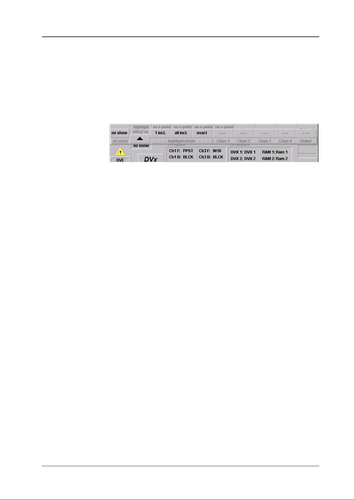
2.3.2 INNER WINDOW
The inner window consists of several sections:
D FX inputs
D FX outputs can be hidded via DVx Settings
D Effect selection (6 x 5 buttons)
D Current effect no. can be hidden via DVx Settings
Input Selection
Input selection for the 4 FX processor channels, click on the according fields for
source selection:
Output Selection
Each channel has a separate source for front and back side, which is automatically
selected, depending on the rotation angle of the channel.
Note:
Keep in mind that the inputs of the DD35’s DVx are also used for the according RAM recoder (DVx1 for RAM recorder1 etc.).
Depending whether the front or the backside of the DVx channel is active,
this source is used for the RAM recorder.
Since a fully equipped FX processor can provide 8 signals in parallel (4x a single
channel DVE plus 4 RAM recorder channels) depending on your configuration, you
can run short in available outputs.
On the main crossbar of the DD35 there are only 4 returns available from the
FX processor, named “DVX1” ... “DVX4”.
For the large (standard) mainframe you can buy a “FX direct RAM Output option”
which gives you 4 more FX processor outputs at the rear panel of the mainframe.
These outputs can be re–entered into free inputs by short looping cables.
DVX1 ... DVX4: click on the according fields to change to another
signal (DVx or RAM recorder)
RAM1 ... RAM4: click on the according fields to change to another
signal (DVx or RAM recorder)
6
Operating Instructions – Rev. 0 / 7.2002
Page 11

Example Settings
Supplement Software Release V3.4.5DD35 Production Switcher
FX direct Ram Output option installed:
Probably your setting will be:
DVX1: DVX1 RAM1: RAM1
DVX2: DVX2 RAM2: RAM2
DVX3: DVX3 RAM3: RAM3
DVX4: DVX4 RAM4: RAM4
Since there is no need to change these settings, you probably will hide the complete FX outputs section (DVx Settings menu).
FX direct Ram Output option not installed:
Since this option is not installed, you should hide the RAM outputs part of the FX
outputs section.
For a fully equipped FX processor your setting could be:
DVX1: DVX1
DVX2: DVX2
DVX3: RAM1
DVX4: RAM3
In this case you still could use all 4 channels of DVE in combiner mode (DVX1 =
DVE video, DVX2 = DVE key) as one DVE or two pairs with superblack (DVX1 =
combiner1 on superblack, DVX2 = combiner2 on superblack) as two independent
DVE’s.
On DVX3 you can access RAM recorder1 – which can be cascaded with RAM recorder2.
On DVX4 you can access RAM recorder3 – which can be cascaded with RAM recorder4.
You can change these settings on the fly by macros or by timelines. T o indicate a
deviation from your default setting you can define your defaults in the DVx Settings
menu.
A deviation will then be highlighted.
Note:
The sources named “RAM1” ... “RAM4” which are available as internal
sources can only be used on the sendbuses to the DVx! When selected here
this will feed the according RAM recorder output directly into the DVx channel in a shortcirciut mode on the FX processor. “RAM1” ... “RAM4” selected
on any other bus will generate full frame white. So be careful when rename
the inputs for the re–entered RAM outputs to not get confused with the inernal names.
Operating Instructions – Rev. 0 / 7.2002
7
Page 12
Supplement Software Release V3.4.5 DD35 Production Switcher
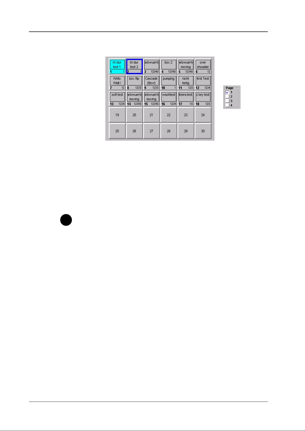
Effect Selection
30 buttons for DVx effect selection (in total 120 effects on 4 pages).
In the bottom part per button you find an indication of the channels used in the ac-
cording effect.
Tip
Current Effect Nr.
To select an effect, first pre–select it (dark blue border) then press OK – or double
click an effect directly.
The selected effect (light blue background) can be controlled by the motion control
buttons or by the DVx digipot on the right side.
The effect selection can be learned in a macro.
Since you can run up to 4 DVx effects simultaneously, learning motion con-
trol commands in macros have to be done carefully.
Pressing the “Play” button while learning a macro, this macro will record a
play command for the first channel in the selected effect.
Example: the effect contains channel 2,3,4 – the macro will record the play
command for channel 2. This macro can be used to play any effect containing
at least channel 2, because a play command for one of the used channels will
play all used channels. So 4 macros is enough to play all effects.
In this section you find an indication of the selected effect per channel. This can
differ from the last recalled effect, since an effect recall only loads the channels included in the DVx effect.
”WB” (workbuffer) means this channel is currently in editmode. This section is only
interesting for users using the DVx as a multi DVE. If you use the DVx channels only
in a single DVE mode, you probably will hide this section.
8
Operating Instructions – Rev. 0 / 7.2002
Page 13
2.3.3 FUNCTION BUTTONS
Highlight eff nr.
This feature is only a help to get a quick overview, which channel is used in which
effect. This is only important for customers using the DVx as a multiple DVE!
The overlay row is special and consists of two parts, which have to be selected independently.
no show no highlighting
1 incl. Highlight all effects which contain at least one of the
all incl. Highlight all effects which contain all of the selected channels.
exact Highlight all effects which contain exactly the selected channels.
Supplement Software Release V3.4.5DD35 Production Switcher
selected channels.
No x–point chan 1 – 4
Refresh
––– / chan 1 toggle selection channel 1: ”– – –” is off, ”chan 1” is on.
––– / chan 2 toggle selection channel 2: ”– – –” is off, ”chan 2” is on.
––– / chan 3 toggle selection channel 3: ”– – –” is off, ”chan 3” is on.
––– / chan 4 toggle selection channel 4: ”– – –” is off, ”chan 4” is on.
––– / global toggle selection global: ”– – –” is off, ”global” is on.
If active, recalling or playing an effect does not recall the sources stored per keyframe for the according channel.
Refresh the display of the menu and reload the workbuffer for editmode.
Operating Instructions – Rev. 0 / 7.2002
9
Page 14

Supplement Software Release V3.4.5 DD35 Production Switcher
Motion Controls:
– Start
– Reverse
– Pause
– Play
– End
Modify
Motion control buttons for selected effect, see below Inner Window, middle part.
Rename rename selected effect
Copy copy selected effect (not yet supported)
Move move selected effect (not yet supported)
Delete delete selected effect
10
Operating Instructions – Rev. 0 / 7.2002
Page 15
2.4 DVX EDIT MENU
Supplement Software Release V3.4.5DD35 Production Switcher
2.4.1 GENERAL CONTROL PRINCIPLES
The edit control consists of 2 rows of 8 index cards.
D You can toggle between the two rows of 8 with the arrow button (top row left).
D To select an index card press the according button in the top row of the GUI
panel.
Most index cards have several pages (functions) with up to 4 controls.
D You can toggle through the functions with the function select button (top row
rigtht of the GUI).
D The up to 4 controls per page can be controlled by the 4 digipots on the right
side.
D Some controls can also be set with numeric values (see below)
Operating Instructions – Rev. 0 / 7.2002
11
Page 16
Supplement Software Release V3.4.5 DD35 Production Switcher
Tip
The tabulators of the index cards indicate the following states:
D Dark blue background: At least one value of the index card is not user default.
D Name of the cards is followed by an asterisk (*), e.g. “2–D *:
At least one value of the index card does not match the according values of the
selected keyframe. In this case you will loose your changes when you press
next / previous keyframe. To keep your changes first select “Modify / Sel. KF”.
D The dark blue index cards, marking a non default are not visible on Windows95
systems.
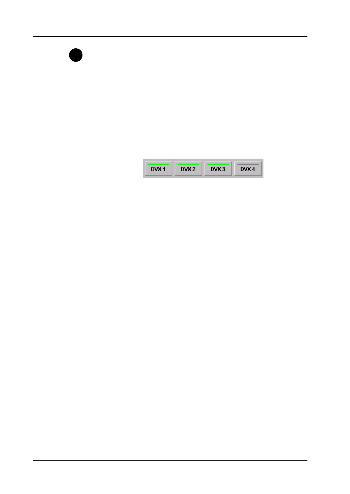
Channel selection:
You can select per local channel whether this channel should be affected by the
global channel. Click the buttons with the mouse to select / de–select. The buttons
are only enabled when the global channel is set to used in the Setup index card.
12
Operating Instructions – Rev. 0 / 7.2002
Page 17

2.4.2 DIALOG BUTTONS
Supplement Software Release V3.4.5DD35 Production Switcher
DVx 1
DVx 2
DVx 3
DVx 4
When selected, the associated channel is preset for function controls.
Since only the values of one channel can be displayed at a time (the colored name
in the inner window),
You may not see a change in values, because e.g. the display is set for the values
of DVx 1, but only DVx 2 and DVx 3 are selected. In this case channel 2 + 3 will
be controlled, but the value change will not be reflected.
To change the channel to be displayed double press (double click) the according
channel. This will put the channel to display and deselect all other channels.
Depending on the type of index card the channel to be displayed can only be channel 1 – 4 (local channel) or global channel. If you select an index card of that type,
the channel to be displayed is forced accordingly.
Forced local channel:
D INPUT
D 2–D
D 3–D
D CROP
D KEY
Previous Menu
D COLORS
D COMBINER
Forced global channel:
D PRIORITY
D CUBE/SLAB
D GLOBAL
Don’t care:
D COPY
D SAVE/RECALL
D MISC
D TIMELINE
D SETUP
Return to the previous menu. For details refer to section Introduction.
Operating Instructions – Rev. 0 / 7.2002
13
Page 18
Supplement Software Release V3.4.5 DD35 Production Switcher
2.4.3 FUNCTION BUTTONS
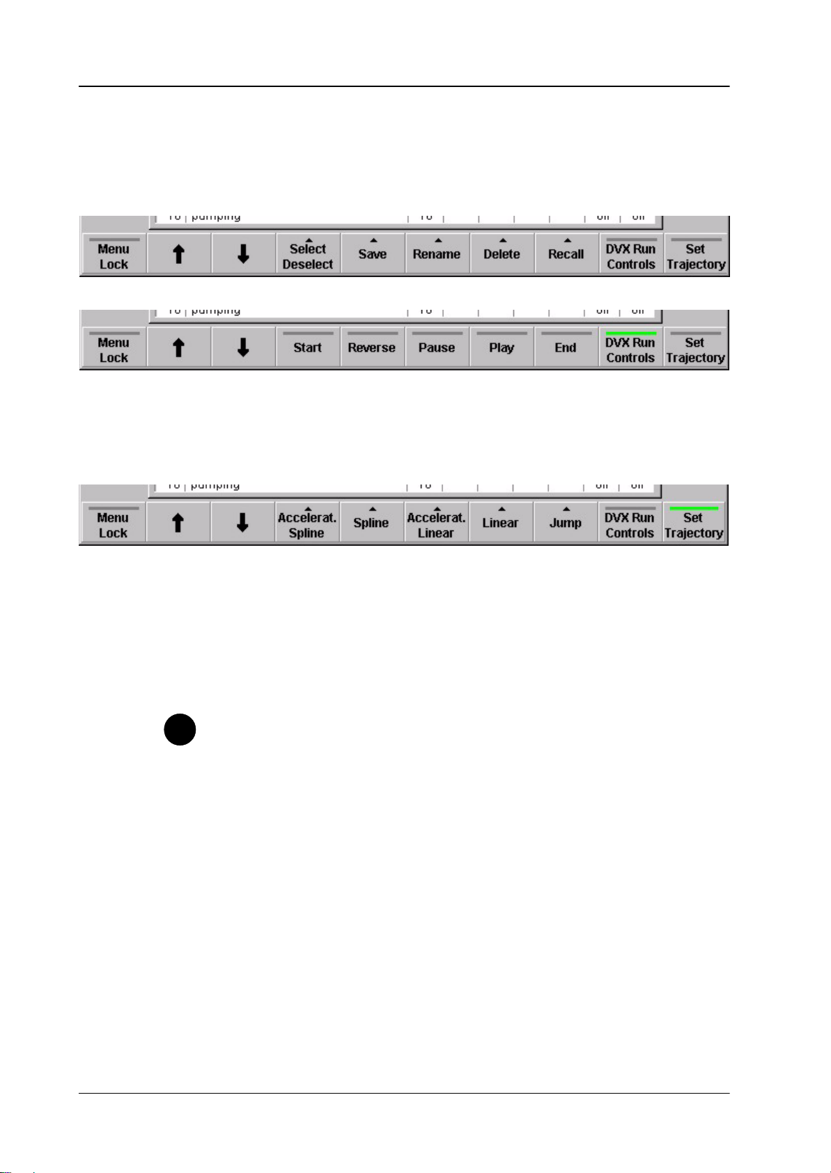
DVx Run Control
Standard editing controls
Motion controls
Set Trajectory
Trajectory controls
Toggles bottom row controls between standard editing controls and motion controls:
Toggles bottom row controls between standard editing controls and trajectory controls:
Tip
“Arrow Up” and “Arrow Down” (in Timeline “Arrow Left” and “Arrow Right”):
Go to next / previous keyframe.
Some of the bottom controls refer to the “selected” control (the control box
with light blue background)
There are two ways to change the selected control:
D Touch the according digipot
D Press the button of the selected index card (top row) again to advance the
selection
14
Operating Instructions – Rev. 0 / 7.2002
Page 19
2.4.4 STANDARD EDIT CONTROLS
In general the commands below are executed for the selected channels (with Dialog buttons) only.
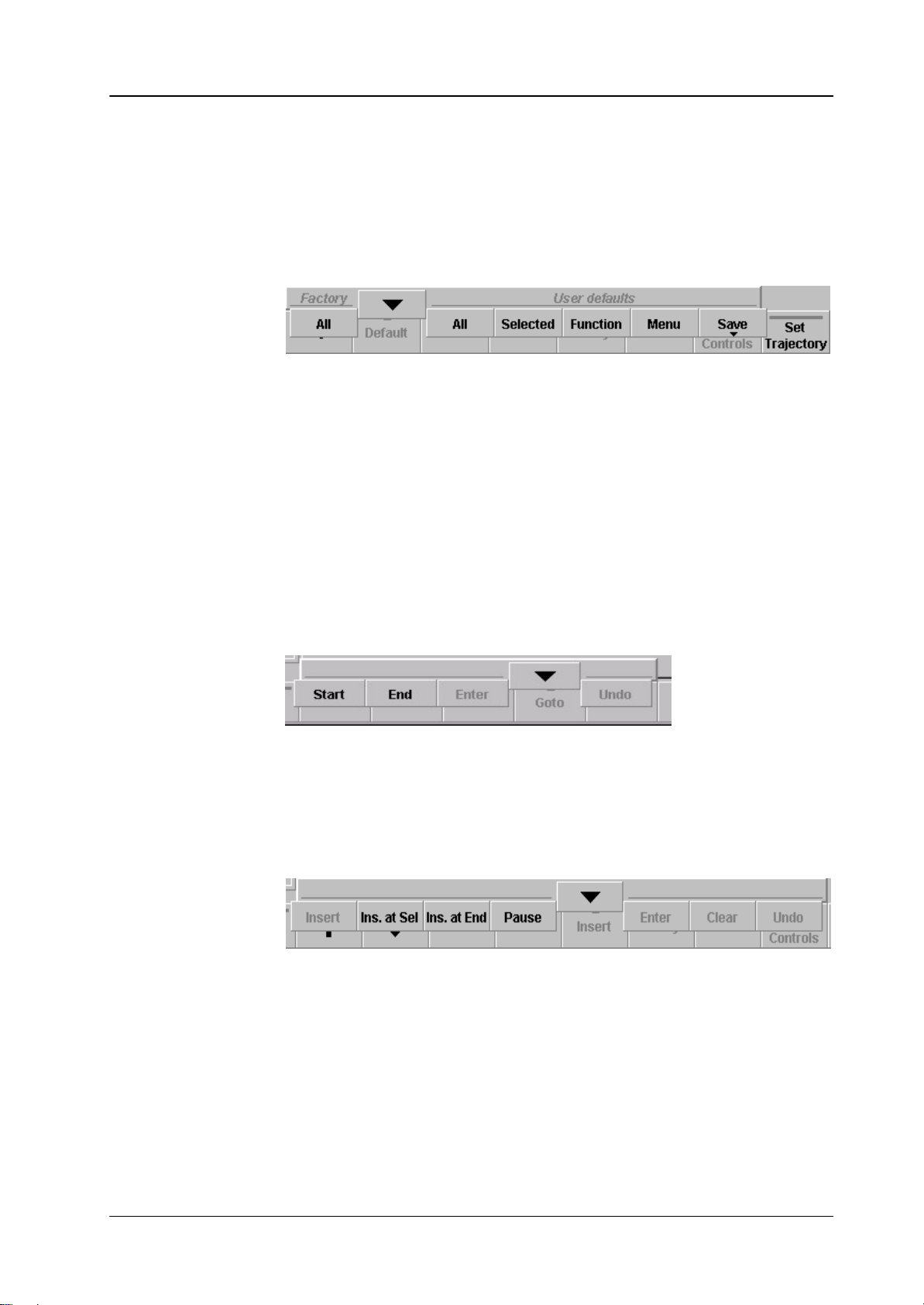
Default
Factory All Sets all values for all selected channels to factory default values.
User default:
All Sets all values for all selected channels to user default values.
Selected Set the selected (light blue) control to user default.
Function Set all controls of a page to user default.
Supplement Software Release V3.4.5DD35 Production Switcher
Goto
Insert
Menu Set all controls of all pages of an index cards.
Save Save the actual values of DVx 1 and the actual values of the
global channel as user default.
Start Go to start of timeline (first keyframe).
End Go to end of timeline (last keyframe).
Other commands not yet supported.
Ins. at Sel Insert actual state as keyframe before the selected keyframe.
Ins. at End Insert actual state as keyframe after the last keyframe.
Pause Insert pause after the last keyframe.
Other commands not yet supported.
Operating Instructions – Rev. 0 / 7.2002
15
Page 20
Supplement Software Release V3.4.5 DD35 Production Switcher
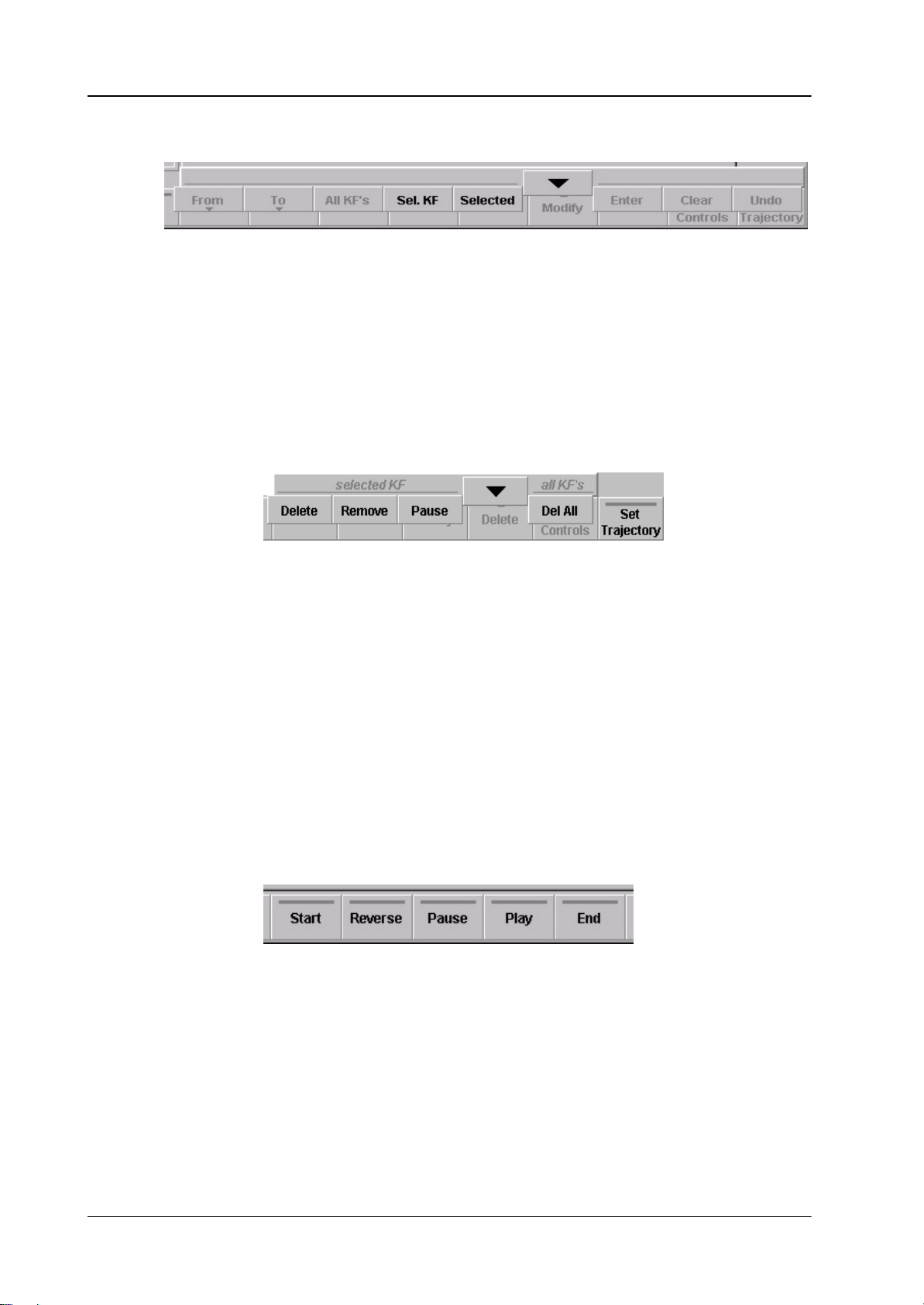
Modify
Sel. KF Modify the selected keyframe
Selected Allows numeric input for geometric parameters.
If you use the keypad in the Master–Ti/ME–Memo section of the
main control panel:
Toggle +/– is the relocate button.
Decimal point is achieved by pressing the digit “8” twice.
Other commands not yet supported
Delete
Delete Delete the selected keyframe. The total duration of the effect will
Remove Same as delete, but the keyframe duration of the deleted keyframe
Pause Deletes the selected Pause.
Delete All Deletes all keyframes. One keyframe always remains with factory
2.4.5 MOTION CONTROLS
Start: Set effect to begin (first keyframe)
Reverse: Play effect in reverse direction
be reduced by the keyframe duration of the deleted keyframe.
If this keyframe is the only one, the values are set to factory default.
is added to the following one, maintaining the total effect length.
default values.
16
Pause: Pause effect
Play: Play effect in normal direction
End: Set effect to end (last keyframe)
Operating Instructions – Rev. 0 / 7.2002
Page 21
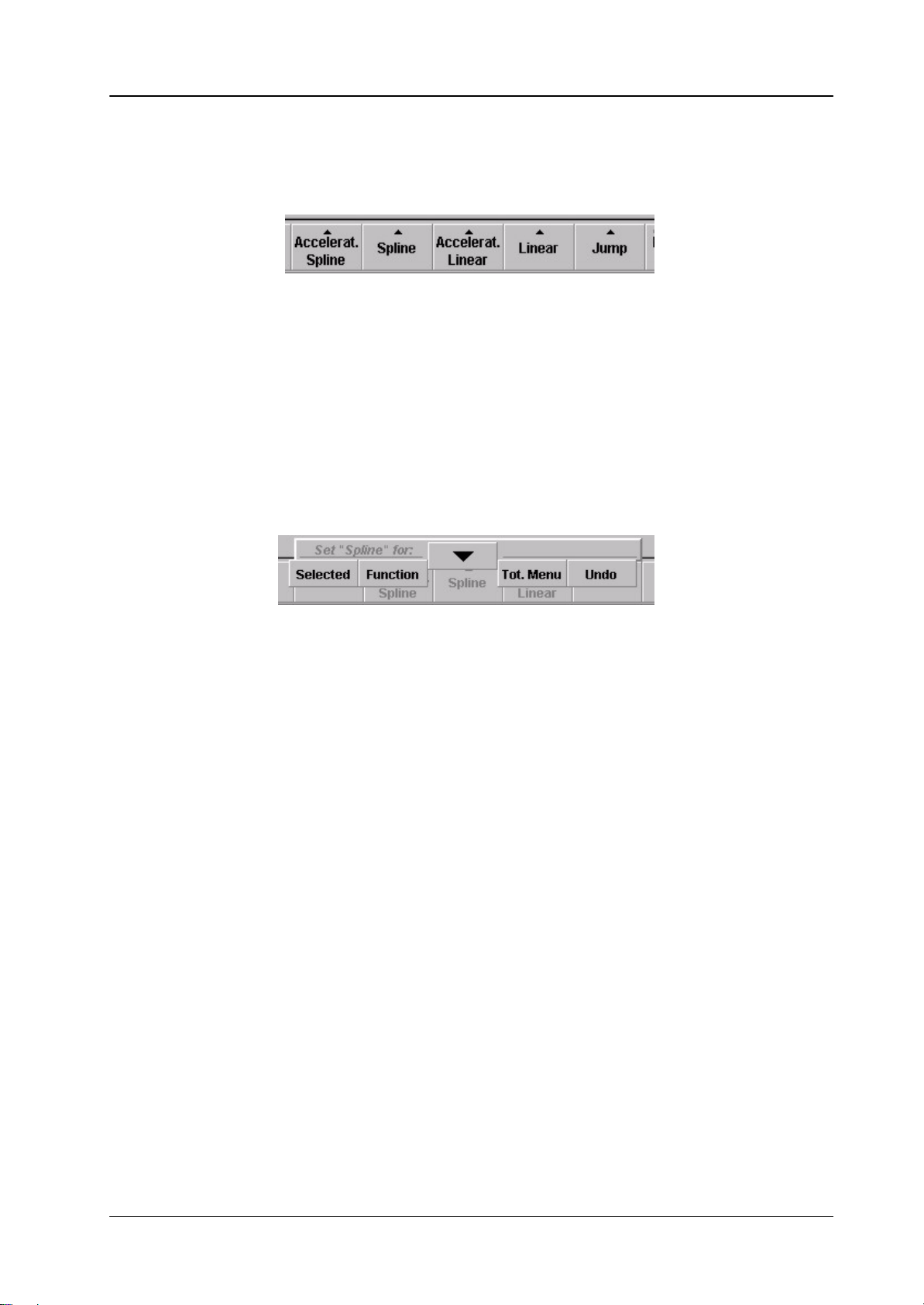
2.4.6 TRAJECTORY CONTROLS
There are 5 types of trajectory for transitions between keyframes:
Accelerated Spline Spline curve with variable speed
Spline Spline curve with constant speed.
Accelerated Linear Linear interpolation with variable speed.
Linear Linear interpolation with constant speed.
Jump: No interpolation at all, just switch to the values
These 5 types can be set selectively:
Supplement Software Release V3.4.5DD35 Production Switcher
(slow start and end).
of the next keyframe.
Selected Set the selected.
Function Set all controls of a page.
Menu Set all controls of all pages of an index cards.
Operating Instructions – Rev. 0 / 7.2002
17
Page 22

Supplement Software Release V3.4.5 DD35 Production Switcher
Jump
Linear
(with constant speed)
Accelerated Linear
(with variable speed,
slow start, slow end)
Spline
(with constant speed)
Accelerated Spline
(with variable speed,
slow start, slow end)
KF2
KF1 KF3
KF2
KF1 KF3
KF2
KF1 KF3
18
Operating Instructions – Rev. 0 / 7.2002
Page 23

2.5 INDEX CARDS
2.5.1 INPUT INDEX CARD
Index card with 3 pages: Front, Back, Mosaic
Supplement Software Release V3.4.5DD35 Production Switcher
Page Front
Page Back
Page General
Front–Src The selected input is set for this keyframe when
the front side of the DVx is visible
Front–Inv ”No” The front source is shown directly
”Horiz.” The front source is horizontally mirrored
”Vert.” The front source is vertically mirrored
”H & V” The front source is horizontally and vertically
mirrored.
Back–Src The selected input is set for this keyframe when
the back side of the DVx is visible
Back–Inv ”No” The back source is shown directly
”Horiz.” The back source is horizontally mirrored
”Vert.” The back source is vertically mirrored
”H & V” The back source is horizontally and vertically
mirrored.
Freeze ”on” Selecting Freeze mode
”off”
Readout Selecting Readout mode
Operating Instructions – Rev. 0 / 7.2002
”field 1”
”field 2”
”frame”
19
Page 24

Supplement Software Release V3.4.5 DD35 Production Switcher
Page Mosaic
Mosaic H Reduces the horizontal resolution.
The result is a block structure
Mosaic V Reduces the vertical resolution.
The result is a block structure
20
Operating Instructions – Rev. 0 / 7.2002
Page 25

2.5.2 2–D INDEX CARD
Index card with 3 pages: Source (Pre–3D), Aspect (Pre–3D), T arget (Post–3D)
Supplement Software Release V3.4.5DD35 Production Switcher
Page Source (Pre–3D)
Page Aspect (Pre–3D)
X–Source x–position in 2–dimensional space prior to 3–D
manipulation for local channel
Y–Source y–position in 2–dimensional space prior to 3–D
manipulation for local channel
Z–Source z–position in 2–dimensional space prior to 3–D
manipulation for local channel
Width–Asp. Stretch / compress image horizontally in 2–dimensional space
prior to 3–D manipulation for local channel
Height–Asp Stretch / compress image vertically in 2–dimensional space
prior to 3–D manipulation for local channel
Size–Asp. Size in 2–dimensional space prior to 3–D manipulation for
local channel
Operating Instructions – Rev. 0 / 7.2002
21
Page 26

Supplement Software Release V3.4.5 DD35 Production Switcher
Page Target (Post–3D)
X–Target x–position in 2–dimensional space after 3–D manipulation
for local channel
Y–Target y–position in 2–dimensional space after 3–D manipulation
for local channel
Z–Target Size in 2–dimensional space after 3–D manipulation
for local channel
Tip
Values of X, Y, and Z Parameters in the 2D Space:
X = Horizontal Axis
Y = Vertical Axis
Z = Rotation Axis
+V
+0.375
–H –0.5
+Z
+0.5 +H
22
–Z
–0.375
–V
Operating Instructions – Rev. 0 / 7.2002
Page 27

2.5.3 3–D INDEX CARD
Index card with 3 pages: Locate, Rotate, Axis
Supplement Software Release V3.4.5DD35 Production Switcher
Page Locate
Page Rotate
Page Axis
X–Locate x–position in 3–dimensional space for local channel
Y–Locate y–position in 3–dimensional space for local channel
Z–Locate z–position in 3–dimensional space for local channel
X–Rotate x–axis rotation in 3–dimensional space for local channel
Y–Rotate y–axis rotation in 3–dimensional space for local channel
Z–Rotate z–axis rotation in 3–dimensional space for local channel
X–Position x–position of the coordinate system for local channel
Y–Position y–position of the coordinate system for local channel
Z–position z–position of the coordinate system for local channel
Operating Instructions – Rev. 0 / 7.2002
23
Page 28

Supplement Software Release V3.4.5 DD35 Production Switcher
2.5.4 CUBE / SLAB INDEX CARD
Index card with seven pages:
Page Box Morph
All commands on this index card are only effective when the global channel is enabled (Setup index card), and when the buttons DVX1 – DVX3 are selected:
If the box–morph value is 0.000 the 3–D parameters of the local channels are used
to position the local channels.
If the value is 1.000 the internal 3–D parameters for the cube–builder are used to
position the local channels.
That means when you run an effect with e.g. keyframe 1 box–morph = 0, and
keyframe 2 box–morph = 1.000 you will first see the 3 channels at their individual
positions, then flying to the positions to form a cube.
Size–X x–size of the cube (should be 1.0 for fullframe)
Size–Y y–size of the cube (should be 0.7 for fullframe)
Size–Z z–size of the cube
24
Operating Instructions – Rev. 0 / 7.2002
Page 29

Supplement Software Release V3.4.5DD35 Production Switcher
Pages 1F–Front
1B – Back
2F–Left
2B–Right
3F–Top
3B–Bottom
These pages allow to crop part and position an image for each side of the cube.
Pos H horizontal start of the image
Pos V vertical start of the image
Size H horizontal size of the image
Size V vertical size of the image
Operating Instructions – Rev. 0 / 7.2002
25
Page 30

Supplement Software Release V3.4.5 DD35 Production Switcher
2.5.5 CROP INDEX CARD
Index card with 3 pages: Crop, Border, Softness–Width
Page Crop / Border / Softness
Crop Soft Set softness for all edge of the image
Border Soft Set border softness for all edge of the image
Cr Width Set crop for all edges of the image simultaneously
B Width Set border for all edges of the image simultaneously
Page Crop per Edge
Crop Left Crop left edge of the image
Crop Top Crop top edge of the image
Crop Right Crop right edge of the image
Crop Bot. Crop bottom edge of the image
Page Border per Edge
Border Left Set width for left edge border of the image
Border Top Set width for top edge border of the image
26
Border Right Set width for right edge border of the image
Border Bot Set width for bottom edge border of the image
Operating Instructions – Rev. 0 / 7.2002
Page 31

2.5.6 KEY INDEX CARD
Index card with one page:
Supplement Software Release V3.4.5DD35 Production Switcher
Page Mode 1/2
V + V Channel 1 and 2 process both a video signal. The key signals for
both channels are generated internally in the DVx. Both channels
can be controlled individually.
V + K In this mode Channel 1 processes the video signal and channel 2
the key signal (flying key mode). Channel 2 can not be controlled
directly, the control parameters of channel 1 are used.
Note:
Since in the actual software also the input source for channel 2 is set by channel 1. This would not allow you to select e.g. ”chargen video” for channel 1
and ”chargen key” for channel 2.
To allow different sources set in the Input index card Inp.–Type to ”no x–pts”.
Page Mode 3/4
V + V Channel 3 and 4 process both a video signal. The key signals for
both channels are generated internally in the DVx. Both channels
can be controlled individually.
V + K In this mode Channel 3 processes the video signal and channel
4 the key signal (flying key mode). Channel 4 can not be controlled
directly, the control parameters of channel 3 are used.
Note:
Since in the actual software also the input source for channel 4 is set by channel 3. This would not allow you to select e.g. ”chargen video” for channel 3
and ”chargen key” for channel 4.
To allow different source set in the Input index card Inp.–T ype to ”no x–pts”.
Operating Instructions – Rev. 0 / 7.2002
27
Page 32

Supplement Software Release V3.4.5 DD35 Production Switcher
2.5.7 GLOBAL INDEX CARD
Index card with 3 pages: Locate, Rotate, Axis
Page Locate
Page Rotate
Page Axis
X–Locate x–position in 3–dimensional space for global channel.
Y–Locate y–position in 3–dimensional space for global channel.
Z–Locate z–position in 3–dimensional space for global channel.
X–Rotate x–axis rotation in 3–dimensional space for global channel.
Y–Rotate y–axis rotation in 3–dimensional space for global channel.
Z–Rotate z–axis rotation in 3–dimensional space for global channel.
X–Position x–position of the coordinate system for global channel
Y–Position y–position of the coordinate system for global channel
Z–position z–position of the coordinate system for global channel
28
Operating Instructions – Rev. 0 / 7.2002
Page 33

2.5.8 COLORS INDEX CARD
Index card with four pages: Matte 1
Supplement Software Release V3.4.5DD35 Production Switcher
Neu
Page Matte 1 / 2
Page Wash
Saturation Range 0.000 through 1.000, saturation of the border color
Luminance Luminance of the border color fo matte 1 / 2
0.000: black
0.500: full color saturation
1.000: white
Hue Hue of the border color. The range for a full color circle is
0.000 through 1.000.
Larger values than 1.000 allow more than one full color change
between keyframe transitions
Angle Adjusting the angle of the wash.
Position H Adjusting the H position of the wash.
Position V Adjusting the V position of the wash.
Softness Adjusting the softness of the wash.
Operating Instructions – Rev. 0 / 7.2002
29
Page 34

Supplement Software Release V3.4.5 DD35 Production Switcher
Page Mode
Matte 1 Select matte 1 as color.
Matte 2 Select matte 2 as color.
Wash Select the Wash mode. In this mode the trenstion beteen the two
colors run can be adjusted with “Angle”, and H/V Position in the
“Wash” page.
Split Select the Split mode. In this mode the wash is within the border.
30
Operating Instructions – Rev. 0 / 7.2002
Page 35

2.5.9 COMBINER INDEX CARD
Index card with two pages:
Supplement Software Release V3.4.5DD35 Production Switcher
Page General
Opacity Opacity for local channel.
Z–Offset Z–offset for this channel. Only effective if the priority for
this channel is set to Z–key in the Priority index card.
Page Background Blacklevel
Chan 1 ... 4 black / superblack
Every time you change the architecture for your effect (single, pair1/2, pair3/4, triple, quadruple), the background blacklevels for the according channels are set automatically:
D For single to superblack (allowing to work with just one output without a key
channel).
D For pair1/2, pair3/4, triple, quadruple to black (using 2 outputs – video+key)
If you have a fully equipped FX processor without RAM output option – that means
only DVX1 ... 4 as outputs available – you can have e.g. two pairs with superblack
on DVX1 and DVX3, using DVX2 and DVX4 as RAM recorder outputs at the same
time. Overwrite chan1 and chan3 to superblack AFTER you have set your architecture.
Operating Instructions – Rev. 0 / 7.2002
31
Page 36

Supplement Software Release V3.4.5 DD35 Production Switcher
2.5.10 COPY INDEX CARD
This index card is not yet supported in the actual software version!
32
Operating Instructions – Rev. 0 / 7.2002
Page 37

2.5.11 PRIORITY INDEX CARD
Index card with one pages:
Supplement Software Release V3.4.5DD35 Production Switcher
All commands on this index card are only effective when the global channel is enabled (Setup index card)
Channel 1 Set the combiner priority for channel 1.
If the channel priority is lower than another channels, the channel number (”1”) is
left of the other numbers, separated by a dash (”–”). If the channel has z–priority
with other channels, these channels are not separated by a dash and highlighted
with yellow background.
Example: 4 – 12 – 3
This indication means: channel 4 has the lowest priority, channel 1 and 2 are together in one group of z–priority, but this group has always a higher priority than
channel 4 and a lower priority than channel 3.
Channel 2 See channel 1
Channel 3 See channel 1
Channel 4 See channel 1
Operating Instructions – Rev. 0 / 7.2002
33
Page 38

Supplement Software Release V3.4.5 DD35 Production Switcher
2.5.12 SAVE / REC INDEX CARD
Index card with one page
Register Select register for
”Save”
”Rename”
”Delete” (not yet implemented)
”Recall”
”Protect”
”Loop” (not yet implemented)
Protect
”on”: register cannot be saved, renamed, or deleted
”off”: all operations are allowed
Loop ”on”: effect runs endlessly in loop (not yet implemented)
”off”: effect runs once (not yet implemented)
In the listbox per effect the number of keyframes per channel is listed.
Note: doppelclick an effect in listbox recalls effect autom.
34
Operating Instructions – Rev. 0 / 7.2002
Page 39

2.5.13 MISC INDEX CARD
Index card with one page:
Supplement Software Release V3.4.5DD35 Production Switcher
Filter
When a DVx channel is sized, higher frequencies are automatically filtered to avoid
moiré effect. If you still find moiré in some very critical signals you can adapt it
manually by this parameter.
This parameter can also be used the generate a slight defocus. You can cascade
more channels to increase the defocus range. For stills you can also increase the
defocus range by using one channel recursively (e.g. feed DVx1 with signal from
DVx1) and going to freeze before the image is completely blured.
Chan.–Ident
To indicate the number and front/back information of a channel you can insert an
ident per channel (e.g. ”2F” = channel 2 front) in different sizes:
D hidden
D small
D medium
D large
D extra large
Operating Instructions – Rev. 0 / 7.2002
35
Page 40

Supplement Software Release V3.4.5 DD35 Production Switcher
Start Speed/ End Speed
If you have selected ”accelerated spline” or ”accelerated linear” as trajectory
between keyframes, these two parameters define the amount of acceleration.
”0.000” = strongest acceleration.
”1.000” = constant speed.
Start Speed Acceleration at the begin of the movement.
End Speed Acceleration at the end of the movement.
36
Operating Instructions – Rev. 0 / 7.2002
Page 41

2.5.14 TIMELINE INDEX CARD
Index card with 2 pages: Timeline, View
Supplement Software Release V3.4.5DD35 Production Switcher
Page Timeline
Page View
TL–Offset Set timeline offset for selected channel.
Via ”Modify / Selected” you can enter absolute timecode
TL–Dur Will set the duration for the total timeline.
Not yet implemented in the actual software.
KF–Dur Set the duration for the selected keyframe.
Via ”Modify / Selected” you can enter absolute timecode
Eff.–Pos Moves the actual position (cursor) in the timeline.
Zoom Set the zoom window for the display
Scroll Set the start timecode for the display.
Eff.–Pos Moves the actual position (cursor) in the timeline.
(same as in ”page timeline”)
With the left / right arrow at the bottom you step to the previous / next keyframe for
the DISPLAYED channel.
Operating Instructions – Rev. 0 / 7.2002
37
Page 42

Supplement Software Release V3.4.5 DD35 Production Switcher
2.5.15 SETUP INDEX CARD
Index card with 1 pages: Local Channels
Page Local Channels
Channel 1 – Channel 4
When you start creating an effect in the workbuffer, this is the first page to set.
The possible modes per channel are:
F unused
F single
F pair
F triple (not for channel 4)
F quadruple
If you decide to use the DVx like you would use an external DVE – just as one device
– your choice will always be quadruple. When you only need two channels for a
certain ef fect, just set the size of the channels not necessary to zero. But in this case
you only can use one DVx effect at a time.
When you want to use the DVx as multiple independent DVEs, only select the
channels needed – to leave the other ones available for other, simultaneously
recalled effects.
38
Operating Instructions – Rev. 0 / 7.2002
Page 43

Supplement Software Release V3.4.5DD35 Production Switcher
Depending on the channel setup (architecture) the resulting video signal is available on the following DVx outputs:
Channel 1:
Single: DVX1 (video on superblack)
Pair 1 / 2: Combiner output video DVX 1, combiner output
key DVX 2.
Triple: Combiner output video DVX 1, combiner output
key DVX 2.
Quadruple: Combiner output video DVX 1, combiner output
key DVX 2.
Channel 2:
Single: DVX2 (video on superblack)
Pair 1 / 2: Combiner output video DVX 1, combiner output
key DVX 2.
Triple: Combiner output video DVX 1, combiner output
key DVX 2.
Quadruple: Combiner output video DVX 1, combiner output
key DVX 2.
Channel 3:
Single: DVX3 (video on superblack)
Pair 3 / 4: Combiner output video DVX 3, combiner output
key DVX 4.
Triple: Combiner output video DVX 1, combiner output
key DVX 2.
Quadruple: Combiner output video DVX 1, combiner output
key DVX 2.
Tip
Channel 4:
Single: DVX4 (video on superblack)
Pair 3 / 4: Combiner output video DVX 3, combiner output
key DVX 4
Triple: not possible on channel 4
Quadruple: Combiner output video DVX 1, combiner output
key DVX 2
The cube–builder always uses channels 1–3, that means, when you want to build
a cube you need a triple – or a quadruple if you want to used a cube (channel 1–3)
and channel 4 as an independent channel, all on one combiner output.
Depending on your channel settings you can run up to 4 DVx effects simultaneously.
Operating Instructions – Rev. 0 / 7.2002
39
Page 44

Supplement Software Release V3.4.5 DD35 Production Switcher
Page Global Channel
The global channel should be set to ”used” if you need:
D the cube/slab builder
D priority settings other than Z–priority
D global 3D–control of more than one channel
If you decide to use the DVx like you would use an external DVE – just as one device
– your choice will always be ”used”.
40
Operating Instructions – Rev. 0 / 7.2002
Page 45

2.6 DVX SETTINGS
Supplement Software Release V3.4.5DD35 Production Switcher
2.6.1 DIALOG BUTTONS
DVE Extern
DVx Main
DVx Edit
DVx Settings
Previous Menu
Operating Instructions – Rev. 0 / 7.2002
Switch to control page for extern DVE 1 + 2.
Switch to the main menu page for internal DVx
Switch to edit page for intern DVx.
Current page.
Return to the previous menu. For details refer to section Introduction.
41
Page 46

Supplement Software Release V3.4.5 DD35 Production Switcher
2.6.2 FX–OUT INDEX CARD
In this indexcard you can set the curent values and your default values for DVX1
... DVX4 and RAM1 ... RAM1.
For more information please see FX–outputs section of DVx Main menu
Bottom row buttons:
Set intern to Default just an easy way to set DVX1 ... DVX4 to default
Set extern to Default just an easy way to set RAM1 ... RAM4 to default
42
Operating Instructions – Rev. 0 / 7.2002
Page 47

2.6.3 VIEW INDEX CARD
Supplement Software Release V3.4.5DD35 Production Switcher
Selected effects per channel: show/hide ”current effect nr.” section in
DVx Main menu
FX intern out settings: show/hide DVX1 – DVX4 part of the ”FX outputs”
section in DVx Main Menu
FX extern out settings: show/hide RAM1 – RAM4 part of the ”FX outputs”
section in DVx Main Menu
Highlight when FX–out actual is not default:
select the color for highlighting a deviation from
default – or gray for no highlighting
Operating Instructions – Rev. 0 / 7.2002
43
Page 48

Supplement Software Release V3.4.5 DD35 Production Switcher
2.6.4 GENERAL INDEX CARD
Edit workbuffer loadmode:
In contrary to other DVE’s the DVx can run effects without loading them into the
workbuffer. This allows editing an effect while running another one at the same time
– as long as there is no channel conflict. If you do not need this feature, you should
select ”load last played one” to simplify operation.
In this mode the behaviour is as follows:
When you enter the DVx Edit menu the last recalled effect from the DVx Main menu
will be automatically loaded into the workbuffer, creating a behaviour which is
similar to other DVE’s.
Note:
When you recall other effects e.g. by macros or timelines while you are in the
DVx Edit Menu, you have to confirm the loading into the workbuffer by a
button in the bottom row (”load last played one”) to avoid unneccessary
loading actions.
To allow editing e.g. an effect using channel 3+4 while running another effect using
channel 1+2 you have to select ”load manually”
In this mode the behaviour is as follows:
When you enter the DVx Edit menu that contents of the workbuffer remains
untouched. You can go on editing the current effect in the workbuffer. If there is a
architecture conflict, that means the last recalled effect on the DVx Main page uses
channels which are also used by the workbuffer, a window is displayed, describing
this conflict situation.
44
Example:
Y ou are editing with a ”Triple” in the workbuf fer and in the DVx Main page you have
recalled en e ffect with a ”Pair 3 / 4”. According to the ”last one wins” philosophy the
”Pair 3 / 4” has stolen channel 3 from your ”Triple” architecture.
Operating Instructions – Rev. 0 / 7.2002
Page 49

Supplement Software Release V3.4.5DD35 Production Switcher
Tip
Your choice is now: (buttons in the bottom row)
Restore: You will re–establish your ”triple”, steeling channel 3 from
”Pair 3/4”. All your keyframes are still available.
New: The workbuffer architecture is set to ”unused” for all channels
(”unused” means the workbuffer does not touch any channel, you
will not disturb any recalled effect) and you can set the architecture
of your choice.
Note:
The keyframes in a channel are not deleted when the architecture is set to
”unused”. This allows you to change the architecture without loosing
keyframe contents. When you want to start from scratch in a channel, select
the channel and press ”Delete / Del All”.
Display channel select mode:
In the edit menu paramaters can only be displayed for one channel at a time. You
can select more than one channel to be controlleded simultaneously.
Allow display of a not controlled channel
In this mode the displayed channel is only changed when a
channel is double clicked or when you click on the DVX name. It is possible e.g.
to control channel 1 only, having channel 2 displayed. You control a channel – but
displayed paramters do not change
Force display to a controlling channel
In this mode the displayed channel is automatically changed to a controlling
channel when the displayed channel is no longer controlled. When you control a
channel you always see the change in the parameters.
Channel 1 ... 4 source recall with DVx effects: Yes / No
If no, recalling or playing an effect does not recall the sources stored per keyframe
for the according channel (same as ”no x–point chan 1 ... 4” on DVx Main page).
Operating Instructions – Rev. 0 / 7.2002
45
Page 50

Supplement Software Release V3.4.5 DD35 Production Switcher
46
Operating Instructions – Rev. 0 / 7.2002
Page 51

3. MEDIA PLAYER MENU
3.1 STATUS MENU
Supplement Software Release V3.4.5DD35 Production Switcher
The Status menu shows the status of up to four “Media Playern“ defined in the
Install / EBox / Machine menu.
Display: Timecode
Note: Dropframe is indicated in the MediaPool format.
Operating Instructions – Rev. 0 / 7.2002
In mark
Out mark
VTR operation mode (Play, Stop, Rewind, ...)
For example
The last colon is replaced by a dot in case of a drop frame.
01:23:12.06
47
Page 52

Supplement Software Release V3.4.5 DD35 Production Switcher
3.1.1 DIALOG BUTTONS
MP Clips
RAM
Previous Menu
3.1.2 FUNCTION BUTTONS
MP1
MP2
MP3
MP4
Grab Mark In
Grab Mark Out
Selecting the Media Player Clip menu.
Selecting the internal RAM Recoder menu.
Return to the previous menu. For details refer to section Introduction.
Selecting the desired machines
Current timecode value of the selected machine is stored as Mark In.
Current timecode value of the selected machine is stored as Mark Out.
Go To
Speeds
Motion control
buttons
Selected machine go to Mark In (Marc Out)
Selecting of the speed control:
Var Variable speed control with Digipot and Fader
Jog Jogging control with Digipot and Trackball
Shuttle Shuttle control with Digipot and Fader
Fast rewind
Play reverse
Stop
Pause
Play forward
Fast forward
48
Operating Instructions – Rev. 0 / 7.2002
Page 53

3.2 MEDIA PLAYER CLIP MENU
Supplement Software Release V3.4.5DD35 Production Switcher
The Media Player Clip menu serves the drive control at VTR. For this purpose, the
buttons in the Motion Control are provided. In addtionen, in this menu the clips list
from a Media Server (e.g. MediaPool, EDIFIES) can be displayed.
3.2.1 DIALOG BUTTONS
MP Status
RAM
Previous Menu
Operating Instructions – Rev. 0 / 7.2002
Selecting the Media Player menu.
Selecting the internal RAM Recoder menu.
Return to the previous menu. For details refer to section Introduction.
49
Page 54

Supplement Software Release V3.4.5 DD35 Production Switcher
3.2.2 DIALOG BUTTONS
Start Clip
Update Cliplist
Autocue
Motion control
buttons
Load the chosen clip from the Media Server
Update Cliplist requests a table of contents of all clips of the Media Server.
This procedure may take some time.
Selected machine jumps to the stored timecode value.
Fast rewind
Play reverse
Stop
Pause
Play forward
Fast forward
50
Operating Instructions – Rev. 0 / 7.2002
Page 55

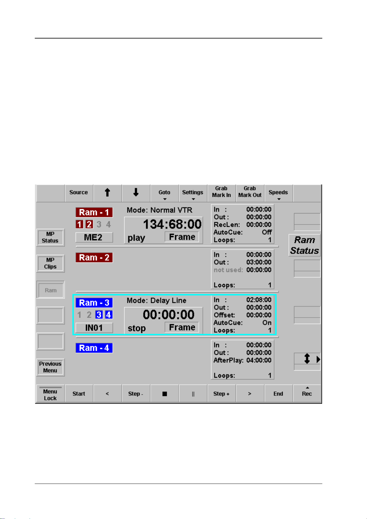
3.3 RAM RECORDER MENU
Supplement Software Release V3.4.5DD35 Production Switcher
The RAM Recorder Module can be installed on the FX Processor (RY 3460) to provide 4 channels of uncompressed video store of 8s each for stills and video sequences.
Note: Channel 1 and channel 2 are fed with the same signal.
Light blue border indicates selected channel
3.3.1 DIALOG BUTTONS
MP Status
MP Clip
Previous Menu
Operating Instructions – Rev. 0 / 7.2002
Selecting the Media Player menu.
Selecting the internal Media Player Clip menu.
Return to the previous menu. For details refer to section Introduction.
Buttons top row:
Channel 3 and channel 4 are fed with the same signal.
51
Page 56

Supplement Software Release V3.4.5 DD35 Production Switcher
3.3.2 DIALOG BUTTONS
Source
Up / Down Arrow
Goto
Settings
Select source for selected channel
Note: Channel 1 and channel 2 are fed with the same signal.
Channel 3 and channel 4 are fed with the same signal.
Move cursor for selected machine up/down
Start Goto to start of timecode (or Mark In point if in clipmode,
loopmode).
End Goto to end of timecode (or Mark Out point if in clipmode,
loopmode).
Timecode Goto to entered timecode.
Mark In Goto to Mark In point.
Mark Out Goto to Mark Out point.
Auto Cue Switch Auto Cue On/Off (not yet supported in this SW–version).
Loops Number of loops for “Simple Loop” or “Extended Loop” mode
Readout set readout for still and for play (see detailed description
“Readout”).
Mode Set operational mode of RAM recorder channel.
Mark In Set Mark In point.
Mark Out Set Mark Out point.
Offset Set offset.
This value is used different purposes, depending on the
operational mode of the RAM recorder.
Grab Mark In
Grab Mark Out
Settings
Start
52
Copy actual timecode to Mark In point.
Copy actual timecode to Mark Out point.
Variable: Set RAM recorder to variable speed and allow speed change
by digipot.
Jog: Set RAM recorder to jog mode and allow jogging by digipot.
Goto to start of timecode (or Mark In point if in clipmode, loopmode).
Operating Instructions – Rev. 0 / 7.2002
Page 57

Supplement Software Release V3.4.5DD35 Production Switcher
Motion control
buttons
End
Rec
Readout Options
Play reverse
Step – Single step back (see detailed description “Readout”)
Stop Show E–E signal
Still
step + Single step forward (see detailed description “Readout”)
Play forward
Goto to end of timecode (or Mark Out point if in clipmode, loopmode)
Record selected signals
You can setup the readout per channel differently for play mode and still mode.
Play mode is normally set to “Frame”, but “Field1” or “Field2” will generate film-
look.
Still mode is set to “Field1” or “Field2” to avoid motion jitter.
Special readout F1/F2
In still mode single step goes per field, that means, field1, field2, field1, field2, etc.In
play mode frames can be played out in “wrong field sequence, that means, first field
“Field2” of a frame, next field “Field1” of the next frame.
This can be used to correct sequences recorded in wrong field order.
Operating Instructions – Rev. 0 / 7.2002
53
Page 58
Supplement Software Release V3.4.5 DD35 Production Switcher
Cascading Channels
By clicking the numbers 1, 2, 3, 4 under the title “RAM–1”, etc. you can cascade
2, 3, or 4 channels. By this the resulting time of the combined channels is accordingly increased. To decascade the channels, just click again on the according numbers or click the title “RAM–1” etc.
The following rules apply to cascading:
D The channel with the lowest number is always the master channel. Video input,
video output, operational mode, and readout is used from this channel.
D When you use tape motion commands, the cursor can be positioned on any
RAM recorder of the cascade.
D In Clip mode, Simple Loop mode, and Extended Loopmode the In and Out
points of the selected RAM recorder are used which allows more In and Out
points in cascade mode (see just below).
54
Operating Instructions – Rev. 0 / 7.2002
Page 59

Supplement Software Release V3.4.5DD35 Production Switcher
Operational Mode
Depending on the operational mode, the parameters in the right part of the window
have a different meaning:
Normal VTR:
In: not used for record or play, can only be used as Mark with
“goto Mark In”
Out: not used for record or play, can only be used as Mark with
“goto Mark Out”
RecLen: record length for record (00:00:00 is unlimited)
AutoCue: not yet supported in the SW–option
Loops: not used here
In this mode you can access the total TCrange of a channel or cascade. Recording
starts at the actual timecode and continues for the number of frames indicated in
“RecLen”.
Clip mode:
In: start of the clip
Out: end of the clip
not used: not used
AutoCue: not yet supported in the SW–option
Loops: not used here
All tape motion commands are limited to the TC range within In and Out timecode.
A play command will automatically play from In to Out point.
Simple Loop:
In: start of the loop
Out: end of the loop
not used: not used
AutoCue: not yet supported in the SW–option
Loops: number of loops, 0 is endless
All tape motion commands are limited to the TC–range within In– and Out–time-
code. A play command will automatically play from In– to Out–point and repeat this
for the number of loops.
Operating Instructions – Rev. 0 / 7.2002
55
Page 60

Supplement Software Release V3.4.5 DD35 Production Switcher
Extended Loop:
In: start of the loop
Out: end of the loop
AfterPlay: time to be played after Out timecode
AutoCue: not yet supported in the SW–option
Loops: number of loops, 0 is endless
This mode allows to start outside (before the loop), providing a kind of “leader”.
Once inside the TC range of the loop, the handling is like in “Simple Loop”. When
the loop is finished, it continues playing after the loop for the time indicated in “AfterPlay”.
Delay Line:
In: not used here
Out: not used here
Offset: delay offset
AutoCue: not yet supported
Loops: not used here
Once set to record, the playout of the channel is delayed by the time indicated by
“Offset”. Since the channel will record endlessly in a circle, the maximum delay is
the record length of the channel (or the cascade).
Live Slomo:
In: not used here
Out: not used here
Offset: replay offset
AutoCue: not yet supported
Loops: not used here
Once set to record, the playout of the channel is real time E/E, that means not
delayed. The channel will record endlessly . Any other tape motion command than
record will stop recording, leaving the full record length of a channel (or a cascade)
for e.g. slomo playback. When record stops, the channels goes back in time indicated by “Offset”.
56
Operating Instructions – Rev. 0 / 7.2002
Page 61

4. MACRO VIEWER AND EDITOR
4.1 ATTACHED MACROS MENU
Supplement Software Release V3.4.5DD35 Production Switcher
4.2 DIALOG BUTTONS
Config
E-Box
Attached Macros
Allocate Panel
Previous Menu
Operating Instructions – Rev. 0 / 7.2002
Selecting Config menu.
Selecting Config E-Box menu.
Selecting Attached Marcro menu.
Selecting Allocate Panel menu.
Return to the previous menu. For details refer to section Introduction.
57
Page 62

Supplement Software Release V3.4.5 DD35 Production Switcher
4.3 VIEWER FOR ATTACHED MACROS
This menu can be accessed in two ways:
D via Config / Attached Macros menu
D by clicking to “attached macros” button,
which is visible in all menus at the right side between the middle digipots. This
button is only visible when there is at least one macro attachment. The button
is grey or green, depending on the settings in the menu Personality / Panel
/ MaKE Memo Attachment Playmode.
4.4 PRINCIPLES OF MACRO ATTACHMENT
Macros can be recalled manually via the macro bus row (Keyer row in Program/
Preset) and via the sidepanel. A more sophisticated way is to recall a macro automatically when you press any other button on the panel. Since a normal button has
its own function, you can attach a macro which is executed BEFORE the actual
function (pre–macro) and/or a macro which is executed AFTER the actual function
(post–macro).
The macros are not attached to the physical buttons, but to the logical buttons. That
means, when you attach a macro to the first button in the Aux bus row while the
auxbus delegation is on Aux bus 5 and second page is selected, this macro is only
fired at the button press for this special setting.
Center Position Centers the display and the cursor
Previous Deleg. Toggles the info display backwards through the
different delegations. Only enabled for buttons
with more delegation levels (e.g. Aux bus row
buttons, Keyer section buttons).
Next Deleg. Toggles the info display forwards through the
different delegations. Only enabled for buttons
with more delegation levels (e.g. auxbus row
buttons, keyer section buttons, wipe selection
buttons).
CP–Type The default panel type to display is of course the
actual panel type. You can select all other panel
types in case you want to export your application
to another type of panel. Since panels differ in
button layout some button of type A may not exist
on panel type B. Macro attached to this buttons
will be shown as “not decoded macros” for panel
type B.
58
Operating Instructions – Rev. 0 / 7.2002
Page 63

Supplement Software Release V3.4.5DD35 Production Switcher
Available panel types:
Selects automatically the connected panel type!
Left/Right/Up/Down Arrow Scrolling the display in the according direction.
Zoom In Zoom in display. Starting from a certain zoom
factor the text lables per button are displayed.
Zoom Out Zoom out display.
Show Info
If “on” the “info popup window” is shown whenever the cursor (blue crosshair) is
over a button.
If “off” the “info popup window” is only shown as long as you hold down the left
mouse button on the according button.
The 4 digipots also allow to scroll the display and to move the cursor (blue crosshair).
Operating Instructions – Rev. 0 / 7.2002
59
Page 64

Supplement Software Release V3.4.5 DD35 Production Switcher
Attachment Display
If a macro is attached to a button in a certain section (e.g. Aux row, M/E1 row) this
section is displayed with a yellow background. The buttons with attached macros
are displayed in red.
To see the details of the attachment, move the cursor to the according button (or
click on it) to open the “info popup window”. Here you will see for which delegations
and which pages pre– and/or post–macros are attached with the name and the
number of the macro.
60
Operating Instructions – Rev. 0 / 7.2002
Page 65

5. SOFTWARE PATCH PANEL
The settings for the “so–called” Soft Patch Panel are located in the menu Install
/ EBox / Input. Select the Input index card.
5.1 INPUT INDEX CARD
Index card for setting the input name transfer parameters and the Software Patch
Panel.
Supplement Software Release V3.4.5DD35 Production Switcher
ext. Name: Enable / Disable the name transfer mode with Yes/No
Patched to: Option “Software Patch Panel”:
Software License Key is required!
With the buttons Reset Patch Panel and Patch Panel On/Off
the settings can be activated or resetted.
Router Output: Select the router output channel
Router Level: Select the level of the routing system (e.g. Prosan router)
GPO Preroll: in preparation
Subst. Table: None / SUBSTAB1 ... 15
Selecting a substitution table.
Refer also to Config / Panel / SubstTab menu.
The substitution tables are used for Simulcast mode.
This entry in this index card can only be modified
if in the sidepanel PC‘s registry the value
“USERINTERFACE / INPUT_SUBSTAB_SELECTABLE is set
to “1”.
Operating Instructions – Rev. 0 / 7.2002
61
Page 66

Supplement Software Release V3.4.5 DD35 Production Switcher
6. RSAT MACRO SELECTION
Selection and staring the RSAT macros is possible in the menu Config / Panel.
Select the SatPanel index card.
6.1 SATPANEL INDEX CARD
Index card for selection and starting the RSAT macros.
62
Operating Instructions – Rev. 0 / 7.2002
Page 67

Supplement Software Release V3.4.5DD35 Production Switcher
Operating Instructions – Rev. 0 / 7.2002
63
Page 68

Supplement Software Release V3.4.5 DD35 Production Switcher
64
Operating Instructions – Rev. 0 / 7.2002
 Loading...