

Page 1
Production Switcher
DD10
Operating Instructions
Page 2

Published by
BTS Media Solutions GmbH
Brunnenweg 9
D-64331 Weiterstadt, Germany
P.O. Box 1165
Tel: +49 (0) 6155-870-0
Fax: +49 (0) 6155-870-300
Web Sites
Internet: www.thomsonbroadcast.com
www.imagingsystems.de
Intranet: www.weiterstadt.thmulti.com
Trademarks
All product names mentioned in this manual are the trademarks of their respective owners.
Copyrights
Information in this document is subject to change without notice.
This document and any updates and/or supplemental information, including any copies thereof, cannot be reproduced, neither
communicated to a third party, without written authorization from THOMSON multimedia Broadcast Solutions.
Please notify THOMSON multimedia Broadcast Solutions of any errors in this document. We also would appreciate any comments
you have to improve this manual.
BTS Media Solutions GmbH 2002. All rights reserved.
Page 3
Revision Report
Philips Broadcast
DD 10
Documentation Order Number
Before reading the entire
manual, please check for any
supplements at the end
of the manual.
ItemRev Date Ser
No
1 0 5.93 100 all
2 1 01.95
3 2 06.95
from 220
from 220
Pages affected Contents Remarks
all
Section 2.7
Operating Instructions
Operating Instructions
Software “I”,
Application notes
Keyers panel
000 212 185 900
1st Edition
2nd Edition
3rd Edition
4 3 11.97 all
Software “L”
Key Processor II
General corrections
4th Edition
Page 4

Diamond digital DD10
CONTENTS
Contents
Page
1. General 3
2. Functional
2.1 Source
2.2 Aux
2.3 Dve
2.4 Transition
2.5 Downstream
2.6 Fade-to-black
2.7 Keyers
2.8 Operation
2.9 Mattes
2.10 Wipe
2.11 Masks
2.12 Positioner
2.13 Stores
2.14 Setup 97
2.15 Enabling
2.16 Auto
2.17 Key Memory 111.
. . . . . . . . . . . . . . . . . . . . . . . . . . . . . . . . . . . . . . . . . . . . . . . . . . . . . . .
Description of the Panels5. . . . . . . . . . . . . . . . . . . . . . . . . . . .
Selection Panel5. . . . . . . . . . . . . . . . . . . . . . . . . . . . . . . . . . . .
Buses Panel9. . . . . . . . . . . . . . . . . . . . . . . . . . . . . . . . . . . . . . . . . .
Panel
2.3.1 Notes
2.7.1 Keyer
2.7.2 Hard
2.7.3 Key
2.7.4 Key
2.7.5 Key
2.7.6 Auto
2.7.7 Chroma
2.7.7.1 Automatic
2.7.7.2 Manual
2.7.7.3 Manual
2.7.8 Key
2.7.9 Key
2.7.10 Key
2.7.11 Key
2.7.12 Copying
2.7.13 Key
2.7.14 Notes
2.8.1 Selection
2.8.2 Selection
2.8.3 Selection
2.8.4 Positioning
2.8.5 Ceanup
2.8.6 Selectivity
2.8.7 Chroma
2.8.8 Forground Fade-Menu 54.
2.8.9 Dynachrome-Menu 55
2.9.1 Limitation
Delegation
. . . . . . . . . . . . . . . . . . . . . . . . . . . . . . . . . . . . . . . . . . . . . .
to DVE Control
Panel
. . . . . . . . . . . . . . . . . . . . . . . . . . . . . . . . . . . . . . . . . . . . . . . .
of the Keyer Menus
Panel
Panel
Panel
Panel
Panel
. . . . . . . . . . . . . . . . . . . . . . . . . . . . . . . . . . . . . . . . . . . . . . . . . . .
Editor and Gpi
. . . . . . . . . . . . . . . . . . . . . . . . . . . . . . . . . . . . . . . . .
Keyer Panel
Panel
Delegation
Key T
Modes
Source
Adjustments
Key Adjustment
Optimization in Case of Critical Patterns
Adjustment of the Key Color
Priority
Masking
Preview
Inverting
Borderliner
to the Use of Add and Luminance Key
. . . . . . . . . . . . . . . . . . . . . . . . . . . . . . . . . . . . . . . . . . .
. . . . . . . . . . . . . . . . . . . . . . . . . . . . . . . . . . . . . . . . . . . . .
. . . . . . . . . . . . . . . . . . . . . . . . . . . . . . . . . . . . . . . . . . .
. . . . . . . . . . . . . . . . . . . . . . . . . . . . . . . . . . . . . . . . . . .
. . . . . . . . . . . . . . . . . . . . . . . . . . . . . . . . . . . . . . . . . . .
. . . . . . . . . . . . . . . . . . . . . . . . . . . . . . . . . . . . .
ransition 28.
. . . . . . . . . . . . . . . . . . . . . . . . . . . . . . . . . . . . . .
. . . . . . . . . . . . . . . . . . . . . . . . . . . . . . . . . . . . . .
Key
. . . . . . . . . . . . . . . . . . . . . . . . . . . . . . . . . . . . .
Chroma Key Adjustment
. . . . . . . . . . . . . . . . . . . . . . . . . . . . . . . . . . . . . .
. . . . . . . . . . . . . . . . . . . . . . . . . . . . . . . . . . . . .
. . . . . . . . . . . . . . . . . . . . . . . . . . . . . . . . . . . . .
. . . . . . . . . . . . . . . . . . . . . . . . . . . . . . . . . . . .
Key Settings
of the Keyer Menus
of the Keyer on DD10
of the Keyer on DD20 / DD30
Sizing Softening P/S/S
/ Density and Clip / Gain
Masking
Key Adjust Menu
of the Color T
. . . . . . . . . . . . . . . . . . . . . . . . . . . . . . . . . . . . . . . .
. . . . . . . . . . . . . . . . . . . . . . . . . . . . . . . . . . . . . . . .
. . . . . . . . . . . . . . . . . . . . . . . . . . . . .
. . . . . . . . . . . . . . . . . . . . . . . . . . . . . . . .
. . . . . . . . . . . . . . . . . . . . . . . . . . . . . . . . .
. . . . . . . . . . . . . . . . . . . . . . . . . . . . . .
. . . . . . . . . . . . . . . . . . . . . . . . . . . . . . . . .
. . . . . . . . . . . . . . . . . . . . . . . . . . . . .
. . . . . . . . . . . . . . . . .
. . . . . .
. . . . . . . . . . . . . . . .
. . . . . . . . . . . . . . . . . . . . . . . . . . . . .
. . . . . . . . . . . . . . . . . . . . . . . . . . . . . . . . . .
. . . . . . . . .
. . . . . . . . . . . . . . . . . . . . . . . . . . . .
. . . . . . . . . . . . . . . . . . . . .
. . . . . . . . . . . . . . . . . . . .
. . . . . . . . . . . . .
. . . . . . . . . . . . . . .
. . . . . . . . . . . . . . . . . . .
. . . . . . . . . . . . . . . . . . . . . . . . . . . . . . .
. . . . . . . . . . . . . . . . . . . . . . . . .
. . . . . . . . . . . . . . . . . . . . . . . . . . . .
. . . . . . . . . . . . . . . . . . . . . . . . . . . . . . . .
riangle 60.
. . . . . . . . . . . . . . . . . . . . . . . . . . . . . . . . .
. . . . . . . . . . . . . . . . . . . . .
11.
12.
15.
23.
25.
27.
28.
29.
32.
33.
34.
34.
36.
36.
38.
38.
38.
39.
39.
39.
40.
42.
45.
45.
46.
46.
47.
48.
50.
52.
57.
63.
87.
91.
93.
107.
109.
I
Page 5

Contents
Diamond digital D10
3. Menu
Control
3.1 Short
3.1.1 Control
3.1.2 Operational
3.1.3 Automatic
3.2 Menu
3.3 Status
3.3.1 Indication
3.3.2 Selection
3.3.3 Setting
3.3.4 Setting
3.4 Access
3.4.1
3.4.2
3.4.3
3.4.4
3.4.5
3.4.6
3.4.7
3.5 Install
3.5.1 Setting
3.5.2 Ident
3.5.3 Couple
3.5.4 Configuration
3.5.4.1 User
3.5.5 Configuration
3.5.6 Diagnosis
3.5.6.1 Fader
3.5.7 Aux-panels
3.5.8 GPI
3.6 Disk
3.6.1 Storing
3.6.2 General
3.6.3 Directory
3.6.4 Standard
3.6.5 Contents
3.6.6 Softkeys
3.6.7 Renaming
3.6.8 Making
3.6.9 Deleting
3.6.10 Deleting
3.6.11 Copying
3.6.12 Copying
3.6.13 Copying
3.6.14 Loading
3.6.15 Error
3.7 Transfer
3.8 Masks
3.8.1 Mask
3.8.2 Creating
3.8.3 Adjusting
3.8.4 Creating
. . . . . . . . . . . . . . . . . . . . . . . . . . . . . . . . . . . . . . . . . . . . . . .
Introduction to the Menu Symbols
with Graphic Objects
Aid by Running Light in Keys
Analogue V
Overview
Menu
Menu
Selection of the Electronics Box
Entering new Users and User Access Rights
Login of a User
Entering and Changing a Password
Assignment of User Access Rights
to the Electronics Box
Locking the Control Panel
Leaving the Access Menu
Menu
and File Menus
Menu
Menu
. . . . . . . . . . . . . . . . . . . . . . . . . . . . . . . . . . . . . . . .
. . . . . . . . . . . . . . . . . . . . . . . . . . . . . . . . . . . . . . . . . .
of the Mixing Level Status
of Submenus
the Fader Curve
the Faders
. . . . . . . . . . . . . . . . . . . . . . . . . . . . . . . . . . . . . . . . . .
. . . . . . . . . . . . . . . . . . . . . . . . . . . . . . . . . . . . . . . . . . .
the Screen Saver
Input Submenu
Submenu
Panel Submenu
Programmable Keys
E-box Submenu
Submenu
Adjust
Submenu
and Recalling Data with Floppy Disk
Directories (Mkdir)
Messages
Delegation
. . . . . . . . . . . . . . . . . . . . . . . . . . . . . . . . . . . .
Submenu
. . . . . . . . . . . . . . . . . . . . . . . . . . . . . . . . . . . .
Information on File Menu
Structure of the Switcher
Files in File Menu
of Directory Windows
for Menu Control
Files and Devices
and Resetting Files
and Resetting Directories
Files
Directories
User-specific Files
Backup Files (Auto Load)
. . . . . . . . . . . . . . . . . . . . . . . . . . . . . . . . . . . . . . . . .
. . . . . . . . . . . . . . . . . . . . . . . . . . . . . . . . . . . . . . . . . .
a Box Mask
the Mask Position
a Wipe Mask
alue Indication in Menu
. . . . . . . . . . . . . . . . . . . . . . . . . .
. . . . . . . . . . . . . . . . . . . . . . . . . .
. . . . . . . . . . . . . . . . . . . . . . . . . . . . . . .
. . . . . . . . . . . . . . . . . . . . . . . . . . . . . . . . .
. . . . . . . . . . . . . . . . . . . . . . . . . . . .
. . . . . . . . . . . . . . . . . . . . . . . . . . . .
. . . . . . . . . . . . . . . . . . . . . . . . . . . . . . . .
. . . . . . . . . . . . . . . . . . . . . . . . . . . . .
. . . . . . . . . . . . . . . . . . . . . . . . . . . .
. . . . . . . . . . . . . . . . . . . . . . . . . . . . . . . . . .
. . . . . . . . . . . . . . . . . . . . . . . . . . . . . . . . . . .
. . . . . . . . . . . . . . . . . . . . . . . . . . . . . .
. . . . . . . . . . . . . . . . . . . . . . . . . . . . . . . . .
. . . . . . . . . . . . . . . . . . . . . . . . . . . . . . . .
. . . . . . . . . . . . . . . . . . . . . . . . . . . .
. . . . . . . . . . . . . . . . . . . . . . . . . .
. . . . . . . . . . . . . . . . . . .
. . . . . . . . . . . . . . . . . . . . . .
. . . . . . . . . . .
. . . . . . .
. . . . . . . . . . . . . . .
. . . . . . . . . . . . . . . . . . .
. . . . . . . .
. . . . . . . . . . . . . . . .
. . . . . . . . . . . . . . . . . . . . . . . .
. . . . . . . . . . . . . . . . . . . . . . . .
. . . . . . . . . . . . . . . . . . . . . . . . .
. . . . . . . . . . . . . . . . . . . .
. . . . . . . . . . . . . . . . . . . . . . . .
. . . . . . . . . . . . . . . . . . . .
. . . . . . . .
. . . . . . . . . . . . . . . . .
. . . . . . . . . . . . . . . . .
. . . . . . . . . . . . . . . . . . . . . . .
. . . . . . . . . . . . . . . . . . . .
. . . . . . . . . . . . . . . . . . . . . . . .
. . . . . . . . . . . . . . . . . . . . . .
. . . . . . . . . . . . . . . . . . . . . . . .
. . . . . . . . . . . . . . . . . . . . . .
. . . . . . . . . . . . . . . . .
. . . . . . . . . . . . . . . . . . . . . . .
. . . . . . . . . . . . . . . . .
. . . . . . . . . . . . . . . . . . . . . .
113.
115.
115.
116.
117.
119.
121.
122.
123.
124.
125.
127.
128.
129.
131.
132.
133.
135.
136.
137.
137.
139.
141.
143.
152.
154.
160.
165.
166.
170.
173.
173.
175.
175.
177.
180.
182.
184.
186.
187.
188.
189.
191.
192.
192.
193.
195.
199.
200.
200.
201.
201.
II
Page 6

Diamond digital DD10
Contents
3.8.5 Creating
3.8.6 Other
3.9 Stores
3.10 GPI-AC
3.11 Bus
3.12 Input
3.13 Keyers
4. Extra 221
4.1 Extra
4.2
4.3 Basic
Menu
3.9.1 Store
3.9.2 Field
3.9.3 Freeze 207
3.9.4 Storing
3.9.5 Matte
3.9.6 Mask
3.9.7 Paint
menu
3.10.1 GPI
3.10.2 GPI
Correction Menu
Correction Menu
Menu
. . . . . . . . . . . . . . . . . . . . . . . . . . . . . . . . . . . . . . . . . . . . . . . . . . . . . . . .
Panel
4.1.1 Display 225
4.1.2 Define
4.1.3 Relocating
(DD20 / DD30 only)
4.1.4 Enabling
4.1.5 Selecting
4.1.6 Selecting
4.1.7 Storing
4.1.8 Generating a Timeline 232.
4.1.9 Components
4.1.10 Modifying a T
4.1.10.1 Changing
4.1.10.2 Changing
4.1.10.3 Changing
4.1.10.4 Changing
4.1.10.5 Inserting
4.1.10.6 Inserting
4.1.10.7 Deleting
4.1.11 Recalling
4.1.12 Deleting
Basic Functions Store, Recall
4.2.1 Using
4.2.1.1 Storing
4.2.1.2 Recalling
(DD10: Data Monitor Required)
4.2.1.3 Dissolve 253
4.2.2 Using
(Extra ME Operation, DD20 / DD30 only)
4.2.2.1 Recalling
4.2.2.2 Dissolve 257
4.2.3 Using
(DD20 / DD30 only)
4.2.3.1 Storing
4.2.3.2 Recalling
Functions Record and Play
a Mask from Mask Store
Setting Options
. . . . . . . . . . . . . . . . . . . . . . . . . . . . . . . . . . . . . . . . . .
Delegation
and Frame Mode
. . . . . . . . . . . . . . . . . . . . . . . . . . . . . . . . . . . . . . . . . .
a V
ideo Picture (V
Store
Store
Mode Masking
Input
Output
. . . . . . . . . . . . . . . . . . . . . . . . . . . . . . . . . . . . . . . . . . . .
the Extra Menu
the Source Selection Keys
the Keys in the Extra Panel
. . . . . . . . . . . . . . . . . . . . . . . . . . . . . . . . . . . . .
. . . . . . . . . . . . . . . . . . . . . . . . . . . . . . . . . . . . .
. . . . . . . . . . . . . . . . . . . . . . . . . . . . . . . . . . . . . . . . .
. . . . . . . . . . . . . . . . . . . . . . . . . . . . . . . . . . . . . . .
. . . . . . . . . . . . . . . . . . . . . . . . . . . . . . . . . . . . .
. . . . . . . . . . . . . . . . . . . . . . . . . . . . . . . . . . .
. . . . . . . . . . . . . . . . . . . . . . . . . . . . . . . . . .
. . . . . . . . . . . . . . . . . . . . . . . . . . . . . . . . . . . . . . . . . .
. . . . . . . . . . . . . . . . . . . . . . . . . . . . . . . . . . . . . . . . . .
Memo in Extra Panel (DD20 / DD30 only)
to a Dif
and Disabling Bank Mode
a Register During Storing
a Register During Recalling
a Snapshot
of a T
imeline in the Extra panel
the Hold T
the T
the T
a Keyframe
a New Keyframe (INSert)
a Loop in a T
a Keyframe
Snapshot or T
Snapshots and T
Snapshots in Menu
Snapshots in Menu
. . . . . . . . . . . . . . . . . . . . . . . . . . . . . . . . . . . . . . . . .
Snapshots
. . . . . . . . . . . . . . . . . . . . . . . . . . . . . . . . . . . . . . . . .
Snapshots
Snapshots
. . . . . . . . . . . . . . . . . . . . . . . . . . .
. . . . . . . . . . . . . . . . . . . . . . . . . . . . . . . .
. . . . . . . . . . . . . . . . . . . . . . . . . . .
ideo Store)
. . . . . . . . . . . . . . . . . . . . . . . . . . . . .
ferent Mixing Level
. . . . . . . . . . . . . . . . . . . . . . . . . . . . . .
. . . . . . . . . . . . . . . . . . . . . . . . . . . . . .
. . . . . . . . . . . . . . . . . . . . . . . . . . .
imeline 234.
. . . . . . . . . . . . . . . . . . . . . . . . . . . . . . .
. . . . . . . . . . . . . . . . . . . . . . . .
ime 238.
ransition T
rajectory 240.
imeline 243.
. . . . . . . . . . . . . . . . . . . . . . .
imeline
imelines 248.
. . . . . . . . . . . . . . . . . . . . . . . . . . .
. . . . . . . . . . . . . . . . . . . . . . . . . . .
. . . . . . . . . . . . . . . . . . . . . . .
. . . . . . . . . . . . . . . . . . . . . . . . . . . . .
. . . . . . . . . . . . . . . . . . . . . . . . . . . . . .
. . . . . . . . . . . . . . . . . . . . . . . . . . . . .
. . . . . . . . . . . . . . . . . . . . . . . .
. . . . . . . . . . . . . . . . .
. . . . . . . . . . . . . .
. . . . . . . . . . . . . . . .
. . . . . . . . . . . . . . . .
. . . . . . . . . . . . . .
. . . . . . . . . . . . .
. . . . . . . . . . . . . . . . . . . .
ime 239.
. . . . . . . . . . . . . . .
. . . . . . . . . . . . . . . . . . . .
. . . . . . . . . . . . . . . . . . . . . .
. . . . . . . . . . .
. . . . . . . . . . . . . . .
. . . . . . . . . . . . . . . . . . .
. . . . . . . . . . . . . . . . .
. . . . . . . . . . . . . . . . . . .
. . . . . . . . . . .
. . . .
202.
202.
205.
206.
206.
207.
207.
208.
209.
211.
211.
213.
215.
217.
219.
223.
226.
227.
229.
229.
230.
231.
236.
241.
242.
245.
246.
249.
249.
251.
252.
254.
256.
258.
258.
259.
261.
III
Page 7

Contents
Diamond digital D10
4.3.1 Creating a T
4.3.2 Playing a T
4.3.3 Recording a T
4.4 Basic
4.5 Other
4.6 Extra
4.7 Trajectory 305
4.8 Error
4.9 Extra-VTR-Protokoll 315
Functions Play
Functions in the Extra Menu
4.5.1 Delete 267
4.5.2 Assign 268
4.5.3 Rename
4.5.4 Define
4.5.5 Show
Editor
4.6.1 Modifying a T
4.6.2 Creating
4.6.3 Overview
4.6.4 Overview
4.6.5 Notes
. . . . . . . . . . . . . . . . . . . . . . . . . . . . . . . . . . . . . . . . . . . . . .
4.7.1 Tens (Tension) 308.
4.7.2 Bias 309
4.7.3 Continuity 310
4.7.4 Weight 311
Messages
imeline with Edit
ileline in Menu
imeline in Menu
, Autoplay and Fader Play
. . . . . . . . . . . . . . . . . . . . . . . . . . . . . . . . . . . . . . . . . .
. . . . . . . . . . . . . . . . . . . . . . . . . . . . . . . . . . . . . . . . . .
(only A
Memo
Memo
. . . . . . . . . . . . . . . . . . . . . . . . . . . . . . . . . . . . . . . . . .
a new T
and Comments
. . . . . . . . . . . . . . . . . . . . . . . . . . . . . . . . . . . . . . . . . .
. . . . . . . . . . . . . . . . . . . . . . . . . . . . . . . . . . . . . . . . . .
vailable by the Owner)
. . . . . . . . . . . . . . . . . . . . . . . . . . . . . . . . . . .
. . . . . . . . . . . . . . . . . . . . . . . . . . . . . . . . . . . .
imeline Created with Edit in the Panel
imeline in Menu
of Edit Functions
of all Graphic Symbols
. . . . . . . . . . . . . . . . . . . . . . . . . . . . . . . . . .
. . . . . . . . . . . . . . . . . . . . . . . . . . . . . . . . . . . . . . .
. . . . . . . . . . . . . . . . . . . . . . . . . . . . . . . . . . . . . . . .
. . . . . . . . . . . . . . . . . . . . . . . . . . . . . . . . . . . . .
. . . . . . . . . . . . . . . . . . . . . .
. . . . . . . . . . . . . . . . . . . . . . . .
. . . . . . . . . . . . . . . . . . . . .
. . . . . . . . . . . .
. . . . . . . . . . . . . . . . . . . . . . .
. . . . . . . . . . . .
. .
. . . . . . . . . . . . . . . . . .
. . . . . . . . . . . . . . . . . . . . . . .
. . . . . . . . . . . . . . . . . .
. . . . . . . . . . . . . . . . . . . . . . . . . . . .
261.
263.
264.
265.
267.
269.
270.
274.
275.
275.
291.
302.
303.
304.
313.
5. Application
5.1 Loading
5.2 Input
5.3 Simultaneous
5.4 Downstream
5.5 Use
Assignments (on Small Panels)
5.2.1 Premises 319
5.2.1.1 Standard
5.2.1.2 Network
5.2.1.3 Applications 320
5.2.1.4 What
5.2.1.5 Status
5.2.1.6 Reset
5.2.2 Copy
5.2.2.1 DD5
5.2.2.2 DD5
5.3.1 Operational
5.3.2 Network
5.3.3 Standard
5.3.4 Technical
5.3.5 Problem
5.4.1 Application 329
5.4.2 Problem
5.4.3 Set
5.4.4 Run
of Masking
5.5.1 Application 331
5.5.2 Operation 331
5.5.3 General
Notes
. . . . . . . . . . . . . . . . . . . . . . . . . . . . . . . . . . . . . . . . . . .
Flash Software from DD Floppy Disk Drive
. . . . . . . . . . . . . . . . . . . . .
. . . . . . . . . . . . . . . . . . . . . . . . . . . . . . . . . . . . . . . .
Button Row Indexing
Examples
. . . . . . . . . . . . . . . . . . . . . . . . . . . . . . . . . . . . .
will be Copied ?
of Coupled Key Signals
a Panel Assignment to Factory Setup
Panel Assignments
and DD10 without VGA(EGA)-Monitor
(push file)
and DD10 with VGA(EGA)-Monitor (get file)
Keying with Dedicated Fader
up the T
the DSK T
. . . . . . . . . . . . . . . . . . . . . . . . . . . . . . . . . . . . . .
Editor- and Live-use
Goal
Example
Situation
Background
Solution
. . . . . . . . . . . . . . . . . . . . . . . . . . . . . . . . . . . . . .
Solution
imeline 329.
. . . . . . . . . . . . . . . . . . . . . . . . . . . . . . . . . . . . . . . .
. . . . . . . . . . . . . . . . . . . . . . . . . . . . . . . . . . . . . .
. . . . . . . . . . . . . . . . . . . . . . . . . . . . . . . . . . . . . . .
Setup
. . . . . . . . . . . . . . . . . . . . . . . . . . . . . .
. . . . . . . . . . . . . . . . . . . . . . . . . . . .
. . . . . . . . . . . . . . . . . . . . . . . . . . . . . . . .
. . . . . . . . . . . . . . . . . . . . . . . . . . . . . . .
. . . . . . . . . . . . . . . . . . . . . . . . . . . . . . .
. . . . . . . . . . . . . . . . . . . . . . . . . . .
. . . . . . . . . . . . . . . . . . . . . . . . . . . . . . . .
. . . . . . . . . . . . . . . . . . . . . . . . . . . . . . . .
. . . . . . . . . . . . . . . . . . . . . . . . . . . . . .
imeline 330.
. . . . . . . . . . . . . . . . . . . . . . . . . . . . . . . . . .
. . . . . . . . . . . . . . . . . . . . . . . . . . .
. . . . . . . . . . . . . . . . . . . .
. . . . . . . . . . . . . . . . . . . .
. . . . . . . . . . . . . . . . . . . . . . . . .
. . . . . . . . . . . . . . . . . . . . . . .
. . . . . . . . . . . . . . . .
. . . . . . . . .
. . . . . . . .
. . .
317.
317.
319.
319.
320.
321.
321.
322.
322.
322.
324.
327.
327.
327.
327.
327.
328.
329.
329.
331.
332.
IV
Page 8

Diamond digital DD10
Contents
5.5.4 Mask
5.5.5 Mask
6. Index 341
. . . . . . . . . . . . . . . . . . . . . . . . . . . . . . . . . . . . . . . . . . . . . . . . . . . . . . .
Operations by use of Display Menues
Operations with Buttons in Panel Modules
. . . . . . . .
. . . . .
332.
335.
V
Page 9

Diamond digital DD10
1. GENERAL
1. General
The control panel for the
ing-level-oriented
trol to the left, succeeding fader control according to the next transition principle
and
key adjustment is familiar to many users and facilitates working in.
For
better orientation and distinction of the functional groups, the individual control
groups
each other. The individual functional groups are provided with titles and frames.
Keys,
are
Due to the variety of equal functions in the switcher, is was necessary to provide
the panels with a multiple assignment. The controls have only double functions
when
The
responding
During
which also automatically switches several panels. Auto delegation is enabled by
selecting or preselecting a function. Actuating an already activated key enables
repetition
An
ity
are divided into panels which are optically and structurally separated from
related with regard to their functions, are grouped
connected by lines indicating the associated functions.
they are related analogously
panels are provided with delegation keys which enable assignment of the cor
operation, delegation of the panels is made by an auto delegation
of auto delegation.
adjustable background illumination of the colors enables matching the
of the keys to the respective lighting conditions.
arrangement. The classical arrangement with the crossbar con
control elements to a circuit section.
Diamond digital DD10
.
is designed in a conventional mix
within a gray field. Controls
system
readabil
-
-
-
-
3
Page 10
1. General
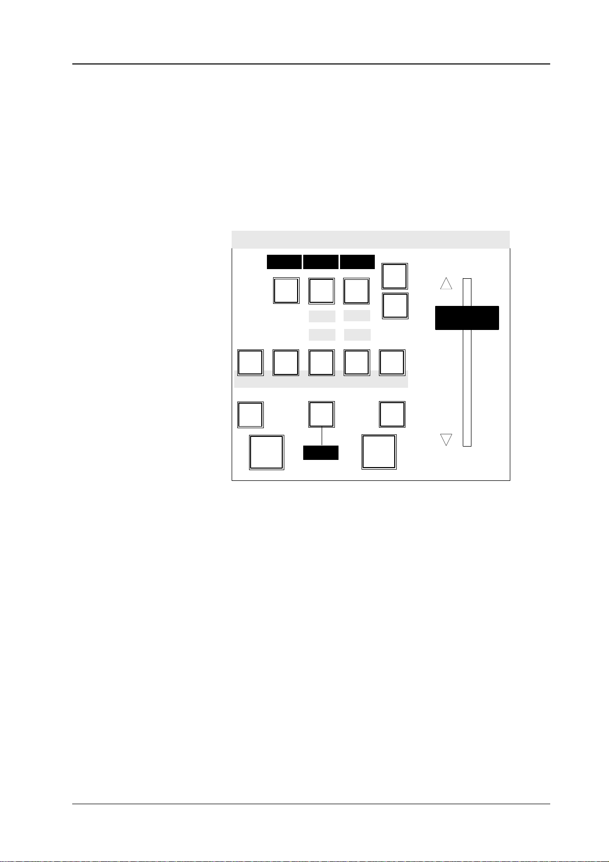
General view of the control panel
Diamond digital DD10
Wipe panel
BTS
Aux Buses
Key Buses
Background
Background preset
Masks panel
Mattes panel
Keyers panel
Masks Positioner
A B C D
A B C D
Transition
MattesKeyersWipe
Stores
Positioner panel
Diamond digital 10
EXTRA
Stores
panel
EXTRA
panel
DSK
Down Stream Keyer
panel and Fade-to-
Source selection panel
Black panel
Transition panel
AUX buses panel
DVE panel
A detailed illustration of the control panel is shown on a fold-out page at the end of the manual.
RPD 10 Control panel
4
Page 11
Diamond digital DD10
2. FUNCTIONAL DESCRIPTION OF THE PANELS
2.1 SOURCE SELECTION PANEL
The
compact switcher Diamond digital DD10 includes 16 serial digital inputs which
can be universally used for video or key signals. The signal of the internal video
store,
a background matte and black as a signal are additionally available.
The
sequence of the 16 inputs is fixed-assigned to the primary keys. Black can be
optionally
The
ers
arranged to the right or left of the key row
key
and fill signals can be optionally coupled (see the sections
Panel
).
2.1 Source Selection Panel
.
Setup
and
Key-
2nd
Key 1
Key 2
Key Buses
Background
Background preset
54321 876
12
BGD
Matte
11109 Black
DSK
On air
On air
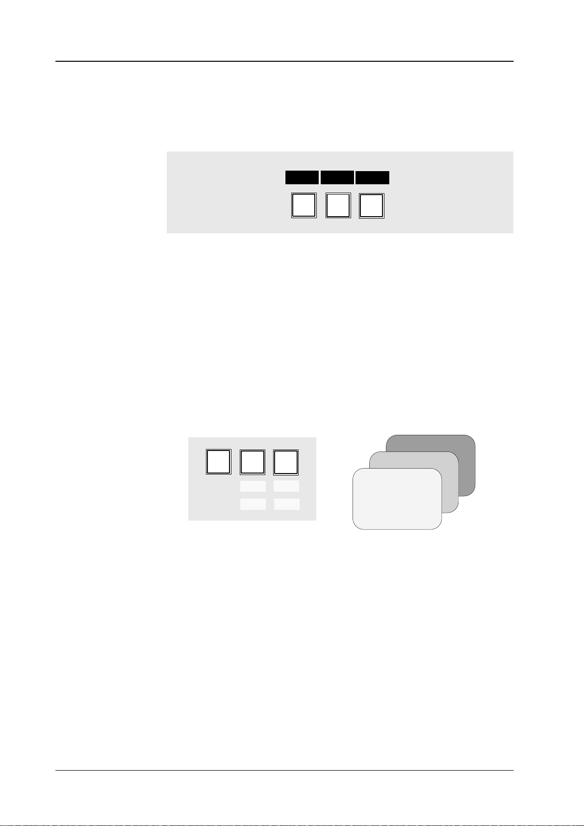
Background The Background bus indicates which current background picture is selected.
Background Preset
Pressing
The
The
involved
tions
Background
another key in this row performs a hard cut to another background
selected background picture can be checked on the program monitor
Preset
bus
serves the preselection and indication of the background picture
in the next transition. The background picture and the selected modifica
(e.g. key) can be previewed on the preset monitor
.
and preset bus operate in the flipflop mode, i.e. after completion of the
running transition, the preset and background sources will change
picture.
.
automatically
Thus, it is clearly shown which signal contributes to the output picture.
The
arrangement of
background and preset bus can be changed from the interna
tional mode (preset bus below) to the German mode (background bus below). See
the
section
Setup.
-
.
-
5
Page 12
2.1 Source Selection Panel
Diamond digital DD10
Key Bus
The Key Bus
is available to all 3 keyers of the switcher. The green displays
for
Assignment
or
by selecting
tion
Details
tion
2nd Delegation The
12 directly selectable sources (e.g. frame store). The 2nd key will light when
pressed.
upper
serves the selection and indication of key and fill signals. The key row
Key 1
ON AIR) and
DSK
show the keyer that the key bus is currently assigned to.
of the key bus is made with
Key 1, Key 2
the keyers with the next transition keys
or
DSK
Key 1
on the Keyers panel
or
Key 2
on the T
panel.
Cut DSK
Key
on
Key
about key control are contained in the
Panel
.
2nd
key enables selection of further signals (e.g. video store) in
Key
1
2
sections
Keyers Panel
addition to the
The currently applicable key assignment is shown by the key caps of the
AUX bus.
, Key 2 (red
ransi-
and
Transi-
On Air
Asynchronous sources
Ext
Aux
Video
16151413
Store
54321
PGMPVWClean
876
Aux1 Aux2 Aux3 DVE
11109 Black
12
The buses involved in the output picture are indicated by the red displays
to
the right of the program and preset bus and by the red displays
DSK
next to the key bus.
Asynchronous picture signals are marked by blinking of the
Input
Corr
BGD
Matte
Video
Store
Key 1, Key 2
On air
display.
2nd
On air
and
Note: Asynchronous picture signals are instantaneously switched through by
the
switcher
always
See also
. An interference-free operation of the succeeding units is
ensured.
REPL ASYNC
in the
CONFIG E BOX
menu.
not
6
Page 13

Diamond digital DD10
2.1 Source Selection Panel
Input Corr
The
switcher is provided with an input correction function which enables individual
adjustments to color and brightness for each input. Thus, for instance, different
scenes
Adjustment:
•
•
•
with dif
Input Corr
Select on the preset bus the desired input and hold the key down.
The marked controls enable changing the following parameters:
BRI Brightness
CON Contrast
SAT Saturation
BAL Balance
ferent light types can be matched to each other
activates the function.
B R I C O N
S A T
= setup
= gain
= color saturation
= Pr-to-Pb relation
B A
L
.
The adjustment can be checked on the preview monitor
• Fast rotation of the control for color saturation beyond minimum saturation,
switches
tion
•
Releasing the source key automatically stores the values.
• The
Modif
The
Input Corr key is also used in copying settings and enabling menus. See the
corresponding
over to monochrome reproduction (color is switched on by fast rota
in opposite direction).
default settings can
Reset
and
sections in this operation manual.
be recalled at any time by simultaneously pressing the
Preset Bus
keys.
.
-
7
Page 14

2.1 Source Selection Panel
Diamond digital DD10
8
Page 15
Diamond digital DD10
2.2 AUX BUSES PANEL
The
compact switcher
puts;
3 of them are designed for video or key signals and 2 for integration of a DVE
unit
with video and key signals.
Diamond digital DD10
includes
2.2
Aux Buses Panel
5 serial digital auxiliary out
-
Ext
Aux
Video
16151413
Store
54321
The Aux Bus
•
all 16 serial picture signals,
•
background matte, BGD Matte
•
picture signal black,
•
picture signal from the internal video store, Video Store
•
the internal signals,
keys
The
ing
state of the aux bus to the respective aux output.
enables selection of the following signals:
Aux 1, Aux 2, Aux 3
PGMPVWClean
876
Black
PVW, Clean Feed
Aux1 Aux2 Aux3 DVE
1..16
and
and
DVE
on the right side assign the current operat
11109 Black
PGM
12
Input
Corr
BGD
Matte
Video
Store
2nd
The other states are internally stored and automatically restored when selecting
another
aux bus.
-
DVE Selecting the DVE bus automatically switches through the associated key signal
via
the DVE key output when the picture signal
(e.g.
caption generator). If no key signal is available, 100% white signal is
at
the DVE key output (see the section
has been coupled with a key signal
DVE Control
).
supplied
If video and key are not coupled, or a signal has to be selected other than the
coupled
•
•
•
key signal, proceed as follows:
Using the DVE key delegate to the DVE bus.
Using a bus key select the video signal.
Hold the DVE key down and select the key signal.
9
Page 16
2.2
Aux Buses Panel
Diamond digital DD10
Ext Aux
Ext Aux enables optional control of 3 buses of an external routing switcher. Depending on the number of keys on the control panel, up to 16 inputs can be selected.
(For installation see the section
Video store Video
Except
See the section
Selection of the routing switcher output rows is made with
Aux 1..3
Setup)
External
Input 1..16
store
assigns the control function of the aux bus to the internal video store.
Routing
Switcher
Ext
Aux 1..3
RS–422
DD10
for the stored picture itself, all signals can be selected.
Stores Panel
.
.
10
Page 17

Diamond digital DD10
2.3 DVE Panel
2.3
DVE P
ANEL
The
DVE mode enables switching the following signals to an external DVE:
•
all signals of the AUX bus
• video
If Loop
signals and – if available –
mixing
stage.
Loop
DVE
Preset
the associated key signal from the respective
BGD
Key
Key
1
2
is not actuated, the respectively selected video signal is switched through
to the DVE. The manipulated signal of the DVE is available on the input routing
switcher
and can be processed in the same way as a normal video signal.
If Loop
manipulated
non-manipulated
is actuated, the respective video and key signal is switched to the DVE. The
signals of the DVE are fed back
signals are switched to. The DVE
to the ME at that place where also the
is looped into the signal or key
path.
PGM
and
Preset
tion
panel
whether the new picture appears with the DVE (preset) or the former pic
disappears with the DVE (PGM).
ture
determine in case of
a background DVE transition on the T
ransi-
When switching the DVE transition on the Transition panel, the functions on the
DVE
panel are automatically switched without delegation.
Note: For DVE integration, the following facts have to be determined in the
Setup
menu:
•
Inputs for video and key signals (activates the function of the
Loop
key)
• Port
assignment for DVE control (activates the function of the Transi-
tion T
ype key)
-
11
Page 18

2.3 DVE Panel
Diamond digital DD10
2.3.1
Connection
Operating modes DVE
NOTES T
O DVE CONTROL
Pleas refer to installation manual.
control
1.
2.
3.
devices that are linked to
can be used in various modes.
FX Loop
In
this mode, the video and key signals to the DVE device are switched automat
ically
and the sequences of the DVE device
Transition
keyers
In this mode, Loop and DVE transition are enabled.
FX Loop without fader
In
this mode, the video and key signals to the DVE device are switched manu
ally. The control of the sequences is made with the DVE digipot in the Wipe
panel,
This
smaller
In this mode, Loop is enabled and DVE transition is disabled.
DVE ef
panel. The DVE device
that are controlled in the same way as wipe transitions.
which in this mode is switched over to DVE operation.
mode permits integrating particularly static DVE ef
pictures at a fixed position.
fects without FX Loop
the Diamond digital switchers in terms of signals and
are controlled with the fader in the
permits transitions of the background and of
fects into a picture, e.g.
-
-
4. In
Effect selection After
with the wipe effect keys in the Wipe panel of the switcher. DD5 and DD10 are
switched
Mask.
The
or,
when the
The DD5
The selectable sequence numbers are as follows:
1. bank 1 - 4 2. bank 6- 9
with the
1. bank 16 - 19 2. bank 21 - 24 3. bank 26 - 29
In this mode, all signals applied to the switcher as well as the internal signals
from
the key levels may
control is made with the DVE digipot in the Wipe panel, which in this mode is
switched
the
In this mode, Loop and DVE transition are disabled.
modes 2 and 3, the DVE
editor
DVE.
Remote has been enabled in the DVE, the desired DVE sequence is selected
wipe keys of a
over to DVE operation. The DVE ef
switcher
Below one of the digipots
2nd
.
instead of the digipot.
over to DVE operation by disabling the functions (keys)
DD20
2nd
key is actuated, to the snapshots 16 - 30.
switcher features less keys for the wipe or sequence selection.
key
be selected as DVE input signals. The DVE sequence
fect
is faded-in at any key level of
device may also be directly controlled by an external
For this no control link exists between switcher and
Wipe1, Wipe2
DVE
is displayed.
switcher correspond to the DVE snapshot numbers 1-15
3. bank 1
1 - 14
or
12
Page 19

Diamond digital DD10
Á
Á
Á
Á
Á
Á
2.3 DVE Panel
Mode 1
ББББББ
FX Loop
ББББББ
ББББББ
If
the
DVE
БББББББББББББББББББББББ
component.
БББББББББББББББББББББББ
the video and key signal is switched to the DVE device for the respective picture
БББББББББББББББББББББББ
component.
Note: In
transition type key is actuated, DVE is selected as transition for a picture
In this case the assigned DVE device is controlled automatically
The Loop mode is enabled automatically
order
to assign the DVE transition mode to a different picture com
ponent,
a different transition type, e.g. Mix or W
.
ipe must be selected
and
for the original picture component. If DVE transition is selected, it is
not
possible to change the transition component as is usual e.g. with
the
Mix or W
ipe transition.
It is particularly important to monitor this particularity when working
with
a DD5 switcher as
ture
component.
If
DVE is
to
permits
used as background transition, it is possible to select whether the signal is
be switched to the DVE from the Background or the Preset bus. This selection
a determination of the type of transition.
Key
Key
Preset
BGD
ON:
* ON:
* With some devices this key is designated
there are no displays above the keys for pic
new picture comes in
old picture goes out
PGM.
If the function (key) Loop is disabled, only the DVE key signal is switched to the
DVE,
not the video signal. This way
without
manipulating the video signal.
, a DVE ef
fect may also be used as wipe ef
fect
-
-
In
this mode 1 (FX Loop), the DVE is only switched into the signal
transition.
Note: It
is possible to deviate from the automatically switched video and
key signals and to switch other signals. However
partly peculiar pictures.
path during the
, this may result in
13
Page 20
2.3 DVE Panel
Á
Á
Á
Á
Á
Á
Á
Á
Á
Á
Á
Á
Á
Á
Á
Á
Á
Á
Diamond digital DD10
Mode 2
ББББББ
FX Loop without
ББББББ
fader
ББББББ
ББББББ
Mode
3
ББББББ
DVE ef
without FX Loop
fects
ББББББ
ББББББ
ББББББ
ББББББ
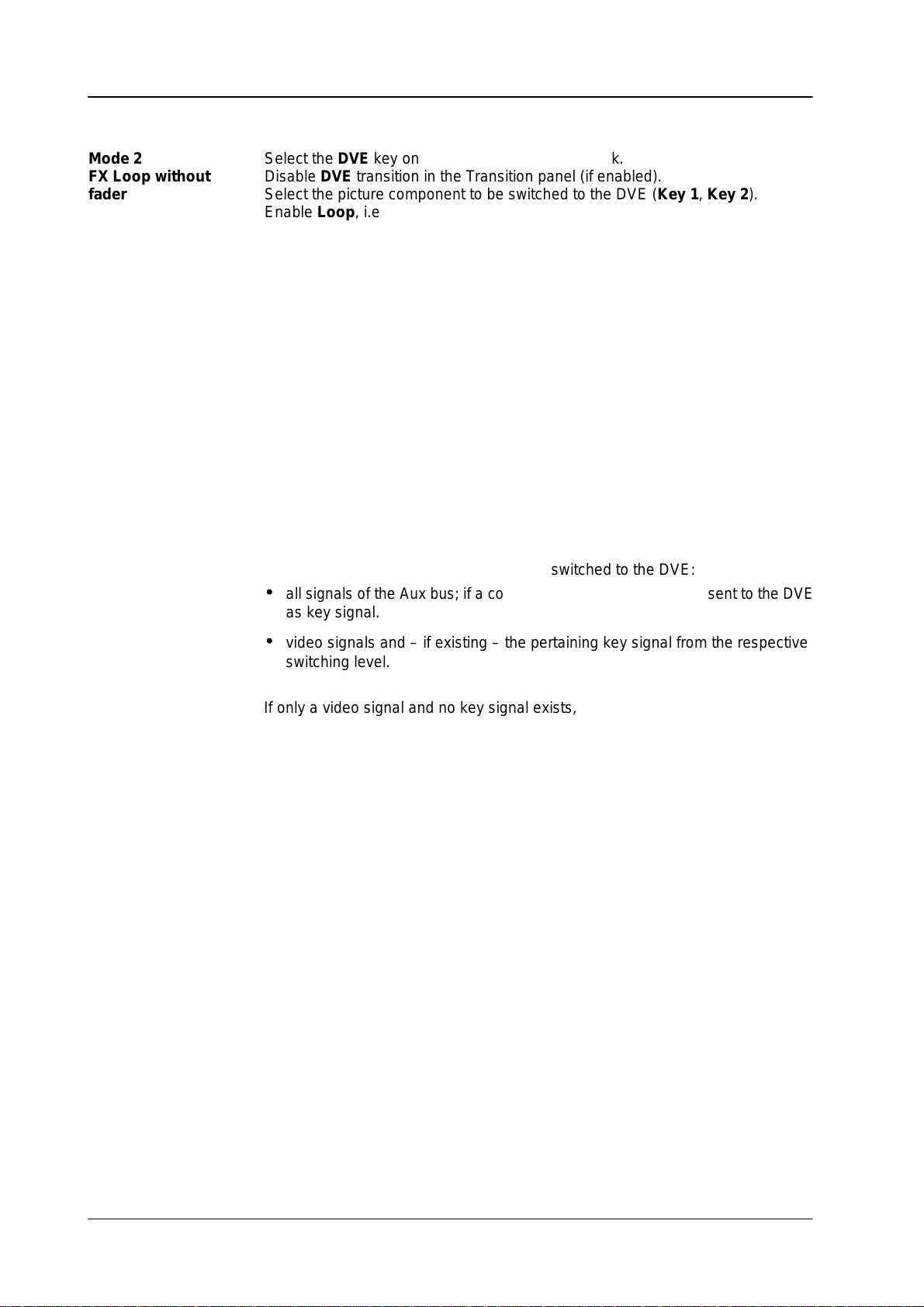
Select the
БББББББББББББББББББББББ
Disable
БББББББББББББББББББББББ
Select the picture component to be switched to the DVE (Key 1, Key 2
БББББББББББББББББББББББ
Enable
БББББББББББББББББББББББ
The DVE
DVE
key on the Aux bus delegation bank.
DVE
transition in the Transition panel (if enabled).
Loop
, i.e. switch DVE into the video path.
digipot in the Wipe panel permits running the DVE
ef
fect. As it is dif
).
ficult
to achieve a continuous sequence with the digipot, this operation can only be
recommended
for a static DVE positioning. A uniform movement can, however
, be
realized with an EXTRA timeline. The picture component manipulated with the
DVE
can be faded with
Note:
Function Loop ON
Function Loop OFF
Select the
БББББББББББББББББББББББ
БББББББББББББББББББББББ
Disable
БББББББББББББББББББББББ
Disable
БББББББББББББББББББББББ
БББББББББББББББББББББББ
In this mode, the following signals can be switched to the DVE:
• all
as
DVE
key on the Aux bus delegation bank.
Loop.
DVE
transition in the Transition panel (if enabled).
signals of the Aux bus; if a coupled key signal exists, this is sent
key signal.
Wipe or Mix
DVE in video path for the picture component
DVE
in the T
ransition panel.
not
in video path for the picture component
to the DVE
•
video signals and – if existing – the pertaining key signal from the respective
switching level.
If
only a video signal and no key signal exists, 100 % white is sent to the DVE as
key signal.
If
the DVE delegation key is held down, any signal may be selected as key signal.
14
Page 21
2.4 TRANSITION PANEL
The
compact switcher
background transition stage and two upstream-keyers being independent of
each
other
The
two keyers enable the operational modes
ally,
the new
Diamond digital DD10
.
DynaChrome function
Transition
WP
1
MIX
BGD
Key Key
1
On
Over Over
2.4 T
ransition PanelDiamond digital DD10
includes a universal mixing stage with
luminance
and
linear key. Option-
provides a brilliant chroma key for both keyers.
WP
2
Limit
set
2
On
Limit
on
Add
BLK
preset
For
picture design, selection can be made between the transition modes
DVE,
and
Wipe, providing up to two wipe generators. The individual picture compo
nents
can be simultaneously faded with dif
Control
of the mixing stage is facilitated by the consequently realized next transition
DVE Mix
Auto
ransition
T
Trans
dur
1 2 3 4
Wipe
Type
Wipe
1
2
Trans
PVW
Cut
ferent transition types.
principle.
In
order to
an
independent preview mixing stage (option).
permit an optimum preview of the picture design, the switcher includes
Add, Mix,
-
15
Page 22
2.4 T
ransition Panel Diamond digital DD10
Next Transition The
components
the keys are mutually exclusive. If several picture components have to be faded
simultaneously,
The
the
The
Wipe2, MIX, DVE, ADD
The
keys.
Key
Priority
The priority among the keyers is indicated by the
If,
for instance, the
Key
levels.
next transition keys
BGD, Key 1, Key 2
enable the user to preselect the picture
which will participate in the next transition. When pressed separately
press the respective keys at the same time.
WP
1
BGD
MIX
Key Key
WP
2
1
2
selected keys light and indicate which picture components are af
next transition. The result can be looked at the preview monitor
displays over the keys indicate which transition type (WP1
) has
been selected for the respective picture component.
current state of a
Over
on the
keyer is indicated by the On display below the next transition
Over
display
Over
Keyers
display below
panel enables the user
Key 1
is lit, keyer 1 is placed over keyer 2.
to change the priority of the key
for Wipe1,
.
fected during
.
WP2
for
,
Background
BGD
Key Key
1
On
2
On
Over Over
Key 2
Key 1
16
Page 23

2.4 T
ransition PanelDiamond digital DD10
Transition Type The Transition Type
In order to select a transition type, activate the next transition key for the picture
component,
Mix,
W
then select a transition type using the transition type keys
ipe 1
, and
Wipe 2
The selected transition type is indicated in the display above the respective next
transition
Note: Please
Add Add
nals.
is
internally limited to aprox. 108%.
key
.
note that you can change the transition type only when the transi
tion
procedure is terminated, i.e. an automatic transition is completed
the
fader is moved to a limit.
provides a transition type which enables addition of the two background sig
In midposition of the fader
panel permits selection of dif
.
Add
DVE
T
ransition
Mix
Wipe1Wipe
Type
, both signals are faded in at 100%. The output level
ferent transition types:
Add, DVE,
2
-
or
-
Note: Please note that this transition type can be only used for background
DVE DVE
same
The
can then be recalled with the wipe selection keys on the Wipe panel when the
associated
Further information and important notes about DVE control are contained in the
section
Note: Please
Mix Mix
nals
transitions.
enables the user to recall DVE ef
way as wipe ef
dif
ferent ef
display shows
DVE Panel
fects.
fects have to be previously programmed on the respective DVE
DVE.
.
fects from the switcher and run them in the
note that transition type DVE can be only effective for one
component.
selects a transition type
which performs cross-fading between the picture sig
selected with the next transition keys.
and
picture
-
17
Page 24

2.4 T
ransition Panel Diamond digital DD10
Wipe 1, Wipe 2 Wipe
generator (1 or 2).
Further
tion
Note: Please note that the wipe generators can be used at the same time for
MultiMix The
transition
Thus,
the
first keyer, W
neously
Adjusting different transition types:
• Select
• Using
• Now
• Pressing
1
and Wipe 2
information
Wipe Panel
different
MultiMix
types for individual picture components and fading them together
for instance,
performed in one transition.
with the next transition keys
and hold the key down.
nent
the keys
tion type. The selected transition type is shown on the display over the next
transition
select in the same way the associated transition type for the other picture
components.
activates
enable a wipe transition with the signal of the respective wipe
on the control of the the wipe generator is contained in the sec
.
applications which may interact with one another
feature provides the switcher with the possibility of selecting dif
Mix
can be selected for the background transition, Wipe 2
ipe 1
for the second keyer
Add, DVE, Mix, W
keys.
the keys
the corresponding picture components for the next transition.
BGD,
Key 1
or
, and all transition types can be simulta
BGD, Key 1
ipe 1
and Wipe 2
Key 2 (or any combination) simultaneously
or
Key 2
, select the desired transi
.
the picture compo
ferent
.
for
-
-
-
-
,
Note: Please
sition
vated.
note that transition type
type
Mix
. Multimix is possible when no T
Add
effects for
Key 1
and
ransition T
Key 2
the tran-
ype key is acti
-
18
Page 25
2.4 T
ransition PanelDiamond digital DD10
Black preset BLK
program
black to the next program event.
preset
event is
Picture A
enables transitions in two steps. During the first transition, the current
faded to black. During the second transition, fade is made from
Black
Picture B
T
ransition can be made with
accentuating this special transition type, BLK preset
For
procedures.
cond
transition.
If BLK preset
tion.
If the function is deselected during fade-to-black, the second transition is
formed
The function is
has been pressed erroneously
immediately thereafter
Cut, Auto
automatically deselected after having finished the se
.
or manually with the fader
is lit during the transition
, actuate it again to deselect the func
.
per
-
-
-
19
Page 26

2.4 T
ransition Panel Diamond digital DD10
Fader The
fader
view
Cut Cut
Auto Auto
light
associated
The
ished
In the same way, it is possible to halt the automatic transition by pressing Auto
again
fader enables sensitive manual transitions. The yellow arrows to the left of
show the moving direction to
monitor
causes an instantaneous transition (hard cut).
performs the transition as a fade with the preset transition rate. The key will
for the duration of
transition can be immediately completed by pressing
with the fader
and to continue by pressing it once more.
.
display
the transition and the selected transition rate is shown in the
.
.
the next contribution which is shown on the pre
Cut
or be manually fin
the
-
-
T
rans dur
Key 1, Key 2 If
The
function Trans dur
9999
frames.
Adjustment:
• Press
•
•
• If
the keyers have to be switched on or of
select
perform
Trans dur
keypad
Enter the desired transition rate with the numeric keypad.
For checking, the entry is shown in the display
Faulty entries can be deleted by pressing
After entry
tion.
on the EXTRA panel will light and request entry of the rate.
, press
Trans dur
the corresponding key stages with
a hard cut with
has been erroneously pressed, press it
ation enables selection of a transition duration within 1 and
. After actuation, Trans dur
Enter.
f without using the next transition function,
Key 1
Cut
on the
Keyers
and and the keys of the numeric
.
Clr.
or
Key 2
panel.
again to deselect the func
on the
Keyers
panel and
-
20
Page 27

Trans
PVW
2.4 T
ransition PanelDiamond digital DD10
Trans PVW enables the user to optionally perform the transition on the preview
monitor
Trans
matically
Now it is possible to select other transition modes, deselect picture components
and
without af
PVW
restored when leaving the T
perform the transitions with
fecting the output picture.
will light when actuated.
All current adjustments are stored and auto
ransition PVW mode.
Cut, Auto
or manually with the fader
.
-
Note: Please
only when the transition is finished, i.e. an automatic transition is completed
If
is required to transmit another background picture to the output while Trans PVW
is
activated, this can be
the On air
At
end of transitionwith TRANS PREVIEW on, the PGM and PST Bus do not longer
switch.
Operation
New setting
“Mode 1” =
“Mode 2” =
“Mode 3” =
note that
or the fader is moved to a limit.
display
of TRANS PVW can be modified in menu CONFIG. P
. Then a hard cut is made to the other background picture.
TRW-PVW
compatible operation.
TRANS PVW stays on and shows in endposition the final image
on
the PVW output.
TRANS PVW goes automatically to the begin of the transition
whenreaching the endposition.
Does not apply with LIMIT ON.
“One shot mode”.
TRANS PVW switches automatically of
either endposition.
Note: Also when returning to the begin TRANS PVW is switched
off.
Does not apply with LIMIT ON.
the T
rans PVW mode can be activated and deactivated
made by direct selection on that bus which is indicated by
ANEL.
f, when T
-Bar goes to
Note:
Lim set, Lim on Limit
mode
Limit set
Limit
with
If
the transition is performed with the fader
does not
that
If
the
transition
path
Mode 2 and 3 behave as described when using the T
controlling the transition. AUT
equivalent to Mode 1.
set
and
Limit on
is possible for all transition types.
stores the desired value which has been adjusted with the fader
on
switches the mode on. A transition with
the fader is only made up to the value previously defined with
change the
the transition is not completed.
Limit on
is then transferred to the full fader path.
mode is then switched of
can be made with the fader to the next contribution. The remaining
serve the reproducible generation of partial transitions. The
direction when the fader is moved to a limit, thus indicating
f at the point defined by
O transition behaves as before
Cut, Auto
, the yellow arrow to the left
or a manual
Limit set
-Bar for
.
transition
Limit set
of the fader
, a jerk-free
fader
.
21
Page 28

2.4 T
ransition Panel Diamond digital DD10
22
Page 29
Diamond digital DD10
2.5 DOWNSTREAM KEYER PANEL
The
compact switcher
enables
key
the
the user to
into the program picture.
insert captions, numbers or characters by
background and all other keyers.
2.5 Downstream Keyer Panel
Diamond digital DD10
includes a
downstream keyer
luminance or
This keying has priority so that it appears in front of
Background
Key 1
Key 2
DSK
which
linear
Beside the main outputs, the switcher additionally includes a clean-feed output
which
input sources as well as the signal of the internal video store can be used as a
All
key
For
Cut Cut
Auto Auto
The key will light for the duration of the transition and the selected transition rate
is shown in the display. Pressing the Cut key completes the transition instanta-
neously.
If
the automatic transition has been started erroneously
celled
provides the picture in front of the downstream keyer
.
source. For filling, also all input sources or an internal matte are available.
control, see the sections
Source Selection, Keyers Panel
and Mattes Panel
DSK
Cut
Auto
performs the transition as a hard cut.
performs a transition with the preset transition rate.
by pressing the Auto key again.
Trans
dur
1 2 3 4
FTB
DSK
On
, it can be stopped and
can
.
-
Keying-in with DSK is indicated by the
DSK On
display
.
23
Page 30

2.5 Downstream Keyer Panel
T
rans dur
The
and
Adjustment:
function Trans dur
9999 frames.
ation enables
Diamond digital DD10
selection of a transition duration between 1
• Press
•
•
• If
Trans dur
on the EXTRA panel will light and request entry of the rate.
pad
Enter the desired transition rate with the numeric keypad.
For
checking, the entry is shown in the display
pressing Clr.
After entry
Trans dur
tion.
. After actuation, Trans dur
, press
Enter.
has been pressed erroneously
and the keys of the numeric key
. Faulty entries can be deleted by
, press it
-
again to deselect the func-
24
Page 31

Diamond digital DD10
2.6 FADE-TO-BLACK PANEL
The
compact switcher
allows
fading the program picture to or from black.
Diamond digital DD10
DSK
includes a
2.6 Fade-to-Black Panel
fade-to-black
stage
which
Cut
Auto
Trans
dur
1 2 3 4
FTB
DSK
On
FTB FTB switches the panel from downstream keyer control to fade-to-black control.
The
operational mode is indicated by lighting-up of FTB
. When switching over
, all
settings of the Downstream Keyer panel are stored and automatically restored
when returning to the DSK mode. If FTB has been pressed erroneously, press it
again
to deselect the function.
Cut Pressing Cut performs the transition as a hard cut. For accentuating this special
operational state, FTB will blink during the fade-out state. Pressing the blinking
FTB
key
fades the program event in again and subsequently disables the fade-to-
black
function.
Auto Pressing Auto
light
during the duration
display.
be
If an
stopped and cancelled by pressing
performs the transition with the preset
transition rate. The key will
of the transition and the transition rate is indicated in the
automatic transition has been started erroneously
Auto or FTB
again.
, the procedure can
For accentuating this special operational state, FTB will light during the fade-out
state. Pressing the blinking FTB key again fades in the program event with the
same
transition rate and subsequently disables the fade-to-black function.
Note: Should it be required to switch the downstream keyer on or off during
fade-to-black,
ers
panel and perform a hard cut with the
select the downstream keyer with the
Cut
key
.
DSK
key on the Key
25
-
Page 32

2.6 Fade-to-Black Panel
T
rans dur
The T
rans dur
black
between 1 and 9999 frames.
Adjustment:
ation function enables selection of a transition duration for fade-to-
Diamond digital DD10
• Press
•
•
• If
Trans dur
on the EXTRA panel will light and request entry of the rate.
pad
Enter the desired transition duration with the numeric keypad.
For
checking, the entry is shown in the display
pressing Clr.
After entry
Trans dur
tion.
. After actuation, Trans dur
, press
Enter.
has been pressed erroneously
and the keys of the numeric key
. Faulty entries can be deleted by
, press it
again to deselect the func-
-
26
Page 33

Diamond digital DD10
2.7 KEYERS
2.7 Keyers
Keyers
Bord
Key
over
Matte
Add
Lin––
Auto
Cut
Bord
off
Key
inv
Key
Bus
Fill Source
Lum
––Lin
Type
Cursor
Key
on
Shdw
Border
Mask
on
Split
Key
Chr
Key
Key
1
Key
color
Drop
Mask
Key
Key
Bus
Pattn
Key
Out
line
Key
PVW
Coupl
Split
Pattn
1
2
2
Source
Selectivity L
Luminance Hue
DSK
Position
Opacity
Gain/Size
Density
Selectivity R
Opacity
FGD
fade
Clip
Clean up
Selectivity
Chroma
Y
27
Page 34

2.7 Keyers
Diamond digital DD10
2.7.1
2.7.2
KEYER DELEGA
TION
The
delegation keys
to one of the three
has
to be changed.
I
fthe function
menu
when the key types
This delegation also delegates the key bus.
HARD KEY TRANSITION
Key 1, Key 2
keyers
Auto Menu
Cut
and
DSK
enable delegation of the Keyers panel
when the keyer proposed by the auto delegation system
is activated, the delegation keys switched on the keyers
Add, Lum, ChrKey
Key
on
Key
1
are slected.
Key
DSK
2
Cut
causes an instantaneous transition (hard cut). When a keyer is
will
be indicated by the
Key on
display
.
faded in, this
28
Page 35

Diamond digital DD10
2.7 Keyers
2.7.3
KEY MODES
Mask
Key
Add
Lin––
Lum
––Lin
Type
Chr
Key
Pattn Pattn
1
2
Source
Note The Add Lin and Lum Lin keys enable selecting three operational
modes
(see below).
The keys are lit as follows:
Key function
additive key
multiplicative key
Add/Lin (Lin Key)
YES NO
YES YES
Lum/Lin (Lum Key)
gain = unity
multiplicative key
NO YES
gain <> unity
Add Key
Add
Key
selects the
modern
and
caption generators, paint
the associated fill signal.
Additive key mode. In this mode, an external unit (e.g. DVE,
systems) generates and supplies the key signal
The background signal is multiplied with the key control signal and added to the
supplied
and
fill signal. This mode ensures that the supplied fill signal is not influenced
all data contained therein will be played back in accordance with the
original.
Note: Please note that the supplied fill signal must be based on a black
background.
ored
background signal.
Otherwise
the addition of the signals will yield a discol
-
29
Page 36

2.7 Keyers
Diamond digital DD10
Lum Key
Lin Key
Lum
Key
selects the luminance key mode. The key control signal is derived from
the
luminance component of the key source signal. The key control signal controls
the
transition between background signal and fill signal.
Luminance Key is available in the modes equalized (eq) and non-equalized.
Lum Key eq
Lum
Key
Note:
Pressing
mode.
nance
On American linear key
the two keys (Add) Lin and (Lum) Lin sets the luminance key into a linear
The key control signal corresponds to the non- amplified and unlimited lumi
signal.
Is automatically switched on in the Self Key mode
(key fill signal corresponds to the key source signal).
Thus,
dark halo ef
avoided.
Is
automatically switched on when Fill and
have
the same source (Non Self Key).
.
fects at
edges and soft transitions are
Source do not
-
Chr Key
FGD Fade
Pattn 1, Pattn 2
Chr
Key
selects the chroma key mode. The key control
chrominance
The
DynaChrome Key
ved
in accordance with the original.
Note:
When
the Foreground Fade function is enabled, the key
fade
between the background signal and the cleaned key fill signal.
Note: Please note that DynaChrome can only be used without Foreground
Pattn 1
pattern
of
the pattern can be adjusted with the
Positioning
this
purpose, previously press
component of the key source signal. Keying is possible on each
mode ensures that all details in the fill signal will be preser
Please note that P/S/S = ON forcibly switches over to FGD–Fade.
Fade
for Self Key (identical fill and source signal). If you are not working
with
Self Key or in case of a border
be
switched on without special indication.
or Pattn 2
can be selected with the pattern selection keys on the Wipe panel. The size
of the pattern is possible with the trackball on the Positioner panel. For
selects the wipe generator as a key source (pattern key). The
Pos
on the Wipe panel.
, Foreground
Size
control.
signal is derived from the
color
in control signal serves to
Fade will automatically
.
-
30
Note: Please note that the wipe generators can be used at the same time for
different
applications which may interact with one another
.
Page 37

Diamond digital DD10
2.7 Keyers
Mask Key Mask Key
See the sections Mask Panel, W
Note: If the function KEY MEMORY is activated (menu CONFIG EBOX) the
selects the mask chosen on the Masks panel, as a key signal.
ipe Panel and Stores Panel
operation modes Mask key and Pattern key can be switched off by a
renewed
Then the mixer take up the status (see Key Memory) of the last stored
“natural”
If
the operation modes
direct
mer
pressing of the corresponding key
key (
Add, Lin, Lum or
Mask key
selection of the key modes
settings are only available partly
Chroma key
and
Add, Lin, Lum
.
) with all settings.
Pattern key
.
.
are switched off by a
or
Chroma key
, the for
-
31
Page 38

2.7 Keyers
Diamond digital DD10
2.7.4
Key Fill
KEY SOURCES
The mutually exclusive keys
a
signal from the key bus or a matte as
can
be adjusted on the Mattes panel.
Matte Matte
be
adjusted on the Mattes panel.
Key Bus
Key Bus
When
and
filling.
Matte
Key Key
Bus Bus
Fill Source
Key
Split
Key
Bus
(on the left) and
a fill signal for the respective key
Coupl
Split
Matte
enable selection of
. The matte
on the Fill panel enables selection of a matte as a fill signal. The matte can
(on the right) directly selects the key and fill sources on the key bus.
the key is lit, the key bus indicates the source which can be used for keying
Couple/Split Couple/Split
When
the key is lit, the coupled key source signal is selected in addition to the se
lected key fill signal. Without coupling, the key fill signal corresponds to the key
source
signal (self
For selecting any key source, proceed as follows:
D
Press
Couple/Split
D
Now select on the key bus the new key source.
D After
The
the
If
separation of key source and fill signal has to be cancelled, just press
Note:
releasing the keys, the state is shown by the
bus
indicates again the fill source.
key source signal
key bus.
If you want to see
as a key source, press the Couple/Split key. The key bus indicates the
source
derives the key
source from a dif
key).
and hold it down.
is now determined. The key fill signal can be switched with
in
the split key mode which source you have selected
as long as the key is pressed.
ferent signal than that of the key bus.
-
Split Key
display
. The key
Key Bus
.
32
Page 39

Diamond digital DD10
2.7 Keyers
2.7.5
KEY ADJUSTMENTS
Keyers
Bord
off
Key
over
Matte
Add
Lin––
Auto
Bord
Key
inv
Key
Bus
Fill Source
Lum
––Lin
Type
Cursor
Shdw
Border
Mask
on
Split
Key
Chr
Key
Key
color
Drop
Mask
Key
Key
Bus
Pattn
Out
line
PVW
Coupl
Split
Pattn
1
Source
Selectivity L
Luminance Hue
Key
2
Position
Opacity
Gain/Size
Density
Selectivity R
Opacity
FGD
fade
Clip
Clean up
Chroma
Border
Position, Opacity
Opacity
Gain/Size
Density
Clip
Clean up
Cut
Key
on
See the section
The Opacity
The
Add, Luminance or Chroma Key modes enable to optionally adjust the steep
Key
Key Borderliner
control adjusts the transparency of the key
ness (gain) of the key control signal or the density of the foreground signal. Selec
tion
is made in the Key menu.
The
Add,
Luminance or Chroma Key modes enable to optionally adjust the clipping
Key
1
DSK
2
.
.
-
-
point of the key control signal or the cleanness of the background (noise, undesired
shadows,
uncleanness).
33
Page 40

2.7 Keyers
Diamond digital DD10
2.7.6 AUT
2.7.7
Chr Key
CHROMA KEY
O KEY ADJUSTMENT
Auto
key ef
Add
Key
switches the key control to 1:1
from
the caption generator have an unchanged ef
Luminance
ched
through.
For
Chroma Key
Note: After
rameters
Press Chr Key in the Keyers panel to select Chroma Key mode. In DynaChrome
Key
mode, the foreground signal is proportionally
key color in the key color area and colored neighbouring areas. The result is a
cleaned
in
The
signal
multiplied background signal are added. This method ensures that all details are
reproduced
key fill signal which now contains
neigh-bouring areas the de-mixed foreground colors.
key control
is multiplied with the background signal. The cleaned key fill signal and the
fects dif
Key
true to the original in the area of the key color
ferent automatic functions in the dif
transmission in order that key signals. e.g.
adjusts Clip and Gain in such a way that the key signal is just swit
see the section
termination of all automatic key adjustments, the corresponding pa
can still be changes manually
signal is also derived from the foreground signal. The key control
Automatic Chroma Key Adjustment.
and subtractively deprived by the
in key color areas shadow-free black and
ferent key modes.
fect.
.
.
-
-
FGD Fade
The FGD Fade (foreground fade) key switches over the chroma key procedure.
Now,
the cleaned key fill signal and the background signal are faded in one fading
operation
is
subtractively removed, luminance is retained. However
vantages
rency).
For optimal adaptation of cross fadings on edges or for optimization in case of
transparencies
adjusted
Adjustment is made with the Luminance control. During adjustment, Key color
has
This mode is recommendable when object edges will show unnatural, extreme
brightenings
adjustment,
For optimal adaptation of fade transitions at edges or for optimization in case of
transparencies
adjusted in the area
tion LUMOFS (Luminance Offset). During adjustment, the Key Color key has to
be
held down and the
by the key control signal.In the area of the key color
of
the DynaChrom procedure (good reproduction of details and transpa
between foreground and background,
in the area of the key color
to be held down.
in details and transparency areas in case of too intense CLEAN–UP
or extreme darkenings in case of too intense DENSITY adjustment.
between foreground and background,
of the key color transitions. Adjustment is made with the func
Luminance
.
control be operated.
, only chrominance
, this will impair some ad
the luminance value can be
the luminance value can be
-
-
-
34
Page 41

Diamond digital DD10
2.7 Keyers
Note: Please note that Foreground Fade is enabled automatically – without
special
• Chroma
• Chroma
• not
indication – in the following modes:
Key Invert
Key with Border
Self Key
.
Before
on the picture source side to ensure low interference, for example by an
evenly
adjusting Chroma Key, you should try to create optimum conditions
lit blue wall of maximum size and little camera post-amplification.
35
Page 42

2.7 Keyers
Diamond digital DD10
2.7.7.1
Auto
Cursor
Automatic Chroma Key Adjustment
This mode serves to adjust the following parameters:
• key
color for LUMINANCE, HUE and CHROMA
• selectivity
The
parameters
by
the adjustment to max. ccw position (inef
SELECTIVITY is set to center position (i.e. inef
COLOR CAN and NOISE REDuction to ON, P/S/S and SEL MASK to OFF
Pressing the
The
picture evaluation includes all
+/–30o around the primary color Blue. Within this range, blue with the highest
sity
is detected as key color
Pressing the
When
you press the key
the preview monitor
in
the Positioner panel.
Then press the Auto key to start the adjustment. Only those colors will be evaluated
the color angle of which resembles to that which was found within the cursor
With
the condition of this color angle the complete picture
with
the highest intensity is detected as a key color
for SELECTIVITY LEFT and SELECTIVITY RIGHT
DENSITY
Auto
key starts an automatic key adjustment to
Cursor
. Move the cursor to a spot of the key color using
, CLEAN UP and SELECTIVITY
fective).
fective).
those colors which are within an angle range of
. Key color and selectivity are thus adjusted.
key starts an automatic, cursor–assisted key adjustment.
, the key fill signal with key color and a cursor appears on
-CENT are set by default
Blue.
the
is evaluated and the color
.
.
inten
trackball
-
.
Note: The Auto keys in the Chroma Keyer and the Keyers panels operate in
parallel.
When
matic
2.7.7.2
Selectivity Selectivity L (left), Selectivity R (right) and Selectivity Y enables the user to
Manual Optimization in case of critical patterns
change
This may be required for the following reasons:
• The user wants another compromise between color fringe and density of the
•
•
•
The
ponent.
the
the selectivity manually
foreground
Size and sharpness of the foreground object were not suf
Blue spill has to be removed from the foreground object.
The picture only contained the key color and no foreground object.
selectivity separates the unchanged
The attributes
chromatic circle. Y refers to the luminance dependence
the Keyer is on,
adjustment.
object.
Left
and Right refer to the neighborhood to the key color in
the output signal will be affected during the auto
.
ficient.
colors from those without key color com
of the gray mixed color
-
.
36
Page 43

Diamond digital DD10
Thus,
the key color Blue influences the following colors:
•
by
Selectivity L,
•
by
Selectivity R,
•
by
Selectivity Y, the gray/yellow colors.
Direction of rotation of the controls:
the reddish neighboring colors
the greenish neighboring colors
2.7 Keyers
Selectivity C
influence of the foreground is increased when
The
Selectivity R is turned right.
When Selectivity L
high
selectivity (i. e. narrow band color selection) is set.
With Selectivity Y = 50% (center position after automatic run), this parameter is
without
creasingly by the key color
low
yellow
Adjustment of the selectivity should be just so
the foreground object has disappeared. Doing so, a slight ”keying” of the foreground
(
Selectivity
slightly
Problem:
Solution:
influence
(blond) hair becomes yellow (blond) again when its gray was ef
and blue key colors.
object may be first put up with.
Key Color
key +
center refers to the achromatic center of the color circle and acts on the
saturated key colors which cannot be influenced with SEL_R.
The light blue shirt of a newscaster is slightly transparent after adjustment. It could be made dense with DENSITY
lose its blue color
Rotate
Then
is at the right
on the picture. Higher values (cw rotating) deprive gray edges in
, thus coloring them complementarily
Density
correct possibly obtained blue fringes with SEL–L and SEL–R.
knob)
Selectivity C
stop and
.
in cw direction until the shirt is dense.
Selectivity R
Selectivity L
is at the left stop, a very
much that the key color portion on
is turned left and
. A gray halo in yel
fected by mixing
; however it would
-
-
Density
Clean up
Alternative: For
The
Density
This may become necessary if the foreground object is slightly ”keyed” (trans parent) as a result of blue spill and/or the required selectivity setting.
The Clean up
This
may become necessary if the background contains noise or undesired shad
ows
etc.
The
setting first acts on the brightest key color areas. The interference will deterio
rate
for darker colors that remain uncleaned.
reducing newly occurring blue fringes, first use DENSITY and
then SELECTIVITY C as described above.
control can be used to restore the density of the foreground object.
control can be used to ”clean up” the background.
-
-
37
Page 44

2.7 Keyers
Diamond digital DD10
2.7.7.3
Key Color
Manual Adjustment of the Key Color
Press and hold Key Color to permit a manual adjustment of the key color, i.e.
access
The following conditions must be given:
to the parameters of
luminance, hue
and
chroma.
• FGD Fade ”OFF”
• Key
”ON” on background Black
• Density,
• Selectivity L
• Selectivity
• Luminance
• Chrominance
The adjustment is made in the following order:
Hue Turn
Selectivity
Chroma Turn the Chroma control until also the brightest color is remains only just achro-
matic.
Clean up
R
at left stop
the
Hue
control until
roughly until approximately all key colors are covered.
and
at right stop
at left stop
at
left
right
the key color is extensively achromatic. Then turn back
Selectivity C
stop
at left stop
Luminance Turn
This setting can subsequently be optimized with the Selectivity, Density and
Clean up
2.7.8
2.7.9 KEY
KEY PRIORITY
MASKING
Key
indicated on the Transition panel by the Over display beneath the next transition
keys
If,
for instance, the
The mask selected on the Masks panel is switched on with the
See the sections
the
Lumincance
controls.
Over
interchanges the priority of the keyers. The priority among the keyers is
Key 1
and
control until the key color is only just black.
Key 2
.
Over
display lights below
Masks Panel
and
Stores Panel
Key 1
, keyer 1 is placed over keyer 2.
.
Mask on
key
.
38
Page 45

Diamond digital DD10
2.7 Keyers
2.7.10
2.7.11
KEY PREVIEW
KEY INVERTING
Key PVW displays the keyer result or the key signal on the preview monitor for
being
optimized.
The
function enables the user to adjust a keyer
panel.
tion
Pressing Key PVW
preview
•
•
Key inv inverts the key signal, i.e. the contents of the foreground and the background
monitor:
Original key fill signal on current background picture.
Key control signal as black/white signal.
are exchanged on the screen.
repeatedly
, successively switches the following signals to the
which is not selected on the T
ransi-
2.7.12
COPYING KEY SETTINGS
The
adjustments of a keyer can be easily
This
requires the following steps:
•
Press
• Select with the delegation keys Key 1, Key 2 or DSK the keyer you want to
copy.
• Using
another delegation key
justments
Input Corr
to.
copied and assigned to the other keyers.
(on the Aux Bus panel); the key lamp lights.
, select the destination you want to copy the
ad-
39
Page 46

2.7 Keyers
Diamond digital DD10
2.7.13
KEY BORDERLINER
The Border key group enables the user to provide the key signals with a border
which can be adjusted individually
effect
Note:
Border of
f
Border off
Border Border
width of the borderline (number of picture lines: H and 2H). After having pressed
the
key for the third time, the function is disabled again.
Bord
off
Bord
Shdw
Border
Drop
Out
line
Position
Opacity
.
Please note that two borderliners are provided for the three keyers.
switches the border functions of
generates a simple borderline. Pressing the
f.
key several times changes the
Shadow Shadow produces a shadow at the right side and bottom of the key area. Pressing
the key several times changes the width of the shadow (number of picture lines:
H, 2H, 3H and 4H). After having pressed the key for the fifth time, the function is
disabled
again.
Drop Drop adds a drop shadow to the right side and bottom of the key area. Pressing
the key several times changes the width of the drop shadow (number of picture
lines:
H, 2H, 3H and 4H). After having pressed the key for
is
disabled again.
the fifth time, the function
Outline Outline produces a simple outline shape of the key source. The outline signal is
filled
with the background signal. Pressing the key several times changes the width
of
the outline (number of picture lines: H and 2H). After having pressed the key for
the
third time, the function is disabled again.
Position The Position control changes the position of the border in steps.
Note: Please note that the position of the original signal changes when you
want
to position a shadow above or before the border signal.
Opacity The Opacity control changes the transparency of the border
40
.
Page 47

Diamond digital DD10
2.7 Keyers
Border off
Border
Drop
Background
Key
Shadow
Outline
41
Page 48

2.7 Keyers
Diamond digital DD10
2.7.14
NOTES T
O THE USE OF ADD AND LUMINANCE KEY
The operational modes Add and Luminance Key differ in the fading procedure.
In
the Luminance key mode,
mode,
the background is faded and the foreground is added to the background.
Luminance Key
Add Key
foreground and background are faded. In the add key
K
Key
Fill
Out
BGND
1 – K
1
Key Fill
Out
BGND
1 – K
When should Add Key be used?
Add
key can always be used when the pattern (caption etc.) is available on a black
background or in the Split/Coupled Key mode, a separate key signal is available
which
matches to the pattern (caption generator etc.) with regard to contour
Since
only the background is faded out at the place of the key signal with the exact
edge
shape and the foreground signal is
gnals
fit
without error into each other in the transition area. Precondition is that the
key signal is processed with
gain
factor 1 which is achieved by actuating the
key with Add Key or max. ccw position of the
added to the faded background, both si
Gain
control. Under the above-men
.
Auto
tioned conditions, this key type leads to the best results and it should be aspired
to
adequately prepare the key sources (e.g. captions on black background etc.).
Key Signal
Fill Signal
Faded Background
BGD x (1–Key Signal)
Fill-Signal
+[BGD x (1–Key)]
-
-
42
Page 49

Diamond digital DD10
2.7 Keyers
When should
Luminance
a
black background. A
Key mode when the key signal does not match with the fill signal with regard to
contour
A
tuating the keys
luminance value range is completely and ”linearly” reproduced on key
range,
Actuating
reproduced
from that, the found adjustment can at any time be manually optimized by Clip/
Gain or
The
Key
luated
ly equalized. Thus is ensured that no dark edges are obtained at bright objects. Un
proportional darkenings with plane luminance intermediates are not obtained
neither.
When,
Lin and Auto, a relatively dark luminance level is declared to be the foreground
level,
(e.g. DVE key signals with soft border).
so-called ”linear luminance key” (Lin Key) can be selected
regardless whether these extreme values also occur in the picture.
new
that in the Self Key
levels are obtained. Now
however
this will of course also be reproduced, with the ef
Luminance Key be used?
Key has
the
on KEY=0 and the momentarily
Clean up/Density
key processor II
always to be used when the key fill signal is not available on
further application for Luminance Key is in the Coupled/Split
Add/Lin
Auto
, by adjustment of
and
Lum/Lin
key achieves that the momentarily darkest luminance value is
.
overcomes the traditional disadvantage of the Luminance
mode, square-distorted edge shapes or erroneously eva
, a fill signal is generated which has been complete
Clip
by simultaneously ac
, thus achieving
brightest value on KEY=1. Deviating
and
Density
that
the maximally possible
, deviating from adjustment of
fect of fresh dark edges.
signal
-
value
-
-
-
43
Page 50

2.7 Keyers
Diamond digital DD10
44
Page 51

Diamond digital DD10
2.8 OPERATION OF THE KEYER MENUS
2.8 Operation of the keyer menus
2.8.1 SELECTION
Status menu Diamond digital DD10
OF THE KEYER MENUS
The
menus of the
If
the
Auto Menu
pressing
keyer are selected from the Status menu of the respective mixer
function is activated in the Installation menu of the control panel,
a key in the Keyers panel also switches to the associated keyer menu.
.
Status menu Diamond digital DD20 / DD30
45
Page 52

2.8 Operation of the keyer menus
Diamond digital DD10
2.8.2
2.8.3
SELECTION OF THE KEYER ON DD10
For selecting the different keyers, the menu provides a cursor–sensitive switch
area. Touching this switch area cyclically calls the next keyer in the menu. If the
Auto
Menu
function is activated, pressing a key in the Keyers panels also switches
to the associated menu when one of the key types
selected.
is
SELECTION OF THE KEYER ON DD20 / DD30
Add, Lum, Lin, Lum
or ChrKey
VTR
Enbl
ME1
ME2
PP
Edit
Enbl
Status
EXTRA
Access
Mont
Proc
Stores
The
Keyer key of the menu selection key block serves to select the dif
in
the menu. Repeated pressing cyclically calles the menus.
GPI
Enbl
Transf
GPI
Key
Install
Masks
1
2
ferent keyers
3
4
Exit
Exit
46
Page 53

Diamond digital DD10
2.8 Operation of the keyer menus
2.8.4
POSITIONING SIZING SOFTENING P/S/S
These
three functions are available in the
in
the DynaChrome.
Lum/Add key
and
FG Fade
modes,
not
Positioning
Sizing
Softening
Attention:
All
P/S/S parameters are stored in the KEY MEMORY, independent of the key type.
With RESET
justment
The
setting range amounts to +/ – 8 pixels with a smallest increment of 1/8 subpixel.
A
positive Positioning shifts the key signal with regard to the fill signal to the right.
The
setting range amounts to +/ –
with
all permitted key types. A positive sizing extends the key signal, thus reducing
the foreground objects. By this way
ever,
foreground details will also disappear more and more.
A negative sizing increases the foreground object around the object edges. Dark
or key-colored object edges are added.
The
key signal is
are
softened.
When
selecting P/S/S in the
cedure automatically switches to FG Fade (quality loss)! When selecting
P/S/S in the
matically
, all P/S/S
(AKA), all P/S/S parameters are switched to
ommitted for the luminance key procedure (quality loss)!
parameters are reset. When starting an automatic key ad
filtered with an adjustability of 10 steps. Object edges and details
Lum Self Key
8 pixels with a smallest increment of 1/4 subpixel
DynaChrome
mode,
, incorrect object edges can be removed. How
mode, the chromakey
the fill linearization is auto
OFF
, but will be preserved.
pro
-
-
-
-
47
Page 54

2.8 Operation of the keyer menus
Diamond digital DD10
2.8.5
CLEANUP / DENSITY UND CLIP / GAIN
Each
key type provides the possibility of processing the key signal according to this
method
depending
however, should be made prior to the adjustment procedure – subsequent switching
or that one. Each imaginable result can be obtained by both methods, but
on the purpose, this method or that one succeeds faster
will af
fect the result.
. The selection,
Cleanup / Density
Both
methods enhance the characteristic curve of the key signal. The only dif
ence is the invariant center of rotation of the characteristic curve.
Each automatic run resets all four parameters.
This
method influences only one end of the key area and keeps the other one invari
ant.
CLEANUP
influences only the area of the background. Key levels are
increasingly limited to black, i.e. ”cleaned”. Noise and
slight shadows in this area will disappear
.
fer-
-
48
DENSITY
influences only the area of the foreground. Key levels are
increasingly limited to white to the unity value ”1”, which
corresponds to the ”dense” foreground.
Page 55

Diamond digital DD10
Clip / Gain
2.8 Operation of the keyer menus
This
method influences both ends of the key area and leaves only one selectable,
average
clip value invariant.
CLIP
GAIN determines
determines that key signal level in the proximity of which linear
unlimited
CLIP within which linear
keying has to be performed (ef
fective
only at GAIN > 1).
by gain change the width of the area around
, unlimited keying has to be performed.
,
49
Page 56

2.8 Operation of the keyer menus
Diamond digital DD10
2.8.6
SELECTIVITY MASKING
The
menu is available with the two chromaKey modes DynaChrome and FG
Thus,
it is possible to select inside a mask area another selectivity than outside the
mask.
This means, when – due to color conflicts within
can
be found between the density
freedom
be
separated by the mask.
the picture – no compromise
of foreground objects of a certain color and the
from fringes of other objects with the same color
Fade.
, the relevant objects can
The
separation lines remain invisible in
adjustment,
colors
Method of procedure (only with critical patterns):
D
AKA run
D
First manual optimization of
D
Adjustment of
If no satisfactory result:
they also remain invisible in the areas
at the object edges are then af
AUTO or CURS/AUTO
SEL L
SEL C, DENSITY
the areas of the background. With correct
of the foreground. Only mixed
fected.
or
SEL R
. Purpose is the object density
and
CLEAN UP
D Call from the Key menu of the SEL MSK (mask menu) and selection of the
Mask
Source
D
Check in the PVW position of the mask
D Call the automatic selectivity adjustment S–AUTO or call the menu Chroma
Adjust and manually adjust Selectivities–I (inside the mask) and Selectivi-
ties–O
(outside the mask).
.
50
Page 57

Diamond digital DD10
SEL MASK Menu
1.
Call from the Key menu with
Simultaneously
, SelMasking and SelMasking Preview PR
SEL MSK
2.8 Operation of the keyer menus
.
V is switched on.
RESET
PVW
S-AUTO
Mask Source
2. or from the
resets the box mask to a visible, medium size and position.
switches the selectivity mask to the preview output.
starts
an automatic selectivity procedure inside
on
the quality of the pattern and on
mization
Generally
The
selection as SelectivityMasking or KeyMasking is alternatively
tion
of
PATT1
MASK.
Chroma Adjust
may be required (menu Chroma Adjust).
, the same mask sources are available as for the KeyMasking mode:
PA
TT1 PATT2 ST
as
SEL MASK
menu with
the size of the mask, a subsequent manual opti
ORE BOX
might influence an earlier selection of PATT1
SEL MASK
and outside the mask. Depending
, i.e. the selec
as
KEY
-
-
INV
BOX
the selected mask.
inverts
activates the adjustment possibility for the edges of the mask:
LEFT RIGHT T
OP BOTTOM
51
Page 58
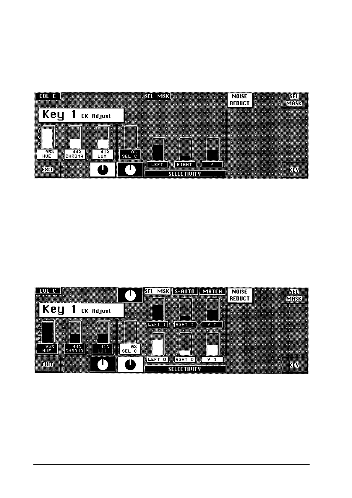
2.8 Operation of the keyer menus
Diamond digital DD10
2.8.7
HUE
,
CHROMA
CHROMA KEY ADJUST MENU
and
LUM
Display and adjustment of the key color parameters.
SEL-C
,
LEFT, RGHT
and Y
Display and adjustment of the selectivity parameters.
After
selecting
which
now can be separately adjusted:
SEL MSK, LEFT, RIGHT
and Y are
divided into two parameter sets
LEFT-O
RGHT-O
LEFT-I
RGHT-I and Y-I
52
,
and
,
Y-O
corresponds
Keyers
corresponds to the inner mask area.
to the outer mask area and remains controllable also
panel.
in the Chroma
Page 59

Diamond digital DD10
2.8 Operation of the keyer menus
After
an chroma key automatic run, first both sets are identical with the unmasked
set
LEFT, RGHT
and Y. Later deviations can be undone with
MATCH
.
SEL
MSK
MATCH
Y
COL C
Note: Masks
switches the maskability of the selectivity
draws the two selectivity sets xxx O and xxx I on the unmasked set
LEFT, RIGHT
Selectivity Y
separates in similar way colors which should not be changed from those which
have
to be deprived by their key color
the
luminance.
Purpose: To
Example: Yellow
COLOR
angle
after
While
so that the adjustability of HUE and CHROMA is improved.
CANCEL desaturates all colors of the fill signal which lie within a narrow
range around the key color in the color circle. COL C
each automatic run (not
pressing the KeyColor key
from the mask store will be lost when switching off the mixer!
ON or OFF
and
Y.
. Influencing parameter in this case is however
deprive also the
color
portion.
hair in front of a
Y
> 50%, the gray helos are increasingly deprived by blue with
increasing luminance: they become yellow
After
every AKA, selectivityY is set by default to 50% (ineffective).
achromatic (light saturated) colors by their key
blue wall effects gray helos. W
S–Auto
).
, the ColorCancel ef
ith Selectivity
.
is switched on by default
fect is temporarily cancelled
Y
ou will find further information in the corresponding sections of the Keyers panels.
53
Page 60

2.8 Operation of the keyer menus
2.8.8 FORGROUND FADE-MENU
Diamond digital DD10
LUMOFS
Also see FG Fade in the Keyers panel.
You
will find further information in the corresponding sections of the Keyers panels or in the descriptions of
the other Keyer menus.
positive luminance of
(only in the FG Fade mode).
Raises or lowers the luminance level in the transition areas.
Can be used in order to brighten too dark object edges
or to darken too bright edges, for better matching them to the
background scene.
fset to the subtractive key color luminance
54
Page 61

Diamond digital DD10
2.8 Operation of the keyer menus
2.8.9
Crop
DYNACHROME-MENU
In
the activated status,
for
analog signals. This is necessary if the signals of analogous Sources are deri
ved. The different blanking width result in black bars on the right and left picture
edge,
i.e. disturbances particularly in the case of key invert.
the blanking width of the mixer is changed over to blanking
-
Note: Function
You
will find further information in the corresponding sections of the Keyers panels or in the descriptions of
the other Keyer menus.
Crop
can also be called from other keyer menus.
55
Page 62

2.8 Operation of the keyer menus
Diamond digital DD10
56
Page 63

Diamond digital DD10
2.9 MATTES PANEL
The
ators
2.9 Mattes Panel
compact switcher
for designing matte backgrounds, wipe borders, key borders and captions.
Diamond digital DD10
includes 7
independent matte gener
-
MatteWash The MatteWash
extremely soft color wash ef
or
diagonal direction for picture design.
FractalTextures The
MatteStore The
WiperWash The WiperWash function offers a new possibility for wipe border designing. It is
new
FractalT
designing.
two
optional colors of a matte generator
new
MatteStore
signing
pictures.
possible
of
to perform color wash ef
function permits for each matte generator besides flat field colors,
fects between two optional colors in horizontal,
exture
The wipe signal of the wipe generator controls color washing
complex brightness and color wash ef
function of
, a volatile store for wipe or key signals,
fers new possibilities
.
fects as well as of monochromatic
fects within the border
for ef
.
fective background
permits creative de
vertical
between
-
57
Page 64
2.9 Mattes Panel
Diamond digital DD10
Mattes
BGD Matte BGD
system
the
background or preset bus.
Wipe1B Key1F
Wipe2B
Hue/Softness
Chroma/Position
Luminance/Angle
Matte
enables direct selection of the background matte. The auto delegation
Key1B Key2B
automatically selects the background matte when actuating
Key2F
BGD
Matte
Matte
1
flat
Matte
store
DSK F
DSK B
Matte
sel
Matte
2
wash
Wiper
wash
BGD Matte on
Matte sel Matte
sel
enables scrolling through
by
the auto delegation system has to be changed.
When scrolling, the order of the mattes is changed cyclically:
• Wipe1Border,
• Wipe2Border,
• Key1Fill,
• Key1Border,
• Key2Fill,
• Key2Border,
•
DSK Fill and
•
DSK Border
Matte 1, Matte 2 Matte 1 or Matte 2
Note: Please note that in case of unfavorable parameter settings, only one
.
matte will be visible in the wash or Matte store mode. In this case, we
recommend
the dif
ferent mattes when the matte suggested
key switches on the mattes to adjust the desired colors.
to switch over to the
flat
mode when adjusting the color
.
58
Page 65

Diamond digital DD10
Adjusting the color:
Hue
Chrominance
Luminance
Hue
The
control adjusts the color
color. The Luminance
. The
Chroma
control adjusts the intensity of the
control adjusts the brightness of the color
2.9 Mattes Panel
.
Hue/Softness
Chroma/Position
Luminance/Angle
flat
Note: Please note that certain combinations of chrominance and luminance
With
flat
, a flat field color can be selected.
wash With wash
Matte
1 and Matte 2.
If
only
wash
labeled
rotary controls
Pressing Matte 1 or Matte 2 enables adjustment of the matte using the Hue,
Chroma
and
values
will cause overlevels and illegal colors. For this reason, an auto
matic control limits for instance the chrominance for defined
luminance
values.
You
can easily check this by setting the chroma control to maximum posi
tion
and then turning the luminance control slowly to maximum position;
the
chrominance will be reduced with increasing luminance values.
, a color area can be selected, being composed of a
lights, it is possible to individually vary color wash with the
Softness, Position
Luminance
controls.
and
Angle.
color wash between
adequately
-
-
Softness The
Softness
between
Position The Position
Angle The Angle
control adjusts the steepness, i.e. the width of the
the two colors.
control shifts the position of the transition range.
control rotates the angle of the transition range.
transition range
Matte store Matte store being only effective for the background matte, modulates the color
wash
ef
fect between Matte 1 and Matte 2 by the wipe signal or key signal selected
for
the matte store.
For store control see the section
Wiper wash Wiper
effect
colors
Softness
The
border width can be adjusted with the
trol
on the
For wipe control see the section Wipe Panel
wash
being only active for the wipe border
in the wipe border
in such a way that a complete washing between the two
is made in the border
control.
Wipe panel.
Stores Panel
.
mattes, controls the color wash
. The softness of the transition can be adjusted with the
Bord
key and the associated rotary con
.
-
59
Page 66

2.9 Mattes Panel
Copying mattes
Diamond digital DD10
The
adjustments of a matte can be easily copied into another matte:
•
Press
Input Corr
•
Select with
•
Press
Matte 1 or Matte 2
• Select
with
to.
• Release
Matte 1 or Matte 2.
; the key lamp lights.
Matte sel or
Matte sel
BGD matte
or
BGD matte
the matte you want to copy
and hold the key down.
where you want to copy the adjustments
.
2.9.1 LIMITA
RGB limitation
PAL/NTSC
Function
limitation
TION OF THE COLOR TRIANGLE
The
new color triangle limitation (as from software
of
MA
TTE settings on
D
RGB color triangle
D P
AL/NTSC level
It
ensures that these limitation regulations are observed but also that the scope is
fully
exploited. Both regulations
tion
prevailing on a case by case basis.
These signals are derived from ME1.
All
colors are permitted that do not produce an R, G or B level of > 100% or <0% (this
means
that about 75% of all conceivable Cb/Cr/Y combinations are not permitted).
All colors are permitted as long as the total of luminance and chrominance does
not exceed the (adjustable) COL LIMITER level.
If
COL LIMITER is set to 133, a P
representation
COL
LIMITER is set to 100, a 100
will
be inadmissible.
If in a modification of hue, chroma, or luminance one of the limits is reached, the
switcher sends a BEEP signal (can be disabled) and attempts to realise the
demanded value at the expense of a dif
of
all RGB values (including a saturated yellow) will be possible. If
version ”F”) controls the ef
are applicable at all times with the stricter regula
AL/NTSC overlevel of 33 % will admissible but the
% level will be ensured but certain (yellow) colors
ferent parameter.
fects
-
Limit mode ON/OFF
60
A change in HUE may result in a chrominance correction.
D
D
A change in CHR may result in a luminance correction.
D
A change in LUM may result in a chrominance correction.
If
an absolute limit is reached, no value will change any longer
may
generally be achieved at a medium luminance, i.e. subsequent decreases or
increases
The
is
enabled, when chrominance is set to maximum.
In subsequent HUE changes, the color follows lines of maximum saturation. For
this
ically. If the chrominance or luminance setting is changed, this mode is disabled
again.
in LUM will result in a reduction in chrominance.
limit mode simplifies the search for colors with maximum saturation. This mode
purpose, both chrominance and luminance are continuously updated
. A maximum
chroma
automat
-
Page 67

Diamond digital DD10
2.9 Mattes Panel
Note: There
ware
(e.g. changed COL LIMITER). To achieve a clear, stable status, we
recommend
second
may be
versions are recalled
problems if mattes stored in EXTRA under older soft
storing the recalled and corrected (if
time.
-
and are now confronted with stricter limits
applicable) mattes a
61
Page 68

2.9 Mattes Panel
Diamond digital DD10
62
Page 69

Diamond digital DD10
2.10 W
ipe Panel
2.10
WIPE P
ANEL
The compact switcher Diamond digital DD10 includes up to two wipe generators
which can be optionally used for background or key transitions as well as for designing
masks or modulating the background matte.
Wipe
2nd
Rot
User
Text
Lock
Mod
H
Mod
Extend
pos
Pos
Flip
Flop
Rev
Masks
Forc
FGND
Pattn
1
Box
Mask
PVW
Modif
reset
Mask
inv
Pattn
2
Mask
Store
Delegation
wipe generator
Mod
On
ModVMulti
A B C D A B C D A B C D
On
The delegation keys
panel
for the
dif
ferent applications. Wipe generator 2 is available as an option only
On
Wipe
Comb
On On
Wipe
Rot
Wipe 1, Wipe 2
Bord
and
A B C D
On
Soft
Mask
On
Aspect
Delegation
Wipe
1
enable switching over the Wipe
Mask
Wipe
2
.
63
Page 70

2.10 W
ipe Panel
Diamond digital DD10
Pattern selection The
terns
15
the lower part of the selection key
Further
rotation
The
cating
pattern selection panel enables direct selection of 15 wipe patterns. These
are shown in the upper part of the selection key
more patterns can be selected with the
2nd
.
key
. These patterns are shown in
.
patterns can be selected by actuating the Rotation/User
key
. In this mode,
wipes are available in addition to the standard wipe patterns.
insertable legend plates of the keys show the possible rotation wipes by indi
the center of rotation and the wipe direction.
RANDOM
pat
-
-
USER 1
RWD
USER 2
REV
USER 3
STOP
USER 4
Play
USER 5
FFWD
User-defined wipe patterns (User 1...5)
Beside the standard patterns, the Diamond digital DD10 offers the possibility of
preparing
lects
and storing user-defined patterns. A simple stroke
these patterns directly
.
of
User 1...5
also se
Preadjustment:
•
Adjustment of the desired pattern with all its modifications.
•
Hold down
•
Select the desired storage location by pressing one of the
•
Storage is indicated by a short lighting-up of the corresponding User key
Rot/User.
User 1...5
keys.
.
-
64
Page 71

Diamond digital DD10
2.10 W
ipe Panel
DVE ef
fects
Via an RS 422 remote interface, the mixer can control some functions of defined
DVE devices.
These functions are:
D Ef
fect selection
D
Positioning within the ef
D T
ape motion commands “TMC” (PLAY, STOP, REVERSE, REWIND, FFWD)
fect
DVE Effect
ABEKAS A53D
ABEKAS A57
AMPEX ADO
GVG DPM-700
QUESTECH
CHARISMA
PINNACLE PRIZM
selection
yes yes yes
yes yes yes
yes yes –
yes yes yes
yes yes –
yes yes –
Effect
position
TMC Protocol
DVE A53D
DVE A53D
DVE ADO
DVE DPM
DVE CHARIS
DVE PRIZM
name
Note
Only Port1
connector RS-232
Only Port1
connector RS-232
Special cable
required
Wipe direction
Pattern
positioning
Flip
Flop
determines the wipe direction.
is
changed every time the lever is moved to a limit or the transition is completed.
Rev
changes the preset wipe direction.
Pos
activates the trackball on the Positioner panel. The trackball
to
position the center of the selected pattern within the visible picture section.
Note: Please
be
Extend
Pos
note that some wipe patterns (e.g. matrix
positioned.
activates the trackball on the Positioner panel. The trackball enables
In the activated state, the wipe direction
enables the user
wipe patterns) cannot
the user to position the center of the selected pattern at any place, even outside
the
the visible picture section.
Note: Please
fore
note that in this mode, the wipe transition may reach its limit be
the wipe pattern fully crosses the screen.
-
65
Page 72

2.10 W
ipe Panel
Diamond digital DD10
Textures
Text
enables the
nally
stored textures and store them in the matte store.
Activating
which
switches off Freeze.
As
long as Text
pattern
Multi,
If
as
•
•
When
switching on T
Note: Please note that the textures are only possible with the wipe generator
Tips:
selection keys, which can
Wipe Comb, Wipe Rot, Bord, Soft
these changed patterns have to be constantly used in future, they
follows:
Press the
press the desired key on the pattern selection keyboard.
switching off Tex
of
Fading is possible with almost all textures.
The
also
terns
user
, in connection with the pattern selection keys, to recall inter
the
Text
key leads the
is switched on, the available wipe patterns can be recalled with the
Rot/User
ext, is restored.
mixing level ME1.
currently adjusted pattern can be stored as user pattern and is then
available outside the texture mode.
can also be recalled in the texture mode.
key and hold it down,
t, the matte store is frozen and the pattern adjusted before
signal of the wipe generator into the matte store
be individually changed with the modifiers
and
Aspect.
can be stored
In the opposite way
, the user pat
Mod,
-
-
Especially
ator
•
•
•
•
The
can be stored individually or as a part of ”User-Data” or ”All setups” on
a
disk, or be read off the disk. See the section
beautiful patterns obtained when playing with the wipe
can be stored as a texture as follows:
Store the pattern as a user pattern
Activate the T
Recall the user pattern
Store the pattern as a texture
texture patterns are contents of the RAM-Files TEXTURES. This file
ext key
Disk and File Menu.
gener
-
66
Page 73

Diamond digital DD10
Wipe modifier
2.10 W
ipe Panel
Wipe
2nd
Rot
User
Text
Lock
H
Mod
Mod
On
ModVMulti
A B C D A B C D A B C D
On
On
Wipe
Comb
On On
Wipe
Rot
Bord
On
Soft
Ext
pos
Pos
Flip
Flop
Rev
A B C D
On
Aspect
Masks
Forc
FGND
Pattn
1
Box
Mask
PVW
Modif
reset
Mask
Delegation
Wipe
1
Mask
inv
Pattn
2
Mask
store
Wipe
2
By
means of the modifier keys
Mod, Multi, W
ipe Comb, W
ipe Rot, Bord, Soft
and
Aspect, the standard wipe patterns can be changed and even new patterns can
be
created by combinations of patterns.
Modif
reset
switches of
position.
mal
The
modifiers are
being
controlled by the controls located above. Function and number of the controls
vary
in dependence on the selected modifier
The
adjustments of the modifiers are mutually exclusive. The state is indicated by
the On
display above
f the enabled modifiers all at once
switched on and of
f by pressing the key
and resets them to nor
, the respective function
.
the key. The key lamps show the modifier that the controls
are assigned to.
When
switching among the individual modifiers, the adjusted
cally
stored and again available when recalling.
values are automati
-
-
67
Page 74

2.10 W
ipe Panel
Diamond digital DD10
Mod Mod
The following adjustments are possible:
AMPL
SPD
MULT
SHAP
Beside
be
also influenced with the following keys:
H Mod
V Mod
Lock Mod Modulation
Multi Multi
The following adjustments are possible:
H
V V
O Multiplication
X
activates wipe edge modulation.
Modulation amplitude
Modulation speed
Modulation frequency
Modulation shape (square, triangle, sinewave)
these adjustment possibilities, the wipe edge modulation can
Horizontal wipe edge modulation only
V
ertical wipe edge modulation only
is locked, i.e. the modulation is not freerunning,
stationary on the screen
activates wipe pattern multiplication.
Horizontal multiplication
terns
Number of star points for star wipe and flower
but the
ertical multiplication
only (e.g. circle)
modulation edge will appear to be
in radial direction, for
closed wipe pat-
W
ipe Comb
Wipe
Comb
combined pattern).
Pressing
lowing
MIX
NAM
The
controls enable the user to adjust the variety of combinations. In
the
NAM mode, another
sense
Selection
with
the Wipe Comb
pattern is made on the pattern selection panel with the W
function switched on. In the wipe comb mode, the keys of both in-
volved
combines two dif
the Wipe Comb
combinations:
Multiplicative mixing of two patterns
Non-additive mixing of two patterns
of rotation.
of the main pattern is made on the pattern selection panel
function
patterns are lit on the pattern selection panel.
ferent wipe patterns ( main pattern and
key repeatedly enables selection of the
combination can be achieved by a dif
switched off
. Selection of the combined
ipe Comb
fol
ferent
-
68
Page 75

Diamond digital DD10
Example for application:
MIX
Circle + square
NAM
Circle + square
2.10 W
ipe Panel
Note:
Wipe Rot Wipe Rot
Bord Bord
Please note that not all combinations are possible.
Locked are
–
wipe patterns with the same basic patterns,
–
wipe patterns already being combined patterns,
– wipe
patterns having their origin or
ner
or at the picture edge.
Pressing
ment
possibilities:
ANGL
SPD
COUP Rotation
activates wipe pattern bordering.
The following adjustments are possible:
WIDT Adjustment
OPAC
center of rotation in a picture cor
activates wipe pattern rotation.
the key repeatedly
Adjustment of a fixed rotation angle
Adjustment of the rotation speed
number
trol.
can be adjusted by cw or ccw rotation.
When
the
sense of rotation
can
determine the picture component to
the border.
Adjustment of the border transparency
, cyclically provides the following
angle depends on the fader position. The
of rotations can be selected with the con-
of the border width. The border width
the border is adjusted with Opac transparent,
of the border width adjustment
adjust
be seen in
-
-
If
the
Soft
possibilities
SOFT
SYM
modifier has been also selected, the following adjustment
are additionally available:
Adjustment of the border softness
Adjustment of the softness symmetry
69
Page 76

2.10 W
ipe Panel
Diamond digital DD10
Soft Soft
Aspect Aspect
adjusts the softness of the wipe edge.
The following adjustments are possible:
SOFT
If
the
Bord
possibilities
WIDT
OPAC
SYM
The following adjustments are possible:
H-ST
V-ST
RATio By
Adjustment of the softness width
modifier
are additionally available:
adjusts the aspect ratio of the wipe pattern.
has been also selected, the following adjustment
Adjustment of the border width. The border width
can be adjusted by cw or ccw rotation.
When
the border
the
sense of rotation of the border width adjustment
can
determine the picture component to be seen in
the border
Adjustment of the border transparency
Adjustment of the softness symmetry
Stretch in horizontal direction
Stretch in vertical direction
cw or ccw rotation, stretching can be made
horizontal
is adjusted with Opac transparent,
. Clockwise rotation.
or vertical direction
in
Copying
wipe settings
SIZE
Note:
The settings of one wipe generator can be easily copied to the other one.
•
• Select
• Select
When
the
When enabling control of a modifier
The SIZE
–
–
Please note that in the stretch mode, a linear piece is inserted into the
wipe
pattern. In the ratio mode, the H:V aspect ratio is changed.
Also note the border widths in the stretch and ratio modes.
Press
Input Corr
with the delegation keys Wipe 1
to
copy
.
with the other delegation key the wipe generator you want to copy the
to. All settings will be transferred to the selected wipe generator
setting
using the wipe generator for another function than for background transition,
size of the pattern can be adjusted with the
function can be re-activated by
disabling the respective modifier selection and
pressing the delegation key for the respective wipe.
; the key lamp lights.
, the
or Wipe 2
SIZE
the wipe generator you want
SIZE
control.
function is disabled.
-
.
70
Page 77

Diamond digital DD10
2.10 W
ipe Panel
2.10.1
WIPE SELECTION CODE FOR CONTROL P
enclosed list contains all wipe patterns available in the switcher together with
The
their specific wipe number (in line with SMPTE). The table also indicates which
modifiers
All wipe patterns that cannot be directly selected with the wipe selection keypad
may
The register number to be selected is the listed SMPTE wipe number plus
Example:
"
"
"
"
"
are possible with the individual wipe patterns.
be recalled with a register selection in the EXTRA panel.
Selection of wipe no
No EXTRA function selected.
Enter register no.
Press
Enter.
Wipe pattern is recalled.
The wipe pattern may subsequently be stored as a user wipe and
is thus directly available by simple key actuation.
338
.
ANEL AND EDIT
138 (= register 338)
OR OPERA
TION
200.
Note:
For DD5 switchers only the basic pattern can be used!
71
Page 78

W
ipe Panel
Wipe
Note: SOFTNESS and BORDER is possible with all patterns.
SMPTE
Wipe No.
(Wipe No
for SONY
Editors)
Matxix wipe
Fraktal or not comb
–
Sensetive for 16/9
X-Multi
Ratio
Position
H-Modulation
H-Multi
V-Modulation
V-Multi
Diamond digital
V-Stretch
H-Stretch
Rotation
O-Multi
01
02
03
04
05
D D
D D
D D D D D D D D D
D D D D D D D D D
D D D D D D D D D
72
06
07
D D D D D D D D D
D D D D D D D D D
Page 79

Diamond digital
Wipe
SMPTE
Wipe No.
(Wipe No
for SONY
Editors)
Matxix wipe
Fraktal or not comb
–
Sensetive for 16/9
X-Multi
Ratio
Position
H-Modulation
H-Multi
V-Modulation
Wipe-Bedienfeld
V-Multi
H-Stretch
Rotation
V-Stretch
O-Multi
RECALL
USER WIPE 1
FROM EDIT
SYSTEM
RECALL
USER WIPE 2
FROM EDIT
SYSTEM
OFF
OFF
RECALL
USER WIPE 3
FROM EDIT
SYSTEM
RECALL
USER WIPE 4
FROM EDIT
SYSTEM
OFF
OFF
09
10
11
12
13
D D D D D D D D D D D
RECALL
USER WIPE 5
FROM EDIT
SYSTEM
OFF
14
20
21
D D D D D D D D D D D
D D D
73
Page 80

Wipe-Bedienfeld
Diamond digital
SMPTE
Wipe No.
Wipe
(Wipe No
for SONY
Editors)
22
23
24
Matxix wipe
Fraktal or not comb
–
Sensetive for 16/9
X-Multi
Ratio
Position
H-Modulation
H-Multi
V-Modulation
V-Multi
H-Stretch
Rotation
V-Stretch
D D D
D D D D D D D D D
D D D D D D D D D
O-Multi
25
26
27
28
29
D D D D D D D D D
D D D D D D D D D
D D D D D D D
D D D D D D D
D D D D D D D
74
Page 81

Diamond digital
Wipe-Bedienfeld
SMPTE
Wipe No.
Wipe
(Wipe No
for SONY
Editors)
30
41
42
Matxix wipe
Fraktal or not comb
–
Sensetive for 16/9
X-Multi
Ratio
H-Modulation
H-Multi
V-Modulation
Position
D D D D D D D
D D D D D
D D D D D
V-Multi
H-Stretch
Rotation
V-Stretch
O-Multi
45
46
47
61
62
D D D D D
D D D D D
D D D D D D D D D
D D D D D D D D D
D D D D D D D D D
75
Page 82

Wipe-Bedienfeld
Diamond digital
SMPTE
Wipe No.
Wipe
(Wipe No
for SONY
Editors)
63
64
80
Matxix wipe
Fraktal or not comb
–
Sensetive for 16/9
X-Multi
Ratio
Position
H-Modulation
H-Multi
V-Modulation
V-Multi
H-Stretch
Rotation
V-Stretch
D D D D D D D D D
D D D D D D D D D
D D D
O-Multi
81
82
83
85
86
D D D
D D D
D D D
D D D
D D D
76
Page 83

Diamond digital
Wipe-Bedienfeld
SMPTE
Wipe No.
Wipe
(Wipe No
for SONY
Editors)
87
88
89
Matxix wipe
Fraktal or not comb
–
Sensetive for 16/9
X-Multi
Ratio
Position
H-Modulation
V-Modulation
D D D
D D D
D D D
H-Multi
V-Multi
H-Stretch
Rotation
V-Stretch
O-Multi
92
93
94
95
100
(99)
D D D
D D D
D D D
D D D
D D D D D D D D
77
Page 84

Wipe-Bedienfeld
Diamond digital
SMPTE
Wipe No.
Wipe
(Wipe No
for SONY
Editors)
101
(69)
102
(96)
103
(97)
110
(98)
Matxix wipe
Fraktal or not comb
–
Sensetive for 16/9
X-Multi
Ratio
Position
H-Modulation
H-Multi
V-Modulation
V-Multi
H-Stretch
Rotation
V-Stretch
D D D D D D D D D D
D D D D D D D D D D
D D D D D D D D D D D D
D D D D D D D D D D D
O-Multi
119
(49)
120
(50)
122
124
(70)
D D D D D D D D D D D
D D D D D D D D D D D
D D D D D D D D D D D
D D D D D D D D D D D
78
Page 85

Diamond digital
Wipe-Bedienfeld
SMPTE
Wipe No.
Wipe
(Wipe No
for SONY
Editors)
130
132
133
Matxix wipe
Fraktal or not comb
–
Sensetive for 16/9
X-Multi
Ratio
Position
H-Modulation
H-Multi
V-Modulation
V-Multi
H-Stretch
Rotation
V-Stretch
D D D D D D D D
D D D D D D D D D D D D D
D D D D D D D D D D D D D
O-Multi
134
135
136
137
138
D D D D D D D D D D D
D D D D D D D D D D D
D D D D D D D D D D D
D D D D D D D D D D D D
D D D D D D D D D D D
79
Page 86

Wipe-Bedienfeld
Diamond digital
SMPTE
Wipe No.
Wipe
(Wipe No
for SONY
Editors)
140
141
142
Matxix wipe
Fraktal or not comb
–
Sensetive for 16/9
X-Multi
Ratio
Position
H-Modulation
H-Multi
V-Modulation
V-Multi
H-Stretch
Rotation
V-Stretch
D D D D D D D D D D D D
D D D D D D D D D D D D
D D D D D D D D D D D D
O-Multi
143
144
145
146
147
D D D D D D D D D D D D D
D D D D D D D D D D D D D
D D D D D D D D D D D D D
D D D D D D D D D D D D D
D D D D D D D D D D D D D
80
Page 87

Diamond digital
Wipe-Bedienfeld
SMPTE
Wipe No.
Wipe
(Wipe No
for SONY
Editors)
148
149
150
Matxix wipe
Fraktal or not comb
–
Sensetive for 16/9
X-Multi
Ratio
Position
H-Modulation
H-Multi
V-Modulation
V-Multi
H-Stretch
Rotation
V-Stretch
D D D D D D D D D D D D D
D D D D D D D D D D D D
D D D D D D D D D D D D
O-Multi
151
152
182
(58)
183
(60)
184
(57)
D D D D D D D D D D D D
D D D D D D D D D D D
D D D D D
D D D D D
D D D D D
81
Page 88

Wipe-Bedienfeld
Diamond digital
SMPTE
Wipe No.
Wipe
(Wipe No
for SONY
Editors)
185
(59)
186
187
Matxix wipe
Fraktal or not comb
–
Sensetive for 16/9
X-Multi
Ratio
Position
H-Modulation
H-Multi
V-Modulation
D D D D D
D D D D D
D D D D D
V-Multi
H-Stretch
Rotation
V-Stretch
O-Multi
188
189
190
191
(51)
192
(52)
D D D D D
D D D D D
D D D D D
D D D D D D D
D D D D D D D
82
Page 89

Diamond digital
Wipe-Bedienfeld
SMPTE
Wipe No.
Wipe
(Wipe No
for SONY
Editors)
193
(53)
194
(54)
195
(56)
Matxix wipe
Fraktal or not comb
–
Sensetive for 16/9
X-Multi
Ratio
Position
H-Modulation
V-Modulation
H-Multi
V-Multi
D D D D D D D
D D D D D D D
D D D D D D D
H-Stretch
Rotation
V-Stretch
O-Multi
196
201
202
203
204
D D D D D D D
D D D D D D D
D D D D D D D
D D D D D D D
D D D D D D D
83
Page 90

Wipe-Bedienfeld
Diamond digital
SMPTE
Wipe No.
Wipe
(Wipe No
for SONY
Editors)
205
207
210
Matxix wipe
Fraktal or not comb
Sensetive for 16/9
–
V-Modulation
X-Multi
Ratio
Position
H-Modulation
H-Multi
V-Multi
D D D D D D D
D D D D D D D
D D D D D D D
H-Stretch
Rotation
V-Stretch
O-Multi
211
213
214
235
244
D D D D D D D
D D D D D D D
D D D D D D D
D D D D D
D D D D D
84
Page 91

Diamond digital
SMPTE
Wipe No.
Wipe-Bedienfeld
Wipe
Only with wipe processor
hardware index 12 or higher
(Wipe No
for SONY
Editors)
247
128
(75)
Matxix wipe
Fraktal or not comb
–
Sensetive for 16/9
X-Multi
Ratio
Position
H-Modulation
H-Multi
V-Modulation
V-Multi
Rotation
V-Stretch
H-Stretch
D D D D D
D D D D D D D D D D D D D
O-Multi
85
Page 92

W
ipe Panel
Diamond digital
86
Page 93

Diamond digital DD10
2.11 MASKS PANEL
The compact switcher Diamond digital DD10 has extensive masking capabilities
by
square
rator
A key or pattern signal can be stored. The PaintModeMasking feature permits
creation
2.1
1 Masks Panel
means of
can be used for masking. The volatile mask store of
which also dif
ficult picture patterns can be corrected. For the keyers,
masks are available. Alternatively
, also
the wipe patterns of the wipe gene
fers new ways of masking.
of own masks which are optimally matched to the individual requirements.
Masks
-
Forc
FGND
Pattn
1
Box
Mask
PVW
Modif
Reset
Mask
Delegation
Wipe
1
Mask
inv
Pattn
2
Mask
store
Wipe
2
Creating
a box mask
The
which
Box Box
the
keys
Pattn 1, Pattn 2, Box
and
Mask store
enable selection of the mask type
has to be used for masking.
selects a square mask for masking. The size of the mask can be adjusted with
four controls
LEFT, RIGHT, T
L
E F T
R I G H T O P B O T T
OP
and
BOTT
OM on the Wipe panel.
87
Page 94

2.1
1 Masks Panel
Adjusting the mask position
With
See
Diamond digital DD10
the trackball on the Positioner panel, the mask can be optionally positioned.
the section
Positioner Panel
.
Modif Reset Pressing Modif Reset
1/3H
Delegation
and 1/3V
The auto delegation system automatically switches over the Wipe panel to mask
control
when pressing
by
pressing
.
Mask
on the Delegation panel.
generates a box mask in the picture center having the size
Box
. Switchover of the Wipe panel can be also performed
Mask
Delegation
Wipe
Wipe
1
2
88
Page 95

Diamond digital DD10
Creating a wipe mask
2.1
1 Masks Panel
Pattn 1, Pattn 2 Using Pattn 1
The wipe pattern can
panel. The size of the wipe pattern can be adjusted with the SIZE control on the
panel.
Wipe
The
wipe
mask can be positioned with the trackball on the Positioner panel. For this
purpose,
previously activate
The wipe mask can be optionally positioned in the picture.
Further
details about wipe pattern control are contained in the section Wipe Panel
Note: Please note that the wipe generators can be used at the same time for
different
or
Pattn 2
, one of the wipe generators
can be selected for masking.
be directly selected with the wipe selection keys on the Wipe
S I Z E
Pos
on the Wipe panel.
applications which may interact with one another
.
.
Mask store Mask
store
automatically
Further details about store control and PaintModeMasking are contained in the
section Stores Panel
Forc FGND Pressing
ses (masked) or forces the foreground picture. When the key lights, forced foreground
is activated.
Mask inv Mask inv
With
a square mask, for instance, the contents of the square is not used any more
for
masking but the outer field of the square.
Mask PVW
Pressing the associated function key highlights the mask signal on the preview
monitor.
function serves the adjustment of the mask.
The
Note:
selects
the mask store as a mask source. The auto delegation system
switches over the Stores panel to mask store control.
.
the assiciated function key permits to select whether the mask suppres
inverts the mask signal.
In
the Mask PVW mode, the mask
is only represented as 1-bit signal. If
you want to exactly position a mask with softness, switch on the mask
the
with
Mask on
key on the Keyers panel.
-
89
Page 96

2.1
1 Masks Panel
Diamond digital DD10
90
Page 97

Diamond digital DD10
2.12 POSITIONER PANEL
The wipe generators and the mask generators in the compact switcher Diamond
digital
DD10
with PaintModeMasking, the trackball serves to use the cursor as a ”brush” or
”rubber”.
2.12 Positioner Panel
can be sensitively positioned with the trackball. For mask generation
Positioner
H Lock, V Lock H
H
M S K 1
lock
and
V lock
permit locking the trackball in H or V direction. Thus, it is pos
sible,
for instance, to exactly position a wipe pattern along a horizontal or vertical
Lock Lock
Cent
V
line.
Note:
When both keys are pressed, the trackball is locked.
-
Center Center
The
display to the left of the keys shows the function which can be influenced
the
trackball.
The following displays are possible:
W I P 1W I P 2M S K 1 M S K 2 M S K 3
The
auto delegation system automatically assigns the trackball to the function used
by you. If the trackball has to be assigned to another function, select the corresponding
The definition of the trackball
spective requirements. See the section
re-positions the trackball back to the center of the screen.
K E Y 1
K E Y 2
S T 1 M
function on the respective panel.
can be easily matched in the setup mode to the re
Setup.
with
-
91
Page 98

2.12 Positioner Panel
Diamond digital DD10
92
Page 99

Diamond digital DD10
2.13 STORES PANEL
The
signals
without
Video
in
as a freeze picture.
Matte
lation
tures.
Mask store enables storing a key or wipe signal or creating own masks with
PaintModeMasking.
compact switcher
Diamond digital DD10
includes three volatile stores for video
and key or mask signals by means of which new ef
using external units.
store
enables storing a 4:2:2 video signal which can subsequently be faded
store
enables storing a
of the background matte. Matte store
key or wipe signal which can then be used for modu
is also used for storage of
Stores
2.13 Stores Panel
fects can be
FractalTex-
generated
-
Store delegation
Field
Mask
store store store
Pattn
Paint
mode
The
delegation keys
trol
functions to one of the three stores.
Mask store, Matte store
Matte
Key
Paint
Video
Mask
shift
Rub
Field
Freeze
Clear
and Video store
delegate the con
Field enables selecting for each store separately whether both fields or one de-
field should be read out of the store. The key is operable for all stores.
fined
Pressing the key repeatedly
For
the mask store, also
mode,
thus enabling to avoid field flickering when storing.
•
FRAME (key lamp of
•
1st FIELD (key lamp on)
•
2nd FIELD (key lamp on)
, cycles though 3 operational states:
the read-in operation can be switched over to field or frame
f)
-
Freeze
Freeze
enables storing a picture signal. The key lamp is lit in the freeze mode
Note: Please
the
store.
note that a signal is delayed by one frame when passing through
93
Page 100

2.13 Stores Panel
Diamond digital DD10
Video store
Matte store
Mask store
Storage of a video picture has to be performed as follows:
• Activate Video store on the Aux Bus and subsequently select a picture
source.
puts
Beside the input sources,
Preview or Program
of course also the matte signals or the out
can be selected.
• The stored picture signal can be recalled as an input signal on the Source
Selection
Storage of a background has to be performed as follows:
• Select
stored
• For
Wipe
quently
• If
a texture has to be stored in the matte store, press
select
• In
order to assign a key signal as a source to the store, hold down
multaneously
panel.
The required adjustments can subsequently be made on the Keyers panel.
Storage of a mask has to be performed as follows:
panel using the keys
with
Pattn
or
Key
on the Stores panel the signal type which has to
in the matte store.
storing a wipe signal, hold down
2
on
the Wipe panel. The desired wipe and the modification can subse
be selected on the Wipe panel.
a texture with the pattern selection keys.
select the desired keyer with
2nd
and
Video store.
Pattn
and
simultaneously select Wipe 1
Text
on the Wipe panel and
Key 1, Key 2
or
DSK
on the Keyers
Key
be
or
and si
-
-
-
•
Select with
stored in the mask store.
• In
order to assign a key signal as a source to the store, hold down
multaneously select the desired keyer using Key 1, Key 2 or DSK on the
Keyers
The required adjustments can subsequently be made on the Keyers panel.
• For
storing a wipe signal, hold down
Wipe
quently
• Clear
• Mask shift
Pattn
or Key
panel.
2
on
the Wipe panel. The desired wipe and the modification can subse-
be selected on the Wipe panel.
deletes the contents of the mask store.
enables shifting the output picture of the store with the trackball.
on the Stores panel the signal type which has to be
Key
Pattn
and
simultaneously select Wipe 1
and si-
or
94
 Loading...