

Page 1

CR Series
Compact Routers and Control Panels
User’s Guide
UG1600-14
2 Dec 2014
Page 2

Copyright & Trademark Notice
Copyright © 2014 Grass Valley. All rights reserved.
Belden, Belden Sending All The Right Signals, and the Belden logo are trademarks or
registered trademarks of Belden Inc. or its affiliated companies in the United States and
other jurisdictions. Grass Valley, NVISION, NV9000, CR6400, and CR Series are trademarks or
registered trademarks of Grass Valley. Belden Inc., Grass Valley, and other parties may also
have trademark rights in other terms used herein.
Terms and Conditions
Please read the following terms and conditions carefully. By using CR Series documentation,
you agree to the following terms and conditions.
Grass Valley hereby grants permission and license to owners of CR Series routers to use their
product manuals for their own internal business use. Manuals for Grass Valley products may
not be reproduced or transmitted in any form or by any means, electronic or mechanical,
including photocopying and recording, for any purpose unless specifically authorized in
writing by Grass Valley.
A Grass Valley manual may have been revised to reflect changes made to the product during
its manufacturing life. Thus, different versions of a manual may exist for any given product.
Care should be taken to ensure that one obtains the proper manual version for a specific
product serial number.
Information in this document is subject to change without notice and does not represent a
commitment on the part of Grass Valley.
Warranty information is available in the support section of the Grass Valley web site
(www.grassvalley.com).
Title CR Series Routers User’s Guide
Part Number UG1600-14
Revision 3.2 (02 Dec 14)
ii
Page 3
CR Series
User’s Guide
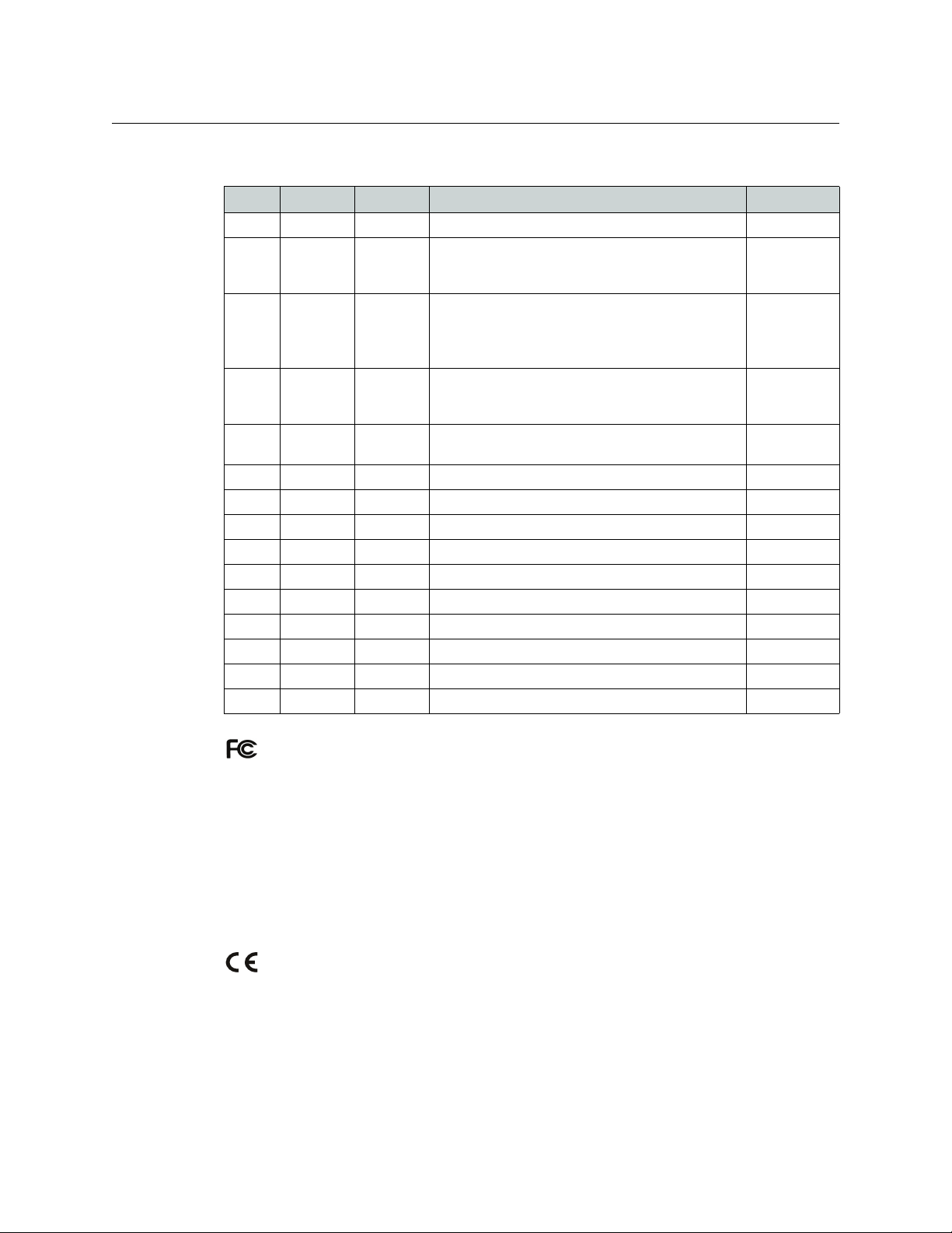
Change History
Rev. Date ECO Description Approved
1.0 03 Apr 06 — Initial Release —
1.1 14 Nov 06 12390 Added material regarding -AES routers, 32×32
routers, network operation, 16×4 router, and 16×4
and 16×2 control panels. Corrected a few problems.
1.2 04 Jan 07 12440 Added material regarding -AV routers, remote panel
modules, CrConfig (software), and compact router
networks.
Created button legend templates.
1.3 12 Jul 07 13355 Added material regarding analog audio routers,
machine control routers, and “3Gig” routers.
Automation is now possible.
1.4 19 Nov 08 14426 References the CRSC software. Includes new CR
Series products. Misc. corrections.
1.5 30 Mar 09 15703 Format change. D. Cox
1.6 12 Oct 09 16114 Added new CR Series products, NV9000 support. D. Cox
2.0 22 Mar 10 16912 Added CQX series. D. Cox
2.1 04 May 10 16993 Added ± 3-line buffer. D. Cox
2.2 18 Aug 10 17186 Short addition regarding 3-line buffer. D. Cox
2.3 30 Mar 12 17286 Added 3Gig routers D. Cox
2.4 15 Nov 13 19037 Improvements to CQX series. D.Cox
3.0 28 May 14 19241 Added new CR6400 family products. D.Cox
3.2 03 Oct 14 19332 Phase 2 of CR6400 products. D.Cox
3.2 02 Dec 14 19357 New contacts. D.Cox
D. Cox
D. Cox
D. Cox
D. Cox
FCC Statement
This equipment has been tested and found to comply with the limits for a Class A digital
device, pursuant to part 15 of the FCC Rules. These limits are designed to provide reasonable
protection against harmful interference when the equipment is operated in a commercial
environment. This equipment generates, uses, and can radiate radio frequency energy and,
if not installed and used in accordance with the instruction manual, may cause harmful
interference to radio communications. Operation of this equipment in a residential area is
likely to cause harmful interference in which case the user will be required to correct the
interference at his own expense.
Declaration of Conformance (CE)
All of the equipment described in this manual has been designed to conform with the
required safety and emissions standards of the European Community. Products tested and
verified to meet these standards are marked as required by law with the CE mark.
When shipped into member countries of the European Community, this equipment is
accompanied by authentic copies of original Declarations of Conformance on file in Grass
Valley offices in Grass Valley, California USA.
iii
Page 4

Software License Agreement and Warranty Information
Contact Grass Valley for details on the software license agreement and product warranty.
Important Safeguards and Notices
This section provides important safety guidelines for operators and service personnel.
Specific warnings and cautions appear throughout the manual where they apply. Please
read and follow this important information, especially those instructions related to the risk
of electric shock or injury to persons.
WAR NIN G
Any instructions in this manual that require opening the equipment cover or enclosure are for use by
qualified service personnel only. To reduce the risk of electric shock, do not perform any service other
than that contained in the operating instructions unless you are qualified to do so.
Restriction on Hazardous Substances (RoHs)
Grass Valley is in compliance with EU Directive RoHS 2002/95/EC governing the restricted
use of certain hazardous substances and materials in products and in our manufacturing
processes.
Grass Valley has a substantial program in place for RoHS compliance that includes significant
investment in our manufacturing process, and a migration of Grass Valley product electronic
components and structural materials to RoHS compliance.
It is our objective to maintain compliance with all relevant environmental and product
regulatory requirements. Detailed information on specific products or on the RoHS program
at Grass Valley is available from Grass Valley Customer Support at
1-800-719-1900 (toll-free) or
1-530-265-1000 (outside the U.S.).
iv
Page 5
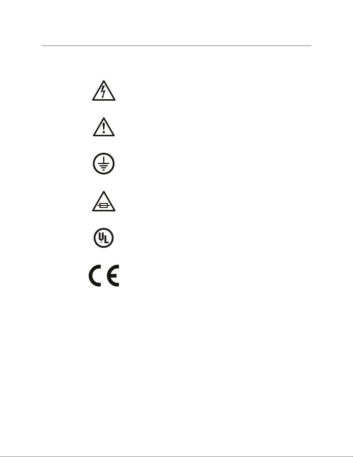
Symbols and Their Meanings
The lightning flash with arrowhead symbol within an equilateral triangle alerts the
user to the presence of dangerous voltages within the product’s enclosure that
may be of sufficient magnitude to constitute a risk of electric shock to persons.
The exclamation point within an equilateral triangle alerts the user to the presence
of important operating and maintenance/service instructions.
The Ground symbol represents a protective grounding terminal. Such a terminal
must be connected to earth ground prior to making any other connections to the
equipment.
The fuse symbol indicates that the fuse referenced in the text must be replaced
with one having the ratings indicated.
CR Series
User’s Guide
The presence of this symbol in or on Grass Valley equipment means that it has been
designed, tested and certified as complying with applicable Underwriter’s
Laboratory (USA) regulations and recommendations.
The presence of this symbol in or on Grass Valley equipment means that it has been
designed, tested and certified as essentially complying with all applicable
European Union (CE) regulations and recommendations.
General Warnings
A warning indicates a possible hazard to personnel which may cause injury or death.
Observe the following general warnings when using or working on this equipment:
• Heed all warnings on the unit and in the operating instructions.
• Do not use this equipment in or near water.
• This equipment is grounded through the grounding conductor of the power cord. To
avoid electrical shock, plug the power cord into a properly wired receptacle before connecting the equipment inputs or outputs.
• Route power cords and other cables so they are not likely to be damaged.
• Disconnect power before cleaning the equipment. Do not use liquid or aerosol cleaners; use only a damp cloth.
• Dangerous voltages may exist at several points in this equipment. To avoid injury, do
not touch exposed connections and components while power is on.
v
Page 6

• Do not wear rings or wristwatches when troubleshooting high current circuits such as
the power supplies.
• To avoid fire hazard, use only the specified fuse(s) with the correct type number, voltage
and current ratings as referenced in the appropriate locations in the service instructions or on the equipment. Always refer fuse replacements to qualified service personnel.
• To avoid explosion, do not operate this equipment in an explosive atmosphere.
• Have qualified service personnel perform safety checks after any service.
General Cautions
A caution indicates a possible hazard to equipment that could result in equipment damage.
Observe the following cautions when operating or working on this equipment:
• When installing this equipment, do not attach the power cord to building surfaces.
• To prevent damage to equipment when replacing fuses, locate and correct the problem
that caused the fuse to blow before re-applying power.
• Use only the specified replacement parts.
• Follow static precautions at all times when handling this equipment.
• This product should only be powered as described in the manual. To prevent equipment damage, select the proper line voltage on the power supply(ies) as described in
the installation documentation.
• To prevent damage to the equipment, read the instructions in the equipment manual
for proper input voltage range selection.
• Some products include a backup battery. There is a risk of explosion if the battery is
replaced by a battery of an incorrect type. Dispose of batteries according to instructions.
• Products that have (1) no on/off switch and (2) use an external power supply must be
installed in proximity to a main power outlet that is easily accessible.
vi
Page 7

Table of Contents
1 Preface . . . . . . . . . . . . . . . . . . . . . . . . . . . . . . . . . . . . . . . . . . . . . . . . 1
Chapter Structure . . . . . . . . . . . . . . . . . . . . . . . . . . . . . . . . . . . . . . . . . . . . . . . . . . . . . . . . . . . . . . . . . . . . . . . . . . . . . . 1
The PDF Document . . . . . . . . . . . . . . . . . . . . . . . . . . . . . . . . . . . . . . . . . . . . . . . . . . . . . . . . . . . . . . . . . . . . . . . . . . . . . 1
Terms, Conventions and Abbreviations . . . . . . . . . . . . . . . . . . . . . . . . . . . . . . . . . . . . . . . . . . . . . . . . . . . . . . . . . . 2
2 Introduction . . . . . . . . . . . . . . . . . . . . . . . . . . . . . . . . . . . . . . . . . . . 3
Overview . . . . . . . . . . . . . . . . . . . . . . . . . . . . . . . . . . . . . . . . . . . . . . . . . . . . . . . . . . . . . . . . . . . . . . . . . . . . . . . . . . . . . . . 3
Summary . . . . . . . . . . . . . . . . . . . . . . . . . . . . . . . . . . . . . . . . . . . . . . . . . . . . . . . . . . . . . . . . . . . . . . . . . . . . . . . . . . 3
Routers . . . . . . . . . . . . . . . . . . . . . . . . . . . . . . . . . . . . . . . . . . . . . . . . . . . . . . . . . . . . . . . . . . . . . . . . . . . . . . . 5
Control Panels. . . . . . . . . . . . . . . . . . . . . . . . . . . . . . . . . . . . . . . . . . . . . . . . . . . . . . . . . . . . . . . . . . . . . . . . . 5
Remote Panel Modules . . . . . . . . . . . . . . . . . . . . . . . . . . . . . . . . . . . . . . . . . . . . . . . . . . . . . . . . . . . . . . . . 6
Usage . . . . . . . . . . . . . . . . . . . . . . . . . . . . . . . . . . . . . . . . . . . . . . . . . . . . . . . . . . . . . . . . . . . . . . . . . . . . . . . . . 6
Software . . . . . . . . . . . . . . . . . . . . . . . . . . . . . . . . . . . . . . . . . . . . . . . . . . . . . . . . . . . . . . . . . . . . . . . . . . . . . . 9
Benefits . . . . . . . . . . . . . . . . . . . . . . . . . . . . . . . . . . . . . . . . . . . . . . . . . . . . . . . . . . . . . . . . . . . . . . . . . . . . . . . 9
The Routers . . . . . . . . . . . . . . . . . . . . . . . . . . . . . . . . . . . . . . . . . . . . . . . . . . . . . . . . . . . . . . . . . . . . . . . . . . . . . . . . 9
CR6400 Routers . . . . . . . . . . . . . . . . . . . . . . . . . . . . . . . . . . . . . . . . . . . . . . . . . . . . . . . . . . . . . . . . . . . . . . . 9
Other CR Series Routers. . . . . . . . . . . . . . . . . . . . . . . . . . . . . . . . . . . . . . . . . . . . . . . . . . . . . . . . . . . . . . . . 9
Digital Video Routers . . . . . . . . . . . . . . . . . . . . . . . . . . . . . . . . . . . . . . . . . . . . . . . . . . . . . . . . . . . . . . . . . 12
CQX Video Routers . . . . . . . . . . . . . . . . . . . . . . . . . . . . . . . . . . . . . . . . . . . . . . . . . . . . . . . . . . . . . . . . . . . 13
CR6400 Routers . . . . . . . . . . . . . . . . . . . . . . . . . . . . . . . . . . . . . . . . . . . . . . . . . . . . . . . . . . . . . . . . . . . . . . 16
Analog Video Routers . . . . . . . . . . . . . . . . . . . . . . . . . . . . . . . . . . . . . . . . . . . . . . . . . . . . . . . . . . . . . . . . 17
Digital Audio Routers . . . . . . . . . . . . . . . . . . . . . . . . . . . . . . . . . . . . . . . . . . . . . . . . . . . . . . . . . . . . . . . . 18
Analog Audio Routers . . . . . . . . . . . . . . . . . . . . . . . . . . . . . . . . . . . . . . . . . . . . . . . . . . . . . . . . . . . . . . . . 19
Machine Control Routers . . . . . . . . . . . . . . . . . . . . . . . . . . . . . . . . . . . . . . . . . . . . . . . . . . . . . . . . . . . . . 20
The Control Panels . . . . . . . . . . . . . . . . . . . . . . . . . . . . . . . . . . . . . . . . . . . . . . . . . . . . . . . . . . . . . . . . . . . . . . . . 21
1RU Panels . . . . . . . . . . . . . . . . . . . . . . . . . . . . . . . . . . . . . . . . . . . . . . . . . . . . . . . . . . . . . . . . . . . . . . . . . . . 21
CQX Panel. . . . . . . . . . . . . . . . . . . . . . . . . . . . . . . . . . . . . . . . . . . . . . . . . . . . . . . . . . . . . . . . . . . . . . . . . . . . 22
2RU Panels . . . . . . . . . . . . . . . . . . . . . . . . . . . . . . . . . . . . . . . . . . . . . . . . . . . . . . . . . . . . . . . . . . . . . . . . . . . 22
The Remote Panel Modules. . . . . . . . . . . . . . . . . . . . . . . . . . . . . . . . . . . . . . . . . . . . . . . . . . . . . . . . . . . . . . . . 24
Features . . . . . . . . . . . . . . . . . . . . . . . . . . . . . . . . . . . . . . . . . . . . . . . . . . . . . . . . . . . . . . . . . . . . . . . . . . . . . . . . . . . . . . . 25
Routers . . . . . . . . . . . . . . . . . . . . . . . . . . . . . . . . . . . . . . . . . . . . . . . . . . . . . . . . . . . . . . . . . . . . . . . . . . . . . . . . . . . 25
1RU Routers . . . . . . . . . . . . . . . . . . . . . . . . . . . . . . . . . . . . . . . . . . . . . . . . . . . . . . . . . . . . . . . . . . . . . . . . . 26
CQX Routers . . . . . . . . . . . . . . . . . . . . . . . . . . . . . . . . . . . . . . . . . . . . . . . . . . . . . . . . . . . . . . . . . . . . . . . . . 30
2RU Routers . . . . . . . . . . . . . . . . . . . . . . . . . . . . . . . . . . . . . . . . . . . . . . . . . . . . . . . . . . . . . . . . . . . . . . . . . . 31
Control Panels . . . . . . . . . . . . . . . . . . . . . . . . . . . . . . . . . . . . . . . . . . . . . . . . . . . . . . . . . . . . . . . . . . . . . . . . . . . . 36
CP6464 . . . . . . . . . . . . . . . . . . . . . . . . . . . . . . . . . . . . . . . . . . . . . . . . . . . . . . . . . . . . . . . . . . . . . . . . . . . . . . 37
Other CR Series Panels . . . . . . . . . . . . . . . . . . . . . . . . . . . . . . . . . . . . . . . . . . . . . . . . . . . . . . . . . . . . . . . . 38
Characteristics of Panels in CRSC Systems . . . . . . . . . . . . . . . . . . . . . . . . . . . . . . . . . . . . . . . . . . . . . 39
Characteristics Common to Both Systems . . . . . . . . . . . . . . . . . . . . . . . . . . . . . . . . . . . . . . . . . . . . . 39
1RU Control Panels . . . . . . . . . . . . . . . . . . . . . . . . . . . . . . . . . . . . . . . . . . . . . . . . . . . . . . . . . . . . . . . . . . . 40
CQX Control Panel. . . . . . . . . . . . . . . . . . . . . . . . . . . . . . . . . . . . . . . . . . . . . . . . . . . . . . . . . . . . . . . . . . . . 41
2RU Control Panel . . . . . . . . . . . . . . . . . . . . . . . . . . . . . . . . . . . . . . . . . . . . . . . . . . . . . . . . . . . . . . . . . . . . 42
Remote Panel Modules . . . . . . . . . . . . . . . . . . . . . . . . . . . . . . . . . . . . . . . . . . . . . . . . . . . . . . . . . . . . . . . . . . . 44
1RU Remote Panel Module. . . . . . . . . . . . . . . . . . . . . . . . . . . . . . . . . . . . . . . . . . . . . . . . . . . . . . . . . . . . 44
2RU Remote Panel Module. . . . . . . . . . . . . . . . . . . . . . . . . . . . . . . . . . . . . . . . . . . . . . . . . . . . . . . . . . . . 45
CRSC . . . . . . . . . . . . . . . . . . . . . . . . . . . . . . . . . . . . . . . . . . . . . . . . . . . . . . . . . . . . . . . . . . . . . . . . . . . . . . . . . . . . . 45
vii
Page 8

Table of Contents
3 Installation. . . . . . . . . . . . . . . . . . . . . . . . . . . . . . . . . . . . . . . . . . . . 47
Package Contents . . . . . . . . . . . . . . . . . . . . . . . . . . . . . . . . . . . . . . . . . . . . . . . . . . . . . . . . . . . . . . . . . . . . . . . . . . . . . 47
Design Considerations . . . . . . . . . . . . . . . . . . . . . . . . . . . . . . . . . . . . . . . . . . . . . . . . . . . . . . . . . . . . . . . . . . . . . . . . . 48
Stand-Alone Router . . . . . . . . . . . . . . . . . . . . . . . . . . . . . . . . . . . . . . . . . . . . . . . . . . . . . . . . . . . . . . . . . . . . . . . 48
Stand-Alone Network . . . . . . . . . . . . . . . . . . . . . . . . . . . . . . . . . . . . . . . . . . . . . . . . . . . . . . . . . . . . . . . . . . . . . 48
CRSC Network. . . . . . . . . . . . . . . . . . . . . . . . . . . . . . . . . . . . . . . . . . . . . . . . . . . . . . . . . . . . . . . . . . . . . . . . . . . . . 48
CQX Routers . . . . . . . . . . . . . . . . . . . . . . . . . . . . . . . . . . . . . . . . . . . . . . . . . . . . . . . . . . . . . . . . . . . . . . . . . . . . . . 49
CR6400 Routers . . . . . . . . . . . . . . . . . . . . . . . . . . . . . . . . . . . . . . . . . . . . . . . . . . . . . . . . . . . . . . . . . . . . . . . . . . . 49
Router Control Systems. . . . . . . . . . . . . . . . . . . . . . . . . . . . . . . . . . . . . . . . . . . . . . . . . . . . . . . . . . . . . . . . . . . . 49
Rack Mount . . . . . . . . . . . . . . . . . . . . . . . . . . . . . . . . . . . . . . . . . . . . . . . . . . . . . . . . . . . . . . . . . . . . . . . . . . . . . . . . . . . 49
CR6400 Routers . . . . . . . . . . . . . . . . . . . . . . . . . . . . . . . . . . . . . . . . . . . . . . . . . . . . . . . . . . . . . . . . . . . . . . . . . . . 49
Other Routers . . . . . . . . . . . . . . . . . . . . . . . . . . . . . . . . . . . . . . . . . . . . . . . . . . . . . . . . . . . . . . . . . . . . . . . . . . . . . 51
Installing Software . . . . . . . . . . . . . . . . . . . . . . . . . . . . . . . . . . . . . . . . . . . . . . . . . . . . . . . . . . . . . . . . . . . . . . . . . . . . . 53
Installing CRSC . . . . . . . . . . . . . . . . . . . . . . . . . . . . . . . . . . . . . . . . . . . . . . . . . . . . . . . . . . . . . . . . . . . . . . . . . . . . 53
Creating a Router Network . . . . . . . . . . . . . . . . . . . . . . . . . . . . . . . . . . . . . . . . . . . . . . . . . . . . . . . . . . . . . . . . . . . . . 54
Network Considerations . . . . . . . . . . . . . . . . . . . . . . . . . . . . . . . . . . . . . . . . . . . . . . . . . . . . . . . . . . . . . . . . . . . 55
CR6400 Stand-Alone Networks . . . . . . . . . . . . . . . . . . . . . . . . . . . . . . . . . . . . . . . . . . . . . . . . . . . . . . . . . . . . 55
Levels and IP Addresses in CR6400 Stand-Alone Networks . . . . . . . . . . . . . . . . . . . . . . . . . . . . . 55
Stand-Alone Networks for Other CR Series Routers . . . . . . . . . . . . . . . . . . . . . . . . . . . . . . . . . . . . . . . . . 56
Levels and IP Addresses in Stand-Alone Networks . . . . . . . . . . . . . . . . . . . . . . . . . . . . . . . . . . . . . 56
CRSC Networks. . . . . . . . . . . . . . . . . . . . . . . . . . . . . . . . . . . . . . . . . . . . . . . . . . . . . . . . . . . . . . . . . . . . . . . . . . . . 57
Levels and IP Addresses in CRSC Networks . . . . . . . . . . . . . . . . . . . . . . . . . . . . . . . . . . . . . . . . . . . . 57
I/O connections . . . . . . . . . . . . . . . . . . . . . . . . . . . . . . . . . . . . . . . . . . . . . . . . . . . . . . . . . . . . . . . . . . . . . . 58
CQX Networks . . . . . . . . . . . . . . . . . . . . . . . . . . . . . . . . . . . . . . . . . . . . . . . . . . . . . . . . . . . . . . . . . . . . . . . . . . . . 58
Mode Rotary Switch . . . . . . . . . . . . . . . . . . . . . . . . . . . . . . . . . . . . . . . . . . . . . . . . . . . . . . . . . . . . . . . . . . 59
Frame ID Rotary Switch . . . . . . . . . . . . . . . . . . . . . . . . . . . . . . . . . . . . . . . . . . . . . . . . . . . . . . . . . . . . . . . 59
NV9000 Networks . . . . . . . . . . . . . . . . . . . . . . . . . . . . . . . . . . . . . . . . . . . . . . . . . . . . . . . . . . . . . . . . . . . . . . . . . 60
Levels and IP Addresses in NV9000 Networks . . . . . . . . . . . . . . . . . . . . . . . . . . . . . . . . . . . . . . . . . 61
I/O connections . . . . . . . . . . . . . . . . . . . . . . . . . . . . . . . . . . . . . . . . . . . . . . . . . . . . . . . . . . . . . . . . . . . . . . 62
Setting Up Your Configuration PC . . . . . . . . . . . . . . . . . . . . . . . . . . . . . . . . . . . . . . . . . . . . . . . . . . . . . . . . . . . . . . 62
Multiple Subnets . . . . . . . . . . . . . . . . . . . . . . . . . . . . . . . . . . . . . . . . . . . . . . . . . . . . . . . . . . . . . . . . . . . . . . . . . . 64
Power-Up. . . . . . . . . . . . . . . . . . . . . . . . . . . . . . . . . . . . . . . . . . . . . . . . . . . . . . . . . . . . . . . . . . . . . . . . . . . . . . . . . . . . . . 65
Testing . . . . . . . . . . . . . . . . . . . . . . . . . . . . . . . . . . . . . . . . . . . . . . . . . . . . . . . . . . . . . . . . . . . . . . . . . . . . . . . . . . . . . . . . 65
Stand-Alone Routers (including CR6400 Routers) . . . . . . . . . . . . . . . . . . . . . . . . . . . . . . . . . . . . . . . . . . . 65
CR6400 Stand-Alone Networks . . . . . . . . . . . . . . . . . . . . . . . . . . . . . . . . . . . . . . . . . . . . . . . . . . . . . . . . . . . . 66
General Stand-Alone Networks . . . . . . . . . . . . . . . . . . . . . . . . . . . . . . . . . . . . . . . . . . . . . . . . . . . . . . . . . . . . 67
Further Testing . . . . . . . . . . . . . . . . . . . . . . . . . . . . . . . . . . . . . . . . . . . . . . . . . . . . . . . . . . . . . . . . . . . . . . . 67
CRSC Network. . . . . . . . . . . . . . . . . . . . . . . . . . . . . . . . . . . . . . . . . . . . . . . . . . . . . . . . . . . . . . . . . . . . . . . . . . . . . 67
Simple Testing with CRSC. . . . . . . . . . . . . . . . . . . . . . . . . . . . . . . . . . . . . . . . . . . . . . . . . . . . . . . . . . . . . 68
Further Testing . . . . . . . . . . . . . . . . . . . . . . . . . . . . . . . . . . . . . . . . . . . . . . . . . . . . . . . . . . . . . . . . . . . . . . . 68
CQX Routers . . . . . . . . . . . . . . . . . . . . . . . . . . . . . . . . . . . . . . . . . . . . . . . . . . . . . . . . . . . . . . . . . . . . . . . . . . . . . . 68
Basic Functions. . . . . . . . . . . . . . . . . . . . . . . . . . . . . . . . . . . . . . . . . . . . . . . . . . . . . . . . . . . . . . . . . . . . . . . 69
Bypass Functions . . . . . . . . . . . . . . . . . . . . . . . . . . . . . . . . . . . . . . . . . . . . . . . . . . . . . . . . . . . . . . . . . . . . . 69
GPIO Functions. . . . . . . . . . . . . . . . . . . . . . . . . . . . . . . . . . . . . . . . . . . . . . . . . . . . . . . . . . . . . . . . . . . . . . . 70
Using CRSC for Testing . . . . . . . . . . . . . . . . . . . . . . . . . . . . . . . . . . . . . . . . . . . . . . . . . . . . . . . . . . . . . . . 70
NV9000 Network . . . . . . . . . . . . . . . . . . . . . . . . . . . . . . . . . . . . . . . . . . . . . . . . . . . . . . . . . . . . . . . . . . . . . . . . . . 70
Simple Testing with CRSC. . . . . . . . . . . . . . . . . . . . . . . . . . . . . . . . . . . . . . . . . . . . . . . . . . . . . . . . . . . . . 70
Simple Testing under NV9000. . . . . . . . . . . . . . . . . . . . . . . . . . . . . . . . . . . . . . . . . . . . . . . . . . . . . . . . . 71
4 Configuration . . . . . . . . . . . . . . . . . . . . . . . . . . . . . . . . . . . . . . . . . 73
Stand-Alone Routers . . . . . . . . . . . . . . . . . . . . . . . . . . . . . . . . . . . . . . . . . . . . . . . . . . . . . . . . . . . . . . . . . . . . . . . . . . . 73
Stand-Alone Network . . . . . . . . . . . . . . . . . . . . . . . . . . . . . . . . . . . . . . . . . . . . . . . . . . . . . . . . . . . . . . . . . . . . . . . . . . 75
IP Addresses and Levels . . . . . . . . . . . . . . . . . . . . . . . . . . . . . . . . . . . . . . . . . . . . . . . . . . . . . . . . . . . . . . . . . . . 75
viii
Page 9

CRSC Network . . . . . . . . . . . . . . . . . . . . . . . . . . . . . . . . . . . . . . . . . . . . . . . . . . . . . . . . . . . . . . . . . . . . . . . . . . . . . . . . . 75
IP Addresses and Levels . . . . . . . . . . . . . . . . . . . . . . . . . . . . . . . . . . . . . . . . . . . . . . . . . . . . . . . . . . . . . . . . . . . 75
NV9000 Networks . . . . . . . . . . . . . . . . . . . . . . . . . . . . . . . . . . . . . . . . . . . . . . . . . . . . . . . . . . . . . . . . . . . . . . . . . . . . . . 76
Remote Panel Modules . . . . . . . . . . . . . . . . . . . . . . . . . . . . . . . . . . . . . . . . . . . . . . . . . . . . . . . . . . . . . . . . . . . . 76
Router Configurations . . . . . . . . . . . . . . . . . . . . . . . . . . . . . . . . . . . . . . . . . . . . . . . . . . . . . . . . . . . . . . . . . . . . . 77
Virtual Levels. . . . . . . . . . . . . . . . . . . . . . . . . . . . . . . . . . . . . . . . . . . . . . . . . . . . . . . . . . . . . . . . . . . . . . . . . . . . . . 78
I/O Connections. . . . . . . . . . . . . . . . . . . . . . . . . . . . . . . . . . . . . . . . . . . . . . . . . . . . . . . . . . . . . . . . . . . . . . . . . . . 79
Panel Configurations . . . . . . . . . . . . . . . . . . . . . . . . . . . . . . . . . . . . . . . . . . . . . . . . . . . . . . . . . . . . . . . . . . . . . . 80
Button Functions . . . . . . . . . . . . . . . . . . . . . . . . . . . . . . . . . . . . . . . . . . . . . . . . . . . . . . . . . . . . . . . . . . . . . 80
Special Functions. . . . . . . . . . . . . . . . . . . . . . . . . . . . . . . . . . . . . . . . . . . . . . . . . . . . . . . . . . . . . . . . . . . . . 81
References . . . . . . . . . . . . . . . . . . . . . . . . . . . . . . . . . . . . . . . . . . . . . . . . . . . . . . . . . . . . . . . . . . . . . . . . . . . 81
CQX Routers . . . . . . . . . . . . . . . . . . . . . . . . . . . . . . . . . . . . . . . . . . . . . . . . . . . . . . . . . . . . . . . . . . . . . . . . . . . . . . . . . . . 81
5 Operating a Stand-Alone Router. . . . . . . . . . . . . . . . . . . . . . . . 85
Reminder . . . . . . . . . . . . . . . . . . . . . . . . . . . . . . . . . . . . . . . . . . . . . . . . . . . . . . . . . . . . . . . . . . . . . . . . . . . . . . . . . . . . . . 85
Stand-Alone Router . . . . . . . . . . . . . . . . . . . . . . . . . . . . . . . . . . . . . . . . . . . . . . . . . . . . . . . . . . . . . . . . . . . . . . . . . . . . 85
Operation . . . . . . . . . . . . . . . . . . . . . . . . . . . . . . . . . . . . . . . . . . . . . . . . . . . . . . . . . . . . . . . . . . . . . . . . . . . . . . . . . . . . . 86
Startup . . . . . . . . . . . . . . . . . . . . . . . . . . . . . . . . . . . . . . . . . . . . . . . . . . . . . . . . . . . . . . . . . . . . . . . . . . . . . . . . . . . 86
Takes . . . . . . . . . . . . . . . . . . . . . . . . . . . . . . . . . . . . . . . . . . . . . . . . . . . . . . . . . . . . . . . . . . . . . . . . . . . . . . . . . . . . . 86
Machine Control Takes . . . . . . . . . . . . . . . . . . . . . . . . . . . . . . . . . . . . . . . . . . . . . . . . . . . . . . . . . . . . . . . . . . . . 87
Locks . . . . . . . . . . . . . . . . . . . . . . . . . . . . . . . . . . . . . . . . . . . . . . . . . . . . . . . . . . . . . . . . . . . . . . . . . . . . . . . . . . . . . 87
Panel Lock . . . . . . . . . . . . . . . . . . . . . . . . . . . . . . . . . . . . . . . . . . . . . . . . . . . . . . . . . . . . . . . . . . . . . . . . . . . 87
Destination Lock . . . . . . . . . . . . . . . . . . . . . . . . . . . . . . . . . . . . . . . . . . . . . . . . . . . . . . . . . . . . . . . . . . . . . 88
CR Series
User’s Guide
6 Operating a Stand-Alone Network . . . . . . . . . . . . . . . . . . . . . . 89
Reminder . . . . . . . . . . . . . . . . . . . . . . . . . . . . . . . . . . . . . . . . . . . . . . . . . . . . . . . . . . . . . . . . . . . . . . . . . . . . . . . . . . . . . . 89
Stand-Alone Network . . . . . . . . . . . . . . . . . . . . . . . . . . . . . . . . . . . . . . . . . . . . . . . . . . . . . . . . . . . . . . . . . . . . . . . . . . 90
Operation . . . . . . . . . . . . . . . . . . . . . . . . . . . . . . . . . . . . . . . . . . . . . . . . . . . . . . . . . . . . . . . . . . . . . . . . . . . . . . . . . . . . . 90
Startup . . . . . . . . . . . . . . . . . . . . . . . . . . . . . . . . . . . . . . . . . . . . . . . . . . . . . . . . . . . . . . . . . . . . . . . . . . . . . . . . . . . 90
Level Selection . . . . . . . . . . . . . . . . . . . . . . . . . . . . . . . . . . . . . . . . . . . . . . . . . . . . . . . . . . . . . . . . . . . . . . . . . . . 91
Takes . . . . . . . . . . . . . . . . . . . . . . . . . . . . . . . . . . . . . . . . . . . . . . . . . . . . . . . . . . . . . . . . . . . . . . . . . . . . . . . . . . . . . 91
Machine Control Takes . . . . . . . . . . . . . . . . . . . . . . . . . . . . . . . . . . . . . . . . . . . . . . . . . . . . . . . . . . . . . . . 92
Locks . . . . . . . . . . . . . . . . . . . . . . . . . . . . . . . . . . . . . . . . . . . . . . . . . . . . . . . . . . . . . . . . . . . . . . . . . . . . . . . . . . . . . 92
Panel Lock . . . . . . . . . . . . . . . . . . . . . . . . . . . . . . . . . . . . . . . . . . . . . . . . . . . . . . . . . . . . . . . . . . . . . . . . . . . 93
Destination Lock . . . . . . . . . . . . . . . . . . . . . . . . . . . . . . . . . . . . . . . . . . . . . . . . . . . . . . . . . . . . . . . . . . . . . 93
7 Operating a CRSC Network . . . . . . . . . . . . . . . . . . . . . . . . . . . . . 95
Reminder . . . . . . . . . . . . . . . . . . . . . . . . . . . . . . . . . . . . . . . . . . . . . . . . . . . . . . . . . . . . . . . . . . . . . . . . . . . . . . . . . . . . . . 95
CRSC Networks . . . . . . . . . . . . . . . . . . . . . . . . . . . . . . . . . . . . . . . . . . . . . . . . . . . . . . . . . . . . . . . . . . . . . . . . . . . . . . . . 95
8 Operating in an NV9000 Network. . . . . . . . . . . . . . . . . . . . . . . 97
Reminder . . . . . . . . . . . . . . . . . . . . . . . . . . . . . . . . . . . . . . . . . . . . . . . . . . . . . . . . . . . . . . . . . . . . . . . . . . . . . . . . . . . . . . 97
NV9000 Networks . . . . . . . . . . . . . . . . . . . . . . . . . . . . . . . . . . . . . . . . . . . . . . . . . . . . . . . . . . . . . . . . . . . . . . . . . . . . . . 98
Modes . . . . . . . . . . . . . . . . . . . . . . . . . . . . . . . . . . . . . . . . . . . . . . . . . . . . . . . . . . . . . . . . . . . . . . . . . . . . . . . . . . . . 98
References . . . . . . . . . . . . . . . . . . . . . . . . . . . . . . . . . . . . . . . . . . . . . . . . . . . . . . . . . . . . . . . . . . . . . . . . . . . . . . . . 99
ix
Page 10

Table of Contents
9 Operating CQX Routers . . . . . . . . . . . . . . . . . . . . . . . . . . . . . . . 101
Reminder . . . . . . . . . . . . . . . . . . . . . . . . . . . . . . . . . . . . . . . . . . . . . . . . . . . . . . . . . . . . . . . . . . . . . . . . . . . . . . . . . . . . . 101
CQX Routers . . . . . . . . . . . . . . . . . . . . . . . . . . . . . . . . . . . . . . . . . . . . . . . . . . . . . . . . . . . . . . . . . . . . . . . . . . . . . . . . . . 101
Operation . . . . . . . . . . . . . . . . . . . . . . . . . . . . . . . . . . . . . . . . . . . . . . . . . . . . . . . . . . . . . . . . . . . . . . . . . . . . . . . . . . . . 103
Startup . . . . . . . . . . . . . . . . . . . . . . . . . . . . . . . . . . . . . . . . . . . . . . . . . . . . . . . . . . . . . . . . . . . . . . . . . . . . . . . . . . 103
Takes . . . . . . . . . . . . . . . . . . . . . . . . . . . . . . . . . . . . . . . . . . . . . . . . . . . . . . . . . . . . . . . . . . . . . . . . . . . . . . . . . . . . 103
Locks . . . . . . . . . . . . . . . . . . . . . . . . . . . . . . . . . . . . . . . . . . . . . . . . . . . . . . . . . . . . . . . . . . . . . . . . . . . . . . . . . . . . 103
Panel Lock . . . . . . . . . . . . . . . . . . . . . . . . . . . . . . . . . . . . . . . . . . . . . . . . . . . . . . . . . . . . . . . . . . . . . . . . . . 104
Destination Lock . . . . . . . . . . . . . . . . . . . . . . . . . . . . . . . . . . . . . . . . . . . . . . . . . . . . . . . . . . . . . . . . . . . . 104
10 Operating CR6400 Routers . . . . . . . . . . . . . . . . . . . . . . . . . . . . 105
Reminder . . . . . . . . . . . . . . . . . . . . . . . . . . . . . . . . . . . . . . . . . . . . . . . . . . . . . . . . . . . . . . . . . . . . . . . . . . . . . . . . . . . . . 105
CR6400 Terms . . . . . . . . . . . . . . . . . . . . . . . . . . . . . . . . . . . . . . . . . . . . . . . . . . . . . . . . . . . . . . . . . . . . . . . . . . . . . . . . 105
Terminology . . . . . . . . . . . . . . . . . . . . . . . . . . . . . . . . . . . . . . . . . . . . . . . . . . . . . . . . . . . . . . . . . . . . . . . . . . . . . 106
For a Single CR6400 Router . . . . . . . . . . . . . . . . . . . . . . . . . . . . . . . . . . . . . . . . . . . . . . . . . . . . . . . . . . 106
For a CR6400 Network . . . . . . . . . . . . . . . . . . . . . . . . . . . . . . . . . . . . . . . . . . . . . . . . . . . . . . . . . . . . . . . 106
Stand-Alone CR6400 Router . . . . . . . . . . . . . . . . . . . . . . . . . . . . . . . . . . . . . . . . . . . . . . . . . . . . . . . . . . . . . . . . . . . 106
Startup . . . . . . . . . . . . . . . . . . . . . . . . . . . . . . . . . . . . . . . . . . . . . . . . . . . . . . . . . . . . . . . . . . . . . . . . . . . . . . . . . . 106
Takes . . . . . . . . . . . . . . . . . . . . . . . . . . . . . . . . . . . . . . . . . . . . . . . . . . . . . . . . . . . . . . . . . . . . . . . . . . . . . . . . . . . . 107
Example. . . . . . . . . . . . . . . . . . . . . . . . . . . . . . . . . . . . . . . . . . . . . . . . . . . . . . . . . . . . . . . . . . . . . . . . . . . . . 107
Locks . . . . . . . . . . . . . . . . . . . . . . . . . . . . . . . . . . . . . . . . . . . . . . . . . . . . . . . . . . . . . . . . . . . . . . . . . . . . . . . . . . . . 108
Panel Lock . . . . . . . . . . . . . . . . . . . . . . . . . . . . . . . . . . . . . . . . . . . . . . . . . . . . . . . . . . . . . . . . . . . . . . . . . . 108
Destination Lock . . . . . . . . . . . . . . . . . . . . . . . . . . . . . . . . . . . . . . . . . . . . . . . . . . . . . . . . . . . . . . . . . . . . 108
Stand-Alone CR6400 Network . . . . . . . . . . . . . . . . . . . . . . . . . . . . . . . . . . . . . . . . . . . . . . . . . . . . . . . . . . . . . . . . . 109
Startup . . . . . . . . . . . . . . . . . . . . . . . . . . . . . . . . . . . . . . . . . . . . . . . . . . . . . . . . . . . . . . . . . . . . . . . . . . . . . . . . . . 109
Level Selection . . . . . . . . . . . . . . . . . . . . . . . . . . . . . . . . . . . . . . . . . . . . . . . . . . . . . . . . . . . . . . . . . . . . . . . . . . 110
Takes . . . . . . . . . . . . . . . . . . . . . . . . . . . . . . . . . . . . . . . . . . . . . . . . . . . . . . . . . . . . . . . . . . . . . . . . . . . . . . . . . . . . 110
Locks . . . . . . . . . . . . . . . . . . . . . . . . . . . . . . . . . . . . . . . . . . . . . . . . . . . . . . . . . . . . . . . . . . . . . . . . . . . . . . . . . . . . 111
Panel Lock . . . . . . . . . . . . . . . . . . . . . . . . . . . . . . . . . . . . . . . . . . . . . . . . . . . . . . . . . . . . . . . . . . . . . . . . . . 111
Destination Lock . . . . . . . . . . . . . . . . . . . . . . . . . . . . . . . . . . . . . . . . . . . . . . . . . . . . . . . . . . . . . . . . . . . . 112
11 Maintenance . . . . . . . . . . . . . . . . . . . . . . . . . . . . . . . . . . . . . . . . . 115
Prevention . . . . . . . . . . . . . . . . . . . . . . . . . . . . . . . . . . . . . . . . . . . . . . . . . . . . . . . . . . . . . . . . . . . . . . . . . . . . . . . . . . . 115
Trouble-Shooting . . . . . . . . . . . . . . . . . . . . . . . . . . . . . . . . . . . . . . . . . . . . . . . . . . . . . . . . . . . . . . . . . . . . . . . . . . . . . 115
Power Supply LED Does Not Illuminate . . . . . . . . . . . . . . . . . . . . . . . . . . . . . . . . . . . . . . . . . . . . . . . . . . . 116
Noisy Transitions . . . . . . . . . . . . . . . . . . . . . . . . . . . . . . . . . . . . . . . . . . . . . . . . . . . . . . . . . . . . . . . . . . . . . . . . . 116
CQX Routers. . . . . . . . . . . . . . . . . . . . . . . . . . . . . . . . . . . . . . . . . . . . . . . . . . . . . . . . . . . . . . . . . . . . . . . . . 116
Router Functioning Improperly . . . . . . . . . . . . . . . . . . . . . . . . . . . . . . . . . . . . . . . . . . . . . . . . . . . . . . . . . . . 116
Network Failure . . . . . . . . . . . . . . . . . . . . . . . . . . . . . . . . . . . . . . . . . . . . . . . . . . . . . . . . . . . . . . . . . . . . . . . . . . 117
CRSC Failures . . . . . . . . . . . . . . . . . . . . . . . . . . . . . . . . . . . . . . . . . . . . . . . . . . . . . . . . . . . . . . . . . . . . . . . . . . . . 117
12 Technical Details . . . . . . . . . . . . . . . . . . . . . . . . . . . . . . . . . . . . . 119
Power Specifications . . . . . . . . . . . . . . . . . . . . . . . . . . . . . . . . . . . . . . . . . . . . . . . . . . . . . . . . . . . . . . . . . . . . . . . . . . 120
Reference Specifications . . . . . . . . . . . . . . . . . . . . . . . . . . . . . . . . . . . . . . . . . . . . . . . . . . . . . . . . . . . . . . . . . . . . . . 122
Physical Specifications . . . . . . . . . . . . . . . . . . . . . . . . . . . . . . . . . . . . . . . . . . . . . . . . . . . . . . . . . . . . . . . . . . . . . . . . 124
Environmental Specifications. . . . . . . . . . . . . . . . . . . . . . . . . . . . . . . . . . . . . . . . . . . . . . . . . . . . . . . . . . . . . . . . . . 127
Connectors . . . . . . . . . . . . . . . . . . . . . . . . . . . . . . . . . . . . . . . . . . . . . . . . . . . . . . . . . . . . . . . . . . . . . . . . . . . . . . . . . . . 128
Serial Connector . . . . . . . . . . . . . . . . . . . . . . . . . . . . . . . . . . . . . . . . . . . . . . . . . . . . . . . . . . . . . . . . . . . . . . . . . 128
DB25 Connectors. . . . . . . . . . . . . . . . . . . . . . . . . . . . . . . . . . . . . . . . . . . . . . . . . . . . . . . . . . . . . . . . . . . . . . . . . 129
Analog Audio Routers . . . . . . . . . . . . . . . . . . . . . . . . . . . . . . . . . . . . . . . . . . . . . . . . . . . . . . . . . . . . . . . 129
x
Page 11

GPIO Connections for CQX Digital Video Routers . . . . . . . . . . . . . . . . . . . . . . . . . . . . . . . . . . . . . . . . . . 129
Inputs. . . . . . . . . . . . . . . . . . . . . . . . . . . . . . . . . . . . . . . . . . . . . . . . . . . . . . . . . . . . . . . . . . . . . . . . . . . . . . . 130
Outputs . . . . . . . . . . . . . . . . . . . . . . . . . . . . . . . . . . . . . . . . . . . . . . . . . . . . . . . . . . . . . . . . . . . . . . . . . . . . . 130
Video Specifications. . . . . . . . . . . . . . . . . . . . . . . . . . . . . . . . . . . . . . . . . . . . . . . . . . . . . . . . . . . . . . . . . . . . . . . . . . . 131
Audio Specifications . . . . . . . . . . . . . . . . . . . . . . . . . . . . . . . . . . . . . . . . . . . . . . . . . . . . . . . . . . . . . . . . . . . . . . . . . . 132
Drawings . . . . . . . . . . . . . . . . . . . . . . . . . . . . . . . . . . . . . . . . . . . . . . . . . . . . . . . . . . . . . . . . . . . . . . . . . . . . . . . . . . . . . 133
1RU Routers, Control Panels, and Remote Panel Modules . . . . . . . . . . . . . . . . . . . . . . . . . . . . . . . . . . 134
CQX Routers and Control Panel . . . . . . . . . . . . . . . . . . . . . . . . . . . . . . . . . . . . . . . . . . . . . . . . . . . . . . . . . . . 149
2RU Routers, Control Panels, and Remote Panel Modules . . . . . . . . . . . . . . . . . . . . . . . . . . . . . . . . . . 152
Defaults . . . . . . . . . . . . . . . . . . . . . . . . . . . . . . . . . . . . . . . . . . . . . . . . . . . . . . . . . . . . . . . . . . . . . . . . . . . . . . . . . . . . . . 169
Default Router State. . . . . . . . . . . . . . . . . . . . . . . . . . . . . . . . . . . . . . . . . . . . . . . . . . . . . . . . . . . . . . . . . . . . . . 169
Default Remote Panel Module State . . . . . . . . . . . . . . . . . . . . . . . . . . . . . . . . . . . . . . . . . . . . . . . . . . . . . . 169
Initial Control Panel State. . . . . . . . . . . . . . . . . . . . . . . . . . . . . . . . . . . . . . . . . . . . . . . . . . . . . . . . . . . . . . . . . 169
Control Panel Configuration in NV9000-SE Utilities . . . . . . . . . . . . . . . . . . . . . . . . . . . . . . . . . . . . . . . . 169
CQX Transition Rates . . . . . . . . . . . . . . . . . . . . . . . . . . . . . . . . . . . . . . . . . . . . . . . . . . . . . . . . . . . . . . . . . . . . . 169
13 Misc. Topics . . . . . . . . . . . . . . . . . . . . . . . . . . . . . . . . . . . . . . . . . . 171
NV9000 Network Example. . . . . . . . . . . . . . . . . . . . . . . . . . . . . . . . . . . . . . . . . . . . . . . . . . . . . . . . . . . . . . . . . . . . . 171
Connectivity . . . . . . . . . . . . . . . . . . . . . . . . . . . . . . . . . . . . . . . . . . . . . . . . . . . . . . . . . . . . . . . . . . . . . . . . . . . . . 171
Initial Setup . . . . . . . . . . . . . . . . . . . . . . . . . . . . . . . . . . . . . . . . . . . . . . . . . . . . . . . . . . . . . . . . . . . . . . . . . . . . . . 172
Levels . . . . . . . . . . . . . . . . . . . . . . . . . . . . . . . . . . . . . . . . . . . . . . . . . . . . . . . . . . . . . . . . . . . . . . . . . . . . . . . 172
Remote Panel . . . . . . . . . . . . . . . . . . . . . . . . . . . . . . . . . . . . . . . . . . . . . . . . . . . . . . . . . . . . . . . . . . . . . . . 172
Routers . . . . . . . . . . . . . . . . . . . . . . . . . . . . . . . . . . . . . . . . . . . . . . . . . . . . . . . . . . . . . . . . . . . . . . . . . . . . . . . . . . 173
Levels. . . . . . . . . . . . . . . . . . . . . . . . . . . . . . . . . . . . . . . . . . . . . . . . . . . . . . . . . . . . . . . . . . . . . . . . . . . . . . . . . . . . 175
Devices . . . . . . . . . . . . . . . . . . . . . . . . . . . . . . . . . . . . . . . . . . . . . . . . . . . . . . . . . . . . . . . . . . . . . . . . . . . . . . . . . . 175
Panel . . . . . . . . . . . . . . . . . . . . . . . . . . . . . . . . . . . . . . . . . . . . . . . . . . . . . . . . . . . . . . . . . . . . . . . . . . . . . . . . . . . . 177
NV9000 Router Control Systems . . . . . . . . . . . . . . . . . . . . . . . . . . . . . . . . . . . . . . . . . . . . . . . . . . . . . . . . . . . . . . 178
NV9000 . . . . . . . . . . . . . . . . . . . . . . . . . . . . . . . . . . . . . . . . . . . . . . . . . . . . . . . . . . . . . . . . . . . . . . . . . . . . . . . . . . 178
Configuration Database . . . . . . . . . . . . . . . . . . . . . . . . . . . . . . . . . . . . . . . . . . . . . . . . . . . . . . . . . . . . . 178
Lock, Protect, and Release . . . . . . . . . . . . . . . . . . . . . . . . . . . . . . . . . . . . . . . . . . . . . . . . . . . . . . . . . . . 178
Compact Routers in an NV9000 System . . . . . . . . . . . . . . . . . . . . . . . . . . . . . . . . . . . . . . . . . . . . . . . . . . . . . . . . 179
Network Connection . . . . . . . . . . . . . . . . . . . . . . . . . . . . . . . . . . . . . . . . . . . . . . . . . . . . . . . . . . . . . . . . . . . . . 179
Configuration Differences . . . . . . . . . . . . . . . . . . . . . . . . . . . . . . . . . . . . . . . . . . . . . . . . . . . . . . . . . . . . . . . . 180
Operational Differences . . . . . . . . . . . . . . . . . . . . . . . . . . . . . . . . . . . . . . . . . . . . . . . . . . . . . . . . . . . . . . . . . . 180
AES Routers . . . . . . . . . . . . . . . . . . . . . . . . . . . . . . . . . . . . . . . . . . . . . . . . . . . . . . . . . . . . . . . . . . . . . . . . . . . . . . 181
Loss of Reference . . . . . . . . . . . . . . . . . . . . . . . . . . . . . . . . . . . . . . . . . . . . . . . . . . . . . . . . . . . . . . . . . . . 181
Cabling . . . . . . . . . . . . . . . . . . . . . . . . . . . . . . . . . . . . . . . . . . . . . . . . . . . . . . . . . . . . . . . . . . . . . . . . . . . . . . . . . . . . . . . 181
Analog Audio Routers . . . . . . . . . . . . . . . . . . . . . . . . . . . . . . . . . . . . . . . . . . . . . . . . . . . . . . . . . . . . . . . . . . . . 181
Machine Control Routers . . . . . . . . . . . . . . . . . . . . . . . . . . . . . . . . . . . . . . . . . . . . . . . . . . . . . . . . . . . . . . . . . 182
Ordering Information . . . . . . . . . . . . . . . . . . . . . . . . . . . . . . . . . . . . . . . . . . . . . . . . . . . . . . . . . . . . . . . . . . . . . . . . . 182
Power Cord Retention for the PS0001 and PS0012 Power Supplies . . . . . . . . . . . . . . . . . . . . . . . . . . . . . 185
CR Series
User’s Guide
Glossary . . . . . . . . . . . . . . . . . . . . . . . . . . . . . . . . . . . . . . . . . . . . . . . . 187
Index . . . . . . . . . . . . . . . . . . . . . . . . . . . . . . . . . . . . . . . . . . . . . . . . . . . 189
Contact Us . . . . . . . . . . . . . . . . . . . . . . . . . . . . . . . . . . . . . . . . . . . . . 199
xi
Page 12

Table of Contents
xii
Page 13

Chapter 1 is a brief introduction to the User’s Guide.
Topics
Chapter Structure . . . . . . . . . . . . . . . . . . . . . . . . . . . . . . . . . . . . . . . . . . . . . . . . . . . . . . . . . . . . . . . . . . . . . . . . . 1
The PDF Document
Terms, Conventions and Abbreviations
Chapter Structure
The following chapters provide detailed instructions for all aspects of Compact Router
operations:
• Chapter 1, Preface, (this chapter) outlines easy ways to use this guide and provides a list of
terms and conventions.
• Chapter 2, Introduction, provides a functional description of the products.
• Chapter 3, Installation, provides installation and connection instructions.
• Chapter 4, Configuration, provides configuration instructions.
• Chapter 5, Operating a Stand-Alone Router, provides operating instructions.
• Chapter 11, Maintenance, provides maintenance and trouble-shooting instructions.
• Chapter 12, Tech nic al Details, provides electrical, video, audio, mechanical, and environmen-
tal specifications, product drawings, and default settings.
• Chapter 13, Misc. Topics, presents a glossary, miscellaneous instructions and information,
and a brief discussion of NV9000 router control systems.
• An Index and Glossary are also provided for your reference.
Please also refer to the CR6400 Family User’s Guide for complete information regarding CR6400
products.
Please also refer to the CRSC User’s Guide for complete information regarding CRSC.
Preface
. . . . . . . . . . . . . . . . . . . . . . . . . . . . . . . . . . . . . . . . . . . . . . . . . . . . . . . . . . . . . . . . . . . . . . . . 1
. . . . . . . . . . . . . . . . . . . . . . . . . . . . . . . . . . . . . . . . . . . . . . . . . . . . . 2
The PDF Document
This guide is provided in PDF format, allowing you to use Acrobat’s “bookmarks” to navigate to
any desired location. You can also easily print a hardcopy. Please note:
• Use the Table of Contents or the bookmarks page to jump to any desired section.
• Many hyperlinks are provided within the chapters.
• Use the Index to jump to specific topics within a chapter. Each page number in the index is a
hyperlink.
1
Page 14

Preface
Terms, Conventions and Abbreviations
• Use Acrobat’s ‘Go to Previous View’ and ‘Go to Next View’ buttons to retrace your complete
navigational path.
• Use the ‘First Page’, ‘Previous Page’, and ‘Next Page’, and ‘Last Page’ buttons to go to the first,
previous, next, or last page within a PDF file.
Note
To display the navigation buttons, right-click the Tool Bar area, and check ‘Navigation’.
• Use Acrobat’s extensive search capabilities, such as the ‘Find’ tool and ‘Search’ tool to per-
form comprehensive searches as required.
Terms, Conventions and Abbreviations
The following conventions are used throughout this guide:
• The symbol p denotes either an example or a special message.
• Entries written in bold-face or Capital Letters denote physical control panel buttons, GUI
buttons, or menu items.
Click Apply to ...
Press the SRC
• Button names, menu names, and certain other names are enclosed in single quotation
marks. Double quotation marks enclose informal or colloquial expressions.
The following terms and abbreviations are used throughout this guide:
• The term “control panel” refers to the CR Series control panels (such as the CP3232), and to
NV96xx control panels.
• The term “router” refers to any CR Series compact router, with or without its control panel. If
a distinction is required, it will be made.
• The term “remote panel module” refers to the CR Series RP16 and RP32. The legend on each
of those products is “Remote Panel Module.” The remote panel modules are also called
remote panel expansion kits in the sales literature.
• The term “remote panel” refers to a control panel mounted on a remote panel module.
• The term “captive panel” refers to a control panel mounted on a router. They are not config-
urable and do not have the capabilities of remote panels, but are useful for some purposes.
• The term “frame” refers to any CR Series router or remote panel module.
• “High tally” means that a button is brightly illuminated.
• “Low tally” means that a button is illuminated at low intensity. Most buttons assume a low
tally state until selected.
• The terms “machine control router” and “port router” have the same meaning.
• The term “3Gig” describes devices capable of operating at 2.97Gb/s or 2.966 Gb/s
at HD and SD rates).
• The term CRSC refers to configuration software, the Compact Router System Configurator.
• \The term “CQX” represents the “clean and quiet” compact routers and panels.
12 button ...
1
(and also
1. 2.97 / 1.001
2
Page 15

Overview
Introduction
Chapter 2 provides a functional description of the products.
Topics
Overview . . . . . . . . . . . . . . . . . . . . . . . . . . . . . . . . . . . . . . . . . . . . . . . . . . . . . . . . . . . . . . . . . . . . . . . . . . . . . . . . . . 3
Feature s
Summary
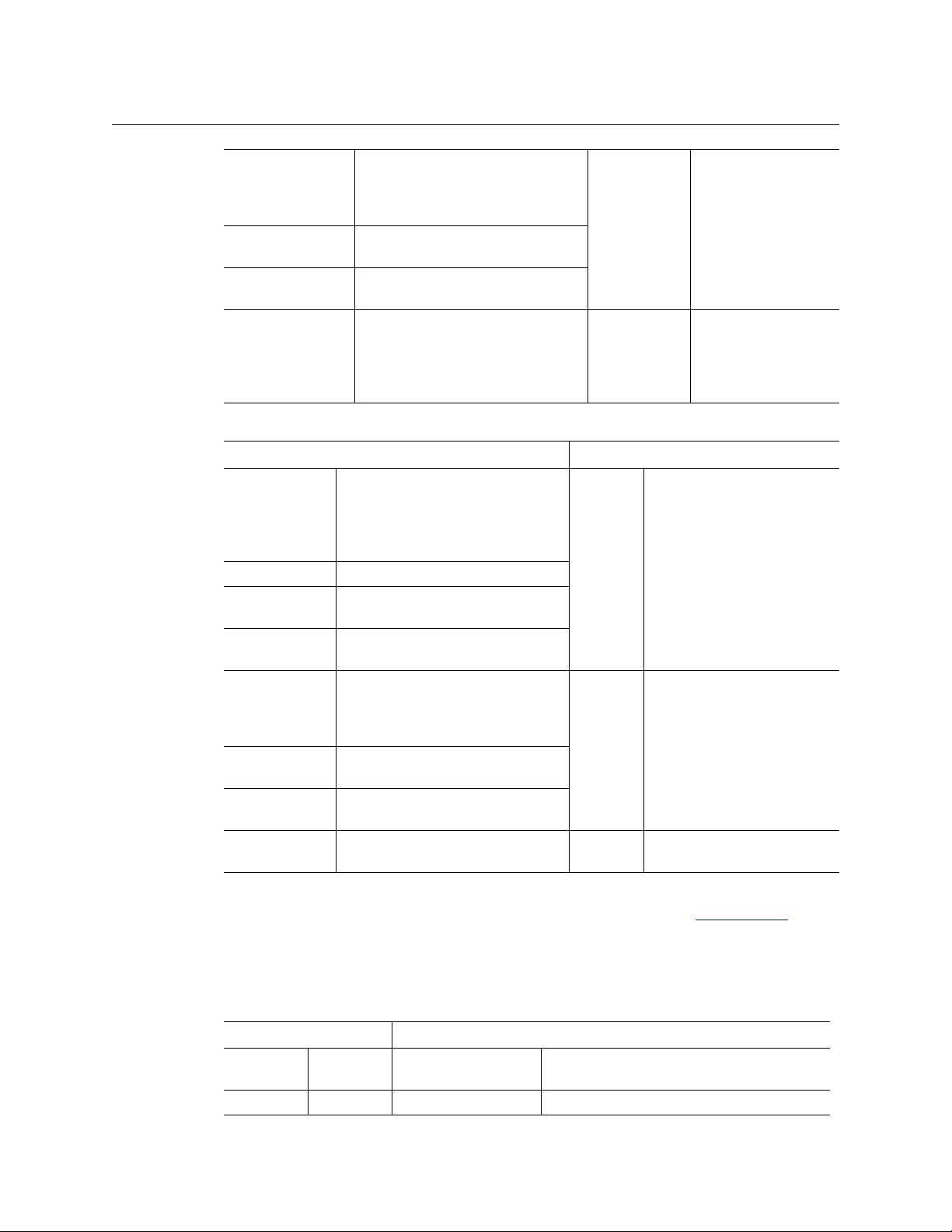
CR Series products include 1RU and 2RU routers, control panels, and “remote panel modules.”
The CR Series includes video and audio routers in several formats, and machine control routers.
These are the 1RU compact routers and matching control panels:
1RU Routers Corresponding 1RU Control Panel
CR0808-3Gig
CR0808-HD
CR0808-SD
CR0808-AES
CR0808-HD-NR
CR0808-SD-NR
CR0808-AA
CR0808-AV
CR1616-3Gig
CR1616-HD
CR1616-SD
CR1616-AES
CR16-PR 16-port machine control
CR1616-HD-NR
CR1616-SD-NR
CR1616-AA
CR1616-AV
. . . . . . . . . . . . . . . . . . . . . . . . . . . . . . . . . . . . . . . . . . . . . . . . . . . . . . . . . . . . . . . . . . . . . . . . . . . . . . . . . . 25
8×8, “3Gig” digital video
8×8, high definition digital video
8×8, standard definition digital video
8×8, AES3id digital audio
8×8, HD video, non-reclocking
8×8, SD video, non-reclocking
8×8, analog audio
8×8, analog video
16×16, “3Gig” digital video
16×16, high definition digital video
16×16, standard definition digital
video
16×16, AES3id digital audio
16×16, HD video, non-reclocking
16×16, SD video, non-reclocking
16×16, analog audio
16×16, analog video
CP0808 8×8, with 6 function
buttons
CP1616 16×16, with 6 function
buttons
3
Page 16
Introduction
Overview
CR1604-3Gig
CR1604-HD
CR1604-SD
CR1604-AES
CR1604-HD-NR
CR1604-SD-NR
CR1604-AA
CR1604-AV
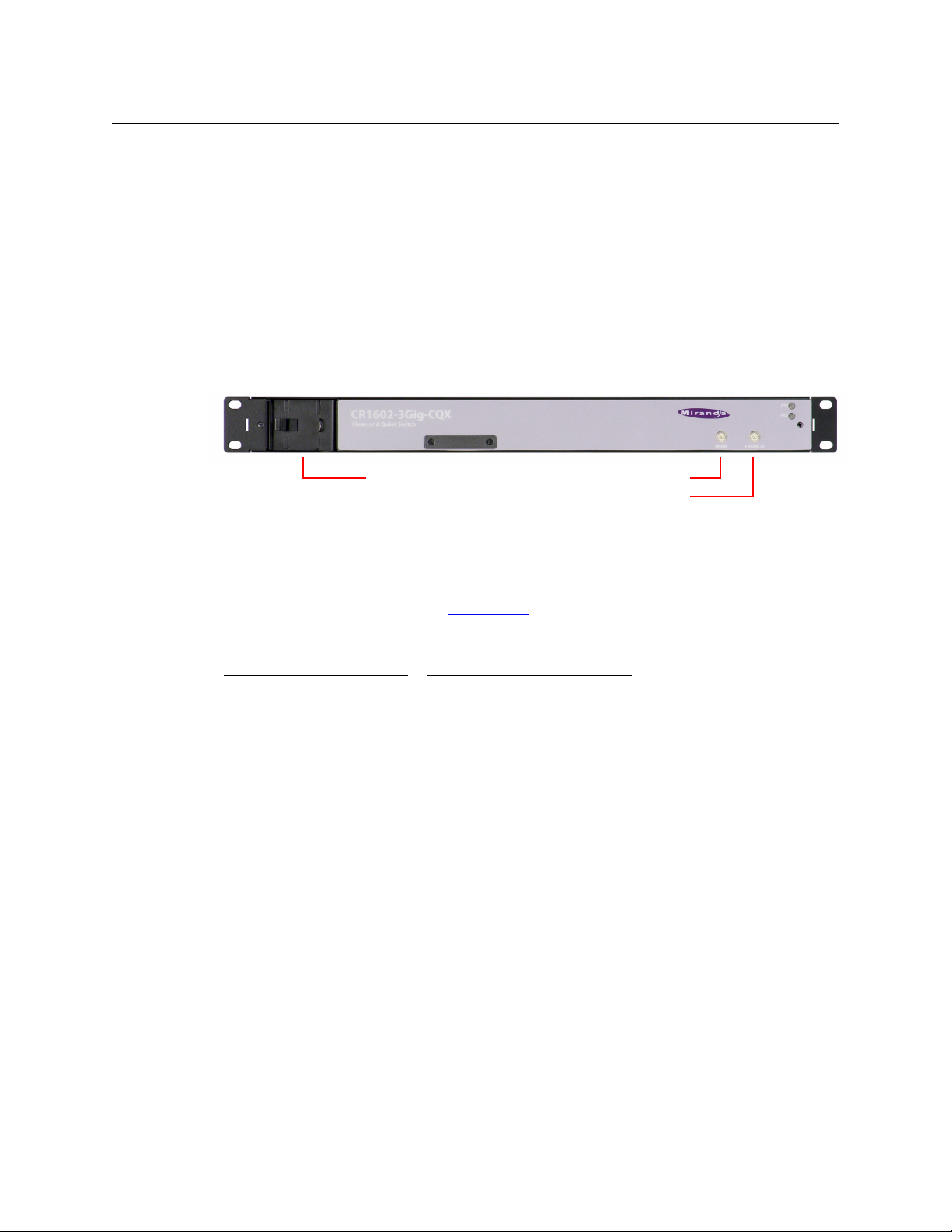
CR1602-3Gig-CQX
CR1602-HD-CQX
CR1602-SD-CQX
16×4, “3Gig” digital video
16×4, high definition digital video
16×4, standard definition digital video
16×4, AES3id digital audio
16×4, HD video, non-reclocking
16×4, SD video, non-reclocking
16×4, analog audio
16×4, analog video
16×2, “3Gig” digital video
16×2, high definition digital video
16×2, standard definition digital video
CP1604
CP1602
CP1602-CQX 16 × (2 + 6), with 4 tran-
16×4, with 6 function
buttons
16×2, with 6 function
buttons
sition type buttons, 3
transition rate buttons,
and 7 function buttons
(5 undefined).
These are the 2RU compact routers and matching control panels:
2RU Routers Corresponding 2RU Control Panel
CR3232-3Gig
CR3232-HD
CR3232-SD
CR3232-AES
CR32-PR 32-port machine control
CR3232-HD-NR
CR3232-SD-NR
CR3232-AA
CR3232-AV
CR3204-3Gig
CR3204-HD
CR3204-SD
CR3204-AES
CR3204-HD-NR
CR3204-SD-NR
CR3204-AA
CR3204-AV
CR6464-3Gig
CR6464-AES
32×32, “3Gig” digital video
32×32, high definition digital video
32×32, standard definition digital
video
32×32, AES3id digital audio
32×32, HD video, non-reclocking
32×32, SD video, non-reclocking
32×32, analog audio
32×32, analog video
32×4, “3Gig” digital video
32×4, high definition digital video
32×4, standard definition digital video
32×4, AES3id digital audio
32×4, HD video, non-reclocking
32×4, SD video, non-reclocking
32×4, analog audio
32×4, analog video
64×64 video router
64×64 AES3id router
CP3232 32×32, with 12 function buttons
CP3204 32×4, with 12 function buttons
CP6464 64×64, with 12 function buttons
The CP3201 (a 1RU panel) is special case not listed in the tables above: it controls 32 sources and
1 destination. It does not “correspond” to any router and is used only in a CRSC Network
. (See
page 75.)
The CR6400 family products (the CR6464-3Gig, CR6464-AES, and the CP6464) are designed to
work together but they do interoperate with other routers and panels in the CR Series.
These are the remote panel modules:
Remote Panel Modules Corresponding Control Panel
RP16 1RU CP1616, CP1604,
CP1602, CP3201
RP32 2RU CP3232, CP3204 32×32, 32×4 with 12 function buttons.
16×16, 16×4, 16×2, with 6 function buttons.
(The CP3201 is a 1RU panel.)
4
Page 17

CR Series
User’s Guide
Routers
The 16×16 routers can switch any of 16 inputs to any of 16 outputs and the 32×32 routers can
switch any of 32 inputs to any of 32 outputs. The 8×8 routers switch 8 inputs to 8 outputs. The
16×4 routers switch 16 inputs to 4 outputs. The 32×4 routers switch 32 inputs to 4 outputs.
Machine Control Routers
With the exception of the machine control routers (CR16-PR and CR32-PR), all the compact
routers are X/Y routers having n × m crosspoint matrices. An input can be routed to any or all of
the outputs.
The machine control routers (also called port routers) are point-to-point routers. An input can be
connected to at most one output. (The connections are RS-422 and bidirectional, typically with
commands in one direction and responses in the other direction.)
“Clean and Quiet” Routers
Each of the 3 “clean and quiet” (CQX) router models routes 16 inputs to 2 “clean and quiet”
outputs or to 6 auxiliary (normal) outputs. For the clean and quiet outputs, the router performs
smooth transitions. The transitions are governed by transition type and transition rate, selectable on the CP1602-CQX control panel. The CQX routers also provide 2 bypass inputs. The 2
clean and quiet outputs switch to the bypass inputs if the router loses power. There are no 2RU
clean and quiet routers at present. The CQX routers also provide a GPIO connector, supporting
16 inputs and 4 outputs. The inputs each select one of the video inputs for CQ output 1 and the
outputs signal alarms and status. See GPIO Connections for CQX Digital Video Routers
page 129 for details.
on
CR6400 Routers
The CR6400 family is a unique subset of the Grass Valley’s CR series of compact routers: the
family’s routers have a larger switching matrix (64×64) and modular construction. The family
includes two routers and a control panel.
• CR6464-3Gig — a 2RU 64×64 video router
• CR6464-AES — a 2RU 64×64 AES router
• CP6464 — a 2RU 64×64 control panel
The CR6400 routers have removable control cards, removable crosspoint cards, and a removable
fan tray. Because they are removable, they are field-serviceable.
Each router has 4 removable I/O cards. If a router is populated with one or more AES cards, it is
considered a CR6464-AES. If a router is populated with one or more 3Gig cards, it is considered a
CR6464-3Gig. If a router has no I/O cards, it is considered to be of “undefined” type.
The CR6400 family products work together may be mixed (on the same subnet) with other CR
Series routers and panels.
Control Panels
A CR Series control panel mounts on the front of a router or on the front of a remote panel
module and provides direct visual and tactile control of the router or routers connected to the
remote panel module. (You can install or uninstall one easily in a few seconds.) However, any of
5
Page 18

Introduction
Overview
the routers can also operate without a control panel, under network control or through
automation.
The CP3201 is special case: it is a 1 RU panel that controls 32 sources and 1 destination. It does
not mount on the front of a router and is used only in a CRSC Network
The CP1602-CQX is also a special case: it is a 1RU control panel used in conjunction with any of
the CQX routers. This panel has 16 source buttons, 2 “clean and quiet” destination buttons, 6
auxiliary destination buttons, 4 transition type buttons, 3 transition rate buttons, and 7 function
buttons (5 undefined).
The CP6464 mounts on CR6400 routers and controls the CR6400 directly. The CP6464 can also
mount on an RP32 (a 2RU remote panel module) and control a network of compact routers.
. (See page 75.)
Remote Panel Modules
A “remote panel module” is a device that sends control messages to a network of routers (and
receives status messages from the routers in the network). A remote panel module receives take
and lock commands from an attached control panel and must have a control panel attached to
be useful. We say the module is “remote” because it and its control panel can be located apart
from the routers (from a few inches to several hundred meters, subject to cable limitations).
There are two remote panel modules available:
• RP16 (1RU)
• RP32 (2RU)
A remote panel module can be configured to operate (with its mounted control panel) as either
(1) a CRSC remote panel or (2) an NV9000 panel in a system controlled by an NV9000 router
control system.
When it is set up for use as a CRSC panel, it is configured in CRSC. When it is set up for use as an
NV9000 panel, it must be configured in NV9000-SE Utilities.
CRSC is the Compact Router System Configurator. See CRSC on page 45 for information.
Please also refer to the NV9000-SE Utilities User’s Guide.
Usage
There are several different ways to use compact routers:
• A single stand-alone router with a “captive” control panel or with automation.
• A network of stand-alone routers, possibly with remote panels, possibly with captive panels,
and with or without automation.
• A CRSC network of routers and remote panels with or without automation. Here, the panels
and routers are configured using CRSC.
• A network of routers under an NV9000 router control system.
• A single stand-alone CQX router with a “captive” CQX control panel or with automation.
• A CQX router with a remote CQX control panel.
A captive panel is one attached directly to a router. A remote panel is one mounted on a
remote panel module.
Automation (control of the routers through their serial ports) is left to the customer.
6
Page 19
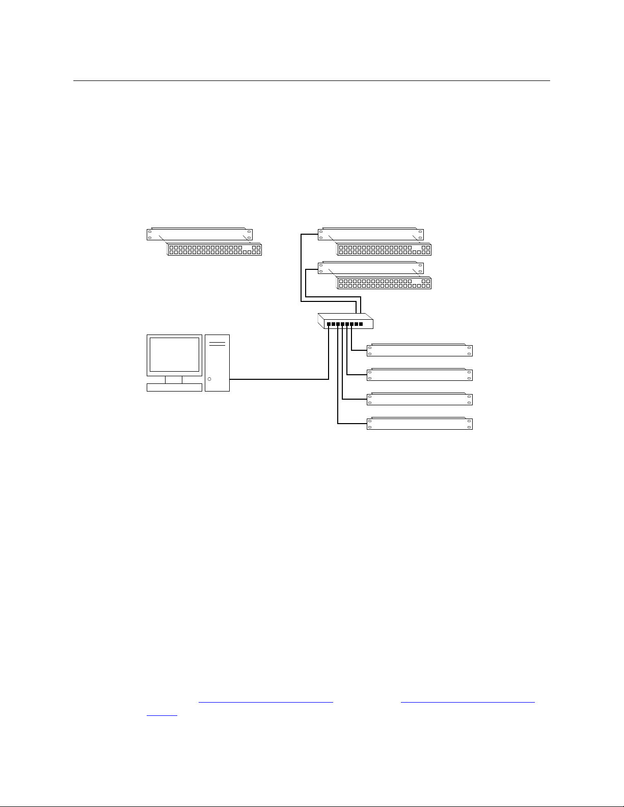
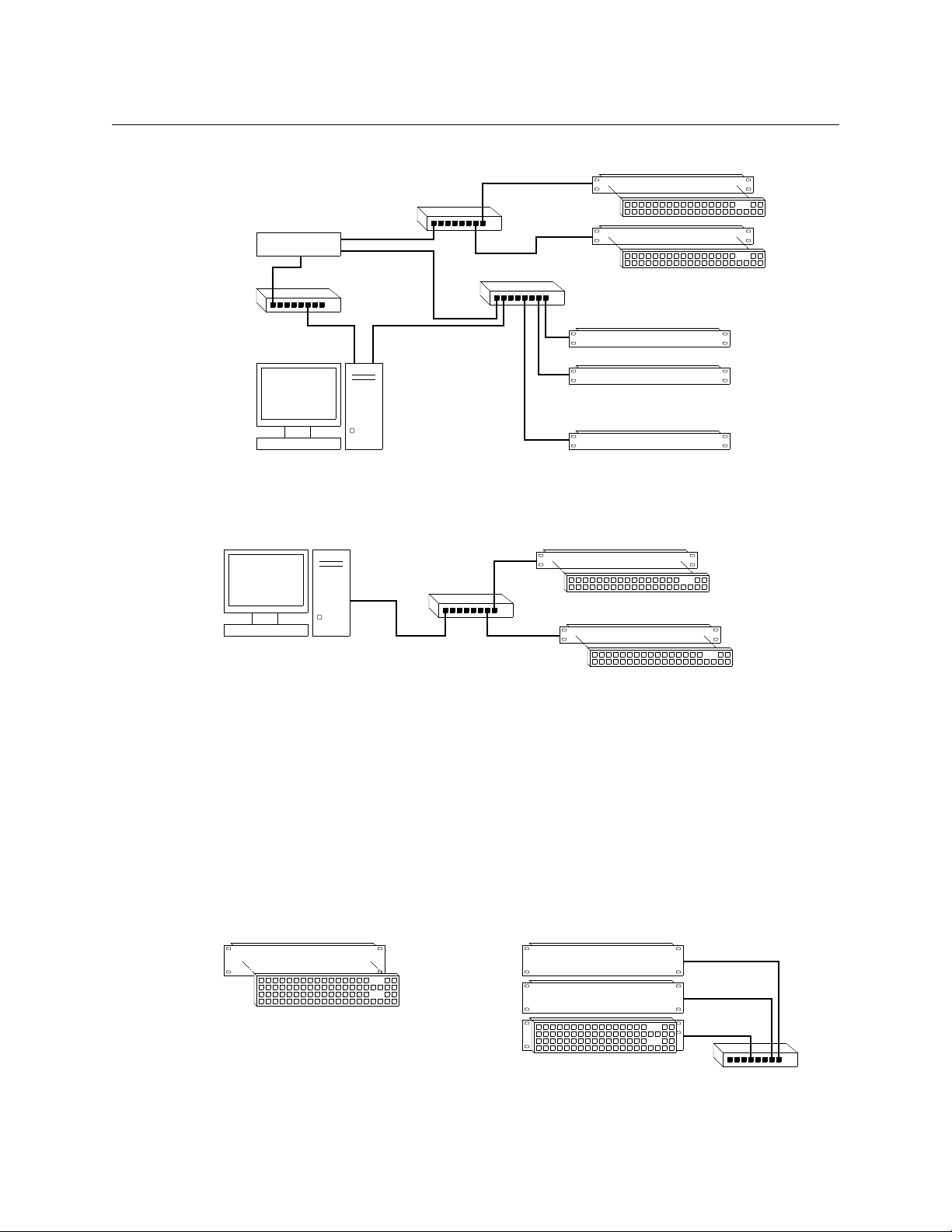
CR Series
Standalone Router and
“Captive” Control Panel
Networked Routers
with Remote Panels
Remote Panel 1
Router 1
Router 2
Router 3
Router 4
Remote Panel 2
Ethernet Switch
PC
User’s Guide
Routers and remote panel modules come from the factory ready for stand-alone operation. If
they are to be used either in a CRSC network or in an NV9000 network, they must be configured
for such use. Once configured, they must be reset if they are to work in stand-alone mode.
A remote panel module must be configured either for a CRSC network, an NV9000 network, or
stand-alone mode. These configuration modes are not compatible.
Stand-Alone Routers
Figure 2-1 compares a stand-alone router with a captive panel to a stand-alone router network
with remote panel modules:
Fig. 2-1: Standalone Router vs. a Network of Routers
CRSC Network
A CRSC network has the same topology as a stand-alone network (shown in Figure 2-1), except
(1) the routers and remote panel modules have been configured under CRSC which provides a
more elegant solution to system design.
CRSC networks do support the use of CR6400 routers and panels.
NV9000 Network
An NV9000 network supports a larger number of routers. Commands issue from the remote
panels to the NV9000 which then dispatches the instructions to the routers. The routers return
status to the NV9000 which in turn relays the status to the remote panels.
An NV9000 system can also receive commands from many other control panel types.
CR Series routers can be used with an NV9000 router control system. The NV9000 system
extends the capabilities of the compact routers.
An NV9000 network is constructed and operated according to the requirements of the NV9000
router control system. Configuration and control of the routers is entirely within the scope of
NV9000-SE Utilities, although you can use CRSC to designate the IP addresses of the compact
routers. See NV9000 Router Control Systems
System (page 179).
(page 178) and Compact Routers in an NV9000
7
Page 20
Introduction
Remote Panel 1
Router 1
Router 2
Router n
Remote Panel 2
Config
PC
NV9000
P/R Net 2
P/R Net 1
House Net
• • •
• • •
Ethernet
Ethernet
Config
PC
Ethernet
CQX Router
Local CQX Panel
Remote CQX Panel
Single Standalone Router and
“Captive” Control Panel
Multiple Standalone Routers
and “Captive” Control Panel
Ethernet
Overview
Figure 2-2 shows a sample NV9000 network, one of several possible topologies:
Fig. 2-2: NV9000 Network of Routers
CQX Networks
Figure 2-3 shows the ways a “clean and quiet” router can be connected:
Fig. 2-3: CQX Network
At present, the CQX connections are limited. One CQX router with a local (or captive) CQX panel
or a remote CQX panel (or both) can exist on any subnet. (You can have more than one subnet,
however.)
At present there is little to configure other than the IP address of the router (and possibly the
remote panel module).
CR6400 Stand-Alone Networks
A CR6400 router can operate in stand-alone mode (also known as “default” mode) either as a
single router or in a small network.
Figure 2-4 compares a stand-alone CR6400 router with a captive panel to a stand-alone router
network with remote panel modules:
8
Fig. 2-4: CR6400 Usage
Page 21
CR Series
User’s Guide
Up to 4 CR6400 routers may be controlled with a single CP6464.
Software
CRSC (Compact Router System Configurator) is a configuration and monitoring tool for compact
routers and remote panels. Refer to the CRSC User’s Guide for details.
Benefits
The CR Series Compact Routers offer these benefits:
• Grass Valley performance and quality.
• Very simple operation.
• Low cost.
• Small form factor.
• Easy migration to larger systems.
The Routers
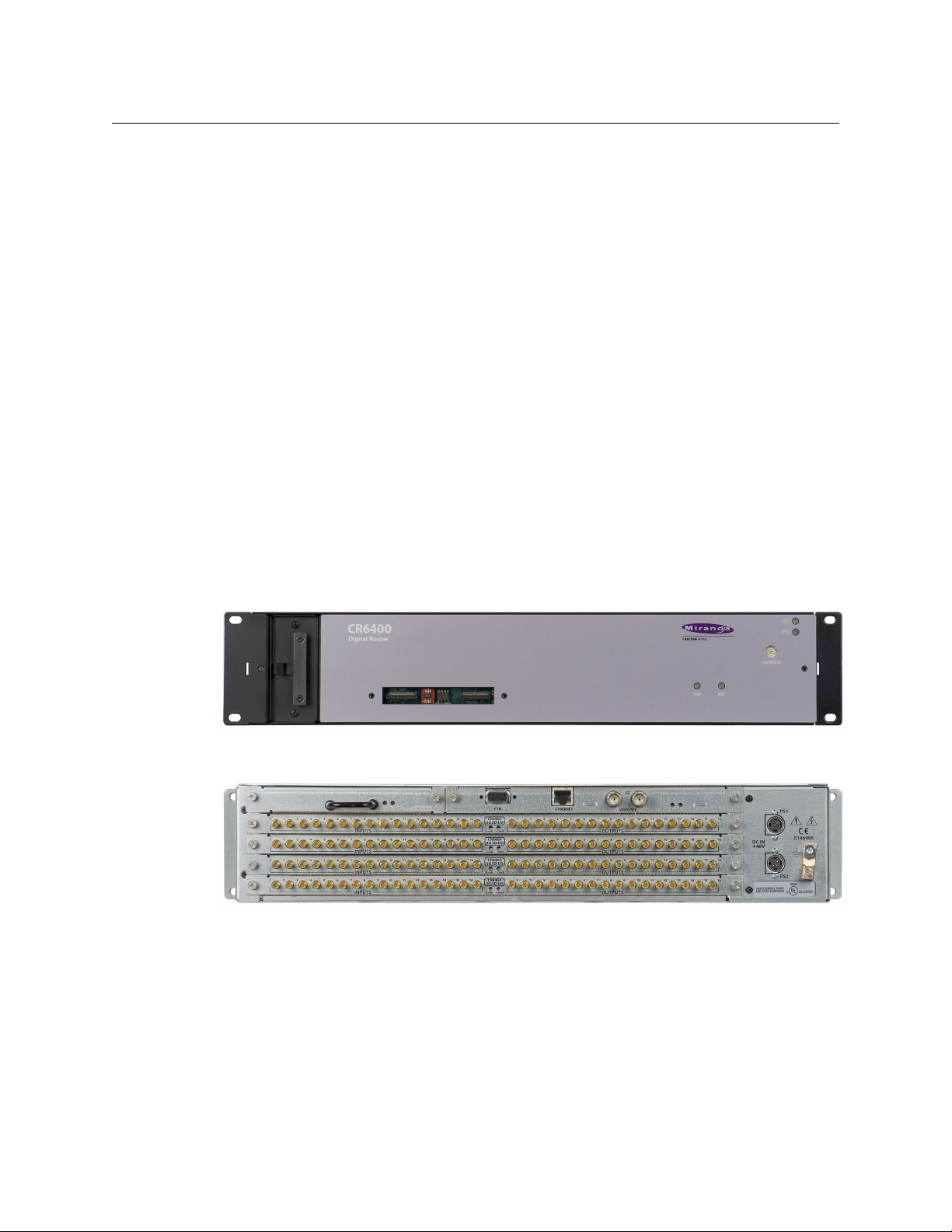
CR6400 Routers
The CR6400 routers are 2RU and about 10” (254 mm) deep. The 2 models in the family are visually identical, except for the legend on the I/O cards (3Gig or AES) at the rear.
Figures 2-7 and 2-6 show front and rear views of the CR6400 routers.
Fig. 2-5: Front View of the CR6400 Digital Router
Fig. 2-6: Rear View of the CR6400 Router (CR6464-3Gig shown)
Other CR Series Routers
The routers are slim (35–57mm or 1.38”–2.25”) and mechanically similar, differing principally in
the number and type of connectors, and of course, in the signal type supported. The fronts of all
the 1RU routers are the same except for their legends and the fronts of all the 2RU routers are
the same except for their legends.
The 3Gig, HD, SD, AES, and analog video routers have BNC connectors. The analog audio routers
have DB25 connectors (and fans). The machine control routers have RJ-45 connectors.
9
Page 22

Introduction
Overview
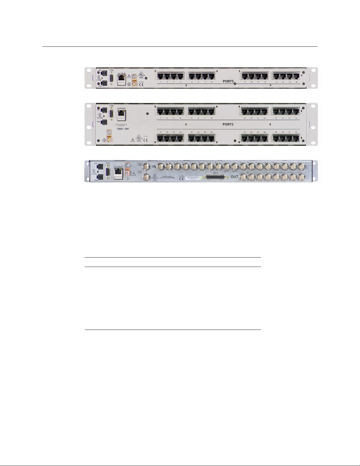
Figures 2-7 through 2-17 show front and rear views of the routers.
Fig. 2-7: Front View of the CR1616-SD Digital Video Router
Fig. 2-8: Rear View of the 16×16 3Gig, HD, SD, or AES Routers
Fig. 2-9: Front View of the CR3232-HD Digital Video Router
Fig. 2-10: Rear View of the 32×32 3Gig, HD, SD, or AES Routers
Fig. 2-11: Rear View of the CR1616-AV Analog Video Router
Fig. 2-12: Rear View of the CR3232-AV Analog Video Router
Fig. 2-13: Rear View of the CR1616-AA Analog Audio Router
10
Page 23
CR Series
User’s Guide
Fig. 2-14: Rear View of the CR3232-AA Analog Audio Router
Fig. 2-15: Rear View of the CR16-PR Machine Control Router
Fig. 2-16: Rear View of the CR32-PR Machine Control Router
Fig. 2-17: Rear View of the 16×2 CQX Routers (3Gig, HD, or SD)
Some routers (e.g., the CR3204-AA or the CR0808-3Gig) have fewer input or output connectors
than shown here.
All compact routers save their state in non-volatile memory. Thus, if a power loss occurs, a router
can recover almost instantly. All compact routers require a few seconds to initialize.
All compact routers have an serial port (DE9, RS-422 or RS-485).
All compact routers, including CR6400 routers, but not machine control routers, accept these
video reference rates:
Composite HD Tri-level
525i / 59.94
(NTSC)
625i / 50
(PAL)
720p / 23.98
720p / 24
720p / 25
720p / 29.97
720p / 30
720p / 50
720p / 59.94
720p / 60
1080i / 47.95
1080i / 48
1080i / 50
1080i / 59.94
1080i / 60
1080p / 23.98
1080p / 24
1080p / 25
1080p / 29.97
1080p / 30
1080p / 50
1080p / 59.94
1080p / 60
Machine control routers do not receive video reference signals.
11
Page 24
Introduction
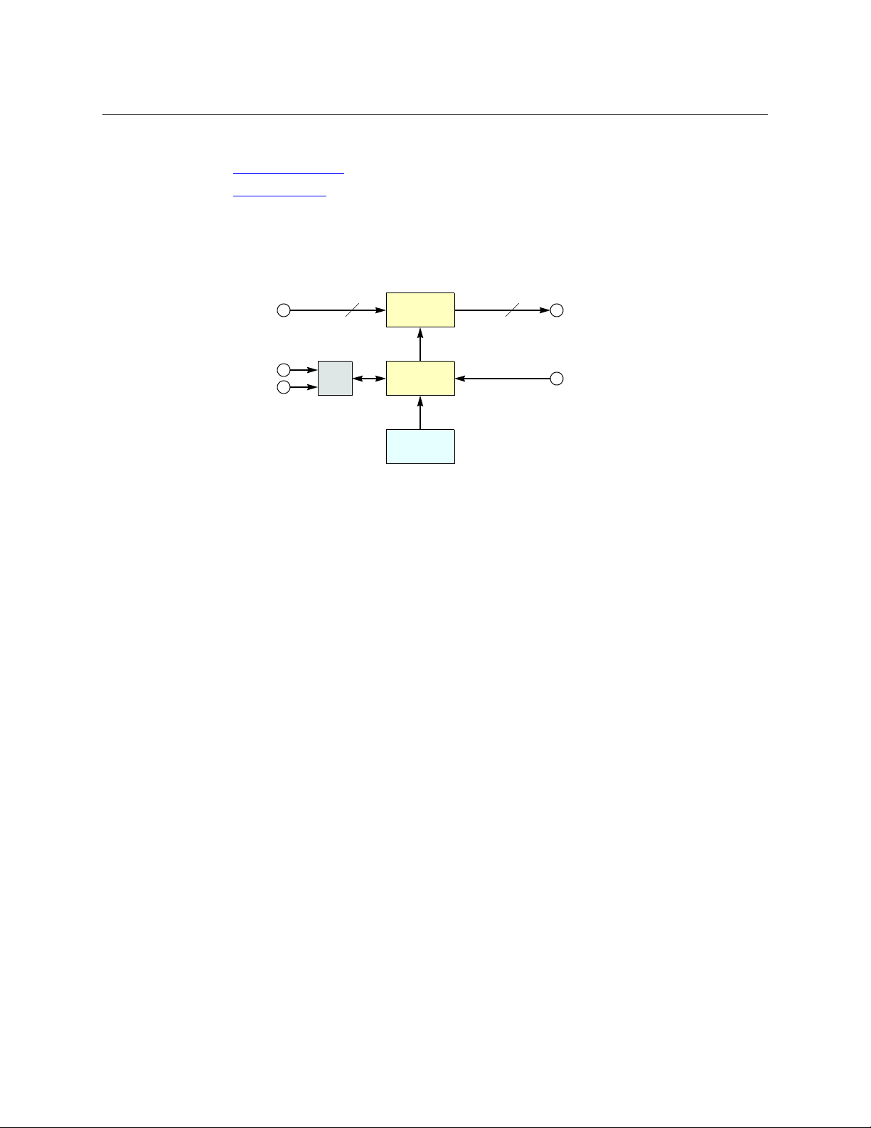
M N
μP Logic
Inputs
(Equalized)
Outputs
(Reclocked)
Crosspoint
Switch
Control
Panel
Video Refer-
ence
Serial
Ethernet
(optional)
M = 8, 16, or 32
N = 4, 8, 16, or 32
Overview
Digital Video Routers
(See CQX Video Routers on page 13 for a discussion of the CQX routers.)
(See CR6400 Routers
Other digital video routers are discussed here.
The 1RU digital video routers have 16×16, 16×4, or 8×8 crosspoint matrices, depending on the
model. The 2RU digital video routers have either 32×32 or 32×4 crosspoint matrices.
Figure 2-18 shows a simplified view of the digital video router:
Fig. 2-18: Block Diagram of the Digital Video Router
on page 16 for a discussion of the CR6400 routers.)
The video routers perform input equalization and, except for the -NR models, perform
reclocking of outputs. The -NR models do not perform reclocking. Router outputs are switched
in sync with an external video reference if it is present.
All digital video routers accept bi-level or tri-level video references (sync) and switch according
to SMPTE RP168-2002.
3Gig and HD Video Routers
All of the “3Gig” routers support 2.966 Gb/s, and 2.97Gb/s video rates as well as a number of HD
bit rates and formats. The 3Gig routers reclock at 270 Mb/s, 1.483Gb/s, 1.485Gb/s, 2.966Gb/s,
and 2.97Gb/s. The 3Gig routers bypass re-clocking for other rates. Video references must be
nominally 800mV p-p and bi-level or tri-level in nature.
All of the “HD” routers are SWB (super wide band) routers: they support a wide range of SD and
HD bit rates and formats, from 10Mbps to 1.5Gbps. With the exception of the -NR routers, the
HD routers reclock at 143, 177, 270, 360, and 540 Mb/s and 1.483 and 1.485 Gb/s and bypass reclocking for other rates. Video references must be nominally 800mV p-p and bi-level or tri-level
in nature. The HD routers support DVB-ASI signals.
SD Video Routers
All of the “SD” routers support a wide range of SD serial data rates from 10Mb/s to 540MB/s.
With the exception of the -NR routers, the SD routers reclock at 143, 177, 270, 360, and 540Mb/s.
The SD routers support DVB-ASI signals.
NR Video Routers
The HD and SD routers are available in non-reclocking models, such as the CR1616-HD-NR and
CR3204-SD-NR. These models are less expensive than the models that have reclocking circuitry
and work well with relatively noise-free signals. The reclocking models give better performance
in noisy environments.
12
Page 25
CR Series
User’s Guide
Digital Video Formats
The digital video routers (other than CQX routers) perform video processing for these rates:
Video Format Bit Rate Remarks
1080p, 60Hz 2.97Gb/s 3Gig
1080p, 59.94Hz 2.96 Gb/s
1080p, 30Hz 2.97Gb/s
1080p, 29.97Hz 2.96 Gb/s
1080p, 25Hz 2.97Gb/s
1080p, 24Hz 2.97Gb/s
1080p, 23.98Hz 2.96 Gb/s
1080i, 60Hz 1.485Gb/s HD
1080i, 59.94Hz 1.483Gb/s
1080i, 50Hz 1.485Gb/s
1080psf, 30Hz 1.485Gb/s
1080psf, 29.97Hz 1.483Gb/s
1080psf, 24 Hz 1.485 Gb/s
1080psf, 23.98 Hz 1.483 Gb/s
720p, 60Hz 1.485Gb/s
720p, 59.94Hz 1.483 Gb/s
720p, 50Hz 1.485Gb/s
720p, 30Hz 1.485Gb/s
720p, 29.97Hz 1.483 Gb/s
720p, 25Hz 1.485Gb/s
720p, 24Hz 1.485Gb/s
720p, 23.98Hz 1.483 Gb/s
625i, 50Hz 270Mb/s SD
525i, 59.94Hz 270Mb/s
The 3Gig routers can receive all rates listed for HD and SD. The HD routers can also receive video
at SD rates.
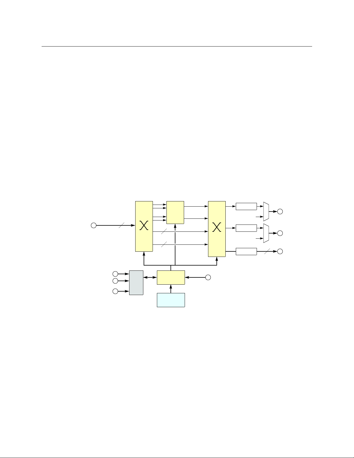
CQX Video Routers
These 1RU “clean and quiet” video routers switch 16 inputs to 2 “clean and quiet” outputs and 6
auxiliary outputs.
The CQX routers have two crosspoint matrices. The first crosspoint routes 16 normal inputs
either to an internal mixer or to the second crosspoint matrix.
The mixer has 2 channels. Each channel mixes two inputs and produces an internal “clean”
output. One of the inputs is the signal previously routed to that channel and the other input is
the signal that will be routed to that channel. The mixer produces the transition between the
previous input and the next input according to the transition type and transition rate currently
selected (at a control panel) for the router.
13
Page 26
Introduction
non-sync
bypass
clean 2
clean 1
Reclock
Em. Bypass 2
CQX 2
6
6
μP Logic
Inputs
(Equalized)
Aux Outputs
Control
Panel
Video Reference
Serial
Ethernet
(optional)
16
Mix 1
Mix 2
Reclock
Em. Bypass 1
CQX 1
Reclock
GPIO
2
Overview
For the SD and HD CQX routers, each input supports video plus 16 embedded audio channels.
The mixer transitions both the video and the audio without artifacts.
The 3Gig router supports both level A and level B of the SMPTE 425M standard. The mixer transitions signals of level A, at 1080p, video and audio without artifacts. It handles level B
1080i signals in one stream
— somewhat differently. It mixes the 16 audio channels of “link A”
— two
(from the two inputs) but passes the 16 audio channels of link B (from the two inputs) through
to the output unmixed. “Link B” will undergo a cut transition with possible audio artifacts.
Although audio for Link B is not processed and undergoes a cut transition, video for Link B is
mixed according to the transition type and rate selected on the CQX control panel.
The 3Gig routers do not accept level B’s 2×720p signals at present.
The second crosspoint matrix receives internal signals and produces the CQX outputs 1 and 2
and the 6 auxiliary outputs (which are normal outputs). A multiplexer selects either the clean
output or the emergency bypass input. The emergency bypass input is selected only when
power fails. (The multiplexer is controlled by a relay that switches to its relaxed position when
power fails.)
The router has 16 normal input BNCs, 2 bypass input BNCs, 2 CQX output BNCs, and 6 aux
output BNCs.
Figure 2-19 shows a simplified view of the CQX digital video router:
14
Fig. 2-19: Block Diagram of the CQX Digital Video Router
The video routers perform input equalization and perform reclocking of outputs. Router
outputs are switched in sync with an external video reference if it is present. The video reference
also provides sync for embedded audio.
All CQX video routers accept bi-level or tri-level video references (sync) and switch according to
SMPTE RP168-2002.
The CQX video routers also provide a bypass path for non-synchronous input signals. If the two
sources chosen for a clean and quiet switch are not of the same format, are off-rate, are not at
the same frame rate as the video reference, or do not meet the timing window (±3 lines), the
video processor enters non-sync bypass mode where the source signal bypasses the video
processor and goes straight to the outputs. Thus, the clean and quiet output behaves like an aux
output in which there is no video or audio processing
— with no transition processing. Switches
Page 27
CR Series
Recessed Fan unit 16-pos Mode Switch
16-pos Frame ID Switch
User’s Guide
still occur at the specified switchpoint for the video reference, but they will not be “clean and
quiet.”
However, if there is no video reference present, the CQX does the cut to the new source as soon
as it receives the command from the control panel and does not wait for the switchpoint.
Where one or both of the sources is off-rate or at a frame rate different from that of the video
reference, the output will bypass the video processor.
If a clean and quiet output is in a non-sync state but conditions change so that a clean switch is
possible, the processor waits for one frame of video before switching to processed video to
ensure that the processed video has enough time to pass through the video processing path.
The CQX video routers have a removable fan unit. The fan unit is not visible when a CQX panel is
mounted on the router.
Fig. 2-20: Front View of the CQX Video Router
Customers should have no reason to remove the fan unit.
The CQX video routers have a “mode” switch in addition to the 16-position frame ID switch. Both
are 16-position rotary switches that turn with a small screwdriver. The “mode” switch configures
the video format of the router. See CQX Routers
on page 81 for details.
Set the rotary switch to a position in the range 0–9, A, B, C, or D, according to this table:
Setting Format Setting Format
0 1080i, 59.94 or 60
1080p, 29.97 or 30
1080psf, 29.97 or 30
1 1080i, 50
1080p, 25
1080psf, 25
2 525i, 59.94 C 720p, 23.98 or 24
3 625i, 50 D 1080p, 23.98 or 24,
4 720p, 59.94 or 60
5 720p, 50 E reserved
6 1080p, 59.94 or 60
7 1080p, 50
8 2 × 1080i, 59.94 or 60
9 2 × 1080i, 50
A 720p, 29.97 or 30
B 720p, 25
1080psf, 23.98 or 24
F reserved
Switch positions 6 and 7
correspond to video according to SMPTE 425 level A.
Switch positions 8 and 9
correspond to video according to SMPTE 425 level B.
The default is 1080i, 59.94 Hz (switch setting 0). Positions E and F are not valid positions.
Where a switch setting supports multiple formats, the format is governed by the video reference
applied to the router and must be compatible with that reference format.
The CQX routers enter non-sync bypass mode for signals at other rates.
When a control panel is mounted on a router or remote panel module, it conceals the rotary
switch. You must remove the control panel when you are setting the rotary switch.
Every time you make a switch change, power-cycle the router or remote panel module.
15
Page 28
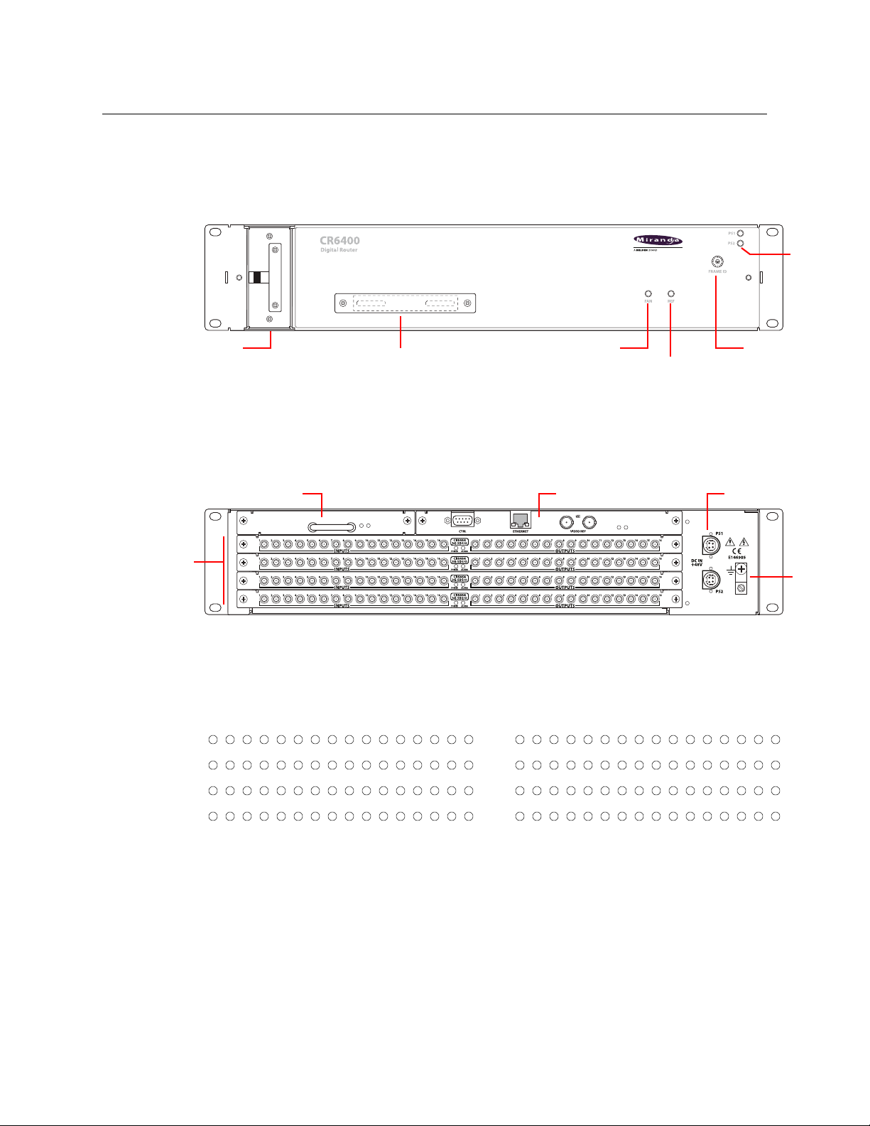
Introduction
Power
LEDs
Rotary Switch
Reference LED
Fan LED
Connector Cover Plate
(Removable) Fan Unit
Control CardCrosspoint Card
I/O Card
Slots (4) Ground
Lug
Power (2)
123456789 10111213 14 15 16 123456789 10111213 14 15 16
Input Output
17 18 19 20 21 22 23 24 25 26 27 28 29 30 31 32
33 34 35 36 37 38 39 40 41 42 43 44 45 46 47 48
49 50 51 52 53 54 55 56 57 58 59 60 61 62 63 64
17 18 19 20 21 22 23 24 25 26 27 28 29 30 31 32
33 34 35 36 37 38 39 40 41 42 43 44 45 46 47 48
49 50 51 52 53 54 55 56 57 58 59 60 61 62 63 64
Overview
CR6400 Routers
Note: the CR6400 Family Users Guide offers complete detail.
The CR Series routers are 2RU routers. They are about 10” deep to accommodate removable I/O
cards. This is a front view of the router:
The CR6464-3Gig and the CR6464-AES routers have the same features at the front. The two
routers are distinguished, at the rear, by the labeling on their I/O cards.
The router’s fan module is removable through the front of the router.
At the rear, the CR Series routers have 4 slots for removable I/O cards, and slots for a crosspoint
card and a control card (also called a CPU card).
Each I/O card has 32 ports. There are 16 input ports on the left (as you face the rear of the router)
and 16 outputs on the right. The connectors for both the 3Gig card and the AES card are DIN 1.0/
2.3 connectors (which we usually call “coax” connectors).
The port numbering at the rear of the CR6400 routers is simple:
It is 1–64, top-to-bottom, on the left for inputs and 1–64, top-to-bottom, on the right for
outputs.
At this revision, the router must contain only 3Gig cards or only AES cards. It may contain from 1
to 4 cards. If the router is populated with 3Gig cards, the router is considered a CR6464-3Gig and
switches video. If the router is populated with AES cards, the router is considered a CR6464-AES
and switches audio. A router having no cards is considered to be of “undefined” type.
16
Page 29
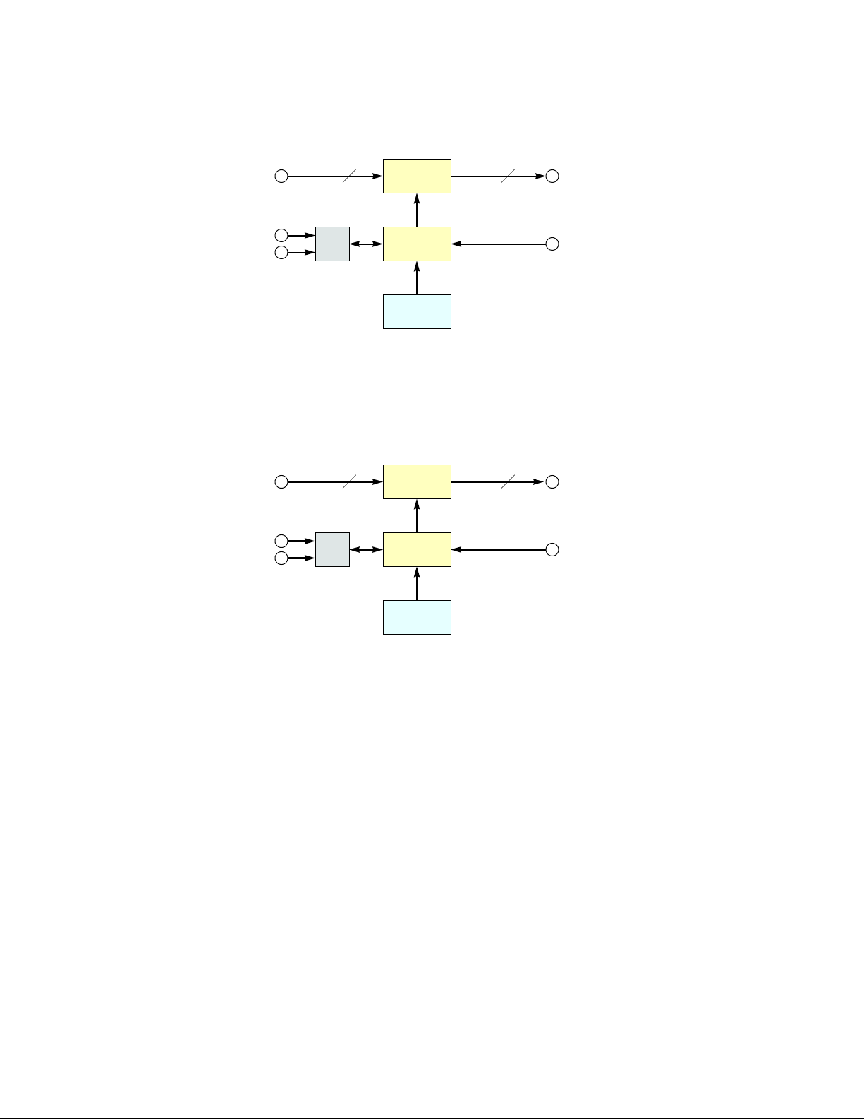
CR Series
64 64
μP Logic
Inputs
(Equalized)
Outputs
(Reclocked)
Crosspoint
Switch
Control
Panel
Video
Reference
Serial
Ethernet
(optional)
M N
μP Logic
Inputs Outputs
Crosspoint
Switch
Control
Panel
Video Refer-
ence
Serial
Ethernet
(optional)
M = 8, 16 or 32
N = 4, 8, 16, or 32
User’s Guide
Figure 2-18 shows a simplified block diagram of a CR Series router:
Fig. 2-21: Block Diagram of the CR Series
Analog Video Routers
The 1RU analog video routers have 16×16, 16×4, or 8×8 crosspoints. The 2RU analog video
routers have either 32×32 or 32×4 crosspoints.
Figure 2-22 shows a simplified view of an analog video router:
Fig. 2-22: Block Diagram of the Analog Video Router
The analog video routers switch NTSC (525i) or PAL (625i) video signals. The router outputs are
switched in sync with an external video reference if it is present.
17
Page 30
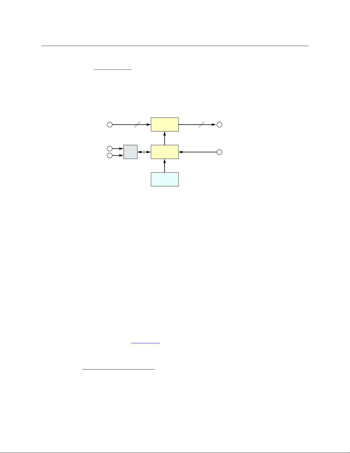
Introduction
M N
μP Logic
Inputs Outputs
Crosspoint
Switch
Control
Panel
Video Refer-
ence
Serial
Ethernet
(optional)
M = 8, 16 or 32
N = 4, 8, 16, or 32
Overview
Digital Audio Routers
(See CR6400 Routers on page 16 for a discussion of the CR6400 family’s AES router. This section
does not apply to the CR6400 family.)
Other digital audio routers are discussed here.
The 1RU AES routers have 16×16, 16×4, or 8×8 crosspoints. The 2RU AES routers have either
32×32 or 32×4 (stereo) crosspoints.
Figure 2-23 is a simplified view of an AES router:
Fig. 2-23: Block Diagram of the AES Router
If a video reference is present, the router is considered “synchronous” and regenerates output at
48kHz (nominally). The routers also perform a certain amount of signal processing if the input is
synchronous. If a video reference is not present, the router is asynchronous and passes input
signals straight through without any processing.
In synchronous mode, the router can perform mono routing, in which case, the maximum
number of signals is 2N, that is 8, 16, 32, or 64. In asynchronous mode, the router processes AES
stereo pairs.
The “AES” routers switch AES3id audio. The AES routers switch in sync with a video reference if
one is present.
The two AES modes have different functional characteristics:
• Synchronous mode.
This mode is intended for 48kHz input. However, the router accepts input from 32kHz to
192kHz. The router produces AES3id output at 48kHz using adds and drops,
1
as required. If
the input itself is locked to the video reference, no adds or drops occur.
The 16×16 router supports either 16×16 stereo switching or 32×32 mono channel switching
(when controlled by an external control system). The 32×32 router supports either 32×32
stereo switching or 64×64 mono channel switching (when controlled by an external control
system). Refer to AES Routers
on page 181 for more information.
18
1. When the source and output AES streams are not in sync, AES samples arrive at a rate different from the
rate at which they leave the router. Add: when the source is slower than the output, router software occasionally inserts an extra copy of the most recent sample in the output stream until the source and
output are back in sync. Drop: when the source is faster than the output, software occasionally does not
send the sample(s) to the output until the source and output are back in sync again. Adds and drops are
performed on a minute scale, never in large blocks, keeping perceptible distortions to a minimum.
Page 31

CR Series
M N
μP Logic
Inputs Outputs
Crosspoint
Switch
Control
Panel
Video Refer-
ence
Serial
Ethernet
(optional)
M = 8, 16 or 32
N = 4, 8, 16, or 32
User’s Guide
A control panel cannot and does not perform mono switching. It is only in external soft-
ware (CRSC, NV9000, or third-party software) that you can do that and then only when
the router is in synchronous mode (i.e., has a video reference).
• Asynchronous mode.
The router passes the input stream (32kHz–192kHz) transparently to the output with no
audio processing. The output is the same as the input and the output rate is the same as the
input rate.
Because the router does no audio processing, it performs stereo switching only.
AES routers power up in asynchronous mode. If a video reference is present, the router immediately switches to synchronous mode. If no video reference is present, the router stays in
asynchronous mode.
If a video reference is applied at any time after power-up, the router immediately switches from
asynchronous to synchronous mode.
IMPORTANT
When the router is in synchronous mode, and video reference is lost, the router waits 15
minutes (a “grace” period) before reverting to asynchronous mode. If you need to
switch from synchronous mode to asynchronous mode in less than 15 minutes, you can
cycle power to the router with the video reference disconnected.
Analog Audio Routers
The 1RU analog audio routers have 16×16, 16×4, or 8×8 crosspoints. The 2RU analog audio
routers have either 32×32 or 32×4 (stereo) crosspoints. Figure 2-22 shows a simplified view of
the analog video router:
Fig. 2-24: Block Diagram of the Analog Audio Router
The analog audio routers switch analog audio signals. Router outputs are switched in sync with
an external video reference if the reference is present and are switched asynchronously if no
reference is present.
The analog audio router passes input signals transparently to the output with no audio
processing or adjustments.
Although the analog audio routers signals are stereo, the connectors are labeled as if the
signals were mono. A 16×16 router shows inputs and outputs numbered 1–32. A 32×32
router shows inputs and outputs numbered 1–64. An 8×8 router shows inputs and outputs
numbered 1–16.
19
Page 32

Introduction
N
μP Logic
Crosspoint
Switch
Control
Panel
Serial
Ethernet
(optional)
N = 16 or 32
Ports
SRC DST
Compact RouterControlling device
Controlled device
SRC DST
Compact RouterControlled device
Controlling device
Overview
Machine Control Routers
The machine control routers do not have X/Y crosspoints per se, but allow point-to-point
connections. One input may connect to (at most) one output.
The 1RU machine control router has 16 bidirectional serial ports (RJ-45). The 2RU machine
control router has 32. Figure 2-22 shows a simplified view of the machine control router:
Fig. 2-25: Block Diagram of the Machine Control Router
Machine routers channel serial data, typically commands in one direction and responses in the
other direction. Because the connections are bidirectional, a port is both an input and an
output.
The machine control routers are defined as “data reverse” routers. Each port can be configured
as dynamic, master, slave, controlling, or controlled. CRSC is a requirement for configuring the
ports.
The machine control routers support serial communication up to 1Mb/s.
Background Information
A device can be considered a “controlled” device or a “controlling” device.
Above, the source device is a controlling device. A destination can also be the controlling
device:
A controlling device sends commands to a controlled device. The controlled device passes
responses (such as status) back to the controlling device. A source device can be a controlling
device or a controlled device. A destination device can be a controlling device or a controlled
device.
Some external devices must be placed in “remote” mode to work with a port router.
A controlling port is one connected to a controlling device.
A controlled port is one connected to a controlled device.
20
Page 33

CR Series
Panel LockDestination Lock
Level
Selection
User’s Guide
The compact machine control routers operate in “data reverse” mode. This means that in any
connection, the destination device is the controlling device by default. The default can be overridden by port type.
The 5 port types are variations of “controlled” or “controlling”:
Controlling Master Dynamic
Controlled Slave
Controlling or Controlled
These port settings fix the direction of the router port to “controlling” or “controlled.” The port’s
connection for Tx and Rx
operation.
— made during configuration — is static and does not change during
Dynamic
A dynamic port can be a controlling or controlled port depending on whether it is connected to
a master port or slave port. The port’s configuration is dynamic and can change during
operation.
Dynamic ports are typically assigned to VTRs.
Master or Slave
Any dynamic port connected to a “master” port will be changed to a controlled port. A “slave”
port is the opposite of a “master” port: any dynamic port connected to a slave port will be
changed to a controlling port.
The compact router applies logic to the port direction setting when a master port is connected
to a dynamic port. In this case, the machine at the dynamic port is always controlled and the
machine at the master port is always controlling.
Configuration
Configuring the ports of a machine control router requires CRSC.
The Control Panels
Control panels are optional if you have an automation system or a control system.
1RU Panels
The CP1616 control panel has 38 buttons:
Fig. 2-26: Front view of the CP1616 Control Panel
The CP1604 control panel resembles the CP1616, but it has 4 buttons in the lower row on the
left, instead of 16. The CP1602 has 2 buttons in the lower row on the left.
The CP0808 has 2 rows of 8 buttons at the far left.
21
Page 34

Introduction
Panel LockDestination Lock
Transi tion Transi tion
CQ Outputs
Aux Outputs
Inputs (16)
(unused)
Panel LockDestination Lock
Func tion
buttons
Func tion
buttons
Overview
In stand-alone systems, a CP1616 has 16 source selection buttons, 16 destination selection
buttons, the 2 lock buttons shown, and 4 level selection buttons (as shown).
In a CRSC system, all buttons except the lock buttons (shown) are configurable. In an NV9000
system, all buttons are configurable, including the lock buttons.
You can mount a 1RU panel on any 1RU router or remote panel module.
The CP3201 is a 1RU panel that resembles the CP1616, but it has 32 source buttons (in 2 rows of
16) and no destination buttons. The CP3201 cannot be used as a captive panel. Its design
requires a CRSC or NV9000 network.
CQX Panel
The CP1602-CQX is also a 1RU control panel that has 38 buttons:
Fig. 2-27: Front view of the CP1602-CQX Control Panel
The CP1602-CQX control panel has 16 source buttons, 2 CQX destination buttons, 6 auxiliary
destination buttons, 4 transition type buttons, 3 transition rate buttons, and 7 function buttons.
Of the function buttons, 5 are presently disabled, reserved for future use, and two are active. The
active buttons are ‘Destination Lock’ and ‘Panel Lock’.
2RU Panels
CP6464
The CP6464 control panel can be mounted on a CR6400 router and it will control that router
directly. It can also be mounted on a 2RU remote panel module and control the routers in a
CRSC network.
This is the CP6464:
Fig. 2-28: Front view of the CP6464 Control Panel
A CP6464 has an array of 64 general function buttons at the left and 12 general function buttons
at the right.
There are two lock buttons (at the top right):
• Panel Lock. Protects the state of the entire panel.
• Destination Lock. Protects one or more destinations.
22
Page 35

CR Series
Panel LockDestination Lock
Level
selection
Selection
Buttons
Src or Dst
mode
Panel LockDestination Lock
Level
Selection
User’s Guide
When the CP6464 is mounted on a CR6400 router operating in stand-alone mode, the general
function buttons have fixed and predefined functions:
The ‘SRC’ button (at the right) places the panel in source mode, and the operator may select a
source from the array of 64 selection buttons. Similarly, the ‘DST’ button (also at the right) places
the panel in destination mode, and the operator may select a destination from the 64 selection
buttons.
When the panel is mounted on a 2RU remote panel module, controlling the routers in a CRSC
network, the assignment of functions to the buttons is completely configurable. (And in a CRSC
network, the buttons must have been configured if the panel is to function at all.)
Buttons are not labeled at the factory. If you want button legends, you must create your
own. See Button Legends
on page 74.
A panel’s buttons have color: green, amber, or red. Green usually means source and amber
usually means destination. Red is usually a warning of some kind. For instance, the buttons for
locked destinations appear red.
Buttons go high-tally (bright) when selected (pressed) and remain low-tally (dim) when they are
not selected. The function buttons vary in color.
• Unused function buttons are not illuminated.
• The panel lock button, normally low-tally green, goes high tally red when the panel is
locked.
• The destination lock button, normally amber, goes high tally red when the currently selected
destination is locked. When a destination is locked, the destination button goes high tally
red as a warning if you press it. The button color of locked destinations varies with the type
of system.
Other 2RU Panels
The CP3232 control panel has 76 buttons:
Fig. 2-29: Front view of the CP3232 Control Panel
The CP3204 control panel resembles the CP3232, but it has 4 buttons in the lower section on the
left, instead of 32.
23
Page 36

Introduction
Overview
In stand-alone systems, a CP3232 has 32 source selection buttons, 32 destination selection
buttons, the 2 lock buttons shown, and 4 level selection buttons (as shown).
In a CRSC system, all buttons except the lock buttons (shown) are configurable. In an NV9000
system, all buttons are configurable, including the lock buttons.
You can mount a 2RU panel on any 2RU router or remote panel module.
Except under NV9000 control, all control panels have two lock buttons (at the top right):
• Panel Lock. Protects the state of the entire panel.
• Destination Lock. Protects one or more destinations.
Buttons are not labeled at the factory. If you want button legends, you must create your
own. See Button Legends
on page 74.
A panel’s buttons have color: green, amber, red. In a CRSC system, the colors green and amber
have no particular meaning. In a CRSC system, the labels ‘Source’ and ‘Dest’ that you see on the
panel front also have no particular meaning. Any button, regardless of color or position—
except for the lock buttons
— can be a source, a destination, or have any assignable function.
In stand-alone systems, green means source and amber means destination and the labels
‘Source’ and ‘Dest’ do have meaning. The group of buttons labeled ‘Source’ are (green) source
buttons and the group of buttons labeled ‘Dest’ are (amber) destination buttons.
In CRSC or NV9000 systems, the color of the button means little.
Buttons go high-tally (bright) when selected (pressed) and remain low-tally (dim) when they are
not selected.
For all but machine control routers, source buttons represent inputs and destination buttons
represent outputs. For machine control routers, a port is both an input and an output. Source
button n and destination button n both represent port n.
The function buttons vary in color.
• Unused function buttons are not illuminated.
• The panel lock button, normally low-tally green, goes high tally red when the panel is
locked.
• The destination lock button, normally amber, goes high tally red when the currently selected
destination is locked. When a destination is locked, the destination button goes high tally
red as a warning if you press it. The button color of locked destinations varies with the type
of system.
Operating a control panel is usually very simple. See Chapter 5, Operating a Stand-Alone Router
on page 85.
24
The Remote Panel Modules
Like the routers, the remote panel modules are slim (35 mm or 1.38”). Except that they have no
I/O connectors and no video reference connectors, remote panel modules are virtually the same
size and shape as the routers.
Figures 2-30 through 2-33 show front and rear views of the remote panel modules:
Fig. 2-30: Front View of the RP16 Remote Panel Module
Page 37

Fig. 2-31: Rear View of the RP16 Remote Panel Module
Fig. 2-32: Front View of the RP32 Remote Panel Module
Fig. 2-33: Rear View of the RP32 Remote Panel Module
CR Series
User’s Guide
Features
A remote panel module must have a CR Series control panel attached to be usable. The remote
panel module can be set up for operation under CRSC or NV9000.
Under CRSC, when you execute operations on the attached control panel, the remote panel
module sends commands to the network of routers and receives status messages from the
routers. The attached control panel shows router status on its buttons.
Under NV9000, when you execute operations on the attached control panel, the remote panel
module sends commands to the NV9000 and receives status messages from the NV9000 which
communicates with the routers. The attached control panel shows router status on its buttons.
A stand-alone network allows up to 16 remote panel modules, up to 4 routers, and up to 4
levels.
A CRSC network allows up to 16 remote panel modules, up to 4 routers, up to 8 levels, and
enhanced capabilities.
An NV9000 network allows an indefinite number of remote panels, routers, and levels. The limitations are the number of IP addresses in your network and of course the throughput of the
network.
A network requires one or more customer-supplied Ethernet switches.
Routers
All CR Series compact routers have the following features and characteristics:
• Two power connections for redundancy. The routers have 2 indicator LEDs, one for each
power supply.
• One Ethernet port, supporting network operation.
• One copper grounding terminal.
25
Page 38

Introduction
Cover Plate over Control Panel
Connector
Mounting Slots (4)
Power Supply
LEDs
16-position
Rotary Switch
Screw Holes (2) for
Optional Control Panel
VIDEO
REF
LOOP
THRU
E146905
9K50
CTRL
PS1
PS2
DC
IN
+
12V
1234
12341414
15 16
15
16
ETHERNET
16 input connectors, BNC, 75W
16 output connectors, BNC, 75W
Video reference
GND Terminal
Ethernet connector
RS-422 connector
PS1,
power connector
PS2, power
connector
Features
• One 16-position rotary switch used for network installations. (This switch is hidden if a con-
trol panel is mounted on the router.)
See Creating a Router Network
pact router network. See Network Connection
, on page 54, for information regarding connections in a com-
, on page 179, for information regarding con-
nections under an NV9000 router control system.
• Quick and easy control panel mounting.
• Non-volatile memory. Routes are preserved if power is shut off.
• One RS-485 (or RS-422) port, supporting third-party automation or control systems.
The CR Series analog audio routers have DB25 input and output connectors.
The CR Series machine control routers have RJ-45 port connectors.
The CR6400 routers have DIN 1.0/2.3 I/O connectors. We usually call these “coax” connectors.
All other compact routers have BNC inputs and outputs (75 W).
All but the machine control routers have one pair of video reference connectors (BNC, 75 W,
loop-through, non-terminating).
1RU Routers
Figures 2-34 through 2-45 show the 1RU router features.
26
Fig. 2-34: Front View, 1RU Router
3Gig, HD, SD, and AES Routers
The 16×16 3Gig, HD, SD, and AES routers are characterized by a row of 16 inputs (BNC) and a row
of 16 outputs (also BNC). The 16×4 3Gig, HD, SD, and AES routers are similar to the 16×16
routers, but they have 4 outputs instead of 16. Figure 2-35 shows a rear view of the 16×16 router.
Figure 2-36 shows a rear view of the 16×4 router.
Fig. 2-35: Rear View, 1RU Router (3Gig, HD, SD, or AES)
Page 39

Fig. 2-36: Rear View, 16×4 Digital Router (3Gig, HD, SD, or AES)
VIDEO
REF
LOOP
THRU
E14690
5
ETHERNET
9K50
CTRL
PS1
PS2
DC
IN
+
12V
12345
1234
15 16
16 input connectors, BNC, 75W
4 output connectors, BNC, 75W
Video reference
GND Terminal
Ethernet connector
RS-422 connector
PS1,
power connector
PS2,
power connector
GND
Ethernet
RS-422
Power connectors (PS1, PS2)
Video reference
Inputs and Outputs,
BNC connectors, 75
W
VIDEO
REF
LOOP
THRU
E146905
9K50
CTRL
PS1
PS2
DC
IN
+
12V
123
123
ETHERNET
445566778
8
8 input connectors, BNC, 75W
8 output connectors, BNC, 75W
Video reference
GND Terminal
Ethernet connector
RS-422 connector
PS1,
power connector
PS2, power
connector
Lexan cover
plate
GND
Ethernet
RS-422
Power connectors (PS1, PS2)
Video reference
8 Inputs and 8 Outputs, BNC connectors, 75W
Fig. 2-37: Top View, 1RU 3Gig, HD, SD, AES, or Analog Video Router
CR Series
User’s Guide
Figures 2-38 and 2-39 shows a rear and top view of the 8×8 routers.
Fig. 2-38: Rear View, 8×8 Digital Router (3Gig, HD, SD, or AES)
Fig. 2-39: Top View, 8×8 3Gig, HD, SD, AES, or Analog Video Router
27
Page 40

Introduction
LOOP
THRU
E146905
9K50
4
8
OUTPUTS
14
58
VIDEO
REF
9101112
13 14 15
16
OUTPUTS
9101112
13 14 15 16
3
7
2
6
1
5
3
7
2
6
Inputs 18, BNC, 75W
Video reference
Inputs 916, BNC, 75W
Outputs 18, BNC, 75W Outputs 916, BNC, 75W
VIDEO
REF
LOOP
THRU
E14690
5
ETHERNET
9K50
CTRL
PS1
PS2
DC
IN
+
12V
12345
1234
15 16
16 input connectors, BNC, 75W
4 output connectors, BNC, 75W
Video reference
GND Terminal
Ethernet connector
RS-422 connector
PS1,
power connector
PS2,
power connector
LOOP
THRU
E146905
9K50
4
8
OUTPUTS
14
58
VIDEO
REF
9101112
13 14 15
16
OUTPUTS
9101112
13 14 15 16
3
7
2
6
1
5
3
7
2
6
Inputs 18, BNC, 75W
Video reference
Outputs 18, BNC, 75W
Lexan cover plate
OUTPUTS
INPUTS
17-24
25-32
OUTPUTS
INPUTS
1-8
9-16
E146905
LOOP
VIDEO
REF
THRU
Inputs 916Inputs 18
Fan
Outputs 18 Outputs 916
Inputs 172 4
Inputs 2532
Outputs 1724 Outputs 2532
Features
Analog Video Router
The 1RU analog video router is mechanically similar to other 8×8, 16×16, or 16×4 routers with
BNC connectors except that the input and output BNCs have a different organization.
For the 16×16 analog video router, the inputs and outputs occur in blocks of 8:
Fig. 2-40: Rear View, 16×16 Analog Video Router
For the 16×4 router, the 16 inputs and 4 outputs are arranged as for the digital video routers:
Fig. 2-41: Rear View, 16×4 Analog Video Router
For the 8×8 analog video router, the inputs and outputs also occur in blocks of 8:
Fig. 2-42: Rear View, 8×8 Analog Video Router
Analog Audio Router
The 1RU analog audio router is slightly deeper (57 mm) than any of the other 16×16 routers. Its
inputs and outputs use DB25 connectors:
Fig. 2-43: Rear View, 16×16 Analog Audio Router
28
Page 41

The 16×4 analog audio router has 4 output (pairs):
OUTPUTS
INPUTS
17-24
25-32
OUTPUTS
INPUTS
1-8
9-16
E146905
LOOP
U
VIDEO
REF
THR
Inputs 916Inputs 18
Fan
Outputs 18
Inputs 172 4
Inputs 2532
GND
Ethernet
RS-422
Power
connectors
(PS1, PS2)
Video reference
I/O 18
Fan
I/O 2532
OUTPUTS
INPUTS
OUTPUTS
INPUTS
1-8
9-16
E146905
LOOP
VIDEO
REF
THRU
Inputs 18
Fan
Outputs 18
Lexan Cover Plate
Inputs 916
Outputs 916
Number
1
2
3
4
5
6
7
8
Stereo Designation
1L
1R
2L
2R
3L
3R
4L
4R
I/O Connections
(n.c.) 13
No. 2
No. 4
No. 8
No. 6
11
23
10
8
20
7
5
17
4
2
14
1
No. 1
No. 3
No. 7
No. 5
25
12
24
22
9
21
19
6
18
16
3
15
1
1425
GND
+
GND
+
GND
+
GND
+
GND
+
GND
+
GND
+
GND
+
Fig. 2-44: Rear View, 16×4 Analog Audio Router
Fig. 2-45: Top View, 1RU Analog Audio Router
CR Series
User’s Guide
The 4 input connectors provide inputs 1–8, 9–16, 17–24, and 25–32, respectively, and are
labelled that way on the rear of the router. Inputs are treated as 16 stereo pairs.
The same is true for the outputs.
The 8×8 analog audio router has 8 input (pairs) and 8 output (pairs).
Fig. 2-46: Rear View, 8×8 Analog Audio Router
Analog inputs are at the top; analog outputs are at the bottom (in the dark regions). Each DB25
connector supports 8 inputs (or outputs) which are 4 input (or output) pairs:
The analog audio routers also have a small fan.
29
Page 42

Introduction
CTRL
PS1
PS2
DC
IN
+12V
ETHERNET
E146905
9K50
1234 511 12 13 14 15 16
16 Bidirectional Ports
GND Terminal
Ethernet connector
RS-422 connector
PS1,
power connector
PS2, power
connector
GND
Ethernet
RS-422
Power
Connectors
(PS1, PS2)
Bidirectional Ports
3
1
8
4
5
6
2 n.c.
1 Gnd
7 Gnd
8 Gnd
Tx +
Rx
Rx +
Tx
Rx +
Tx
Tx +
Rx
Controlling
Port
Controlled
Port
8
BYP 2BYP 1
765421
3
IN
OUT
16
15
1413121110
9
8
7
654321
CQX
AUX
GPI/O
VIDEO
REF
LOOP
THRU
E146905
Inputs 916, BNC, 75W
Aux Outputs, BNC, 75W
Video Reference
Inputs 18, BNC, 75W
Bypass 1, 2
(BNC, 75W)
CQX Outputs
(BNC, 75W)
GPIO Interface
Features
Machine Control Router
The 1RU machine control router has 16 RJ-45 ports.
Fig. 2-47: Rear View, 16-Port Machine Control Router
Fig. 2-48: Top View, 16-Port Machine Control Router
All ports are serial, RS-422, operating at up to 1MB/s. The interface is RJ-45. Each port has the
following pinout:
A port can be configured as “controlling” or “controlled” or variants (dynamic, master, slave).
That is, the definition of the port can be reversed (Tx becomes Rx and vice versa) either during
configuration or during operation.
Refer to the CRSC
Refer to Cabling
User’s Guide for port configuration information.
on page 181 for additional information.
CQX Routers
There are 316×2 CQX router models: 3Gig, HD, and SD. In addition to power, serial, and Ethernet
connectors, these 1RU routers each have a row of 18 inputs (BNC), a row of 8 outputs (also BNC),
and a GPIO connector (DB25):
30
Fig. 2-49: Rear View, 1RU CQX Router (3Gig, HD, or SD)
Page 43

CR Series
Screw Holes for Control Panel (2)
Cover Plate over Control Panel
Connectors
16-Pos. Rotary Switch
Power LEDs (2)
Fan Module (Removable)
Video Reference LED
Fan Alarm LED
User’s Guide
There are 16 normal inputs, 2 emergency bypass inputs, 2 CQX outputs, and 6 aux outputs. The
bypass inputs are switched to the CQX output in the event of a power loss. (The bypass relays
switch when power is removed.)
The GPIO connector supports 16 TTL-level inputs and 4 high-power outputs. All are optically
isolated. See GPIO Connections for CQX Digital Video Routers
on page 129.
2RU Routers
CR6400 Routers
The CR6400 routers (the CR6464-3Gig and the CR6464-AES) are of modular construction. They
have removable control cards, crosspoint cards, and fan modules. They have 4 I/O card slots into
which I/O cards can be inserted. Presently there are two card types: 3Gig and AES. If a router is
populated with one or more AES card, it is considered a CR6464-AES; if it is populated with one
or more 3Gig (video) cards, it is considered a CR6464-3Gig.
Figures 2-50 and 2-51 show the CR6400 router features.
Fig. 2-50: Front View, CR6400 Router
Visible at the rear of the CR6400 routers are the (removable) crosspoint card, control card, and 4
removable I/O cards. The control card provides an RJ45 Ethernet connector, an RS-485 serial
connector, and loop-through video reference connectors.
Each I/O card has 32 DIN 1.0/2.3 (“coax”) connectors. The 16 at the left are inputs; the 16 at the
right are outputs. Thus the router has a total of 64 inputs at the left and 64 outputs at the right.
Two I/O card types exist presently: an AES card and a 3Gig card. I/O cards must not be mixed in a
router frame.
31
Page 44

Introduction
Control Card
Ethernet
RS-422
64 Outputs, DIN 1.0/2.3 (coax)
PS1, PS2
GND Lug
64 Inputs, DIN 1.0/2.3 (coax)
Crosspoint Card
I/O Cards (4, 3Gig)
Video Reference,
(2, BNC 75W)
Cover Plate over Control Panel
Connector
Mounting Slots (6)
Power Supply
LEDs
16-position
Rotary Switch
Screw Holes (2) for Optional
Control Panel
Features
The router frame has also two power supply connectors and a ground lug. Figure 2-51 shows a
rear view of a CR6400 digital router.
Fig. 2-51: Rear View, CR6400 Router (CR6464-3Gig Shown)
Caution: unless otherwise instructed by a Grass Valley technician, do not remove the control
card or crosspoint card from the router frame.
Other 2RU Routers
Figures 2-52 through 2-59 show the 2RU router features.
32
Fig. 2-52: Front View, 2RU Router
Page 45

CR Series
17 18 19 20
1234
14 15 16
30 31 32
17 18 19 20
1234
14 15 16
30 31 32
CTRL
VIDEO
REF
LOOP
THRU
PS1
PS2
E146905
9K50
13
29
13
29
ETHERNET
32 input connectors, BNC, 75W
32 output connectors, BNC, 75W
Video reference
Ethernet connectorRS-422 connector
PS1, PS2,
power connectors
GND Terminal
DC
IN
+
12V
17 18 19 20
1
141516
30 31 32
1
CTRL
VIDEO
REF
LOOP
THRU
PS1
PS2
E146905
9K50
13
29
ETHERNET
5234
234
21
4 output connectors, BNC, 75W
32 input connectors, BNC, 75W
Video reference
Ethernet connectorRS-422 connector
PS1, PS2,
power connectors
GND Terminal
DC
IN
+
12V
64 BNC connectors, 75W
GND Terminal
Ethernet
RS-422
Power
Connectors
(PS1, PS2)
Video reference
Inputs and Outputs
User’s Guide
3Gig, HD, SD, and AES Routers
The 32×32 3Gig, HD, SD, or AES routers are characterized by 2 rows of 16 inputs and 2 rows of 16
outputs. The 32×4 routers are similar to the 32×32 routers, but they have only 4 outputs.
Figure 2-53 shows a rear view of a 32×32 digital router.
Fig. 2-53: Rear View, 32×32 3Gig, HD, SD, or AES Router
Figure 2-54 shows a rear view of the 32×4 router.
Fig. 2-54: Top View, 32×4 3Gig, HD, SD, AES, or Analog Video Router
Fig. 2-55: Top View, 2RU 3Gig, HD, SD, AES, or Analog Video Router
33
Page 46

Introduction
22 23 2421
17
18 19 20
OUTPUTS
26 27 28
30 31 32
25
29
25 26 27 28
17 18 19 20
21 22 23 24
91011 12
13 14 15 16
1234
5678
10 11 12
14 15 16
234
678
OUTPUTS
9
13
1
5
O
LOOP
THRU
E146905
K50
29 30 31 32
Inputs 116, BNC, 75W
Outputs 116, BNC, 75W
Outputs 1732, BNC, 75W
Inputs 1732, BNC, 75W
25 26 27 28
17 18 19 20
21 22 23 24
91011 12
13 14 15 16
1234
5678
234
1
O
LOOP
THRU
E146905
K50
29 30 31 32
OUTPUTS
Inputs 116, BNC, 75WOutputs 14, BNC, 75W
Inputs 1732, BNC, 75W
INPUTS
INPUTS
17-24
25-32
OUTPUTS
OUTPUTS
1-8
9-16
INPUTS
INPUTS
OUTPUTS
OUTPUTS
33-40
41-48
49-56
57-64
I/O 1724 I/O 2532
I/O 916I/O 18
Fan
I/O 3340
I/O 4956
I/O 4148
I/O 5764
Features
Analog Video Router
The 2RU analog video router is mechanically similar to other 32×32 routers with BNC connectors
except that the input and output BNCs are grouped in blocks of 16:
Fig. 2-56: Rear View, 32×32 Analog Video Router
The 32×4 analog video router has 4 outputs:
34
Fig. 2-57: Rear View, 32×4 Analog Video Router
Analog Audio Router
The 2RU analog audio router is slightly deeper (57 mm) than any of the other 32×32 routers. Its
inputs and outputs use DB25 connectors:
Fig. 2-58: Rear View, 32×32 Analog Audio Router
Page 47

The 32×4 analog audio router has 4 output (pairs):
INPUTS
INPUTS
17-24
25-32
OUTPUTS
1-8
9-16
INPUTS
INPUTS
33-40
41-48
49-56
57-64
Inputs 1724 Inputs 2532
Inputs 916I/O18
Fan
Inputs 3340
Inputs 4956
Inputs 4148
Inputs 5764
GND
Ethernet
RS-422
Power
connectors
(PS1, PS2)
Video reference
I/O 18,
I/O 1724
Fan
I/O 4148,
I/O 5764
Number
1
2
3
4
5
6
7
8
Stereo Designation
1L
1R
2L
2R
3L
3R
4L
4R
I/O Connections
(n.c.) 13
No. 2
No. 4
No. 8
No. 6
11
23
10
8
20
7
5
17
4
2
14
1
No. 1
No. 3
No. 7
No. 5
25
12
24
22
9
21
19
6
18
16
3
15
1
1425
GND
+
GND
+
GND
+
GND
+
GND
+
GND
+
GND
+
GND
+
Fig. 2-59: Rear View, 32×4 Analog Audio Router
CR Series
User’s Guide
Fig. 2-60: Top View, 2RU Analog Audio Router
Analog inputs are in the middle; analog outputs are at the top and bottom (in the dark regions).
Each DB25 connector supports 8 inputs (or outputs):
The 8 input connectors provide inputs 1–8, 9–16, 17–24, 25–32, 33–40, 41–48, 49–56, and 57–64,
respectively, and are labelled that way on the rear of the router. Inputs are treated as 32 stereo
pairs.
The same is true for the outputs.
The 2RU analog audio router also has a small fan.
35
Page 48

Introduction
12 13 14 15 161234 5
28 29 30 31 3217 18 19 20 21
CTRL
ETHERNET
PS1
PS2
E146905
9K50
+
12V
Bidirectional Ports 116
Bidirectional Ports 173 2
Ethernet connector
RS-422 connector
PS1, PS2,
power connectors
GND Terminal
DC
IN
Power
Connectors
(PS1, PS2)
GND Terminal
Ethernet
RS-422
Bidirectional Ports
3
1
8
4
5
6
2 n.c.
1 Gnd
7 Gnd
8 Gnd
Tx +
Rx
Rx +
Tx
Rx +
Tx
Tx +
Rx
Controlling
Port
Controlled
Port
Features
Machine Control Router
The 2RU machine control router has 32 RJ-45 connectors.
Fig. 2-61: Rear View, 32-Port Machine Control Router
Fig. 2-62: Top View, 32-Port Machine Control Router
All ports are serial, RS-422, operating at up to 1Mb/s. The interface is RJ-45. Each port has the
following pinout:
A port can be configured as “controlling” or “controlled” or variants (dynamic, master, slave).
That is, the definition of the port can be reversed (Tx becomes Rx and vice versa) either during
configuration or during operation.
Refer to the CRSC
User’s Guide for port configuration information.
Refer to Cabling on page 181 for configuration information.
Control Panels
The behavior of control panels in stand-alone systems is very different from the behavior of
control panels in CRSC systems. That is because CRSC remote panel operation is configurable
and stand-alone panels are not configurable.
A “captive” panel in a CRSC network is a stand-alone panel and therefore behaves unlike the
remote panels in the CRSC network.
36
Page 49

CR Series
Power
LEDs
Panel LockDest. Lock
Selection Buttons (64)
Level
(1–4)
Dest. Mode
Source Mode
Unused (4)
Fan LED
Ref. LED
Panel LockDest. Lock
Function Buttons (64)
Func tion
buttons
(10)
User’s Guide
CP6464
The CP6464 can mount on a CR6400 router operating in stand-alone mode and control that
router directly. The CP6464 can also be mounted on a remote panel module and control the
routers in a CRSC network or an NV9000 network.
When the CP6464 is coupled with a router in stand-alone mode, its button functions are fixed
and predetermined, as depicted here:
8
9
7
A
B
6
C
5
4
D
E
3
2
F
0
1
The control panel has an array of 64 selection buttons at the left and 12 function buttons at the
right. Function buttons include:
Panel lock Destination Lock Level 1–Level 4
Source Mode Destination Mode
Four of the function buttons are unused (i.e., reserved for future use).
When the CP6464 is used in a CRSC network, the buttons are completely configurable (except
for the lock buttons at the top right):
8
9
7
A
B
6
C
5
4
D
E
3
2
F
0
1
In fact, the buttons must be configured if the panel is to be operable.
Refer to the CR6400 Family Users Guide for panel operating instructions.
The CP6464 on a Stand-Alone Router
Mounted on a single stand-alone CR6400 router, the CP6464 has the following characteristics:
• The meaning of buttons is fixed and the mapping of buttons to I/O connectors is fixed:
For AES routers:
SRC button N corresponds to stereo input N.
DST button N corresponds to stereo output N.
For 3Gig routers:
SRC button N corresponds to video input N.
DST button N corresponds to video output N.
37
Page 50

Introduction
Features
• Selection buttons are illuminated in green (high- or low-tally) in source mode (i.e., when the
source mode button is pressed. Selection buttons are illuminated in amber (high- or lowtally) in destination mode (i.e., when the destination mode button is pressed.
• Function buttons:
The 4 buttons (immediately below the lock buttons) select levels 1 to 4, level 1 being on the
left. Other function buttons are reserved for future use. (The level indicated on the panel is
determined by the rotary switch position of the router on which the panel is mounted.
The CP6464 in Stand-Alone Network
In a stand-alone CR6400 network, the CP6464 has the following characteristics:
• The meaning of buttons is fixed and the mapping of buttons to I/O connectors is fixed:
In source mode, selection button N corresponds to source N. Source N comprises all inputs N
on all the routers in the CR6400 network.
In destination mode, selection button N corresponds to destination N. Destination N comprises all outputs N on all the routers in the CR6400 network.
• Selection buttons are illuminated in green (high- or low-tally) in source mode (i.e., when the
source mode button is pressed. Selection buttons are illuminated in amber (high- or lowtally) in destination mode (i.e., when the destination mode button is pressed.
• Function buttons:
The 4 buttons (immediately below the lock buttons) select levels 1 to 4, level 1 being on the
left. Other function buttons are reserved for future use. (The levels are determined by the
rotary switch positions of the routers in the network.)
Other CR Series Panels
Stand-Alone Router Characteristics
In a single stand-alone router, control panels have the following characteristics:
• The meaning of buttons is fixed and the mapping of buttons to I/O connectors is fixed:
For machine control routers:
SRC button n corresponds to port n.
DST button n corresponds to port n.
For AES routers:
SRC button n corresponds to stereo input n or to mono inputs (2n–1, 2n).
DST button n corresponds to stereo output n or to mono outputs (2n–1, 2n).
For analog audio routers:
The connections (8 for each DB25) are labeled on the router. The 16×16 router has 32
inputs and 32 outputs. The 32×32 router has 64 inputs and 64 outputs. To determine
which stereo pair n corresponds to connection m, use the following formula.
n = (m +1) / 2 [integer division]
If m is odd, it is the left channel. If m is even, it is the right channel.
SRC button n corresponds to stereo input n.
DST button n corresponds to stereo output n.
38
Page 51

CR Series
User’s Guide
For all other routers:
SRC button n corresponds to input n.
DST button n corresponds to output n.
• Source buttons are illuminated in green (high- or low-tally) and labeled ‘Source’. Destination
buttons are illuminated in amber (high- or low-tally) and labeled ‘Dest’.
• Function buttons:
The 4 buttons (immediately below the lock buttons) select levels 1 to 4, in that order. Other
function buttons are reserved for future use.
Stand-Alone Network Characteristics
In a stand-alone router network, control panels have the following characteristics:
• The meaning of buttons is fixed and the mapping of buttons to I/O connectors is fixed:
SRC button N corresponds to source N. Source N comprises inputs N on all routers in the
stand-alone network.
DST button N corresponds to destination N. Destination N comprises outputs N on all routers
in the stand-alone network.
• Source buttons are illuminated in green (high- or low-tally) and labeled ‘Source’. Destination
buttons are illuminated in amber (high- or low-tally) and labeled ‘Dest’.
• Function buttons:
The 4 buttons (immediately below the lock buttons) select levels 1 to 4, in that order. Other
function buttons are reserved for future use.
Characteristics of Panels in CRSC Systems
In a CRSC system, control panels have the following characteristics:
• The meaning of buttons is configurable. The mapping of buttons to I/O connectors is config-
urable. Any button except the two lock buttons can be configured as source, destination,
level selection, or salvo button.
• That a button is green or amber has no particular meaning. The labels ‘Source’ and ‘Dest’
and the numbers identifying the buttons have no particular meaning, although you can use
the numbers to guide your hand to the button you want to press.
Under CRSC, source buttons and level buttons can turn red to indicate breakaway.
Characteristics Common to Both Systems
Control panels have the following common characteristics:
• Each button has a clear plastic cap that can be easily removed to accommodate customer-
defined button legends.
• Panel Lock, Destination Lock buttons (at the top right).
The Panel Lock button is normally low-tally green. It turns bright red when the panel is
locked.
The Destination Lock button is normally low-tally amber. It turns bright red when a selected
destination is locked (unless none of the destination’s levels are selected).
• Two LEDs indicate whether the power supplies of the router or remote panel module on
which the control panel is mounted are connected and functioning.
39
Page 52

Introduction
16 Source Buttons
16 Destination Buttons
Knurled Screws (2)
Power Supply LEDs
Panel Lock
Dest. Lock
Levels 14, from left to right
Power Supply LEDs (2)
Knurled Screws (2)
Source and Destination Buttons
Function buttons
Connector to Router
16 Source Buttons
4 Destination Buttons
Knurled Screws (2)
Power Supply LEDs
Panel Lock
Dest. Lock
Levels 14, from left to right
Features
• A control panel mounts easily and quickly on a router (or remote panel module) enclosure
with two knurled screws and an electrical connector. Connectors for the 1RU panels have 40
pins; connectors for the 2RU panels have 60 pins.
It is not possible to connect a 1RU panel to a 2RU router or remote panel module, or vice
versa.
1RU Control Panels
The CP1616 control panel can connect to, and control, any of the 16×16 routers. It can also
connect to an RP16 remote panel module and control a network of mixed compact routers.
Figures 2-63 and 2-64 show the 16×16 control panel features as used in a stand-alone system:
Fig. 2-63: Front View, CP1616
Fig. 2-64: Top View, CP1616
In CRSC systems, the buttons are all configurable except the lock buttons. In NV9000 systems, all
the buttons are configurable.
The CP1604 or the CP1602 control panel can connect to, and control, a 1RU router and can also
connect to an RP16 remote panel module and control a network of mixed compact routers.
Figures 2-65 and 2-66 show the 16×4 and 16×2 control panel features:
40
Fig. 2-65: Front View, CP1604
Page 53

CR Series
16 Source Buttons
2 Destination Buttons
Knurled Screws (2)
Power Supply LEDs
Panel Lock
Dest. Lock
Levels 14, from left to right
8 Source Buttons ...
8 Destination Buttons ...
Knurled Screws (2)
Power Supply LEDs
Panel Lock
Dest. Lock
Levels 14, from left to right
65478321
User’s Guide
Fig. 2-66: Front View, CP1602
Here too, the illustrations show the fixed meaning of the buttons when the panel is used in a
stand-alone system.
The CP0808 control panel can connect to any 1RU router. It was designed for 8×8 routers:
Fig. 2-67: Front View, CP0808
The CP3201 is a 1RU panel that resembles the CP1616 except that most of its buttons are green.
In a stand-alone network or NV9000 network, the CP3201 has 32 source buttons and no destination buttons. In a CRSC network, the buttons are configurable. The CP3201 is not supported in
stand-alone mode.
The CP1602-CQX is different. See CQX Control Panel
, following.
CQX Control Panel
The CP1602-CQX control panel is also a 1RU panel. It can connect to, and control, any of the CQX
routers. It can also connect to an RP16 remote panel module and control any of the CQX routers.
Although it can connect to any 1RU compact router, the CP1602-CQX can control only a CQX
router. When placed on a remote panel module, it can control only one CQX router. It must
not be deployed in a network of other routers.
When the CP1602-CQX is placed on a remote panel module, its transition buttons have no
effect on the CQX router. \
41
Page 54

Introduction
16 Source Buttons
2 CQX
Destinations
Knurled Screws (2)
Power Supply LEDs
Panel Lock
Dest. Lock
6 Aux
Destinations . . .
4 Transition Type Buttons 3 Transition Rate Buttons Unused Buttons (for future enhancements)
Dest. Lock Button
64 Selection Buttons
Knurled Screws (2)
Power
Supply
LEDs
Panel Lock Button
Levels 1–4, from
left to right
Reference LED
Fan Status LED
Source Mode
Destination Mode
Knurled Screws (2)
Selection Buttons (64)
Function Buttons (12)
Connector to Router
Features
Figure 2-68 shows the CP1602-CQX features:
Fig. 2-68: Front View, CP1602-CQX
2RU Control Panel
CP6464
The CP6464 control panel can connect to, and control, any of the CR6400 routers. The CP6464
operates only with CR6400 routers. At present, the CP6464 and the CR6400 routers operate only
in stand-alone mode, either singly or in a small network.
Figures 2-69 and 2-70 show the CP6464 control panel features as used in a stand-alone system:
42
Fig. 2-69: Front View of the CP6464
Fig. 2-70: Top View of the CP6464
The 64 selection buttons function as source buttons when the source mode button (‘SRC’) is
pressed and function as destination buttons when the destination mode button (‘DST’) is
pressed.
Page 55

CR Series
Dest. Lock Button
32 Source Buttons
32 Destination Buttons
Knurled Screws (2)
Power
Supply
LEDs
Panel Lock Button
Levels 14,
from left to right
Power Supply LEDs (2)
Knurled Screws (2)
Source and Destination Buttons
Function Buttons (12)
Connector to Router
Dest. Lock Button
32 Source Buttons
4 Destination Buttons
Knurled Screws (2)
Power
Supply
LEDs
Panel Lock Button
Levels 14,
from left to right
User’s Guide
Other 2RU Panels
The CP3232 control panel can connect to, and control, any of the 32×32 compact routers. It can
also connect to an RP32 remote panel module and control a network of mixed compact routers.
Figures 2-71 and 2-72 show the 32×32 control panel features as used in a stand-alone system:
Fig. 2-71: Front View of the CP3232
Fig. 2-72: Top View of the CP3232
In CRSC systems, the buttons are all configurable except the lock buttons.
The CP3204 control panel can connect to, and controls, a 2RU router and can also connect to an
RP32 remote panel module and control a network of mixed compact routers. Figure 2-73 shows
the 32×4 control panel features as used in a stand-alone system:
Fig. 2-73: Front View, CP3204
43
Page 56

Introduction
Cover Plate over
Control Panel Connector
Mounting Slots (4)
Power Supply
LEDs
16-position
Rotary Switch
Screw Holes (2) for
Optional Control Panel
1ON2 3 4 5 6 7 8
DIP
PS1
DC
+12V
CTRL
ETHERNET
PS2
IN
E146905
9K50
CONFIG
GND TerminalEthernet connector
Serial connector
PS1,
power connector
PS2, power
connector
(unused)
GND
Ethernet
Serial port
Power connectors (PS1, PS2)
Features
Remote Panel Modules
The remote panel modules have the following features and characteristics:
• Two power connections for redundancy. The remote panel modules have 2 indicator LEDs,
one for each power supply.
• One RS-422 port.
• One Ethernet port, supporting network operation.
• One copper grounding terminal.
• One 16-position rotary switch used for network installations. (This switch is hidden if a con-
trol panel is mounted on the router.)
See Creating a Router Network
pact router network. See Network Connection
nections under an NV9000 router control system.
• A control panel mounts easily and quickly on the remote panel module with two knurled
screws and a 40- or 60-pin connector.
• Non-volatile memory.
1RU Remote Panel Module
The RP16 remote panel module — coupled with a 1RU panel — can be used to control a network
of mixed compact routers. Figures 2-74 through 2-76 show its features:
, on page 54, for information regarding connections in a com-
, on page 179, for information regarding con-
44
Fig. 2-74: Front View, RP16
Fig. 2-75: Rear View, RP16
Fig. 2-76: Top View, RP16
Page 57

CR Series
Cover Plate over
Control Panel Connector
Mounting Slots (6)
Power Supply
LEDs
16-position
Rotary Switch
Screw Holes (2) for Optional
Control Panel
CONFIG
ETHERNET
CTRL
E146905
9K50
PS1
PS2
DC
IN
+12V
1ON2 3 4 5 6 7 8
DIP
Ethernet connector
Serial connector
PS1, PS2,
power connectors
GND Terminal
(unused)
GND Terminal
Ethernet
Serial port
Power
Connectors
(PS1, PS2)
User’s Guide
2RU Remote Panel Module
The RP32 remote panel module — coupled with a 2RU panel — can be used to control a network
of mixed compact routers. Figures 2-77 through 2-79 show its features:
Fig. 2-77: Front View, RP32
Fig. 2-78: Rear View, RP32
Fig. 2-79: Top View, RP32
CRSC
CRSC (Compact Router System Configurator) is configuration software that runs on your PC. A
compact router network developed using CRSC offers many benefits:
• Configurable panels with a choice of operating modes.
• Flexible networking.
• Router partitions (levels).
• Configuring the ports of a machine control router.
• Maintenance and monitoring.
45
Page 58

Introduction
Features
CRSC is a Java application, available on the software and documentation CD (SB0033). It takes
less than a minute to install and is easy to use. See the CRSC User’s Guide for details.
CRSC might require that your older routers and remote panel modules be updated with firmware compatible with CRSC. This should present no problem to you other than the few minutes
it takes.
You can use CRSC to initialize your remote panel module(s) for use with a NV9000 network and
to restore those remote panel module(s) to use under CRSC.
You can use CRSC to configure CR6400 routers and panels as you would any other router or
panel. However, if you want a CR6400 router to remain in stand-alone (or default) mode, do not
assign a level that router. Doing so places the router in “CRSC” mode and it will not function
properly in stand-alone mode until you perform a reset of the router to its default state.
46
Page 59

Chapter 3 provides a functional description of the products.
Topics
Package Contents . . . . . . . . . . . . . . . . . . . . . . . . . . . . . . . . . . . . . . . . . . . . . . . . . . . . . . . . . . . . . . . . . . . . . . . . 47
Design Considerations
Rack Mount
Installing Software
Creating a Router Network
Setting Up Your Configuration PC
Power-Up
Tes ti ng
. . . . . . . . . . . . . . . . . . . . . . . . . . . . . . . . . . . . . . . . . . . . . . . . . . . . . . . . . . . . . . . . . . . . . . . . . . . . . . 49
. . . . . . . . . . . . . . . . . . . . . . . . . . . . . . . . . . . . . . . . . . . . . . . . . . . . . . . . . . . . . . . . . . . . . . . . . . . . . . . . 65
. . . . . . . . . . . . . . . . . . . . . . . . . . . . . . . . . . . . . . . . . . . . . . . . . . . . . . . . . . . . . . . . . . . . . . . . . . . . . . . . . . . 65
Package Contents
If you have ordered CR Series products from Grass Valley, you should inspect the shipping
container for damage. If you find any container damage, unpack and inspect the contents. If the
contents are damaged, notify the carrier immediately.
As you unpack the shipping container, look for the packing slip and compare it against the
contents to verify that you received everything as ordered. If anything is missing (or if you find
equipment damage unrelated to shipping), please contact Grass Valley.
Depending on your order, the CR Series items that can ship include:
• One or more routers.
• One or more control panels.
• One or more remote panel modules.
• One or more power supplies, with straps that secure the AC power cords to the power sup-
plies.
• User’s guides (this document in particular), CRSC software and firmware, and button legend
templates in different formats, on a CD.
• A quick-start guide (hard copy).
The package does not contain network cables, video cables, BNC terminators, mounting screws,
or grounding wire. You do not need to take any special precautions regarding ESD.
This document does not address the shipment or installation of any other equipment or software that can be used in conjunction with Compact Routers (including any system controllers,
NV96xx control panels, EC9700 GUI, EC9710 GUI, and configuration programs such as UniConfig,
MRC, or NV9000-SE Utilities).
Installation
. . . . . . . . . . . . . . . . . . . . . . . . . . . . . . . . . . . . . . . . . . . . . . . . . . . . . . . . . . . . . . . . . . . . 48
. . . . . . . . . . . . . . . . . . . . . . . . . . . . . . . . . . . . . . . . . . . . . . . . . . . . . . . . . . . . . . . . . . . . . . . 53
. . . . . . . . . . . . . . . . . . . . . . . . . . . . . . . . . . . . . . . . . . . . . . . . . . . . . . . . . . . . . . . 54
. . . . . . . . . . . . . . . . . . . . . . . . . . . . . . . . . . . . . . . . . . . . . . . . . . . . . . . . . 62
47
Page 60

Installation
Design Considerations
Design Considerations
By the time you are ready to install your equipment and software, you (or someone in your organization) will have already made most of the system design decisions. In fact, the design
decisions will have been made before the equipment is ordered. The following is a review of the
concepts.
There are several ways to use compact routers:
• A single stand-alone router with a “captive” control panel or with automation.
• A network of stand-alone routers, possibly with remote panels, possibly with captive panels,
and with or without automation.
• A CRSC network of routers and remote panels. Here, the panels and routers are configured
(and optionally monitored) using CRSC.
• A network of routers under an NV9000 router control system.
• A standalone CQX (clean and quiet) router with either a captive (local) CQX control panel or a
remote CQX panel.
Stand-Alone Router
The most basic compact router system is a single stand-alone router with an attached (or
“captive”) control panel. A stand-alone router will work reliably and operation is extremely
simple.
The single router can switch signals of its own type
more signal types and rates. Operation of the router through an automation system is possible.
— HD, SD, AES, etc. — and supports one or
Stand-Alone Network
A stand-alone network will include 1–4 routers and optionally one or more control panels. A
stand-alone network supports up to 16 remote panels. Panels are optional only if there is a
control system that can perform takes and locks.
If an automation system is in use, the network might not require any panels at all.
Each router in the network is considered a level. The levels range from 1 to 4. The routers can be
switched either independently or simultaneously for multi-level takes.
If you have 32×32 routers in your network, you will require a 32×32 control panel to handle
all 32 inputs and outputs.
CRSC Network
A CRSC network will include 1–4 routers and at least one remote panel.
A CRSC network is highly configurable. Control panels are almost completely configurable. Each
router in the network can be partitioned. Up to 8 “levels” (generally corresponding to signal
types) can be switched in a CRSC network.
A CRSC network supports the concept of sources and destination. A source is a specific combination of input ports on one or more levels. A destination is a specific combination of output
ports on one or more levels.
Because sources and destinations are not tied to specific inputs and outputs, a CRSC network
more effectively utilizes the router ports. You can do more with less.
48
Page 61

CR Series
User’s Guide
A CRSC network supports salvos.
A CP3201 can be used in a CRSC network (because sources and destinations are not tied to
specific inputs and outputs).
CRSC supports advanced Ethernet connections (e.g., gateway connections).
CQX Routers
At present, a CQX router must operate by itself with a CQX control panel (or automation). Do not
place a CQX router on a subnet with other routers. You can have more than one subnet dedicated to CQX routers, however.
The CQX panel can be local (mounted on a CQX router) or it can be remote (mounted on a
remote panel module). The remote CQX panel then must be connected to the CQX router by an
Ethernet switch.
As product development continues, we expect the networking capabilities of CQX routers and
panels to expand.
CR6400 Routers
CR6400 routers operate — in stand-alone mode — only with other CR6400 routers and CP6464
panels. They must not be on the same subnet as CR Series routers of other types.
In a CRSC network, however, CR6400 routers can interoperate with any other CR Series routers
and panels. The CP6464 panels can be configured and used in the same way as other panels in
the network.
CR6400 routers and panels can be used in NV9000 networks in the same way as other CR Series
routers and panels.
Router Control Systems
A router control system can switch video and audio (and other signal types) elegantly and in fact
offers a number of other features and services not available in the CR Series routers alone.
An NV9000 system also supports a number of additional hardware and software control panels.
Thus, in a system under NV9000 control, CR Series control panels are optional.
Remote panel modules require a specific setup step to work under NV9000. With that setup they
act as NV9000 panels and are configured using NV9000-SE Utilities. Other NV9000 panels can
also be used to control compact routers.
Rack Mount
CR6400 Routers
The CR6400 routers are designed to mount in a 19” rack. Rack-mounting is not a requirement,
but we assume a 19” rack for the sake of simplicity.
Follow these steps to install a CR6400 router:
49
Page 62

Installation
Rack Mount
1 Set the position of the 16-position rotary switch on the front of the router. (It is not on the
control panel. If the control panel is mounted on the router, you must detach the control
panel from the router to access the rotary switch.)
If you have a single CR6400 router, set the switch to any non-zero position.
If you have more than one CR6400 router, their rotary switches must be set to positions in
the range 1–4. The switch positions for the routers must all be different.
Use a small slotted screwdriver to turn the rotary switch.
2 If the router is to have a CP6464 control panel, place the panel on the front of the router,
mating the electrical connector on the panel to the electrical connector on the router. The fit
requires only minimal force. Tighten the knurled screws that secure the control panel to the
router. Tabs at the ends of the control panel fit in slots in the face of the router, helping you
align the panel to the router.
You may design, fabricate, and install a control panel’s button legends (clear inserts that fit
under the clear plastic button caps) at any time.
3 Mount, and secure, the router assembly in the rack.
The CR6400 router’s mounting holes on each side are spaced 3” (76 mm) vertically and allow
approximately 1/8” (3mm) of play horizontally.
Position the router so that its mounting holes are aligned with the holes in the rack. Use 4
rack-mounting screws to secure the router to the rack.
4 If you are using the router on a network, connect an Ethernet cable (RJ-45) from the network
switch to the Ethernet port of the router.
See Creating a Router Network
, on page 54.
5 Optionally, connect your video reference.
SDI signals require a reference to perform switches in accordance with SMPTE RP168.
The router has two video reference BNC connectors. You can connect the reference source to
either one. If you have more than one router, you can “daisy chain” the output of one reference connector to the input of another. The output of the last connector in the series should
be terminated with a 75W BNC terminator.
6 Optionally connect the ground lug to earth ground. Use copper wire from 14 to 6 AWG.
Grounding decisions are left to you or your facilities manager. Failure to connect the ground
will not affect normal operation, but connecting the ground will protect you and your equipment in a power anomaly such as a lightning strike.
7 Connect one or both power supplies.
The external power supply’s cable connector has 4 pins.
The enclosing ring of the cable connector is connected to ground. Be very careful not to
short the power pins (+48V) to the ring. It is easy to do.
Always disconnect the power supply from AC power before connecting the power
supply to the router. Then reconnect AC power to the power supply.
See Trouble-Shooting
on page 115 if either of the power LEDs on the front of the router (or
control panel) fails to light.
8 Connect input devices and output devices. The exact connections are, of course, determined
by the requirements of your system.
50
Page 63

CR Series
User’s Guide
The AES and 3Gig cards have DIN 1.0/2.3 connectors. Depending on the devices you are connecting to your router, you might need to obtain BNC-to-DIN adapter cables.
Other Routers
Whether stand-alone, used in a network, or used in a router control system, the CR Series routers
and remote panel modules are designed to mount in a 19” rack. This is not a requirement, but
we assume a 19” rack for the sake of simplicity.
Follow these steps to install a CR Series device:
1 Set the position of the 16-position rotary switch on the front of the router or remote panel
module. (It is not on the control panel. If the control panel is mounted on the router, you
must detach the control panel from the router to see the switch.)
If you have a stand-alone router, set the switch to any non-zero position.
If you have a stand-alone router network, refer to Levels and IP Addresses in Stand-Alone
Networks, on page 56 for information on how the rotary switch is used.
If you have a CRSC router network, refer to the CRSC User’s Guide for information on how the
rotary switch is used.
If you are using the router in a control system, refer to Network Connection
information on how the rotary switch is used.
Use a small screwdriver to turn the rotary switch.
In a network, all devices must have unique IP addresses. An IP address is determined (at
least initially) by the rotary switch at the front of the device. The rotary switches for
routers must (at least initially) be distinct. The rotary switches for remote panel modules
must (at least initially) be distinct. However, a remote panel module may have the same
switch setting as a router. Their address spaces are separate by default.
2 If the router is to have a control panel, place the control panel on the front of the router, mat-
ing the electrical connector on the panel to the electrical connector on the router. The fit
requires only minimal force. Tighten the knurled screws that secure the control panel to the
router.
A 2RU panel does not work with, or even fit on, a 1RU router and vice versa. Do not try to
connect a control panel to the wrong type of router or remote panel module.
You may install a control panel’s button legends at any time. See Button Legends
page 74.
3 Mount, and secure, the router assembly in the rack.
For the 1RU routers (or assemblies), the mounting holes are spaced 1.25” (31mm) vertically
and allow approximately 1/8” (3mm) of movement horizontally.
For the 2RU routers (or assemblies), the 3 mounting holes on each side are spaced 1.25”
(31mm) and 1.75” (44mm) (3”, 76mm, overall) vertically and allow approximately 1/8” (3mm)
of play horizontally.
Because the routers are short and thin, you might not have enough space to reach
behind the router and make connections. In that case, leave this step until last.
4 If you are using the router on a network, connect an Ethernet cable (RJ-45) from the network
switch to the Ethernet port of the router.
on page 179 for
on
51
Page 64

Installation
2
1
4
3
Receptacle
n.c.
n.c.
GND
12VDC
4
3
21GND
12 VDC
n.c.
n.c.
Plug
Rack Mount
See Creating a Router Network, on page 54, for information about Compact Router net-
works.
See Network Connection
, on page 179, for information about router control systems.
5 If you intend to use the router in an automation system or under an third-party control sys-
tem, connect the 9-pin serial port to a serial port of your system. Contact Grass Valley for
information about the serial protocol.
6 Optionally, connect your video reference.
AES routers require a video reference to operate in synchronous mode. SDI routers require a
reference to perform switches in accordance with SMPTE RP168.
Each router (except the machine control routers) has two video reference BNC connectors.
You can connect the reference source to either one. If you have more than one router, you
can “daisy chain” the output of one reference connector to the input of another. The output
of the last connector in the series should be terminated with a 75W BNC terminator.
7 Optionally connect the ground lug to ground. Use copper wire from 14 to 6 AWG. Grounding
decisions are left to you or your facilities manager. Failure to connect the ground will not
affect normal operation, but connecting the ground will protect you and your equipment in
a power anomaly such as a lightning strike.
8 Connect one or both power supplies. First connect the 4-pin connector to PS1 or PS2 on the
rear of the router. The connectors are keyed and snap into place. There is only one way they
fit. Do not force them. Then connect the power supply to AC power.
The second power connection is for redundancy only (protection against failure) and is not a
requirement for operation.
See Trouble-Shooting
on page 115 if the power LED on the front of the router (or control
panel) fails to light.
9 Connect input devices and output devices. No particular order or combination is required.
However, if the router is controlled by an Grass Valley router control system, the configuration you create for your system controller will have to match the devices you connect.
Many I/O connections use standard 75W BNC connectors. Use Belden 1694A or equivalent
cable, up to 100 m for 3Gig video (80 m for 3Gig CQX routers), up to 150m for HD video or up
to 400m for SD video.
Analog audio connectors are DB25. You can obtain DB25 breakout cables from Grass Valley
or build your own. (The Grass Valley part number is WC0053.)
52
Page 65

Machine control ports (RJ-45) could take ordinary Ethernet cable. However, it is probable
1
2
3
4
5
6
7
8
9
RJ-45 DE9
1
2
3
4
5
6
7
8
that you will need to connect devices that have DE9 connectors. A DE9 to RJ-45 cable is
required: This is the RJ-45 to DE9 mapping for RS-422:
This cable wiring is applicable whether the port is a controlling port or controlled port. See
the CRSC User’s Guide for information about port configuration.
Installing Software
The CRSC software is optional. CRSC is required if you want to have a CRSC network. (You can
also use it to change the IP addresses of routers in a CR6400 network an NV9000 network.)
CRConfig is obsolete and no longer available.
We recommend that you install CRSC first before creating a network. That way you will have
a way to view the status of your network as you build it.
CRSC comes with a compact router firmware file that you should upload to all your routers
and remote panels (if you intend to have a CRSC network.)
CR Series
User’s Guide
Installing CRSC
CRSC, its user’s guide (and this user’s guide) are available through the Grass Valley website.
Double-click the installer icon to install CRSC:
Click ‘Next’ in this window and other windows to advance through the installation process. Click
‘Back’ to retrace your steps and change the installation. Click ‘Cancel’ at any time to stop the
installation. (The installation takes less than a minute.)
53
Page 66

Installation
Creating a Router Network
Step 2 asks you to designate a folder in which to install the software:
Click ‘Next’. Step through the remaining screens, clicking next to proceed. When the installation
has completed, the installer displays a completion message:
Click ‘Finish’ to exit from the installer and return to the ‘CR Series’ window of the CD window.
The installer creates a desktop icon and a Start menu entry. The default location for the application is:
C:\Program Files\NVision\Compact Router System Configurator\CrConfigurator.jar
The Start menu entry is:
Start > Programs > NVision > Compact Router System Configurator
Finally, launch CRSC to verify that it executes. You must create a router network before you can
put CRSC to use. Your configuration PC must be on that network. The next section, Creating a
Router Network, tells you how to set up the network.
Creating a Router Network
There are two main reasons to create a router network:
• To perform multi-level operations (takes and locks).
• To operate individual routers or network of routers remotely (e.g., from a separate room).
54
Page 67

CR Series
Router 1
Router 2
Router 3
Router 4
Ethernet Switch
User’s Guide
Network Considerations
Compact routers (and remote panel modules) were designed to use 10/100BaseT networks,
occasionally auto-negotiating to 10BaseT.
Modern 100/1000BaseT switches (such as those offered by Cisco) will stop sending router traffic
when a compact router goes to 10BaseT.
Such auto-negotiating tends to occur where CAT 5 runs exceed 25 meters.
Our recommendation for network equipment is this: use a 10/100BaseT unmanaged switch for
your compact router network. These switches should reliably support CAT 5 to 100 meters or
better.
The CR6400 routers are immune to this problem, having parts of more recent design.
CR6400 Stand-Alone Networks
A stand-alone CR6400 network comprises the following items:
• From 1 to 4 CR6400 routers.
• A CP6464 panel.
• An Ethernet switch capable of 100MB/s operation with enough ports to accommodate your
routers.
Figure 3-1 shows a sample network of routers:
Fig. 3-1: Network of Routers
The panel can switch signals on the 4 routers simultaneously, resulting in multi-level takes. Each
router is considered a level. The panel operator selects levels using the level buttons on the
panel. Takes occur only on selected levels. (However, if no levels are selected, the result is as if all
levels are selected.)
CR6400 routers used in CRSC networks (or NV9000 networks) have different characteristics.
See CRSC
Networks on page 57 or NV9000 Networks on page 60 for more information.
Levels and IP Addresses in CR6400 Stand-Alone Networks
Each CR6400 router in the network is considered equivalent to a level. Each router requires an IP
address. Use the 16-position rotary switch on the front of a router to set its IP address and corresponding level:
Level = switch value (1–4).
address = switch value + 100.
The IP address is 192.168.2.address.
55
Page 68

Installation
Remote Panel 1
Router 1
Router 2
Router 3
Router 4
Remote Panel 2
Ethernet Switch
PC
Creating a Router Network
Thus, subnet addresses for routers range from 101 to 104 and correspond to the router levels.
The numbers on the rotary switch are in hexadecimal: 0–F. Do not use 0.
Stand-Alone Networks for Other CR Series Routers
A router network comprises the following items:
• From 1 to 15 remote panel modules (with attached control panels).
• From 1 to 4 compact routers. You can mix routers of any size and type according to your
requirements. Keep in mind that a 16×16 remote panel module cannot control inputs or
outputs numbered 17 and higher.
• Optionally, one or more PCs (running Windows XP) on which you have installed CRSC.
• An Ethernet switch (or hub) capable of 100 MB/s operation with enough ports to accommo-
date your routers, remote panel modules, and PCs.
Figure 3-2 shows a sample network of routers with remote panel modules:
56
Fig. 3-2: Network of Routers
It is permissible to have a control panel on any router, if that is what you want. Those routers can
be switched both locally and remotely.
Levels and IP Addresses in Stand-Alone Networks
Each router in the network is considered a level. Each router and remote panel module requires
an IP address. Use the 16-position rotary switch on the front of a router to set its IP address and
level. Use the rotary switch on the front of a remote panel module to set its IP address.
For routers,
Level = switch value (1–4).
address = switch value + 100.
The IP address is 192.168.2.address.
Thus, subnet addresses for routers range from 101 to 104 and correspond to the router levels.
For remote panel modules,
address = switch value + 50.
The IP address is 192.168.2.address.
Page 69

CR Series
Remote Panel 1
Router 1
Router 2
Router 4
Remote Panel 2
Ethernet Switch
PC with CRSC
• • •
User’s Guide
Thus, subnet addresses for remote panel modules range from 51 to 65.
The numbers on the rotary switch are in hexadecimal: 0–F. Do not use 0.
You must assign an IP address to the PC that runs CRSC, if you intend to use it. See Setting Up
Your Configuration PC on page 62.
CRSC Networks
A CRSC network comprises the following items:
• From 1 to 16 remote panel modules (with attached control panels, including CP6464s).
• From 1 to 4 compact routers (including CR6400 routers). You can mix routers of any size and
type according to your requirements. A router can be partitioned. Each partition is a level.
There can be up to 8 levels. Panels in a CRSC network are highly configurable and do not
have some of the constraints that panels in a stand-alone network have.
• Optionally, one or more PCs (running Windows XP, Vista, or Windows 7) on which you have
installed CRSC.
• An Ethernet switch (or hub) capable of 100 MB/s operation with enough ports to accommo-
date your routers, remote panel modules, and PCs.
You can have multiple CRSC networks. CRSC can detect multiple networks if your configuration
PC has the network connections to do so. CRSC can work with only one network at a time and
that is called the “active subnet.”
Figure 3-2 shows a sample network of routers with remote panel modules:
Fig. 3-3: Network of Routers
Although captive panels (those mounted on routers) are permissible, these panels do not have
the capabilities of remote panels. Captive panels operate in stand-alone mode, controlling only
the router on which they are mounted, and are extraneous to the CRSC network.
Levels and IP Addresses in CRSC Networks
(Refer to the CRSC User’s Guide for complete detail.)
Each router in the network is considered a level. Each router and remote panel module requires
an IP address. Use the 16-position rotary switch on the front of a router to set its IP address and
level. Use the rotary switch on the front of a remote panel module to set its IP address.
57
Page 70

Installation
Config
PC
Ethernet
CQX Router
Local CQX Panel
Remote CQX
Creating a Router Network
For routers,
Level = switch value.
address = switch value + 100.
The default IP address is 192.168.2.address.
Thus, by default, the subnet addresses for routers range from 101 to 115.
For remote panel modules,
address = switch value + 50.
The default IP address is 192.168.2.address.
Thus, subnet addresses for remote panel modules range from 51 to 65.
The numbers on the rotary switch are in hexadecimal: 0–F. Do not use 0.
CRSC allows you to change the IP address of any router or remote panel module. CRSC supports
router partitioning. A partition is also called a level. You can have 8 levels in a CRSC network. The
level numbers can be in the range [1–250] and must be unique. In other words, CRSC allows you
to override the defaults obtained from the rotary switch settings.
You must also assign an IP address to the PC that runs CRSC, if you intend to use it. See Setting
Up Your Configuration PC, following.
I/O connections
Depends on your hardware and how you configure the routers and panels. Configuration
depends on your hardware and your I/O connections. In other words, there is a cyclic dependency among the system design issues. At some point during the design process, you must
define your I/O connections in CRSC.
CQX Networks
At present, a CQX router must operate by itself with a CQX control panel (or automation). Do not
place a CQX router on a subnet with other routers. You can have more than one subnet dedicated to CQX routers, however.
Figure 3-4 shows the ways a “clean and quiet” router can be connected:
Fig. 3-4: CQX Network
The CQX panel can be local (mounted on a CQX router) or it can be remote (mounted on a
remote panel module). The remote CQX panel then must be connected to the CQX router by an
Ethernet switch. It is possible to use both a captive panel and a remote panel.
Unlike other compact routers, the CQX routers have two rotary switches. You must set both
switches to an appropriate value.
58
Page 71

CR Series
User’s Guide
Mode Rotary Switch
The 16-position ‘Mode’ rotary switch configures the router’s video format. Set the rotary switch
to a position in the range 0–9, A, B, C, or D, according to this table:
Setting Format Setting Format
0 1080i, 59.94 or 60
1080p, 29.97 or 30
1080psf, 29.97 or 30
1 1080i, 50
1080p, 25
1080psf, 25
2 525i, 59.94 C 720p, 23.98 or 24
3 625i, 50 D 1080p, 23.98 or 24,
4 720p, 59.94 or 60
5 720p, 50 E reserved
The default is 1080i, 59.94 Hz (switch setting 0). Positions E and F are not valid positions.
Where a switch setting supports multiple formats, the format is governed by the video reference
applied to the router and must be compatible with that reference format.
Every time you make a switch change, power-cycle the router.
6 1080p, 59.94 or 60
7 1080p, 50
8 2 × 1080i, 59.94 or 60
9 2 × 1080i, 50
A 720p, 29.97 or 30
B 720p, 25
1080psf, 23.98 or 24
F reserved
Switch positions 6 and 7
correspond to video according to SMPTE 425 level A.
Switch positions 8 and 9
correspond to video according to SMPTE 425 level B.
Frame ID Rotary Switch
You must set up the IP addresses for the router (and a remote panel, if you have one). First, use
the rotary switch on the router (and remote panel module) to set an initial IP address:
For a CQX router,
address = switch value + 200.
The default IP address is 192.168.2.address.
Thus, address ranges from 201 to 215. However, use only a switch setting in the range 1–4
(addresses 201 to 204).
For remote panel modules,
address = switch value + 50.
The default IP address is 192.168.2.address.
Here, address ranges from 51 to 65.
The numbers on the rotary switch are in hexadecimal: 0–F. Do not use 0 because 0 causes
the router or remote panel module to be reset.
After you perform the setup using the rotary switches, you can use CRSC to change the IP
addresses from the defaults.
Every time you make a switch change, power-cycle the router or remote panel module.
59
Page 72

Installation
Remote Panel 1
Router 1
Router 2
Router n
Remote Panel n
Config
PC
NV9000
House Net
• • •
• • •
Ethernet
• • •
• • •
P/R Net 1 or 2
Creating a Router Network
NV9000 Networks
An NV9000 network1 has connectivity that differs from a CRSC network. The chief difference is
the presence of the system controller(s):
Fig. 3-5: NV9000 Network of Routers
The NV9000 is the center of activity and the remote panel modules do no significant processing
whereas in a CRSC network, the remote panel modules do all the processing and there is no
NV9000.
You will use CRSC to set up a remote panel module for operation in the NV9000 network and
to define the partitions of the routers used in the NV9000 network. NV9000-SE Utilities is the
configuration software for the system and for any remote panels used by the system.
The NV9000 network comprises the following items:
• An indefinite number of remote panel modules (with attached control panels).
Panels in an NV9000 network are configurable and must be configured in NV9000-SE Utilities. Most of the features and concerns of panel configuration in a CRSC network are not
present in panel configurations in an NV9000 network.
• An indefinite number of compact routers. You can mix routers of any size and type according
to your requirements. A router can be partitioned. Each partition is a (physical) level. There
can be up to 8 levels. The physical levels (i.e., partitions) must be configured the same way in
NV9000-SE Utilities as you have configured them in CRSC.
When defining the routers in the NV9000 configuration, specify ‘NV Compact Router Ethernet’ as the protocol.
• Optionally, one or more PCs (running Windows XP, Vista, or Windows 7) on which you have
installed CRSC and NV9000-SE Utilities.
• One or more Ethernet switch (or hub) capable of 100MB/s operation with enough ports to
accommodate your routers, remote panel modules, PCs, and other NV9000 components.
The NV960 system controller has 2 panel/router network ports by default. The NV920 has 3
general-purpose network ports.
60
1. An NV9000 network that includes compact routers is one that operates under NV9000 software. The
NV9000 system will have at least one NV960, NV920, (or older NV915) system controller and a number
of different control panels, many of which are not CR Series panels.
Page 73

CR Series
User’s Guide
Levels and IP Addresses in NV9000 Networks
(Please refer to the CRSC User’s Guide for complete configuration details.)
Levels and IP addresses are configured for NV9000 networks as they are for CRSC networks.
However, levels must also be configured in NV9000-SE Utilities. The NV9000-SE Utilities configuration must match levels you define in CRSC. If the configurations are not identical, your routers
will probably not switch the correct signals.
Remote panel modules must also be configured in NV9000-SE Utilities.
There are 3 parts to installing an NV9000 network.
• Initial setup of routers, levels, and remote panel modules in CRSC.
• Configuration of routers, levels, and panels in NV9000-SE Utilities.
• Cabling of the control connections and cabling of the I/O.
The initial setup in CRSC turns off the factory defaults in the routers and remote panel modules.
After that initial setup, they are ready to be deployed in your NV9000 network.
In CRSC
At the beginning of the initial setup, each router requires a unique IP address and each remote
panel module requires a unique address. Use the 16-position rotary switch on the front of a
router to set its IP address and level. Use the rotary switch on the front of a remote panel module
to set its IP address.
For routers,
Level = switch value.
address = switch value + 100.
The default IP address is 192.168.2.address.
Thus, by default, the subnet addresses for routers range from 101 to 115. Initially, each router in
the network has one level. You can define new levels, up to a total of 8.
For remote panel modules,
address = switch value + 50.
The default IP address is 192.168.2.address.
Thus, subnet addresses for remote panel modules range from 51 to 65.
The numbers on the rotary switch are in hexadecimal: 0–F. Do not use 0.
CRSC allows you to change the IP address of any router or remote panel module. The NV9000
will almost certainly require it. You will define the IP addresses in CRSC and reference them in
the NV9000 configuration.
Change the IP addresses of your devices in CRSC’s ‘CR Series Ethernet Settings’ page. Do not
forget to click ‘Apply Updates’.
CRSC supports router partitioning. A partition is also called a level. You can define 8 levels in
CRSC. The level numbers can be in the range [1–250] and must be unique. Your level definitions
will depend on your system design. You can change your level assignments at any time. Do not
forget to click ‘Update Router Levels’.
For remote panels to function properly in an NV9000 network, you must set them up for use as
“dumb panels.” In CRSC’s ‘Setup NV9000 Remote Panels’ page, for each remote panel module,
61
Page 74

Installation
Setting Up Your Configuration PC
check ‘Enable NV9000 Mode’. We recommend that you check ‘Use DHCP. . .’ also. Do not forget
to click ‘Update Remote Panel’.
The NV9000 normally uses DHCP to assign IP addresses to its panels. If you do not configure
your remote panel modules for DHCP, you would then have to configure your NV9000 system
not to use DHCP and that is not feasible.
In NV9000-SE Utilities
You must create a definition for each router you have in your system. In this guide, we are interested only in compact routers, but your system certainly may include other routers.
You must create a configuration for each remote panel in your system. Your system may also
include NV96xx panels.
The levels you define for the routers in NV9000-SE Utilities must match the levels defined in
CRSC. You must specify the same number of levels, the same level numbers, and the levels must
be of the same size. NV9000-SE Utilities also allows you to define “level sets.” You must have at
least one level set. A suitable level set might be one that includes all levels.
Once panels and routers are defined in NV9000-SE Utilities, you must enumerate the inputs and
outputs (i.e., map sources to router partitions and input connector numbers and map destinations to router partitions and output connector numbers.) You can do this in the ‘Devices’ page
or using the ‘Add Device’ or ‘Add Multiple Devices’ tools.
Further, you can define system salvos in NV9000-SE Utilities and assign them to panel buttons.
Salvos are a topic outside the scope of this guide. Refer to the NV9000-SE Utilities User’s Guide.
Also refer to the NV9000 Network Example
Note that AES setup in NV9000-SE Utilities is unusual. Exercise care: you must use the odd
channel numbers to represent the I/O pairs at the rear of your compact router(s).
You must also assign an IP address to the configuration PC. Your PC might have to appear on the
NV9000’s house net (or the NV915’s “Config” net) and on the panel/router network. See Setting
Up Your Configuration PC, following.
on page 171.
I/O connections
Your I/O connections depend on your hardware and how you configure the routers and panels.
Configuration depends on your hardware and your I/O connections. In other words, there is a
cyclic dependency among the system design issues. At some point during the design process,
you must define your I/O connections in NV9000-SE Utilities.
Refer to the NV9000 Network Example
Setting Up Your Configuration PC
Your configuration PC must be assigned an IP address on the same subnet as one of your
compact router networks. The factory default subnet is 192.168.2.xxx. It is expected that you will
use a subnet appropriate for your system. Follow these steps to configure your PC’s address:
62
on page 171.
Page 75

CR Series
User’s Guide
1 Launch ‘Settings>Network Connections’ from you PC’s Start menu. The following window
appears:
2 Double-click ‘Local Area Connection’. Then, choose the ‘General’ tab and click ‘Properties’.
3 Select ‘Internet Protocol (TCP/IP)’. Click ‘Properties’ again:
63
Page 76

Installation
Setting Up Your Configuration PC
4 Select ‘Use the following IP address’ and enter the IP address for your PC. Use the default
subnet mask.
The IP address must be on the same subnet as (one of ) your compact router network(s). We
recommend that you choose an IP subnet address that is not in the range 100–115 or 50–65.
Those ranges are used as defaults.
5 Click OK to finish.
Multiple Subnets
If you have multiple subnets in your compact router system, you will probably have to add those
subnets to your PC’s network configuration. Doing this is especially important for CQX routers.
Follow these guidelines:
1 Starting from step 4 in the preceding procedure, click the ‘Advanced’ button:
64
Page 77

2 Click the ‘Add’ button and enter an IP address for your PC on each of the subnets:
CR Series
User’s Guide
Power-Up
Testing
3 After adding IP addresses for your subnets, click OK.
Apply power to each router, each remote panel module, and the Ethernet switch if you have a
network. The network should initialize and stabilize in a few seconds.
If you have CRSC connected, you can perform a quick check to see whether your network is
operating. In CRSC, click ‘CR Series Ethernet Settings’ at the top left. In the Ethernet settings
page, click ‘Refresh List’. All your routers and remote panel modules should appear in the list of
CR Series devices.
If you have a CRSC network that has already been configured, the network will require a few
more seconds to perform its “discovery” especially if it is a complex network.
If you have a CRSC network and have yet to perform any configuration, follow the steps
described in the CRSC User’s Guide.
If your system fails in any way, refer to Trouble-Shooting
, on page 115, or Tes ti ng , next.
Stand-Alone Routers (including CR6400 Routers)
A stand-alone router is one that is not connected to a network and (presumably) has a captive
panel mounted on the front.
The router’s rotary switch must be set to a value in the range [1–4].
The panel will power up in the locked state. The ‘Panel Lock’ button will be red. Just press the
red button to clear the lock.
65
Page 78

Installation
Testing
1 Ensure that the router has power. Either or both of the power indicator LEDs should be on.
If that is not the case, then check the power indicator LED of the router’s power supply and
check the connectors of the power supply’s cables. Replace the power supply if it is defective.
You might want to use the power supply strap to help the line cable secure. See Power Cord
Retention for the PS0001 and PS0012 Power Supplies on page 185.
2 Examine the captive panel. Are all the source and destination buttons illuminated? Most will
be illuminated at a low level.
3 Perform one or more takes using the panel. (Press a destination button followed by a source
button.)
You do not need to connect any devices to a router to see whether the router switches. Button status on the control panel reflects the router’s state. However, connected devices will
give you visual and auditory feedback regarding the quality of the switched signals.
4 Perform a panel lock. Press the panel lock button and it should turn red. (When the panel is
locked, other buttons are disabled.)
5 Perform a destination lock. Press a destination then press the ‘Destination Lock’ button. Both
buttons should turn red. Press the ‘Destination Lock’ button again. Both buttons should
revert to amber.
6 Exactly one of the level selection buttons should be bright. (There are 4 buttons, corre-
sponding to the level you selected with the rotary switch.)
If the router and panel pass all of these simple tests, it is likely to be working properly. You can
now proceed with I/O connections and more exhaustive and detailed testing that is dependent
only your installation.
Report any failures to Grass Valley customer service.
CR6400 Stand-Alone Networks
A stand-alone CR6400 network comprises 1–4 CR6400 routers, one or more captive CP6464
panels, and an Ethernet switch. If you have an automation system, the panels are not strictly
required, but are helpful for testing.
1 Ensure that each router has a unique rotary switch setting in the range 1–4. The switch posi-
tion determines the router’s level.
2 Connect and power-up your Ethernet switch. Verify that the switch is operating and that all
ports are communicating. You should see both green and amber communication lights at
the Ethernet connectors of the routers.
3 Your panel should power up with its panel lock button high-tally red. Press the panel lock
button to turn panel lock off. The panel’s buttons should become illuminated and operable.
4 If you have set the rotary switches of your routers correctly, one or more of the level buttons
should be illuminated. Level button 1 (the left-most level button) corresponds to the router
whose rotary switch was set to 1. Level button 2 corresponds to the router whose rotary
switch was set to 2, and so on.
Report and correct any failures before proceeding.
66
Page 79

CR Series
User’s Guide
General Stand-Alone Networks
A stand-alone network comprises 1–4 routers, one or more control panels, and an Ethernet
switch. If you have an automation system, the panels are not strictly required, but are helpful for
testing.
(A stand-alone can include CR6400 routers and panels as well as routers and panels of other
types.)
The network can include captive and remote panels. It should include a PC on which you can
run CRSC. (CRSC, although not used with a stand-alone network, can provide a better view of
stand-alone routers and panels and can be used for firmware updates.)
If you are using devices that were previously used in a CRSC network, you must restore them
to their factory-default states. To do that, turn the rotary switches to position 0 and cycle
power. Then turn the rotary switches to different non-zero positions and proceed to make
network connections.
1 First ensure that all your routers and remote panels have power and are functioning.
2 Ensure that each router has a unique rotary switch setting in the range 1–4. The switch posi-
tion determines the router’s level.
3 Ensure that each remote panel module has a unique rotary switch setting in the range 1–15.
(The letters A–F on the rotary switch represent the values 10–15.)
4 Connect and power-up your Ethernet switch. Use CAT5 Ethernet cable or better. Verify that
the switch is operating and that all ports are communicating. You should see both green and
amber communication lights at the Ethernet connectors of the routers and remote panel
modules.
5 If your panels are mounted, they should power up with their panel lock button high-tally red
and all source and destination buttons illuminated (low-tally). Turn panel lock off if you wish
to operate a panel.
6 Level buttons should be high-tally for each level in the network. Each source and each desti-
nation button should be illuminated
Report and correct any failures before proceeding.
— and high tally when selected.
Further Testing
Perform a few multi-level takes and locks. See Chapter 5, Operating a Stand-Alone Router, for
instructions.
Report failures to Grass Valley customer service.
CRSC Network
A CRSC network comprises one or more routers (up to 8 levels), one or more remote panels, and
an Ethernet switch. If you have an automation or control system, the panels are not strictly
required, but are helpful for testing.
The network should not include captive panels. It must include a PC on which you can run CRSC.
(CRSC is a requirement for creating a CRSC network.)
1 First ensure that all your routers and remote panels have power and are functioning.
2 Connect and power-up your Ethernet switch. Use CAT5 Ethernet cable or better. Verify that
the switch is operating and that all ports are communicating. You should see both green and
67
Page 80

Installation
Testing
amber communication lights at the Ethernet connectors of the routers and remote panel
modules.
3 Follow the steps for initial setup as described in the CRSC User’s Guide. This ensures that all
routers and remote panel modules on your network are properly connected.
To confirm that you have done this, choose the ‘CR Series Ethernet Settings’ page and examine the list of devices. All devices in your network should be present in the list with the IP
addresses that you have chosen.
4 In CRSC, choose the ‘Firmware Update’ page and upload current firmware to all routers and
remote panel modules. It takes about 2–3 minutes per device.
Report and correct any failures before proceeding.
Simple Testing with CRSC
Because CRSC requires at least some configuration of your routers and panels and because
CRSC networks involve a considerable amount of design, it is not possible to present a definite
procedure for testing your network. You may consider the following points to be guidelines.
1 Examine your router levels carefully in the ‘Set Up Router Levels’ page.
Ensure that there are 8 or fewer levels on a subnet and that the partition types and partition
ranges reflect your design goals.
It is easy to forget that adding a router adds a level. If you already have 8 levels and add a
router, CRSC allows it and you now have 9 levels. One level must be deleted. (You cannot
simple delete the level created by the router you just added. You must remove the router
from the network.)
Make sure that the added router’s level number is correct for your design.
2 Ensure that any AES router has video reference if it is required and that the partition type is
chosen appropriately.
You can test the operation of an AES router
3 Ensure that any machine control router partition is set to ‘machine control reverse’. Other
partition types are allowed, but not yet implemented.
4 Panel configuration is fairly easy but can become complex if your system is complex. Be
aware of the differences between panel operating modes.
— or any router — in the ‘View Crosspoint’ page.
68
Further Testing
Perform a few multi-level takes and locks. See the CRSC User’s Guide for more information.
Report failures to Grass Valley customer service.
CQX Routers
A CQX system is restricted: one CQX router and one captive CQX panel and optionally a remote
CQX panel. If you have an automation system, the panel is not strictly required, but helpful for
testing. Your CQX router and panel may be on a network that includes a PC on which you can
run CRSC.
1 First ensure that your router and panel have power and are functioning.
2 Ensure that the router and remote panel module (if you have one) have non-zero rotary
switch settings for the frame ID.
Page 81

CR Series
User’s Guide
3 Ensure that the router has the ‘Mode’ rotary switch set for the correct video rate. See Mode
Rotary Switch on page 82 for details.
4 (Optionally) connect your video reference at this time. It takes about 10 seconds for the
router to lock to the reference. You can wait until you have I/Os connected before connecting a video reference. You will not be able to perform any useful tests until the reference and
at least some I/Os are connected.
5 If you have a network, connect and power-up your Ethernet switch. Use CAT5 Ethernet cable
or better. Verify that the switch is operating and that all ports are communicating. You
should see both green and amber communication lights at the Ethernet connectors of the
router (and remote panel module).
6 Your panel should power up with its panel lock button high-tally red and all source and des-
tination buttons illuminated (low-tally). Turn panel lock off.
Basic Functions
Assuming a CQX panel is connected to the CQX router:
1 Press one or more destination buttons. Do the buttons change state (go high- or low-tally)?
2 Press one or more transition type buttons. Do the buttons change state (go high- or low-
tally)?
(You must have pressed one of the two CQ outputs for the transition type and rate buttons
to be enabled.)
3 Press one or more transition rate buttons. Do the buttons change state (go high- or low-
tally)?
4 Press one of the 2 CQ outputs, then press a source button other than the source that was
already selected. Does a transition occur according to the transition type and rate you have
selected? (You will need a monitor connected to the CQX outputs for this test.)
A clean and quiet transition occurs only if the video input formats match the ‘Mode’ switch
setting and a valid video reference is connected.
5 Choose a different transition rate or type, then repeat step 4. Does a transition occur accord-
ing to the transition type and rate you have selected? (You will need a monitor connected to
the CQX outputs for this test too.)
6 Press one of the 6 auxiliary outputs, then press a source button other than the source that
was already selected. Does a transition occur (without any transition effects)?
Report and correct any failures before proceeding.
Bypass Functions
This test does not assume that a CQX panel is connected to the CQX router. It does assume that a
monitor is connected to one or both of the 2 CQX outputs.
1 Ensure that a video source is connected to the ‘Bypass 1’ BNC.
2 Route a video source to the ‘CQX 1’ output.
3 Remove power from the CQX router. The monitor should switch to the source from the
bypass input.
4 Repeat steps 1–3 for CQX 2 and ‘Bypass 2’.
Report and correct any failures before proceeding.
69
Page 82

Installation
Testing
GPIO Functions
Each of the 16 GP inputs switch a corresponding video input to CQ output 1. The 4 GP outputs
signal alarms and status. See GPIO Connections for CQX Digital Video Routers
details.
on page 129 for
Using CRSC for Testing
You can use CRSC to view the CQX crosspoint. CRSC presents a 16×8 crosspoint matrix that you
can use to perform takes directly and to view takes and locks performed at a CQX panel.
You can also use CRSC to perform (destination) lock maintenance.
NV9000 Network
An NV9000 network includes one or more compact routers (up to 8 router partitions, or levels),
one or more remote panels acting as NV9000 panels, and an Ethernet switch for each panel/
router network and possibly an Ethernet switch for the house net or config net to which you
configuration PC is connected. The NV9000 network might include large routers and NV96xx
control panels and other equipment, but that equipment is not the concern of this guide.
The NV9000 network centers around a system controller (i.e., an NV960, NV920, or NV915). The
NV9000 network might also include automation.
The network allows captive panels but does not include them (although they do show the
status of the routers on which they are mounted).
Use these guidelines to test your network:
1 First ensure that all your routers and remote panels have power and are functioning.
2 Verify that the Ethernet switch is operating and that all ports are communicating. You should
see both green and amber communication lights at the Ethernet connectors of the routers
and remote panel modules.
3 Follow the steps for initial setup as described in the CRSC User’s Guide. This ensures that all
routers and remote panel modules on your network are properly connected.
To confirm that you have done this, choose the ‘CR Series Ethernet Settings’ page in CRSC
and examine the list of devices. All devices in your network should be present in the list with
the IP addresses that you have chosen.
You can perform similar tests in the ‘System’ pane (and pages) of NV9000-SE Utilities.
4 If necessary, choose the ‘Firmware Update’ page in CRSC and upload current firmware to all
routers and remote panel modules. It takes about 2–3 minutes per device.
Report and correct any failures before proceeding.
70
Simple Testing with CRSC
NV9000 networks that use compact routers require some setup in CRSC. (Other NVISION series
routers require some setup in UniConfig or MRC. It is the same idea.) The principal use of CRSC is
(a) to assign IP addresses to all the routers and remote panel modules and (b) to specify the
router partitions (a.k.a. levels). This use of CRSC in an NV9000 network is no different from the
setup required by a CRSC network. A third function is to change all remote panel modules to
NV9000 mode.
Page 83

CR Series
User’s Guide
1 Examine your router levels carefully in the ‘Set Up Router Levels’ page.
Ensure that there are 8 or fewer levels and that the partition types and partition ranges
reflect your design goals.
Make sure the level numbers are correct. You will entered much of this level information in
NV9000-SE Utilities. The information in CRSC and NV9000-SE Utilities should match.
2 Ensure that any AES router has video reference if it is required and that the partition type is
chosen appropriately.
3 Test the operation of any router in the ‘View Crosspoint’ page of CRSC.
4 Ensure that any machine control router partition is set to ‘machine control reverse’. Other
partition types are allowed, but not yet implemented.
5 Perform a few multi-level takes and locks. See the CRSC User’s Guide for more information.
Simple Testing under NV9000
1 Use the ‘System’ pages of NV9000-SE Utilities to examine, start, stop, or otherwise manage
your NV9000 network.
You will see the routers and panels of your network and their status in these pages.
Verify that all your compact routers and remote panels are present and that their status is
“good.” You might have to correct IP addresses in CRSC or in NV9000-SE Utilities and possibly
restart your NV9000 software.
2 Press a few panel buttons. Do they work? Chances are that if any button works, they all work
(subject to the correctness of your configuration and the suitability of your network design).
You can correct panel configuration errors at any time. You must re-transmit the configuration to the NV9000 when you do so.
Report failures to Grass Valley customer service.
71
Page 84

Installation
Testing
72
Page 85

Configuration
Chapter 4 provides configuration instructions for the CR Series products.
Topics
Stand-Alone Routers . . . . . . . . . . . . . . . . . . . . . . . . . . . . . . . . . . . . . . . . . . . . . . . . . . . . . . . . . . . . . . . . . . . . . . 73
Stand-Alone Network
CRSC Network
NV9000 Networks
CQX Routers
There are several general ways to use the CR Series Compact Routers:
• A single stand-alone router with a “captive” control panel or with automation.
• A network of stand-alone routers, possibly with remote panels, possibly with captive panels,
and with or without automation.
• A CRSC network of routers and remote panels with or without automation. Here, the panels
and routers are configured using CRSC.
• A network of routers under an NV9000 router control system.
• A single CQX router with a captive CQX panel and optionally a remote CQX panel.
. . . . . . . . . . . . . . . . . . . . . . . . . . . . . . . . . . . . . . . . . . . . . . . . . . . . . . . . . . . . . . . . . . . . . . . . . . . . . . 81
. . . . . . . . . . . . . . . . . . . . . . . . . . . . . . . . . . . . . . . . . . . . . . . . . . . . . . . . . . . . . . . . . . . . . 75
. . . . . . . . . . . . . . . . . . . . . . . . . . . . . . . . . . . . . . . . . . . . . . . . . . . . . . . . . . . . . . . . . . . . . . . . . . . . 75
. . . . . . . . . . . . . . . . . . . . . . . . . . . . . . . . . . . . . . . . . . . . . . . . . . . . . . . . . . . . . . . . . . . . . . . . 76
Stand-Alone Routers
A stand-alone router has very little to configure. This is what you can control:
• The number of power sources: 1 or 2.
• The physical input and output connections.
• The video reference.
The Number of Power Sources
You can connect one or two external power supplies. The second power supply provides redundancy protection if the first malfunctions.
Follow these steps to connect a power supply:
1 Plug the 4-pin connector on the power supply into the 4-pin connector (PS1 or PS2) on the
router. There is only one way that it will fit. Do not force it.
2 Plug the AC cord into the other end of the power supply “brick” and then plug the AC plug
into an AC power outlet. There is no on/off switch.
Note that this connection order is especially important for CR6400 routers because of the large
DC voltage and current values applied to the router. (The two CR6400 routers have a different
connector from other CR Series routers.)
73
Page 86

Configuration
Stand-Alone Routers
The Physical Inputs and Output Connections
Connect input devices and output devices to the router according to the requirements of your
system and according to the connector types for the particular router(s) you have.
In a stand-alone router, there are no mappings, configurations, or special organization to
consider. With certain exceptions, your devices connect directly to the connectors of your
router. These are the exceptions:
• Machine control routers have RJ-45 connectors. If your devices have DE9 (or other) connec-
tors, you will have to fabricate or acquire adaptor cables. See Cabling
on page 181.
• The CR6400 routers have DIN 1.0/2.3 connectors. If your devices have BNC (or other) connec-
tors, you will have to fabricate or acquire adaptor cables.
Video cable length limits are standard: 400m for SD, 150m for HD, and 100m for 3Gig (80m
for 3Gig CQX routers), for Belden 1694A (or equivalent) cable. Input equalization is automatically adjusted according to that cable type and cable length. Audio cable limits are about
100m.
Grass Valley offers a breakout cable (WC0053) for DB25 connectors. The breakout cable
provides 24 individual wires (plus, minus, and shielding connections for each of the 8 channels on the DB25 connector).
External Video Reference
All routers except the machine control routers accept bi-level or tri-level video references and
switch according to SMPTE RP168-2002. The machine control routers do not receive video
reference.
Unless you want asynchronous mode with an AES router, use an external video reference. AES
routers require a video reference to operate in synchronous mode.
Connect your video reference input to either video reference connector on the rear of the
router. Use the other video reference connector to feed the reference signal to another device.
Terminate the reference signal (or chain of reference signals) using a 75W terminator.
The Rotary Switch
A single stand-alone router does not use its 16-position rotary switch setting (useful only in a
network) but you should set it to a non-zero position in any case. (When the rotary switch is
zero, the router reverts to its factory-default state at power-up.)
When a control panel is mounted on a router, it conceals the rotary switch. You must remove the
control panel when you are setting the rotary switch.
Every time you make a switch change, power-cycle the router or remote panel module.
Button Legends
You can label the control panel buttons. Use a desktop publishing program to create your own
button legends. The legends should be transparent and no larger than 0.40” × 0.40” (10mm
square). A 3/8” (9.5mm) square insert will allow a little clearance. The clear plastic material used
for overhead transparencies is suitable for printing legends.
To apply a label to a button, pull the clear plastic cap from the button, insert the label in the cap,
and replace the cap. The caps come off easily. No tools are required. We recommend that you
not use adhesive.
74
Page 87

CR Series
User’s Guide
Button legend templates (in Word,
documentation and software disk (SB0033-17) you received with your CR Series product(s).
Simply type (or draw) the legends you want and print the page on transparent film. Then cut
apart the button legends and insert them under the clear plastic button caps.
Stand-Alone Network
For each router, set up I/O, video reference, and power and ground connections as you would
for stand-alone routers.
Similarly, for each remote panel module, set up power and ground connections. Attach a
matching control panel to each. See Stand-Alone Routers
IP Addresses and Levels
A stand-alone network allows up to 4 routers (levels 1–4) and up to 15 remote panel modules.
Decide what signal types (HD, SD, AES, AV, etc.) you want on which levels and set the rotary
switch position to configure the levels accordingly. For routers, the switch positions must be 1, 2,
3, or 4.
To configure the IP addresses of remote panel modules, set the rotary switch to a non-zero position. Each remote panel module is treated identically on the network, so the rotary switch
positions are immaterial as long as they are all distinct.
If you are using CRSC, the PC(s) on which CRSC executes must be on the same subnet. Make sure
that each PC’s IP address is 192.168.2.xxx, where xxx is not the subnet address of any router or
remote panel module. We suggest any address outside the ranges 101–104 and 51–65.
See Levels and IP Addresses in Stand-Alone Networks
switch settings and subnet addresses.
You can use CRSC to perform a quick check to see whether your network is connected prop-
erly. Click ‘Find CR Family Routers’ to scan your network for CR Series routers and remote
panel modules. Everything connected to your network should appear in CRSC’s Devices list.
®
Illustrator,® and Freehand® formats) are available on the
, the previous section, for information.
, on page 56, for information on rotary
CRSC Network
For each router, set up I/O, video reference, and power and ground connections as you would
for stand-alone routers.
Similarly, for each remote panel module, set up power and ground connections. Attach a
matching control panel to each.
IP Addresses and Levels
A CRSC network allows up to 4 routers, 8 router levels and up to 16 remote panel modules.
Decide what signal types (HD, SD, AES, AV, etc.) you want on which levels.
Rotary switches must be unique for routers initially. Then, use CRSC to assign IP addresses that
do not depend on the rotary switches. Also use CRSC to assign level numbers that do not
depend on the rotary switches.
Rotary switches must be unique for remote panel modules initially. Use CRSC to assign IP
addresses that do not depend on the rotary switches.
75
Page 88

Configuration
NV9000 Networks
See Levels and IP Addresses in CRSC Networks, on page 57, for information on rotary switch
settings and subnet addresses.
You can use CRSC to perform a quick check to see whether your network is connected prop-
erly. Choose ‘CR Series Ethernet Settings’ to scan your network for CR Series routers and
remote panel modules. All your devices should appear in the list on that configuration page.
Beyond these rudiments, CRSC network configuration is beyond the scope of this document
and depends largely on your design goals. Read about in the CRSC User’s Guide.
NV9000 Networks
An NV9000 router control system can include compact routers and remote panel modules on its
networks. The (active) system controller is the focus of the system. It controls everything
according to operations performed at NV96xx panels and CR Series remote panels.
Your remote panel modules must be set up for NV9000 and subsequently configured in
NV9000-SE Utilities. (They can be converted back to CRSC.) It is generally required to use CRSC
to set up the initial IP addresses of the remote panel modules and routers and the levels within
routers.
After the initial setup is done, use NV9000-SE Utilities to configure the routers and remote panel
modules.
Remote Panel Modules
Every remote panel module in an NV9000 network must be configured in CRSC to operate
under NV9000. Use the ‘Setup NV9000 Remote Panel’ page:
Follow these steps:
1 Select the remote panel module (i.e., a frame) in the table in the lower part of the page.
2 Check the ‘Enable NV9000 Mode’ box.
3 Check the ‘Use DHCP. . .’ box if you want the NV9000 to use DHCP to assign an IP address to
the remote panel. We strongly recommend that you check this box.
4 The default panel ID (an NV9000 feature) is derived from the lower 16 bits of the remote
panel’s IP address as defined in CRSC. You can change the panel ID. Note that panel IDs
under NV9000 must be unique.
76
Page 89

CR Series
User’s Guide
5 Click the ‘Update Remote Panel’ button to commit your changes.
If you want to revert a panel, uncheck the ‘Enable NV9000 Mode’ box and press ‘Update Remote
Panel’
Regardless of the terminology you might see on the page, this page affects remote panel
modules and not routers and not control panels.
Router Configurations
NV9000-SE Utilities requires you to enumerate your compact routers. From the ‘Routers’ page,
click ‘Add Router’. In NV9000-SE Utilities, a compact router definitions require ‘NV Compact
Router Ethernet’ protocol. (NV9000-SE Utilities sometimes calls this “NVEthernetProtocolCR.”)
After you add the router, you may specify its IP address, physical levels, and other characteristics.
This figure shows an typical router configuration. It is the AES router used in the NV9000
Network Example on page 171:
The IP address and the physical levels you specify here must match the IP address and the levels
you defined in CRSC. (CRSC allows up 8 levels in total on a single subnet.)
Please refer to the CRSC User’s Guide for details regarding level configuration.
Click ‘Save’ to capture your configuration.
77
Page 90

Configuration
NV9000 Networks
Virtual Levels
You must decide what signal types (HD, SD, AES, AV, etc.) you want on which levels.
An NV9000 network relies on CRSC to define Compact Router partitions (levels) as it relies on
UniConfig or MRC to define the partitions of other NVISION series routers. If your system is to
work properly, you must define virtual levels in NV9000-SE Utilities that match the levels defined
in CRSC.
To do that, you must create at least one level set. It is often sufficient to define a single level set in
NV9000-SE Utilities that includes all levels.
Go to the ‘Level Sets’ page and click ‘Add Level’.
This level set matches the NV9000 Network Example
on page 171:
78
In this example, the level set includes one SD level, and two AES levels. The physical levels were
defined when you defined the routers.
Each virtual level is defined by some physical level. The virtual levels must match, in number and
type, those you have defined in CRSC. Their names in NV9000-SE Utilities may differ. The
example above matches these CRSC levels:
Do not forget to click the ‘Save’ button.
Page 91

CR Series
User’s Guide
(The rotary switches on compact routers are of concern only during initial setup in CRSC.)
(1) When a compact router’s rotary switch is at position 0, it will reset to its factory default state
at power up. That is useful at times, but once you have set up a router in CRSC, you want to avoid
position 0.
(2) The rotary switch when it is non-zero defines the router’s default level and its IP address.
Once you have defined partitions for the router (and have redefined the router’s IP address), the
position of the rotary switch no longer matters.
NV9000 configuration, therefore, does not involve a compact router’s rotary switch.
I/O Connections
At some point you will have decided to what devices your routers’ I/Os connect. Use the
‘Devices’ or ‘Add Multiple Devices’ in NV9000-SE Utilities to enumerate I/O connections.
Configuring I/Os in NV9000-SE Utilities is outside the scope of this guide. The page shown below
is the result, in the NV9000 Network Example
on page 171, of making I/O connections.
79
Page 92

Configuration
NV9000 Networks
Panel Configurations
NV9000-SE Utilities allows you to configure RP16s and RP32s as panels.
This shows an RP16 configuration that matches the NV9000 Network Example
on page 171:
Button Functions
Except for the two lock buttons at the top right, any button on the panel can have one of these
functions.
• Source
A source button represents a source device (which is generally a set of inputs in the NV9000
network. The devices do not necessarily have to be connected to compact routers.
During configuration, when you make a button a source button and it is selected, a dropdown menu of sources appears. The name of the source appears on the button in the configuration page.
• Destination
A destination button represents a destination device (which is generally a set of outputs in
the NV9000 network. The devices do not necessarily have to be connected to compact routers.
During configuration, when you make a button a destination button and it is selected, a
drop-down menu of destinations appears. The name of the destination appears on the button in the configuration page.
• Salvo
In the context of CR Series remote panels, a salvo is a system salvo (as opposed to a “local”
salvo or any other kind). A system salvo is a sequence of NV9000 commands, such as Take,
Lock, Release, or Pause, that executes when the salvo button is pressed. System salvos are
stored in the system controller. You can define system salvos in NV9000-SE Utilities.
80
Page 93

CR Series
User’s Guide
When you make a button a salvo button and it is selected, a drop-down menu of system salvos appears. The name of the salvo appears on the button in the configuration page.
An NV9000 system salvo is not the same thing as a CRSC salvo.
• Previous Source
A ‘Previous Source’ button is like an “undo” button: when you press it, the connection to the
source previously routed to a destination is restored.
• Undefined.
Some remote panel buttons can be left undefined. Such buttons do nothing and are unlit.
The two lock buttons under an NV9000 system are the same as for CR Series panels in any other
situation: a destination lock button and a panel lock button.
A remote panel under an NV9000 network is not the same as a remote panel under a CRSC
network.
Special Functions
At the right side of the configuration page, there are two drop-down lists:
• Default destination.
The default destination is a destination to be selected when the panel powers up. That destination remains selected until an operator selects another destination at the panel.
Because of the default destination, the panel could conceivably function as a single-destination panel. Without a default destination, at least one destination button is required.
• Status monitor.
The status monitor is a destination device (such as a video monitor) on which the output(s)
of the currently selected destination are replicated. When you select a different destination,
the status monitor output reflects that change. When you select a different source for a destination, the status monitor output reflects that change also.
References
Refer to NV9000 Router Control Systems on page 178 for more information about configuring
an NV9000 system.
NV9000-SE Utilities is the configuration software used to configure a system controller. Please
refer to the NV9000-SE Utilities online documentation or to the NV9000-SE Utilities User’s Guide.
CQX Routers
At present, a CQX router, like a stand-alone router, has very little to configure:
• The video format.
• The frame ID.
• The number of power sources: 1 or 2.
• The physical input and output connections.
• The video reference.
81
Page 94

Configuration
CQX Routers
Mode Rotary Switch
The 16-position ‘Mode’ rotary switch configures the router’s video format. Set the rotary switch
to a position in the range 0–9, A, B, C, or D, according to this table:
Setting Format Setting Format
0 1080i, 59.94 or 60
1080p, 29.97 or 30
1080psf, 29.97 or 30
1 1080i, 50
1080p, 25
1080psf, 25
2 525i, 59.94 C 720p, 23.98 or 24
3 625i, 50 D 1080p, 23.98 or 24,
4 720p, 59.94 or 60
5 720p, 50 E reserved
6 1080p, 59.94 or 60
7 1080p, 50
8 2 × 1080i, 59.94 or 60
9 2 × 1080i, 50
A 720p, 29.97 or 30
B 720p, 25
1080psf, 23.98 or 24
F reserved
Switch positions 6 and 7
correspond to video according to SMPTE 425 level A.
Switch positions 8 and 9
correspond to video according to SMPTE 425 level B.
The default is 1080i, 59.94 Hz (switch setting 0). Positions E and F are not valid positions.
Where a switch setting supports multiple formats, the format is governed by the video reference
applied to the router and must be compatible with that reference format.
When a control panel is mounted on a router or remote panel module, it conceals the rotary
switch. You must remove the control panel when you are setting the rotary switch.
Every time you make a switch change, power-cycle the router or remote panel module.
Frame ID Rotary Switch
Set the router’s 16-position ‘Frame ID’ rotary switch to a position from 1 to 4. Do not use position
0. (When the rotary switch is zero, the router reverts to its factory-default state at power-up.)
If you have a remote panel, set the remote panel module’s 16-position rotary switch to a nonzero position. (When the rotary switch is zero, the remote panel module also reverts to its
factory-default state at power-up.)
When a control panel is mounted on a router or remote panel module, it conceals the rotary
switch. You must remove the control panel when you are setting the rotary switch.
Every time you make a switch change, power-cycle the router or remote panel module.
The rotary switch determines the IP address of the router or remote panel module. You can
change the IP address(es) in CRSC.
The Number of Power Sources
You can connect one or two external power supplies. The second power supply provides redundancy protection if the first malfunctions.
Follow these steps to connect a power supply:
1 Plug the 4-pin connector on the power supply into the 4-pin connector (PS1 or PS2) on the
router. There is only one way that it will fit. Do not force it.
2 Plug the AC cord into the other end of the power supply “brick” and then plug the AC plug
into an AC power outlet. There is no on/off switch.
82
Page 95

CR Series
User’s Guide
The Physical Inputs and Output Connections
Connect input devices and output devices to the router according to the requirements of your
system and according to the connector types for the particular router(s) you have. Keep in mind
that there are 16 normal video inputs, 2 bypass video inputs, 2 CQX outputs, and 6 auxiliary
(normal) video outputs. All inputs and outputs use BNCs.
Video cable length limits are standard: 400m for SD, 150m for HD, and 100m for 3Gig (80m
for 3Gig CQX routers), for Belden 1694A (or equivalent) cable. Input equalization is automatically adjusted according to that cable type and cable length.
External Video Reference
The CR1602-SD-CQX accepts composite (NTSC or PAL) reference. The other two CQX routers
accept either composite or tri-level video reference. All switch according to SMPTE RP168-2002.
Connect your video reference input to either video reference connector on the rear of the
router. Terminate the reference signal (or chain of reference signals) using a 75W terminator on
the other reference connector.
Button Legends
The buttons are pre-labeled at the factory, but you can create labels of your own. Use a desktop
publishing program to create your own button legends. The legends should be transparent and
no larger than 0.40”× 0.40” (10mm square). A 3/8” (9.5mm) square insert will allow a little clearance. The clear plastic material used for overhead transparencies is suitable for printing legends.
To apply a label to a button, pull the clear plastic cap from the button, insert the label in the cap,
and replace the cap. The caps come off easily. No tools are required. We recommend that you
not use adhesive.
Button legend templates (in Word,
Compact Router documentation and software disk you received with your CR Series
product(s). Simply type (or draw) the legends you want and print the page on transparent
film. Then cut apart the button legends and insert them under the clear plastic button caps.
®
Illustrator,® and Freehand® formats) are available on the
83
Page 96

Configuration
CQX Routers
84
Page 97

Reminder
Operating a Stand-Alone Router
Chapter 5 provides operating instructions for single stand-alone CR Series routers (and panels).
For information regarding CQX routers, see Chapter 9, Operating CQX Routers
For information regarding CR6400 routers, see Chapter 10, Operating CR6400 Routers
Topics
Reminder . . . . . . . . . . . . . . . . . . . . . . . . . . . . . . . . . . . . . . . . . . . . . . . . . . . . . . . . . . . . . . . . . . . . . . . . . . . . . . . . . 85
Stand-Alone Router
Operation
There are several ways to use the CR Series Compact Routers:
• A single stand-alone router with a “captive” control panel or with automation.
• A single stand-alone CR6400 router with a “captive” control panel or with automation.
• A network of stand-alone routers (other than CR6400 routers), possibly with remote panels,
• A network of stand-alone CR6400 routers, possibly with captive panels, and with or without
• A CRSC network of routers and remote panels with or without automation. Here, the panels
• A network of routers under an NV9000 router control system.
• A single CQX router with a captive CQX panel (and optional remote CQX panel).
See the CRSC User’s Guide for detailed information about operating a CRSC network.
CR6400 stand-alone routers and networks are distinguished from other types of stand-alone
routers and networks because the user interfaces are different. See Chapter 10, Operating
CR6400 Routers.
. . . . . . . . . . . . . . . . . . . . . . . . . . . . . . . . . . . . . . . . . . . . . . . . . . . . . . . . . . . . . . . . . . . . . . . . . . . . . . . . 86
possibly with captive panels, and with or without automation.
automation.
and routers are configured using CRSC.
. . . . . . . . . . . . . . . . . . . . . . . . . . . . . . . . . . . . . . . . . . . . . . . . . . . . . . . . . . . . . . . . . . . . . . . 85
.
.
Stand-Alone Router
A “stand-alone” router is one operated independently with an attached or “captive” CR Series
control panel. (It is possible to control the router using an third-party automation or control
system but this document does not address automation.)
85
Page 98

Operating a Stand-Alone Router
Source
Dest
12345678910111213141516
MON
VTR1VTR
2
Source
Dest
12345678910111213141516
MON
VTR1VTR
2
Operation
Operation
Startup
To power up a router, connect the 4-pin connector the power supply to PS1 or PS2. Then plug
the power supply into AC power outlet. If you have chosen to use two power supplies for redundancy, connect one to PS1 and the other to PS2.
At power-up, the router loads stored program code into its internal FPGA and restores its
previous operational state. (The “state” includes the crosspoint map between inputs and
outputs and which of the outputs are locked.)
If a router’s rotary switch is set to the 0 position, the router reverts to the factory-default
state, not its previous state.
At power-up, the router detects the presence or absence of a video reference signal. The AES
routers start in asynchronous mode, but switch almost instantly to synchronous mode if a video
reference is present.
At power-up, a control panel’s ‘Panel Lock’ button is on (red). You must turn Panel Lock off
before you can use the panel.
At power-up, a control panel lights one of its level buttons, if the rotary switch of the router
beneath it is set to a value in the range 1–4. If the rotary switch is set otherwise, the control
panel does not light any level button. In any case, all level buttons are inoperable. For a standalone router, level selection is disabled.
Takes
Except for the number of buttons, performing takes is identical on all control panels.1 To
perform a take, first press a DST button and then a SRC button. The take occurs immediately.
When you press the DST button, it becomes bright (becomes high-tally amber. The button for
the source that corresponds to the selected DST also tallies high (green). When you press a SRC
button, the old connection is lost, the old SRC button goes low tally, and the new SRC button
goes high tally.
Example: you want to route input 4 (VTR2) to output 5 (monitor). The monitor is presently
connected to input 3 (VTR1).
• Press the DST 5 button. It goes high tally. SRC 3, the current source, does also.
• Press the SRC 4 (VTR2) button. The SRC 3 button goes low tally and the SRC 4 button goes
high.
Pressing another DST button starts a new route.
1. A CP3201 cannot be used with a stand-alone router.
86
Page 99

CR Series
PNL
LOCK
DST
LOCK
Panel LockDestination Lock
PNL
LOCK
DST
LOCK
Panel Lock
User’s Guide
If a destination is locked, it will be low-tally red. If you press its button, it will go high-tally
red. You cannot perform a take for a destination that is locked. See Locks
.
Machine Control Takes
The method for performing a machine control take is the same as for any other compact router:
first press a DST button and then a SRC button. However, for machine control routers, the
intrinsic nature of the take is different and the effects on the control panel are different:
1 A machine control router is a point-to-point router whereas other compact routers are X/Y
routers. In an X/Y router, a source can be routed to multiple destinations. In a machine control router, a new route breaks all previous connections to the source and all previous connections to the destination prior to making the new connection.
2 Port router connections are bidirectional. A port is both an input and an output. Thus, if you
take SRC1 to DST6, SRC6 is also connected to DST1.
For dynamic ports, there is a difference between taking DST 6/SRC 1 and taking DST 1/SRC6.
DST1/SRC6 Port 1 is “controlling.” Port 6 is “controlled.”
DST6/SRC1 Port 6 is “controlling.” Port 1 is “controlled.”
Thus, it is the destination that is “controlling.” That is because compact machine control routers are “data reverse” or “machine control reverse.”
3 Internally, the router can change a dynamic port from controlled to controlling or vice versa.
See Machine Control Routers
Machine control takes do not start, stop, rewind, or cue any machines, nor do they pre-roll or
position any media.
(page 20) for a description of port types.
Locks
The 1RU panel has 6 function buttons. The 2RU panel has 12 function buttons. In all cases, two
of the function buttons are locks, four are level buttons. Any other buttons are reserved for
future use.
Buttons are not labeled at the factory. You must create your own labels. See Button Legends
on page 74.
Panel Lock
Pressing ‘Panel Lock’ disables the control panel. Only the ‘Panel Lock’ button remains enabled.
Pressing it again re-enables the control panel.
87
Page 100

Operating a Stand-Alone Router
Source
Dest
123456
MON
VTR2VTR
3
VTR
1
PNL
LOCK
DST
LOCK
DST
LOCK
Locked Destination
Source
Dest
123456
MON
VTR2VTR
3
VTR
1
PNL
LOCK
DST
LOCK
DST
LOCK
Locke d Destination
Destination Lock
Selected Destination
Source
Dest
123456
MON
VTR2VTR
3
VTR
1
PNL
LOCK
DST
LOCK
DST
LOCK
Operation
When the control panel is locked, the lock button is bright red and the state of the entire control
panel is protected. Changes from the control panel are disabled. The panel lock button is low
tally green when the control panel is not locked.
Destination Lock
Destination lock prevents selecting another source for the currently selected destination. To
lock a destination, press the destination button, then press Destination Lock. This sample shows
DST 5 locked to SRC 3:
The Destination Lock button immediately goes high tally red and the current source and destination are high tally, with the destination button red. Changes to that destination are disabled.
If you subsequently press a destination button that is locked, the button goes high tally (red), its
source goes high tally (green) and the Destination Lock button goes high tally, as this sample
shows.
Changes to other destinations are, however, enabled, and specifically, you can route the source
that feeds a locked destination to any number of other destinations.
After you select another (unlocked) destination, the locked destination goes low tally red. This
illustration shows DST 1 selected and DST 5 locked. Because DST 1 is not locked, the Destination
Lock button is low tally amber.
88
To unlock a destination, press the destination button and then press Destination Lock (again).
The destination button reverts to amber and the Destination Lock button goes low tally. This
illustration shows DST 5 selected and no longer locked:
 Loading...