

Page 1

CRSC
Compact Router System Con gurator
User’s Guide
UG0032-07
2 Dec 2014
Page 2

Copyright & Trademark Notice
Copyright © 2014 Grass Valley. All rights reserved.
Belden, Belden Sending All The Right Signals, and the Belden logo are trademarks or
registered trademarks of Belden Inc. or its affiliated companies in the United States and
other jurisdictions. Grass Valley, NVISION, NV9000, and CRSC are trademarks or registered
trademarks of Grass Valley. Belden Inc., Grass Valley, and other parties may also have
trademark rights in other terms used herein.
Terms and Conditions
Please read the following terms and conditions carefully. By using CRSC documentation, you
agree to the following terms and conditions.
Grass Valley hereby grants permission and license to owners of CRSC routers to use their
product manuals for their own internal business use. Manuals for Grass Valley products may
not be reproduced or transmitted in any form or by any means, electronic or mechanical,
including photocopying and recording, for any purpose unless specifically authorized in
writing by Grass Valley.
A Grass Valley manual may have been revised to reflect changes made to the product during
its manufacturing life. Thus, different versions of a manual may exist for any given product.
Care should be taken to ensure that one obtains the proper manual version for a specific
product serial number.
Information in this document is subject to change without notice and does not represent a
commitment on the part of Grass Valley.
Warranty information is available in the support section of the Grass Valley web site
(www.grassvalley.com).
Title CRSC User’s Guide
Part Number UG0032-07
Revision 3.2 (02 Dec 14)
ii
Page 3
Change History
Rev. Date ECO Description Approved
1.0 17 Nov 08 14426 Initial Release D. Cox
1.1 31 Mar 09 15703 New format D.Cox
1.2 12 Oct 09 16114 Restructured online help. New software features DEM
2.0 29 Mar 10 16912 Addition of CQX routers DEM, SM, TS
2.1 31 Mar 12 18826 Improvements to CQX series. D.Cox
2.2 15 Nov 13 19038 — D.Cox
3.0 28 May 14 19241 Added CR6464. Changes to the crosspoint page. D.Cox
3.1 03 Oct 14 19332 Integrated remote panel capabilities into CR6400
3.2 02 Dec 14 19357 New contacts. D.Cox
Notices
CRSC
User’s Guide
D.Cox
family. CRSC has supporting changes.
FCC Statement
This equipment has been tested and found to comply with the limits for a Class A digital
device, pursuant to part 15 of the FCC Rules. These limits are designed to provide reasonable
protection against harmful interference when the equipment is operated in a commercial
environment. This equipment generates, uses, and can radiate radio frequency energy and,
if not installed and used in accordance with the instruction manual, may cause harmful
interference to radio communications. Operation of this equipment in a residential area is
likely to cause harmful interference in which case the user will be required to correct the
interference at his own expense.
Declaration of Conformance (CE)
All of the equipment described in this manual has been designed to conform with the
required safety and emissions standards of the European Community. Products tested and
verified to meet these standards are marked as required by law with the CE mark.
When shipped into member countries of the European Community, this equipment is
accompanied by authentic copies of original Declarations of Conformance on file in the
Grass Valley offices in Grass Valley, California USA.
Software License Agreement and Warranty Information
Contact Grass Valley for details on the software license agreement and product warranty.
iii
Page 4

Important Safeguards and Notices
This section provides important safety guidelines for operators and service personnel.
Specific warnings and cautions appear throughout the manual where they apply. Please
read and follow this important information, especially those instructions related to the risk
of electric shock or injury to persons.
WAR NIN G
Any instructions in this manual that require opening the equipment cover or enclosure are
for use by qualified service personnel only. To reduce the risk of electric shock, do not
perform any service other than that contained in the operating instructions unless you are
qualified to do so.
Restriction on Hazardous Substances (RoHs)
Grass Valley is in compliance with EU Directive RoHS 2002/95/EC governing the restricted
use of certain hazardous substances and materials in products and in our manufacturing
processes.
Grass Valley has a substantial program in place for RoHS compliance that includes significant
investment in our manufacturing process, and a migration of Grass Valley product electronic
components and structural materials to RoHS compliance.
It is our objective at Grass Valley to maintain compliance with all relevant environmental and
product regulatory requirements. Detailed information on specific products or on the RoHS
program at Grass Valley is available from Grass Valley Customer Support at
1-800-719-1900 (toll-free) or
1-530-265-1000 (outside the U.S.).
iv
Page 5
Symbols and Their Meanings
The lightning flash with arrowhead symbol within an equilateral triangle alerts the
user to the presence of dangerous voltages within the product’s enclosure that
may be of sufficient magnitude to constitute a risk of electric shock to persons.
The exclamation point within an equilateral triangle alerts the user to the presence
of important operating and maintenance/service instructions.
The Ground symbol represents a protective grounding terminal. Such a terminal
must be connected to earth ground prior to making any other connections to the
equipment.
The fuse symbol indicates that the fuse referenced in the text must be replaced
with one having the ratings indicated.
CRSC
User’s Guide
The presence of this symbol in or on Grass Valley equipment means that it has been
designed, tested and certified as complying with applicable Underwriter’s
Laboratory (USA) regulations and recommendations.
The presence of this symbol in or on Grass Valley equipment means that it has been
designed, tested and certified as essentially complying with all applicable
European Union (CE) regulations and recommendations.
General Warnings
A warning indicates a possible hazard to personnel which may cause injury or death.
Observe the following general warnings when using or working on this equipment:
• Heed all warnings on the unit and in the operating instructions.
• Do not use this equipment in or near water.
• This equipment is grounded through the grounding conductor of the power cord. To
avoid electrical shock, plug the power cord into a properly wired receptacle before connecting the equipment inputs or outputs.
• Route power cords and other cables so they are not likely to be damaged.
• Disconnect power before cleaning the equipment. Do not use liquid or aerosol cleaners; use only a damp cloth.
• Dangerous voltages may exist at several points in this equipment. To avoid injury, do
not touch exposed connections and components while power is on.
• Do not wear rings or wristwatches when troubleshooting high current circuits such as
the power supplies.
v
Page 6

• To avoid fire hazard, use only the specified fuse(s) with the correct type number, voltage
and current ratings as referenced in the appropriate locations in the service instructions or on the equipment. Always refer fuse replacements to qualified service personnel.
• To avoid explosion, do not operate this equipment in an explosive atmosphere.
• Have qualified service personnel perform safety checks after any service.
General Cautions
A caution indicates a possible hazard to equipment that could result in equipment damage.
Observe the following cautions when operating or working on this equipment:
• When installing this equipment, do not attach the power cord to building surfaces.
• To prevent damage to equipment when replacing fuses, locate and correct the problem
that caused the fuse to blow before re-applying power.
• Use only the specified replacement parts.
• Follow static precautions at all times when handling this equipment.
• This product should only be powered as described in the manual. To prevent equipment damage, select the proper line voltage on the power supply(ies) as described in
the installation documentation.
• To prevent damage to the equipment, read the instructions in the equipment manual
for proper input voltage range selection.
• Some products include a backup battery. There is a risk of explosion if the battery is
replaced by a battery of an incorrect type. Dispose of batteries according to instructions.
• Products that have (1) no on/off switch and (2) use an external power supply must be
installed in proximity to a main power outlet that is easily accessible.
• To reduce the risk of electrical shock, plug each power supply cord into a separate
branch circuit having a separate service ground.
vi
Page 7

Table of Contents
1 Introduction . . . . . . . . . . . . . . . . . . . . . . . . . . . . . . . . . . . . . . . . . . . 1
Hardware Summary . . . . . . . . . . . . . . . . . . . . . . . . . . . . . . . . . . . . . . . . . . . . . . . . . . . . . . . . . . . . . . . . . . . . . . . . . . . . . 1
Routers . . . . . . . . . . . . . . . . . . . . . . . . . . . . . . . . . . . . . . . . . . . . . . . . . . . . . . . . . . . . . . . . . . . . . . . . . . . . . . . . . . . . 2
Control Panels . . . . . . . . . . . . . . . . . . . . . . . . . . . . . . . . . . . . . . . . . . . . . . . . . . . . . . . . . . . . . . . . . . . . . . . . . . . . . 2
Remote Panel Modules . . . . . . . . . . . . . . . . . . . . . . . . . . . . . . . . . . . . . . . . . . . . . . . . . . . . . . . . . . . . . . . . . . . . 2
Usage. . . . . . . . . . . . . . . . . . . . . . . . . . . . . . . . . . . . . . . . . . . . . . . . . . . . . . . . . . . . . . . . . . . . . . . . . . . . . . . . . . . . . . 3
NV9000 Networks . . . . . . . . . . . . . . . . . . . . . . . . . . . . . . . . . . . . . . . . . . . . . . . . . . . . . . . . . . . . . . . . . . . . . 4
CQX Networks. . . . . . . . . . . . . . . . . . . . . . . . . . . . . . . . . . . . . . . . . . . . . . . . . . . . . . . . . . . . . . . . . . . . . . . . . 4
CRSC Summary . . . . . . . . . . . . . . . . . . . . . . . . . . . . . . . . . . . . . . . . . . . . . . . . . . . . . . . . . . . . . . . . . . . . . . . . . . . . . . . . . 5
CRSC Features. . . . . . . . . . . . . . . . . . . . . . . . . . . . . . . . . . . . . . . . . . . . . . . . . . . . . . . . . . . . . . . . . . . . . . . . . . . . . . 5
CRSC User Interface . . . . . . . . . . . . . . . . . . . . . . . . . . . . . . . . . . . . . . . . . . . . . . . . . . . . . . . . . . . . . . . . . . . . . . . . 6
Creating a CRSC Network . . . . . . . . . . . . . . . . . . . . . . . . . . . . . . . . . . . . . . . . . . . . . . . . . . . . . . . . . . . . . . . . . . . 9
IP Addresses. . . . . . . . . . . . . . . . . . . . . . . . . . . . . . . . . . . . . . . . . . . . . . . . . . . . . . . . . . . . . . . . . . . . . . . . . . . 9
Rotary Switches . . . . . . . . . . . . . . . . . . . . . . . . . . . . . . . . . . . . . . . . . . . . . . . . . . . . . . . . . . . . . . . . . . . . . . 10
CQX Networks . . . . . . . . . . . . . . . . . . . . . . . . . . . . . . . . . . . . . . . . . . . . . . . . . . . . . . . . . . . . . . . . . . . . . . . . . . . . 11
Mode Rotary Switch for CQX Routers . . . . . . . . . . . . . . . . . . . . . . . . . . . . . . . . . . . . . . . . . . . . . . . . . . 11
Usage Tips . . . . . . . . . . . . . . . . . . . . . . . . . . . . . . . . . . . . . . . . . . . . . . . . . . . . . . . . . . . . . . . . . . . . . . . . . . . . . . . . . . . . . 12
Network Speed. . . . . . . . . . . . . . . . . . . . . . . . . . . . . . . . . . . . . . . . . . . . . . . . . . . . . . . . . . . . . . . . . . . . . . . . . . . . 12
Network Considerations . . . . . . . . . . . . . . . . . . . . . . . . . . . . . . . . . . . . . . . . . . . . . . . . . . . . . . . . . . . . . . 12
Cabling . . . . . . . . . . . . . . . . . . . . . . . . . . . . . . . . . . . . . . . . . . . . . . . . . . . . . . . . . . . . . . . . . . . . . . . . . . . . . . . . . . . 12
Power-Up Re-initialization . . . . . . . . . . . . . . . . . . . . . . . . . . . . . . . . . . . . . . . . . . . . . . . . . . . . . . . . . . . . . . . . . 12
Uploading Firmware . . . . . . . . . . . . . . . . . . . . . . . . . . . . . . . . . . . . . . . . . . . . . . . . . . . . . . . . . . . . . . . . . . . . . . 13
Panels Locked at Reset . . . . . . . . . . . . . . . . . . . . . . . . . . . . . . . . . . . . . . . . . . . . . . . . . . . . . . . . . . . . . . . . . . . . 13
System Design . . . . . . . . . . . . . . . . . . . . . . . . . . . . . . . . . . . . . . . . . . . . . . . . . . . . . . . . . . . . . . . . . . . . . . . . . . . . 13
Design Issues. . . . . . . . . . . . . . . . . . . . . . . . . . . . . . . . . . . . . . . . . . . . . . . . . . . . . . . . . . . . . . . . . . . . . . . . . 13
Setting Up Your Configuration PC . . . . . . . . . . . . . . . . . . . . . . . . . . . . . . . . . . . . . . . . . . . . . . . . . . . . . . . . . . . . . . 14
How to Configure your PC’s IP Address(es) . . . . . . . . . . . . . . . . . . . . . . . . . . . . . . . . . . . . . . . . . . . . . . . . . 14
How to Create Multiple Subnets . . . . . . . . . . . . . . . . . . . . . . . . . . . . . . . . . . . . . . . . . . . . . . . . . . . . . . 16
Installing CRSC. . . . . . . . . . . . . . . . . . . . . . . . . . . . . . . . . . . . . . . . . . . . . . . . . . . . . . . . . . . . . . . . . . . . . . . . . . . . . . . . . 16
Installation Testing . . . . . . . . . . . . . . . . . . . . . . . . . . . . . . . . . . . . . . . . . . . . . . . . . . . . . . . . . . . . . . . . . . . . . . . . 20
Getting Started . . . . . . . . . . . . . . . . . . . . . . . . . . . . . . . . . . . . . . . . . . . . . . . . . . . . . . . . . . . . . . . . . . . . . . . . . . . . . . . . 21
2 NVISION Series Products Page. . . . . . . . . . . . . . . . . . . . . . . . . . 23
3 Ethernet Settings Page. . . . . . . . . . . . . . . . . . . . . . . . . . . . . . . . . 25
Summary . . . . . . . . . . . . . . . . . . . . . . . . . . . . . . . . . . . . . . . . . . . . . . . . . . . . . . . . . . . . . . . . . . . . . . . . . . . . . . . . . . . . . . 25
Buttons . . . . . . . . . . . . . . . . . . . . . . . . . . . . . . . . . . . . . . . . . . . . . . . . . . . . . . . . . . . . . . . . . . . . . . . . . . . . . . . . . . . 26
Usage . . . . . . . . . . . . . . . . . . . . . . . . . . . . . . . . . . . . . . . . . . . . . . . . . . . . . . . . . . . . . . . . . . . . . . . . . . . . . . . . . . . . . . . . . 27
How to Add Routers to a Network. . . . . . . . . . . . . . . . . . . . . . . . . . . . . . . . . . . . . . . . . . . . . . . . . . . . . . . . . . 27
How to Add Remote Panel Modules to a Network . . . . . . . . . . . . . . . . . . . . . . . . . . . . . . . . . . . . . . . . . . 28
How to Change Ethernet Settings. . . . . . . . . . . . . . . . . . . . . . . . . . . . . . . . . . . . . . . . . . . . . . . . . . . . . . . . . . 28
vii
Page 8

Table of Contents
4 Router Levels Page . . . . . . . . . . . . . . . . . . . . . . . . . . . . . . . . . . . . 29
Summary . . . . . . . . . . . . . . . . . . . . . . . . . . . . . . . . . . . . . . . . . . . . . . . . . . . . . . . . . . . . . . . . . . . . . . . . . . . . . . . . . . . . . . 29
Background Information . . . . . . . . . . . . . . . . . . . . . . . . . . . . . . . . . . . . . . . . . . . . . . . . . . . . . . . . . . . . . . . . . . . . . . . 30
Modes in the Levels Table . . . . . . . . . . . . . . . . . . . . . . . . . . . . . . . . . . . . . . . . . . . . . . . . . . . . . . . . . . . . 30
Using the Router Levels Page. . . . . . . . . . . . . . . . . . . . . . . . . . . . . . . . . . . . . . . . . . . . . . . . . . . . . . . . . . . . . . . . . . . 31
Active Subnet . . . . . . . . . . . . . . . . . . . . . . . . . . . . . . . . . . . . . . . . . . . . . . . . . . . . . . . . . . . . . . . . . . . . . . . . . . . . . 32
Signal Types . . . . . . . . . . . . . . . . . . . . . . . . . . . . . . . . . . . . . . . . . . . . . . . . . . . . . . . . . . . . . . . . . . . . . . . . . . . . . . 32
How to Update a Level . . . . . . . . . . . . . . . . . . . . . . . . . . . . . . . . . . . . . . . . . . . . . . . . . . . . . . . . . . . . . . . . . . . . 32
How to Add a Level . . . . . . . . . . . . . . . . . . . . . . . . . . . . . . . . . . . . . . . . . . . . . . . . . . . . . . . . . . . . . . . . . . . . . . . 33
How to Delete a Level . . . . . . . . . . . . . . . . . . . . . . . . . . . . . . . . . . . . . . . . . . . . . . . . . . . . . . . . . . . . . . . . . . . . . 34
5 Machine Control Routers Page . . . . . . . . . . . . . . . . . . . . . . . . . 37
Summary . . . . . . . . . . . . . . . . . . . . . . . . . . . . . . . . . . . . . . . . . . . . . . . . . . . . . . . . . . . . . . . . . . . . . . . . . . . . . . . . . . . . . . 37
Background Information . . . . . . . . . . . . . . . . . . . . . . . . . . . . . . . . . . . . . . . . . . . . . . . . . . . . . . . . . . . . . . . . . . . . . . . 38
Machine Control Port Types . . . . . . . . . . . . . . . . . . . . . . . . . . . . . . . . . . . . . . . . . . . . . . . . . . . . . . . . . . . . . . . 38
Terms . . . . . . . . . . . . . . . . . . . . . . . . . . . . . . . . . . . . . . . . . . . . . . . . . . . . . . . . . . . . . . . . . . . . . . . . . . . . . . . . 38
Machine Control Router Crosspoints . . . . . . . . . . . . . . . . . . . . . . . . . . . . . . . . . . . . . . . . . . . . . . . . . . . . . . . 40
Using the Machine Control Router Page . . . . . . . . . . . . . . . . . . . . . . . . . . . . . . . . . . . . . . . . . . . . . . . . . . . . . . . . 41
How to Select a Machine Control Router . . . . . . . . . . . . . . . . . . . . . . . . . . . . . . . . . . . . . . . . . . . . . . . . . . . 42
How to Change a Port Type. . . . . . . . . . . . . . . . . . . . . . . . . . . . . . . . . . . . . . . . . . . . . . . . . . . . . . . . . . . . . . . . 42
6 Remote Panels Page . . . . . . . . . . . . . . . . . . . . . . . . . . . . . . . . . . . 43
Summary . . . . . . . . . . . . . . . . . . . . . . . . . . . . . . . . . . . . . . . . . . . . . . . . . . . . . . . . . . . . . . . . . . . . . . . . . . . . . . . . . . . . . . 43
Page Layout. . . . . . . . . . . . . . . . . . . . . . . . . . . . . . . . . . . . . . . . . . . . . . . . . . . . . . . . . . . . . . . . . . . . . . . . . . . . . . . 44
Network Frame Summary. . . . . . . . . . . . . . . . . . . . . . . . . . . . . . . . . . . . . . . . . . . . . . . . . . . . . . . . . . . . . 44
Configuration Options. . . . . . . . . . . . . . . . . . . . . . . . . . . . . . . . . . . . . . . . . . . . . . . . . . . . . . . . . . . . . . . . 45
Essential Information . . . . . . . . . . . . . . . . . . . . . . . . . . . . . . . . . . . . . . . . . . . . . . . . . . . . . . . . . . . . . . . . . . . . . . . . . . 46
Terms. . . . . . . . . . . . . . . . . . . . . . . . . . . . . . . . . . . . . . . . . . . . . . . . . . . . . . . . . . . . . . . . . . . . . . . . . . . . . . . . . . . . . 46
“Captive” Panels . . . . . . . . . . . . . . . . . . . . . . . . . . . . . . . . . . . . . . . . . . . . . . . . . . . . . . . . . . . . . . . . . . . . . . 47
Remote Panel Modes . . . . . . . . . . . . . . . . . . . . . . . . . . . . . . . . . . . . . . . . . . . . . . . . . . . . . . . . . . . . . . . . . 47
Salvos. . . . . . . . . . . . . . . . . . . . . . . . . . . . . . . . . . . . . . . . . . . . . . . . . . . . . . . . . . . . . . . . . . . . . . . . . . . . . . . . 48
Paging . . . . . . . . . . . . . . . . . . . . . . . . . . . . . . . . . . . . . . . . . . . . . . . . . . . . . . . . . . . . . . . . . . . . . . . . . . . . . . . 48
Panel Types . . . . . . . . . . . . . . . . . . . . . . . . . . . . . . . . . . . . . . . . . . . . . . . . . . . . . . . . . . . . . . . . . . . . . . . . . . 49
Bulk Configuration . . . . . . . . . . . . . . . . . . . . . . . . . . . . . . . . . . . . . . . . . . . . . . . . . . . . . . . . . . . . . . . . . . . 49
Using the Remote Panels Page . . . . . . . . . . . . . . . . . . . . . . . . . . . . . . . . . . . . . . . . . . . . . . . . . . . . . . . . . . . . . . . . . 50
Selecting a Remote Panel Module. . . . . . . . . . . . . . . . . . . . . . . . . . . . . . . . . . . . . . . . . . . . . . . . . . . . . . . . . . 50
CQX Panels. . . . . . . . . . . . . . . . . . . . . . . . . . . . . . . . . . . . . . . . . . . . . . . . . . . . . . . . . . . . . . . . . . . . . . . . . . . 51
Defining Button Functions. . . . . . . . . . . . . . . . . . . . . . . . . . . . . . . . . . . . . . . . . . . . . . . . . . . . . . . . . . . . . . . . . 51
Selecting a Panel Mode . . . . . . . . . . . . . . . . . . . . . . . . . . . . . . . . . . . . . . . . . . . . . . . . . . . . . . . . . . . . . . . 52
Destination Selection Buttons. . . . . . . . . . . . . . . . . . . . . . . . . . . . . . . . . . . . . . . . . . . . . . . . . . . . . . . . . 52
Level Buttons . . . . . . . . . . . . . . . . . . . . . . . . . . . . . . . . . . . . . . . . . . . . . . . . . . . . . . . . . . . . . . . . . . . . . . . . 54
Salvo Buttons . . . . . . . . . . . . . . . . . . . . . . . . . . . . . . . . . . . . . . . . . . . . . . . . . . . . . . . . . . . . . . . . . . . . . . . . 54
Source Selection Buttons . . . . . . . . . . . . . . . . . . . . . . . . . . . . . . . . . . . . . . . . . . . . . . . . . . . . . . . . . . . . . 56
Unused Button Type. . . . . . . . . . . . . . . . . . . . . . . . . . . . . . . . . . . . . . . . . . . . . . . . . . . . . . . . . . . . . . . . . . 57
Paging Buttons. . . . . . . . . . . . . . . . . . . . . . . . . . . . . . . . . . . . . . . . . . . . . . . . . . . . . . . . . . . . . . . . . . . . . . . . . . . . 57
What Paging Is . . . . . . . . . . . . . . . . . . . . . . . . . . . . . . . . . . . . . . . . . . . . . . . . . . . . . . . . . . . . . . . . . . . . . . . 57
Paging Button Types . . . . . . . . . . . . . . . . . . . . . . . . . . . . . . . . . . . . . . . . . . . . . . . . . . . . . . . . . . . . . . . . . 58
How to Upload an Existing Panel Configuration . . . . . . . . . . . . . . . . . . . . . . . . . . . . . . . . . . . . . . . . . . . . 60
How to Create a New Panel Configuration. . . . . . . . . . . . . . . . . . . . . . . . . . . . . . . . . . . . . . . . . . . . . . . . . . 60
How to Change a Button Function . . . . . . . . . . . . . . . . . . . . . . . . . . . . . . . . . . . . . . . . . . . . . . . . . . . . . . . . . 62
How to Change the Panel Mode . . . . . . . . . . . . . . . . . . . . . . . . . . . . . . . . . . . . . . . . . . . . . . . . . . . . . . . . . . . 62
viii
Page 9

Shortcuts . . . . . . . . . . . . . . . . . . . . . . . . . . . . . . . . . . . . . . . . . . . . . . . . . . . . . . . . . . . . . . . . . . . . . . . . . . . . . . . . . . . . . . 63
Multiple Button Selection. . . . . . . . . . . . . . . . . . . . . . . . . . . . . . . . . . . . . . . . . . . . . . . . . . . . . . . . . . . . . . . . . . 63
Fast Level Assignment. . . . . . . . . . . . . . . . . . . . . . . . . . . . . . . . . . . . . . . . . . . . . . . . . . . . . . . . . . . . . . . . . . . . . 63
Auto-increment . . . . . . . . . . . . . . . . . . . . . . . . . . . . . . . . . . . . . . . . . . . . . . . . . . . . . . . . . . . . . . . . . . . . . . . . . . . 64
Context menus. . . . . . . . . . . . . . . . . . . . . . . . . . . . . . . . . . . . . . . . . . . . . . . . . . . . . . . . . . . . . . . . . . . . . . . . . . . . 65
Context Menu for Destinations. . . . . . . . . . . . . . . . . . . . . . . . . . . . . . . . . . . . . . . . . . . . . . . . . . . . . . . . 65
Context Menu for Sources . . . . . . . . . . . . . . . . . . . . . . . . . . . . . . . . . . . . . . . . . . . . . . . . . . . . . . . . . . . . 66
Context Menu for Salvos. . . . . . . . . . . . . . . . . . . . . . . . . . . . . . . . . . . . . . . . . . . . . . . . . . . . . . . . . . . . . . 67
Context Menu for Remote Panels Table . . . . . . . . . . . . . . . . . . . . . . . . . . . . . . . . . . . . . . . . . . . . . . . 68
7 Router Crosspoints Page . . . . . . . . . . . . . . . . . . . . . . . . . . . . . . . 71
Summary . . . . . . . . . . . . . . . . . . . . . . . . . . . . . . . . . . . . . . . . . . . . . . . . . . . . . . . . . . . . . . . . . . . . . . . . . . . . . . . . . . . . . . 71
Buttons . . . . . . . . . . . . . . . . . . . . . . . . . . . . . . . . . . . . . . . . . . . . . . . . . . . . . . . . . . . . . . . . . . . . . . . . . . . . . . . . . . . 73
The Table View . . . . . . . . . . . . . . . . . . . . . . . . . . . . . . . . . . . . . . . . . . . . . . . . . . . . . . . . . . . . . . . . . . . . . . . . . . . . 73
The Graphic View . . . . . . . . . . . . . . . . . . . . . . . . . . . . . . . . . . . . . . . . . . . . . . . . . . . . . . . . . . . . . . . . . . . . . . . . . 74
Page Basics . . . . . . . . . . . . . . . . . . . . . . . . . . . . . . . . . . . . . . . . . . . . . . . . . . . . . . . . . . . . . . . . . . . . . . . . . . . . . . . . . . . . 74
Graphic View. . . . . . . . . . . . . . . . . . . . . . . . . . . . . . . . . . . . . . . . . . . . . . . . . . . . . . . . . . . . . . . . . . . . . . . . . . . . . . 74
Table View . . . . . . . . . . . . . . . . . . . . . . . . . . . . . . . . . . . . . . . . . . . . . . . . . . . . . . . . . . . . . . . . . . . . . . . . . . . . . . . . 75
Context Menu. . . . . . . . . . . . . . . . . . . . . . . . . . . . . . . . . . . . . . . . . . . . . . . . . . . . . . . . . . . . . . . . . . . . . . . . . . . . . 75
Copying and Pasting Crosspoint Data . . . . . . . . . . . . . . . . . . . . . . . . . . . . . . . . . . . . . . . . . . . . . . . . . . . . . . 76
Copy . . . . . . . . . . . . . . . . . . . . . . . . . . . . . . . . . . . . . . . . . . . . . . . . . . . . . . . . . . . . . . . . . . . . . . . . . . . . . . . . . 76
Paste. . . . . . . . . . . . . . . . . . . . . . . . . . . . . . . . . . . . . . . . . . . . . . . . . . . . . . . . . . . . . . . . . . . . . . . . . . . . . . . . . 77
Salvos. . . . . . . . . . . . . . . . . . . . . . . . . . . . . . . . . . . . . . . . . . . . . . . . . . . . . . . . . . . . . . . . . . . . . . . . . . . . . . . . . . . . . 78
Save as Salvo . . . . . . . . . . . . . . . . . . . . . . . . . . . . . . . . . . . . . . . . . . . . . . . . . . . . . . . . . . . . . . . . . . . . . . . . . 78
Load Salvo . . . . . . . . . . . . . . . . . . . . . . . . . . . . . . . . . . . . . . . . . . . . . . . . . . . . . . . . . . . . . . . . . . . . . . . . . . . 78
Jumping to Outputs. . . . . . . . . . . . . . . . . . . . . . . . . . . . . . . . . . . . . . . . . . . . . . . . . . . . . . . . . . . . . . . . . . . . . . . 78
Diagonal Takes. . . . . . . . . . . . . . . . . . . . . . . . . . . . . . . . . . . . . . . . . . . . . . . . . . . . . . . . . . . . . . . . . . . . . . . . . . . . 79
How to Perform a Diagonal Take in the Table View . . . . . . . . . . . . . . . . . . . . . . . . . . . . . . . . . . . . 80
How to Perform a Diagonal Take in the Graphic View . . . . . . . . . . . . . . . . . . . . . . . . . . . . . . . . . . 82
Range Takes . . . . . . . . . . . . . . . . . . . . . . . . . . . . . . . . . . . . . . . . . . . . . . . . . . . . . . . . . . . . . . . . . . . . . . . . . . . . . . 83
How to Perform a Range Take in the Table View . . . . . . . . . . . . . . . . . . . . . . . . . . . . . . . . . . . . . . . 83
How to Perform a Range Take in the Graphic View . . . . . . . . . . . . . . . . . . . . . . . . . . . . . . . . . . . . . 84
About AES Crosspoints . . . . . . . . . . . . . . . . . . . . . . . . . . . . . . . . . . . . . . . . . . . . . . . . . . . . . . . . . . . . . . . . . . . . . . . . . 84
Using the Crosspoints Page . . . . . . . . . . . . . . . . . . . . . . . . . . . . . . . . . . . . . . . . . . . . . . . . . . . . . . . . . . . . . . . . . . . . 85
How to View a Crosspoint Configuration . . . . . . . . . . . . . . . . . . . . . . . . . . . . . . . . . . . . . . . . . . . . . . . . . . . 85
How to Perform a Simple Take in the Graphic View . . . . . . . . . . . . . . . . . . . . . . . . . . . . . . . . . . . . . . . . . 86
How to Perform a Simple Take in the Table View . . . . . . . . . . . . . . . . . . . . . . . . . . . . . . . . . . . . . . . . . . . 87
The Diagonal Take Shortcut . . . . . . . . . . . . . . . . . . . . . . . . . . . . . . . . . . . . . . . . . . . . . . . . . . . . . . . . . . . . . . . 88
The Shortcut Vertical Take . . . . . . . . . . . . . . . . . . . . . . . . . . . . . . . . . . . . . . . . . . . . . . . . . . . . . . . . . . . . . . . . . 89
CRSC
User’s Guide
8 Firmware Updates Page. . . . . . . . . . . . . . . . . . . . . . . . . . . . . . . . 91
Summary . . . . . . . . . . . . . . . . . . . . . . . . . . . . . . . . . . . . . . . . . . . . . . . . . . . . . . . . . . . . . . . . . . . . . . . . . . . . . . . . . . . . . . 91
Page Features . . . . . . . . . . . . . . . . . . . . . . . . . . . . . . . . . . . . . . . . . . . . . . . . . . . . . . . . . . . . . . . . . . . . . . . . . . . . . 92
Device Table . . . . . . . . . . . . . . . . . . . . . . . . . . . . . . . . . . . . . . . . . . . . . . . . . . . . . . . . . . . . . . . . . . . . . . . . . 92
Selection Options . . . . . . . . . . . . . . . . . . . . . . . . . . . . . . . . . . . . . . . . . . . . . . . . . . . . . . . . . . . . . . . . . . . . 92
Function Buttons . . . . . . . . . . . . . . . . . . . . . . . . . . . . . . . . . . . . . . . . . . . . . . . . . . . . . . . . . . . . . . . . . . . . . 93
Stopping an Update. . . . . . . . . . . . . . . . . . . . . . . . . . . . . . . . . . . . . . . . . . . . . . . . . . . . . . . . . . . . . . . . . . . . . . . 93
Using the Page. . . . . . . . . . . . . . . . . . . . . . . . . . . . . . . . . . . . . . . . . . . . . . . . . . . . . . . . . . . . . . . . . . . . . . . . . . . . . . . . . 95
How to Update Firmware . . . . . . . . . . . . . . . . . . . . . . . . . . . . . . . . . . . . . . . . . . . . . . . . . . . . . . . . . . . . . . . . . . 95
How to Reset Frames . . . . . . . . . . . . . . . . . . . . . . . . . . . . . . . . . . . . . . . . . . . . . . . . . . . . . . . . . . . . . . . . . . . . . . 96
How to View Past Update Reports. . . . . . . . . . . . . . . . . . . . . . . . . . . . . . . . . . . . . . . . . . . . . . . . . . . . . . . . . . 97
ix
Page 10

Table of Contents
9 Locks Page . . . . . . . . . . . . . . . . . . . . . . . . . . . . . . . . . . . . . . . . . . . . 99
Summary . . . . . . . . . . . . . . . . . . . . . . . . . . . . . . . . . . . . . . . . . . . . . . . . . . . . . . . . . . . . . . . . . . . . . . . . . . . . . . . . . . . . . . 99
Using the Lock Maintenance Page . . . . . . . . . . . . . . . . . . . . . . . . . . . . . . . . . . . . . . . . . . . . . . . . . . . . . . . . . . . . . 100
How to Release Selected Locks . . . . . . . . . . . . . . . . . . . . . . . . . . . . . . . . . . . . . . . . . . . . . . . . . . . . . . . . . . . 101
10 NV9000 Remote Panel Settings Page . . . . . . . . . . . . . . . . . . 103
Summary . . . . . . . . . . . . . . . . . . . . . . . . . . . . . . . . . . . . . . . . . . . . . . . . . . . . . . . . . . . . . . . . . . . . . . . . . . . . . . . . . . . . . 103
Page Features . . . . . . . . . . . . . . . . . . . . . . . . . . . . . . . . . . . . . . . . . . . . . . . . . . . . . . . . . . . . . . . . . . . . . . . . . . . . 104
Using the Page. . . . . . . . . . . . . . . . . . . . . . . . . . . . . . . . . . . . . . . . . . . . . . . . . . . . . . . . . . . . . . . . . . . . . . . . . . . . . . . . 105
Appendix A: Tutorials . . . . . . . . . . . . . . . . . . . . . . . . . . . . . . . . . . .107
Routing Overview. . . . . . . . . . . . . . . . . . . . . . . . . . . . . . . . . . . . . . . . . . . . . . . . . . . . . . . . . . . . . . . . . . . . . . . . . . . . . 107
What is a Router?. . . . . . . . . . . . . . . . . . . . . . . . . . . . . . . . . . . . . . . . . . . . . . . . . . . . . . . . . . . . . . . . . . . . . . . . . 108
Inside the Router . . . . . . . . . . . . . . . . . . . . . . . . . . . . . . . . . . . . . . . . . . . . . . . . . . . . . . . . . . . . . . . . . . . . 109
Sources and Destinations . . . . . . . . . . . . . . . . . . . . . . . . . . . . . . . . . . . . . . . . . . . . . . . . . . . . . . . . . . . . 109
What is a Control Panel? . . . . . . . . . . . . . . . . . . . . . . . . . . . . . . . . . . . . . . . . . . . . . . . . . . . . . . . . . . . . . . . . . . 109
Signals. . . . . . . . . . . . . . . . . . . . . . . . . . . . . . . . . . . . . . . . . . . . . . . . . . . . . . . . . . . . . . . . . . . . . . . . . . . . . . . . . . . 110
A Note About AES Signal Types . . . . . . . . . . . . . . . . . . . . . . . . . . . . . . . . . . . . . . . . . . . . . . . . . . . . . . 110
A Note About Machine Control Signals . . . . . . . . . . . . . . . . . . . . . . . . . . . . . . . . . . . . . . . . . . . . . . . 111
Partitions and Levels . . . . . . . . . . . . . . . . . . . . . . . . . . . . . . . . . . . . . . . . . . . . . . . . . . . . . . . . . . . . . . . . . . . . . 111
Router Control . . . . . . . . . . . . . . . . . . . . . . . . . . . . . . . . . . . . . . . . . . . . . . . . . . . . . . . . . . . . . . . . . . . . . . . . . . . 112
Remote Panel Operating Modes . . . . . . . . . . . . . . . . . . . . . . . . . . . . . . . . . . . . . . . . . . . . . . . . . . . . . . . . . . . . . . . 112
Standard Mode . . . . . . . . . . . . . . . . . . . . . . . . . . . . . . . . . . . . . . . . . . . . . . . . . . . . . . . . . . . . . . . . . . . . . . . . . . 112
Enhanced Mode. . . . . . . . . . . . . . . . . . . . . . . . . . . . . . . . . . . . . . . . . . . . . . . . . . . . . . . . . . . . . . . . . . . . . . . . . . 113
Salvos . . . . . . . . . . . . . . . . . . . . . . . . . . . . . . . . . . . . . . . . . . . . . . . . . . . . . . . . . . . . . . . . . . . . . . . . . . . . . . . . . . . . . . . . 113
Cabling . . . . . . . . . . . . . . . . . . . . . . . . . . . . . . . . . . . . . . . . . . . . . . . . . . . . . . . . . . . . . . . . . . . . . . . . . . . . . . . . . . . . . . . 114
Cable Types . . . . . . . . . . . . . . . . . . . . . . . . . . . . . . . . . . . . . . . . . . . . . . . . . . . . . . . . . . . . . . . . . . . . . . . . . . . . . . 114
Connectors . . . . . . . . . . . . . . . . . . . . . . . . . . . . . . . . . . . . . . . . . . . . . . . . . . . . . . . . . . . . . . . . . . . . . . . . . . . . . . 114
Serial Connector. . . . . . . . . . . . . . . . . . . . . . . . . . . . . . . . . . . . . . . . . . . . . . . . . . . . . . . . . . . . . . . . . . . . . 114
DB25 Connectors. . . . . . . . . . . . . . . . . . . . . . . . . . . . . . . . . . . . . . . . . . . . . . . . . . . . . . . . . . . . . . . . . . . . 115
RJ-45 Connectors. . . . . . . . . . . . . . . . . . . . . . . . . . . . . . . . . . . . . . . . . . . . . . . . . . . . . . . . . . . . . . . . . . . . 115
Making Connections . . . . . . . . . . . . . . . . . . . . . . . . . . . . . . . . . . . . . . . . . . . . . . . . . . . . . . . . . . . . . . . . . . . . . 115
Sample Configuration . . . . . . . . . . . . . . . . . . . . . . . . . . . . . . . . . . . . . . . . . . . . . . . . . . . . . . . . . . . . . . . . . . . . 116
Equipment . . . . . . . . . . . . . . . . . . . . . . . . . . . . . . . . . . . . . . . . . . . . . . . . . . . . . . . . . . . . . . . . . . . . . . . . . . 116
Analysis . . . . . . . . . . . . . . . . . . . . . . . . . . . . . . . . . . . . . . . . . . . . . . . . . . . . . . . . . . . . . . . . . . . . . . . . . . . . 116
Partitioning . . . . . . . . . . . . . . . . . . . . . . . . . . . . . . . . . . . . . . . . . . . . . . . . . . . . . . . . . . . . . . . . . . . . . . . . . 117
Operational Considerations . . . . . . . . . . . . . . . . . . . . . . . . . . . . . . . . . . . . . . . . . . . . . . . . . . . . . . . . . . 119
Cabling Diagram . . . . . . . . . . . . . . . . . . . . . . . . . . . . . . . . . . . . . . . . . . . . . . . . . . . . . . . . . . . . . . . . . . . . 119
Products. . . . . . . . . . . . . . . . . . . . . . . . . . . . . . . . . . . . . . . . . . . . . . . . . . . . . . . . . . . . . . . . . . . . . . . . . . . . . . . . . . . . . . 121
Summary . . . . . . . . . . . . . . . . . . . . . . . . . . . . . . . . . . . . . . . . . . . . . . . . . . . . . . . . . . . . . . . . . . . . . . . . . . . . . . . . 121
Routers . . . . . . . . . . . . . . . . . . . . . . . . . . . . . . . . . . . . . . . . . . . . . . . . . . . . . . . . . . . . . . . . . . . . . . . . . . . . . . . . . . 122
CQX Routers. . . . . . . . . . . . . . . . . . . . . . . . . . . . . . . . . . . . . . . . . . . . . . . . . . . . . . . . . . . . . . . . . . . . . . . . . 123
CR6400 Family . . . . . . . . . . . . . . . . . . . . . . . . . . . . . . . . . . . . . . . . . . . . . . . . . . . . . . . . . . . . . . . . . . . . . . 123
Control Panels . . . . . . . . . . . . . . . . . . . . . . . . . . . . . . . . . . . . . . . . . . . . . . . . . . . . . . . . . . . . . . . . . . . . . . . . . . . 123
Remote Panel Modules . . . . . . . . . . . . . . . . . . . . . . . . . . . . . . . . . . . . . . . . . . . . . . . . . . . . . . . . . . . . . . . . . . 123
Usage. . . . . . . . . . . . . . . . . . . . . . . . . . . . . . . . . . . . . . . . . . . . . . . . . . . . . . . . . . . . . . . . . . . . . . . . . . . . . . . . . . . . 124
Stand-Alone Operation . . . . . . . . . . . . . . . . . . . . . . . . . . . . . . . . . . . . . . . . . . . . . . . . . . . . . . . . . . . . . . 124
CRSC Operation . . . . . . . . . . . . . . . . . . . . . . . . . . . . . . . . . . . . . . . . . . . . . . . . . . . . . . . . . . . . . . . . . . . . . 125
NV9000 Operation. . . . . . . . . . . . . . . . . . . . . . . . . . . . . . . . . . . . . . . . . . . . . . . . . . . . . . . . . . . . . . . . . . . 125
CQX Usage . . . . . . . . . . . . . . . . . . . . . . . . . . . . . . . . . . . . . . . . . . . . . . . . . . . . . . . . . . . . . . . . . . . . . . . . . . 125
Standalone CR6400 Usage . . . . . . . . . . . . . . . . . . . . . . . . . . . . . . . . . . . . . . . . . . . . . . . . . . . . . . . . . . . 126
x
Page 11

The Routers . . . . . . . . . . . . . . . . . . . . . . . . . . . . . . . . . . . . . . . . . . . . . . . . . . . . . . . . . . . . . . . . . . . . . . . . . . . . . . 126
Digital Video Routers . . . . . . . . . . . . . . . . . . . . . . . . . . . . . . . . . . . . . . . . . . . . . . . . . . . . . . . . . . . . . . . . 129
3Gig Video Routers . . . . . . . . . . . . . . . . . . . . . . . . . . . . . . . . . . . . . . . . . . . . . . . . . . . . . . . . . . . . . . . . . . 129
HD Video Routers . . . . . . . . . . . . . . . . . . . . . . . . . . . . . . . . . . . . . . . . . . . . . . . . . . . . . . . . . . . . . . . . . . . 130
SD Video Routers . . . . . . . . . . . . . . . . . . . . . . . . . . . . . . . . . . . . . . . . . . . . . . . . . . . . . . . . . . . . . . . . . . . 130
NR Video Routers . . . . . . . . . . . . . . . . . . . . . . . . . . . . . . . . . . . . . . . . . . . . . . . . . . . . . . . . . . . . . . . . . . . . 130
CQX Video Routers . . . . . . . . . . . . . . . . . . . . . . . . . . . . . . . . . . . . . . . . . . . . . . . . . . . . . . . . . . . . . . . . . . 130
Analog Video Routers . . . . . . . . . . . . . . . . . . . . . . . . . . . . . . . . . . . . . . . . . . . . . . . . . . . . . . . . . . . . . . . 132
Digital Audio Routers . . . . . . . . . . . . . . . . . . . . . . . . . . . . . . . . . . . . . . . . . . . . . . . . . . . . . . . . . . . . . . . 133
Analog Audio Routers . . . . . . . . . . . . . . . . . . . . . . . . . . . . . . . . . . . . . . . . . . . . . . . . . . . . . . . . . . . . . . . 134
Machine Control Routers . . . . . . . . . . . . . . . . . . . . . . . . . . . . . . . . . . . . . . . . . . . . . . . . . . . . . . . . . . . . 134
Background Information. . . . . . . . . . . . . . . . . . . . . . . . . . . . . . . . . . . . . . . . . . . . . . . . . . . . . . . . . . . . . 135
Controlling or Controlled . . . . . . . . . . . . . . . . . . . . . . . . . . . . . . . . . . . . . . . . . . . . . . . . . . . . . . . . . . . . 136
Dynamic . . . . . . . . . . . . . . . . . . . . . . . . . . . . . . . . . . . . . . . . . . . . . . . . . . . . . . . . . . . . . . . . . . . . . . . . . . . . 136
Master or Slave . . . . . . . . . . . . . . . . . . . . . . . . . . . . . . . . . . . . . . . . . . . . . . . . . . . . . . . . . . . . . . . . . . . . . . 136
Configuration . . . . . . . . . . . . . . . . . . . . . . . . . . . . . . . . . . . . . . . . . . . . . . . . . . . . . . . . . . . . . . . . . . . . . . . 136
The Control Panels . . . . . . . . . . . . . . . . . . . . . . . . . . . . . . . . . . . . . . . . . . . . . . . . . . . . . . . . . . . . . . . . . . . . . . . 136
1RU Panels . . . . . . . . . . . . . . . . . . . . . . . . . . . . . . . . . . . . . . . . . . . . . . . . . . . . . . . . . . . . . . . . . . . . . . . . . . 136
CQX Panel. . . . . . . . . . . . . . . . . . . . . . . . . . . . . . . . . . . . . . . . . . . . . . . . . . . . . . . . . . . . . . . . . . . . . . . . . . . 137
2RU Panels . . . . . . . . . . . . . . . . . . . . . . . . . . . . . . . . . . . . . . . . . . . . . . . . . . . . . . . . . . . . . . . . . . . . . . . . . . 137
The Remote Panel Modules. . . . . . . . . . . . . . . . . . . . . . . . . . . . . . . . . . . . . . . . . . . . . . . . . . . . . . . . . . . . . . . 138
CRSC
User’s Guide
Appendix B: Operation . . . . . . . . . . . . . . . . . . . . . . . . . . . . . . . . . .141
Control Panel Buttons . . . . . . . . . . . . . . . . . . . . . . . . . . . . . . . . . . . . . . . . . . . . . . . . . . . . . . . . . . . . . . . . . . . . . . . . . 142
Button Types. . . . . . . . . . . . . . . . . . . . . . . . . . . . . . . . . . . . . . . . . . . . . . . . . . . . . . . . . . . . . . . . . . . . . . . . . . . . . 143
Panel Modes . . . . . . . . . . . . . . . . . . . . . . . . . . . . . . . . . . . . . . . . . . . . . . . . . . . . . . . . . . . . . . . . . . . . . . . . . . . . . 143
Red Buttons . . . . . . . . . . . . . . . . . . . . . . . . . . . . . . . . . . . . . . . . . . . . . . . . . . . . . . . . . . . . . . . . . . . . . . . . . . . . . 143
Button Order . . . . . . . . . . . . . . . . . . . . . . . . . . . . . . . . . . . . . . . . . . . . . . . . . . . . . . . . . . . . . . . . . . . . . . . . . . . . 144
Spatial Ordering . . . . . . . . . . . . . . . . . . . . . . . . . . . . . . . . . . . . . . . . . . . . . . . . . . . . . . . . . . . . . . . . . . . . 144
Temporal Ordering . . . . . . . . . . . . . . . . . . . . . . . . . . . . . . . . . . . . . . . . . . . . . . . . . . . . . . . . . . . . . . . . . . 144
Button Illumination . . . . . . . . . . . . . . . . . . . . . . . . . . . . . . . . . . . . . . . . . . . . . . . . . . . . . . . . . . . . . . . . . . . . . . 144
Source Button Illumination . . . . . . . . . . . . . . . . . . . . . . . . . . . . . . . . . . . . . . . . . . . . . . . . . . . . . . . . . . 145
Destination Button Illumination. . . . . . . . . . . . . . . . . . . . . . . . . . . . . . . . . . . . . . . . . . . . . . . . . . . . . . 145
Level Button Illumination . . . . . . . . . . . . . . . . . . . . . . . . . . . . . . . . . . . . . . . . . . . . . . . . . . . . . . . . . . . . 145
CQX Panel Buttons . . . . . . . . . . . . . . . . . . . . . . . . . . . . . . . . . . . . . . . . . . . . . . . . . . . . . . . . . . . . . . . . . . . . . . . 146
Power Up and Reset. . . . . . . . . . . . . . . . . . . . . . . . . . . . . . . . . . . . . . . . . . . . . . . . . . . . . . . . . . . . . . . . . . . . . . . . . . . 146
Routers at Power-Up . . . . . . . . . . . . . . . . . . . . . . . . . . . . . . . . . . . . . . . . . . . . . . . . . . . . . . . . . . . . . . . . . . . . . 147
Remote Panel Modules at Power-Up . . . . . . . . . . . . . . . . . . . . . . . . . . . . . . . . . . . . . . . . . . . . . . . . . . . . . . 147
Performing Takes . . . . . . . . . . . . . . . . . . . . . . . . . . . . . . . . . . . . . . . . . . . . . . . . . . . . . . . . . . . . . . . . . . . . . . . . . . . . . 147
Normal Takes . . . . . . . . . . . . . . . . . . . . . . . . . . . . . . . . . . . . . . . . . . . . . . . . . . . . . . . . . . . . . . . . . . . . . . . . . . . . 148
Example
Example
Breakaway Takes . . . . . . . . . . . . . . . . . . . . . . . . . . . . . . . . . . . . . . . . . . . . . . . . . . . . . . . . . . . . . . . . . . . . . . . . . 149
Example
Example
Example
Example
Single-Destination Takes . . . . . . . . . . . . . . . . . . . . . . . . . . . . . . . . . . . . . . . . . . . . . . . . . . . . . . . . . . . . . . . . . 152
Example
Example
Example
Example
Machine Control Takes . . . . . . . . . . . . . . . . . . . . . . . . . . . . . . . . . . . . . . . . . . . . . . . . . . . . . . . . . . . . . . . . . . . 155
CQX Takes . . . . . . . . . . . . . . . . . . . . . . . . . . . . . . . . . . . . . . . . . . . . . . . . . . . . . . . . . . . . . . . . . . . . . . . . . . . . . . . 155
— Normal Take in Standard Mode. . . . . . . . . . . . . . . . . . . . . . . . . . . . . . . . . . . . . . . . . . . 148
— Normal Take in Enhanced Mode . . . . . . . . . . . . . . . . . . . . . . . . . . . . . . . . . . . . . . . . . . 148
— Breakaway in Standard Mode. . . . . . . . . . . . . . . . . . . . . . . . . . . . . . . . . . . . . . . . . . . . . 149
— Breakaway in Enhanced Mode without Hold — Variant 1 . . . . . . . . . . . . . . . . . . 150
— Breakaway in Enhanced Mode without Hold — Variant 2 . . . . . . . . . . . . . . . . . . 151
— Breakaway in Enhanced Mode with Hold. . . . . . . . . . . . . . . . . . . . . . . . . . . . . . . . . . 151
— Normal Take for CP3201 or CP6401 . . . . . . . . . . . . . . . . . . . . . . . . . . . . . . . . . . . . . . . 152
— Breakaway for CP3201 or CP6401 in Standard Mode. . . . . . . . . . . . . . . . . . . . . . . 152
— Breakaway for CP3201 or CP6401 in Enhanced Mode with Hold. . . . . . . . . . . . 153
— Breakaway Take for CP3201 in Enhanced Mode without Hold. . . . . . . . . . . . . . 154
xi
Page 12

Table of Contents
Performing Locks . . . . . . . . . . . . . . . . . . . . . . . . . . . . . . . . . . . . . . . . . . . . . . . . . . . . . . . . . . . . . . . . . . . . . . . . . . . . . 156
Panel Lock . . . . . . . . . . . . . . . . . . . . . . . . . . . . . . . . . . . . . . . . . . . . . . . . . . . . . . . . . . . . . . . . . . . . . . . . . . . . . . . 156
Destination Locks . . . . . . . . . . . . . . . . . . . . . . . . . . . . . . . . . . . . . . . . . . . . . . . . . . . . . . . . . . . . . . . . . . . . . . . . 156
Simple Locks . . . . . . . . . . . . . . . . . . . . . . . . . . . . . . . . . . . . . . . . . . . . . . . . . . . . . . . . . . . . . . . . . . . . . . . . 156
Complex Locks . . . . . . . . . . . . . . . . . . . . . . . . . . . . . . . . . . . . . . . . . . . . . . . . . . . . . . . . . . . . . . . . . . . . . . 157
Single-Destination Locks and Unlocks . . . . . . . . . . . . . . . . . . . . . . . . . . . . . . . . . . . . . . . . . . . . . . . . 157
Executing Salvos . . . . . . . . . . . . . . . . . . . . . . . . . . . . . . . . . . . . . . . . . . . . . . . . . . . . . . . . . . . . . . . . . . . . . . . . . . . . . . 157
Performing Level Selection . . . . . . . . . . . . . . . . . . . . . . . . . . . . . . . . . . . . . . . . . . . . . . . . . . . . . . . . . . . . . . . . . . . . 158
Level Selection in Standard Mode. . . . . . . . . . . . . . . . . . . . . . . . . . . . . . . . . . . . . . . . . . . . . . . . . . . . . . . . . 158
Button Order . . . . . . . . . . . . . . . . . . . . . . . . . . . . . . . . . . . . . . . . . . . . . . . . . . . . . . . . . . . . . . . . . . . . . . . . 158
Level Selection in Enhanced Mode . . . . . . . . . . . . . . . . . . . . . . . . . . . . . . . . . . . . . . . . . . . . . . . . . . . . . . . . 161
Glossary . . . . . . . . . . . . . . . . . . . . . . . . . . . . . . . . . . . . . . . . . . . . . . . . 163
Index . . . . . . . . . . . . . . . . . . . . . . . . . . . . . . . . . . . . . . . . . . . . . . . . . . . 165
Contact Us . . . . . . . . . . . . . . . . . . . . . . . . . . . . . . . . . . . . . . . . . . . . . 173
xii
Page 13

Chapter 1 provides concepts and definitions that are needed to understand CRSC — the
Compact Router System Configurator.
Please refer to the CR Series Compact Router User’s Guide and to the CR6400 Family User’s Guide for
complete detail about CR Series routers and panels.
Topics
Hardware Summary . . . . . . . . . . . . . . . . . . . . . . . . . . . . . . . . . . . . . . . . . . . . . . . . . . . . . . . . . . . . . . . . . . . . . . . 1
CRSC Summary . . . . . . . . . . . . . . . . . . . . . . . . . . . . . . . . . . . . . . . . . . . . . . . . . . . . . . . . . . . . . . . . . . . . . . . . . . . . 5
Usage Tips . . . . . . . . . . . . . . . . . . . . . . . . . . . . . . . . . . . . . . . . . . . . . . . . . . . . . . . . . . . . . . . . . . . . . . . . . . . . . . . . 12
Setting Up Your Configuration PC . . . . . . . . . . . . . . . . . . . . . . . . . . . . . . . . . . . . . . . . . . . . . . . . . . . . . . . . . 14
Installing CRSC . . . . . . . . . . . . . . . . . . . . . . . . . . . . . . . . . . . . . . . . . . . . . . . . . . . . . . . . . . . . . . . . . . . . . . . . . . . 16
Getting Started . . . . . . . . . . . . . . . . . . . . . . . . . . . . . . . . . . . . . . . . . . . . . . . . . . . . . . . . . . . . . . . . . . . . . . . . . . . 21
Hardware Summary
The CR Series products include compact routers, (compact) control panels, and (compact)
remote panel modules.
CR Series products include 1RU and 2RU video and audio routers in several formats, and
machine control routers.
There are 3Gig, HD, and SD versions of the video routers. The HD routers also support SD. The
3Gig routers also support HD and SD. The CR Series also includes analog video routers, AES and
analog audio routers, and machine control routers.
The CR Series routers and panels can be deployed in several different ways and in differ kinds of
networks. For information, see U
The matrices in the 1RU routers range from 16×2 to 16×16. The matrices in the 2RU routers
ranges from 32×4 to 32×32. The newer CR6400 routers (also 2RU) provide 64×64 switching
matrices. Video, audio, and machine control routers can be combined in a system to represent
multiple signal levels.
Control panels in the CR Series are designed to mount on the front of either compact routers or
remote panel modules. Remote panel modules are used in CRSC networks. They transmit
commands from the panels mounted on them to the routers in the network and receive status
messages from the routers in the network.
Control panels that mount directly on compact routers are termed “captive panels.”
Control panels that mount on remote panel modules are termed “remote panels.”
The CR Series includes CQX (“clean and quiet”) routers that support several smooth transition
types (including cross-fades) and rates.
Introduction
sage, following.
1
Page 14

Introduction
Hardware Summary
Routers
With the exception of the machine control routers, all the compact routers are X/Y routers
having n × m crosspoint matrices. An input can be routed to any or all of the outputs.
The machine control routers (also called port routers) are point-to-point routers. An input can be
connected to at most one output. (The connections are RS485 or RS-422 and bidirectional, typically with control commands in one direction and responses in the other direction.)
Each of the 3 “clean and quiet” (CQX) router models routes 16 inputs to 2 “clean and quiet”
outputs or to 6 auxiliary (normal) outputs. For the clean and quiet outputs, the router performs
smooth transitions. The transitions are governed by transition type and transition rate, selectable on the CP1602-CQX control panel. The CQX routers also provide 2 bypass inputs. The 2
clean and quiet outputs switch to the bypass inputs if the router loses power.
The CR6400 routers (2RU) are newer in design, have removable I/O modules, and are deeper
(about 10” or 25
cm) than other CR Series routers. Otherwise, they operate much like other CR
Series routers.
Control Panels
A CR Series control panel mounts on the front of a router or on the front of a remote panel
module. The panel provides direct visual and tactile control of the router (or of the routers in a
network). (You can install or uninstall one easily in a few seconds.) However, any of the routers
can also operate without a control panel, under network control or through automation.
The CP3201 is special case: it is a 1RU panel that controls 32 sources and 1 destination. It does
not mount on the front of a router and is used only in a CRSC Network.
The CP1602-CQX is also a special case: it is a 1RU control panel used in conjunction with any of
the CQX routers. This panel has 16 source buttons, 2 “clean and quiet” destination buttons, 6
auxiliary destination buttons, 4 transition type buttons, 3 transition rate buttons, and 7 function
buttons (5 undefined).
The newer CP6464
sources to 64 destinations. (These buttons can also be used in other ways.) A specially configured CP6464
inputs and 1 destination.
— a 2RU panel — has an array of 64 buttons that typically switch any of 64
— called the CP6401 in CRSC — operates as a single-destination panel having 64
Remote Panel Modules
A “remote panel module” is a device that sends control messages to a network of routers (and
receives status messages from the routers in the network). A remote panel module receives take
and lock commands from an attached control panel and must have a control panel attached to
be useful. We say the module is “remote” because it and its control panel can be located apart
from the routers (from a few inches to several hundred meters, subject to cable limitations).
A remote panel is defined as a control panel mounted on a remote panel module.
A remote panel module can be configured to operate (with its mounted control panel) as either
(1) a CRSC remote panel or (2) an NV9000 panel in an NV9000 router control system.
When it is set up for use as a panel in a CRSC network, it is configured in CRSC. When it is set up
for use as an NV9000 panel, it must be configured in NV9000-SE Utilities.
2
Page 15
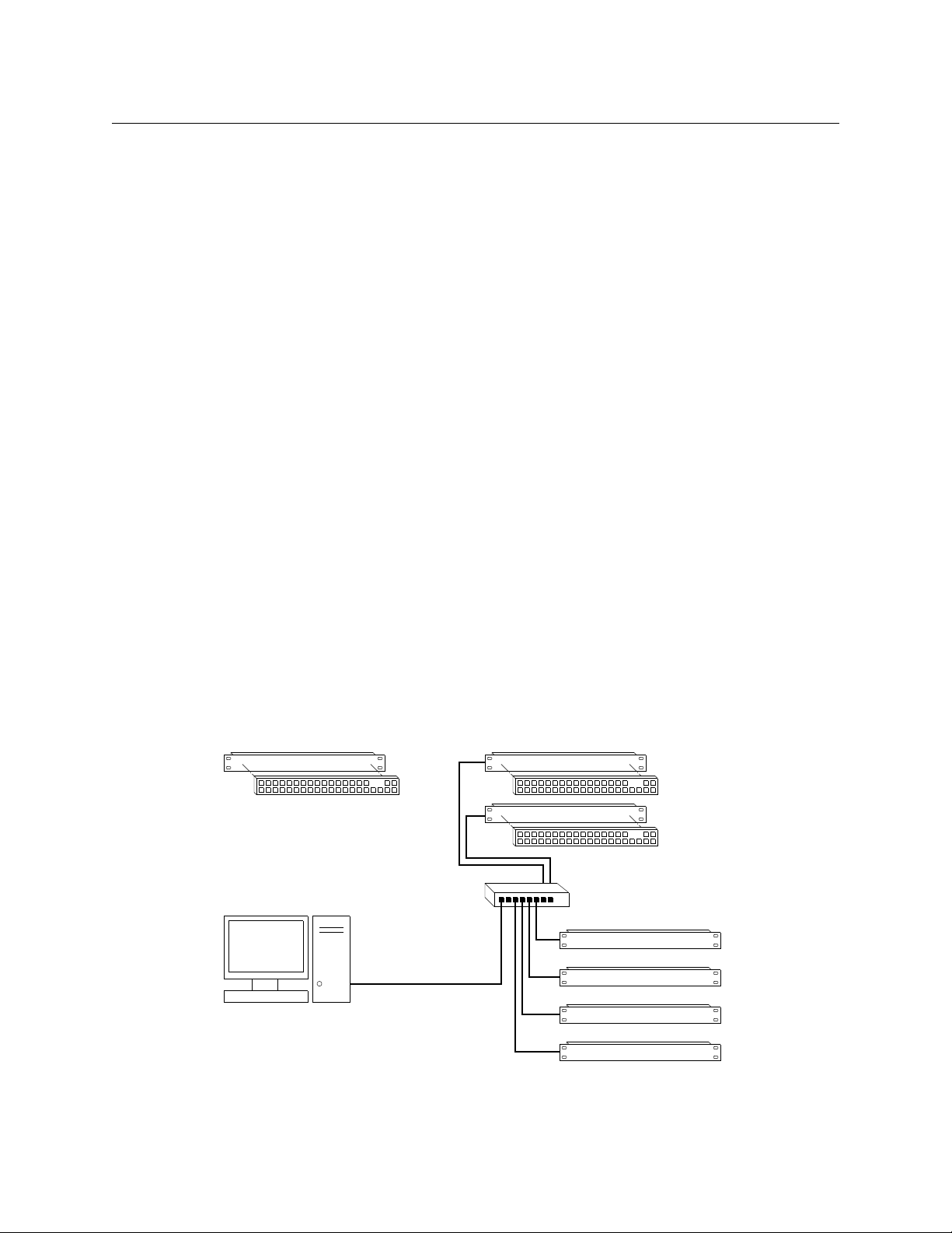
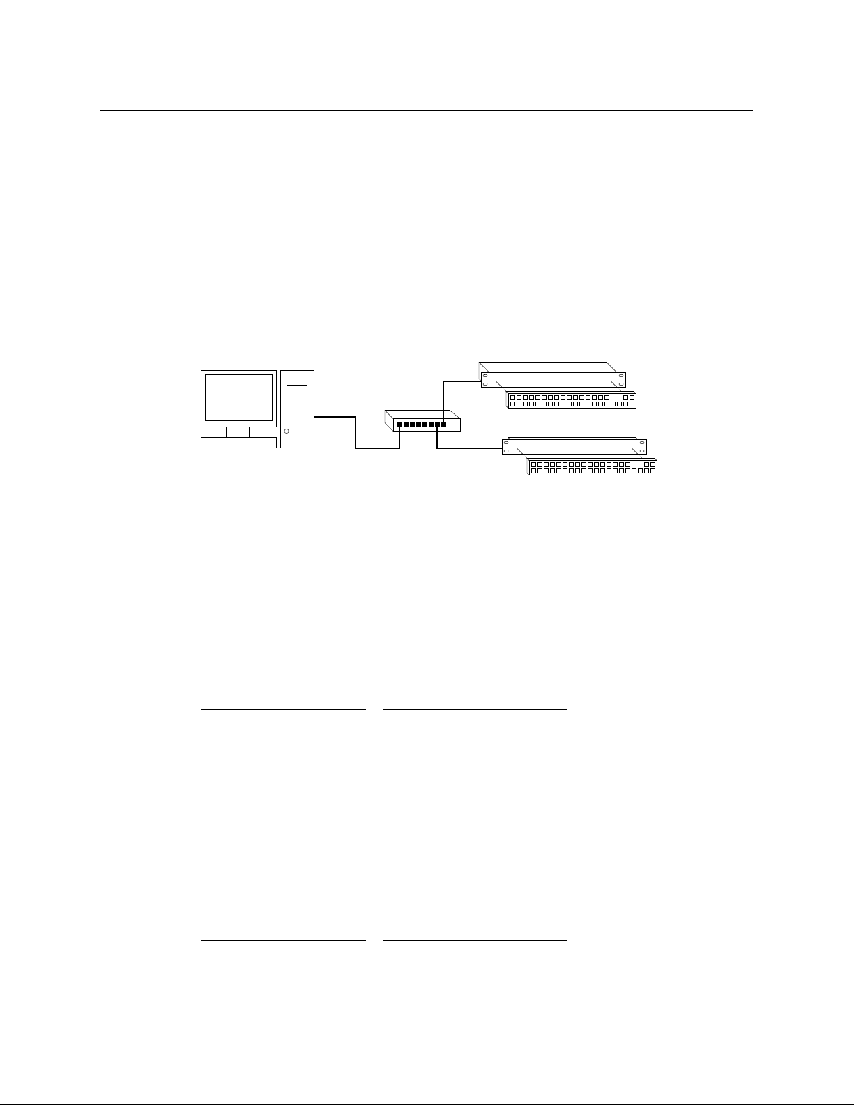
CRSC
Standalone Router and
“Captive” Control Panel
Networked Routers
with Remote Panels
Remote Panel 1
Router 1
Router 2
Router 3
Router 4
Remote Panel 2
Ethernet Switch
PC
User’s Guide
Usage
There are several ways to use CRSC (Compact Router System Configurator):
• A single stand-alone router with a “captive” control panel or with automation.
• A single stand-alone CR6400 router with a “captive” control panel or with automation.
• A network of stand-alone routers (other than CR6400 routers), possibly with remote panels,
possibly with captive panels, and with or without automation.
• A network of stand-alone CR6400 routers, possibly with captive panels, and with or without
automation.
• A CRSC network of routers and remote panels with or without automation. Here, the panels
and routers are configured using CRSC.
• A network of routers under an NV9000 family router control system.
• A single stand-alone CQX router with a “captive” CQX control panel or with automation.
• A CQX router with a remote CQX control panel.
CR6400 stand-alone routers and networks are distinguished from other types of stand-alone
routers and networks because the user interfaces are different.
Automation is possible and is left to the customer. We do not discuss it in any detail. Please
contact Grass Valley customer support if you need assistance with automation.
Routers and remote panel modules come from the factory ready for stand-alone operation. In
stand-alone mode, they work simply and reliably. However, if you want to exploit their more
elegant features, they must be configured for use either in a CRSC network or in an NV9000
network. Once configured, they will not function in stand-alone mode unless they are reset to
their factory defaults.
A remote panel module must be configured to work either in a CRSC network or in an NV9000
network. (These two configuration modes are mutually exclusive.)
Figure 1-1 compares a stand-alone router with a captive panel to a router network with remote
panel modules:
Fig. 1-1: Standalone Router vs. a Network of Routers
3
Page 16
Introduction
Remote Panel 1
Router 1
Router 2
Router n
Remote Panel 2
Config
PC
NV9000
Panel and
Router Net 2
Panel and
Router Net 1
House Net
• • •
• • •
Ethernet
Ethernet
Config
PC
Ethernet
CQX Router
Local CQX Panel
Remote CQX Panel
Hardware Summary
A CRSC network has the same topology as a stand-alone network (shown in Figure 1-1), except
(1) the routers and remote panel modules have been configured under CRSC which provides a
more elegant solution to system design than does a stand-alone network.
NV9000 Networks
Figure 1-2 shows a sample NV9000 network, one of several possible topologies:
4
Fig. 1-2: NV9000 Network of Routers
An NV9000 network supports a larger number of routers. Commands issue from the remote
panels to the NV9000 which then dispatches the instructions to the routers. The routers return
status to the NV9000 which in turn relays the status to the remote panels.
CR Series routers can be used with a NV9000 family router control system. These router control
systems extend the capabilities of the compact routers.
An NV9000 network is constructed and operated according to the requirements of the NV9000
router control system. Configuration and control of the routers is entirely within the scope of
NV9000-SE Utilities, although you can use CRSC to designate IP addresses.
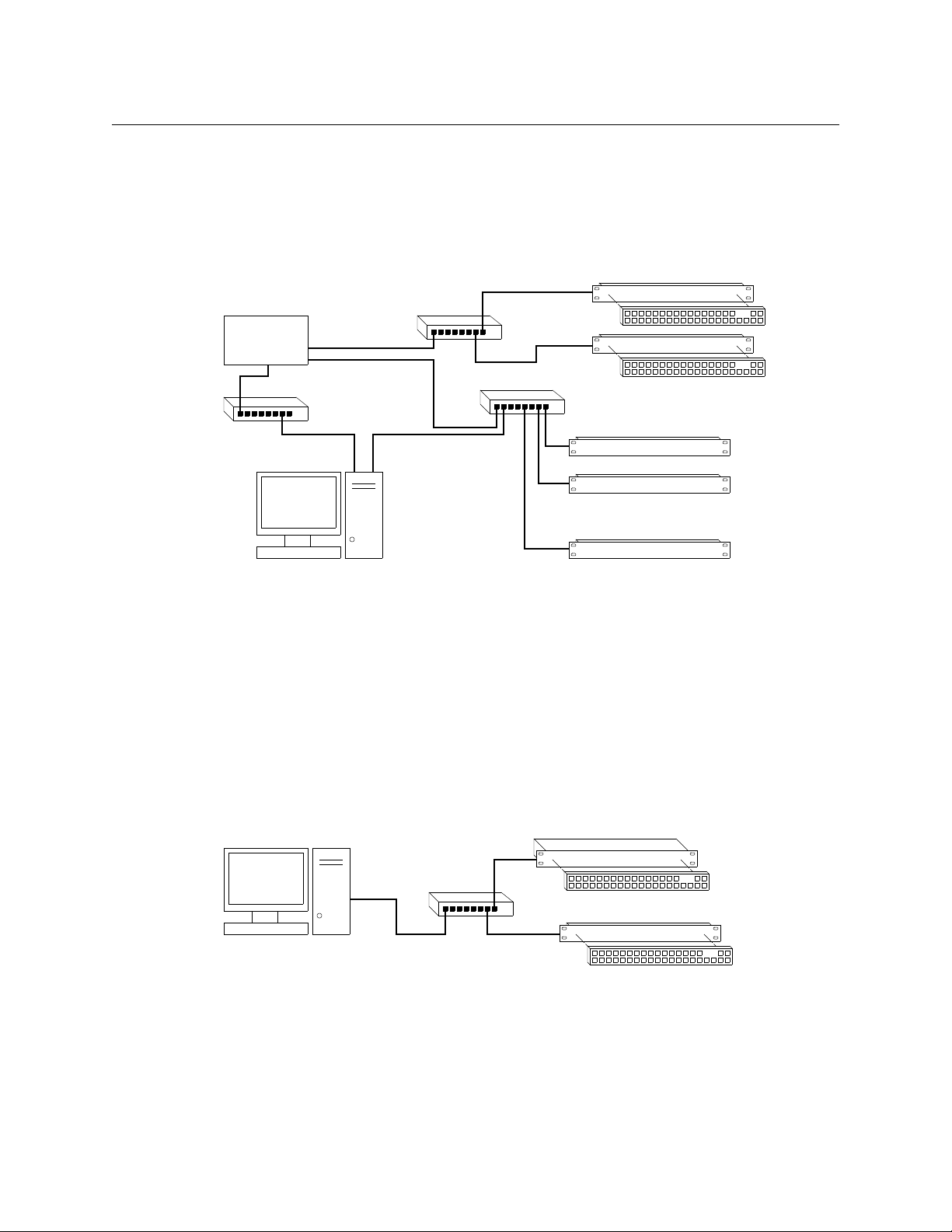
CQX Networks
Figure 1-3 shows the ways a “clean and quiet” router can be connected:
Fig. 1-3: CQX Network
At present, the CQX connections are limited. One CQX router with a local (or captive) CQX panel
or a remote CQX panel (or both) can exist on any subnet. (You can have more than one subnet,
however.)
At present there is little to configure other than the IP address of the router (and possibly the
remote panel module).
Page 17

CRSC Summary
CRSC (the Compact Router System Configurator) is configuration software that runs on your PC.
If you have very old compact routers and remote panel modules, they should be updated
with new firmware that is compatible with CRSC.
CRSC Features
Compared to using a stand-alone system, CRSC offers the following benefits:
• Configurable panels
A stand-alone system is not configurable.
In a CRSC system, you can create and configure router levels, and exercise control over network device addresses. You can also save and restore panel configuration files.
CRSC supports 3 panel operating modes.
• Partitioning
A stand-alone system does not allow router partitioning.
A CRSC network allows partitioning. A “level” is equivalent to a partition.
• Configurable networks
A stand-alone network comprises up to 4 routers and up to 16 remote panels. IP addresses
depend on the devices’ rotary switches and router levels are limited to the range 1–4.
A CRSC network supports up to 4 routers, up to 8 levels, and up to 16 remote panels. IP
addresses are configurable.
You can create many CRSC networks. If you do, CRSC can manage them all at once as long as
your configuration PC has the network connections to do so. CRSC accesses multiple CRSC
networks on different subnets.
• Efficient multi-level ‘takes’ and breakaway
In a stand-alone system, panel buttons have a fixed, predefined, and limited association with
router inputs and outputs.
In a CRSC network, remote panel buttons have a configurable association with router inputs
and outputs. In fact, remote panels control sources and destinations, not merely inputs and
outputs. Consequently, CRSC systems can use available equipment more effectively.
Remote panels configured in “enhanced” mode provide automatic level selection. Remote
panels in a CRSC system provide a form of breakaway status. (See Remote Panel Modes
page 47.)
• CRSC systems can perform salvos. (Salvos are stored take sequences.)
• CRSC itself can perform system monitoring. You can examine and set crosspoints and view
and clear locks from your PC.
• CRSC simplifies firmware updates with a single file for all CR Series devices. All of your CR
Series devices can (and should) be updated at the same time.
You can also use CRSC to initialize your remote panel module(s) for use with a NV9000 network
and to restore those remote panel module(s) to use under CRSC.
Using CRSC, configuration changes can be made easily and quickly.
CRSC
User’s Guide
on
5
Page 18
Introduction
CRSC Summary
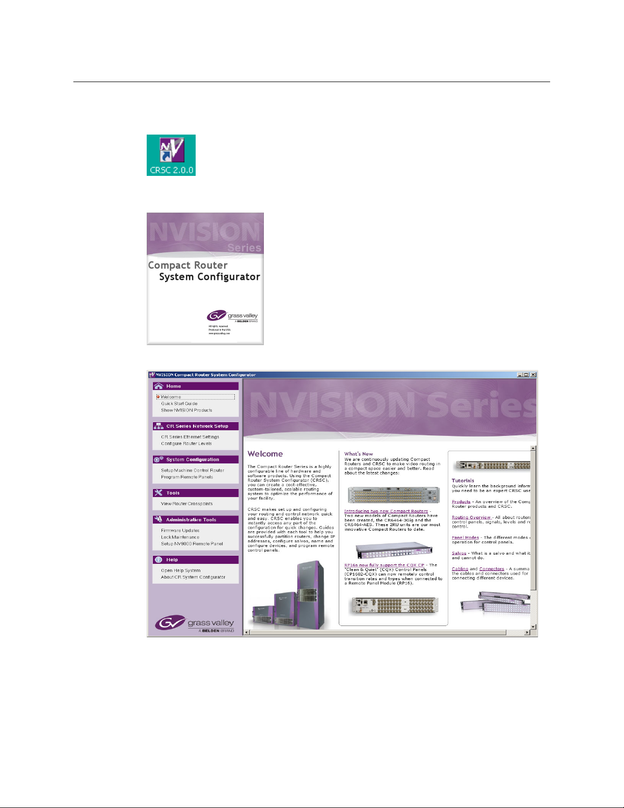
CRSC User Interface
After CRSC is installed, you will probably have its icon on your PC desktop:
Double-click the icon to launch CRSC. When you launch CRSC, you will momentarily see its
“splash” screen:
Then the CRSC window appears with its “welcome” page displayed:
6
Page 19
CRSC
Navigation Pane Work Area
Red
dot
User’s Guide
The CRSC window is divided into two main parts, a navigation pane at the left, and a work area
at the right:
By clicking the different entries in the navigation pane, you can select different pages in the
work area. When you click a navigation entry, a red dot appears to the left of that entry. The red
dot serves as a visual aid to remind you which page you are viewing.
Following is a summary of the different pages:
• Welcome
The welcome page gives you a brief introduction to CRSC and provides links to tutorial
material.
• Quick Start Guide
The quickstart guide gives you a short lesson on using CRSC
— enough to get you started.
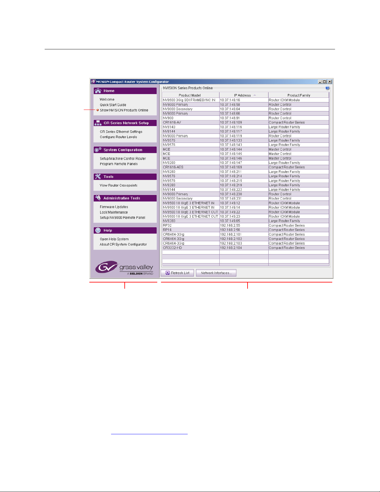
• NVISION Series Products Online
The ‘NVISION Series Products Online’ page lists all the NVISION series products detectable on
the networks to which your configuration PC is connected. These include large routers,
NV9000 control systems, and master control products, as well as compact routers and
remote panel modules.
(See NVISION Series Products Page
on page 23.)
7
Page 20

Introduction
CRSC Summary
• CR Series Ethernet Settings
The ‘CR Series Ethernet Settings’ page lists all the CR Series products detectable on the networks to which your configuration PC is connected. These include only compact routers and
remote panel modules.
It is in this page that you assign the devices IP addresses on a CRSC network.
(See Ethernet Settings Page
on page 25.)
• Configure Router Levels
Use this page to define the levels associated with the routers. A router corresponds to at
least one level. A level is the same thing as router partition and essentially defines the size
and type of a switching matrix.
Assigning a level to a router (and clicking the page’s ‘Apply Updates’ button) places the
router in what CRSC calls “config” mode and the router will no longer function in standalone mode. If you accidentally do this, you can easily restore the router to its factory
default state. See the Compact Router User’s Guide for instructions.
(See Router Levels Page
on page 29.)
• Set Up Machine Control Router
Use this page to designate the port types for machine control routers.
(See Machine Control Routers Page
on page 37.)
• Program Remote Panels
Use this page to configure the buttons of remote panels.
(A remote panel is a CR Series control panel mounted on a remote panel module.)
(See Remote Panels Page
on page 43.)
• View Router Crosspoints
Use this page to view the native crosspoint matrices of various compact routers and to perform primitive takes in those routers.
(See Router Crosspoints Page
on page 71.)
• Firmware Updates
It is in this page that you can update the firmware of selected compact router and remote
panel modules.
(See Firmware Updates Page
on page 91.)
• Lock Maintenance
Use this page to examine and clear locks and protects made by various users. You cannot set
locks in this page.
(See Locks Page
on page 99.)
• Set Up NV9000 Remote Panel
Use this page to change a panel from one that operates in CRSC mode to one that operates
in NV9000 mode or vice versa. Those two modes are mutually exclusive.
(See NV9000 Remote Panel Settings Page
on page 103.)
8
Page 21

CRSC
User’s Guide
• Open Help System
This entry in the navigation pane does not select a page in the work area, but launches
CRSC’s interactive help system. (The interactive help is an on-line version of this document.)
• About CRSC
This page provides the CRSC version number and Grass Valley contact information.
Creating a CRSC Network
CR Series products (and CRSC) communicate on an Ethernet LAN. There are three main reasons
to create a network:
• To perform multi-level operations, such as ‘takes’ and locks.
• To operate routers or a network of routers remotely (e.g., from a separate room).
• To make use of CRSC features, such as configurable remote panels. (But remember that it is
actually the remote panel module that is configurable.)
CRSC can access multiple subnets. Each subnet can include the following items:
• From 1 to 16 remote panel modules (with attached control panels).
• From 1 to 4 compact routers. You can mix CR Series routers of any size and type according to
your requirements.
If you are also using any CQX routers and control panels, a second, separate subnet must be
created for the CQX products.
The control panels and routers communicate by sending messages across the network. If any
routers or control panels on the network have duplicate IP addresses, the devices are not distinguishable and the network will not functions properly. CRSC will notify you of any duplicate IP
addresses and tell you which frames are inaccessible on a specific subnet.
You can create multiple CRSC subnets. CRSC can detect and manage all subnets as long as your
configuration PC can connect to the different subnets.
IP Addresses
An IP address is a 32-bit number usually expressed by four 8-bit values (octets) in decimal notation separated by periods: 192.168.2.87 (for example). The 32-bit number has two parts: a
subnet identifier and a device address with the subnet.
For example, if a router’s full IP address is 192.168.2.87, and the subnet mask is 24 bits, the
router’s address is 87 and the subnet is 192.168.2.xxx.
Subnets
A subnet allows a single large network to be organized into smaller sub-networks. Typically, a
subnet may represent all the machines at one geographic location or on the same local area
network (LAN).
A CQX router and control panel must be on its own subnet.
A router can receive commands only from a control panel on the same subnet.
9
Page 22

Introduction
CRSC Summary
Subnet Masks
A subnet mask a set of bits that Ethernet uses to divide an IP address into a subnet field and a
field for a device address that exists in that subnet. For compact routers, the typical subnet mask
is 24 bits (out of 32):
11111111 11111111 11111111 00000000
and this is typically represented by 255.255.255.0. For such a subnet, there are 256 possible
device addresses. The addresses 0 and 255 are reserved. Device addresses can therefore range
from 1 to 254.
The subnet masks need not be 24 bits. If it differs, the device address range will be something
other than 1–254.
Rotary Switches
The 16-position ‘Frame ID’ rotary switches (located at the front of a router or remote panel
module) are used in the following circumstances:
• When a router is stand-alone or in a stand-alone network.
• In a CRSC network, when the router or remote panel module is still in its default state (e.g.,
when you are in the process of adding a router or remote panel module to the CRSC network).
Otherwise, in a CRSC network, the rotary switch settings have no importance.
Adding Devices to a CRSC Network
When you are adding a router or remote panel module to a CRSC network, the 16-position
rotary switch determines its initial IP address. Routers and remote panel modules usually come
from the factory with the rotary switch set to position 1.
The 16 positions are numbered (in hex) from 0 to F. In hex notation, letters represent digits
greater than 9:
A = 10, B = 11, C = 12, D = 13, E = 14, F = 15
The value of the switch is then added to a fixed number to create the initial IP address for the
router or remote panel module. Letting the subnet be represented by xxx.yyy.zzz,
For CQX routers, the IP address = xxx.yyy.zzz.sss where sss = switch value + 200. Use only a
switch setting in the range 1–4 (resulting in an address range of 201 to 204).
For other compact router routers, the IP address = xxx.yyy.zzz.sss where sss = switch value +
100 (resulting in an address range of 101 to 104).
For remote panel modules, IP address = xxx.yyy.zzz.sss where sss = switch value + 50. Use
only a switch setting in the range 1–15 (resulting in an address range of 51 to 65).
Note carefully that if a rotary switch is set to zero, the router or panel reverts to the factory
default state (when it powers up) and not to a previously set state. Do not use a switch setting of
0 when you are adding a router or remote panel module to a CRSC network!
A router and a remote panel module can have the same switch setting because each is being
added to a different base number. However, two routers or two control panels cannot have the
same switch setting because the resulting number would be the same, creating identical IP
addresses.
10
Page 23
CRSC
Config
PC
Ethernet
CQX Router
Local CQX Panel
Remote CQX Panel
User’s Guide
After the devices are added to your network, you can use CRSC to assign them specific IP
addresses. (The new addresses must be written to the devices from CRSC.) After that, the
devices are no longer in their default state, but belong to the CRSC network and the rotary
switches are irrelevant (except that they must not be set to 0).
Remember that each device must have a unique IP address.
CQX Networks
A CQX router must be operated with a CQX control panel (or automation). Do not place a CQX
router on a subnet with other routers. However, you can have more than one subnet dedicated
to supporting CQX routers.
Figure 3-3 shows the ways a “clean and quiet” router can be connected:
Fig. 1-4: Figure 3-3. CQX Network
The CQX panel can be local (mounted on a CQX router) or it can be remote (mounted on a
remote panel module). The remote CQX panel then must be connected to the CQX router by an
Ethernet switch. It is possible to use both a captive panel and a remote panel.
Unlike other compact routers, the CQX routers have two rotary switches. You must set both
switches to an appropriate value.
Mode Rotary Switch for CQX Routers
The 16-position ‘Mode’ rotary switch configures the router’s video format. Set the rotary switch
to a position in the range 0–9, A, B, C, or D, according to this table:
Setting Format Setting Format
0 1080i, 59.94 or 60
1080p, 29.97 or 30
1080psf, 29.97 or 30
1 1080i, 50
1080p, 25
1080psf, 25
2 525i, 59.94 C 720p, 23.98 or 24
3 625i, 50 D 1080p, 23.98 or 24,
4 720p, 59.94 or 60
5 720p, 50 E reserved
6 1080p, 59.94 or 60
7 1080p, 50
8 2 × 1080i, 59.94 or 60
9 2 × 1080i, 50
A 720p, 29.97 or 30
B 720p, 25
1080psf, 23.98 or 24
F reserved
Switch positions 6 and 7
correspond to video according to SMPTE 425 level A.
Switch positions 8 and 9
correspond to video according to SMPTE 425 level B.
The default is 1080i, 59.94 Hz (switch setting 0). Positions E and F are not valid positions.
11
Page 24

Introduction
Usage Tips
Usage Tips
Where a switch setting supports multiple formats, the format is governed by the video reference
applied to the router and must be compatible with that reference format.
When a control panel is mounted on a router or remote panel module, it conceals the rotary
switch. You must remove the control panel when you are setting the rotary switch.
Every time you make a switch change, power-cycle the router or remote panel module.
Network Speed
Compact router networks are Ethernet LANs (100 Mb/s, UDP). That means they are reasonably
fast, and have potentially many network configuration options. However, no matter how fast the
network is, the amount of network traffic increases exponentially with the number of devices on
the network. At some point, the traffic exceeds the capacity of the network. The practical limit is
4 compact routers and about 16 remote panel modules.
Network Considerations
Compact routers (and remote panel modules) were designed to use 10/100BaseT networks,
occasionally auto-negotiating to 10BaseT.
Modern 100/1000BaseT switches (such as those offered by Cisco) will stop sending router traffic
when a compact router goes to 10BaseT.
Such auto-negotiating tends to occur where CAT 5 cable lengths exceed 25 meters.
Our recommendation for network equipment is this: use a 10/100BaseT unmanaged switch for
your compact router network. These switches should reliably support CAT 5 to 100 meters or
better.
The CR6400 routers are immune to this problem, having parts of more recent design.
12
Cabling
Compact routers generally use 75W BNC cable for signal connections. However, machine control
connectors are RJ-45 and analog audio connectors are DB25. Each DB25 connector supports 8
audio channels (4 stereo pairs). You will need to acquire breakout cables to connect individual
analog audio devices, such as Grass Valley’s WC0053 breakout cable.
CR6400 routers use DIN 1.0/2.3 connectors for signal connections. We call these connectors
“coax” connectors.
The CR Series devices use RJ-45 connectors for Ethernet.
Power-Up Re-initialization
A router or remote panel module re-initializes to its factory default settings if you power it up
with the rotary switch set to zero (0). If you reset the frame by accident, and the frame is in your
network, you will have to add the frame again and reconfigure it.
Page 25

CRSC
User’s Guide
Uploading Firmware
You will receive a firmware file when your receive CRSC. You can receive firmware updates periodically or upon request.
We recommend that when you receive a firmware file, you upload the firmware to all your
compact routers and remote panel modules before proceeding. See How to Update Firmware
on page 95.
Panels Locked at Reset
After a reset, a panel is locked. Before you can use a panel, you must unlock the panel by
pressing the red ‘Panel Lock’ button.
System Design
By the time you are ready to use CRSC, most of the compact router system design decisions
have likely already been made. However, it may be helpful to review the following points to
ensure that all issues have been captured in your system design.
Design Issues
What signals does you system manage? How many signals are there?
What are the signal types? Do you need or have machine control routers?
Are you using CQX (“clean and quiet”) routers? If so, CQX routers only operate by themselves
with CQX control panels and must be on a separate subnet from other routers.
The CR6400 routers have an architecture that differs slightly from the architecture of the other
CR Series routers. Be aware of those differences. Please refer to the CR6400 Family User’s Guide.
A compact router has a maximum of 16, 32, or 64 inputs or outputs. (An AES router in mono
mode has a 64×64 matrix although it is still considered a 32×32 router.) How you partition a
router depends in part on the organization of buttons on your control panels and similarly the
organization of buttons depends in part on router partitions.
Router partitions are contiguous sets of connectors in the ordering of connectors on the router.
A partition cannot consist of a disjoint set of connectors.
Router partitions may overlap if it suits your system design.
Router partitions, especially for AES or machine control routers, depend on many factors:
AES partitions
Machine control partitions
HD routers can switch SD signals. You do not need a separate SD router. If you have a 3Gig
router, it can switch HD and SD signals as well as 3Gig signals.
You can switch analog signals using analog video (AV) and analog audio (AA) routers. You can
also use analog-to-digital (A/D) and digital-to-analog (D/A) converters in conjunction with HD,
SD, and AES routers when you have analog signals. Whether this is an effective solution depends
on factors that include your budget, whether you need or already have A/D and D/A converters,
and how much delay you can tolerate in your video or audio.
Whether your video signals contain embedded audio is another issue. Do you actually need any
audio routers?
— number of AES channels. Number of embedded audio channels.
— what kind of devices you have that require machine control.
13
Page 26
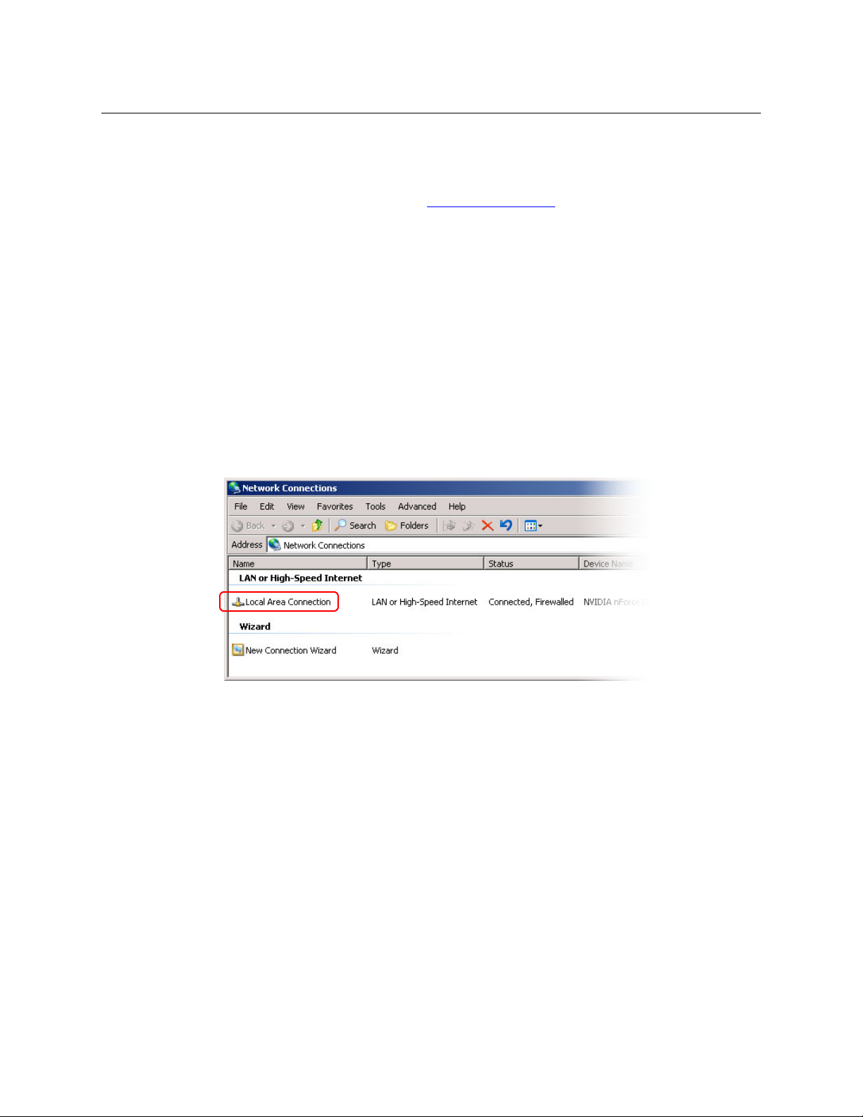
Introduction
Setting Up Your Configuration PC
CR Series routers and panels do not start, stop, rewind, cue, or otherwise control any media. You
might need to purchase equipment that performs those tasks. You must consider how that
equipment works in conjunction with CR Series products.
For additional information, review the Sample Configuration
issues that you might encounter.
Setting Up Your Configuration PC
Your configuration PC must be assigned an IP address on one or more of the subnets you intend
to use for the CRSC network.
If you have multiple subnets in your compact router system, you will probably have to add those
subnets to your PC’s network configuration. Doing this is especially important for CQX routers.
How to Configure your PC’s IP Address(es)
1 From the PC’s Start menu, choose ‘Settings > Network Connections’ or 'All Programs >
Accessories > Communications > Network Connections', whichever is available. The ‘Network Connections’ dialog box appears:
on page 116. It illustrates design
14
Fig. 1-5: Network Connections Window
Page 27
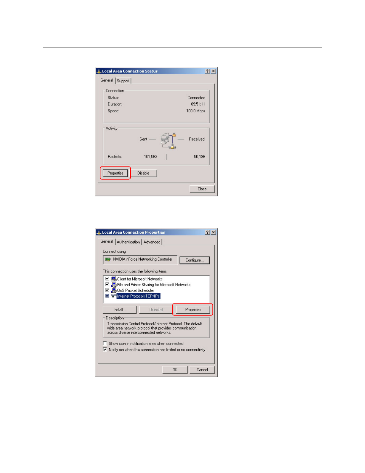
CRSC
User’s Guide
2 Double-click ‘Local Area Connection’. The ‘Local Area Connection Status’ dialog box appears:
Fig. 1-6: Local Area Connection Status Dialog Box
3 Choose the ‘General’ tab and click Properties. The ‘Local Area Connection Properties’ dialog
box appears.
Fig. 1-7: Local Area Connection Properties Dialog Box
15
Page 28
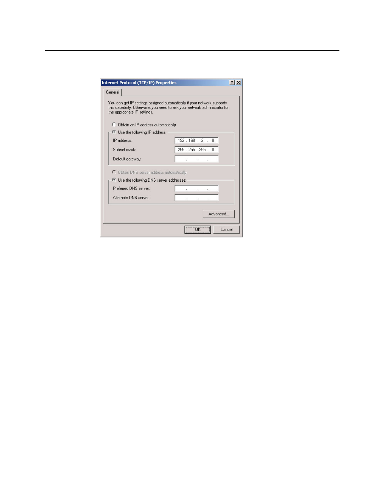
Introduction
Installing CRSC
4 Select ‘Internet Protocol (TCP/IP)’ and click Properties. The ‘Internet Protocol (TCP/IP) Prop-
erties’ dialog box appears.
Fig. 1-8: Internet Protocol (TCP/IP) Properties Dialog Box
5 Select ‘Use the following IP address’ and enter the IP address for your PC. It is recommended
that you use the default subnet 192.168.2.xxx and the subnet mask 255.255.255.0.
Any unique IP address will work as long as it is on one of the subnets of your CRSC network.
The PC’s address on the subnet must not be the same as any of the frames (routers or remote
panels) on the subnet. It is recommended that you use Avoid addresses in the 50, 100 and
200 range. CRSC uses those as defaults. For details, see IP Addresses
6Click OK to save your changes.
How to Create Multiple Subnets
1 Starting from step 4 in the preceding procedure, click Advanced.
2 In the ‘Advanced’ window, click Add and enter an IP address for your PC on each of the sub-
nets. Repeat this step for additional subnets.
3 After adding IP addresses for your subnets, click OK.
Installing CRSC
CRSC is available on the software and documentation CD (SB0033-xx) that ships with the equipment. CRSC is a Java application and the installer installs a Java runtime support package.
You can also obtain the installer from Grass Valley customer service.
The installer creates a desktop shortcut for CRSC and makes an entry in Windows’ Start menu for
CRSC. The software installation process takes about one minute.
on page 9.
16
Page 29
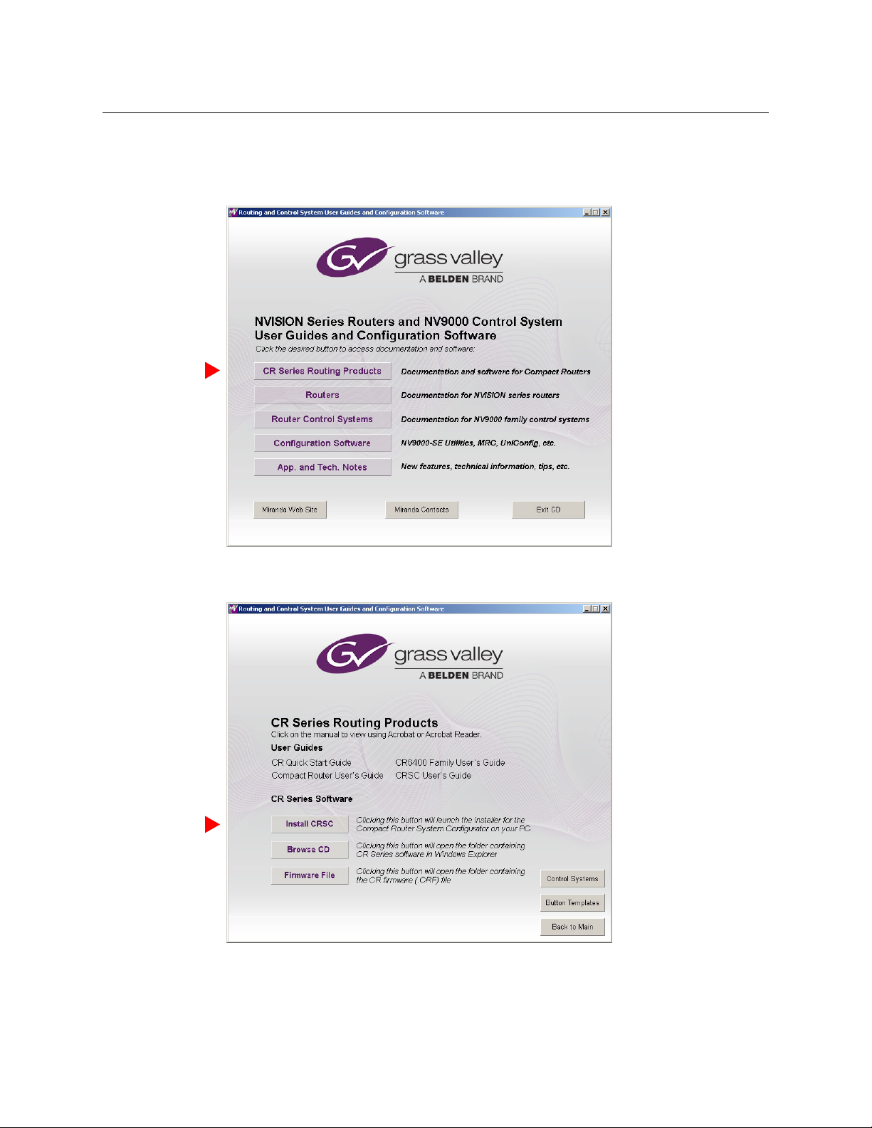
Follow these steps to install CRSC:
1 Insert the CD in your CD drive.
Wait for the initial screen:
CRSC
User’s Guide
Click the ‘CR Series Routing Products’ button.
2 The ‘CR Series Routing Products’ page appears:
Click ‘Install CRSC’.
17
Page 30
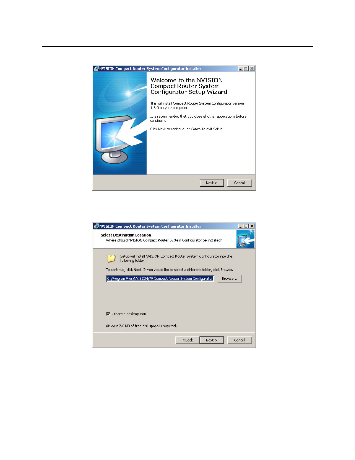
Introduction
Installing CRSC
3 The installation script will begin to run:
Click ‘Next’.
4 A window appears in which you can designate the location on your PC in which to install
MRC:
18
The window presents the default location. If you prefer another location, click ‘Browse’ to
navigate to a different folder.
Uncheck ‘Create a desktop icon’ if you do not want a CRSC shortcut to appear on your PC
desktop.
The window tells you the disk space needed for the installation. If you do not have that
much space, the installation will fail.
When you are satisfied with the pathname and options, click ‘Next’.
Page 31

5 A confirmation window appears:
CRSC
User’s Guide
If the options presented are not correct, click ‘Back’ to go back to the previous window and
re-enter a pathname or change options.
Otherwise, click ‘Next’ to start the installation or click ‘Cancel’ to stop the installer.
When you start the installation, a progress window appears:
19
Page 32

Introduction
Installing CRSC
6 After several seconds, the installation will complete. The completion window appears:
Uncheck ‘Launch Compact Router System Configurator’ if you do not want to run CRSC
immediately.
7 Click ‘Finish’.
Installation Testing
After installing CRSC, launch CRSC by clicking its desktop icon or selecting ‘NVISION > Compact
Router System Configurator’ from the Windows ‘Start’ menu. Go to the ‘CR Series Ethernet
Settings’ page. Click ‘Refresh List’.
Examine the list of devices and note whether any of the following conditions exist:
• No entries in the list.
You have no network (or no devices on your network) or the network is not properly connected to your PC. Ensure that your PC has an Ethernet connection to the Ethernet switch for
the network.
Click the ‘Network Interfaces’ button in CRSC’s ‘NVISION Series Products Online’ page to determine to which subnets your configuration PC is connected.
• Entries read “IP Conflict.” To correct this, find and change IP address so that all IP addresses
are distinct.
• If you determine that IP addresses are not a problem, one or more of the frames might be
disconnected, have no power, or might be defective. Again, check Ethernet connections,
power connections, and power supplies. A power supply light and the power indicators on
all routers, remote panel modules, and control panels should be on.
20
Page 33

• Entries read “Different Subnet.” These are frames that are detectable by CRSC, but are not on
a currently available subnet. To view available subnets, hover your mouse over the text “Different Subnet.” A popup list of available subnets appears.
There are several options for such entries:
Change the IP address of the frame to the current subnet.
Change the IP address or subnet of the configuration PC.
Change the IP address in some other way, but leaving the device on some other subnet.
Physically remove the frame from the network by disconnecting the connecting cables.
Fix any problems and click Refresh List on the ‘CR Series Ethernet Settings’ page to view an
updated list of devices. When the network is functioning properly, you are ready to use CRSC to
perform other tasks.
Getting Started
Before you can use all the features of CRSC effectively, you should complete the following tasks:
1 Optionally, upload new compact router firmware using CRSC. See Uploading Firmware
page 13.
2 Be sure that any control panels are unlocked. See Panels Locked at Reset
3 Using CRSC assumes that your compact router network is designed and connected. See Sys-
tem Design on page 13 and Creating a CRSC Network on page 9.
4 Set up your configuration PC and install CRSC. See Setting Up Your Configuration PC
page 14.
5 Test the CRSC installation to verify that everything is working properly. See Installation Test-
ing on page 20.
If you are unfamiliar with routing, networking concepts, or CR series products, we recommend
that you read the Tutorials
Please refer to the CR Series User’s Guide and the CR6400 Family User’s Guide for details about the
many compact routers and (compact) control panels.
CRSC
User’s Guide
on
on page 13.
on
on page 107.
21
Page 34

Introduction
Getting Started
22
Page 35

NVISION Series Products Page
The ‘NVISION Series Products’ page lists all NVISION series products — compact routers, remote
panels, large routers, router control systems
uration PC is connected.
Click ‘Show NVISION Products’ in the navigation pane to open the ‘NVISION Series Products’
page:
Fig. 2-1: NVISION Series Products Page
— detectable on the networks to which the config-
The page shows, for each product, the product name and model, its IP address, and the device
family. Use this page for reference when determining which products can be configured. The
page is for information only.
Click Network Interfaces to get a report about the NIC or NICs (network interface cards) in your
configuration PC:
You can, at any time, click Refresh List to view the most recent state of detectable products.
23
Page 36

NVISION Series Products Page
24
Page 37

Summary
Ethernet Settings Page
The ‘CR Series Ethernet settings’ page lists compact routers and remote panel modules available
on the CRSC network. Click ‘CR Series Ethernet Settings’ in the navigation pane to view the ‘CR
Series Ethernet Settings’ page:
Fig. 3-1: CR Series Ethernet Settings Page
The table columns presents the following option or information:
Column Description
Update Check the check box to select the device listed on that row for updating.
Name Name assigned to the compact router or remote panel.
Frame type Type (or model number) of compact router or remote panel.
IP address IP address currently assigned to the device.
Subnet mask Subnet mask currently assigned to the device. It is recommended that you leave the
subnet mask at 255.255.255.0.
Gateway IP Gateways are not used except by third-party systems or occasionally by an NV9000
system. Developers may use the gateway and subnet mask fields in any way they find
useful. A gateway setting is not needed for a normal compact router setup.
Mode The ‘Mode’ column is status-only and displays how the particular router or remote
panel module is configured. These are the 3 possible “modes”:
NA — The device is either a remote panel module or a router with old software.
— The device is a router configured by CRSC.
Config
— No settings have been changed and the device is a router in the factory
Default
default mode.
Default+IP
except the IP address, and the device is a router in the factory default mode.
— For CR6400 routers only, this means that no settings have been changed
25
Page 38

Ethernet Settings Page
Summary
Column Description
Identify CP When you click ‘Identify CP’, the control panel listed mounted on the device listed on
Buttons
There are 4 buttons at the bottom of the page.
Click Refresh List at any time to cause the page to display the current state of the devices on the
network.
The Apply Updates button remains dimmed until you have made a change to a setting in the
page. When you have made changes, the software automatically checks the check box in the
rows you have change and the Apply Updates button becomes enabled. Click Apply Updates
to cause those changes to be applied.
You can also check or uncheck the check boxes manually.
Use the Add CR Series Device... button to add a device is not discovered through normal
methods, for instance, when the router is detectable on through a network gateway. Such
devices might be those on a different network. When you click the button, a dialog appears in
which you may specify the IP address of the device:
that row identifies itself, physically, by displaying a moving pattern of button lights.
This feature is helpful if you forget which panel of possibly many panels is represented
by the particular IP address. The moving button lights continue indefinitely. To turn
off the pattern, either press any button on the panel or click ‘Identify CP’ again.
26
Click OK to add the device or ‘Cancel’ if you do not want to add the device. Devices added this
way are said to be “manually” added.
Use the Remove CR Series Device... button to remove a manually added device (one that has
been added with the ‘Add CR Series Device...’ command.
First place a check mark in the table row of the device you want to remove. Then click the
button. A confirmation dialog appears:
Click OK to remove the device or ‘Cancel’ if you do not want to remove the device.
Page 39

Usage
CRSC
User’s Guide
The ‘CR Series Ethernet Settings’ page lets you can change the name, IP address, subnet mask, or
gateway IP address of any compact router or remote panel module.
Use the page to add routers and remote panel modules to your CRSC network. The process of
adding these devices involves making physical Ethernet connections and then, in CRSC,
changing the devices’ IP addresses and other data from their defaults to what you want.
(If you have previously configured a router or remote panel module, and you are adding it to
your CRSC network, it might already be configured the way you want.)
Note:
A CQX router must be operated using a CQX control panel, either mounted on the CQX router
itself or on a remote panel module.
It is important to assign each CQX router and CQX panel a subnet separate from other compact
routers or control panels. You can, of course, have more than one subnet.
How to Add Routers to a Network
Note: the limitation of 4 routers on a subnet is a physical limit imposed by the amount of
network traffic that the routers can handle. CRSC, however, will allow you to have any number of
routers on a subnet. Although you can exploit this capability for ease of configuration, you must
ensure that your compact router system observes the network limits when it is running.
Routers from the factory are usually all set to the same subnet: 192.168.2.xxx. Routers that are
freshly reset to default also use that subnet.
Adding a router to the CR system creates a new level. Routers are assigned to a subnet and no
more than 8 levels in any single subnet are allowed. CRSC will not let you delete a router you just
added because each router must correspond to at least one level. Either disconnect the router
physically, delete one or more levels (other than those just added), or move the router to
another subnet. Levels are managed using the ‘Router Levels’ page. See Router Levels Page
page 29.
Follow these steps to add routers to your network:
1 Connect up to 4 routers to your network with unique rotary switch settings in the range 1 to
F (hex).
on
Remember to cycle power after you change a rotary switch.
However, if a rotary switch is set to zero (0), and you then power-cycle the router or
remote panel module, the device reverts to the factory default state, and loses its previously configured state.
2 Go to the ‘CR Series Ethernet Settings’ page.
3 Verify that all routers appear in the list. Click ‘Refresh List’ if necessary.
4 For each router, click on the cell in the ‘IP Address’ column to edit the field. Enter a unique IP
address.
5 Repeat steps 1 through 4 for additional router. Remember that no more than 4 routers can
operate to a single subnet.
6Click Apply Updates to send the changes to the selected frames. Only those frames with
‘Update’ checked in the table rows are updated. The data are stored in the frames internally.
27
Page 40

Ethernet Settings Page
Usage
How to Add Remote Panel Modules to a Network
Follow these steps to add remote panel modules to your network:
1 Connect up to 15 remote panel modules to the network with unique rotary switch settings
in the range 1 to F.
Remember to cycle power after you change a rotary switch.
However, if a rotary switch is set to zero (0), and you then power-cycle the router or
remote panel module, the device reverts to the factory default state, and loses its previously configured state.
2 Go to the ‘CR Series Ethernet Settings’ page.
3 Verify that all added remote panel modules appear in the list.
4 For each remote panel module, click on the cell in the ‘IP Address’ column to edit the field.
Enter a unique IP address according to the following formulas:
5 Repeat steps 1 through 4 for additional remote panel modules.
6Click Apply Updates to send the changes to the selected frames. Only those frames with
‘Update’ checked in the table rows are updated. The data are stored in the frames internally.
How to Change Ethernet Settings
1 Go to the ‘CR Series Ethernet Settings’ page.
2 Locate the router or remote panel module you want to update.
3 In that row, click the cell you want to change: the IP address, subnet mask or gateway IP
address. The field opens for editing.
4 Type in the new value.
We recommend that you leave the subnet masks at 255.255.255.0.
5 To record your change, press ‹enter
your change.
6 Repeat steps 2–5 for additional changes. The ‘Update’ check box automatically displays a
check mark if you update any of the information.
7Click
Apply Updates to send the changes to the selected frames. Only those frames with
‘Update’ checked in the table rows are updated. The data are stored in the frames internally.
› or ‹tab›, or click in another field. Press ‹Esc› to cancel
28
Page 41

Summary
Router Levels Page
The ‘Router Levels’ page lets you view and change router levels:
Fig. 4-1: Configure Router Levels Page
The page is divided into two parts: above is the table of “crosspoint ranges” (or partitions) and at
the bottom is a network frame summary.
The upper table lets you view the levels defined for the subnet you select in the ‘Active Subnet’
drop-down list:
The lower table lets you review the routers on all networks detectable by your PC.
Click ‘Refresh Summary’ to be sure that you are viewing the most current information.
29
Page 42

Router Levels Page
Background Information
Background Information
You may define up to 4 levels in any single router. A level is a router partition defined by (1) its
size (or bounds) and (2) its signal type. A level is created either when you create a router partition or when you add a router to the network. When you add a router to a CRSC network, the
level that is added for that router is a default level for that router type.
You may define up to 8 levels for any single subnet.
Levels within a router may overlap or they may be distinct. A level may be the entire router or
may be limited to specific inputs and outputs.
IMPORTANT
CQX routers are designed not to use levels. For proper functioning, do not configure
levels in a CQX router.
Adding a router to a CRSC network creates a new level. Routers are assigned to a subnet and no
more than 8 levels in any single subnet is allowed.
Note: CRSC will not let you delete a level for a router you just added because each router
must correspond to at least one level. If, by adding a router, you created a level problem, you
can either disconnect the router physically, delete one or more levels (other than the one
just added), or move the router to another subnet.
Note: Grass Valley does not guarantee system performance beyond 4 routers in a subnet.
Levels and Partitions
Partitions define boundaries within the router used to organize switching. Partitions also define
what signal format is in use.
Signals are switched within a partition. It is not possible to switch an input from one partition to
the output of another partition. Every router must include at least one partition. One partition
for an entire router might be desirable.
In CRSC, partitions are called levels. CRSC allows you to define up to 8 levels for each subnet and
up to 4 levels for each router.
Modes in the Levels Table
If a router is to be used stand-alone or in a stand-alone network, do not update the levels of
family routers in this page. (If you do not change its level, the routerwill not be updated.)
If you do change the level of a router, it will enter “config” mode and be suitable only for operating in a CRSC network or an NV9000 network.
If you change only the IP address of a router, it will enter “default + IP” mode and remain suitable
for stand-alone operation.
“Config mode” is meant only for CRSC networks or NV9000 networks and not for stand-alone
routers or stand-alone networks.
30
Page 43

Using the Router Levels Page
At the top of the page, the ‘Setup Crosspoint Ranges for Levels’ table displays all levels currently
added to the selected subnet and lets you add, delete, and change levels as needed.
In the lower section of the page the ‘Network Frame Summary’ has two tabs
CR Frames’
routers. The ‘All CR Frames’ lists all CR Series devices.
The ‘Setup Crosspoint Ranges for Levels’ table display the following information for each level:
Column Description
Level Number A number assigned to the level. The number must be unique and from 1
Level Name A name you assign to the level. The name is limited to 16 characters.
Router Name The name of the router that contains the level. The router names are not
Signal Type The type of signal switched on that level. See Signal Types
Physical Input Start Use these fields to define the physical start and endpoints of the level
Physical Input End
Physical Output Start
Physical Output End
Controller Source Start I/O numbering in a remote panel might not match the physical I/O num-
Controller Destination Start
— that list the devices detectable by your PC. The ‘Routers’ tab lists only CR Series
to 250. The numbers are automatically generated.
editable.
within the router.
bers of the router. Use these fields to map the router’s numbering to the
NV9000’s numbering.
(The remote panel’s source end and destination end values are derived
from the physical start and end and the source start and destination start
values.)
If there is no remote panel in your system, you can ignore these fields.
CRSC
User’s Guide
— ‘Routers’ and ‘All
on page 32.
The ‘Network Frame Summary’ presents the following information:
Tab Column Description
Routers Name The name of the compact router.
Frame Type The type of router.
Level(s) Level numbers associated with the router. Each level is assigned a
unique number.
IP Address IP address currently assigned to the device.
Subnet Mask Subnet mask currently assigned to the device.
All CR Frames Frame Type The type of router or remote panel.
Level(s) Level numbers associated with routers.
Subnet Mask Subnet mask currently assigned to the device.
None of this information is editable.
31
Page 44

Router Levels Page
Using the Router Levels Page
Active Subnet
CRSC detects all subnets for which there are connections in your configuration PC. You can
place different frames on different subnets and use any available subnet you want. Choose the
subnet from the ‘Active Subnet’ drop-down list.:
The page refreshes its lists of levels after you choose a different subnet.
The designation “active” applies only in CRSC itself: it is the subnet you are configuring. In the
actual network, all subnets operate independently and concurrently.
Signal Types
In general, the CR Series routers can switch these signal types.
AV
AA
AES
SD
HD
3Gig
PR
The signal types for CR6400 routers are similar, but not quite the same as for other routers:
AES
3Gig
(Any single CR Series router switches exactly one signal type.)
Among routers other than CR6400 routers, AES (audio) signals and machine control signals are
handled differently from video signals. If you are unfamiliar with the various signal types, please
review Signals
Analog Video or Timecode
Analog Audio or Timecode
Synchronous AES Mono
SD Digital Video
HD or SD Digital Video
3Gig, HD, or SD Digital Video
Machine Control Reverse
Asynchronous AES
3Gig, HD, or SD Digital Video
on page 110.
How to Update a Level
1 Go to the ‘Router Levels’ page.
2 Optionally, select the subnet on which you want to change routers levels.
3 In the ‘Setup Crosspoint Ranges for Levels’ table, locate the row listing the level you want to
change.
4 Optionally, in that row, click in the ‘Level Number’ or ‘Level Name’ cell to activate the field
and enter new values. Level numbers must be unique in the range 1 to 250. Level names are
limited to 16 characters.
5 Define the physical start and end numbers for the level. These numbers identify physical
connections on the router. The numbers you enter will of course depend on what you want
to do with the router.
The default level for the router covers the entire span of inputs and outputs. For example,
the default values for a 32×32 video router are
input start = 1, input end = 32,
output start = 1, output end = 32.
32
Page 45

CRSC
User’s Guide
6 If you have a remote panel in your system, you might need to specify ‘Controller Input Start’
and ‘Controller Destination Start’ values for the level.
Click the field to enter a value in the field.
(The controller end values are derived from the controller start fields and the physical start
and end fields.)
7 When you have finished changing level data, click Update Router Levels to send the level
configuration data to the routers. You should see a confirmation message:
Note that the ‘Update Router Levels’ button updates only the levels that were changed.
Other levels remain unaffected. This is particularly important for the levels of CR6400 routers.
How to Add a Level
1 Go to the ‘Configure Router Levels’ page.
2 Optionally, select the subnet on which you want to add routers levels.
3 Click the Add Level . . . button.
If your subnet has more than one router, a dialog appears:
Choose a router from the drop-down list and click OK. (The routers you choose are those
that exist in the selected subnet.)
If your subnet has no routers, you will receive a message stating that CRSC cannot create levels where there are no routers.
If your subnet has more than 8 levels, you will receive a message stating that a subnet cannot have more than 8 levels.
4 If there were no failures in step 3, CRSC creates a new level, with a new (unique) level num-
ber for the router you chose.
If your subnet has only a single router, CRSC simply adds a level identical to the existing
level.
IF your subnet has more than one router, CRSC adds a default level for the router you chose
in the dialog of step 3.
You can now edit the parameters for this level. (See How to Update a Level
5 Repeat steps 2–4 for additional levels.
on page 32.)
33
Page 46

Router Levels Page
Using the Router Levels Page
When you have finished adding levels, click Update Router Levels to send the level configuration data to the routers. You should see a confirmation message:
Note that adding a level creates an additional level for one of the routers that already exists on
the subnet. You cannot create levels that do not correspond to a router.
This is especially useful when you are planning to use an AES router to switch multiple AES
levels, as illustrated in this example:
Here the AES router switches two levels, AES1/2 and AES3/4. Each of these levels includes 16 AES
pairs (32 mono channels). These levels can switched nearly simultaneously under a multi-level
take performed at a remote panel. Note that the controller start values for both of these levels is
1 (and the controller end values, derived and not shown, are 32.)
There is a shortcut. Right-click a row to cause the context menu to appear:
Choose ‘Add Level . . .’ The “Select a Router” dialog appears with the router identified in the row
you clicked selected. You can use that router or choose a different router. In that dialog, click OK
to choose the router or click Cancel if you change your mind.
How to Delete a Level
1 Go to the ‘Configure Router Levels’ page.
2 Optionally, select the subnet on which you want to delete routers levels.
3 Click on row in the crosspoint ranges table to select that level.
4 Click the Delete Level... button. A dialog appears:
34
Click Ye s to delete the level. Click No to cancel.
Page 47

CRSC
User’s Guide
There is a shortcut. Right-click a row to cause the context menu to appear:
Choose Delete Level . . . and respond Ye s or No to the dialog (shown above) that appears.
When you have finished deleting levels, click Update Router Levels to send the level configura-
tion data to the routers. You should see a confirmation message:
35
Page 48

Router Levels Page
Using the Router Levels Page
36
Page 49

Summary
Machine Control Routers Page
Click the ‘Setup Machine Control Router’ entry in the navigation pane to access the machine
control routers page:
The page has two regions. Above is a table in which you can configure each port of a machine
control router.
Below is a ‘Network Frame Summary’. You can select a machine control router in its ‘Machine
Control Routers’ tab by clicking the radio button in the row for that machine control router. If
your system has no machine control routers, this table will be empty.
Click ‘Refresh Summary’ at any time to be sure that you are viewing the most current
information.
37
Page 50

Machine Control Routers Page
SRC DST
RouterControlling device
Controlled device
SRC DST
RouterControlled device
Controlling device
Background Information
Background Information
CR Series machine control routers are different from other compact routers:
• Machine control routes are bidirectional. Unlike video or audio routers, information flows
both ways.
• Machine control routes are point-to-point — one input connects to one output at most.
(Some ports might be tristated in which case they connect to nothing.)
• The ports of machine control routers are RS-422 using RJ-45 connectors. Each port can be
configured as a receiver or as a transmitter, either during configuration or dynamically as
needed.
For more information about machine control signals, see Signals
Note
Some external devices must be placed in “remote” mode to work with a machine
control router.
Machine Control Port Types
Machine control routers do not have X/Y crosspoints per se, but allow point-to-point connections. One input may connect to (at most) one output.
The 1RU machine control router has 16 bidirectional serial ports (RJ-45). It supports up to 8
routes.
The 2RU machine control router has 32 bidirectional serial ports (RJ-45). It supports up to 16
routes.
Machine control routers convey serial data, typically commands in one direction and responses
in the other direction. Because the connections are bidirectional, a port is both an input and an
output.
Machine control routers are defined as “data reverse” routers. Each port can be configured as
dynamic, master, slave, controlling, or controlled.
The machine control routers support serial communication up to 1Mb/s.
on page 110.
Terms
A device can be considered a “controlled” device or a “controlling” device.
Above, the source device is a controlling device. A destination can also be the controlling
device:
38
Page 51

CRSC
User’s Guide
A controlling device sends commands to a controlled device. The controlled device passes
responses (such as status) back to the controlling device. A source device can be a controlling
device or a controlled device. A destination device can be a controlling device or a controlled
device.
Some external devices must be placed in “remote” mode to work with a port router.
A controlling port is one connected to a controlling device.
A controlled port is one connected to a controlled device.
The compact machine control routers operate in “data reverse” mode. This means that in any
connection, the destination device is the controlling device by default. The default can be overridden by port type.
The 5 port types are variations of “controlled” or “controlling”:
Controlling Master Dynamic
Controlled Slave
It is in CRSC’s machine control routers page that you can specify the individual port types for a
machine control router. See How to Change a Port Type
on page 42.
Controlling or Controlled
These port settings fix the direction of the router port to “controlling” or “controlled.” The port’s
connection for Tx and Rx
operation.
— made during configuration — is static and does not change during
Dynamic
A dynamic port in the router can be a controlling or controlled port depending on whether it is
connected to a master port or slave port in the router. The port’s configuration is dynamic and
can change during operation.
Dynamic ports are typically assigned to VTRs.
Master or Slave
Any dynamic port of the router connected to a “master” port of the router will be changed to a
controlled port. A “slave” port is the opposite of a “master” port: any dynamic port connected to
a slave port will be changed to a controlling port.
The compact router applies logic to the port direction setting when a master port is connected
to a dynamic port. In this case, the machine at the dynamic port is always controlled and the
machine at the master port is always controlling.
39
Page 52

Machine Control Routers Page
Background Information
Machine Control Router Crosspoints
The display of machine control “crosspoint matrices” is different from that of other matrices.
Fig. 5-1: Machine Control Crosspoints
See Router Crosspoints Page on page 71.
In the matrix of Figure 5-1, ports 4 and 7 are connected. The square (A) at row 4 and column 7 is
highlighted. The square (B) at row 7 and column 4 is also highlighted.
For machine control crosspoints only, when you click on a square in column C and row R, the
squares at positions (C,R) and (R,C) become highlighted.
If the two ports (in this example, ports 4 and 7) are dynamic ports, then clicking box A and
clicking box B give different results. Either way connects ports 4 and 7, but clicking box B makes
port 7 “controlled” whereas clicking box A makes port 7 “controlling.”
Clicking box A has the same effect as pressing destination (DST) 7 then source (SRC) 4 on a
control panel.
Clicking box B has the same effect as pressing DST 4 then SRC 7 on a control panel.
Reminder: A controlling port is defined as one that is connected to a controlling device. A
controlled port is one connected to a controlled device.
Reminder: A dynamic port is one that can change direction during operation. If a port is not
dynamic, it cannot change from its configured state.
Thus, in general, clicking column C, row R has the same effect as pressing DST C then SRC R:
columns are destinations and rows are sources.
Be aware that when a port appears on the diagonal of the matrix, it is tri-stated or disabled. It
neither transmits nor receives. (Clicking a column head for a machine control router is a no-op.)
40
Page 53

You can click the upper left corner of the crosspoint matrix (above and to the left of column 1,
row 1) to force a “diagonal” take for the router. This places all the ports into tristate and they all
appear on the diagonal of the displayed matrix.
Using the Machine Control Router Page
The ‘Machine Control Port Settings’ table displays all port types for the machine control router
you select in the ‘Machine Control Routers’ table at the bottom of the page.
To change the port type, click an entry in the ‘Port Type’ column and select type from the dropdown list:
CRSC
User’s Guide
Fig. 5-2: Machine Control Port Specification
The ‘Machine Control Port Settings’ section displays the following:
Column Description
Port Number Port number of a port on the machine control router. Because machine
control ports are bidirectional, these numbers represent both inputs and
outputs.
Port Type Port type assigned to the port. There are five port types. (See Machine
Control Port Types on page 38.) Port types are selected from the drop-
down list.
41
Page 54

Machine Control Routers Page
Using the Machine Control Router Page
The ‘Network Frame Summary’ presents the following option and information:
Tab Column Description
Machine Control Routers
Levels Level The level names (with level numbers).
All CR Frames
(lists all frames
in the system)
Edit Select the radio button on the row listing the router you want to
view or edit in the ‘Machine Control Port Settings’ table.
Name Name of the router.
Frame Type Type (model number) of router.
Level(s) Level numbers associated with the router.
IP Address IP address currently assigned to the device.
Subnet Mask Subnet mask currently assigned to the device.
Signal Type Type of signal(s) assigned to the level.
Router Router to which the level is assigned.
Physical Inputs The physical input and output ranges of the routers.
Physical Outputs
Controller
Sources
Controller Dest
Name Name assigned to the router.
Frame Type Type (model number) of router.
IP Address IP address currently assigned to the router.
Subnet Mask Subnet mask currently assigned to the device.
The “logical” input and output ranges of the router
be identified on a remote panel.
— as they might
42
How to Select a Machine Control Router
To select a specific router, locate the router in the ‘Machine Control Routers’ table of the
‘Network Frame Summary’ section and click on that row.
Details of the port settings for that router appear in the ‘Machine Control Port Settings’ table.
How to Change a Port Type
1 Select a machine control router. In the ‘Machine Control Port Settings’ table, locate the row
listing the port number you want to change.
2 Click the field in the ‘Port Type’ column. In the drop-down menu that appears, choose a port
type. There are five types of ports:
ControlledControllingDynamicMasterSlave
3 Repeat step 2 for other ports you want to change.
4Click Update Router. CRSC uploads the port configurations to the router.
Page 55

Summary
Panel
Image
Network
Frame
Summary
Buttons
Button
Configuration
Area
Remote Panels Page
Click the ‘Program Remote Panels’ entry in the navigation pane to access the remote panels
page:
A remote panel is a control panel mounted on a remote panel module. Using this page, you
perform two major functions:
1 Assign a control panel type to a remote panel module. (When you place the panel in service,
It is important to mount a control panel of that particular type on the remote panel module.
Otherwise, the remote panel will function incorrectly, if at all.)
2 Configure the remote panel module to support control panel functions for the panel type
you selected. (This is usually very simple, but design issues can be complex.)
43
Page 56

Remote Panels Page
Summary
Page Layout
There are 4 sections in the page:
• Near the bottom of the page, a Network Frame Summary.
• At the top of the page, a control panel image. This section is empty (i.e., all black) if you have
• In the middle of the page, an area in which you can configure the buttons you select in the
• At the very bottom of the page are 6 buttons:
This section has 3 tabbed tables. Use the ‘Remote Panels’ tab to select a remote panel module for editing or to change the panel type associated with the remote panel module.
The other two tables in this section are for information primarily. However, using the ‘Levels’
table, you can drag-and-drop levels into a panel’s source, destination, and level buttons and
to the entries in a salvo definition. See Fast Level Assignment
not selected a remote panel module in the ‘Remote panels’ tab.
If you have selected a remote panel module, this image shows the buttons of the panel possibly with mnemonic labels. Click on any button in the image to view the button’s present
configuration and to edit the button’s configuration.
Panel images differ according to the type of control panel you have assigned to the remote
panel module.
The mnemonics you see in this page do not appear on the panel’s buttons (unless you
create clear plastic button legends that resemble these mnemonics).
panel image.
on page 63.
Refresh Summary N
Update Panel Read from File... Save to File . . .
Click ‘Refresh Summary’ at any time to be sure that you are viewing the most current information in the network frame summary. The other 5 buttons are c
ew Read Panel
onfiguration options.
Network Frame Summary
There are 3 tabbed tables in the network frame summary:
• Remote Panels
• Levels
• All CR Frames
Remote Panels
These are the fields of the ‘Remote Panels’ table in the ‘Network Frame Summary’:
Column Description
Edit/Update Click the radio button in the row displaying the remote panel module you want to view
or edit.
Name Name of the remote panel.
Frame Type Type of remote panel module by model number.
Panel Type Click this field if you wish to change the panel type assigned to the remote panel mod-
ule.
IP Address IP address currently assigned to the device.
44
Page 57

CRSC
User’s Guide
Column Description
Identify CP When you click Identify CP, the remote panel listed on that row identifies itself by dis-
playing a moving pattern of button lights.
This feature is helpful if you forget which panel of possibly many is represented by the
particular IP address.
The moving button lights continue indefinitely. To turn off the pattern, click any button
on the panel or click Identify CP again.
Levels
These are the fields of the ‘Levels’ table in the ‘Network Frame Summary’:
Column Description
Level The level name and number.
Router The router to which the level is assigned.
Frame Type The type (model number) of router.
Router IP The IP address assigned to the router.
Physical Inputs The physical input and output ranges of the routers.
Physical Outputs
Controller Sources The “logical” input and output ranges of the router —as they might be identified
Controller Dest
on a remote panel.
All CR Frames
These are the fields of the ‘All CR Frames’ table in the ‘Network Frame Summary’:
Column Description
Name Name assigned to the CR Series device.
Frame Type Type (model number) of CR Series device.
Panel Type Type (model number) of control panel associated with a remote panel module. The
field is blank if the device is not a remote panel module.
Subnet Mask Subnet mask currently assigned to the device.
Configuration Options
Five of the six buttons at the bottom of the page are configuration options:
• New
Click this button to create a new configuration for the selected remote panel module.
This is an effective way (and the only way) to change the panel type assigned to a remote
panel module.
• Read Panel
Click this button to upload the configuration from the selected remote panel module.
45
Page 58

Remote Panels Page
Essential Information
• Update Panel
Click this button to download the present configuration to the selected remote panel module. Clicking this button is required to complete the remote panel configuration.
• Read from File...
Click this button to get the configuration from a saved configuration file.
• Save to File...
Click this button to save the present configuration to a file.
You can use the saved file to configure additional remote panel modules and to preserve
your configuration in case of hardware failure.
For general information on operating a panel, see Operation
mation see the CR Series Compact Router User’s Guide or the CR6400 Family User’s Guide.
Essential Information
A remote panel is a control panel mounted on a remote panel module.
A remote panel sends control messages to a network of routers and receive status information
from the network.
These panels are called “remote” because they need not be attached to a router and can be used
at a distance, as far as cable restrictions allow.
on page 141. For additional infor-
Te rm s
Please review the following definitions:
• An input or an output is a single port at the rear of a compact router. Different routers have
different kinds of connectors (e.g., BNC, DB25, RJ-45, “coax”).
• A source is a set of inputs on one or more routers, on one or more levels. The inputs might, or
might not, belong to a single physical device.
• A destination is a set of outputs on one or more routers, on one or more levels. The outputs
might, or might not, belong to a single physical device.
• A salvo is a sequence of primitive takes. The takes execute, in order, when a panel operator
presses a salvo button. A primitive take in a salvo comprises 3 values: level, input, and output. A primitive take routes a single input to a single output on a single level.
Salvos in remote panel configurations should not be confused with the salvos that save
and restore crosspoint states under the ‘View Router Crosspoints’ page.
• The primary level is the first level defined for a particular destination.
• The precedence of level buttons depends on the location of the level buttons on the panel.
In general terms, level buttons have higher precedence if they are to the left of, or are above,
other level buttons.
• A normal take is a non-breakaway take.
46
Page 59

CRSC
User’s Guide
Operators control a CRSC system using remote panels. An operator is presented with a large and
potentially bewildering array of buttons. It is the configurer’s task to produce a panel that is easy
to understand and to use:
• When your system has multiple panels, exercise caution so that you do not create panel con-
figurations that conflict with each other.
• Avoid configuring source buttons and destination buttons that do not match the actual
router connections and the numbering given by the router partitions.
• Create meaningful button legends that accurately describe what the buttons do. There are
button templates available on the installation CD (SB0033-xx).
“Captive” Panels
Captive panels are control panels that are mounted on a compact router and not on a remote
panel module. CRSC cannot detect or configure captive panels.
When a router is in CRSC mode, the captive panel controls only that router and does so as if the
router were a stand-alone router.
A captive panel displays status according to the inputs and outputs of the compact router on
which it is mounted.
In a CRSC network, changes to a router’s state made at a captive panel are detected through the
network and the network’s remote panels do reflect that status.
Remote Panel Modes
Remote panels operate in one of three modes: (1) standard mode, (2) enhanced mode with
hold, and (3) enhanced mode without hold.
Standard Mode
In standard mode, takes are performed on (manually) selected levels only.
Level selection is persistent and at the discretion of the panel operator. Once the operator
makes a level selection, it remains until the operator changes the selection. The current level
selection enables some sources and destinations and disables others. The sources and destinations that are enabled depend on which level button has precedence. See Button Order
page 144 for information about precedence.
If no levels are selected, no sources or destinations are enabled. A take cannot occur.
If the panel has no level buttons, all of a destinations’ levels are always selected and all destinations are enabled.
Which level button has precedence depends on the order of level buttons on the panel and the
order in which the operator presses the level buttons. See Button Order
Standard mode allows breakaway. A breakaway is when you route to some, not all, of a destination’s levels. By default, all valid levels are automatically selected when you set up a take. By
creating a breakaway, you route only to the levels you have individually selected.
on page 144.
Enhanced Mode (Hold and No-hold)
‘Takes’ are performed on all the levels specified by the destination.
In enhanced mode, level selection is applicable only to breakaway. Level selection governs the
selection of sources for the breakaway. All sources and destinations are always enabled.
on
47
Page 60

Remote Panels Page
Essential Information
Enhanced mode has 2 submodes:
• Hold mode — the level selection persists after the destination button is pressed (initiating a
• No-hold mode — a level selection reverts to the levels defined by the destination after the
The choice between hold mode and no-hold mode is meant to accommodate operator or
administrator preferences.
Salvos
A “salvo” is a sequence of primitive (or simple) takes. Salvos are usually defined because their
operations are commonly repeated often. By assigning a salvo to a button, an operator need
only press the one button to execute the entire take sequence. When an operator presses a
salvo button, the ‘takes’ execute very rapidly and in sequence, but not quite simultaneously. The
salvo button lights turns bright during the salvo execution and returns to dim at completion.
Salvos do not:
• Execute source selections, destination selections, or level selection functions.
• Execute other salvos. (That is, salvos cannot be nested.)
• Contain loops or branches.
A simple take is expressed in CRSC as 3 values: level, input and output. These three values
uniquely define a crosspoint in the set of routers and router partitions.
For control panels other than the CP32-6464, CP6401, or CP6464, a salvo can include up to 32
primitive takes. A panel configuration can have up to 32 individual salvo buttons. (In practice, a
panel would rarely have that many salvo buttons.) Each panel can have a different set of salvos.
For the CP32-6464, CP6401, or CP6464, which control the 64×64 matrices of CR6400 routers, a
salvo can include up to 64 primitive takes and a panel configuration can have up to 64 individual
salvo buttons, subject to a total of 1024 primitive takes. (For example, a panel could have 16
salvos of 64 takes or 64 salvos of 16 takes or some other combination.) Each panel can have a
different set of salvos.
If multiple salvos execute simultaneously, it is likely that their effects will be in conflict. There is
an exception: if two or more salvos have no outputs in common, they can safely run at the same
time. It is not possible to execute multiple salvos simultaneously from a single panel.
If a salvo attempts an impossible take (e.g., one on a non-existent level), it will try the take and
wait for a response 5 times before proceeding. This means that salvos that have errors take
noticeably longer to execute than salvos without errors. A salvo without errors should take only
a fraction of a second to execute.
take) and continues indefinitely until the operator changes it. This allows an operator to try
different sources. To clear a breakaway, the operator starts a new normal take (non-breakaway) to that destination. See Normal Takes
operator presses a source button (completing a take). To clear a breakaway, either start a
new normal take to that destination or press a source without a level selection. See Normal
Tak es on page 148.
on page 148.
48
Paging
Certain CR Series control panels can have buttons that control the presence or absence of sets of
sources and destinations that can be controlled by the panel. We call these sets of sources or
destinations “pages.”
Page 61

CRSC
User’s Guide
The panels that have “paging” buttons are the CP6464 and CP32-6464. These are the panels that
can control networks that include CR6400 family routers. (The CP6401 also controls CR6400
family routers but does not have paging buttons.)
Panel Types
These are the panel types available in CRSC:
CP0808 CP1602 CP1604 CP1616
CP1602-CQX CP3201 CP3204 CP3232
CP32-6464 CP6401 CP6464
Briefly, the name of the panel indicates the number of sources and destinations that it supports
(in stand-alone mode). For example, the CP3204 has 32 source buttons and 4 destination
buttons. In stand-alone mode, this panel can switch (up to) 32 sources to 4 destinations. (In
CRSC mode, the buttons can be configured arbitrarily.)
In general, the panels whose names begin CP16 are 1RU panels, having space for a 2 × 16 matrix
of function buttons at the left and 6 function buttons at the right. Some panels have fewer
buttons than the space allows.
In general, the panels whose names begin CP32 are 2RU panels, having space for a 4 × 16 matrix
of function buttons at the left and 12 function buttons at the right.
These are the exceptions:
• The CP0808 is a 1RU panel having a 2 × 8 matrix at the left.
• The CP1602-CQX is a 1RU panel that works with the “clean and quiet” routers. The CP1602-
CQX is not configurable in CRSC.
• The CP3201 is a 1RU single-destination panel. It cannot be configured with destination but-
tons. It has a 2 × 16 button matrix at the left.
• The CP6464 is a 2RU panel capable of switch 64 sources to 64 destinations.
• The CP6401 is a 2RU single-destination panel. It cannot be configured with destination but-
tons. It has a 4 × 16 button matrix at the left.
The CP6401 is an artificial panel type. There is no physical CP6401. The CP6401 is a fiction
that allows CRSC to configure a (real) CP6464 as a single-destination panel.
• The CP32-6464 is another artificial panel type. The CP32-6464 is a fiction that allows CRSC to
configure a (real) CP3232 in such a way that it can control the 64 sources and 64 destinations
of CR6400 routers in a network.
Bulk Configuration
There are three conveniences that help you make panel configurations quickly:
• You can select multiple buttons in the panel image and perform button configuration oper-
ations on them all at the same time.
Your selection of panel buttons can be non-contiguous.
If the buttons you select are of mixed type, the button definition section becomes blank
and requires you to select a button type for the multiple buttons.
• You can “auto-increment” the buttons you have selected. The factory-defined order of the
panel’s buttons affects the numbering that results from automatic incrementing.
49
Page 62

Remote Panels Page
Using the Remote Panels Page
• You can transfer levels from the ‘Levels’ table (in the Network Frame Summary) into the but-
ton definition table when you are defining destination buttons, source buttons, or salvo buttons. (This operation affects all the panel buttons you have selected.)
See Shortcuts
on page 63 for details.
Using the Remote Panels Page
Selecting a Remote Panel Module
At the bottom of the page, in the ‘Network Frame Summary’ is a ‘Remote Panels’ tab:
Fig. 6-1: Remote Panels Tab
Click the radio button in the row of the remote panel module that you want to view or edit.
If the panel shown is an unknown type, you can specify the panel type that is assigned to this
remote panel module by clicking in the ‘Panel Type’ field of the selected row. A drop-down list of
panel types appears. Choose a panel type from that list.
These are the panel types available in CRSC:
CP0808 CP1602 CP1604 CP1616
CP1602-CQX CP3201 CP3204 CP3232
CP32-6464 CP6401 CP6464
Only the panel types appropriate for the remote panel module you have selected appear in the
drop-down list.
See Panel Types
on page 49.
50
Page 63

CRSC
User’s Guide
CQX Panels
The ‘Remote Panels’ page supports remote panel modules to which a CP1602-CQX is attached.
Because the CP1602-CQX is unique, the support for it is unique (but limited).
If you have a CP1602-CQX mounted on an RP16, you can select “CP1602-CQX” in the ‘Panel Type’
drop-down list. The page will display an image of the CP1602-CQX as the panel graphic:
However, the configuration of the CP1602-CQX is fixed. You cannot edit the configuration,
except that you can change the button mnemonics in the configuration page. Nor can you
change the panel mode.
Nevertheless, you must click ‘Update Panel’ if you want to assign an CP1602-CQX configuration
to the remote panel module. (Or click ‘Save to File . . .‘ to save the configuration for later use.)
Assigning the CP1602-CQX configuration to the remote panel module allows operators to use
the CP1602-CQX (which controls transition rate and transition types) remotely.
Defining Button Functions
After you have selected a remote panel module and assigned it a panel type, the remaining task
is to configure the panel. This takes a certain amount of planning — away from CRSC — to know
what you want your panel to do.
There are two steps:
• Select a panel mode: (1) standard, (2) enhanced with hold, or (3) enhanced without hold. The
button functions differ subtly depending on the mode. See Remote Panel Modes
page 47.
• Define one or more button functions.
Any button on any remote panel can be configured to perform one of several functions.
Most panel types support these 4 functions:
• Destination Selection Buttons
• Level Buttons
• Salvo Buttons
• Source Selection Buttons
Some panels also provide one or more “paging” button types such as a ‘Toggle Pages’ button. These are the panels that are designed to control networks that include CR6400 routers,
namely the CP32-6464 and CP6464. See Paging Buttons
Buttons that you do not define are called “unused” in the drop-down list for button types
and remain unlit (dark) when the panel is in use.
The buttons in the graphic image of the configuration page correspond in number and position to the buttons of the actual control panel. (The single-destination panels — the CP3201
on page 57.
on
51
Page 64

Remote Panels Page
Using the Remote Panels Page
and the CP6401 — are exceptions. For these panels, the graphic has a button for the configured destination, but the panels have no such button.)
As a reminder, the buttons of a CP1602-CQX are not configurable.
The ‘Destination Lock’ and ‘Panel Lock’ buttons (both red in the panel graphic) are not configurable for any panel.
Selecting a Panel Mode
In the ‘Panel Mode’ field, select a mode of operation from the drop-down list:
‘Standard’,
‘Enhanced
‘Enhanced
For a description of each mode, see Remote Panel Modes
The differences between the modes are difficult to understand until you see the panels in
operation in the different modes. We recommend that you spend some time experimenting.
Destination Selection Buttons
To configure a button as a destination button:
1 Click on the image of the particular button you want to configure.
2 Choose ‘Destination’ from the ‘Button Function’ drop-down list. The ‘Configure Button’s Out-
puts’ table appears. It has 8 rows. Each row can represent a level/output pair. (Refer to Parti-
tions and Levels on page 111 and Using the Router Levels Page on page 31.)
— Hold’,
— No Hold’.
on page 47.
52
Fig. 6-2: Destination Button Fields
At the right are 4 buttons that serve as shortcuts:
• ‘Set in All’. If you have selected a single row of the table, this button applies the output of
that row to all the other rows.
• ‘Sort Table’. This button reorders the entire table in ascending order of level numbers
(and not necessarily level name).
• ‘Clear Table’ erases the entire table.
• ‘Delete Row’ removes selected rows (levels) from the table. (The button is disabled until
you have selected one or more rows.)
Page 65

CRSC
User’s Guide
3 Enter (level, output) pairs on rows of the table. Click on ‘Level’ field to select a level from
drop-down list. Click in the ‘Output’ field to enter an output number manually.
You can use the context menu to edit the destination table. See Context menus
on page 65
for information.
Use drag-and-drop to transfer levels from the ‘Levels’ table to the destination table. See Fast
Level Assignment on page 63 for information.
4 Optionally enter a mnemonic in the ‘Device Name / Button Label’ field. (Button mnemonics
are used only in the ‘Remote Panels’ page, but they can be helpful.)
The purpose of the table is to identify the output ports that compose the destination.
The outputs you specify are in the range you specified as the “Controller Outputs” in the ‘Router
Levels’ page. See Partitions and Levels
on page 111 and Using the Router Levels Page on
page 31.
For example, suppose a 32×32 AES router is divided into 4 equal partitions:
Level A = outputs 1–8,
Level B = outputs 9–16,
Level C = outputs 17–24,
Level D = outputs 25–32 where each level’s controller outputs start counting at 1.
When entering an output on level C, you specify an output in the range 1–8, not 17–24. Output
3 of level C is router output 19 (in this example). You would specify (level C, output 3) in the table
and run cable to the router’s output BNC numbered 19.
Entries in the ‘Level’ column are drop-down lists. The drop-down list shows available levels. The
number of choices in the list diminishes as you add levels to the destination button’s level list.
CRSC does not allow you to represent the same level more than once.
How you organize levels is up to you. It is recommended that you place, as the first entry in the
list, the level you want to be considered the primary level. Typically this would be a video level.
Special Cases:
The CP3201 and the CP6401 do not have destination buttons because they are singledestination control panels. Such panels have an implicit destination that is not operatorselectable. (A default destination button does, however, appear in the configuration page
for a CP3201 or CP6401, just to the left of the Destination Lock button.)
To configure the implicit destination of a CP3201 or CP6401, select the button labeled ‘DEF
DEST’ and specify its levels and outputs as you would any ordinary destination.
The default destination does not correspond to any physical button an operator can press.
53
Page 66

Remote Panels Page
Using the Remote Panels Page
Level Buttons
A level is a partition within a router. A group of levels the router partitions that can be switched
simultaneously by a take performed at a control panel.
(See Partitions and Levels
To configure a button as a level button:
1 Click on the image of the particular button you want to configure.
2 Choose ‘Level’ from the ‘Button Function’ drop-down list. The ‘Level Button Setup’ table
appears. It has one field: a drop-down list of defined levels. Select a level from the dropdown list.
on page 111 and Using the Router Levels Page on page 31.)
Fig. 6-3: Level Button Fields
3 Optionally enter a mnemonic in the ‘Device Name / Button Label’ field. (Button mnemonics
are used only in the ‘Remote Panels’ page, but they can be helpful.)
A panel requires one level button for every level that is to be controlled at the panel. ‘Takes’ do
not occur on unselected levels. A level cannot be selected unless it is on a button, with one
exception: if a panel has no level buttons defined, ‘takes’ and locks occur on all levels defined for
the destination selected.
(There is no context menu for level button configuration.)
Salvo Buttons
A salvo is a stored sequence of primitive takes. A primitive take routes one router input to one
router output, on a designated level (or partition). For most panels, you can define up to 32
different salvos for a panel and each salvo can execute up to 32 primitive takes.
For the CP32-6464, CP6401, and the CP6464, you can define up to 64 salvos and any salvo you
define may have up to 64 primitive takes, subject to a total of 1024 primitive takes.
Salvos in remote panel configurations should not be confused with the salvos that save and
restore crosspoint states under the ‘View Router Crosspoints’ page.
54
Page 67

CRSC
Salvo ID
User’s Guide
To configure a button as a salvo button:
1 Click on the image of the particular button you want to configure.
2 Choose ‘Salvo’ from the ‘Button Function’ drop-down list. The ‘Configure Salvo Buttons’
table appears. It shows the sequence of takes. The salvo (one of either 32 or 64) is identified
by number at the left.
At the right are two buttons:
• ‘Clear Table’ erases the entire list of takes.
You can also right-click anywhere in the salvo table and choose ‘Clear Table’ from the
context menu that appears.
• ‘Delete Row’ removes selected rows (levels) from the table. (The button is disabled until
you have selected one or more rows.)
See Salvos
on page 48.
3 Choose the salvo you want to assign to the salvo button in the ‘Salvo’ drop-down list at the
left. (Salvos are numbered either from 1 to 32 or from 1 to 64.)
4 Enter simple take data in each row of the table until you have completed the salvo.
A primitive take entry consists of a level specification in the ‘Level’ column, a router input in
the ‘Input’ column and a router output in the ‘Output’ column.
Use drag-and-drop to transfer levels from the ‘Levels’ table to the destination table. See Fast
Level Assignment on page 63 for information.
You can right-click the salvo table to get a context menu to build a salvo more quickly. The
context menu applies to the column in which you have selected a field. Be careful to select
one or more fields before you right-click a column. See Context Menu for Salvos
on page 67
for information.
The input and output numbers are “controller” numbers, not physical I/O numbers. Controller numbers are relative to the partition (level) chosen for the take.
A zero value in any of the fields renders the take a no-op.
5 Optionally enter a mnemonic in the ‘Device Name / Button Label’ field. (Button mnemonics
are used only in the ‘Remote Panels’ page, but they can be helpful.)
Salvos execute in the remote panel module. Salvos cannot contain loops. It is indeterminate
what happens when salvos from more than one remote panel execute simultaneously.
55
Page 68

Remote Panels Page
Using the Remote Panels Page
Source Selection Buttons
To configure a button as a source button:
1 Click on the image of the particular button you want to configure.
2 Choose ‘Source’ from the ‘Button Function’ drop-down list. The ‘Configure Button’s Inputs’
table appears. It has 8 rows. Each row can represent a level/input pair. (Refer to Partitions and
Levels on page 111 and Using the Router Levels Page on page 31.)
Fig. 6-4: Source Button Fields
At the right are 4 buttons that serve as shortcuts:
• ‘Set in All’. If you have select a single row of the table, this button applies the input of that
row to all the other rows.
• ‘Sort Table’. This button reorders the entire table in ascending order of level numbers
(and not necessarily level name).
• ‘Clear Table’ erases the entire table.
• ‘Delete Row’ removes a single row (i.e., a single level) from the table.
3 Enter (level, input) pairs on rows of the table. Click on ‘Level’ field to select a level from drop-
down list. Click in the ‘Input’ field to enter an input number manually.
You can use the context menu to edit the destination table. See Context menus
for information.
Use drag-and-drop to transfer levels from the ‘Levels’ table to the destination table. See Fast
Level Assignment on page 63 for information.
4 Optionally enter a mnemonic in the ‘Device Name / Button Label’ field. (Button mnemonics
are used only in the ‘Remote Panels’ page, but they can be helpful.)
The purpose of the table is to identify the input ports that compose the source.
The inputs you specify are in the range you specified as the “Controller Inputs” in the ‘Router Levels’
page. See Using the Router Levels Page
For example, suppose a 32×32 AES router is divided into 4 equal partitions:
Level A = inputs 1–8,
Level B = inputs 9–16,
Level C = inputs 17–24,
Level D = inputs 25–32 where each level starts counting at output 1.
on page 31.
on page 65
56
Page 69

CRSC
Functions 1–32
Functions 33–64
Functions 65–96
Functions 97–128
128 functions128 functions
User’s Guide
When entering an input on level C, you specify an input in the range 1–8, not 17–24. Input 3 of
level C is router input 19 (in this example). You would specify (level C, input 3) in the table and
run cable to the router’s input BNC numbered 19.
Entries in the ‘Level’ column are drop-down lists and list available levels. The number of choices
diminishes as you add levels to the source button’s level list. CRSC does not allow you to represent the same level more than once.
How you organize levels is up to you. It is recommended that you place, as the first entry in the
list, the level you want to be considered the primary level. Typically this would be a video level.
Unused Button Type
A fifth entry appears in the ‘Button Type’ drop-down list — unused. Buttons that you designate
“unused” perform no function (and remain unlit on the panel).
Paging Buttons
Certain control panels have paging buttons (that support the 64×64 matrices of CR6400
routers). These are the panels:
CP32-6464 An artificial panel type (one that does not physically exist) that represents a
CP3232 (a real panel) that can access the 64 sources and destinations of a
CR6400 router in 2 pages.
CP6464 The CP6464 (a real panel) offers several paging button types.
Each of these panels provides, in addition to the 4 basic button types, another class of buttons.
This class comprises several “paging” buttons:
CP32-6464 CP6464
Display Page 1 Display Page 1
Display Page 2 Display Page 2
Toggle Page 1 and Page 2 Toggle Page 1 and Page 2
Display Sources
Display Destinations
Toggle Sources/Destinations
What Paging Is
Either panel — the CP32-6464 or CP6464 — has an array of 64 function buttons at the left and
12 function buttons at the right. This array of 64 buttons represents 128 functions, which are
divided into 4 segments:
Paging occurs on the array of 64 buttons; the 12 function buttons at the right are not affected.
57
Page 70

Remote Panels Page
Using the Remote Panels Page
The ‘Display Page 1’ button causes the panel to present
Segments 1 and 3 Functions 1–32 On the top 32 buttons
and the ‘Display Page 2’ button causes the panel to present
Segments 2 and 4 Functions 33–64 On the top 32 buttons
The ‘Display Sources’ button causes the panel to present
Segments 1 and 2 Functions 1–64 On the 64 buttons
and the ‘Display Destinations’ button causes the panel to present
Segments 3 and 4 Functions 65–128 On the 64 buttons
The default button mnemonics for the ‘Display Sources’ and ‘Display Destinations’ buttons are
‘SHOW SRC’ and ‘SHOW DST’.
When you click on any paging button in the configuration page, CRSC changes the graphic to
display the button page represented by the paging button you clicked.
The terms ‘Display Sources’ and ‘Display Destinations’ denote that destination buttons are not
permitted on the page of source buttons and source buttons are not permitted on the page of
destination buttons. (The ‘Display Page 1’ and ‘Display Page 2’ buttons do not have this
restriction.)
If, while you are editing a CP6464, you click ‘Show SRC’ and the source page is visible and
attempt to change a source button to a destination button, CRSC gives an error message:
Functions 65–96 On the bottom 32 buttons
Functions 97–128 On the bottom 32 buttons
58
Level buttons and salvo buttons are permitted anywhere.
(The mnemonics apply only in the ‘Remote Panels’ page. Actual panels require you to fabricate
appropriate clear plastic button legends if their buttons are to have legends.)
Paging Button Types
CRSC’s ‘Remote Panels’ page calls these “panel type” buttons. These are the button types:
• Display Page 1
This button causes functions 1–32 and 65–96 to appear on the 64-button array.
Page 71

For the CP32-6464, this is a typical result (as far as the configuration page goes):
For the CP6464, this is a typical result:
CRSC
User’s Guide
• Display Page 2
This button causes functions 1–32 and 65–96 to appear on the 64-button array.
For the CP32-6464, this is a typical result (as far as the configuration page goes):
For the CP6464, this is a typical result:
• Toggle Page 1 and Page 2
This toggle button switches the panel between the effects of the ‘Display Page 1’ and ‘Display Page 2’ buttons.
59
Page 72

Remote Panels Page
Using the Remote Panels Page
• Display Sources
This button applies only to the CP6464. It causes functions 1–64 to appear on the 64-button
array. In typical configurations, most of these are source buttons (green).
This is a possible result:
• Display Destinations
This button applies only to the CP6464. It causes functions 65–128 to appear on the 64-button array. typical configurations, most of these are destination buttons (amber).
This is a possible result:
• Toggle Sources and Destinations
This toggle button switches the panel between the effects of the ‘Display Sources’ and ‘Display Destinations’ buttons.
How to Upload an Existing Panel Configuration
You can upload, view, and modify a panel configuration from a remote panel module.
1 Go to the ‘Program Remote Panels’ page.
2 In the ‘Remote Panels’ tab at the bottom of the page, click the radio button in the ‘Edit/
Update’ field of the remote panel module you want to upload.
The CRSC software usually reads the configuration from the remote panel module automatically and displays its details in the panel image. If there is no configuration, a default configuration is automatically created.
In an case, you can click the ‘Read Panel’ button at the bottom of the page to cause CRSC to
read the configuration from the remote panel module. Reading the configuration from the
remote panel module might overwrite any configuration you have made and have not
saved. CRSC will warn you if that is about to happen.
How to Create a New Panel Configuration
This is also the procedure to change a panel type for a particular remote panel module.
60
Page 73

User’s Guide
1 Go to the ‘Program Remote Panels’ page.
2 In the ‘Remote Panels’ tab at the bottom of the page, click the radio button in the ‘Edit/
Update’ field of the remote panel module for which you want to create a new configuration.
3Click New. A ‘New Control Panel’ dialog box appear:
4 Select a control panel type from the drop-down list.
Only the panel types appropriate for the physical control panel mounted on the remote
panel module will appear in the drop-down list. For example, if you have mounted a CP6464
on a remote panel module, the only choices for a new panel type are CP6401 and CP6464. If
you wanted to configure a CP3232 for that particular remote panel module, you would first
have to mount a CP3232 on the remote panel module.
5 If your panel type is CP1602-CQX, skip to step 8.
Note that if you are creating a configuration for a CP1602-CQX, the treatment of the configuration is unique among panel types. See C
6 Choose a panel mode: ‘Standard’, ‘Enhanced – Hold’, or ‘Enhanced – No Hold’.
See Remote Panel Modes
7 Define button functions:
a Click on the image of a button in the panel graphic at the top of the page.
b From the ‘Button Function’ drop-down list, select a button function (or do nothing and
accept the present button definition).
c Fill each field as needed for the type of button. The fields vary with the button function:
on page 47.
QX Panels on page 51.
• Destination Selection Buttons
• Level Buttons
• Salvo Buttons
• Source Selection Buttons
• Paging Buttons
• Unused Button Type
d In the ‘Device Name / Button Label’ field, enter a mnemonic for the button and press
‹enter› or ‹tab› on your keyboard. The mnemonic you enter appears in the panel graphic
at the top of the page (only).
8 Save the panel configuration.
Either click Update Panel to write the button configuration to the remote panel module . . .
. . . Or, click Save to File to save the configuration in your PC’s file system. The extension for
panel configuration files is
to remote panel modules.
.pfg. You can later open this file or other saved files to download
CRSC
The configuration is stored in the remote panel module. If you later change the panel type
assigned to the remote panel module, it might not work properly with this configuration.
61
Page 74

Remote Panels Page
Using the Remote Panels Page
9 If you leave the remote panels page before you have saved your remote panel configuration,
CRSC will give you a warning:
How to Change a Button Function
1 Go to the ‘Program Remote Panels’ page.
2 In the ‘Remote Panels’ tab at the bottom of the page, click the radio button in the ‘Edit/
Update’ field of the remote panel module for which you want to create a new configuration.
3 In the panel graphic at the top of the page, click on the button you want to change.
a From the ‘Button Function’ drop-down list, select a function — if you want to change the
function type.
b Fill each field as needed for the type of button. The fields vary with the button function:
c In the ‘Device Name/Button Label’ field, enter a mnemonic for the button and press
‹enter› on your keyboard. The mnemonic you enter appears in the panel graphic at the
top of the page (only).
4 When you have finished defining button functions, click Update Panel to write the button
configuration to the remote panel.
5 Important! Click Save to File to save the configuration in your PC’s file system. The extension
for panel configuration files is
• Destination Selection Buttons
• Level Buttons
• Salvo Buttons
• Source Selection Buttons
• Paging Buttons
• Unused Button Type
.pfg.
62
How to Change the Panel Mode
1 Go to the ‘Program Remote Panels’ page.
2 In the ‘Remote Panels’ tab at the bottom of the page, click the radio button in the ‘Edit/
Update’ field of the remote panel module for which you want to create a new configuration.
3 In the ‘Panel Mode’ field, select a mode of operation from the drop-down list:
‘Standard’,
‘Enhanced
‘Enhanced
For a description of each mode, see Remote Panel Modes on page 47.
— Hold’,
— No Hold’.
Page 75

Shortcuts
CRSC
User’s Guide
Multiple Button Selection
You can select multiple buttons in the panel image using standard click, shift-click, and ctrl-click
techniques. Operations you perform in the ‘Remote Panels’ page then apply to each button of
the multiple selection. Here is an example of a multiple selection:
Example 1: in a new CP6464 configuration, if you select the entire 64-button array at the left side
of the panel and then choose ‘Source’ as the button type, CRSC not only makes all the buttons
source buttons but also numbers them consecutively.
Example 2: if you select any set of buttons, make them destinations, and drag-and-drop levels
onto the outputs table for those destinations, the levels will apply to all the destinations you
have selected. CRSC will also assign default output numbers for those levels if none have been
assigned. (See Fast Level Assignment
If your selection of multiple buttons has buttons of mixed type, CRSC blanks the button configuration section and you must then either assign a button type to your selection or make a
different selection. No operation can be performed until you choose a button type.
, following.)
Fast Level Assignment
The shortcut to level assignment is in two parts: (1) select all buttons for which the level assignment is to apply, and (2) drag-and-drop levels from the ‘Levels’ table in the network frame
summary to the levels column of the button table in which you are working.
Fast level assignment applies to source buttons, destination buttons, or salvos. (The buttons you
select must all be of one type.)
To drag and drop levels, first select levels in the ‘Levels’ table. Once you have selected those
levels, they remain selected for additional operations. You can select only the levels you want to
use.
63
Page 76

Remote Panels Page
Shortcuts
Then drag the selection to the levels column:
You must drag the levels to the first row at which you want to apply the selection.
If you have multiple buttons selected, the level assignment applies to all the buttons selected.
Auto-increment
If you right-click the panel image, a context menu appears. The context menu has one
command, ‘Auto Increment...’:
When you click ‘Auto Increment . . .‘, a dialog appears in which you may select the starting
number for the increment:
When you specify the starting number and click OK, CRSC numbers the buttons you have
selected, starting at the starting number. The numbering sequence follows the factory-defined
ordering of the panel’s buttons.
It usually makes sense for your button selection to be contiguous, but that is not a requirement.
‘Auto Increment . . .’ applies to source buttons, destination buttons, salvo buttons, and level
buttons. The buttons you select must all be of the same type. CRSC presents an error message if
they are not:
64
Page 77

CRSC
User’s Guide
Context menus
• The ‘Remote Panels’ page offers four context menus:
• For destination button configuration
• For source button configuration
• For salvo configuration
• For the ‘Remote Panels’ table in the network frame summary
(There is no context menu for level configuration.)
Context Menu for Destinations
If you right-click in the destination table when you are configuration destinations, the destination context menu appears:
The context menu has 4 commands:
• Set value in all outputs
When you click this command, a dialog appears in which you can specify an output number:
CRSC applies the specified value to all the outputs in the output column. The value applied
extends to all destination buttons you have selected at the time.
• Set value in selected outputs
When you click this command, a dialog appears in which you can specify an output number:
CRSC applies the specified value to all the rows you have selected in the output column. The
value applied extends to all destination buttons you have selected at the time.
• Sort table
CRSC sorts the destination table in ascending order of level number (not level mnemonic).
The ordering extends to all destination buttons you have selected at the time.
This command has the same function as the ‘Sort Table’ button that appears directly on the
page.
65
Page 78

Remote Panels Page
Shortcuts
• Clear table
Context Menu for Sources
If you right-click in the source table when you are configuration sources, the source context
menu appears:
The context menu has 4 commands:
• Set value in all inputs
CRSC erases the entire destination table.
The erasure extends to all destination buttons you have selected at the time.
This command has the same function as the ‘Clear Table’ button that appears directly on the
page.
When you click this command, a dialog appears in which you can specify an input number:
CRSC applies the specified value to all the inputs in the input column. The value applied
extends to all source buttons you have selected at the time.
• Set value in selected inputs
When you click this command, a dialog appears in which you can specify an input number:
CRSC applies the specified value to all the rows you have selected in the input column. The
value applied extends to all source buttons you have selected at the time.
• Sort table
CRSC sorts the source table in ascending order of level number (not level mnemonic).
The ordering extends to all source buttons you have selected at the time.
This command has the same function as the ‘Sort Table’ button that appears directly on the
page.
• Clear table
When you click this command, CRSC erases the entire source table. The erasure extends to
all source buttons you have selected at the time.
This command has the same function as the ‘Clear Table’ button that appears directly on the
page.
66
Page 79

CRSC
User’s Guide
Context Menu for Salvos
For Panels Other than CP32-6464, CP6401, or CP6464
If you right-click in the salvo table when you are configuration salvos, the salvo context menu
appears:
The context menu has 1 command: ‘Clear Table’. When you click this command, CRSC erases the
entire salvo table.
The erasure extends to all salvo buttons you have selected at the time.
For the CP32-6464, CP6401, or CP6464
If you right-click in the salvo table when you are configuration salvos, the salvo context menu
appears:
The context menu has 5 commands:
• ‘Au t o Increment . . .’
If you click this command for the input column or the output column, a confirmation dialog
appears. Click ‘OK’ to fill the column with integers from 1 to 64.
If you click this command for the level column, a dialog appears in which you can specify a
starting number for the fill. CRSC populates the entire level column with consecutive integers starting from the number you supply. If your starting number would cause the “autoincrement” to create a value out of range, CRSC will display an error message. (Level numbers must be in the range 1–250.)
If you populate the levels column using this command, you will have 64 levels in a system
where only 8 levels are permitted. You will then have to clear the fields that do not contain
actual levels.
CRSC will show the level name in fields for which you have actually defined levels.
• ‘Auto Increment Selected . . .’
When you click this command, a dialog, such as this one for the input column, appears in
which you can specify a starting number for the operation:
CRSC populates the range of fields you have selected, starting with the starting number you
selected.
• ‘Set Value in Column . . .’
67
Page 80

Remote Panels Page
Shortcuts
• ‘Set Value in Selected Cells . . .’
• ‘Clear Table’.
When you execute any of these commands, the operation extends to all salvo buttons you have
selected at the time.
The context menu commands apply locally to column in which you have selected on or more
fields. You should be careful not to right-click a column in which you have not selected fields. If
you do, the command you execute applies to the column in which fields are selected.
When you click this command, a dialog, such as this one for the input column, appears in
which you can specify an integer value for the operation:
CRSC populates the entire column, starting with the value you specified.
When you click this command, a dialog, such as this one for the input column, appears in
which you can specify an integer value for the operation:
CRSC populates the range of fields you have selected with the value you specified.
When you click this command, CRSC erases the entire salvo table.
68
Context Menu for Remote Panels Table
If you right-click a remote panel module in the ‘Remote Panels’ table, a remote panel context
menu appears:
This context menu has one option (Identify CP) and one command (Reset Frame).
Identify CP
Place a check in the check box next to the ‘Identify CP’ option if you want to locate the physical
panel in your facility. The physical panel will start blinking in a readily identifiable pattern.
Clear the check box to turn the blinking off.
The blinking does not affect the state of any router.
This option is similar to the function of the ‘Identify CP’ field in the ‘Ethernet Settings’ page.
Page 81

User’s Guide
Reset Frame
Click ‘Reset Frame’ to cause the remote panel module you right-clicked to reset, pending an
alert message and your confirmation:
CRSC
69
Page 82

Remote Panels Page
Shortcuts
70
Page 83

Summary
Router Crosspoints Page
Click ‘View Router Crosspoints’ in the navigation pane to access the crosspoints page.
In this page, you can view router crosspoints and perform ‘takes’ (i.e., make crosspoint connections). The upper portion of the page provides either a graphic or a tabular representation of the
router matrix.
Each black (or red) square is a crosspoint connection. Empty squares represent the absence of a
connection. (A red square indicates that a crosspoint connection is locked.)
71
Page 84

Router Crosspoints Page
Summary
The grid that appears in the graphics view crosspoints page represents a router’s entire crosspoint matrix, without regard to partitioning. The table view also represents the router’s entire
crosspoint matrix without regard to partitioning.
This is a sample of the tabular view of the crosspoints page that represents the same crosspoint
state as the graphic view shown previously:
72
Near the bottom of the page is a ‘Network Frame Summary’. This section has 3 tabbed tables.
Use the ‘Routers’ tab to select a router for which you can view or change the crosspoints. The
other two tables are for information only.
Page 85

CRSC
User’s Guide
Buttons
At the very bottom of the page are 4 buttons:
• Refresh Summary.
Click Refresh Summary at any time to be sure that you are viewing the most current information.
• Undo Last Take.
Click Undo Last Take if you make a mistake and perhaps forget what you did.
The ‘Undo Last Take’ can undo multiple takes — one at a time, the most recent one first.
• Diagonal Take.
Click Diagonal Take to perform a diagonal take. See Diagonal Takes
on page 79 for informa-
tion.
• Range Take.
Click Range Take to perform a diagonal take. See Range Takes
on page 83 for information.
The Table View
You can use the table view to perform takes and to see lock status and take status for each of the
router’s outputs. The columns of the table are as follows:
Column Description
Output Each row in the table is a router output. The number in the output column identifies
the output.
Input The input that has been routed to the output
Locked A lock icon in this column means the output is locked. If a field of the column is clear,
the output is unlocked.
Lock ID An identification number for the user that applied a lock.
Status When a take is performed, the column indicates the success of the take.
You can hover your mouse over an entry in the column to show the time the take
occurred and a summary of the take.
Typical status results are “Success” or “Destination Locked.”
In the table view, you can select a range of outputs (multiple contiguous rows) for the purpose
of a copy or a range take. See Copying and Pasting Crosspoint Data
on page 76. It is not possible
to make a disjoint selection.
73
Page 86

Router Crosspoints Page
Page Basics
The Graphic View
Columns in the graphic view (or grid) are inputs; rows are outputs. There are as many rows and
columns as supported by the router. For example, a 16×4 router will have 16 columns and 4
rows.
There are exceptions:
1 Except for the CR6464-AES, the grid for AES routers shows twice as many rows and columns
because there are two channels for a single input or output. For example, a 32×32 AES router
has a 64×64 matrix. AES routers have additional behavioral aspects. (See A
points, following.)
The CR6464-AES has a 64×64 matrix of stereo pairs. For the CR6464, the crosspoint view displays a 64×64 grid.
2 The display for CQX routers is a special case. The first two rows represent the 2 CQX outputs.
The remaining 6 rows represent the router’s “auxiliary” outputs.
3 The grid for machine control routers shows rows and columns as if there were a crosspoint
matrix in the router. But, as you might recall, machine control routers are point-to-point routers and their connectors are bidirectional. Consequently, two black squares represent a
machine control route. For instance, if you route port 5 to port 9, the square at (row, column)
= (5,9) and the square at (5,9) are both black. That is because each port is both an input and
an output.
If a black square appears on the diagonal of a machine control matrix, it means the port is
tristated (i.e, disconnected).
In the graphic view, you cannot select any outputs as you can in the table view.
bout AES Cross-
Page Basics
You can use the ‘View Router Crosspoints’ page to view or set crosspoints (i.e., perform “takes”),
to view output status, and to save and load crosspoint matrix data.
You can perform the same operations using the graphic view or the table view.
Crosspoint changes you make in this page are immediately made in the crosspoint matrix of
The crosspoints page can change because of external events. That is, panel operators can
perform takes and locks at any time, changing the router crosspoints. Any crosspoint change
made by a panel operator is reflected (almost) immediately in the ‘View Router Crosspoints’
page.
Graphic View
You can perform simple takes in the graphic view of the crosspoints page by clicking a cell
where an input (column) intersects an output (row). For example, to take input 7 to output 11,
click the cell at column 7 and row 11. The cell turns black indicating that it is a crosspoint
connection.
(There are some exceptions to this and variations of this. When an output is locked, a take does
to that output not occur. The display and router behavior is different when the router is AES
stereo (except for the CR6464-AES). The display and router behavior is different when the router
is a machine control router.)
the router.
74
Page 87

CRSC
User’s Guide
If you hover your mouse over a square, a help message appears:
This message tells you the connection you will make if you click the square.
(The message also tells you that you can right-click the crosspoint matrix to obtain a context
menu that has 7 additional commands. See Context Menu
, following.
Note: to undo the most recent take, click Undo Last Take at the bottom of the page.
Table View
You can perform simple takes in the table view of the crosspoints by entering a new port
number in the input field of a row that corresponds to the desired output. The status field of that
row indicates whether the take succeeded.
(There are some exceptions to this and variations of this. When an output is locked, a take does
to that output not occur. The display and router behavior is different when the router is AES
stereo (except for the CR6464-AES). The display and router behavior is different when the router
is a machine control router.)
(You can right-click the crosspoint table to obtain a context menu that has 7 additional
commands. See Context Menu
, next.
Context Menu
The context menu (obtained by right-clicking within the graphic view or table view has a set of 7
commands:
The following describes the context menu commands:
Menu Option Icon Description
Copy Copies either selected rows or the entire crosspoint matrix to the Windows
clipboard.
See Copying and Pasting Crosspoint Data
Paste Initiates a dialog in which you can paste the clipboard contents (which
must be a valid set of outputs and inputs) into the current crosspoint view.
Doing this affects the router as well as the ‘View Router Crosspoints’ page.
See Copying and Pasting Crosspoint Data
, following.
, following.
75
Page 88

Router Crosspoints Page
Page Basics
Menu Option Icon Description
Load Salvo Opens a salvo file and executes it. A salvo is a “snapshot” of the entire cros-
Save As Salvo Saves the entire crosspoint matrix as a salvo file (a “snapshot”) for later use.
Jump to . . . Opens the ‘Jump to . . .’ dialog. This command causes CRSC to display the
Diagonal Take Opens the ‘Diagonal Take’ dialog. In this dialog, you can connect a contig-
Range Take Opens the ‘Range Take’ dialog. Using this dialog, you can connect one
spoint matrix that has been saved earlier.
See Salvos
See Salvos
specified input and output in the crosspoint view.
See Jumping to Outputs
uous range of inputs to a contiguous range of physical outputs. For example, input 1 to output 1, input 2 to output 2, and so on.
You can click Reverse in the dialog to obtain a reverse diagonal take.
See Diagonal Takes
input to a contiguous range of outputs.
See Range Takes
on page 78.
on page 78.
on page 78.
on page 79.
on page 83.
Copying and Pasting Crosspoint Data
Using the Copy and Paste commands (available in the context menu) you can transfer crosspoint data to and from any file in your file system that will accept the data (which is plain text).
Microsoft Excel, Word, and Notepad are suitable file formats.
You can copy or paste a selected part of a crosspoint as small as a single row, or you can copy or
paste entire matrix. Any set of selected rows will always be contiguous.
Copy
To copy a portion of a crosspoint matrix (to the clipboard), select a set of rows in the displayed
crosspoint matrix. Then type Ctrl-C or select Copy from the context menu.
To copy an entire crosspoint matrix (to the clipboard), deselect all rows in the displayed crosspoint matrix. Then type Ctrl-C or select Copy from the context menu.
A copy places the data on the Windows “clipboard.” As long as the data remain on the clipboard,
you can paste it any document that will accept the data.
This is an example of a range of crosspoint data copied to NotePad:
76
Page 89

CRSC
User’s Guide
Paste
The ‘Paste’ command updates the currently displayed crosspoint matrix with the contents of the
Windows clipboard.
If the clipboard represents a range of outputs smaller than the crosspoint matrix, only those
outputs are changed. If the clipboard represents the entire matrix, then of course, the entire
matrix is changed.
Pasting replaces the crosspoint data with the data on the clipboard. Outputs that are not specified in the clipboard data are not affected.
To issue the paste command, type Ctrl-V or select Paste from the context menu. The ‘Paste Crosspoints’ dialog opens, displaying the clipboard contents:
(The clipboard contents must be a valid list of crosspoints.)
Using this dialog, you can preview the data to be pasted. (You cannot edit the data to be
pasted.)
77
Page 90

Router Crosspoints Page
Page Basics
There are 3 options in the dialog:
• Output
Treat the first column of the clipboard data as outputs. The second column then holds inputs.
• Input
Treat the first column of the clipboard data as inputs. The second column then holds outputs.
• Preview Final Result
If you check this check box. all the inputs of the crosspoint matrix are shown in the paste dialog as they will appear after the paste.
If you do not check this check box, the input fields for outputs not listed in the clipboard
contents are left blank.
Salvos
A salvo is a “snapshot” of the crosspoint state that you save in a file.
Salvos, with respect to crosspoints, should not be confused with the salvos (and salvo
buttons) of remote panel configurations.
Save as Salvo . . .
The ‘Save as Salvo . . .’ command saves the current crosspoint state in a salvo file. Salvo files have
the extension .salvo or .svo.
Be careful with salvo file names. Other software can create salvo files having .svo (or .salvo)
extensions. If you store CRSC salvos in a folder used by other software, you might not
remember which files are CRSC salvos.
When you click this command, CRSC presents an dialog in which you browse your file system to
name the file and place it in a folder of your choice.
Subsequently, you can use the salvo file to restore the crosspoint matrix to a previous state.
Load Salvo...
The ‘Load Salvo . . .’ command executes a salvo. When you click this command, CRSC presents a
dialog in which you browse your file system to locate the salvo file you want. When you click OK
in that dialog, CRSC executes the salvo. That is, it replaces the current crosspoint state with the
crosspoint state saved in the salvo file.
Jumping to Outputs
The crosspoints page has a ‘Jump to . . .’ command. The command causes the crosspoint view to
scroll so that the output (and input) you want to view is displayed in the top row, and as close
horizontally to the center of the window as possible.
To jump, right-click the crosspoint view. Then click the ‘Jump to . . .’ command.
The dialog in the graphic view is slightly different from the dialog in the table view.
78
Page 91

CRSC
3
4
5
6
7
8
29 30 31 32 33 34 35 36
Input starting point P = 30;
Output starting point Q = 3;
As output N varies from 310,
input M = P + (NQ)
37 38
9
10
Input
Output
User’s Guide
This is the dialog under the graphic view:
It has 2 field in which to enter an output and an input. Simply enter numbers in those fields and
click OK.
This is the dialog under the table view:
It has only an output field. Simply enter an output number in that field and click OK.
Diagonal Takes
A diagonal take connects inputs M to outputs N, in ascending order, given an input starting
point that you specify:
79
Page 92

Router Crosspoints Page
3
4
5
6
7
8
22 23 24 25 26 27 28 29
Input starting point P = 30;
Output starting point Q = 3;
As output N varies from 310,
input M = P (NQ)
30 31
9
10
Input
Output
Page Basics
A reverse diagonal take connects inputs M to outputs N, in descending order, given an input
starting point that you specify:
If the resulting input would fall out of the absolute range of the crosspoint matrix, an individual
take is not performed. CRSC will perform as many takes, in the range you specify, as it can.
You can perform diagonal and reverse diagonal takes.
Under the table view, you can select a range of outputs and perform a diagonal take for those
outputs.
80
How to Perform a Diagonal Take in the Table View
1 Optionally perform a selection of outputs. Use standard click, shift-click, and ctrl-click meth-
ods to make the selection.
2 Either click the ‘Diagonal Take’ button at the bottom of the page or right-click the crosspoint
view and choose the ‘Diagonal Take . . .’ command from the context menu that appears.
3 The ‘Diagonal Take’ dialog appears.
4 If you made a selection of outputs in step 1, the ‘Use Selection’ check box will be checked
and the diagonal take will apply to those outputs. You can, of course, uncheck that option
and specify any output range you prefer, in the ‘Output’ section.
The range of valid destinations appears at the right.
5 (Optional) Check the Reverse check box to perform a reverse diagonal take.
Page 93

CRSC
User’s Guide
6 Enter a starting input number in the ‘Input’ section. If you checked ‘Reverse’, the number you
enter must be the highest input number of the range that will be generated. Otherwise, the
number you enter must be the lowest input in the range.
A diagonal take counts inputs upward from the starting point.
A reverse diagonal take counts inputs downward from the starting point.
7Click Execute. The take is performed. Click Cancel to leave the dialog without performing
any takes.
8 CRSC shows the status of the affected entries in the ‘Status’ column. (If an output is locked,
the status will be “Destination Locked” and the take to that output will not occur.)
81
Page 94

Router Crosspoints Page
Page Basics
How to Perform a Diagonal Take in the Graphic View
1 Either click the ‘Diagonal Take’ button at the bottom of the page or right-click the crosspoint
view and choose the ‘Diagonal Take . . .’ command from the context menu that appears.
2 The ‘Diagonal Take’ dialog appears.
3 Enter a range of outputs In the ‘Output’ section. The range of valid destinations appears at
the right. Enter a starting number in the left-hand field and an ending number in the righthand field. All outputs in that range are selected.
4 (Optional) Check the Reverse check box to perform a reverse diagonal take.
5 Enter a starting input number in the ‘Input’ section. If you checked ‘Reverse’, the number you
enter must be the highest input number of the range that will be generated. Otherwise, the
number you enter must be the lowest input in the range.
A diagonal take counts inputs upward from the starting point. A reverse diagonal take
counts inputs downward from the starting point.
82
This illustration show a reverse diagonal take of inputs 1–12 to outputs 1–12.
Page 95

CRSC
User’s Guide
6Click Execute. The take is performed. Click Cancel to leave the dialog without performing
any takes. (If any output is locked, the take to that output will not occur.)
See also The Diagonal Take Shortcut on page 88.
Range Takes
A range take switches a single input to multiple outputs. Input 1 could be switched to outputs 1
through 12, for example. The outputs can be contiguous or non-contiguous.
How to Perform a Range Take in the Table View
1 Optionally perform a selection of outputs. Use standard click, shift-click, and ctrl-click meth-
ods to make the selection.
2 Either click the ‘Range Take’ button at the bottom of the page or right-click the crosspoint
view and choose the ‘Range Take . . .’ command from the context menu that appears.
3 The ‘Range Take’ dialog appears.
4 Enter a range of outputs In the ‘Output’ section. The range of valid destinations appears at
the right. Enter a starting number in the left-hand field and an ending number in the righthand field. All outputs in that range are selected.
5 In the ‘Input’ field, enter the input to be switched to the destinations.
6Click Execute. The take is performed. Click Cancel to leave the dialog without performing a
range take.
7 CRSC shows the status of the affected entries in the ‘Status’ column. (If an output is locked,
the status will be “Destination Locked” and the take to that output will not occur.)
83
Page 96

Router Crosspoints Page
About AES Crosspoints
How to Perform a Range Take in the Graphic View
1 Either click the ‘Range Take’ button at the bottom of the page or right-click the crosspoint
view and choose the ‘Range Take . . .’ command from the context menu that appears.
2 The ‘Range Take’ dialog appears.
3 If you made a selection of outputs in step 1, the ‘Use Selection’ check box will be checked
and the range take will apply to those outputs. You can, of course, uncheck that option and
specify any output range you prefer, in the ‘Output’ section.
The range of valid destinations appears at the right.
4 In the ‘Input’ field, enter the input to be switched to the destinations.
5Click Execute. The take is performed. Click Cancel to leave the dialog without performing
any takes. (If any output is locked, the take to that output will not occur.)
See also The Shortcut Vertical Take on page 89.
About AES Crosspoints
The crosspoint of the CR6464-AES is a 64×64 matrix of stereo pairs. There are no options. The
following material applies to AES routers other than the CR6464-AES.
AES routers have paired signals for each input and output. Usually the signals are stereo pairs,
but this is not a requirement. Because of this pairing, an AES crosspoint has 2 inputs for every
input connector and 2 outputs for every output connector. As an example, a 32×4 AES crosspoint matrix has 64 inputs and 8 outputs. Therefore the crosspoint view for that router has 64
columns and 8 rows.
If a video reference signal is present (at the AES router), the AES router operates in synchronous
mode. Otherwise, the router operates in asynchronous mode.
Compact routers cannot resolve mono signals without a video reference signal.
When the router is in synchronous mode, the router’s level type is ‘Synchronous AES Mono’.
When the router is in asynchronous mode, the router’s level type is undefined, but it appears as
though it were ‘Synchronous AES Mono’.
Audio router ‘takes’ differ depending on the mode:
• Synchronous mode — Takes performed in the crosspoint page are “mono” meaning that any
individual channel can be taken to any individual output channel.
• Asynchronous mode — Takes performed in the crosspoint page are “stereo” meaning that
you can take only paired input channels to paired output channels. A pair of channels is
always an (odd/even) pair, where the even number = the odd number + 1. Thus (1,2) is a
valid “stereo” pair, but (2,3) is not and (1,5) is not.
84
Page 97

Using the Crosspoints Page
The page is divided into two sections. At the top is the crosspoint graphic At the bottom of the
page, the ‘Network Frame Summary’ has three tabs that display a list of ‘Routers’, ‘Levels’, or ‘All
CR Frames’ (compact routers) defined in the network. Use the ‘Routers’ tab to select a router
crosspoint.
The ‘Network Frame Summary’ presents the following information:
Tab Column Description
Routers Select Click the radio button to select the router listed on that row.
Name Name of the compact router.
Frame Type Type of router.
IP Address IP address currently assigned to the router.
Reference Lists the reference signal for the router, if any, and whether it is an
Levels Level Level name and level number. For CQX routers, only one level
Signal Type Type of signal(s) associated with that level.
Router Router to which the level is assigned.
Physical Inputs These fields show the physical start and endpoints of the level
Physical Outputs
Controller
Sources
Controller Dest
All CR Frames Name Name assigned to the compact router or remote panel module.
Frame Type Type (model number) of the router or remote panel module.
IP Address IP address assigned to the router or remote panel module.
Subnet Mask The subnet mask currently assigned to the router or remote panel
CRSC
User’s Guide
audio or video reference.
appears.
within the router.
The “logical” input and output ranges of the router —as they might
be identified on a remote panel.
module.
How to View a Crosspoint Configuration
1 Go to the crosspoints page.
2 In the ‘Routers’ tab at the bottom of the page, click the radio button on the row listing the
router whose crosspoint matrix you want to view. Details of the crosspoints appear in the
graphic view or the table view of the crosspoint matrix, which you have selected.
85
Page 98

Router Crosspoints Page
Using the Crosspoints Page
How to Perform a Simple Take in the Graphic View
• For video routers, synchronous AES routers, and other audio routers, including the CR6464-
AES.
To pe r form a t a ke
the input (a column) the output (a row). For example, to take input 7 to output 11, click the
square at the intersection of column 7 and row 11:
— i.e., connect an input to an output — click any cell at the intersection of
The square turns black indicating that it is a crosspoint connection.
(A red square indicates that crosspoint connections that are locked. You cannot perform a
take to a destination that is locked.)
• For asynchronous AES routers (which do not include the CR6464-AES)
You must click the intersection of odd rows and columns:
Asynchronous AES takes occur in adjacent pairs. This diagram illustrates, for example, that
inputs (13,14) are taken to outputs (3,4).
86
Page 99

User’s Guide
• Machine control routers
Machine control takes also occur in pairs (in the display):
However, how you choose the row and column affects the outcome.
If the two ports (in this example, ports 4 and 7) are dynamic ports, then clicking box A and
clicking box B give different results. Either way connects ports 4 and 7, but clicking box B
makes port 7 “controlled” whereas clicking box A makes port 7 “controlling.”
CRSC
How to Perform a Simple Take in the Table View
• For video routers, synchronous AES routers, and other audio routers, including the CR6464-
AES.
To perform a simple take, enter a port number in the input field of any output (row) of the
table. The status of the take appears in the ‘Status’ field of that row.
• For asynchronous AES routers (which do not include the CR6464-AES)
To perform a simple take, enter an odd numbered port in the input field of any odd numbered output (row) of the table. The take status appears in the ‘Status’ field of that row:
The illustration above shows that input 5 was taken to output 3 (successfully). Because AES
signals are switched as stereo pairs, input 6 was switched also to output 4. Thus the pair (5,6)
was switched to pair (3.4).
87
Page 100

Router Crosspoints Page
Using the Crosspoints Page
If you attempt to switch an even input or an even output, you will see a message similar to
the following:
Note also that locks apply to stereo pairs. The illustration preceding shows that the ‘Status’
field displays ‘Destination Locked’ only for the odd-numbered row of the pair.
• Machine control routers
To perform a simple take, enter a port number in the input field of any output (row) of the
table. The status of the take appears in the ‘Status’ field of that row:
88
Because machine control routes are bidirectional, two rows show modification, in the same
way that two squares are affected in the graphic view of the crosspoint.
In the illustration above, input 22 was taken to output 13. Thus, input 13 also appears as the
input to output 22.
Note that locks also appear in pairs. The illustration above shows that ports 2 and 4 form a
route and the route is locked.
The Diagonal Take Shortcut
This shortcut is something you can do in the graphic view only.
A diagonal take is where input n is connected to output n for all n. (The black squares are
arranged diagonally.)
 Loading...