

Page 1

CR6400 Family
Digital Compact Routers and Control Panels
User’s Guide
UG0078-02
2 Dec 2014
Page 2

Copyright & Trademark Notice
Copyright © 2014 Grass Valley. All rights reserved.
Belden, Belden Sending All The Right Signals, and the Belden logo are trademarks or
registered trademarks of Belden Inc. or its affiliated companies in the United States and
other jurisdictions. Grass Valley, NVISION, NV9000, CRSC, and CR6400 are trademarks or
registered trademarks of Grass Valley. Belden Inc., Grass Valley, and other parties may also
have trademark rights in other terms used herein.
Terms and Conditions
Please read the following terms and conditions carefully. By using CR6400 documentation,
you agree to the following terms and conditions.
Grass Valley hereby grants permission and license to owners of CR6400 routers to use their
product manuals for their own internal business use. Manuals for Grass Valley products may
not be reproduced or transmitted in any form or by any means, electronic or mechanical,
including photocopying and recording, for any purpose unless specifically authorized in
writing by Grass Valley.
A Grass Valley manual may have been revised to reflect changes made to the product during
its manufacturing life. Thus, different versions of a manual may exist for any given product.
Care should be taken to ensure that one obtains the proper manual version for a specific
product serial number.
Information in this document is subject to change without notice and does not represent a
commitment on the part of Grass Valley.
Warranty information is available in the support section of the Grass Valley web site
(www.grassvalley.com).
Title CR6400 User’s Guide
Part Number UG0078-02
Revision 1.2 (02 Dec 14)
ii
Page 3
Notices
CR6400
User’s Guide
Change History
Rev. Date ECO Description Approved
1.0 09 Jul 14 19241 Initial Release. D.Cox
1.1 03 Oct 14 19332 Added the use of remote panels to the CR6400 family
which can now be used in general CRSC networks.
1.2 02 Dec 14 19357 New contacts. D.Cox
D.Cox
FCC Statement
This equipment has been tested and found to comply with the limits for a Class A digital
device, pursuant to part 15 of the FCC Rules. These limits are designed to provide reasonable
protection against harmful interference when the equipment is operated in a commercial
environment. This equipment generates, uses, and can radiate radio frequency energy and,
if not installed and used in accordance with the instruction manual, may cause harmful
interference to radio communications. Operation of this equipment in a residential area is
likely to cause harmful interference in which case the user will be required to correct the
interference at his own expense.
Declaration of Conformance (CE)
All of the equipment described in this manual has been designed to conform with the
required safety and emissions standards of the European Community. Products tested and
verified to meet these standards are marked as required by law with the CE mark.
When shipped into member countries of the European Community, this equipment is
accompanied by authentic copies of original Declarations of Conformance on file in the
Grass Valley offices in Grass Valley, California USA.
Software License Agreement and Warranty Information
Contact Grass Valley for details on the software license agreement and product warranty.
iii
Page 4

Important Safeguards and Notices
This section provides important safety guidelines for operators and service personnel.
Specific warnings and cautions appear throughout the manual where they apply. Please
read and follow this important information, especially those instructions related to the risk
of electric shock or injury to persons.
WAR NIN G
Any instructions in this manual that require opening the equipment cover or enclosure are
for use by qualified service personnel only. To reduce the risk of electric shock, do not
perform any service other than that contained in the operating instructions unless you are
qualified to do so.
Restriction on Hazardous Substances (RoHs)
Grass Valley is in compliance with EU Directive RoHS 2002/95/EC governing the restricted
use of certain hazardous substances and materials in products and in our manufacturing
processes.
Grass Valley has a substantial program in place for RoHS compliance that includes significant
investment in our manufacturing process, and a migration of Grass Valley product electronic
components and structural materials to RoHS compliance.
It is our objective at Grass Valley to maintain compliance with all relevant environmental and
product regulatory requirements. Detailed information on specific products or on the RoHS
program at Grass Valley is available from Grass Valley Customer Support at
1-800-719-1900 (toll-free) or
1-530-265-1000 (outside the U.S.).
iv
Page 5
Symbols and Their Meanings
The lightning flash with arrowhead symbol within an equilateral triangle alerts the
user to the presence of dangerous voltages within the product’s enclosure that
may be of sufficient magnitude to constitute a risk of electric shock to persons.
The exclamation point within an equilateral triangle alerts the user to the presence
of important operating and maintenance/service instructions.
The Ground symbol represents a protective grounding terminal. Such a terminal
must be connected to earth ground prior to making any other connections to the
equipment.
The fuse symbol indicates that the fuse referenced in the text must be replaced
with one having the ratings indicated.
CR6400
User’s Guide
The presence of this symbol in or on Grass Valley equipment means that it has been
designed, tested and certified as complying with applicable Underwriter’s
Laboratory (USA) regulations and recommendations.
The presence of this symbol in or on Grass Valley equipment means that it has been
designed, tested and certified as essentially complying with all applicable
European Union (CE) regulations and recommendations.
General Warnings
A warning indicates a possible hazard to personnel which may cause injury or death.
Observe the following general warnings when using or working on this equipment:
• Heed all warnings on the unit and in the operating instructions.
• Do not use this equipment in or near water.
• This equipment is grounded through the grounding conductor of the power cord. To
avoid electrical shock, plug the power cord into a properly wired receptacle before connecting the equipment inputs or outputs.
• Route power cords and other cables so they are not likely to be damaged.
• Disconnect power before cleaning the equipment. Do not use liquid or aerosol cleaners; use only a damp cloth.
• Dangerous voltages may exist at several points in this equipment. To avoid injury, do
not touch exposed connections and components while power is on.
• Do not wear rings or wristwatches when troubleshooting high current circuits such as
the power supplies.
v
Page 6

• To avoid fire hazard, use only the specified fuse(s) with the correct type number, voltage
and current ratings as referenced in the appropriate locations in the service instructions or on the equipment. Always refer fuse replacements to qualified service personnel.
• To avoid explosion, do not operate this equipment in an explosive atmosphere.
• Have qualified service personnel perform safety checks after any service.
General Cautions
A caution indicates a possible hazard to equipment that could result in equipment damage.
Observe the following cautions when operating or working on this equipment:
• When installing this equipment, do not attach the power cord to building surfaces.
• To prevent damage to equipment when replacing fuses, locate and correct the problem
that caused the fuse to blow before re-applying power.
• Use only the specified replacement parts.
• Follow static precautions at all times when handling this equipment.
• This product should only be powered as described in the manual. To prevent equipment damage, select the proper line voltage on the power supply(ies) as described in
the installation documentation.
• To prevent damage to the equipment, read the instructions in the equipment manual
for proper input voltage range selection.
• Some products include a backup battery. There is a risk of explosion if the battery is
replaced by a battery of an incorrect type. Dispose of batteries according to instructions.
• Products that have (1) no on/off switch and (2) use an external power supply must be
installed in proximity to a main power outlet that is easily accessible.
• To reduce the risk of electrical shock, plug each power supply cord into a separate
branch circuit having a separate service ground.
vi
Page 7

Table of Contents
1 Preface . . . . . . . . . . . . . . . . . . . . . . . . . . . . . . . . . . . . . . . . . . . . . . . . 1
Chapter Structure . . . . . . . . . . . . . . . . . . . . . . . . . . . . . . . . . . . . . . . . . . . . . . . . . . . . . . . . . . . . . . . . . . . . . . . . . . . . . . 1
The PDF Document . . . . . . . . . . . . . . . . . . . . . . . . . . . . . . . . . . . . . . . . . . . . . . . . . . . . . . . . . . . . . . . . . . . . . . . . . . . . . 1
Terms, Conventions and Abbreviations . . . . . . . . . . . . . . . . . . . . . . . . . . . . . . . . . . . . . . . . . . . . . . . . . . . . . . . . . . 2
2 Introduction . . . . . . . . . . . . . . . . . . . . . . . . . . . . . . . . . . . . . . . . . . . 3
Overview . . . . . . . . . . . . . . . . . . . . . . . . . . . . . . . . . . . . . . . . . . . . . . . . . . . . . . . . . . . . . . . . . . . . . . . . . . . . . . . . . . . . . . . 3
Summary . . . . . . . . . . . . . . . . . . . . . . . . . . . . . . . . . . . . . . . . . . . . . . . . . . . . . . . . . . . . . . . . . . . . . . . . . . . . . . . . . . 3
Compact Router Background . . . . . . . . . . . . . . . . . . . . . . . . . . . . . . . . . . . . . . . . . . . . . . . . . . . . . . . . . . 4
General Compact Router Usage . . . . . . . . . . . . . . . . . . . . . . . . . . . . . . . . . . . . . . . . . . . . . . . . . . . . . . . . 4
Stand-Alone CR6400 Usage. . . . . . . . . . . . . . . . . . . . . . . . . . . . . . . . . . . . . . . . . . . . . . . . . . . . . . . . . . . . . . . . . 5
Software . . . . . . . . . . . . . . . . . . . . . . . . . . . . . . . . . . . . . . . . . . . . . . . . . . . . . . . . . . . . . . . . . . . . . . . . . . . . . . . . . . . 5
The Router. . . . . . . . . . . . . . . . . . . . . . . . . . . . . . . . . . . . . . . . . . . . . . . . . . . . . . . . . . . . . . . . . . . . . . . . . . . . . . . . . . . . . . 6
Control Card . . . . . . . . . . . . . . . . . . . . . . . . . . . . . . . . . . . . . . . . . . . . . . . . . . . . . . . . . . . . . . . . . . . . . . . . . . . . . . . 7
Ports . . . . . . . . . . . . . . . . . . . . . . . . . . . . . . . . . . . . . . . . . . . . . . . . . . . . . . . . . . . . . . . . . . . . . . . . . . . . . . . . . . 8
Other Features . . . . . . . . . . . . . . . . . . . . . . . . . . . . . . . . . . . . . . . . . . . . . . . . . . . . . . . . . . . . . . . . . . . . . . . . 8
Crosspoint Card . . . . . . . . . . . . . . . . . . . . . . . . . . . . . . . . . . . . . . . . . . . . . . . . . . . . . . . . . . . . . . . . . . . . . . . . . . . . 9
I/O Cards . . . . . . . . . . . . . . . . . . . . . . . . . . . . . . . . . . . . . . . . . . . . . . . . . . . . . . . . . . . . . . . . . . . . . . . . . . . . . . . . . . . . . . . 9
3Gig . . . . . . . . . . . . . . . . . . . . . . . . . . . . . . . . . . . . . . . . . . . . . . . . . . . . . . . . . . . . . . . . . . . . . . . . . . . . . . . . . . . . . . . 9
AES . . . . . . . . . . . . . . . . . . . . . . . . . . . . . . . . . . . . . . . . . . . . . . . . . . . . . . . . . . . . . . . . . . . . . . . . . . . . . . . . . . . . . . . . 9
The Control Panel . . . . . . . . . . . . . . . . . . . . . . . . . . . . . . . . . . . . . . . . . . . . . . . . . . . . . . . . . . . . . . . . . . . . . . . . . . . . . . 10
Default Button Functions . . . . . . . . . . . . . . . . . . . . . . . . . . . . . . . . . . . . . . . . . . . . . . . . . . . . . . . . . . . . . . . . . . 10
Stand-Alone Definitions . . . . . . . . . . . . . . . . . . . . . . . . . . . . . . . . . . . . . . . . . . . . . . . . . . . . . . . . . . . . . . 11
Stand-Alone Button Color . . . . . . . . . . . . . . . . . . . . . . . . . . . . . . . . . . . . . . . . . . . . . . . . . . . . . . . . . . . . . . . . . 12
Feature Summary . . . . . . . . . . . . . . . . . . . . . . . . . . . . . . . . . . . . . . . . . . . . . . . . . . . . . . . . . . . . . . . . . . . . . . . . . . . . . 12
Router . . . . . . . . . . . . . . . . . . . . . . . . . . . . . . . . . . . . . . . . . . . . . . . . . . . . . . . . . . . . . . . . . . . . . . . . . . . . . . . . . . . . 12
Control Panel . . . . . . . . . . . . . . . . . . . . . . . . . . . . . . . . . . . . . . . . . . . . . . . . . . . . . . . . . . . . . . . . . . . . . . . . . . . . . 12
Stand-Alone Mode . . . . . . . . . . . . . . . . . . . . . . . . . . . . . . . . . . . . . . . . . . . . . . . . . . . . . . . . . . . . . . . . . . . 13
CRSC Mode. . . . . . . . . . . . . . . . . . . . . . . . . . . . . . . . . . . . . . . . . . . . . . . . . . . . . . . . . . . . . . . . . . . . . . . . . . . 13
3 Installation. . . . . . . . . . . . . . . . . . . . . . . . . . . . . . . . . . . . . . . . . . . . 15
Package Contents . . . . . . . . . . . . . . . . . . . . . . . . . . . . . . . . . . . . . . . . . . . . . . . . . . . . . . . . . . . . . . . . . . . . . . . . . . . . . 15
Design Considerations . . . . . . . . . . . . . . . . . . . . . . . . . . . . . . . . . . . . . . . . . . . . . . . . . . . . . . . . . . . . . . . . . . . . . . . . . 16
Stand-Alone CR6400 Routers . . . . . . . . . . . . . . . . . . . . . . . . . . . . . . . . . . . . . . . . . . . . . . . . . . . . . . . . . . . . . . 16
Stand-Alone CR6400 Networks . . . . . . . . . . . . . . . . . . . . . . . . . . . . . . . . . . . . . . . . . . . . . . . . . . . . . . . . . . . . 16
CRSC Networks. . . . . . . . . . . . . . . . . . . . . . . . . . . . . . . . . . . . . . . . . . . . . . . . . . . . . . . . . . . . . . . . . . . . . . . . . . . . 16
NV9000 Networks . . . . . . . . . . . . . . . . . . . . . . . . . . . . . . . . . . . . . . . . . . . . . . . . . . . . . . . . . . . . . . . . . . . . . . . . . 16
Rack Mount . . . . . . . . . . . . . . . . . . . . . . . . . . . . . . . . . . . . . . . . . . . . . . . . . . . . . . . . . . . . . . . . . . . . . . . . . . . . . . . . . . . 17
Creating a Router Network . . . . . . . . . . . . . . . . . . . . . . . . . . . . . . . . . . . . . . . . . . . . . . . . . . . . . . . . . . . . . . . . . . . . . 18
Stand-Alone Networks . . . . . . . . . . . . . . . . . . . . . . . . . . . . . . . . . . . . . . . . . . . . . . . . . . . . . . . . . . . . . . . . . . . . 19
Levels and IP Addresses in Stand-Alone Networks . . . . . . . . . . . . . . . . . . . . . . . . . . . . . . . . . . . . . 19
Testing . . . . . . . . . . . . . . . . . . . . . . . . . . . . . . . . . . . . . . . . . . . . . . . . . . . . . . . . . . . . . . . . . . . . . . . . . . . . . . . . . . . . . . . . 20
Stand-Alone Router . . . . . . . . . . . . . . . . . . . . . . . . . . . . . . . . . . . . . . . . . . . . . . . . . . . . . . . . . . . . . . . . . . . . . . . 20
Stand-Alone Network . . . . . . . . . . . . . . . . . . . . . . . . . . . . . . . . . . . . . . . . . . . . . . . . . . . . . . . . . . . . . . . . . . . . . 21
Further Testing . . . . . . . . . . . . . . . . . . . . . . . . . . . . . . . . . . . . . . . . . . . . . . . . . . . . . . . . . . . . . . . . . . . . . . . 21
vii
Page 8

Table of Contents
4 Configuration . . . . . . . . . . . . . . . . . . . . . . . . . . . . . . . . . . . . . . . . . 23
Stand-Alone Routers . . . . . . . . . . . . . . . . . . . . . . . . . . . . . . . . . . . . . . . . . . . . . . . . . . . . . . . . . . . . . . . . . . . . . . . . . . . 23
Stand-Alone CR6400 Networks . . . . . . . . . . . . . . . . . . . . . . . . . . . . . . . . . . . . . . . . . . . . . . . . . . . . . . . . . . . . . . . . . 25
IP Addresses and Levels . . . . . . . . . . . . . . . . . . . . . . . . . . . . . . . . . . . . . . . . . . . . . . . . . . . . . . . . . . . . . . . . . . . 25
CRSC Networks . . . . . . . . . . . . . . . . . . . . . . . . . . . . . . . . . . . . . . . . . . . . . . . . . . . . . . . . . . . . . . . . . . . . . . . . . . . . . . . . 25
Essential Information . . . . . . . . . . . . . . . . . . . . . . . . . . . . . . . . . . . . . . . . . . . . . . . . . . . . . . . . . . . . . . . . . . . . . 25
Terms. . . . . . . . . . . . . . . . . . . . . . . . . . . . . . . . . . . . . . . . . . . . . . . . . . . . . . . . . . . . . . . . . . . . . . . . . . . . . . . . . . . . . 25
Remote Panel Modes . . . . . . . . . . . . . . . . . . . . . . . . . . . . . . . . . . . . . . . . . . . . . . . . . . . . . . . . . . . . . . . . . 26
Salvos. . . . . . . . . . . . . . . . . . . . . . . . . . . . . . . . . . . . . . . . . . . . . . . . . . . . . . . . . . . . . . . . . . . . . . . . . . . . . . . . 27
Paging . . . . . . . . . . . . . . . . . . . . . . . . . . . . . . . . . . . . . . . . . . . . . . . . . . . . . . . . . . . . . . . . . . . . . . . . . . . . . . . 27
Panel Types for CR6400 Routers. . . . . . . . . . . . . . . . . . . . . . . . . . . . . . . . . . . . . . . . . . . . . . . . . . . . . . . 28
IP Addresses in CRSC . . . . . . . . . . . . . . . . . . . . . . . . . . . . . . . . . . . . . . . . . . . . . . . . . . . . . . . . . . . . . . . . . . . . . . 28
How to Add Routers to a Network. . . . . . . . . . . . . . . . . . . . . . . . . . . . . . . . . . . . . . . . . . . . . . . . . . . . . 28
How to Add Remote Panel Modules to a Network . . . . . . . . . . . . . . . . . . . . . . . . . . . . . . . . . . . . . 29
Configuring a Router in CRSC . . . . . . . . . . . . . . . . . . . . . . . . . . . . . . . . . . . . . . . . . . . . . . . . . . . . . . . . . . . . . . 29
Active Subnet . . . . . . . . . . . . . . . . . . . . . . . . . . . . . . . . . . . . . . . . . . . . . . . . . . . . . . . . . . . . . . . . . . . . . . . . 29
How to Update a Level. . . . . . . . . . . . . . . . . . . . . . . . . . . . . . . . . . . . . . . . . . . . . . . . . . . . . . . . . . . . . . . . 29
How to Add a Level . . . . . . . . . . . . . . . . . . . . . . . . . . . . . . . . . . . . . . . . . . . . . . . . . . . . . . . . . . . . . . . . . . 30
Configuring a Panel in CRSC . . . . . . . . . . . . . . . . . . . . . . . . . . . . . . . . . . . . . . . . . . . . . . . . . . . . . . . . . . . . . . . 31
Defining Destination Buttons . . . . . . . . . . . . . . . . . . . . . . . . . . . . . . . . . . . . . . . . . . . . . . . . . . . . . . . . . 34
Defining Level Buttons . . . . . . . . . . . . . . . . . . . . . . . . . . . . . . . . . . . . . . . . . . . . . . . . . . . . . . . . . . . . . . . 35
Defining Salvo Buttons . . . . . . . . . . . . . . . . . . . . . . . . . . . . . . . . . . . . . . . . . . . . . . . . . . . . . . . . . . . . . . . 36
Defining Source Buttons . . . . . . . . . . . . . . . . . . . . . . . . . . . . . . . . . . . . . . . . . . . . . . . . . . . . . . . . . . . . . 37
Unused Button Type. . . . . . . . . . . . . . . . . . . . . . . . . . . . . . . . . . . . . . . . . . . . . . . . . . . . . . . . . . . . . . . . . . 37
Shortcuts . . . . . . . . . . . . . . . . . . . . . . . . . . . . . . . . . . . . . . . . . . . . . . . . . . . . . . . . . . . . . . . . . . . . . . . . . . . . . . . . . 38
NV9000 Networks . . . . . . . . . . . . . . . . . . . . . . . . . . . . . . . . . . . . . . . . . . . . . . . . . . . . . . . . . . . . . . . . . . . . . . . . . . . . . . 38
Routers . . . . . . . . . . . . . . . . . . . . . . . . . . . . . . . . . . . . . . . . . . . . . . . . . . . . . . . . . . . . . . . . . . . . . . . . . . . . . . . . . . . 38
Panels . . . . . . . . . . . . . . . . . . . . . . . . . . . . . . . . . . . . . . . . . . . . . . . . . . . . . . . . . . . . . . . . . . . . . . . . . . . . . . . . . . . . 38
5 Stand-Alone Operation . . . . . . . . . . . . . . . . . . . . . . . . . . . . . . . . 41
Summary . . . . . . . . . . . . . . . . . . . . . . . . . . . . . . . . . . . . . . . . . . . . . . . . . . . . . . . . . . . . . . . . . . . . . . . . . . . . . . . . . . . . . . 41
Terminology . . . . . . . . . . . . . . . . . . . . . . . . . . . . . . . . . . . . . . . . . . . . . . . . . . . . . . . . . . . . . . . . . . . . . . . . . . . . . . 41
For a Single Stand-Alone Router . . . . . . . . . . . . . . . . . . . . . . . . . . . . . . . . . . . . . . . . . . . . . . . . . . . . . . 41
For a Stand-Alone Router Network . . . . . . . . . . . . . . . . . . . . . . . . . . . . . . . . . . . . . . . . . . . . . . . . . . . . 42
Stand-Alone Router . . . . . . . . . . . . . . . . . . . . . . . . . . . . . . . . . . . . . . . . . . . . . . . . . . . . . . . . . . . . . . . . . . . . . . . . . . . . 42
Startup . . . . . . . . . . . . . . . . . . . . . . . . . . . . . . . . . . . . . . . . . . . . . . . . . . . . . . . . . . . . . . . . . . . . . . . . . . . . . . . . . . . 42
Takes . . . . . . . . . . . . . . . . . . . . . . . . . . . . . . . . . . . . . . . . . . . . . . . . . . . . . . . . . . . . . . . . . . . . . . . . . . . . . . . . . . . . . 43
Example. . . . . . . . . . . . . . . . . . . . . . . . . . . . . . . . . . . . . . . . . . . . . . . . . . . . . . . . . . . . . . . . . . . . . . . . . . . . . . 43
Locks . . . . . . . . . . . . . . . . . . . . . . . . . . . . . . . . . . . . . . . . . . . . . . . . . . . . . . . . . . . . . . . . . . . . . . . . . . . . . . . . . . . . . 44
Panel Lock . . . . . . . . . . . . . . . . . . . . . . . . . . . . . . . . . . . . . . . . . . . . . . . . . . . . . . . . . . . . . . . . . . . . . . . . . . . 44
Destination Lock . . . . . . . . . . . . . . . . . . . . . . . . . . . . . . . . . . . . . . . . . . . . . . . . . . . . . . . . . . . . . . . . . . . . . 44
Stand-Alone Network . . . . . . . . . . . . . . . . . . . . . . . . . . . . . . . . . . . . . . . . . . . . . . . . . . . . . . . . . . . . . . . . . . . . . . . . . . 45
Startup . . . . . . . . . . . . . . . . . . . . . . . . . . . . . . . . . . . . . . . . . . . . . . . . . . . . . . . . . . . . . . . . . . . . . . . . . . . . . . . . . . . 45
Level Selection . . . . . . . . . . . . . . . . . . . . . . . . . . . . . . . . . . . . . . . . . . . . . . . . . . . . . . . . . . . . . . . . . . . . . . . . . . . 45
Takes . . . . . . . . . . . . . . . . . . . . . . . . . . . . . . . . . . . . . . . . . . . . . . . . . . . . . . . . . . . . . . . . . . . . . . . . . . . . . . . . . . . . . 46
Locks . . . . . . . . . . . . . . . . . . . . . . . . . . . . . . . . . . . . . . . . . . . . . . . . . . . . . . . . . . . . . . . . . . . . . . . . . . . . . . . . . . . . . 47
Panel Lock . . . . . . . . . . . . . . . . . . . . . . . . . . . . . . . . . . . . . . . . . . . . . . . . . . . . . . . . . . . . . . . . . . . . . . . . . . . 47
Destination Lock . . . . . . . . . . . . . . . . . . . . . . . . . . . . . . . . . . . . . . . . . . . . . . . . . . . . . . . . . . . . . . . . . . . . . 47
viii
Page 9

6 CRSC Network Operation . . . . . . . . . . . . . . . . . . . . . . . . . . . . . . 49
Summary . . . . . . . . . . . . . . . . . . . . . . . . . . . . . . . . . . . . . . . . . . . . . . . . . . . . . . . . . . . . . . . . . . . . . . . . . . . . . . . . . . . . . . 49
Terminology . . . . . . . . . . . . . . . . . . . . . . . . . . . . . . . . . . . . . . . . . . . . . . . . . . . . . . . . . . . . . . . . . . . . . . . . . . . . . . 49
Panel Operation. . . . . . . . . . . . . . . . . . . . . . . . . . . . . . . . . . . . . . . . . . . . . . . . . . . . . . . . . . . . . . . . . . . . . . . . . . . 50
Control Panel Buttons . . . . . . . . . . . . . . . . . . . . . . . . . . . . . . . . . . . . . . . . . . . . . . . . . . . . . . . . . . . . . . . . . . . . . . . . . . 50
Button Types. . . . . . . . . . . . . . . . . . . . . . . . . . . . . . . . . . . . . . . . . . . . . . . . . . . . . . . . . . . . . . . . . . . . . . . . . . . . . . 52
Panel Modes . . . . . . . . . . . . . . . . . . . . . . . . . . . . . . . . . . . . . . . . . . . . . . . . . . . . . . . . . . . . . . . . . . . . . . . . . . . . . . 52
Red Buttons . . . . . . . . . . . . . . . . . . . . . . . . . . . . . . . . . . . . . . . . . . . . . . . . . . . . . . . . . . . . . . . . . . . . . . . . . . . . . . 53
Button Order . . . . . . . . . . . . . . . . . . . . . . . . . . . . . . . . . . . . . . . . . . . . . . . . . . . . . . . . . . . . . . . . . . . . . . . . . . . . . 53
Spatial Ordering . . . . . . . . . . . . . . . . . . . . . . . . . . . . . . . . . . . . . . . . . . . . . . . . . . . . . . . . . . . . . . . . . . . . . 53
Temporal Ordering . . . . . . . . . . . . . . . . . . . . . . . . . . . . . . . . . . . . . . . . . . . . . . . . . . . . . . . . . . . . . . . . . . . 54
Button Illumination . . . . . . . . . . . . . . . . . . . . . . . . . . . . . . . . . . . . . . . . . . . . . . . . . . . . . . . . . . . . . . . . . . . . . . . 54
Source Button Colors . . . . . . . . . . . . . . . . . . . . . . . . . . . . . . . . . . . . . . . . . . . . . . . . . . . . . . . . . . . . . . . . . 54
Destination Button Colors . . . . . . . . . . . . . . . . . . . . . . . . . . . . . . . . . . . . . . . . . . . . . . . . . . . . . . . . . . . . 55
Level Button Illumination . . . . . . . . . . . . . . . . . . . . . . . . . . . . . . . . . . . . . . . . . . . . . . . . . . . . . . . . . . . . . 55
Power Up and Reset. . . . . . . . . . . . . . . . . . . . . . . . . . . . . . . . . . . . . . . . . . . . . . . . . . . . . . . . . . . . . . . . . . . . . . . . . . . . 55
Routers at Power-Up . . . . . . . . . . . . . . . . . . . . . . . . . . . . . . . . . . . . . . . . . . . . . . . . . . . . . . . . . . . . . . . . . . . . . . 55
Remote Panel Modules at Power-Up . . . . . . . . . . . . . . . . . . . . . . . . . . . . . . . . . . . . . . . . . . . . . . . . . . . . . . . 56
Choosing a Button Page. . . . . . . . . . . . . . . . . . . . . . . . . . . . . . . . . . . . . . . . . . . . . . . . . . . . . . . . . . . . . . . . . . . . . . . . 56
What Paging Is . . . . . . . . . . . . . . . . . . . . . . . . . . . . . . . . . . . . . . . . . . . . . . . . . . . . . . . . . . . . . . . . . . . . . . . 56
Paging Button Types . . . . . . . . . . . . . . . . . . . . . . . . . . . . . . . . . . . . . . . . . . . . . . . . . . . . . . . . . . . . . . . . . 57
Performing Takes . . . . . . . . . . . . . . . . . . . . . . . . . . . . . . . . . . . . . . . . . . . . . . . . . . . . . . . . . . . . . . . . . . . . . . . . . . . . . . 59
Normal Takes . . . . . . . . . . . . . . . . . . . . . . . . . . . . . . . . . . . . . . . . . . . . . . . . . . . . . . . . . . . . . . . . . . . . . . . . . . . . . 59
Example
Example — Normal Take in Enhanced Mode . . . . . . . . . . . . . . . . . . . . . . . . . . . . . . . . . . . . . . . . . . . 60
Breakaway Takes . . . . . . . . . . . . . . . . . . . . . . . . . . . . . . . . . . . . . . . . . . . . . . . . . . . . . . . . . . . . . . . . . . . . . . . . . . 60
Example
Example — Breakaway in Enhanced Mode without Hold — Variant 1 . . . . . . . . . . . . . . . . . . . 62
Example
Example — Breakaway in Enhanced Mode with Hold. . . . . . . . . . . . . . . . . . . . . . . . . . . . . . . . . . . 64
Single-Destination Takes . . . . . . . . . . . . . . . . . . . . . . . . . . . . . . . . . . . . . . . . . . . . . . . . . . . . . . . . . . . . . . . . . . 65
Example
Example — Breakaway for CP6401 in Standard Mode . . . . . . . . . . . . . . . . . . . . . . . . . . . . . . . . . . 65
Example — Breakaway for CP6401 in Enhanced Mode with Hold . . . . . . . . . . . . . . . . . . . . . . . 66
Example
Performing Locks . . . . . . . . . . . . . . . . . . . . . . . . . . . . . . . . . . . . . . . . . . . . . . . . . . . . . . . . . . . . . . . . . . . . . . . . . . . . . . 68
Panel Lock . . . . . . . . . . . . . . . . . . . . . . . . . . . . . . . . . . . . . . . . . . . . . . . . . . . . . . . . . . . . . . . . . . . . . . . . . . . . . . . . 68
Destination Locks . . . . . . . . . . . . . . . . . . . . . . . . . . . . . . . . . . . . . . . . . . . . . . . . . . . . . . . . . . . . . . . . . . . . . . . . . 68
Simple Locks . . . . . . . . . . . . . . . . . . . . . . . . . . . . . . . . . . . . . . . . . . . . . . . . . . . . . . . . . . . . . . . . . . . . . . . . . 68
Complex Locks . . . . . . . . . . . . . . . . . . . . . . . . . . . . . . . . . . . . . . . . . . . . . . . . . . . . . . . . . . . . . . . . . . . . . . . 69
Single-Destination Locks and Unlocks . . . . . . . . . . . . . . . . . . . . . . . . . . . . . . . . . . . . . . . . . . . . . . . . . 69
Executing Salvos . . . . . . . . . . . . . . . . . . . . . . . . . . . . . . . . . . . . . . . . . . . . . . . . . . . . . . . . . . . . . . . . . . . . . . . . . . . . . . . 70
Performing Level Selection . . . . . . . . . . . . . . . . . . . . . . . . . . . . . . . . . . . . . . . . . . . . . . . . . . . . . . . . . . . . . . . . . . . . . 70
Level Selection in Standard Mode. . . . . . . . . . . . . . . . . . . . . . . . . . . . . . . . . . . . . . . . . . . . . . . . . . . . . . . . . . 70
Button Order . . . . . . . . . . . . . . . . . . . . . . . . . . . . . . . . . . . . . . . . . . . . . . . . . . . . . . . . . . . . . . . . . . . . . . . . . 71
Level Selection in Enhanced Mode . . . . . . . . . . . . . . . . . . . . . . . . . . . . . . . . . . . . . . . . . . . . . . . . . . . . . . . . . 73
— Normal Take in Standard Mode. . . . . . . . . . . . . . . . . . . . . . . . . . . . . . . . . . . . . . . . . . . . 59
— Breakaway in Standard Mode. . . . . . . . . . . . . . . . . . . . . . . . . . . . . . . . . . . . . . . . . . . . . . 61
— Breakaway in Enhanced Mode without Hold — Variant 2 . . . . . . . . . . . . . . . . . . . 63
— Normal Take for CP6401. . . . . . . . . . . . . . . . . . . . . . . . . . . . . . . . . . . . . . . . . . . . . . . . . . . 65
— Breakaway Take for CP3201 in Enhanced Mode without Hold. . . . . . . . . . . . . . . 67
CR6400
User’s Guide
7 Maintenance . . . . . . . . . . . . . . . . . . . . . . . . . . . . . . . . . . . . . . . . . . 75
Prevention . . . . . . . . . . . . . . . . . . . . . . . . . . . . . . . . . . . . . . . . . . . . . . . . . . . . . . . . . . . . . . . . . . . . . . . . . . . . . . . . . . . . 75
Trouble-Shooting . . . . . . . . . . . . . . . . . . . . . . . . . . . . . . . . . . . . . . . . . . . . . . . . . . . . . . . . . . . . . . . . . . . . . . . . . . . . . . 75
Power Supply LED Does Not Illuminate . . . . . . . . . . . . . . . . . . . . . . . . . . . . . . . . . . . . . . . . . . . . . . . . . . . . 76
Noisy Transitions . . . . . . . . . . . . . . . . . . . . . . . . . . . . . . . . . . . . . . . . . . . . . . . . . . . . . . . . . . . . . . . . . . . . . . . . . . 76
Router Functioning Improperly . . . . . . . . . . . . . . . . . . . . . . . . . . . . . . . . . . . . . . . . . . . . . . . . . . . . . . . . . . . . 76
Network Failure . . . . . . . . . . . . . . . . . . . . . . . . . . . . . . . . . . . . . . . . . . . . . . . . . . . . . . . . . . . . . . . . . . . . . . . . . . . 76
ix
Page 10

Table of Contents
8 Technical Details . . . . . . . . . . . . . . . . . . . . . . . . . . . . . . . . . . . . . . 77
Power Specifications . . . . . . . . . . . . . . . . . . . . . . . . . . . . . . . . . . . . . . . . . . . . . . . . . . . . . . . . . . . . . . . . . . . . . . . . . . . 77
Reference Specifications . . . . . . . . . . . . . . . . . . . . . . . . . . . . . . . . . . . . . . . . . . . . . . . . . . . . . . . . . . . . . . . . . . . . . . . 78
Physical Specifications . . . . . . . . . . . . . . . . . . . . . . . . . . . . . . . . . . . . . . . . . . . . . . . . . . . . . . . . . . . . . . . . . . . . . . . . . 80
Environmental Specifications. . . . . . . . . . . . . . . . . . . . . . . . . . . . . . . . . . . . . . . . . . . . . . . . . . . . . . . . . . . . . . . . . . . 81
Connectors . . . . . . . . . . . . . . . . . . . . . . . . . . . . . . . . . . . . . . . . . . . . . . . . . . . . . . . . . . . . . . . . . . . . . . . . . . . . . . . . . . . . 81
Serial Connector . . . . . . . . . . . . . . . . . . . . . . . . . . . . . . . . . . . . . . . . . . . . . . . . . . . . . . . . . . . . . . . . . . . . . . . . . . 81
Video Specifications. . . . . . . . . . . . . . . . . . . . . . . . . . . . . . . . . . . . . . . . . . . . . . . . . . . . . . . . . . . . . . . . . . . . . . . . . . . . 82
Audio Specifications . . . . . . . . . . . . . . . . . . . . . . . . . . . . . . . . . . . . . . . . . . . . . . . . . . . . . . . . . . . . . . . . . . . . . . . . . . . 83
Drawings . . . . . . . . . . . . . . . . . . . . . . . . . . . . . . . . . . . . . . . . . . . . . . . . . . . . . . . . . . . . . . . . . . . . . . . . . . . . . . . . . . . . . . 83
Defaults . . . . . . . . . . . . . . . . . . . . . . . . . . . . . . . . . . . . . . . . . . . . . . . . . . . . . . . . . . . . . . . . . . . . . . . . . . . . . . . . . . . . . . . 88
Default Router State. . . . . . . . . . . . . . . . . . . . . . . . . . . . . . . . . . . . . . . . . . . . . . . . . . . . . . . . . . . . . . . . . . . . . . . 88
Initial Control Panel State. . . . . . . . . . . . . . . . . . . . . . . . . . . . . . . . . . . . . . . . . . . . . . . . . . . . . . . . . . . . . . . . . . 88
9 Misc. Topics . . . . . . . . . . . . . . . . . . . . . . . . . . . . . . . . . . . . . . . . . . . 89
Power Cord Retention for the PS0012 Power Supply. . . . . . . . . . . . . . . . . . . . . . . . . . . . . . . . . . . . . . . . . . . . . 89
Glossary . . . . . . . . . . . . . . . . . . . . . . . . . . . . . . . . . . . . . . . . . . . . . . . . . 91
Index . . . . . . . . . . . . . . . . . . . . . . . . . . . . . . . . . . . . . . . . . . . . . . . . . . . . 93
Contact Us . . . . . . . . . . . . . . . . . . . . . . . . . . . . . . . . . . . . . . . . . . . . . . . 99
x
Page 11

Chapter 1 provides a brief introduction to the User’s Guide.
Topics
Chapter Structure . . . . . . . . . . . . . . . . . . . . . . . . . . . . . . . . . . . . . . . . . . . . . . . . . . . . . . . . . . . . . . . . . . . . . . . . . 1
The PDF Document
Terms, Conventions and Abbreviations
Chapter Structure
The following chapters provide detailed instructions for all aspects of the CR6400 family of
compact routers and control panels:
• Chapter 1, Preface, (this chapter) outlines easy ways to use this guide and provides a list of
terms and conventions.
• Chapter 2, Introduction, provides a functional description of the CR6400.
• Chapter 3, Installation, provides installation and connection instructions.
• Chapter 4, Configuration, provides configuration instructions.
• Chapter 5, Stand-Alone Operation, provides operating instructions.
• Chapter 7, Maintenance, provides maintenance and trouble-shooting instructions.
• Chapter 8, Technical Details , provides electrical, video, audio, mechanical, and environmen-
tal specifications, product drawings, and default settings.
• Chapter 9, Misc. Topics, presents a glossary, miscellaneous instructions and information, and
a brief discussion of NV9000 router control systems.
• An Index and Glossary are also provided for your reference.
Preface
. . . . . . . . . . . . . . . . . . . . . . . . . . . . . . . . . . . . . . . . . . . . . . . . . . . . . . . . . . . . . . . . . . . . . . . . 1
. . . . . . . . . . . . . . . . . . . . . . . . . . . . . . . . . . . . . . . . . . . . . . . . . . . . . 2
The PDF Document
This guide is provided in PDF format, allowing you to use Acrobat’s “bookmarks” to navigate to
any desired location. You can also easily print a hardcopy. Please note:
• Use the Table of Contents or the bookmarks page to jump to any desired section.
• Many hyperlinks are provided within the chapters.
• Use the Index to jump to specific topics within a chapter. Each page number in the index is a
hyperlink.
• Use Acrobat’s ‘Go to Previous View’ and ‘Go to Next View’ buttons to retrace your complete
navigational path.
1
Page 12

Preface
Terms, Conventions and Abbreviations
• Use the ‘First Page’, ‘Previous Page’, and ‘Next Page’, and ‘Last Page’ buttons to go to the first,
previous, next, or last page within a PDF file.
Note
To display the navigation buttons, right-click the Tool Bar area, and check ‘Navigation’.
• Use Acrobat’s extensive search capabilities, such as the ‘Find’ tool and ‘Search’ tool to per-
form comprehensive searches as required.
Terms, Conventions and Abbreviations
The following conventions are used throughout this guide:
• The symbol denotes either an example or a special message.
• Entries written in bold-face or Capital Letters denote physical control panel buttons, GUI
buttons, or menu items.
Click Apply to ...
Press the SRC
• Button names, menu names, and certain other names are enclosed in single quotation
marks. Double quotation marks enclose informal or colloquial expressions.
The following terms and abbreviations are used throughout this guide:
• The term “control panel” refers to the CP6464 control panel.
• The term “router” refers to any of the CR6400 compact routers, with or without its control
panel. If a distinction is required, it will be made.
• The term “remote panel” refers to a control panel mounted on a remote panel module.
• The term “captive panel” refers to a control panel mounted on a router.
• The term “frame” refers to any CR6400 router.
• “High tally” means that a button is brightly illuminated.
• “Low tally” means that a button is illuminated at low intensity. Most buttons assume a low
tally state until selected.
• The term “3Gig” describes devices capable of operating at 2.97Gb/s or 2.966Gb/s
• The term CRSC refers to configuration software, the Compact Router System Configurator.
• The term “CQX” represents the “clean and quiet” compact routers and panels.
12 button ...
1
.
1. 2.97 / 1.001
2
Page 13
Overview
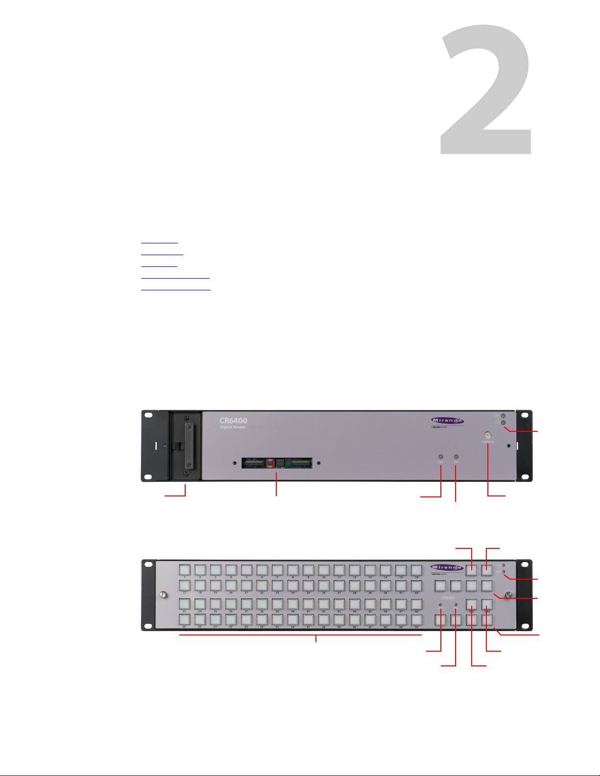
Power LEDs
Rotary Switch
Reference LED
Fan LED
Connectors
(Removable) Fan Unit
Power LEDs
Panel LockDest. Lock
Selection Buttons (64)
Level
Select (4)
Dest. Mode
Source Mode
Unused (4)
Fan LED
Ref. LED
Introduction
Chapter 2 provides a functional description of the CR6400 routers and the CP6464 control panel.
Topics
Overview . . . . . . . . . . . . . . . . . . . . . . . . . . . . . . . . . . . . . . . . . . . . . . . . . . . . . . . . . . . . . . . . . . . . . . . . . . . . . . . . . . 3
The Router
I/O Cards
The Control Panel
Feature Summary
Summary
The CR6400 family is a unique subset of Grass Valley’s CR series of compact routers: the family’s
routers have a larger switching matrix (64×64) and modular construction.
The CR6400 routers are 2RU routers, are about 10 inches deep.
. . . . . . . . . . . . . . . . . . . . . . . . . . . . . . . . . . . . . . . . . . . . . . . . . . . . . . . . . . . . . . . . . . . . . . . . . . . . . . . . 6
. . . . . . . . . . . . . . . . . . . . . . . . . . . . . . . . . . . . . . . . . . . . . . . . . . . . . . . . . . . . . . . . . . . . . . . . . . . . . . . . . . 9
. . . . . . . . . . . . . . . . . . . . . . . . . . . . . . . . . . . . . . . . . . . . . . . . . . . . . . . . . . . . . . . . . . . . . . . . 10
. . . . . . . . . . . . . . . . . . . . . . . . . . . . . . . . . . . . . . . . . . . . . . . . . . . . . . . . . . . . . . . . . . . . . . . . 12
A thin 2RU control panel
here:
The control panel has an array of 64 function buttons at the left and 12 function buttons at the
right. The panel’s default button functions are identified here.
— the CP6464 — can mount directly on the front of the router as shown
3
Page 14
Introduction
Control Card
I/O Card
Slots (4)
Ground Lug
Power (2)Crosspoint Card
Overview
The default functions include:
Source Mode Destination Mode Source Select Destination Select
Panel lock Destination Lock Level 1–Level 4
In the default function set, four of the buttons are unused.
When the panel is configured in CRSC (Compact Router System Configurator), all the buttons of
the panel are configurable and support salvos, which are not available in the default function
set.
At the rear, unlike other compact routers, the CR6400 has 4 slots for removable (serviceable) I/O
cards, and slots for a crosspoint card and a control card.
Because all the cards are removable, they are field-replaceable. The CR6400 routers also have a
removable fan unit, accessible through the front of the router.
The router, when it contains one or more 3Gig cards, is considered a CR6464-3Gig router and it
switches video. The router, when it contains one or more AES cards, is considered a CR6464-AES
router and it switches AES audio.
Without any I/O cards installed, the router is considered “undefined.”
At this release, the matrix size is fixed at 64×64. Each I/O card provides 16 inputs and 16 outputs.
Compact Router Background
The CR series includes 1RU and 2RU compact routers, compact control panels, and “remote
panel modules.”
The 1RU routers have switching matrices up to 16×16 and the 2RU routers (other than the
CR6400 routers) have switching matrices up to 32×32.
The CR series includes many different routers that switch different signal formats: SDI (3Gig, HD,
SD), AES, analog audio, and analog video. The CR series also includes machine control routers.
The CR series includes 3 “clean and quiet” (CQX) routers and a CQX control panel.
Please refer to the Compact Router User’s Guide for a complete list of the other compact routers
and panels, and a description of each.
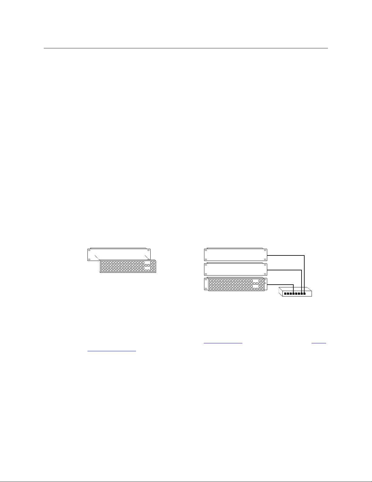
General Compact Router Usage
There are several different ways to use compact routers in general:
• As a single stand-alone router with a “captive” control panel or with automation.
• In a network of stand-alone routers, with one or more captive panels, and with or without
automation.
• In a CRSC network of routers and remote panels, with or without automation. Here, the pan-
els and routers (including CR6400 routers and panels) are configured using CRSC.
4
Page 15
CR6400
Single Standalone Router and
“Captive” Control Panel
Multiple Standalone Routers
and “Captive” Control Panel
Ethernet
User’s Guide
• In a network of routers under an NV9000 router control system.
A captive panel is one attached directly to a router. A remote panel is one mounted on a
remote panel module.
Automation is left to the customer and is not addressed in this document.
Stand-Alone CR6400 Usage
The CR6400 family routers can also be used in the following ways:
• As a single stand-alone CR6400 router with a “captive” control panel or with automation.
• In a network of stand-alone CR6400 routers, possibly with captive panels, and with or with-
out automation.
Compact routers and remote panel modules come from the factory ready for stand-alone operation. They must be configured in CRSC if they are to be used either in a CRSC network or in an
NV9000 network. Once configured, they must be reset to their factory default state to operate in
stand-alone mode.
A remote panel module must be configured to operate (1) in a CRSC network or (2) in an NV9000
network. The two configuration modes are mutually exclusive.
The CR6400 routers, in their factory default state, operate in stand-alone mode (also known as
“default” mode) either as a single router or in a small network. They do not require configuration
to operate in stand-alone mode.
Figure 2-1 compares a stand-alone CR6400 with a captive panel to a stand-alone CR6400
network with a captive panel:
Fig. 2-1: Standalone CR6400s
Up to 4 CR6400 routers may be controlled with a single CP6464.
When configured in CRSC, the CR6400 routers and remote panel modules can operate in CRSC
network mode or NV9000 network mode. See CRSC Networks
Network Operation (page 49).
Software
CRSC (Compact Router System Configurator) is a configuration and monitoring tool for compact
routers and remote panel modules.
CRSC is also an essential tool for performing firmware updates for all CR Series products.
on page 25 and Chapter 6, CRSC
5
Page 16
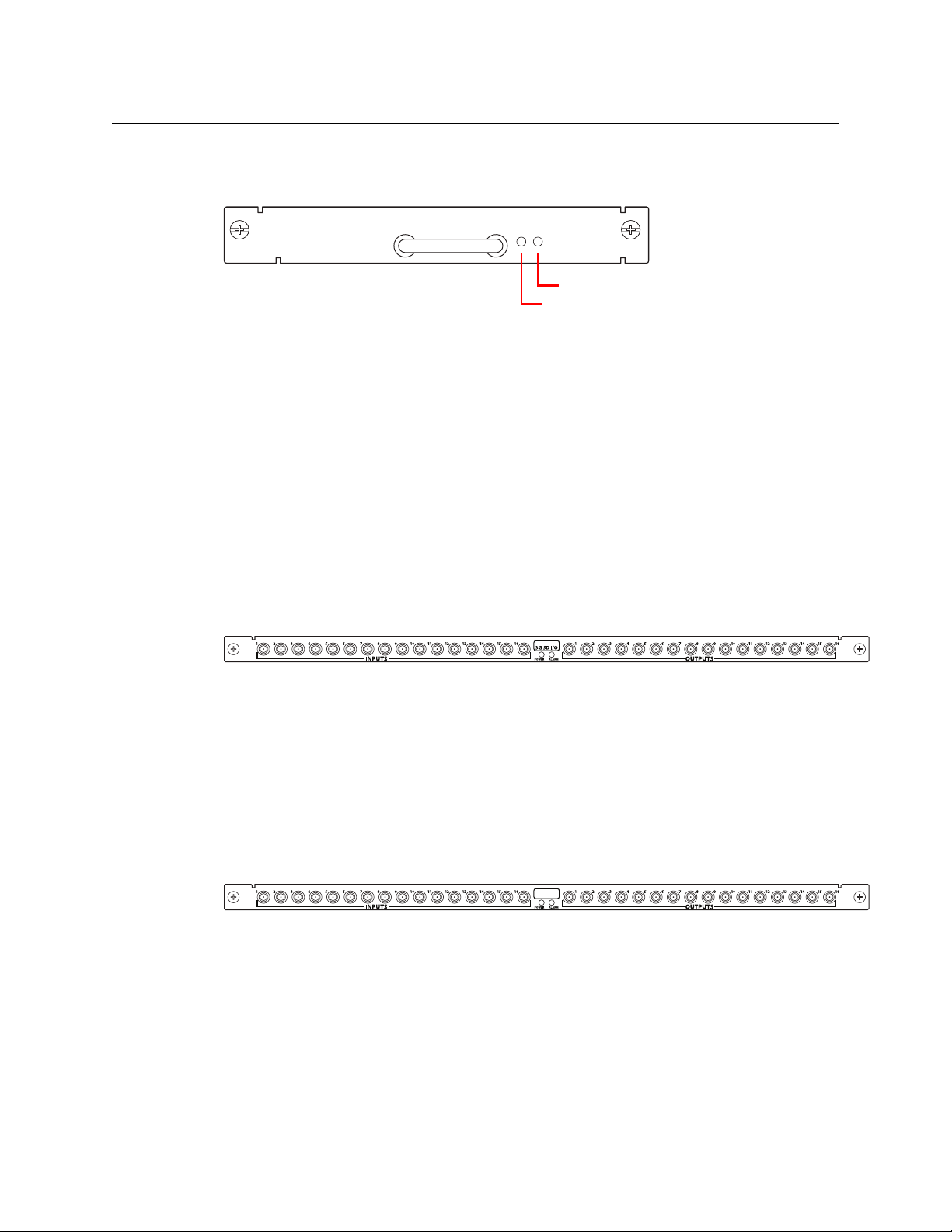
Introduction
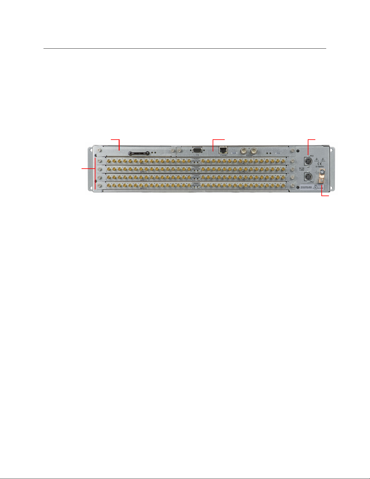
Power
LEDs
Rotary Switch
Reference LED
Fan LED
Connector Cover Plate
(Removable) Fan Unit
Control CardCrosspoint Card
I/O Card
Slots (4) Ground
Lug
Power (2)
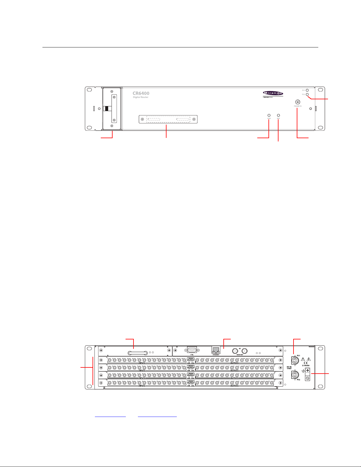
The Router
The Router
The CR6400 routers are 2RU routers. They are about 10” deep to accommodate removable I/O
cards. This is a front view of the router:
The CR6464-3Gig and the CR6464-AES routers have the same features at the front. The two
routers are distinguished, at the rear, by the labeling on their I/O cards.
The router’s fan module is removable through the front of the router.
You can mount a CP6464 control panel on the front of the router. The router has a connector
that mates to the panel. If a panel is not attached to the router, a small metal plate covers the
connector opening.
At the right side of the front of the router is a 16-position rotary switch. The positions are labeled
0–F in hex (equivalent to 0–15 in decimal). Turning this switch to different positions on different
routers (1) assigns “levels” to the routers, and (2) determines the IP addresses of the routers in a
network of routers.
Powering up the router with the rotary switch set at its 0 position causes the router to be
reset to its factory defaults. (You should not use the router in your system with its switch at
the 0 position.)
Two power LEDs give the status of the router’s two power supplies. The LEDs will be illuminated
if the power supplies are functioning properly.
The fan LED shows red if a problem exists in the fan module and green otherwise. The fan
module has two fans. If one fails, the fan LED turns on. The other fan can provide enough air
movement to cool the router.
The reference LED shows green when the router is receiving a good video reference signal and
red when it is not.
At the rear, the CR6400 routers have 4 slots for removable I/O cards, and slots for a crosspoint
card and a control card (also called a CPU card).
The control card has several connectors and 2 LEDs: an alarm LED and a power LED. The crosspoint card has no external connectors, but does have an alarm LED and a power LED.
See Control Card
6
and Crosspoint Card, following.
Page 17
CR6400
64 64
μP Logic
Inputs
(Equalized)
Outputs
(Reclocked)
Crosspoint
Switch
Control
Panel
Video
Reference
Automation
Ethernet
(optional)
Serial (DE9) Ethernet (RJ-45) Video Ref (BNC, 75W) Alarm LED
Power LED
User’s Guide
Each I/O card has 32 ports. There are 16 input ports on the left (as you face the rear of the router)
and 16 outputs on the right. The connectors for both the 3Gig card and the AES card are DIN 1.0/
2.3 connectors (which we usually call “coax” connectors).
The I/O cards are not configurable in any way, apart from their presence or absence in the router.
The crosspoint card is not configurable and the control card is not configurable.
At this revision, the router must contain only 3Gig cards or only AES cards. It contains 4 cards. If
the router is populated with 3Gig cards, the router is considered a CR6464-3Gig and switches
video. If the router is populated with AES cards, the router is considered a CR6464-AES and
switches audio. A router frame having no cards is considered of “undefined” type.
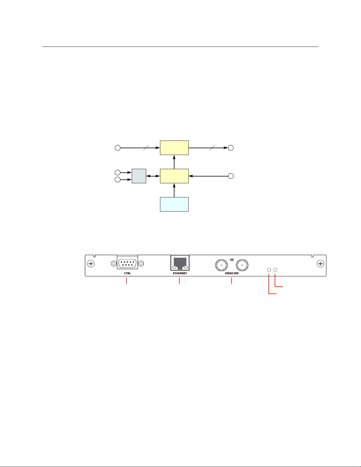
Figure 2-2 shows a simplified block diagram of a CR6400 router:
Fig. 2-2: Block Diagram of the CR6400
Control Card
The control card (also called the CPU card) is the heart of the router:
These are its functions:
• Receive button presses made at the panel and send status (button illumination) to the panel.
• Implement the “architecture” of the router.
• Receive reference video.
• Maintain buffer for video timing with respect to the video reference.
• Execute switches (with respect to the video reference) and perform locks and unlocks.
• Read the rotary switch at startup.
• Communicate with an automation or control system
• Communicate with other CR6400 family routers over Ethernet.
7
Page 18
Introduction
51
69
Gnd
TX–RX+
Gnd
n.c.
Gnd
TX+RX–
Gnd
The Router
Ports
The control card has several ports:
Serial P
ort Ethernet Port Video Reference
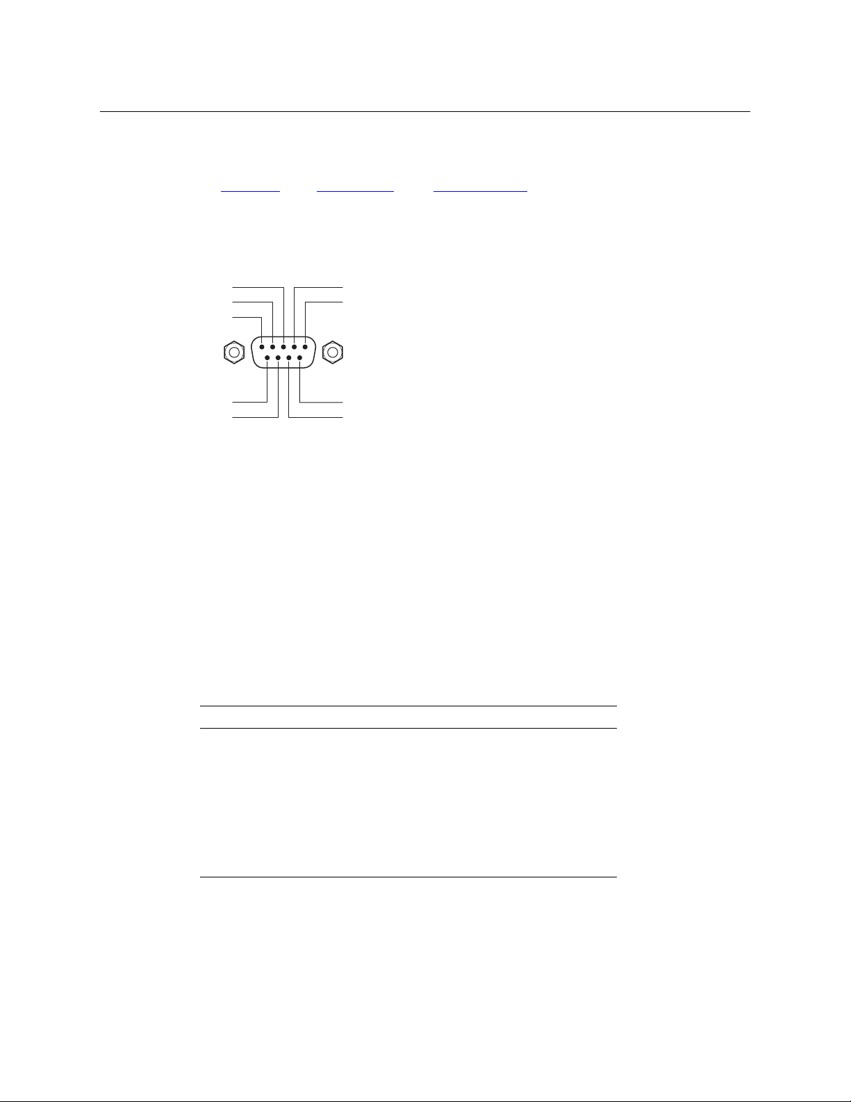
Serial Port
The serial port uses a DE9 connector, and supports RS-422 or RS-485 protocol. This is the pinout
of the port:
The serial port allows access to an automation system that uses NVISION serial protocol.
Ethernet Port
The Ethernet port has an RJ-45 connector. The CR6400 routers communicate with other CR6400
routers through this port. It is also through the Ethernet port that CRSC (on your PC) communicates with the router.
The protocol is UDP as for all compact routers.
Video Reference
The video reference ports (2 BNCs) provide loop-through, where you connect your video reference to either video reference connector and use the other video reference connector to feed
the reference signal to another device. The reference signal must be terminated using a 75W
terminator.
The CR6400 accepts these video reference rates:
Composite HD Tri-level
525i / 59.94
(NTSC)
625i / 50
(PAL)
720p / 23.98
720p / 24
720p / 25
720p / 29.97
720p / 30
720p / 50
720p / 59.94
720p / 60
1080i / 47.95
1080i / 48
1080i / 50
1080i / 59.94
1080i / 60
1080p / 23.98
1080p / 24
1080p / 25
1080p / 29.97
1080p / 30
1080p / 50
1080p / 59.94
1080p / 60
Other Features
The power LED is green when the control card has good power, and red if power is faulty.
The alarm LED is red when an alarm condition exists (such as the absence of a video reference).
The alarm LED is green otherwise.
(Of course, both LEDs are off when there is no power.)
8
Page 19
I/O Cards
Alarm LED
Power LED
CR6400
AES I/O
CR6400
CR6400
User’s Guide
Crosspoint Card
The crosspoint (XPT) card contains the switching matrix:
There are no connectors on the XPT card, but it does have an alarm LED and a power LED.
The power LED is green when the control card has good power and red if power is faulty.
The alarm LED is red when an alarm condition exists (such as the absence of a video reference).
The alarm LED is green otherwise.
The I/O cards are labeled according to their type and have an alarm LED and a power LED.
The power LED is green when the control card has good power and red if power is faulty.
The alarm LED is red when an alarm condition exists (such as the absence of a video reference).
The alarm LED is green otherwise.
3Gig
The 3Gig card has 16 “coax” inputs and 16 coax outputs:
The “3Gig” I/O cards support video, with or without embedded audio, at 2.966Gb/s, and
2.97Gb/s video rates as well as a number of HD and SD bit rates and formats. The 3Gig cards
reclock at 270Mb/s, 1.483Gb/s, 1.485Gb/s, 2.966Gb/s, and 2.97 Gb/s. The 3Gig cards bypass reclocking for other rates. Video reference must be nominally 800mV p-p and bi-level or tri-level in
nature.
The 3Gig cards also support DVB-ASI.
AES
The AES card has 16 “coax” inputs and 16 coax outputs:
The AES router switches AES3id audio.
Each of the 64 AES inputs is a stereo pair. Similarly, each of the 64 AES outputs is a stereo pair.
The inputs are switched as stereo pairs. There is no other switching option for the CR6464-AES
routers.
9
Page 20
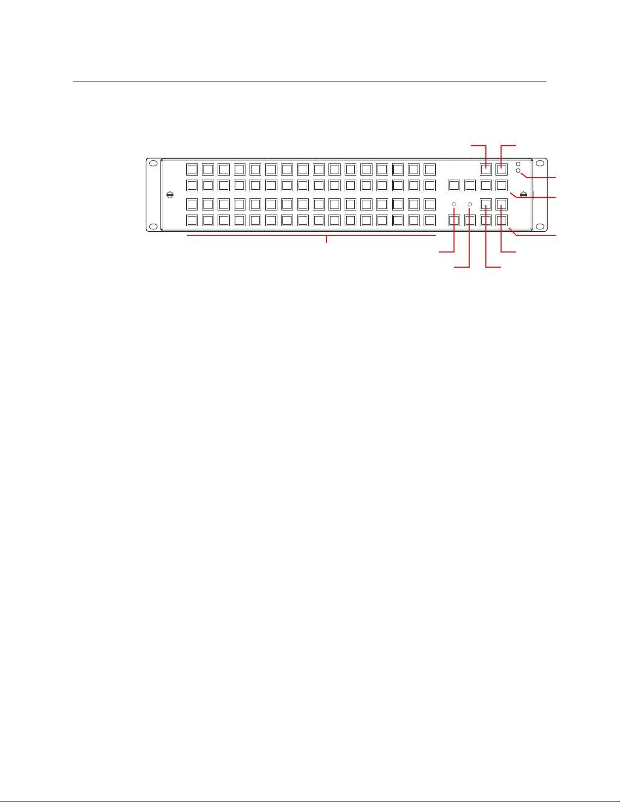
Introduction
Power
LEDs
Panel LockDest. Lock
Selection Buttons (64)
Level
(1–4)
Dest. Mode
Source Mode
Unused (4)
Fan LED
Ref. LED
The Control Panel
The Control Panel
A thin 2RU control panel — the CP6464 — can mount directly on the front of the router as shown
here:
The control panel has an array of 64 device selection buttons at the left and 12 function buttons
at the right. The panel’s default button functions are shown here. The default functions include:
Source Mode Destination Mode Source Select Destination Select
Panel lock Destination Lock Level 1–Level 4
In the default function set, four of the buttons are unused.
When a remote panel module is configured in CRSC (Compact Router System Configurator), all
the buttons of the associated panel are configurable and include salvos, which are not available
in the default function set.
8
9
7
A
B
6
C
5
4
D
E
3
2
F
0
1
Default Button Functions
When coupled with stand-alone routers, the panel has a default button set. These are the
button functions:
• Level 1–Level 4. These 4 buttons enable switching on (up to) 4 routers in a network. Each
router is considered a level. Typically, levels are used to organize the switching of different
signal types.
In a router network, signals are switched according to which levels are selected using the
level buttons. If a level is unselected, switching on that router is disabled.
If the panel is controlling a single router, and the router’s rotary switch is set to position 1, 2,
3, or 4, the matching level button will be illuminated but disabled because it is not needed.
• Panel Lock. Prevents accidental use of the entire panel.
The panel lock button, normally low-tally green, goes high tally red when the panel is
locked. All other buttons become disabled until the operator presses the panel lock button
again to unlock the panel.
• Destination Lock. Prevents takes to one or more destinations.
The destination lock button, normally amber, goes high tally red when the currently selected
destination is locked. When a destination is locked, the destination button turns high tally
red
— as a warning — if you press it.
If you have two or more routers in a network, destinations are locked on selected levels.
A destination button might indicate a lock or might not, depending on the levels the
operator has selected.
10
Page 21

CR6400
User’s Guide
• Destination Mode.
The destination mode button enables destination selection using the array of selection buttons.
When a panel operator presses the destination selection button, we say the panel is in destination mode. The 64 selection buttons turn amber and permit the selection of one of 64 destinations.
• Source Mode.
The source mode button enables source selection using the array of selection buttons.
When a panel operator presses the source selection button, we say the panel is in source
mode. The 64 selection buttons turn green and permit the selection of one of 64 sources.
Stand-Alone Definitions
The terms source and destination have specific meaning with respect to routers.
In general, a source is a set of associated input ports and a destination is a set of associated
output ports. (The source’s inputs connect to a device at which a signal originates. That can be
called a source device. A destination’s outputs connect to a device to which you are sending the
signal and that can be called a destination device.)
A level is the set of signals that are routed by one router. A network of 4 routers therefore has 4
levels — one for each router.
Breakaway is defined as a route in which a destination receives input from different sources on
different levels.
For a Single Router
1 A source is an input (i.e., a connector) on the CR6400 router.
2 A destination is an output (i.e., a connector) on the CR6400.
(When you have just a single router, the set of inputs for a source is just a single port and the set
of outputs for a destination is just a single port.
For a Router Network (Up to 4 Routers)
1A source is set of N inputs on the routers in the network, where N is the number of routers. A
source comprises the same input on all N routers. (All levels are included in the source).
Example: in a network of 3 routers, source 5 is the set of input 5 on router A, input 5 on router
B and input 5 on router C.
2A destination is set of N outputs on the CR6400s in the network, where N is the number of
routers. It is the same output on all N routers. (All levels are included in the destination).
3 If the operator routes source J to destination K, then input J on all routers is taken to output
K on all enabled levels. (A level — i.e., a router — is enabled when a level button on a CP6464
panel selects it.)
4 Breakaway can occur by choosing different levels for separate takes to the same destination.
(The concept of breakaway is undefined for a single router.)
11
Page 22

Introduction
Feature Summary
Stand-Alone Button Color
A panel’s buttons have color: green, amber, red and are either bright (high-tally), dim (low-tally),
or off (disabled). Buttons go high-tally when selected (pressed) and remain low-tally when they
are not selected. In general, green means source and amber means destination. These colors
have other meanings, however.
If a selection button is red when the panel is in destination mode, the destination is locked on
the selected levels. The destination lock button will also be red in that case. The selection button
is high-tally red when that destination is selected and low-tally red when some other destination is selected.
The panel lock button turns red when the panel is locked.
Operating a control panel (at first release) is very simple. See Chapter 5, Stand-Alone O
on page 41.
Buttons are not labeled at the factory. If you want button legends, you must create your
own. See Button Legends
Feature Summary
peration
on page 24.
Router
The CR6400 has the following features and characteristics:
• Two power connections for redundancy. The routers have 2 indicator LEDs, one for each
power supply.
• One Ethernet port, supporting network operation.
• One copper grounding terminal.
• One 16-position rotary switch used to specify the level of a router. The router’s IP address is
also derived from the switch setting.
• Quick and easy control panel mounting.
• Non-volatile memory. Routes (and IP addresses) are preserved if power is shut off.
• One RS-422/RS-485 port, for connection to an automation system or control system.
• Four I/O card slots.
At first release, the I/O cards must be all AES cards or all 3Gig cards.
Each card has an alarm LED and a power LED.
• One pair of video reference connectors (BNC, 75 W, loop-through).
• An LED indicates whether the router has video reference. Another LED provides fan status.
Control Panel
A control panel can operate in stand-alone (or default, or factory-default) mode or can operate
in CRSC mode, in a CRSC network or an NV9000 nework.
(In a CRSC network, only panels mounted on remote panel modules are configurable. Panels
mounted on routers — “captive” panels — function in default mode, are not configurable, and
have limited capabilities.)
12
Page 23

CR6400
User’s Guide
Stand-Alone Mode
In stand-alone operation, the CP6464 has the following characteristics:
• The meaning of I/O buttons is fixed and the mapping of buttons to I/O connectors is fixed.
The set of 64 buttons represents sources when the source mode button is pressed and represents destinations when the destination mode button is pressed.
• Function buttons:
The Panel Lock button is normally low-tally green. It turns bright red when the panel is
locked.
The Destination Lock button is normally low-tally amber. It turns bright red when a selected
destination is locked (unless none of the destination’s levels are selected).
The 4 buttons (immediately below the lock buttons) select levels 1 to 4, in that order.
Pressing the source mode button makes the selection buttons (or I/O buttons) turn green
(high- or low-tally) In source mode, the selection buttons select sources.
Pressing the destination mode button makes the selection buttons (or I/O buttons) turn
amber (high- or low-tally) In destination mode, the selection buttons select destinations.
Other function buttons are reserved for future use.
• Each button has a clear plastic cap that can be easily removed to accommodate customer-
defined button legends.
• Two LEDs indicate whether the power supplies of the router on which the control panel is
mounted are connected and functioning.
• An LED indicates whether the router has reference. Another LED provides fan status.
• A control panel mounts easily and quickly on the router with two knurled screws and electri-
cal connectors. The CR6400 routers have two connectors. The CP6464 presently has one
connector that mates to one of the connectors on the router.
CRSC Mode
These are the panel’s chararistics in CRSC mode:
• The meaning of I/O buttons is completely configurable and the mapping of buttons to I/O
connectors is also configurable.
• Function buttons:
The ‘Panel Lock’ button is normally low-tally green. It turns bright red when the panel is
locked.
The ‘Destination Lock’ button is normally low-tally amber. It turns bright red when a selected
destination is locked (unless none of the destination’s levels are selected).
There are several “paging” button types that can be configured on the panel. These select
which subset of button functions appear on the matrix of 64 buttons.
A source button is green (high- or low-tally).
A destination button is amber (high- or low-tally).
Panels may have salvo buttons.
13
Page 24

Introduction
Feature Summary
• Each button has a clear plastic cap that can be easily removed to accommodate customer-
defined button legends.
• Two LEDs indicate whether the power supplies of the router on which the control panel is
mounted are connected and functioning.
• If the panel is mounted on a router, an LED indicates whether the router has reference.
Another LED provides fan status. When the panel is mounted on a remote panel module,
those LEDs have no function. (There is no fan in the remote panel module and the remote
panel module takes no reference signal.)
• A control panel mounts easily and quickly on a router or remote panel module with two
knurled screws and electrical connectors.
(In a CRSC network, only panels mounted on remote panel modules are configurable. Panels
mounted on routers — “captive” panels — function in default mode and have limited use.)
See CRSC Networks
on page 25 and Chapter 6, CRSC Network Operation (page 49).
14
Page 25

Chapter 3 provides installation instructions.
Topics
Package Contents . . . . . . . . . . . . . . . . . . . . . . . . . . . . . . . . . . . . . . . . . . . . . . . . . . . . . . . . . . . . . . . . . . . . . . . . 15
Design Considerations
Rack Mount
C
reating a Router Network . . . . . . . . . . . . . . . . . . . . . . . . . . . . . . . . . . . . . . . . . . . . . . . . . . . . . . . . . . . . . . . 18
Tes ti ng
. . . . . . . . . . . . . . . . . . . . . . . . . . . . . . . . . . . . . . . . . . . . . . . . . . . . . . . . . . . . . . . . . . . . . . . . . . . . . . 17
. . . . . . . . . . . . . . . . . . . . . . . . . . . . . . . . . . . . . . . . . . . . . . . . . . . . . . . . . . . . . . . . . . . . . . . . . . . . . . . . . . . 20
Package Contents
If you have ordered CR6400 routers (and products related to them) from Grass Valley, you
should inspect the shipping container for damage. If you find any container damage, unpack
and inspect the contents. If the contents are damaged, notify the carrier immediately.
As you unpack the shipping container, look for the packing slip and compare it against the
contents to verify that you received everything as ordered. If anything is missing (or if you find
equipment damage unrelated to shipping), please contact Grass Valley.
Depending on your order, the items that can ship include:
• One or more routers. The router’s crosspoint card and control card will have been inserted in
their respective slots.
• I/O modules (inserted in I/O slots of the router).
• A shielded Ethernet cable (7’, about 2 m, for each router).
• One or more control panels.
• One or more power supplies.
• User’s guides (this document in particular), router firmware, CRSC configuration software,
and button legend templates in different file formats, on a CD.
• A quickstart guide (hard copy).
Other than the 7’ shielded Ethernet cable, the package does not contain network cables, video
cables, BNC terminators, mounting screws, or grounding wire.
There are no special precautions regarding ESD.
This document does not address the shipment or installation of any other equipment or software that can be used in conjunction with the CR6400 family products.
Installation
. . . . . . . . . . . . . . . . . . . . . . . . . . . . . . . . . . . . . . . . . . . . . . . . . . . . . . . . . . . . . . . . . . . . 16
15
Page 26

Installation
Design Considerations
Design Considerations
By the time you are ready to install your equipment and software, you (or someone in your organization) will have already made most of the system design decisions. In fact, the design
decisions will have been made before the equipment is ordered. The following is a review of the
concepts.
Stand-Alone CR6400 Routers
A single CR6400 router operates in stand-alone mode with an attached (or “captive”) control
panel. A single stand-alone router will work reliably and operation is extremely simple.
The single CR6400 can switch signals according to the type of I/O cards installed in the 4 slots at
the rear of the router. The CR6464-3Gig switches video; the CR6464-AES switches audio.
Stand-Alone CR6400 Networks
A stand-alone network includes 1–4 routers and one CP6464, mounted on one of the routers.
Additional CP6464s could be mounted on the other routers, but they would provide little or
no additional capability.
Each router in the network is considered a level. The levels are numbered and the level numbers
range from 1 to 4. The routers can be switched either independently or simultaneously for
multi-level takes.
The term level, in a stand-alone network, means little more than a router number.
CRSC Networks
A CRSC network includes a number of CR Series routers and panels of any type, all of which have
been configured in CRSC.
(It is actually remote panel modules that are configured, not the panels themselves.)
See CRSC Networks
In CRSC, nearly every button of a control panel can be configured. Panels do not exhibit or rely
on factory default behavior. (Salvo buttons are also available.)
Under CRSC, a level is a router partition. Up to 8 levels can be defined in a CRSC network.
Under CRSC, the mapping of inputs and outputs to sources and destinations is completely
configurable.
(In a CRSC network, only panels mounted on remote panel modules are configurable. Panels
mounted on routers — “captive” panels — function in default mode and have limited use.)
on page 25 and Chapter 6, CRSC Network Operation (page 49).
NV9000 Networks
CR Series routers and panels can also be deployed in an NV9000 network. CR Series remote
panel modules must be set up (in CRSC) to function in NV9000 networks.
A remote panel module must be given a panel ID and configured in NV9000-SE Utilities.
NV9000-SE Utilities is the configuration software for NV9000 router control systems.
NV9000-SE Utilities communicates with routers using specific router protocols. For CR Series
routers, the protocol to use is ‘NV Compact Router Ethernet’.
16
Page 27

Rack Mount
The CR6400 routers are designed to mount in a 19” rack. Rack-mounting is not a requirement,
but we assume a 19” rack for the sake of simplicity.
Follow these steps to install a CR6400 router:
1 Set the position of the 16-position rotary switch on the front of the router. (It is not on the
2 If the router is to have a CP6464 control panel, place the panel on the front of the router,
3 Mount, and secure, the router assembly in the rack.
4 If you are using the router on a network, connect the supplied Ethernet cable (RJ-45) from
5 Optionally, connect your video reference.
6 Optionally connect the ground lug to earth ground. Use copper wire from 14 to 6 AWG.
7 Connect one or both power supplies.
CR6400
User’s Guide
control panel. If the control panel is mounted on the router, you must detach the control
panel from the router to access the rotary switch.)
If you have a single CR6400 router, set the switch to any non-zero position.
If you have more than one CR6400 router, their rotary switches must be set to positions in
the range 1–4. The switch positions for the routers must all be different.
Refer to Levels and IP Addresses in Stand-Alone Networks
how the rotary switch is used.
Use a small slotted screwdriver to turn the rotary switch.
mating the electrical connector on the panel to the electrical connector on the router. The fit
requires only minimal force. Tighten the knurled screws that secure the control panel to the
router. Tabs at the ends of the control panel fit in slots in the face of the router, helping you
align the panel to the router.
As you install the panel, its buttons might flicker until you secure the panel in place. This is
harmless.
You may install a control panel’s button legends at any time. See Button Legends
page 24.
The CR6400 router’s mounting holes on each side are spaced 3” (76 mm) vertically and allow
approximately 1/8” (3mm) of play horizontally.
Position the router so that its mounting holes are aligned with the holes in the rack. Use 4
screws to secure the router to the rack.
the network switch to the Ethernet port of the router.
See C
reating a Router Network, on page 18.
SDI signals require a reference to perform switches in accordance with SMPTE RP168.
The router has two video reference BNC connectors. You can connect the reference source to
either one. If you have more than one router, you can “daisy chain” the output of one reference connector to the input of another. The output of the last connector in the series should
be terminated with a 75W BNC terminator.
Grounding decisions are left to you or your facilities manager. Failure to connect the ground
will not affect normal operation, but connecting the ground will protect you and your equipment in a power anomaly such as a lightning strike.
, on page 19 for information on
on
17
Page 28

Installation
Creating a Router Network
The external power supplies are described in Power Specifications on page 77. Each connector has 4 pins.
The enclosing ring of the cable connectors are connected to ground. Be careful not to
Always disconnect the power supply from AC power before connecting the power
See Trouble-Shooting
panel) fails to light.
8 Connect input devices and output devices. The exact connections are, of course, determined
by the requirements of your system.
The AES and 3Gig cards have DIN 1.0/2.3 connectors. Depending on the devices you are connecting to your router, you might need to obtain BNC-to-DIN adapter cables.
Following are recommended practices for installing CR6400 routers:
• If the router is installed in a closed or multi-unit rack assembly, the operating ambient tem-
perature of the rack environment may be greater than room’s ambient temperature. Install
the router in an environment compatible with the maximum ambient temperature (Tma)
specified for the router.
• Install the router in a rack so that the amount of air flow required for safe operation of the
router is not compromised.
• Mount the router in the rack so that a hazardous condition does not arise from uneven
mechanical loading.
• Connect the router to your supply circuit with consideration of the effect that overloading
the circuits might have on overcurrent protection and supply wiring. Observe the nameplate
ratings when addressing this concern.
• Maintain reliable earthing (grounding) of rack-mounted equipment. Give particular atten-
tion to indirect supply connectionssuch as power strips.
short the power pins (+48V) to the ring.
supply to the router. Then reconnect AC power to the power supply.
on page 75 if the power LED on the front of the router (or control
Creating a Router Network
A router network is necessary if you wish to perform multi-level takes and locks. Otherwise, a
single stand-alone router is sufficient.
A CRSC network is required if you want configurable router levels, configurable IP addresses, or
configurable button panels.
A stand-alone CR6400 network is sufficient if you don’t require a CRSC network.
Stand-alone networks are discussed here. See CRSC Networks
Network Operation (page 49).
18
on page 25 and Chapter 6, CRSC
Page 29
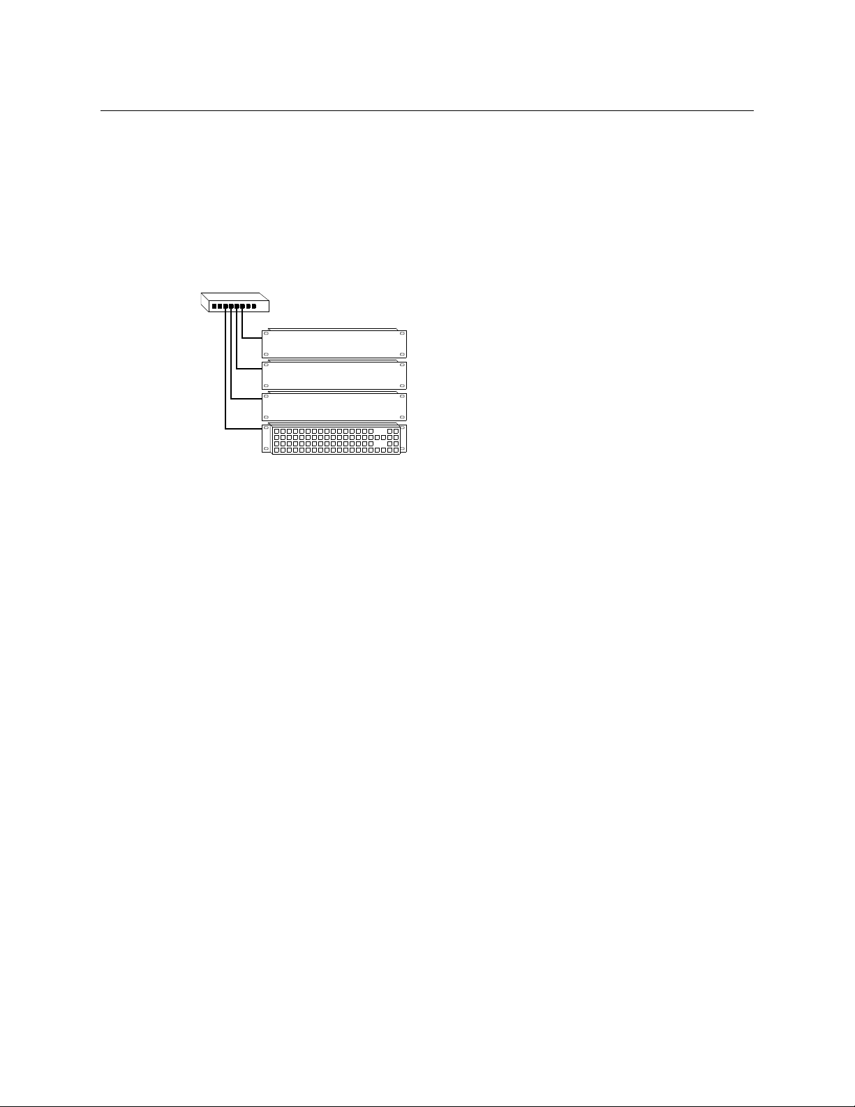
CR6400
Router 1
Router 2
Router 3
Router 4, with captive panel
Ethernet Switch
User’s Guide
Stand-Alone Networks
A stand-alone CR6400 network comprises the following items:
• From 1 to 4 CR6400 routers.
• A CP6464 panel.
• An Ethernet switch capable of 100MB/s operation with enough ports to accommodate your
routers.
Figure 3-1 shows a stand-alone network of CR6400 routers:
Fig. 3-1: Network of Routers
The panel can switch signals on the 4 routers (if they are correctly set up). Each router is considered a level. The panel operator selects levels using the level buttons on the panel. Takes occur
only on selected levels. (However, if no levels are selected, the result is as if all levels are
selected.)
Levels and IP Addresses in Stand-Alone Networks
Each CR6400 router in the network is considered equivalent to a level. Each router requires an IP
address. Use the 16-position rotary switch on the front of a router to set its IP address and corresponding level:
Level = switch value (1–4).
address = switch value + 100.
The IP address is 192.168.2.address.
Thus, subnet addresses for routers range from 101 to 104 and correspond to the router levels.
The numbers on the rotary switch are in hexadecimal: 0–F.
If the switch is at setting 0, the router will reset to its factory state, losing crosspoint values.
You should avoid leaving the switch at setting 0.
19
Page 30

Installation
Testing
Testing
If your system fails in any way, please refer to Trouble-Shooting, on page 75.
Stand-Alone Router
A stand-alone CR6400 router is a single router that is not connected to a network and (presumably) has a captive panel mounted on the front.
The router’s rotary switch must be set to a value in the range [1–4].
The panel will power up in the locked state. The ‘Panel Lock’ button will be red. Just press the
red button to clear the lock.
1 Ensure that the router has power. Either or both of the power indicator LEDs should be on.
If that is not the case, then check the power indicator LED of the router’s power supply and
check the connectors of the power supply’s cables. Replace the power supply if it is defective.
You might want to use the power supply strap to help the line cable secure. See Power Cord
Retention for the PS0012 Power Supply on page 89.
2 Examine the captive panel. Are all the selection buttons illuminated? (Most will be low-tally.)
Some of the function buttons (at the right) will be illuminated and some will not.
3 Perform one or more takes using the panel.
(Press the destination mode button followed by a selection button. Then press the source
mode button followed by a selection button.)
You do not need to connect any devices to a router to see whether it switches, but it helps in
testing if you do. Button status on the control panel reflects the router’s state. However, connected devices will give you visual and auditory feedback regarding the quality of the
switched signals.
4 Perform a panel lock. Press the panel lock button and it should turn red. (When the panel is
locked, other buttons are disabled.)
5 Perform a destination lock. Select a destination then press the ‘Destination Lock’ button.
Both buttons should turn red. Press the ‘Destination Lock’ button again. Both buttons
should revert to amber.
6 Exactly one of the level selection buttons should be bright. The other level buttons should
be off. (There are 4 level buttons; the high-tally button corresponds to the level you configured with the rotary switch.)
If no level selection button is lit, you might have set the router’s rotary switch to a posi-
tion other than 1–4.
If the router and panel pass all of these simple tests, it is likely to be working properly. You can
now proceed with I/O connections and more exhaustive and detailed testing that is dependent
only your installation.
Report any failures to Grass Valley customer service.
20
Page 31

CR6400
User’s Guide
Stand-Alone Network
A stand-alone network comprises 1–4 CR6400 routers, a CP6464, and an Ethernet switch.
1 Ensure that each router has a unique rotary switch setting in the range 1–4. The switch posi-
tion determines the router’s level.
2 Connect and power-up your Ethernet switch. Verify that the switch is operating and that all
ports are communicating. You should see both green and amber communication lights at
the Ethernet connectors of the routers.
3 Your panel should power up with its panel lock button high-tally red. Press the panel lock
button to turn panel lock off. The panel’s buttons should become illuminated and operable.
4 If you have set the rotary switches of your routers correctly, one or more of the level buttons
should be illuminated. Level button 1 (the left-most level button) corresponds to the router
whose rotary switch was set to 1. Level button 2 corresponds to the router whose rotary
switch was set to 2, and so on.
Report and correct any failures before proceeding.
Further Testing
Perform a few multi-level takes and locks. See Chapter 5, Stand-Alone Operation, for
instructions.
Report failures to Grass Valley customer service.
21
Page 32

Installation
Testing
22
Page 33

Configuration
Chapter 4 provides configuration instructions for the CR6400 routers and the CP6464 panel.
Topics
Stand-Alone Routers . . . . . . . . . . . . . . . . . . . . . . . . . . . . . . . . . . . . . . . . . . . . . . . . . . . . . . . . . . . . . . . . . . . . . . 23
Stand-Alone
CRSC Networks
NV9000 Networks
There are several ways to use the CR6400 routers:
• As a single stand-alone CR6400 router with a “captive” CP6464 control panel.
• As a network of stand-alone CR6400 routers, with a captive CP6464 panel (or panels).
• In CRSC Networks. These are networks of CR Series routers of mixed type, with panels of
mixed type. The panels mount on remote panel modules all of which have been configured
for operation in the network.
• In NV9000 Networks. Routers and panels in an NV9000 router control system must be con-
figured in NV9000-SE Utilities. They must be set up for NV9000 operation, in CRSC, before
they can be configured in NV9000-SE Utilities.
CR6400 Networks . . . . . . . . . . . . . . . . . . . . . . . . . . . . . . . . . . . . . . . . . . . . . . . . . . . . . . . . . . . 25
. . . . . . . . . . . . . . . . . . . . . . . . . . . . . . . . . . . . . . . . . . . . . . . . . . . . . . . . . . . . . . . . . . . . . . . . . . . 25
. . . . . . . . . . . . . . . . . . . . . . . . . . . . . . . . . . . . . . . . . . . . . . . . . . . . . . . . . . . . . . . . . . . . . . . . 38
Stand-Alone Routers
A stand-alone router has very little to configure. This is what you can control:
• The number of power sources: 1 or 2.
• The physical input and output connections.
• The video reference.
• The IP address.
The Number of Power Sources
You can connect one or two external power supplies. The second power supply provides redundancy protection if the first malfunctions.
Follow these steps to connect a power supply:
1 Plug the 4-pin connector on the power supply into the 4-pin connector (PS1 or PS2) at the
rear of the router. There is only one way that it will fit. Do not force it.
2 Plug the AC cord into the other end of the power supply “brick” and then plug the AC plug
into an AC power outlet. There is no on/off switch.
23
Page 34

Configuration
Video Reference
Stand-Alone Routers
The Physical Inputs and Output Connections
The 3Gig and AES I/O cards have 32 DIN 1.0/2.3 connectors. (We call them “coax” connectors.) All
the inputs are on the left and all the outputs are on the right. The alarm and power LEDs (and
the card label) separate the two sections of a card.
In the 4 card slots, the inputs are numbered 1–64 as slots go from the top of the router to the
bottom. The same is true of the outputs.
Connect input devices and output devices to the router according to the requirements of your
system.
See Video Specifications on page 82 for cable length limits.
External Video Reference
The reference connectors are a pair of 75W BNCs, loop-through, on the control card:
Connect your video reference input to either video reference connector on the rear of the
router. Use the other video reference connector to feed the reference signal to another device.
Terminate the reference signal (or chain of reference signals) using a 75W terminator.
The Rotary Switch
A single stand-alone router does not use its 16-position rotary switch setting (useful only in a
network) but you should set it to a non-zero position in any case. (When the rotary switch is
zero, the router reverts to its factory-default state at power-up.)
When a control panel is mounted on a router, it conceals the rotary switch. You must remove the
control panel when you are setting the rotary switch.
Every time you change the rotary switch position, power-cycle the router.
Button Legends
You can label the control panel buttons. Use a desktop publishing program to create your own
button legends. The legends should be transparent and no larger than 0.40” × 0.40” (10mm
square). A 3/8” (9.5mm) square insert will allow a little clearance. The clear plastic material used
for overhead transparencies is suitable for printing legends.
To apply a label to a button, pull the clear plastic cap from the button, insert the label in the cap,
and replace the cap. We recommend that you not use adhesive.
Button legend templates (in Word,
documentation and software CD (SB0033) you received with your CR6400 product(s). Simply
type (or draw) the legends you want, print the page on transparent film, and cut the buttons
apart.
Note: selection buttons of the CP6464 represent both sources and destinations. Therefore
button legends must accommodate both source mnemonics and destination mnemonics.
To fit on the button and be legible, your mnemonics must be relatively short.
®
Illustrator,® and Freehand® formats) are available on the
24
Page 35

Stand-Alone CR6400 Networks
For each router, set up I/O, video reference, and power and ground connections as you would
for stand-alone routers.
IP Addresses and Levels
A stand-alone network allows up to 4 routers (levels 1–4). Decide what signal types (3Gig, AES,
etc.) you want on which levels and set the rotary switch position to configure the levels accordingly. To summarize, the switch positions of your routers must be 1, 2, 3, or 4 and they must all
be different.
See Levels and IP Addresses in Stand-Alone Networks
switch settings and subnet addresses.
CRSC Networks
CRSC networks have more capabiities than stand-alone networks because the routers and
panels are configurable. Because they are configurable, they are more flexible and offer more
choices. However, CRSC networks are more complex than stand-alone networks.
In a CRSC network, all routers and remote panel modules must be configured using CRSC.
Every CR Series device in a CRSC network requires an IP address. Under CRSC, the IP addresses
are not tied to a rotary switch position.
For routers, you must specify a level. You can assign up to 4 levels for each router, but the CRSC
network is limited to 8 levels in total. (A level is a router partition.)
For panels, you must choose an operating mode (standard, enhanced with hold, enhanced
without hold) and configure the panel’s buttons. Buttons that are to remain unused need not be
configured. There are shortcuts that make configuring panels quick and relatively easy.
During the configuration of a panel’s source and destination buttons, you will be creating a
mapping of routers’ I/O ports to source and destination buttons — for all panels in the network.
This is a non-trivial task often requiring a lot of design work.
Please refer to the CRSC User’s Guide for complete detailed information about configuring
remote panels. (This document focuses only on the CR6400 routers and panels.)
CR6400
User’s Guide
, on page 19, for information on rotary
Essential Information
A remote panel is a control panel mounted on a remote panel module.
A remote panel sends control messages to a network of routers and receive status information
from the network.
These panels are called “remote” because they need not be attached to a router and can be used
at a distance, as far as cable restrictions allow.
Te rm s
Please review the following definitions:
• An input or an output is a single port at the rear of a compact router. Different routers have
different kinds of connectors (e.g., BNC, DB25, RJ-45, “coax”).
25
Page 36

Configuration
CRSC Networks
• A source is a set of inputs on one or more routers, on one or more levels. The inputs might, or
might not, belong to a single physical device.
• A destination is a set of outputs on one or more routers, on one or more levels. The outputs
might, or might not, belong to a single physical device.
• A salvo is a sequence of primitive takes. The takes execute, in order, when a panel operator
presses a salvo button. A primitive take in a salvo comprises 3 values: level, input, and output. A primitive take routes a single input to a single output on a single level.
• The primary level is the first level defined for a particular destination.
• The precedence of level buttons depends on the location of the level buttons on the panel.
In general terms, level buttons have higher precedence if they are to the left of, or are above,
other level buttons. (Precedence governs which sources and destinations become enabled
for selection on a panel that is configured in standard mode.)
• A normal take is a non-breakaway take.
Operators control a CR6400 system using remote panels. An operator is presented with a large
and potentially bewildering array of buttons. It is the configurer’s task to produce a panel that is
easy to understand and to use:
• When your system has multiple panels, exercise caution so that you do not create panel con-
figurations that conflict with each other.
• Avoid configuring source buttons and destination buttons that do not match the actual
router connections and the numbering given by the router partitions.
• Create meaningful button legends that accurately describe what the buttons do. There are
button templates available on the installation CD (SB0033-xx).
Remote Panel Modes
Remote panels operate in one of three modes: (1) standard mode, (2) enhanced mode with
hold, and (3) enhanced mode without hold.
Standard Mode
In standard mode, takes are performed on (manually) selected levels only.
Level selection is persistent and at the discretion of the panel operator. Once the operator
makes a level selection, it remains until the operator changes the selection. The current level
selection enables some sources and destinations and disables others. The sources and destinations that are enabled depend on which level button has precedence. See Button Order
page 53 for information about precedence.
If no levels are selected, no sources or destinations are enabled. A take cannot occur.
If the panel has no level buttons, all of a destinations’ levels are always selected and all destinations are enabled.
Which level button has precedence depends on the order of level buttons on the panel and the
order in which the operator presses the level buttons. See Button Order
Standard mode allows breakaway. A breakaway is when you route to some, not all, of a destination’s levels. By default, all valid levels are automatically selected when you set up a take. By
creating a breakaway, you route only to the levels you have individually selected.
on page 53.
on
26
Page 37

CR6400
User’s Guide
Enhanced Mode (Hold and No-hold)
‘Takes’ are performed on all the levels specified by the destination.
In enhanced mode, level selection is applicable only to breakaway. Level selection governs the
selection of sources for the breakaway. All sources and destinations are always enabled.
Enhanced mode has 2 submodes:
• Hold mode — the level selection persists after the destination button is pressed (initiating a
take) and continues indefintely until the operator changes it. This allows an operator to try
different sources. To clear a breakaway, the operator starts a new normal take (non-breakaway) to that destination. See Normal Takes
on page 59.
• No-hold mode — a level selection reverts to the levels defined by the destination after the
operator presses a source button (completing a take). To clear a breakaway, either start a
new normal take to that destination or press a source without a level selection. See Normal
Tak es on page 59.
The choice between hold mode and no-hold mode is meant to accommodate operator or
administrator preferences.
Salvos
A “salvo” is a sequence of predefined (primitive or simple) takes. When you assign a salvo to a
button, an operator need only press that button to execute the entire take sequence.
Salvos do not:
• Execute source selections, destination selections, or level selection functions.
• Execute other salvos. (That is, salvos cannot be nested.)
• Contain loops or branches.
A simple take is expressed (in CRSC) as 3 values: level, input and output. These three values
uniquely define a single crosspoint in the set of routers and router partitions.
A salvo can include up to 64 primitive takes and a panel configuration can have up to 64 individual salvo buttons, subject to a limit of 1024 primitive takes in total. (Thus, your panel could
have, for example, 64 salvos of 16 takes or 16 salvos of 64 takes.) Each panel can have a different
set of salvos.
Paging
Certain CR Series control panels can have buttons that control the presence or absence of sets of
sources and destinations that can be controlled by the panel. We call these sets of sources or
destinations “pages.”
The panels that have “paging” buttons are the CP6464 and CP32-6464. These are the panels that
can control networks that include CR6400 family routers. (The CP6401 also controls CR6400
family routers but does not have paging buttons.)
See Select a paging method.
on page 32.
27
Page 38

Configuration
CRSC Networks
Panel Types for CR6400 Routers
These are the panel types available in CRSC:
CP32-6464 CP6401 CP6464
• The CP6464 is a 2RU panel capable of switching 64 sources to 64 destinations.
• The CP6401 is a 2RU single-destination panel. In CRSC, it has a single “default destination”
button in CRSC, but the actual panel has no destination buttons.
The CP6401 is an artificial panel type. There is no physical CP6401. The CP6401 is a fiction
that allows CRSC to configure a (real) CP6464 as a single-destination panel.
• The CP32-6464 is another artificial panel type. The CP32-6464 is a fiction that allows CRSC to
configure a CP3232 (2RU) in such a way that it can control the 64 sources and 64 destinations
of CR6400 routers in a network.
IP Addresses in CRSC
How to Add Routers to a Network
CRSC allows you to have any number of routers on a subnet. Although you can exploit this capability for ease of configuration, you must ensure that your compact router system observes the
network limits when it is running.
Routers from the factory are usually all set to the same subnet: 192.168.2.xxx. Routers that are
freshly reset to default also use that subnet.
Adding a router to the CR system creates a new level. Routers are assigned to a subnet and no
more than 8 levels in any single subnet are allowed.
If you add too many routers to a subnet, you will have created too many levels. However, CRSC
will not let you delete a router you just added because each router must correspond to at least
one level. To be able to remove the router, either disconnect the router physically, delete one or
more levels (other than those just added), or move the router to another subnet.
Follow these steps to add routers to your network:
1 Connect up to 4 routers to your network with unique rotary switch settings in the range 1 to
F (hex).
28
Remember to cycle power after you change a rotary switch.
However, if a rotary switch is set to zero (0), and you then power-cycle the router or
remote panel module, the device reverts to the factory default state, and loses its previously configured state.
2 Go to CRSC’s ‘CR Series Ethernet Settings’ page.
3 Verify that all routers appear in the list. Click ‘Refresh List’ if necessary.
4 For each router, click on the cell in the ‘IP Address’ column to edit the field. Enter a unique IP
address.
5 Repeat steps 1 through 4 for additional router. Remember that no more than 4 routers can
operate to a single subnet.
6Click Apply Updates to send the changes to the selected frames. Only those frames with
‘Update’ checked in the table rows are updated. The data are stored in the frames internally.
Page 39

CR6400
User’s Guide
How to Add Remote Panel Modules to a Network
Follow these steps to add remote panel modules to your network:
1 Connect up to 15 remote panel modules to the network with unique rotary switch settings
in the range 1 to F.
Remember to cycle power after you change a rotary switch.
However, if a rotary switch is set to zero (0), and you then power-cycle the router or
remote panel module, the device reverts to the factory default state, and loses its previously configured state.
2 Go to the ‘CR Series Ethernet Settings’ page.
3 Verify that all added remote panel modules appear in the list.
4 For each remote panel module, click on the cell in the ‘IP Address’ column to edit the field.
Enter a unique IP address.
5 Repeat steps 1 through 4 for additional remote panel modules.
6Click Apply Updates to send the changes to the selected frames. Only those frames with
‘Update’ checked in the table rows are updated. The data are stored in the frames internally.
Configuring a Router in CRSC
Use the ‘Router Levels’ page in CRSC to define router levels (i.e., partitions).
You can divide a router into as many as 4 partitions. (Those partitions could overlap if it would
suit your system design.)
Every router is at least one level.
There can be as many as 8 levels on any single subnet. To work with the routers on a subnet, you
must choose an “active subnet.”
Active Subnet
CRSC detects all subnets for which there are connections in your configuration PC. You can
place different CR Series devices on different subnets and use any available subnet you want.
Choose the subnet from the ‘Active Subnet’ drop-down list.:
The page refreshes its lists of levels after you choose a different subnet.
The designation “active” applies only in CRSC itself: it is the subnet you are configuring. In the
actual network, all subnets operate independently and concurrently.
How to Update a Level
1 In the ‘Setup Crosspoint Ranges for Levels’ table, locate the row listing the level you want to
change.
2 Optionally, in that row, click in the ‘Level Number’ or ‘Level Name’ cell to activate the field
and enter new values. Level numbers must be unique and in the range 1 to 250. Level names
are limited to 16 characters.
29
Page 40

Configuration
CRSC Networks
3 Define the physical start and end numbers for the level. These numbers identify physical
connections on the router. The numbers you enter will of course depend on what you want
to do with the router.
The default level for the router covers the entire span of inputs and outputs. For example,
the default values for a 64×64 router are
input start = 1, input end = 64,
output start = 1, output end = 64.
4 If you have remote panel(s) in your system, you might need to specify ‘Controller Input Start’
and ‘Controller Destination Start’ values for the level.
Click a field to enter a value in the field.
(The controller end values are derived from the controller start fields and the physical start
and end fields. Therefore, you cannot enter controller end values.)
5 When you have finished changing level data, click Update Router Levels to send the level
configuration data to the applicable routers. You should see a confirmation message:
Note that the ‘Update Router Levels’ button updates only the levels that were changed.
Other levels remain unaffected. .
How to Add a Level
1 Go to the ‘Configure Router Levels’ page.
2 Optionally, select the subnet on which you want to add routers levels.
3 Click the Add Level . . . button.
If your subnet has more than one router, a dialog appears:
Choose a router from the drop-down list and click OK. (The routers you choose are those
that exist in the selected subnet.)
If your subnet has no routers, you will receive a message stating that CR6400 cannot create
levels where there are no routers.
If your subnet has more than 8 levels, you will receive a message stating that a subnet cannot have more than 8 levels.
4 If there were no failures in step 3, CR6400 creates a new level, with a new (unique) level num-
ber for the router you chose.
If your subnet has only a single router, CR6400 simply adds a level identical to the existing
level.
30
Page 41
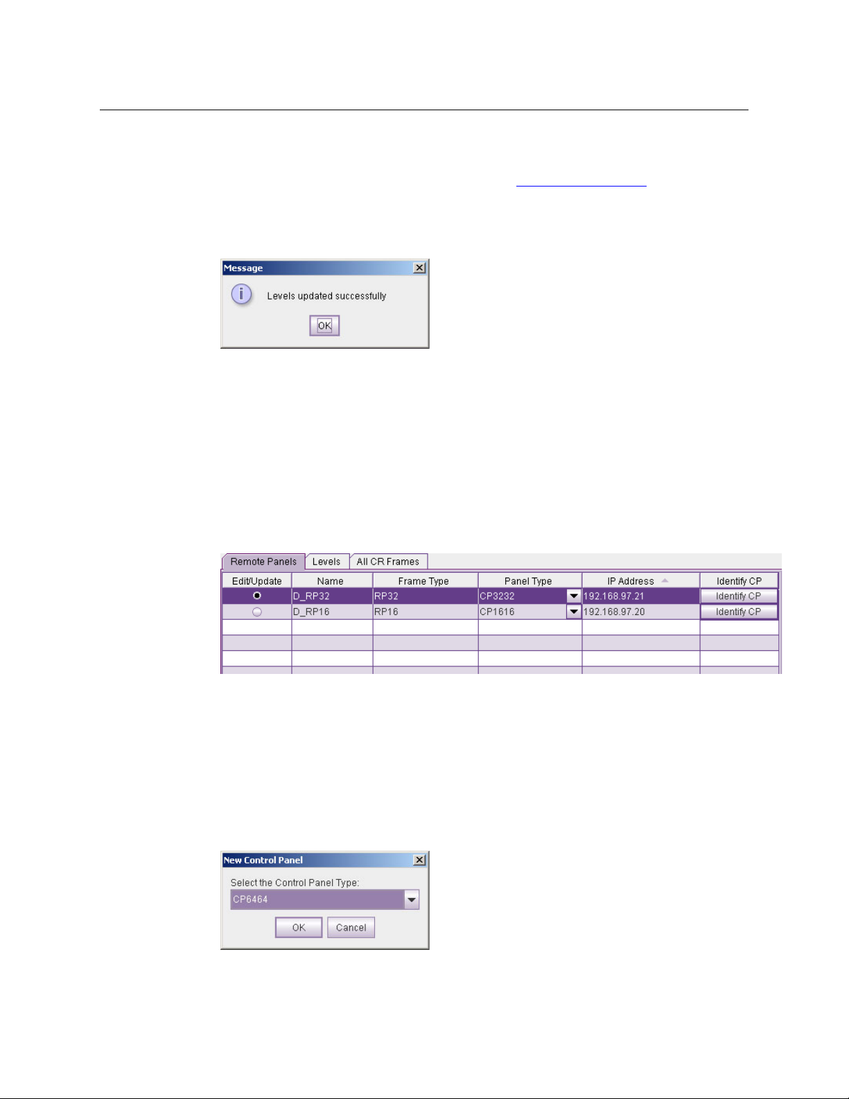
CR6400
User’s Guide
If your subnet has more than one router, CR6400 adds a default level for the router you
chose in the dialog of step 3.
You can now edit the parameters for this level. (See How to Update a Level
5 Repeat steps 2–4 for additional levels.
When you have finished adding levels, click Update Router Levels to send the level configuration data to the routers. You should see a confirmation message:
Note that adding a level creates an additional level for one of the routers that already exists on
the subnet. You cannot create levels that do not correspond to a router.
This is especially useful when you are planning to use an AES router to switch multiple AES
levels.
on page 29.)
Configuring a Panel in CRSC
1 Go to the ‘Remote Panels’ page of CRSC.
2 Select a Remote Panel Module
At the bottom of the page, in the ‘Network Frame Summary’ is a ‘Remote Panels’ tab:
Remote Panels Tab
Click the radio button in the row of the remote panel module that you want to configure.
3 Specify the panel type that is assigned to this remote panel module.
If the panel type is undefined, click in the ‘Panel Type’ field of the selected row. A drop-down
list of panel types appears. Choose a panel type from that list.
If the panel type has already been defined, and you want to change it (and the configuration
assigned to the remote panel module) click the ‘New’ button at the bottom of the page.
In either case, CRSC will present a dialog in which you can choose a panel type:
The panel types that are listed in the dialog depend entirely on what actual panel CRSC
believes is mounted on the remote panel module. (You might need to click the ‘Refresh
31
Page 42

Configuration
Functions 1–32
Functions 33–64
Functions 65–96
Functions 97–128
128 functions128 functions
CRSC Networks
Summary’ button at the bottom of the page to bring CRSC and the actual hardware into
sync.)
Among the various panel types, these are the panel types related to CR6400 routers:
CP32-6464 CP6401 CP6464
You will be able to choose CP32-6464 only if a CP3232 is mounted on the remote panel module (or if no panel is mounted.)
You will be able to choose CP6401 or CP6464 only if a CP6464 is mounted on the remote
panel module.
4 Select a panel mode: (1) standard, (2) enhanced with hold, or (3) enhanced without hold. The
button functions differ subtly depending on the mode. See Remote Panel Modes
on
page 26.
The differences between the modes are difficult to understand until you see the panels
in operation in the different modes. We recommend that you spend some time
experimenting.
5 Select a paging method.
The functions you assign to buttons for the panel configuration depend on the how the button pages will be switched during operation.
You can assign paging functions only to the 10 configurable buttons at the right sideof the
panel.
There are several paging button types:
For the CP32-6464 For the CP6464
Display Page 1 Display Page 1
Display Page 2 Display Page 2
Toggle Page 1 and Page 2 Toggle Page 1 and Page 2
Display Sources
Display Destinations
Toggle Sources/Destinations
(The CP6401 does not have, or need, paging.)
Either panel
— the CP32-6464 or CP6464 — has an array of 64 function buttons at the left
and 12 function buttons at the right. This array of 64 buttons represents 128 functions,
which are divided into 4 segments:
Paging occurs on the array of 64 buttons; the 12 function buttons at the right are not
affected.
32
Page 43

CR6400
User’s Guide
The ‘Display Page 1’ button causes the panel to present
Segments 1 and 3 Functions 1–32 On the top 32 buttons
Functions 65–96 On the bottom 32 buttons
and the ‘Display Page 2’ button causes the panel to present
Segments 2 and 4 Functions 33–64 On the top 32 buttons
Functions 97–128 On the bottom 32 buttons
The ‘Display Sources’ button (CP6464 only) causes the panel to present
Segments 1 and 2 Functions 1–64 On the 64 buttons
and the ‘Display Destinations’ button (CP6464 only) causes the panel to present
Segments 3 and 4 Functions 65–128 On the 64 buttons
The default button mnemonics for the ‘Display Sources’ and ‘Display Destinations’ buttons
are ‘SHOW SRC’ and ‘SHOW DST’.
When you click on any paging button in the configuration page, CRSC changes the graphic
to display the button page represented by the paging button you clicked.
The terms ‘Display Sources’ and ‘Display Destinations’ denote that destination buttons are
not permitted on the page of source buttons and source buttons are not permitted on the
page of destination buttons. (The ‘Display Page 1’ and ‘Display Page 2’ buttons do not have
this restriction.)
If, while you are editing a CP6464, you click ‘Show SRC’ and the source page is visible and
attempt to change a source button to a destination button, CRSC gives an error message:
Level buttons and salvo buttons are permitted anywhere.
(The mnemonics apply only in the ‘Remote Panels’ page. Actual panels requre you to fabricate appropriate clear plastic button legends if their buttons are to have legends.)
6 Define button functions
It can take a certain amount of planning
— away from CRSC and the CR6400 — to know what
you want your panel(s) to do, especially if you have a complex system.
Any configurable button on any remote panel can be configured to perform one of several
functions:
• Defining Destination Buttons
• Defining Level Buttons
• Defining Salvo Buttons
• Defining Source Buttons
Buttons that you do not define remain undefined (called “unused” in the drop-down list for
button types) and remain unlit (dark) when the panel is in use.
33
Page 44

Configuration
CRSC Networks
The buttons in the graphic image of the configuration page correspond in number and position to the buttons of the actual control panel. (The CP6401 is an exception: the graphic has
a button for the configured destination, but the panel has no such button.)
The ‘Destination Lock’ and ‘Panel Lock’ buttons (both red in the panel graphic) are not configurable for any panel.
7 Save the remote panel configuration.
Click ‘Update Panel’ to transfer the remote panel configuration to the selected remote panel
module. (The transfer takes about one minute.)
You can also click ‘Save to File . . . ’ at the bottom of the page to save a copy of the remote
panel configuration to your file system. At any time you can click ‘Read from File . . .’ to
retrieve a saved configuration.
It is a good idea to save all your remote panel configurations in case your remote panel
modules are ever reset to their factory-default state.
Defining Destination Buttons
To configure a button as a destination button:
1 Click on the image of the particular button you want to configure.
2 Choose ‘Destination’ from the ‘Button Function’ drop-down list. The ‘Configure Button’s Out-
puts’ table appears. It has 8 rows. Each row can represent a level/output pair.
34
3 Enter (level, output) pairs on rows of the table. Click on ‘Level’ field to select a level from
drop-down list. Click in the ‘Output’ field to enter an output number manually.
You can use the context menu to edit the destination table.
You can drag-and-drop levels from the ‘Levels’ table to the destination table.
4 Optionally enter a mnemonic in the ‘Device Name / Button Label’ field.
The purpose of the table is to identify the output ports that compose the destination.
The outputs you specify are in the range you specified as the “Controller Outputs” in the ‘Router
Levels’ page. For example, suppose a 32×32 AES router is divided into 4 equal partitions:
Level A = outputs 1–8,
Level B = outputs 9–16,
Level C = outputs 17–24,
Level D = outputs 25–32 where each level’s controller outputs start counting at 1.
Page 45
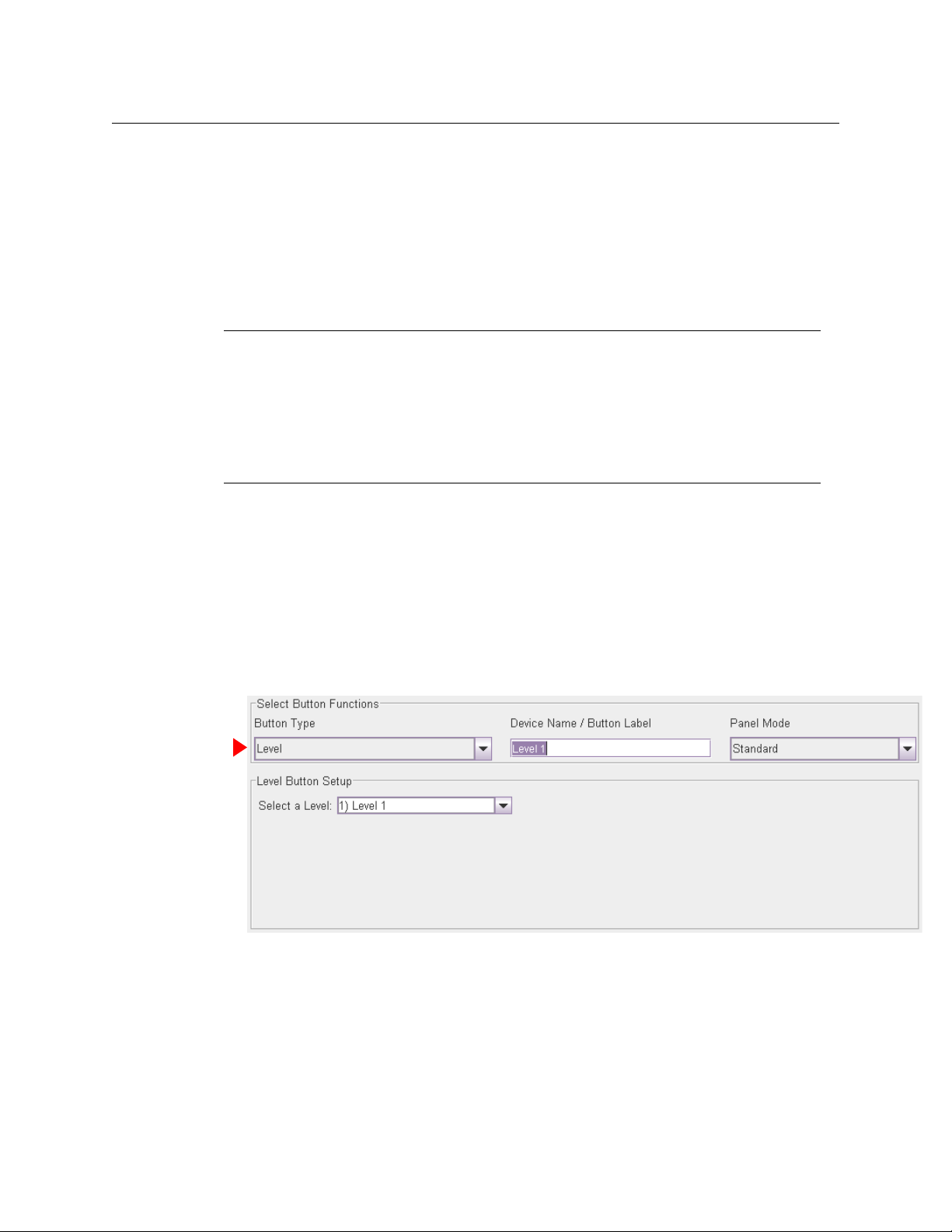
CR6400
User’s Guide
When entering an output on level C, you specify an output in the range 1–8, not 17–24. Output
3 of level C is router output 19 (in this example). You would specify (level C, output 3) in the table
and run cable to the router’s output BNC numbered 19.
Entries in the ‘Level’ column are drop-down lists. The drop-down list shows available levels. The
number of choices in the list diminishes as you add levels to the destination button’s level list.
CR6400 does not allow you to represent the same level more than once.
How you organize levels is up to you. It is recommended that you place, as the first entry in the
list, the level you want to be considered the primary level. Typically this would be a video level.
Special Case:
The CP6401 does not have destination buttons because it is single-destination control
panels. (A “default destination” button does, however, appear in the configuration page for
a CP6401, just to the left of the Destination Lock button.)
To configure the implicit destination of a CP6401, select the button labeled ‘DEF DEST’ and
specify its levels and outputs as you would any ordinary destination.
The default destination does not correspond to any physical button an operator can press.
Defining Level Buttons
A level is a partition within a router. A group of levels the router partitions that can be switched
simultaneously by a take performed at a control panel.
To configure a button as a level button:
1 Click on the image of the particular button you want to configure.
2 Choose ‘Level’ from the ‘Button Function’ drop-down list. The ‘Level Button Setup’ table
appears. It has one field: a drop-down list of defined levels. Select a level from the dropdown list.
3 Optionally enter a mnemonic in the ‘Device Name / Button Label’ field. (Button mnemonics
are used only in the ‘Remote Panels’ page, but they can be helpful.)
A panel requires one level button for every level that is to be controlled at the panel. ‘Takes’ do
not occur on unselected levels. A level cannot be selected unless it is on a button, with one
exception: if a panel has no level buttons defined, ‘takes’ and locks occur on all levels defined for
the destination selected.
35
Page 46
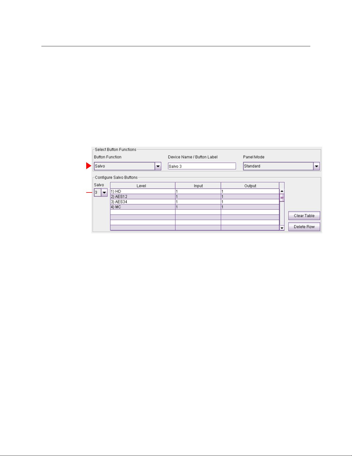
Configuration
Salvo ID
CRSC Networks
Defining Salvo Buttons
A salvo is a stored sequence of primitive takes. A primitive take routes one router input to one
router output, on a designated level (or partition). You can define up to 64 different salvos for a
panel and each salvo can execute up to 64 primitive takes, subject to a total of 1024 primitive
takes. (That could mean, for example, 16 salvos of 64 takes or 64 salvos of 16 takes, or any other
combination.)
To configure a button as a salvo button:
1 Click on the image of the particular button you want to configure.
2 Choose ‘Salvo’ from the ‘Button Function’ drop-down list. The ‘Configure Salvo Buttons’
table appears. It shows the sequence of takes. The salvo (one of 64) is identified by number
at the left.
3 Choose the salvo you want to assign to the salvo button in the ‘Salvo’ drop-down list at the
left. (Salvos are numbered from 1 to 64.)
4 Enter simple take data in each row of the table until you have completed the salvo. (A salvo
can include up to 64 primitive takes.)
A primitive take entry consists of a level specification in the ‘Level’ column, a router input in
the ‘Input’ column and a router output in the ‘Output’ column.
You can drag-and-drop levels from the ‘Levels’ table to the destination table.
You can right-click the salvo table to get a context menu to build a salvo more quickly. The
context menu applies to the column in which you have selected a field. Be careful to select
one or more fields before you right-click a column. See the CRSC User’s Guide for information.
The input and output numbers are “controller” numbers, not physical I/O numbers. Controller numbers are relative to the partition (level) chosen for the take.
A zero value in any of the fields renders the take a no-op.
5 Optionally enter a mnemonic in the ‘Device Name / Button Label’ field.
Salvos execute in the remote panel module. Salvos cannot contain loops. It is indeterminate
what happens when salvos in more than one remote panel module execute simultaneously.
36
Page 47
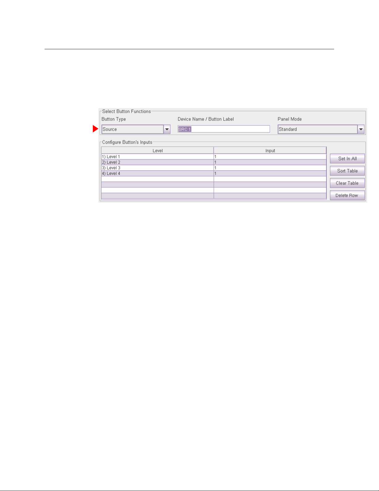
CR6400
User’s Guide
Defining Source Buttons
To configure a button as a source button:
1 Click on the image of the particular button you want to configure.
2 Choose ‘Source’ from the ‘Button Function’ drop-down list. The ‘Configure Button’s Inputs’
table appears. It has 8 rows. Each row can represent a level/input pair.
3 Enter (level, input) pairs on rows of the table. Click on ‘Level’ field to select a level from drop-
down list. Click in the ‘Input’ field to enter an input number manually.
You can use the context menu to edit the destination table.
You can drag-and-drop levels from the ‘Levels’ table to the destination table.
4 Optionally enter a mnemonic in the ‘Device Name / Button Label’ field.
The purpose of the table is to identify the input ports that compose the source.
The inputs you specify are in the range you specified as the “Controller Inputs” in the ‘Router Levels’
page. For example, suppose a 32×32 AES router is divided into 4 equal partitions:
Level A = inputs 1–8,
Level B = inputs 9–16,
Level C = inputs 17–24,
Level D = inputs 25–32 where each level starts counting at output 1.
When entering an input on level C, you specify an input in the range 1–8, not 17–24. Input 3 of
level C is router input 19 (in this example). You would specify (level C, input 3) in the table and
run cable to the router’s input BNC numbered 19.
Entries in the ‘Level’ column are drop-down lists and list available levels. The number of choices
diminishes as you add levels to the source button’s level list. CR6400 does not allow you to
represent the same level more than once.
How you organize levels is up to you. It is recommended that you place, as the first entry in the
list, the level you want to be considered the primary level. Typically this would be a video level.
Unused Button Type
A fifth entry appears in the ‘Button Type’ drop-down list — unused. Buttons that you designate
“unused” perform no function (and remain unlit on the panel).
37
Page 48

Configuration
NV9000 Networks
Shortcuts
There are several shortcuts in CRSC’s ‘Remote Panels’ page that make configuring remote panels
quick and easy. Please refer to the CRSC User’s Guide.
NV9000 Networks
Routers
For CR Series routers, you must specify an IP address, in CRSC, that is appropriate for use in the
NV9000 control system. Subsequently you will define an entry for that router, in NV9000-SE Utilities, that has that same IP address and that uses ‘NV Compact Router’ protocol. You will also
specify, in NV9000-SE Utilities, the router’s physical level(s), in much the same way as you would
in CRSC.
In NV9000-SE Utilities, router I/Os must be defined (and grouped into “devices”). Considering all
the routers in the entire NV9000 system, this is a fairly complex task. Defining router I/Os in
NV9000-SE Utilities is different from defining router I/Os in CRSC.
After specifying the router’s IP address, you must connect it into the NV9000 system’s Ethernet
network. This might require removing the router from the subnet on which you used it in CRSC.
Panels
If CR Series control panels are to be used in an NV9000 system, you must set up, in CRSC, one or
more remote panel modules for NV9000 operation. (Do this in the ‘NV9000 Remote Panel
Settings’ page. Please refer to the CRSC User’s Guide for details.)
There is an option in the ‘NV9000 Remote Panel Settings’ page not to use DHCP for panel
discovery, instead giving the panel a static IP address. (That is not recommended because DHCP
is NV9000-SE Utilities’ normal method of identifying panels.)
In NV9000-SE Utilities, create panel configurations for your remote panel modules, specifying
either NVRP16 or NVRP32 as the panel type. Your remote panels are then configurable
according to the methods and constructs of NV9000-SE Utilities. The configurations of remote
panels created in NV9000-SE Utilities have only a slight resemblance to panels configured in
CRSC.
In NV9000-SE Utilities, all panels require unique panel IDs. Be careful about defining panel IDs.
When you create, or change, a panel configuration, eventually you will write the entire NV9000
configuration to the system controller. You can use the ‘Dynamic Update’ button in NV9000-SE
Utilities to save time if all you have to update are panel changes.
How to Convert a Remote Panel Module
1 Go to the ‘NV9000 Remote Panel Settings’ page.
2 In the ‘Remote Panel’ tab, click the radio button on the row listing the remote panel module
you want to convert.
3Either check the ‘Enable NV9000 Mode’ check box to convert the remote panel module.
Or uncheck the ‘Enable NV9000 Mode’ check box to revert the remote panel module to use
in a CRSC network.
38
Page 49

CR6400
User’s Guide
4 If you have enabled NV9000 mode, enter a panel ID in the ‘NV9000 Panel ID’ field.
The panel ID must be a number unique within the NV9000 configuration. It must contain no
special characters, spaces, or punctuation marks.
By default, the panel ID is composed of the last two octets of the module’s current IP
address. For example, if its IP address is 192.168.97.21, then the default panel ID is 97021.
5 If you have enabled NV9000 mode, check the ‘Use DHCP to acquire IP Address’ check box if
you want the NV9000 system to use DHCP to determine the remote panel module’s IP
address. Otherwise, the panel’s IP address will be fixed in the NV9000 system and will retain
its present IP address.
Using DHCP is strongly recommended.
6Click Update Remote Panel to complete the conversion.
39
Page 50

Configuration
NV9000 Networks
40
Page 51

Summary
Stand-Alone Operation
Chapter 5 provides operating instructions for the CR6400 routers and the CP6464 control panel
in a stand-alone system.
Topics
Summary . . . . . . . . . . . . . . . . . . . . . . . . . . . . . . . . . . . . . . . . . . . . . . . . . . . . . . . . . . . . . . . . . . . . . . . . . . . . . . . . 41
Stand-Alone Router
Stand-Alone Network
There are 3 ways to use the CR6400 routers and the CP6464:
• A single stand-alone CR6400 router with a “captive” CP6464 control panel.
• A network of stand-alone CR6400 routers with a captive panel (or panels).
• In a CRSC network of mixed router and panel types (with remote panel modules).
This section is about stand-alone operation. Please refer to Chapter 6, CRSC Network Operation
on page 49, for information about using CRSC networks.
. . . . . . . . . . . . . . . . . . . . . . . . . . . . . . . . . . . . . . . . . . . . . . . . . . . . . . . . . . . . . . . . . . . . . . . 42
. . . . . . . . . . . . . . . . . . . . . . . . . . . . . . . . . . . . . . . . . . . . . . . . . . . . . . . . . . . . . . . . . . . . . 45
,
Te rm i no l og y
It is essential for understanding the material that follows to define the terms “source” and
“des ti na tion.”
In general, the terms source and destination refer to devices (e.g., VTRs, cameras, monitors) that
can be connected to the I/O cards of the router. However, in discussions of routers, we usually
think of sources and destinations only as the connectors to which a device is connected and we
ignore the devices. (In fact, the router functions properly even when it is not actually connected
to any devices.)
A port is a single connector (DIN 1.0/2.3) on a router.
An input port, or just input, is a port that receives a signal.
An output port, or just output, is a port that sends a signal.
For a Single Stand-Alone Router
1A source is a one input at the rear of the CR6400 router.
2A destination is one output at the rear of the CR6400 router.
A CR6400 router has a 64×64 switching matrix and thus supports up to 64 inputs and 64
outputs.
41
Page 52

Stand-Alone Operation
Stand-Alone Router
For a Stand-Alone Router Network
1A destination is set of N outputs on the CR6400s in the network, where N is the number of
routers. A destination uses the same output on all N routers.
For example, destination 55 comprises output 55 on router 1, output 55 on router 2, output
55 on router 3, and output 55 on router 4. (All available levels are included in the destination)
2A source is set of N inputs on the routers in the network, where N is the number of routers. A
source uses the same input on all N routers.
For example, source 12 comprises input 12 on router 1, input 12 on router 2, input 12 on
router 3, and input 12 on router 4. (All available levels are included in the source.)
3 If the operator routes source J to destination K, then input J is taken to output K on all
enabled levels. (A level — i.e., a router — is enabled when a level button selects it.)
Breakaway can occur when you choose different levels for separate takes to the same destination. (Breakaway is an undefined concept for a single router.)
A CR6400 network supports up to 64 sources, each of which can comprise up to 4 inputs, and
supports 64 destinations, each of which can comprise up to 4 outputs.
Stand-Alone Router
A “stand-alone” router is one operated independently with an attached CP6464 control panel.
(Automation is possible, but this document does not address automation.)
Startup
To power up a router, connect the 4-pin connector the power supply to PS1 or PS2. Then plug
the power supply into AC power outlet. If you have chosen to use two power supplies for redundancy, connect one to PS1 and the other to PS2.
At power-up, the router loads stored program code into its internal FPGA and restores its
previous operational state. (The “state” includes the crosspoint map between inputs and
outputs and which of the outputs are locked.)
If a router’s rotary switch is set to the 0 position, the router reverts to the factory-default
state, not its previous state.
At power-up, the router detects the presence or absence of a video reference signal.
At power-up, a control panel’s ‘Panel Lock’ button is on (red). You must turn Panel Lock off
before you can use the panel.
At power-up, a control panel lights one of its level buttons, if the rotary switch of the router on
which it is mounted is set to a value in the range 1–4. If the rotary switch is set otherwise, the
control panel does not light any level button.
For a single stand-alone CR6400, level selection is disabled, although a level button might be
illuminated.
42
Page 53

CR6400
49 50 51 52 53 54 55
33 34 35 36 37 38 39
17 18 19 20 21 22 23
1234567
MON
1
PNL
LOCK
DST
LOCK
DST
MODE
SRC
MODE
Destination Mode
49 50 51 52 53 54 55
33 34 35 36 37 38 39
17 18 19 20 21
22
23
1234567
VTR
2
PNL
LOCK
DST
LOCK
DST
MODE
SRC
MODE
Source Mode
User’s Guide
Takes
There are 4 very simple steps to perform a take (using a CP6464 panel):
1 Press the destination mode button. (The selection buttons turn amber, representing desti-
nations.)
2 Press one of the 64 selection buttons to select a destination. The destination’s button goes
high-tally. It will be red if the destination is locked and the take will not be allowed.)
3 Press the source mode button. (The selection buttons turn green, representing sources.)
4 Press one of the 64 selection buttons to select a source. The source’s button goes high-tally.
The take is complete.
Example
You want to route input 4 (VTR2) to output 5 (MON1). The monitor is presently connected to
input 3 (VTR1).
1 Press the ‘Destination Mode’ button. The selection buttons turn amber. Then press selection
button 5. It is labeled ‘MON1’ in this example. It goes high tally:
2 Press the ‘Source Mode’ button. The selection buttons turn green. Then press selection but-
ton 4. The button for input 3 goes low tally and selection button 4 (VTR2) goes high-tally.
VTR
1
3 The take is complete.
The panel remains in source mode until you again press ‘Destination Mode’. If you forget the
destination to which you made the route, the destination will be high-tally when you press
‘Destination Mode’.
If a destination is locked, it will be low-tally red. If you press its button, it will go high-tally
red. The panel remains in destination mode. You cannot perform a take for a destination that
is locked. See Locks
.
43
Page 54

Stand-Alone Operation
PNL
LOCK
DST
LOCK
DST
MODE
SRC
MODE
Panel LockDestination Lock
64
48
32
16
PLDL
49 50 51 52 53 54 55
33 34 35 36 37 38 39
17 18 19 20 21 22 23
1234567
MON
1
PNL
LOCK
DST
LOCK
DST
MODE
SRC
MODE
1. Destination Mode
3. Destination Lock2. Destination
Stand-Alone Router
Locks
The CP6464 has 12 function buttons. Two of the function buttons are locks:
Panel Lock
Pressing ‘Panel Lock’ disables the control panel. Only the Panel Lock button remains enabled.
Pressing it again re-enables the control panel.
When the control panel is locked, the lock button is bright red and the state of the entire control
panel is protected. Changes from the control panel are disabled. The panel lock button is low
tally green when the control panel is not locked.
Destination Lock
Destination lock prevents selecting another source for the currently selected destination. To
lock a destination,
1 Press the ‘Destination Mode’ button.
2 press the desired selection button.
3 Press ‘Destination Lock’.
This sample shows destination 5 locked:
(Press ‘Source Mode’ to see the source that feeds the destination. The button for that source is
high-tally.)
If you subsequently press a button for a destination that is locked, the button goes high tally
(red), and the Destination Lock button goes high tally, as this example shows.
Other destinations remain unchanged, whether locked or unlocked, and specifically, you can
route the source that feeds a locked destination to any number of other destinations.
44
Page 55
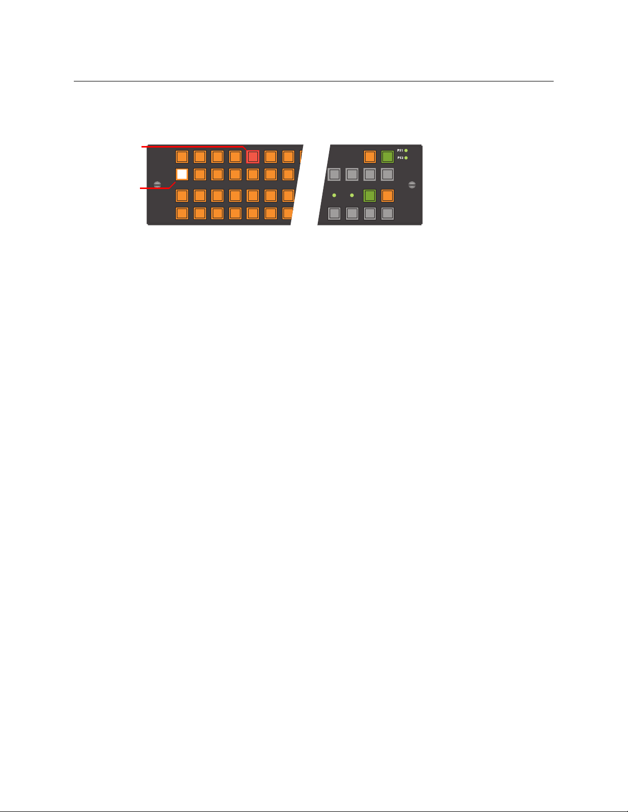
When you select another (unlocked) destination, a locked destination goes low-tally red. This
49 50 51 52 53 54 55
33 34 35 36 37 38 39
17 18 19 20 21 22 23
1234567
PNL
LOCK
DST
LOCK
DST
MODE
SRC
MODE
Locke d
Destination
Selected
Destination
illustration shows destination 1 selected and destination 5 locked. Because the selected destination is not locked, the ‘Destination Lock’ button is not red, but low-tally amber.
To unlock a destination, press the selection button for the destination and then press Destination Lock (again). The selection button for the destination reverts to amber and the ‘Destination
Lock’ button goes low-tally amber.
Stand-Alone Network
A stand-alone network includes 1–4 CR6400 routers, one CP6464 panel, and an Ethernet switch.
(Automation is possible, but this document does not address automation.)
CR6400
User’s Guide
Startup
To power up a router or a remote panel module, connect the 4-pin connector the power supply
to PS1 or PS2. Then plug the power supply into AC power outlet. If you have chosen to use two
power supplies for redundancy, connect one to PS1 and the other to PS2.
At power-up, a router loads stored program code into its internal FPGA and restores its previous
operational state. (The “state” includes the crosspoint map between inputs and outputs and
which of the outputs are locked.)
At power-up, a router detects the presence or absence of a video reference signal.
At power-up, routers “discover” the presence and state of other routers in the network.
At power-up, a control panel’s ‘Panel Lock’ button is on (red). You must turn ‘Panel Lock’ off
before you can use the panel.
There must be from 1 to 4 routers whose levels are distinct and in the range 1–4. The level
buttons on the panel that correspond to the levels of the routers are illuminated and operable.
If the levels are not distinct, your network will not perform correctly.
Level Selection
A video or audio device typically receives or transmits signals of several types. A VTR might
handle HD, SD, AES, and machine control signals that need to be switched simultaneously. The
different signal types are considered “levels” in a router network.
In a stand-alone CR6400 network, multiple levels can be taken to a destination simultaneously
(in a single button press).
In a stand-alone CR6400 network, multiple levels of a destination can be locked simultaneously
(again, in a single button press).
45
Page 56
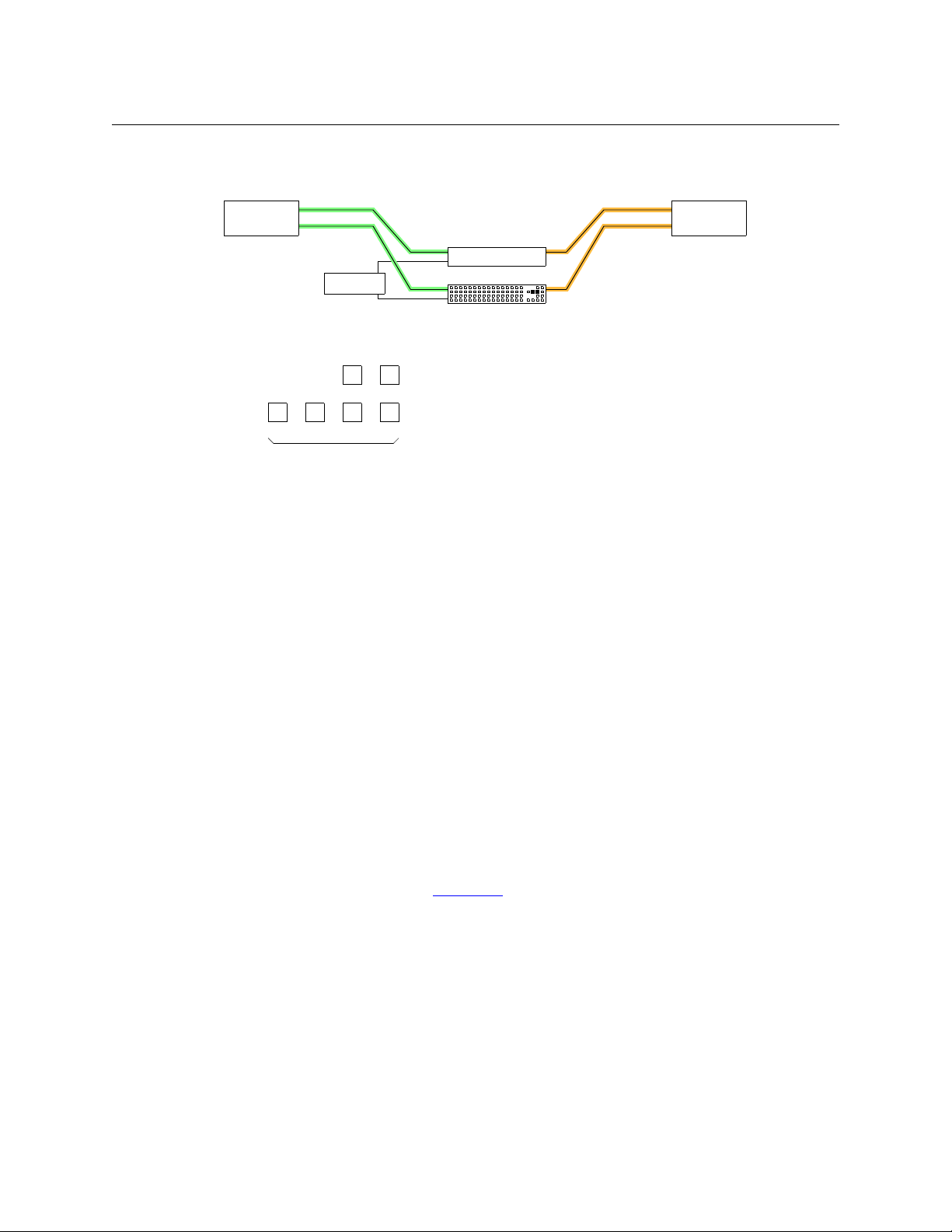
Stand-Alone Operation
VTR
AES
MON
HD
AES
HD
1
2
(AES Router + Panel)
3Gig Router
Ethernet
(Destination Lock) (Panel Lock)
Levels
1234
Stand-Alone Network
Example
Two levels, HD and AES, are taken from the VTR to the monitor:
The four level buttons on a control panel correspond to the four router levels, with level 1 on the
left and level 4 on the right.
A level button is illuminated (in amber) if a router at that level is present in the network. The
button is dark if not.
A level button is high-tally when the level is selected and low-tally when not.
If the rotary switch setting of a router is not in the range [1–4] then its level cannot be
controlled by the level buttons.
Exceptions
In most cases, the level buttons are toggles: press the level button to select the level, press the
button again to deselect the level. However, there is an exception: when you have selected all
the levels in your network, pressing any level button deselects the other levels and leaves the
one you pressed selected.
Another exception is when you have only one router in your network. Pressing the level selection button has no effect. The single router is always selected.
Takes
A network of routers is capable of multi-level takes.
Follow these steps to perform a multi-level take:
1 Press the level buttons on a panel to select the levels for the take. Be aware of the level selec-
tion exceptions, listed under Exceptions
2 Press ‘Destination Mode’.
3 Select a destination.
4 Press ‘Source Mode’.
5 Select a source.
The take is complete. A routing switch occurs on each level you selected at the remote panel
module.
above. The buttons for selected levels are high-tally.
46
Page 57

CR6400
PNL
LOCK
DST
LOCK
DST
MODE
SRC
MODE
LVL
4
LVL
3
LVL
2
LVL
1
Level selection buttons
Panel LockDestination Lock
64
48
32
16
PLDL
User’s Guide
Locks
Performing locks in a network is almost the same as performing locks for a stand-alone CR6400.
However, please note:
• Pressing ‘Panel Lock’ locks that panel and no other.
• A destination lock locks a destination on all selected levels. The lock state of a destination is
not changed on unselected levels.
If all the selected levels of a destination are locked, the destination button is red. If some of
the selected levels of a destination are unlocked, the destination button is amber.
• A destination locked at one control panel cannot be unlocked at another control panel.
Be sure to unlock any locks before removing a panel from a network!
• Locks can be released using CRSC.
As previously stated, two of the function buttons are locks and four are level buttons. Two others
are destination mode and source mode.
This illustration shows a system that has 3 levels (1–3), two of which are selected. Buttons for
selected levels are high-tally. The button for (non-existent) level 4 is dark.
Panel Lock
Pressing ‘Panel Lock’ disables the control panel on which you press ‘Panel Lock’. Only the ‘Panel
Lock’ button remains enabled. Pressing it again re-enables the control panel.
When the control panel is locked, the Panel Lock button is bright red and the state of the entire
control panel is protected. Changes from the control panel are disabled. The ‘Panel Lock’ button
is low tally green when the control panel is not locked.
Remember that a ‘Panel Lock’ button locks that panel only. It does not lock any router, other
control panels, or the network.
Destination Lock
Destination lock prevents an operator from selecting another source for the currently selected
destination. In a network, sources and destinations comprise one or more levels. When you lock
a destination, it is locked on the levels you select. And when you unlock a destination, it is
unlocked on the levels you select.
47
Page 58

Stand-Alone Operation
49 50 51 52 53 54 55
33 34 35 36 37 38 39
17 18 19 20 21 22 23
1234567
PNL
LOCK
DST
LOCK
LVL
3
LVL
2
LVL
1
DST
MODE
SRC
MODE
Locked
Destination
Destination Lock
49 50 51 52 53 54 55
33 34 35 36 37 38 39
17 18 19 20 21 22 23
1234567
PNL
LOCK
DST
LOCK
LVL
3
LVL
2
LVL
1
DST
MODE
SRC
MODE
Locke d
Destination
Selected
Destination
Stand-Alone Network
To unlock the destination completely, you must select exactly the levels on which it was
locked. But, after you lock a destination on levels, it is difficult to remember on which levels
you have locked it.
To lock a destination,
1 Press level buttons on a panel to select the intended levels.
The following illustrations show a system that has 3 levels (1–3), two of which are selected.
Buttons for selected levels are high-tally.
2 Press ‘Destination Mode’.
3 Press the selection button for the destination you want to lock.
4 Press ‘Destination Lock’.
This sample shows destination 5 locked on levels 2 and 3, but not level 1:
When you press ‘Destination Lock’, immediately goes high-tally red and the selection button for
the destination goes high tally red. Changes to that destination are disabled on all selected
levels. If you subsequently press a destination button that is locked, the button goes high tally
(red), and the Destination Lock button goes high tally, as this sample shows.
Changes to other destinations remain enabled and other destinations remain unchanged,
whether locked or unlocked. Note that you can route the source that feeds a locked destination
to any number of other destinations.
When you select another (unlocked) destination, a locked destination goes low-tally red. This
illustration shows destination 1 selected and destination 5 locked. Because the selected destination is not locked, the ‘Destination Lock’ button is not red, but low-tally amber:
To unlock a destination,
1 Press level buttons on a panel to select the intended levels.
2 Press ‘Destination Mode’.
3 Press the selection button for the destination you want to unlock.
4 Press ‘Destination Lock’.
This will (1) clear the lock on the locked levels you have selected and (2) set the lock on
unlocked levels you have selected.
48
Page 59

Summary
CRSC Network Operation
Chapter 6 provides operating instructions for control panels under a CRSC network (a network
of routers and remote panels of mixed type).
Topics
Summary . . . . . . . . . . . . . . . . . . . . . . . . . . . . . . . . . . . . . . . . . . . . . . . . . . . . . . . . . . . . . . . . . . . . . . . . . . . . . . . . 49
Control Panel Buttons
Power Up and Reset
Performing Takes
Performing Locks
Executing Salvos
Performing Level Selection
A CRSC network can include a mix of different CR Series routers, panels, and remote panel
modules, in which the routers and remote panel modules have been configured in CRSC.
Among the devices in a CRSC network can be CR6400 family routers and CP6464 panels. In addition, a CRSC network can include two artificial panel types — the CP32-6464 and CP6401 —
panels that can control the 64×64 matrices of CR6400 routers.
The CP32-6464 “type” is really just a configuration option for an actual CP3232; similarly, the
CP6401 “type” is just a configuration option for an actual CP6464.
Although a CRSC network can contain many panel types, we focus here on those 3 panels: the
CP32-6464, CP6401, and CP6464. These panels are the ones that can control CR6400 routers.
Please refer to the CRSC User’s Guide for information regarding other routers and panels.
. . . . . . . . . . . . . . . . . . . . . . . . . . . . . . . . . . . . . . . . . . . . . . . . . . . . . . . . . . . . . . . . . . . . 50
. . . . . . . . . . . . . . . . . . . . . . . . . . . . . . . . . . . . . . . . . . . . . . . . . . . . . . . . . . . . . . . . . . . . . . 55
. . . . . . . . . . . . . . . . . . . . . . . . . . . . . . . . . . . . . . . . . . . . . . . . . . . . . . . . . . . . . . . . . . . . . . . . . 59
. . . . . . . . . . . . . . . . . . . . . . . . . . . . . . . . . . . . . . . . . . . . . . . . . . . . . . . . . . . . . . . . . . . . . . . . . 68
. . . . . . . . . . . . . . . . . . . . . . . . . . . . . . . . . . . . . . . . . . . . . . . . . . . . . . . . . . . . . . . . . . . . . . . . . 70
. . . . . . . . . . . . . . . . . . . . . . . . . . . . . . . . . . . . . . . . . . . . . . . . . . . . . . . . . . . . . . . . 70
Te rm i no l og y
Please be aware that the definitions applicable to CRSC network operation often differ from
those applicable to stand-alone networks.
It is essential for the material that follows to define the terms “source” and “destination.”
In general, the terms source and destination refer to devices (e.g., VTRs, cameras, monitors) that
can be connected to the I/O cards of the router. However, in discussions of routers, we usually
think of sources and destinations only as the connectors to which a device is connected and we
ignore the devices. (In fact, the router functions properly regardless of whether it is actually
connected to any real devices.)
A port is a single I/O connection on a router.
An input port, or just input, is one that receives a signal.
An output port, or just output, is one that sends a signal.
49
Page 60

CRSC Network Operation
Control Panel Buttons
A source is a set of inputs from among all the inputs of all the routers in the network. In a CRSC
network, there is no constraint on which inputs may compose the source.
A destination is a set of outputs from among all the outputs of all the routers in the network. In
a CRSC network, there is no constraint on which outputs may compose the destination.
(The inputs belonging to a source are presumably related and connected to a source device,
such as a camera. The outputs belonging to a destination are presumably related and
connected to a destination device, such as a monitor.
The inputs of sources and the outputs of destinations collectively form levels. For example, a
VTR might send and receive HD, AES, and analog audio. Three routers could carry these three
signal types, each router itself being considered a level.
A router could also be divided into two partitions, each half the size of the router. That way the
router could carry two levels.
Levels in CRSC are numbered. Level numbers must be in the range [1–250]. A CRSC network
supports up to 8 defined levels in total. Each router may be partitioned into a maximum of 4
levels, subject to the limit of 8 levels for the network.
It is important for persons operating control panels to understand these concepts.
Panel Operation
Operating a control panel is usually quite simple, but can also be quite confusing if you do not
understand the way the panels work in their particular modes. The basic operations are the
same for all panels with some minor exceptions:
• The CP3201 and CP6401 are slightly different because they are single-destination panels
having “default” destinations.
• The panels that can control the 64×64 matrices of CR6400 routers (the CP32-6464, CP6401,
and CP6464) are different from others because they can have “paging” buttons.
This chapter briefly describes how to use the control panel to perform the following tasks:
• Perform ‘takes’ (normal and breakaway). See Performing Takes on page 59.
• Lock or unlock destination or control panels. See Performing Locks on page 68.
• Execute salvos. See Executing Salvos on page 70.
• Select levels. See Performing Level Selection on page 70.
Although operations are usually straightforward, the meaning of the operations differ according
to panel mode. See Remote Panel Operating Modes
Before using a panel, it is recommended that you become familiar with how its buttons are
grouped and what different button illuminations denote, as described in Control Panel Buttons
following.
Control Panel Buttons
on page 112.
,
50
Most CR Series control panels were designed before the existence of CRSC. Their button layouts
(and button colors) are appropriate to what has been called “default” mode (and what this
document calls “stand-alone” mode) where green buttons are grouped together and labeled
“Source” and amber buttons are grouped together and labeled “Dest.” The fixed coloring of the
early panels has little meaning in a CRSC network.
Page 61

CR6400
Panel LockDestination Lock
49 50 51 52 53 54 55 56 57 58 59 60 61 62 63 64
33 34 35 36 37 38 39 40 41 42 43 44 45 46 47 48
17 18 19 20 21 22 23 24 25 26 27 28 29 30 31 32
12345678910 11 12 13 1415 16
Panel LockDestination Lock
49 50 51 52 53 54 55 56 57 58 59 60 61 62 63 64
33 34 35 36 37 38 39 40 41 42 43 44 45 46 47 48
17 18 19 20 21 22 23 24 25 26 27 28 29 30 31 32
12345678910 11 12 13 1415 16
Source
Dest
Panel LockDestination Lock
User’s Guide
On these early panels, the labels “Source” and “Dest” at the left have no meaning. Operators
must ignore these colors and these labels.
The newer CP6464, a 64×64 panel, does not suffer from the fixed coloring of the earlier panels.
Any button can be green or amber (or red), depending on its function. For the CP6464, source
buttons are in fact green and destination buttons are in fact amber, regardless of their position
on the panel.
The color red indicates one of several conditions. See Red Buttons
, following. A button that is
unlit is either (1) undefined or (2) momentarily turned off.
Figures 6-1, 6-2, and 6-3 show the CP6464, CP6401, and CP32-6464 respectively:
Fig. 6-1: CP6464
Fig. 6-2: CP6401
Fig. 6-3: CP32-6464
There are two fixed-function buttons on all control panels at the top right, as shown in Figures 61, 6-2, and 6-3. The two fixed-function buttons are locks:
• Panel Lock (the rightmost button). Prevents accidental changes on the entire panel.
• Destination Lock. A locked destination is one to which a source may not be routed. This pre-
vents the route(s) to the destination from being changed. When the lock is released, the destination’s content can be changed.
51
Page 62

CRSC Network Operation
Control Panel Buttons
Button Types
For most panels, all buttons except the lock buttons are configurable as:
• Level selection buttons.
• Source buttons.
• Destination buttons.
• Salvo buttons.
The panels that can control the 64×64 matrices of CR6400 routers (CP32-6464, CP6401, and
CP6464) also have what are called paging buttons — buttons that control (1) whether sources or
destinations are presented on the panel or (2) which set of sources and destinations is
presented.
The CP6401 does not have destination buttons. They are single-destination panels.
Panel Modes
Panel modes are applicable to all panels (except the CQX panel). Panels can be configured in one
of 3 modes:
• Standard
• Enhanced, with hold
• Enhanced, without hold
These modes control level selection in quite different ways. Operators will need to know how
levels are managed in the panels they use.
Standard Mode
In standard mode, takes are performed on (manually) selected levels only.
Level selection is persistent and at the discretion of the panel operator. Once the operator
makes a level selection, it remains until the operator changes the selection. The current level
selection enables some sources and destinations and disables others. The sources and destinations that are enabled depend on which level button has precedence. See Button Order
following, for information about precedence.
If no levels are selected, no sources or destinations are enabled. A take cannot occur.
If the panel has no level buttons, all of a destinations’ levels are always selected and all destinations are enabled.
Which level button has precedence depends on the order of level buttons on the panel and the
order in which the operator presses the level buttons. See Button Order
Standard mode allows breakaway. A breakaway is when you route to some, not all, of a destination’s levels. By default, all valid levels are automatically selected when you set up a take. By
creating a breakaway, you route only to the levels you have individually selected.
, following.
,
Enhanced Mode (Hold and No-hold)
‘Takes’ are performed on all the levels specified by the destination.
In enhanced mode, level selection is applicable only to breakaway. Level selection governs the
selection of sources for the breakaway. All sources and destinations are always enabled.
52
Page 63

CR6400
1
17
33
49
2
18
34
50
3
19
35
51
4
20
36
52
5
21
37
53
6
22
38
54
7
23
39
55
8
24
40
56
9
25
41
57
10
26
42
58
11
27
43
59
12
28
44
60
13
29
45
61
14
30
46
62
15
31
47
63
16
32
48
64
(65)
69
(73)
77
(66)
70
(74)
78
67
71
75
79
68
72
76
80
User’s Guide
Enhanced mode has 2 submodes:
• Hold mode — the level selection persists after the destination button is pressed (initiating a
take) and continues indefintely until the operator changes it. This allows an operator to try
different sources. To clear a breakaway, the operator starts a new normal take (non-breakaway) to that destination. See Normal Takes
on page 59.
• No-hold mode — a level selection reverts to the levels defined by the destination after the
operator presses a source button (completing a take). To clear a breakaway, either start a
new normal take to that destination or press a source without a level selection. See Normal
Tak es on page 59.
The choice between hold mode and no-hold mode is meant to accommodate operator or
administrator preferences.
Red Buttons
Depending on context, red means:
• Lock. (The panel is locked or a destination is locked.
• Breakaway. (Applicable to all panels except the CQX panel.)
• Occasionally, red can also indicate an unintentional breakaway that occurs as result of an
improper configuration.
Button Order
The order in which buttons appear on a control panel affects the meaning of level buttons.
Buttons other than level buttons are not affected by button order.
Spatial Ordering
(This means the organization of the buttons on the panel.)
Buttons on a control panel are numbered from left to right, and then from top to bottom. This is
the ordering for the 2RU panels:
(Some button numbers do not correspond to an actual button.)
The button order affects the meaning of level buttons in standard mode: level buttons with
lower numbers have precedence over level buttons with higher numbers.
In standard mode, precedence governs which sources and destinations are enabled for selection
when level buttons are pressed.
Briefly stated, on any button row, level buttons to the left have higher precedence than buttons
to the right. All buttons on an upper row have higher precedence than any button on rows
below that row.
See Performing Level Selection
on page 70.
53
Page 64
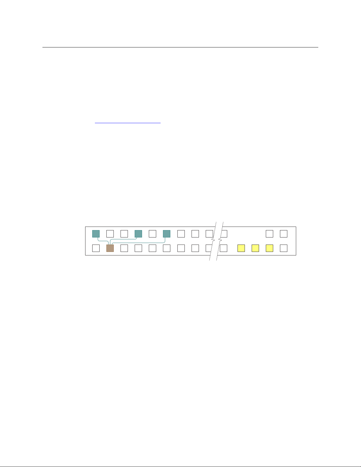
CRSC Network Operation
21 345678916
ABCD
ABC
A
B
C
Control Panel Buttons
Temporal Ordering
(This means the order in which you press buttons.)
In standard mode, the order in which you press level buttons affects the outcome of your operation. However, after a level selection, the order in which the buttons were pressed is no longer
evident. Any set of selected levels can therefore represent a number of different sets of sources
and destinations.
(In enhanced mode, the button pressing order is irrelevant.)
See Performing Level Selection
Button Illumination
Button illumination is applicable to all panels. To discuss button lighting, there are some terms
that are helpful when discussing button states:
Current destination The destination that is currently selected.
Routed source A source that matches or partially matches what is routed to the
Primary level The first configured level for the destination button.
Primary source The routed source on the primary level.
on page 70.
current destination.
Figure 6-4 illustrates the terms:
Fig. 6-4: Buttons on a Panel
In this illustration, blue buttons are routed sources. The brown button is the current destination.
Yellow buttons are selected levels. Buttons without any specific color are unselected.
In this example, the destination uses levels A, B, and C. Level A is the primary level because it is
the first. Source 1 is the primary source because it routes level A (indicated by the letter A over
the source button).
(The example uses blue, brown, and yellow buttons for the purpose of discussion. Real control
panels have green, amber, and red buttons.)
Source Button Colors
In a normal (non-breakaway) take, the (single) source button selected is always high-tally green
(or possibly amber, on a CP32-6464).
In a breakaway in enhanced mode, the primary source is high-tally green (or possibly amber, on
a CP32-6464). Non-primary sources taken are high-tally red.
In a breakaway in standard mode, all taken sources are high-tally green (or possibly amber, on a
CP32-6464).
54
Page 65

CR6400
User’s Guide
Destination Button Colors
The current destination is high-tally amber (or possibly green, on a CP32-6464). All other destinations are unselected and low-tally.
However, if the destination on a button is locked, the button is red, high-tally if selected, and
low-tally if not.
Level Button Illumination
Enhanced Mode
• A level button is high-tally (green or amber) if it is selected and represents the primary level.
• A level button is low-tally (green or amber) if it is not selected and represents the primary
level.
• A level button will be red (in a breakaway only) if it does not represent the primary level. If
the level button is selected, it is high-tally. Otherwise it is low-tally.
• A level button is off if the current destination does not include this level.
Standard Mode
• A level button is high-tally (green or amber) if the level is selected.
• A level button is low-tally (green or amber) if the level is not selected.
Power Up and Reset
Operators generally do not need to bother about startup — unless there is a power outage.
At power-up, and at every reset, a control panel’s ‘Panel Lock’ button is on and red. An operator
must turn the panel lock off before the panel can be used. At power-up, a remote panel
(module) “discovers” the state of the routers in the network and illuminates its buttons to reflect
the routes and levels that were selected prior to power-up (reset). It can take up to 60 seconds to
finish the discovery. The operator can actually start using the panel before the discovery
completes.
Routers at Power-Up
At power-up, a router loads stored program code into its internal FPGA and restores its previous
operational state. (Its “state” includes the name, crosspoint map, levels, and which of the outputs are locked.)
If a router’s rotary switch is set to the 0 position, the router reverts to the factory default
state, not its previous state. Its entire state and all configuration data are lost and will
need to be reconfigured.
At power-up, the router detects the presence or absence of a video reference signal.
55
Page 66

CRSC Network Operation
Functions 1–32
Functions 33–64
Functions 65–96
Functions 97–128
128 functions128 functions
Choosing a Button Page
Remote Panel Modules at Power-Up
At power-up, a remote panel module also loads stored program code into its internal FPGA and
restores its previous operational state. (Its “state” includes all the button definitions and its own
panel mode.)
If a remote panel module’s rotary switch is set to the 0 position, the remote panel
module reverts to the factory default state, not its previous state. Its entire state and all
configuration data are lost and will need to be reconfigured.
Choosing a Button Page
To operate a CP6464 or CP32-6464 control, it is essential to know how to switch between button
pages. These two panel provide several different “paging” buttons:
For the CP32-6464 For the CP6464
Display Page 1 Display Page 1
Display Page 2 Display Page 2
Toggle Page 1 and Page 2 Toggle Page 1 and Page 2
Display Sources
Display Destinations
Toggle Sources/Destinations
(The CP6401 does not have, or need, paging.)
The buttons of your control panel might or might not have button legends or button
graphics. The legends or graphics might or might not be related to the names of the buttons
we list here.
What Paging Is
Either panel — the CP32-6464 or CP6464 — has an array of 64 function buttons at the left and 12
function buttons at the right. This array of 64 buttons represents 128 functions, which are
divided into 4 segments:
Paging occurs on the array of 64 buttons; the 12 function buttons at the right are not affected.
The ‘Display Page 1’ button causes the panel to present
Segments 1 and 3 Functions 1–32 On the top 32 buttons
Functions 65–96 On the bottom 32 buttons
and the ‘Display Page 2’ button causes the panel to present
Segments 2 and 4 Functions 33–64 On the top 32 buttons
Functions 97–128 On the bottom 32 buttons
The ‘Display Sources’ button (CP6464 only) causes the panel to present
Segments 1 and 2 Functions 1–64 On the 64 buttons
and the ‘Display Destinations’ button (CP6464 only) causes the panel to present
Segments 3 and 4 Functions 65–128 On the 64 buttons
56
Page 67
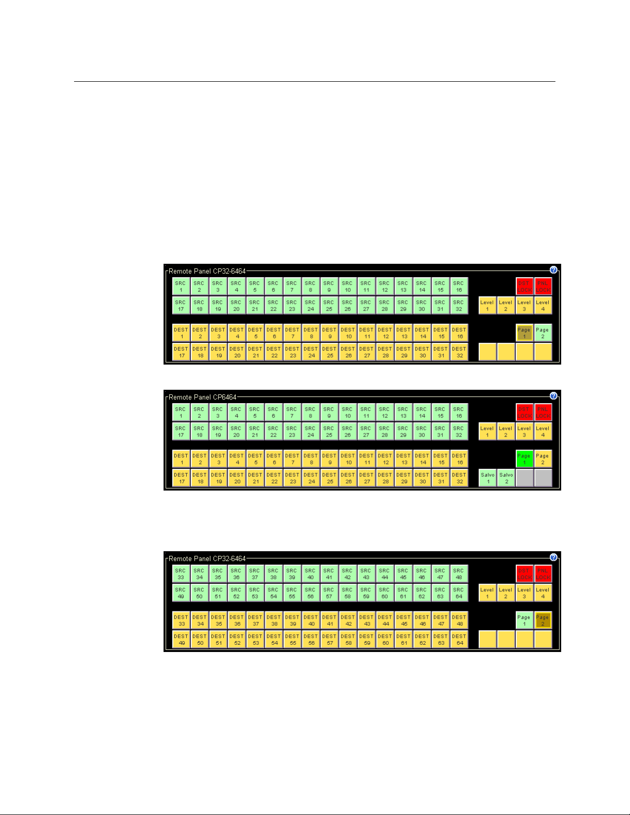
CR6400
User’s Guide
The terms ‘Display Sources’ and ‘Display Destinations’ denote that destination buttons are not
permitted on the page of source buttons and source buttons are not permitted on the page of
destination buttons. The ‘Display Page 1’ and ‘Display Page 2’ buttons do not have this
restriction.
Level buttons and salvo buttons are permitted anywhere.
Paging Button Types
• Display Page 1
This button causes functions 1–32 and 65–96 to appear on the 64-button array.
For the CP32-6464, this is a typical result (as represented by the configuration page which
shows the button functions):
For the CP6464, this is a typical result:
• Display Page 2
This button causes functions 1–32 and 65–96 to appear on the 64-button array.
For the CP32-6464, this is a typical result:
57
Page 68

CRSC Network Operation
Choosing a Button Page
For the CP6464, this is a typical result:
• Toggle Page 1 and Page 2
This toggle button switches the panel between the effects of the ‘Display Page 1’ and ‘Display Page 2’ buttons.
• Display Sources
This button applies only to the CP6464. It causes functions 1–64 to appear on the 64-button
array. In typical configurations, most of these are source buttons (green).
This is a possible result (here showing the buttons as represented in the configuration page
where the button functions are given):
• Display Destinations
This button applies only to the CP6464. It causes functions 65–128 to appear on the 64-button array. typical configurations, most of these are destination buttons (amber).
This is a possible result:
• Toggle Sources and Destinations
This toggle button switches the panel between the effects of the ‘Display Sources’ and ‘Display Destinations’ buttons.
58
Page 69

Performing Takes
49 50 51 52 53 54
55
64
33 34 35 36 37 38 39 48
17 18 19 20 21 22 23 32
1234567
16
A56A34A12SD
D
SRCDST
49
50 51 52 53 54
55
64
33
34 35 36 37 38 39 48
17
18 19 20 21 22 23 32
1
234567
16
A56A34A12SD
S
SRCDST
A take is the switching of a signal from a source to a destination. ‘Takes’ are performed using the
control panel; pressing buttons that have been configured to represent specific sources or destinations. Sources may only to taken to destinations on the same level.
For the CR6400 family routers and panels, there are 3 types of ‘takes’:
• Normal ‘takes’ have no breakaway; the source and destination are on the same level. See
Normal Takes
• A breakaway take has multiple sources on different levels to a destination. See Breakaway
Tak es on page 60.
• Single-destination ‘takes’ apply to the CP6401 which has only a default destination that can
neither be selected nor deselected. See Single-Destination Takes
Normal Takes
By “normal take” we mean a non-breakaway take.
First press a destination button and then a source button. The take occurs immediately. The
previous route (for the destination) is lost.
Please note:
• Takes on CP6401s are different. See Single-Destination Takes on page 65.
• If a destination is locked, the destination button is usually red, high-tally when selected. You
cannot perform a take for a destination that is locked. See Performing Locks
CR6400
User’s Guide
on page 59.
on page 65.
on page 68.
Example — Normal Take in Standard Mode
You want to route source S to destination D.
1 Optionally, select the levels on which you want the take to occur. Potentially, this changes
the sources and destinations enabled for the take. See Level Selection in Standard Mode
page 70. (Selecting levels prior to the destination does not result in breakaway.)
2 Switch to the page containing destination D. Press destination D.
3 Switch to the page containing source S. Press source S.
Pressing another destination button (always) starts a new take.
In standard mode, a normal take occurs on all selected levels.
on
59
Page 70

CRSC Network Operation
49 50 51 52 53 54
55
64
33 34 35 36 37 38 39 48
17 18 19 20 21 22 23 32
1234567
16
A56A34A12SD
D
SRCDST
49
50 51 52 53 54
55
64
33
34 35 36 37 38 39 48
17
18 19 20 21 22 23 32
1
234567
16
A56A34A12SD
S
SRCDST
Performing Takes
Example — Normal Take in Enhanced Mode
You want to route source S to destination D.
1Do not press any level buttons. Doing so initiates a breakaway for the previously chosen des-
tination.
2 Switch to the page containing destination D. Press destination D.
3 Switch to the page containing source S. Press source S.
Pressing another destination button (always) starts a new take.
In enhanced mode, a normal take occurs on all the levels defined for the destination.
Breakaway Takes
A breakaway takes multiple sources, on different levels, to a destination.
To perform a breakaway, first press a destination button. Then alternately press level buttons
(one or more) and then a source button, repeating for any levels for which you want to specify a
source. The takes occurs immediately when you press the source buttons. The previous route
(for that destination) is lost (on the levels you selected).
Please note:
• Takes on CP6401s are different. See Single-Destination Takes on page 65.
• If a destination is locked, the destination button is usually red, high-tally when selected. You
cannot perform a take for a destination that is locked. See Performing Locks
on page 68.
60
Page 71
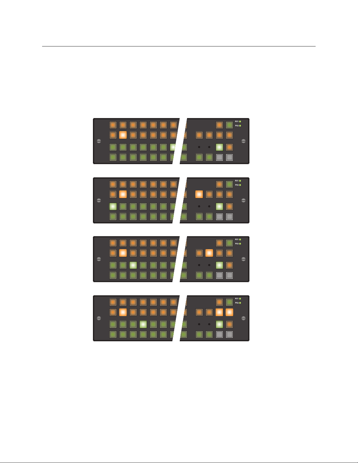
CR6400
49 50 51 52 53 54
55
64
33 34 35 36 37 38 39 48
17 18 19 20 21 22 23 32
1234567
16
A56A34A12SD
D2
P2P1
S7S4S3S1
49 50 51 52 53 54
55
64
33 34 35 36 37 38 39 48
17 18 19 20 21 22 23 32
1234567
16
A56A34A12SD
D2
P2P1
S7
S4
S3S1
49 50 51 52 53 54
55
64
33 34 35 36 37 38 39 48
17 18 19 20 21 22 23 32
1234567
16
A56A34A12SD
D2
P2P1
S7S4S3S1
49 50 51 52 53 54
55
64
33 34 35 36 37 38 39 48
17 18 19 20 21 22 23 32
1234567
16
A56A34A12SD
D2
P2P1
S7S4S3S1
User’s Guide
Example — Breakaway in Standard Mode
You want to take SD video from source S1 to destination D2. But you also want to take AES12
from source S3 and both AES34 and AES56 from source S4.
(Assume that these sources and destinations are enabled and remain enabled.)
The level buttons are SD, A12, A34, and A56.
1 Switch to the page containing destination D. Press destination D2. The previous source was
source S7 so it is high-tally.
2 Select level SD (only). Press source 1.
3 Select level A12 only. Press source S3.
4 Select levels A34 and A56 only. Press source S4.
Double-press any of the level buttons to make visible the source that contributes that level. (You
might have to switch pages to see the source.
You can continue to break sources away, ad infinitum, and you can come back to the destination
later and it will still show the breakaway. You could add or remove breakaway sources at that
time too.
61
Page 72
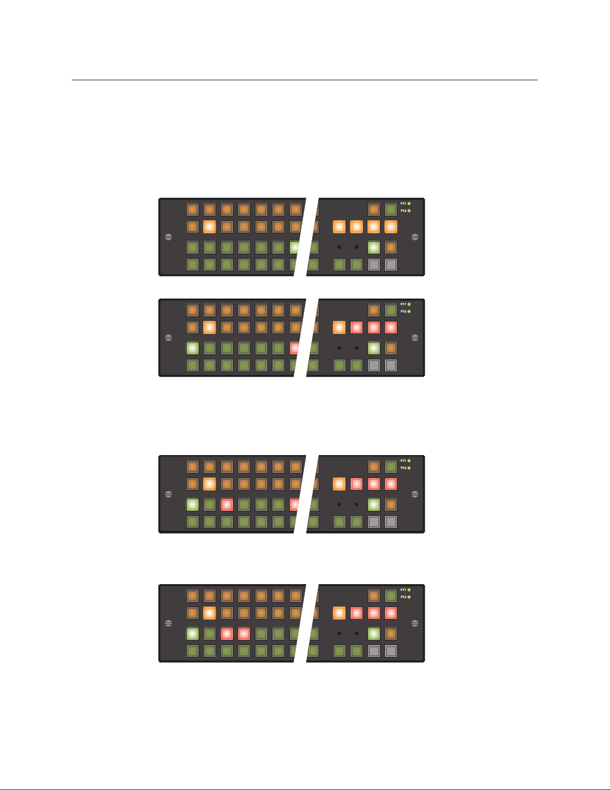
CRSC Network Operation
49 50 51 52 53 54
55
64
33 34 35 36 37 38 39 48
17 18 19 20 21 22 23 32
1234567
16
A56A34A12SD
D2
P2P1
S7S4S3S1
49 50 51 52 53 54
55
64
33 34 35 36 37 38 39 48
17 18 19 20 21 22 23 32
1234567
16
A56A34A12SD
D2
P2P1
S7S4S3S1
49 50 51 52 53 54
55
64
33 34 35 36 37 38 39 48
17 18 19 20 21 22 23 32
1234567
16
A56A34A12SD
D2
P2P1
S7S4S3S1
49 50 51 52 53 54
55
64
33 34 35 36 37 38 39 48
17 18 19 20 21 22 23 32
1234567
16
A56A34A12SD
D2
P2P1
S7S4S3S1
Performing Takes
Example — Breakaway in Enhanced Mode without Hold — Variant 1
You want to take SD video from source S1 to destination D2. But you also want to take AES12
from source S3 and both AES34 and AES56 from source S4.
The levels defined for the destination are SD, A12, A34, and A56. SD was defined first in the
destination description. Therefore it is considered the primary level.
1 Switch to the page containing destination D2. Press destination D2. The previous source was
source S7 so it is high-tally.
2 Select just level SD. Press source S1, switching to its page if necessary.
Source S1 is high-tally because you have taken SD
— the primary level — from this source.
Source S7 is red because the other levels still come from source S7. (The SD level button is
amber because SD is the primary level. The other level buttons are red because they are not
primary. All level buttons go high-tally once again, either red or amber.)
3 Select just level A12. Press source S3.
Source S3 goes high-tally red because it is not the primary source. All level buttons go hightally once again.
4 Select both A34 and A56 levels. Press source S4.
Source S4 goes high-tally red because, like source 3, it is not the primary source. All level buttons go high-tally once again. Source S7 goes dim because no other levels come from source
S7.
62
Page 73

CR6400
49 50 51 52 53 54
55
64
33 34 35 36 37 38 39 48
17 18 19 20 21 22 23
1234567
16
CTLA34A1 2HD
D2
P2P1
S6S4S1
49 50 51 52 53 54
55
64
33 34 35 36 37 38 39 48
17 18 19 20 21 22 23 32
1234567
16
CTLA34A1 2HD
D2
P2P1
S6S4S1
49 50 51 52 53 54
55
64
33 34 35 36 37 38 39 48
17 18 19 20 21 22 23 32
1234567
16
CTLA34A1 2HD
D2
P2P1
S6S4S1
User’s Guide
Pressing another source button without selecting a level would effect a new normal take,
undoing the breakaway you had created.
Pressing another destination button (always) starts a new take.
Example — Breakaway in Enhanced Mode without Hold — Variant 2
You want to take all levels from source S1 to destination D2 except CTRL, which is to come from
source S4. Destination D2 is presently connected to source S6.
The levels defined for the destination are HD, A12, A34 and CTL. HD was defined first in the
destination description. Therefore it is considered the primary level.
1 Switch to the page containing destination D2. Press destination D2. The previous source was
S6 so it is high-tally.
2 Do not press a level button. Press source S1.
Source S1 goes high tally because it provides all levels including the primary level. (All of the
level buttons are amber because all levels belong to the primary source.)
3 Press level CTL. Press source S4.
Source S4 goes high-tally red because it is not the primary source. All the level buttons go
high-tally. The CTL level button turns red because now CTL is not from the primary source.
The HD, A12, and A34 buttons remain amber because they are from the primary source.
Pressing another source button without selecting a level would would effect a new normal take,
undoing the breakaway you had created.
Pressing another destination button (always) starts a new take.
63
Page 74

CRSC Network Operation
49 50 51 52 53 54
55
64
33 34 35 36 37 38 39 48
17 18 19 20 21 22 23 32
1234567
16
A56A34A12SD
D2
P2P1
S7S4S3S1
49 50 51 52 53 54
55
64
33 34 35 36 37 38 39 48
17 18 19 20 21 22 23 32
1234567
16
A56A34A12SD
D2
P2P1
S7S4S3S1
49 50 51 52 53 54
55
64
33 34 35 36 37 38 39 48
17 18 19 20 21 22 23 32
1234567
16
A56A34A12SD
D2
P2P1
S7S4S3S1
49 50 51 52 53 54
55
64
33 34 35 36 37 38 39 48
17 18 19 20 21 22 23 32
1234567
16
A56A34A12SD
D2
P2P1
S7S4S3S1
Performing Takes
Example — Breakaway in Enhanced Mode with Hold
You want to take SD video from source S1 to destination D2. But you also want to take AES12
from source S3 and both AES34 and AES56 from source S4. The previous source was S7.
The levels defined for the destination are SD, A12, A34, and A56. SD was defined first in the
destination description. Therefore it is considered the primary level.
1 Switch to the page containing destination D2. Press destination D2. The previous source was
source S7 so it is high-tally.
2 Select just level SD. Press source S1, switching to a different page if necessary.
Source S1 goes high tally because you have taken SD
— the primary level — from this source.
Source S7 is red, indicating that the other levels still come from source S7. (The SD level button is amber because SD is the primary level. The other level buttons are red because they
are not primary. They are low-tally because this is hold mode and, thus far, SD remains the
only level selection.)
3 Select just level A12. Press source S3.
Source S3 goes high-tally red because it is not the primary source. The level buttons remain
unchanged. You could choose another source at this point if you made a mistake.
4 Select levels A34 and A56. Press source S4.
Source S4 goes high-tally red because, like source S3, it is not the primary source. The level
buttons remain unchanged. Again, you could choose another source at this point. Pressing
64
Page 75
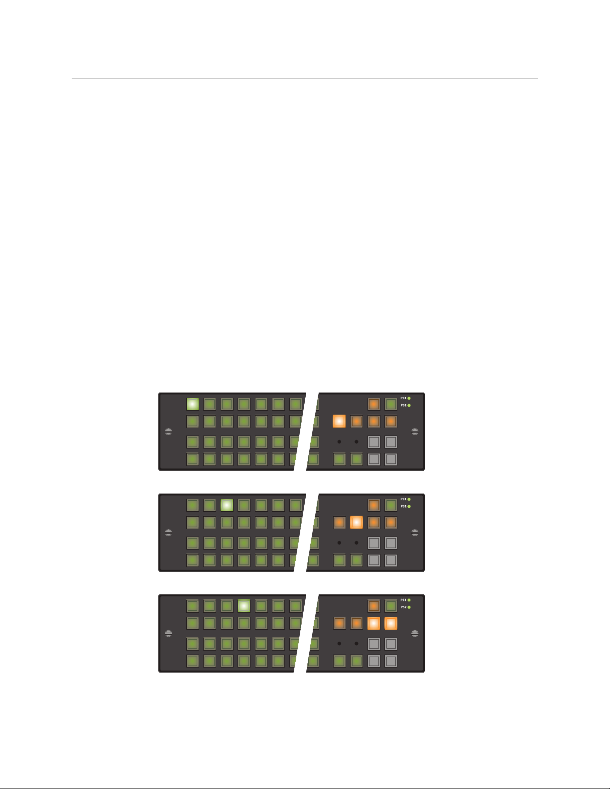
CR6400
49 50 51 52 53 54
55
64
33 34 35 36 37 38 39 48
17 18 19 20 21 22 23 32
1234567
16
A56A34A12SD
S3S1 S4 S7
49 50 51 52 53 54
55
64
33 34 35 36 37 38 39 48
17 18 19 20 21 22 23 32
1234567
16
A56A34A12SD
S3S1 S4 S7
49 50 51 52 53 54
55
64
33 34 35 36 37 38 39 48
17 18 19 20 21 22 23 32
1234567
16
A56A34A12SD
S3S1 S4 S7
User’s Guide
another source button without selecting another level simply changes the source for that
selected level (or levels).
Pressing another destination button (always) starts a new take. If you wish to clear the breakaway for destination D2, press destination D2, then press a source without selecting any levels.
Single-Destination Takes
Single-destination takes are slightly different. A CP6401 has only a default destination that can
neither be selected nor deselected.
Example — Normal Take for CP6401
You want to route source S to the default destination. Just press source S. It is a single button
press.
A normal take occurs on all the levels defined for the default destination.
Example — Breakaway for CP6401 in Standard Mode
You want to take SD from source S1 (to the default destination). But you also want to take AES12
from source S3 and both AES34 and AES56 from source S4.
(Assume that these sources and destinations are enabled and remain enabled.)
The level buttons are SD, A12, A34, and A56.
1 Select just level SD. Press source S1.
2 Select just level A12. Press source S3.
3 Select levels A34 and A56. Press source S4.
If these levels are selected, you can double-press any of the level buttons to make visible the
source that contributes that level.
65
Page 76
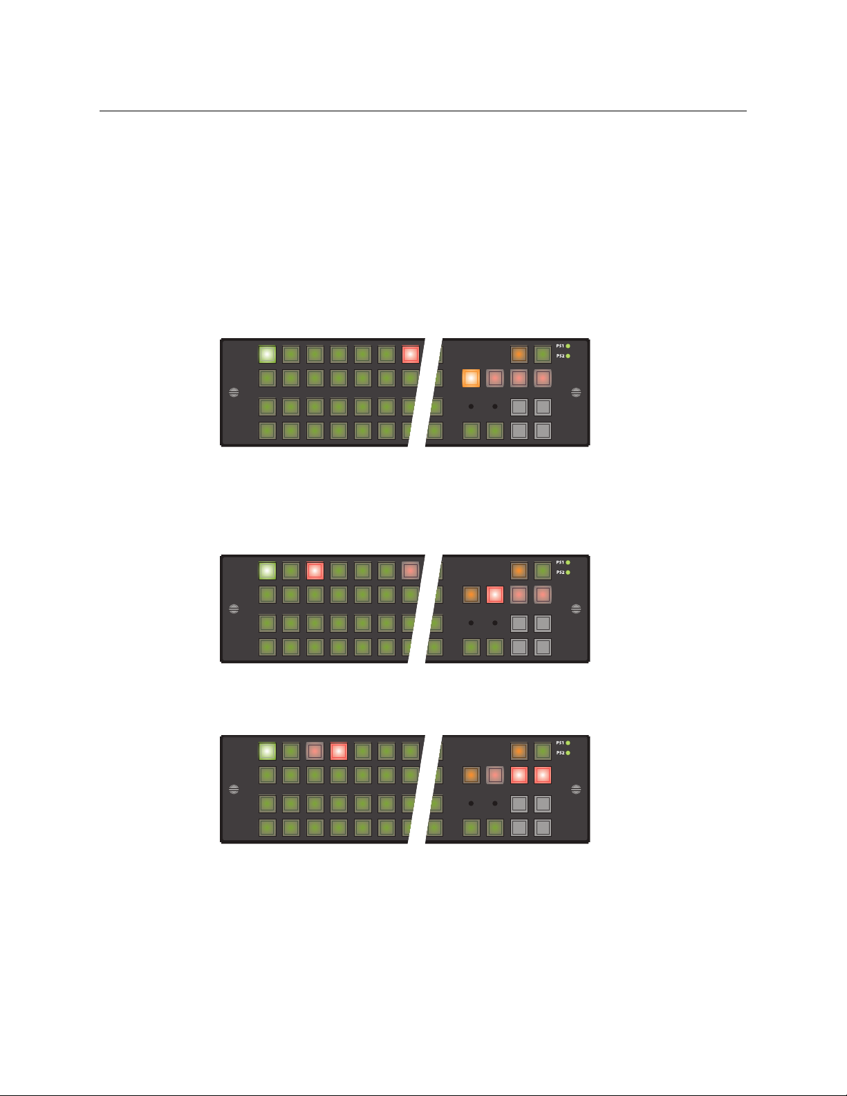
CRSC Network Operation
49 50 51 52 53 54
55
64
33 34 35 36 37 38 39 48
17 18 19 20 21 22 23 32
1234567
16
A56A34A12SD
S3S1 S4 S7
49 50 51 52 53 54
55
64
33 34 35 36 37 38 39 48
17 18 19 20 21 22 23 32
1234567
16
A56A34A12SD
S3S1 S4 S7
49 50 51 52 53 54
55
64
33 34 35 36 37 38 39 48
17 18 19 20 21 22 23 32
1234567
16
A56A34A12SD
S3S1 S4 S7
Performing Takes
You can continue to break sources away, ad infinitum.
To clear the breakaway, select all levels and then press a source.
Example — Breakaway for CP6401 in Enhanced Mode with Hold
You want to take SD from source 1 to the default destination. But you also want to take AES12
from source 3 and both AES34 and AES56 from source 4. The previous source was source 7.
The levels defined for the destination are SD, A12, A34, and A56. SD was defined first in the
destination description. Therefore it is considered the primary level.
This example shows a CP3201:
1 Select just level SD. Press source S1.
Source S1 goes high tally because you have taken SD
— the primary level — from this source.
Source S7 is red indicates that the other levels still come from source S7. (The SD level button
is amber because SD is the primary level. The other level buttons are red because they are
not primary. They are low-tally because this is hold mode and SD remains the selection.)
2 Select just A12. Press source S3.
Source 3 goes high-tally red because it is not the primary source. The level buttons remain
unchanged. You could choose another source at this point.
3 Select just A34 and A56. Press source S4.
Source S4 goes high-tally red because, like source S3, it is not the primary source. The level
buttons remain unchanged. Again, you could choose another source at this point. Pressing
another source button without selecting another level simply changes the source for that
selected level (or levels).
To clear the breakaway, select all levels for the default destination and then press a source.
66
Page 77

CR6400
49 50 51 52 53 54
55
64
33 34 35 36 37 38 39 48
17 18 19 20 21 22 23 32
1234567
16
A56A34A12SD
S3S1 S4 S7
49 50 51 52 53 54
55
64
33 34 35 36 37 38 39 48
17 18 19 20 21 22 23 32
1234567
16
A56A34A12SD
S3S1 S4 S7
49 50 51 52 53 54
55
64
33 34 35 36 37 38 39 48
17 18 19 20 21 22 23 32
1234567
16
A56A34A12SD
S3S1 S4 S7
User’s Guide
Example — Breakaway Take for CP3201 in Enhanced Mode without Hold
You want to take SD from source S1 to the default destination. But you also want to take AES12
from source S3 and both AES34 and AES56 from source S4. The previous source was S7.
The levels defined for the destination are SD, A12, A34, and A56. SD was defined first in the
destination description. Therefore it is considered the primary level.
1 Select just level SD. Press source S1.
Source S1 is high-tally because you have taken SD
— the primary level — from this source.
Source S7 is red because the other levels still come from S7. (The SD level button is amber
because SD is the primary level. The other levels are red because they are not primary.)
2 Select just A12. Press source S3.
Source S3 goes high-tally red because it is not the primary source. All level buttons go hightally once again.
3 Select both A34 and A56. Press source S4.
Source S4 goes high-tally red because, like source S3, it is not the primary source. All level
buttons go high-tally once again.
Pressing another source button without selecting a level reverts the take to a normal take,
clearing the breakaway you performed.
67
Page 78

CRSC Network Operation
64
48
32
16
PLDL
Performing Locks
Performing Locks
Panel Lock
Pressing a ‘Panel Lock’ button disables the control panel. Panel locks apply to all control panels,
including CQX panels. Only the ‘Panel Lock’ button remains enabled. Pressing it again reenables the control panel. Panel locks are available on all panels, including the CQX panel.
When the control panel is locked, the lock button is high tally red and the state of the entire
control panel is protected. Changes from the control panel are disabled.
Destination Locks
When the operator presses a ‘Destination Lock’ button, the current destination is locked to its
source(s). No operator may choose another source for that destination at any panel. Destination
locks are available on all panels, including the CQX panel.
A destination lock occurs on all the levels defined for the destination
have been deselected.
A simple lock protects a destination on all levels defined for the destination.
A complex lock protects a destination only on the levels defined for the destination that are
selected. Sources may still be taken to that destination on other levels.
Unlocking a locked destination can be simple or moderately complex.
Yo u can route the source that feeds a locked destination to any number of other destinations:
• A destination lock on a CP3201 or CP6401 is slightly different because such a panel has only
a “default destination.” See Single-Destination Locks and Unlocks
• You cannot unlock, at a panel, a destination locked by someone else. It is possible to release
those locks using CRSC. See Locks Page
• A destination might be locked (at another panel) on levels that you cannot see or control on
your panel. If that is the case, you cannot route any source to it.
except those levels that
on page 69.
on page 99.
Simple Locks
Press a destination, then press ‘Destination Lock’.
Under a simple lock, the destination button is:
• High-tally red when it is selected and at least one of the levels on which it is locked is
selected.
• High-tally amber when it is selected and none of the levels on which it is locked is selected.
• Dark (in standard mode) when none of its levels are selected. (The destination cannot be
selected.)
• Low-tally red when it is not selected.
68
Page 79

CR6400
User’s Guide
The ‘Destination Lock’ button is:
• High-tally red when the destination is selected and at least one of the levels on which it is
locked is selected.
• Low-tally amber otherwise.
To undo a simple lock, press the destination and then press ‘Destination Lock’.
Complex Locks
Press the button for a destination, then alternately select a level (or levels) and press ‘Destination Lock’.
Under a complex lock, the destination button is the same as for a simple lock:
• High-tally red when it is selected and at least one of the levels on which it is locked is
selected.
• High-tally amber when it is selected and none of the levels on which it is locked is selected.
• Low-tally red when it is not selected.
The ‘Destination Lock’ button is the same as for a simple lock.
• High-tally red when the destination is selected and at least one of the levels on which it is
locked is selected.
• Low-tally amber otherwise.
To undo a complex lock, select all locked levels, press the destination and then press ‘Destination Lock’. The level you select are unlocked if they are locked and locked if they are unlocked.
Single-Destination Locks and Unlocks
Because a CP6401 has only a default destination, locks are different.
Simple Lock
Select all levels and press the destination lock button. The panel’s destination is locked on all
levels defined for the destination: its current source(s) cannot be changed on any level.
The destination lock button remains red until you press it again to unlock the default
destination.
To undo a simple lock, select all levels and then press ‘Destination Lock’. You might have to press
the lock button twice. That is because the first press might accidentally lock a level you did not
know was unlocked.
Complex Lock
Select one or more levels and press the destination lock button. The panel’s destination is
locked on all selected levels: its current source(s) cannot be changed on any of those levels.
The destination lock button is high-tally red if you have selected any levels and low-tally amber
otherwise.
To undo a complex lock, select all levels and then press ‘Destination Lock’. You might have to
press the lock button twice. That is because the first press might actually lock a level you did not
know was unlocked.
To unlock a single locked level, select that level only and then press ‘Destination Lock’.
— CP6401
— CP6401
69
Page 80

CRSC Network Operation
Executing Salvos
Executing Salvos
A salvo is a pre-defined list of up to 32 basic ‘takes’. A salvo is assigned to a control panel button.
When the operator presses a salvo button, the ‘takes’ defined in the salvo execute in order.
Salvos do not loop and must not execute simultaneously. An attempt to run two or more salvos
at once will have unpredictable results.
Salvos are available on all panels except the CQX panel.
No instructions are required for pressing a salvo button. However, the configurer should let the
operator know at least what the general effect of the salvo is. Meaningful button labels help.
If a level specified in the salvo is not enabled, or if the input or output does not exist, the take(s)
on that level do not occur. Salvos with errors take longer to execute because of multiple
attempts to perform ‘takes’ and the resulting time-outs. There is no error reporting or warning if
a salvo fails at any point.
A salvo button goes high-tally when it is executing and returns to low-tally when the salvo
completes. As a rule of thumb, no salvo should require more than a few hundred milliseconds.
Performing Level Selection
Level buttons enable or disable levels. When a level button is high-tally, the level is enabled. The
levels enabled at any particular time are called the selected levels. A panel must have a level
button for each level it controls. The panel will not switch a source on a level for which there is
no level button. The exception to this is that when a panel has no level buttons, all levels defined
for the destination are selected. Level selection has no effect on routed signals until you perform
a take.
The result of level selection depends on panel mode: standard, enhanced with hold, or
enhanced without hold.
Level Selection in Standard Mode
A level selection affects all ‘takes’ made after the level selection. The levels you select persist
until you change them. This is true for normal ‘takes’ and for breakaway.
In most cases, the level buttons are toggles: press the level button to select the level if it is unselected or deselect the level if it is selected. However, there are 2 exceptions:
• When you have selected all the levels on the panel, pressing any level button deselects the
other levels and leaves the one you pressed selected.
• When you have only one level on your panel, pressing the level selection button has no
effect. The single level is always selected.
Level selection in standard mode is affected by button order.
Level selection in standard mode enables the selection of some sources and destinations and
disables other sources and destinations. The buttons of disabled sources and destinations are
turned off (dark).
70
Page 81
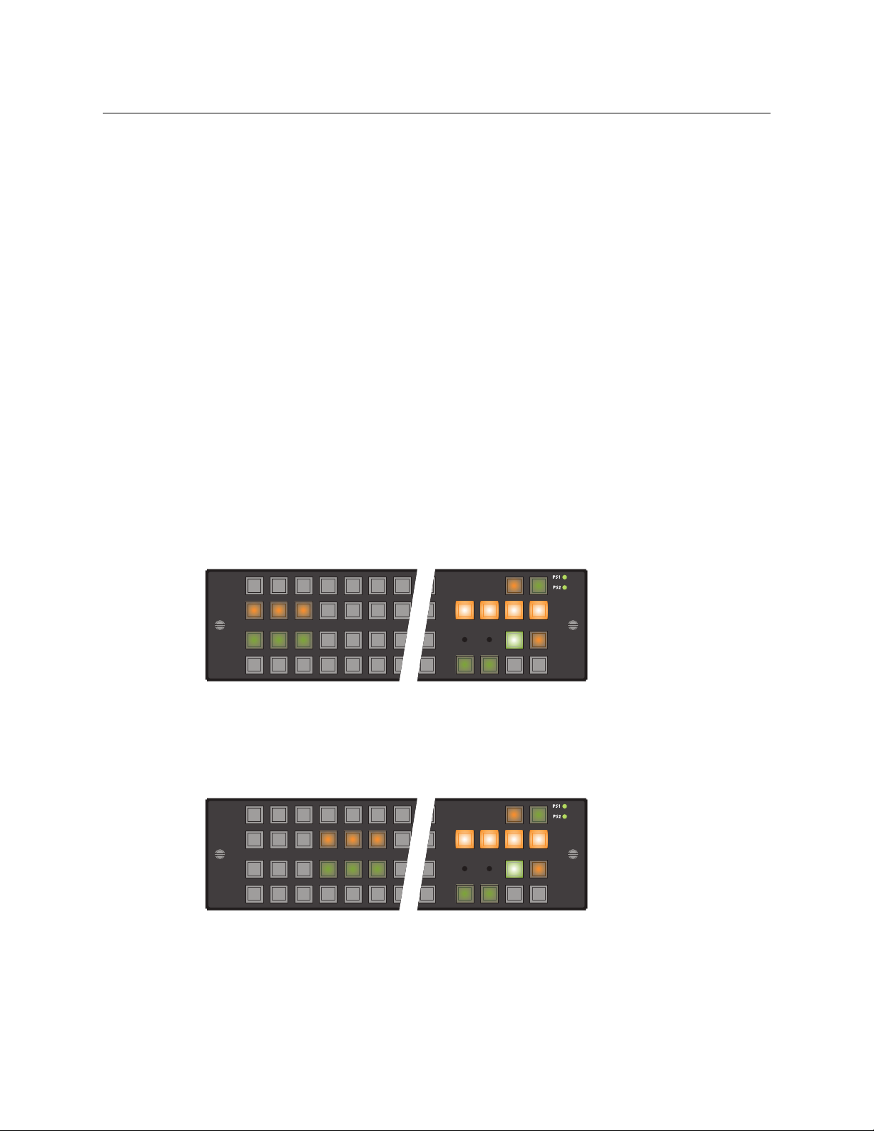
CR6400
49 50 51 52 53 54
55
64
33 34 35 36 37 38 39 48
17 18 19 20 21 22 23 32
1234567
16
SDTCA12AVAV2
P2P1
SD1AV3AV1 AV2 SD2 SD3
AV3 SD1 SD2 SD3AV1
49 50 51 52 53 54
55
64
33 34 35 36 37 38 39 48
17 18 19 20 21 22 23 32
1234567
16
AVA12TCSDAV2
P2P1
SD1AV3AV1 AV2 SD2 SD3
AV3 SD1 SD2 SD3AV1
User’s Guide
Button Order
The ordering of buttons on a panel affects the meaning of level selection under standard mode.
We call this spatial ordering.
The order in which the operator presses level buttons affects the meaning of level selection
under standard mode. We call this temporal ordering.
To illustrate, the following examples use a set of 6 sources and 6 destinations. Three of the
sources and three of the destinations have AV, AES, and TC levels. The remaining sources and
destinations have SD, AES, and TC levels. The four level buttons are AV, AES, TC, and SD.
Button order is important only in standard mode. The examples are for panels in standard mode.
In standard mode, pressing level buttons enables certain sources and destinations and disables
other sources and destinations. The button for a disabled source or destination is off. The operator may perform ‘takes’ only for enabled destinations and sources.
Spatial Ordering
Rule 1: when all levels are selected, the sources and destinations that are enabled are those that
include the level that is controlled by the level button with the lowest button number. If no
levels are selected, no sources and destinations are enabled.
The level on the level button with the lowest button number has precedence or priority over
other levels.
These examples show the difference between two orderings of level buttons. Figure 6-5 shows
level buttons in the order AV, AES, TC, SD:
Fig. 6-5: Spatial Ordering AV, AES, TC, SD
Level AV is on the left and has the lowest button number. Because all levels are selected, sources
and destinations that include level AV are enabled (low-tally) and other sources and destinations are disabled (buttons turned off ).
Figure 6-6 shows level buttons in the reverse order (SD, TC, AES, AV):
Fig. 6-6: Spatial Ordering SD, TC, AES, AV
Here, level SD is on the left and has the lowest button number. Again, all levels are selected.
Sources and destinations that include level SD are now enabled and other sources and destinations are disabled (buttons turned off ).
71
Page 82

CRSC Network Operation
49 50 51 52 53 54
55
64
33 34 35 36 37 38 39 48
17 18 19 20 21 22 23 32
1234567
16
SDTCA12AVAV2
P2P1
SD1AV3AV1 AV2 SD2 SD3
AV3 SD1 SD2 SD3AV1
49 50 51 52 53 54
55
64
33 34 35 36 37 38 39 48
17 18 19 20 21 22 23 32
1234567
16
SDTCA12AVAV2
P2P1
SD1AV3AV1 AV2 SD2 SD3
AV3 SD1 SD2 SD3AV1
Performing Level Selection
Thus, with one particular level button ordering, AV sources are enabled. With the other ordering,
SD sources are enabled.
If a panel’s level buttons are distrubuted across the panel, one should remember the ordering
method: (1) buttons in any row have higher precedence than buttons in lower rows and (2)
within a row, buttons to the left have higher precedence than any to the right.
Precedence determines
buttons are enabled for selection.
Tempora l O rderi n g
Rule 2: when not all levels are selected, the sources and destinations that are enabled are those
that include the level that you select last. If no levels are selected, no sources and destinations
are enabled.
Figure 6-7 shows level buttons again in the order AV, A12, TC, SD, but this time with level AV
unselected:
— for a panel in standard mode — which source and destination
Fig. 6-7: Temporal Ordering AES, TC, SD
Although it is not visually apparent, when the A12 button is pressed last, the sources and destinations that include A12 are enabled.
Figure 6-8 shows the same selected level buttons, but this time level SD was pressed last:
Fig. 6-8: Temporal Ordering AES, TC, SD
The same level buttons were pressed here as in Figure 6-7, but in different order with a very
different result. Sources and destinations that include level SD are enabled.
The Double-Press
To reselect a level, first deselect the level, then select the level. That is, press the level button
twice. You can considered this action a “double-press.”
A double-press gives the level precedence over other selected levels.
In the example of Figure 6-8, If you double-pressed A12, the result would again be like Figure 6-
7.
72
Page 83

CR6400
User’s Guide
Standard Mode Summary
Rule 1: when all levels are selected, the sources and destinations that are enabled are those that
include the level that is controlled by the level button with the lowest button number.
Rule 2: when not all levels are selected, the sources and destinations that are enabled are those
that include the level that you select last.
‘Takes’ occur on all selected levels. Destinations (and sources) are enabled by the level with
precedence:
• (Rule 1) precedence given by the lowest level button number.
• (Rule 2) precedence given by the most recently pressed level button.
‘Takes’ can occur only for enabled destinations and sources.
Level Selection in Enhanced Mode
In enhanced mode, level buttons do not enable or disable levels, but select levels. What enables
and disables the levels is the destination: whatever levels the destination includes are enabled
when you press the destination button to begin a take. These levels remain enabled during the
take. Other levels are disabled and remain disabled during the take.
Enhanced mode has two submodes: hold and no-hold. The submodes affect breakaway. In fact,
level selection applies only in breakaway:
• In no-hold mode, the selected levels persist only until you press a breakaway source. Then
they revert to the levels of the destination.
Not pressing a level button before pressing a source results in a normal take from that
source. It clears the breakaway condition during the take.
• In hold mode, the selected levels persist until you change the level selection or you press
another destination. (This allows the operator to try different sources.)
Clearing a breakaway condition during the take requires more effort in hold mode than in
no-hold mode.
Clearing a breakaway after a take (perhaps after many intervening ‘takes’ to other destinations)
is as simple as performing a normal take to a destination that has breakaway.
For normal ‘takes’ in enhanced mode, the levels selected are always exactly those included in
the destination’s level list.
In enhanced mode, all defined sources and destinations remain enabled without regard to level
selection. Button ordering (spatial or temporal) is not a factor in enhanced mode.
73
Page 84

CRSC Network Operation
Performing Level Selection
74
Page 85

Chapter 7 provides information regarding maintenance.
This document does not address maintenance of NV9000 equipment.
Topics
Prevention . . . . . . . . . . . . . . . . . . . . . . . . . . . . . . . . . . . . . . . . . . . . . . . . . . . . . . . . . . . . . . . . . . . . . . . . . . . . . . . 75
Trouble-Shooting
Prevention
The CR6400 routers and the CP6464 require little maintenance.
The CR6400 routers has removable (i.e., replaceable) modules, including a fan module.
The CP6464 has no serviceable parts.
We recommend that you keep your devices free of dust, water, and contaminants, and ensure
that cables are organized so that they do not short, kink, or break.
Check periodically that your power supplies are working, especially if you are using the second
power connections for redundancy.
Occasionally, Grass Valley releases new versions of Compact Router software and firmware. If
you order a new router and your existing routers have older software and firmware, the new and
the old products might be incompatible. If you experience difficulties with new routers, contact
Grass Valley to request software and firmware upgrades.
Update all your devices to the same firmware revision.
If a router fails, you can perform certain simple diagnostics. Call Grass Valley if the problem
cannot be solved easily.
Maintenance
. . . . . . . . . . . . . . . . . . . . . . . . . . . . . . . . . . . . . . . . . . . . . . . . . . . . . . . . . . . . . . . . . . . . . . . . . 75
Trouble-Shooting
If a CR6400 router or CP6464 malfunctions, first examine all input and output connections, all
network connections, and all power connections. Verify that cables are secure at both ends and
that they are not broken. Determine that video sources and destinations are powered on and
functioning properly. Verify that the video reference is functioning if you are using a reference.
If everything else in your system is functioning properly, the problem is at the device. Here are
some problems that can occur:
• The LED corresponding to your power supply connection does not illuminate.
• The fan LED is red or the reference LED is red.
(The reference LED is red when there is no video reference supplied. You may choose not to
use a video reference. In that case, you can ignore the reference LED.)
• The router gets power, but does not work properly or fails to “remember” its settings.
75
Page 86

Maintenance
Trouble-Shooting
Power Supply LED Does Not Illuminate
If the device is otherwise functioning properly, the problem is a faulty LED. (Call Grass Valley for
service.) If the router is not functioning at all, take the following steps.
Determine whether the external power supply delivers power. (If you cannot do this, call Grass
Valley.) If it does deliver power, try using the other PS connector. If neither connector works, the
router is “dead.” If one PS connector works and the other doesn’t, the router is defective.
The Grass Valley power supplies (part number PS0012-00) have an indicator lamp. If the indicator lamp is off, either the power supply is dead or the AC socket is defective or not connected.
Try plugging the power supply into another socket that you know is working. If the power
supply’s indicator light remains off, the power supply is dead. Otherwise, the AC socket was the
problem.
Noisy Transitions
Try using a video reference to align video (and audio) transitions with the sync in the video
reference.
Verify that the video reference signal is appropriate for the router, well-formed, and terminated.
If you use one of the composite analog signals (525 or 625) as a reference, you will probably
introduce switching transients. Because SMPTE specifies the switch point for HD as NTSC line
4, using a composite reference might cause the switch point to occur at the wrong place in
the HD stream. You might see switching transients. (The composite switch point is specified
as NTSC line 10.) Embedded audio will have a noticeable discontinuity.
Router Functioning Improperly
If the router gets power, but the router does not transmit signals properly or does not switch
properly, the router has an indeterminate problem. Call Grass Valley.
Level selection can be confusing: when all levels are selected, level buttons are not toggles.
Pressing a level button in this situation turns off all other levels and leaves the one you
selected on. This is by design. Please do not think this is a malfunction.
If a router malfunctions, try resetting the router. Set its rotary switch to 0 and cycle power. Doing
that restores the router to its factory default state.
A control panel powers up in ‘Panel Lock’ state. The ‘Panel Lock’ button at the top right is bright
red. Be sure to press ‘Panel Lock’ once (it turns low-tally green) so that the panel can operate.
Network Failure
Determine whether the Ethernet switch has power. If it has power, check whether the switch is
broken. A quick check is to see whether the switch’s activity lights are on or active.
Check the amber and green lights on the Ethernet port on your router or remote panel module.
These should be on and steady (not blinking).
Check your cables. They might be defective or of the wrong type. If your devices are very far
apart, the cable might be too long.
Again, check power.
76
Page 87

Chapter 8 provides electrical, video, audio, and mechanical specifications for the CR6400 family
products.
Topics
Power Specifications . . . . . . . . . . . . . . . . . . . . . . . . . . . . . . . . . . . . . . . . . . . . . . . . . . . . . . . . . . . . . . . . . . . . . . 77
Reference Specifications
Physical Specifications
Environmental Specifications
Connectors
Video Specifications
Audio Specifications
Drawings
Defaults
. . . . . . . . . . . . . . . . . . . . . . . . . . . . . . . . . . . . . . . . . . . . . . . . . . . . . . . . . . . . . . . . . . . . . . . . . . . . . . . 81
. . . . . . . . . . . . . . . . . . . . . . . . . . . . . . . . . . . . . . . . . . . . . . . . . . . . . . . . . . . . . . . . . . . . . . . . . . . . . . . . . 83
. . . . . . . . . . . . . . . . . . . . . . . . . . . . . . . . . . . . . . . . . . . . . . . . . . . . . . . . . . . . . . . . . . . . . . . . . . . . . . . . . . 88
Power Specifications
CR6400 Router Power Specifications
Technical Details
. . . . . . . . . . . . . . . . . . . . . . . . . . . . . . . . . . . . . . . . . . . . . . . . . . . . . . . . . . . . . . . . . . 78
. . . . . . . . . . . . . . . . . . . . . . . . . . . . . . . . . . . . . . . . . . . . . . . . . . . . . . . . . . . . . . . . . . . . 80
. . . . . . . . . . . . . . . . . . . . . . . . . . . . . . . . . . . . . . . . . . . . . . . . . . . . . . . . . . . . . 81
. . . . . . . . . . . . . . . . . . . . . . . . . . . . . . . . . . . . . . . . . . . . . . . . . . . . . . . . . . . . . . . . . . . . . . 82
. . . . . . . . . . . . . . . . . . . . . . . . . . . . . . . . . . . . . . . . . . . . . . . . . . . . . . . . . . . . . . . . . . . . . . 83
Specification Detail
Power consumption CR6464-3Gig, 77W maximum,
CR6464-AES, 55W maximum.
Regulatory UL listed and CE compliant.
Power Supply Specifications
Specification Detail
AC power 120–240 VAC, 50–60Hz, up to 2.0 A.
DC power 48VDC, 160 W max, 3.34A max
Ripple and Noise < 240mV p-p
Efficiency Typically 94%
Weight 1.45 lb (0.66 kg).
Regulatory UL listed and CE compliant.
77
Page 88

Technical Details
Pins 1 and 4 are +48V;
Pins 2 and 3 are ground, nominally 0V. The metal ring is ground also.
Reference Specifications
The power supply is Grass Valley part PS0012-00:
Fig. 8-1: Power Supply
Its power output has a 4-pin plug:
35.0
[1.38]
72.0
[2.83]
175.0 [2.83]
2
1
3
4
The power supply’s output is rated at 48 VDC, 160 W max, 3.34A max.
Its input is rated for 120–240VAC, 50–60Hz, and 2.0A.
See Power Cord Retention for the PS0012 Power Supply
Reference Specifications
CR6400 Video Reference Specifications
Detail
Connectors: 2 BNC (1 pair, loop-through), non-terminating, 75W characteristic imped-
ance. All digital routers (HD, SD, AES) accept these video reference rates:
Composite HD Tri-level
525i / 59.94
(NTSC)
625i / 50
(PAL)
720p / 23.98
720p / 24
720p / 25
720p / 29.97
720p / 30
720p / 50
720p / 59.94
720p / 60
1080i / 47.95
1080i / 48
1080i / 50
1080i / 59.94
1080i / 60
on page 89.
1080p / 23.98
1080p / 24
1080p / 25
1080p / 29.97
1080p / 30
1080p / 50
1080p / 59.94
1080p / 60
78
Input level range: 500
mV p-p to 2 V p-p. Input return loss: > 40 dB, to 6 MHz
Page 89

CR6400
User’s Guide
Compatibility between Video Formats and Reference Rates
Comp Tri-Level Sync
Video
Form at
525i / 59.94
625i / 50
720p / 23.98
720p / 24
720p / 25
720p / 29.97
720p / 30
720p / 50
720p / 59.94
720p / 60
1080psf / 23.98
1080psf / 24
1080psf / 29.97
1080psf / 30
1080i / 50
1080i / 59.94
1080i / 60
1080p / 23.98
1080p / 24
1080p / 25
1080p / 29.97
1080p / 30
1080p / 50
1080p / 59.94
1080p / 60
NTSC (525i59.94)
PAL (625i50)
720p / 23.98
720p / 24
720p / 25
720p / 29.97
720p / 30
720p / 50
720p / 59.94
720p / 60
1080i / 47.95
1080i / 48
1080i / 50
1080i / 59.94
1080i / 60
1080p / 23.98
1080p / 24
1080p / 25
1080p / 29.97
1080p / 30
1080p / 50
1080p / 59.94
1080p / 60
79
Page 90

Technical Details
Physical Specifications
Physical Specifications
CR6400 Router Specifications
Specification Detail
Dimensions Height: 3.47” (88.1mm), fits EIA 2 RU (3.50” or 88.9mm),
Depth 10.18 ± 0.01” (258.6 mm), enclosure.
Weight 11.8 lb (5.35 kg) with no I/O cards, without control panel.
Connectors Power: 2 connectors. See the drawing under Power Specifications on
Removable module 4 I/O card slots at rear
I/O module types SDI. AES
Grounding terminal Copper, accepts 14–6 AWG.
Width: 19.0” (482.6mm).
< 10.75” (273.1 mm) from front of rack to extended ground screw
15.3 lb (6.94kg) with 4 I/O cards, without control panel.
page 77.
Ethernet: 1 connector , 10/100BaseT, RJ-45 jack.
Serial: 1 connector, 9-pin D type, usage determined by software, SMPTE
207M.
Video reference: 2 connectors, BNC, 75W.
Two 2×60 connectors for optional control panel.
1 crosspoint card slot at rear
1 control card slot at rear
1 fan module removable at the front
CP6464 Control Panel Specifications
Specification Detail
Dimensions Height: 3.41” (86.6mm),
Width: 17.62” (447.5mm).
Depth 0.50” (12.7mm) enclosure,
0.82” (20.8mm) overall.
Weight 1.43 lb (0.65kg).
Connectors One 2×60 connector to the CR6400
80
Page 91

Environmental Specifications
5
1
6
9
Gnd
TX
RX+
Gnd
n.c.
Gnd
TX+
RX
Gnd
Environmental Specifications
Specification Detail
Operating temperature 0–45° C, ambient.
Relative humidity 0 to 90%, non-condensing.
Cooling Removable fan module (two fans).
Connectors
Serial Connector
The serial connector is on the control card.
The automation connector for the CR6400 routers has this pinout:
CR6400
User’s Guide
The connector is RS-485, but can be used as RS-422.
Customers who want to operate the router through an automation system or a control system
may contact Grass Valley technical support for information.
81
Page 92

Technical Details
Video Specifications
Video Specifications
CR6400 Digital Video Specifications1
Specification Detail
3Gig Auto re-clocking: 270 Mb/s, and 1.483, 1.485, 2.966, and 2.970 Gb/s, or
HD-SDI (SWB) Data rates: up to 1.5 Gbps, reclocking at 143, 177, 270, 360 & 540Mb/s
SD-SDI Data rates: auto reclocking at 143, 177, 270, 360 & 540Mb/s and auto-
auto bypass. Pass-through: 10
Mb/s to 3.0 Gb/s
Input & output impedance: 75W.
Input cable equalization
m, Belden 1694A or equivalent, 270 MB/s.
> 400
> 150 m, Belden 1694A or equivalent, at 1.5 GB/s.
m, Belden 1694A or equivalent, at 3.0 GB/s.
> 100
Input return loss: > 15
dB, 5 MHz to 1.5 GHz.
Output level: 800mV pp ± 10%.
Output offset: 0VDC ± 0.5V.
Output rise/fall time: < 135
ps.
Output overshoot: ≤ 10% of amplitude.
Output timing jitter: < 0.2 UI p-p.
Output alignment jitter: < 0.3
UI at 100 kHz
Output return loss: > 10 dB, 1.5 GHz to 3.0 GHz.
and 1.483 & 1.485Gb/s rates, automatic bypass for other rates.
Input & output impedance: 75W.
Input cable equalization: up to 150m Belden 1694A or equivalent cable,
at 1.483Gb/s and 1.485Gb/s, and 400m at 143–540 Mb/s.
Input return loss: > 15dB, 5MHz to 1.5 GHz.
Output level: 800mV pp ± 10%.
Output offset: 0VDC ± 0.5V.
Output rise/fall time: < 270ps (20% to 80%).
Output overshoot: < 10% of amplitude.
Output jitter: < 0.2 UI p-p.
Output return loss: > 15dB, 5MHz to 1.5 GHz.
matic bypass for other rates.
Input & output impedance: 75W.
Cable equalization: up to 300m Belden 1694A or equivalent cable.
Input return loss: ≥ 15dB, 5 to 540 MHz.
Output level: 800mV pp ± 10%.
Output offset: 0VDC ± 0.5V.
Output rise/fall time: 0.4 to 1.5 ns.
Output overshoot: ≤ 10% of amplitude.
Output jitter: ≤ 0.2 UI p-p.
Output return loss: ≥ 15dB, 5MHz to 540 MHz.
82
1. The CR6400 routers support DVB-ASI.
Page 93

Audio Specifications
CR6400 Digital Audio (AES) Specifications
Specification Detail
Signal inputs Signal type: AES3id (2 “mono” channels per input).
Signal outputs Signal type: AES3id (2 “mono” channels per input).
Sample rate: 32 kHz – 192 kHz.
Input level: 1V p-p nominal into 75 W.
Input range: 200 mVp-p to 3 V p-p into 75 W.
Input return loss: < –25 dB, from 100kHz to 6 MHz.
Input connectors: BNC, 75 W.
Sample rate: async, 32 kHz
Output level: 1V p-p ± 10% into 75W.
Output offset: 0.0VDC±50mVDC, AC coupled.
Output rise/fall time: 4 ns
Output jitter: < 1ns, in synchronous mode.
Output return loss: < –25 dB, from 100kHz to 6 MHz.
Output-to-output isolation: > 40 dB, from 100 kHz to 6 MHz.
Output connectors: BNC, 75 W.
– 192 kHz; sync, 48 kHz.
– 8ns.
CR6400
User’s Guide
Drawings
The following drawings identify features and provide overall and critical dimensions.
83
Page 94

Screw Holes for Control Panel (2)
Cover Plate over Control
Panel Connec
16-Pos. Rotary Switch
Power LEDs (2)
Fan Module (Removable)
Video Reference LED
Fan Alarm LED
3.47
[88.1]
3.00
[76.2]
16.74 [425.2]
19.0 [482.6]
Technical Details
Drawings
84
Fig. 8-2: Front View of the CR6400 Family Routers
Page 95

Control Card
Ethernet
RS-422
64 Outputs, DIN 1.0/2.3 (coax)
PS1, PS2
GND Lug
64 Inputs, DIN 1.0/2.3 (coax)
Crosspoint Card
I/O Cards (4, 3Gig)
Video Reference,
(2, BNC 75W)
3.47
[88.1]
3.00
[76.2]
17.48 [444.0]
19.0 [482.6]
0.76 [19.3]
CR6400
User’s Guide
Fig. 8-3: Rear Views of the CR6464-3Gig Router
85
Page 96

Technical Details
AES I/O
AES I/O
AES I/O
AES I/O
Control Card
Ethernet
RS-422
64 Outputs, DIN 1.0/2.3 (coax)
PS1, PS2
GND Lug
64 Inputs, DIN 1.0/2.3 (coax)
Crosspoint Card
I/O Cards (4, 3Gig)
Video Reference,
(2, BNC 75W)
3.47
[88.1]
3.00
[76.2]
17.48 [444.0]
19.0 [482.6]
0.76 [19.3]
Drawings
86
Fig. 8-4: Rear Views of the CR6464-AES Router
Page 97

CR6400
Panel Lock Button
Selection Buttons (1–64)
Destination Lock Button
Power Supply LEDs
Knurled Screws (2x)
Connector to Router
Level Selection Buttons 1–4
Fan LED
Video Reference LED
Source Mode
Destination Mode
0.50[12.7]
17.62 [447.5]
16.74 [425.2]
3.41
[86.6]
1.705
[43.3]
0.82[20.8]
User’s Guide
Fig. 8-5: Front and Top Views of the CP6464 Control Panel
87
Page 98

Technical Details
Defaults
Defaults
Default Router State
The factory-default state is to be in stand-alone mode.
The default routing state of a compact router is for input 1 to connect to output 1, input 2 to
connect to output 2, and so on for all inputs and outputs. This is called a diagonal routing. (After
you have made routing changes, the power-up state of the inputs and outputs is the state you
last created.)
If the router’s rotary switch is at position 0, the router will reset to its factory-default state at
power-up.
Initial Control Panel State
The initial control panel state at power up is “Panel Lock” with all levels selected. Before
performing an operation on any control panel (remote or local) you must turn off its panel lock.
Remember that a Panel Lock button locks that panel. It does not lock a router, other control
panels, or a network.
88
Page 99

Misc. Topics
Chapter 9 provides the following.
Topics
Power Cord Retention for the PS0012 Power Supply . . . . . . . . . . . . . . . . . . . . . . . . . . . . . . . . . . . . . . . 89
Power Cord Retention for the PS0012 Power Supply
Use the supplied retention strap to keep the AC power cord firmly connected to the power
supply. Follow these steps to use the strap:
1 Firmly insert the AC power cord into the power supply. Examine the last figure in this section
to see how the strap should be applied.
2 Placed the Velcro retention strap, fuzzy side up, on top of the power supply with the buckle
loop approximately 1 inch from the AC input side and the remaining strap around the cord
end and down:
3 Holding the buckle in place, lift the strap up and around the cord end so the strap overlaps
itself:
4 Holding the buckle loop in place, route the strap around the back of the supply diagonally
across so that it sticks out on the left below the output cord:
89
Page 100
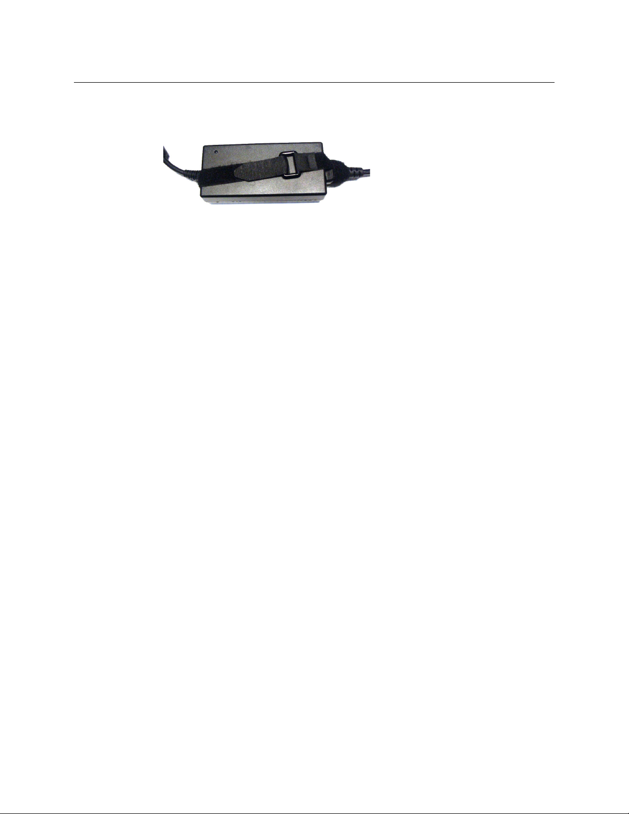
Misc. Topics
Power Cord Retention for the PS0012 Power Supply
5 Continue the strap around toward the buckle loop and through the loop. Cinch the strap
tightly. While keeping tension, place the 2 inch strap end (with Velcro loops) down on the
fuzzy part to complete the process:
6 Examine the strap though its path around the cord and power supply. Be sure that no slack
exists and that it is tight the full length of the strap. If necessary, adjust and cinch it more
tightly.
90
 Loading...