

Page 1

CopperHead Pro User Guide
M4013-9900-102
24 July 2014
Page 2

Notices
Copyright & Trademark Notice
Copyright © 2011–2014, Grass Valley. All rights reserved.
Belden, Belden Sending All The Right Signals, and the Belden logo are trademarks or
registered trademarks of Belden Inc. or its affiliated companies in the United States and
other jurisdictions. Grass Valley, CopperHead Pro are trademarks or registered trademarks
of Grass Valley. Belden Inc., Grass Valley, and other parties may also have trademark rights
in other terms used herein.
Terms and Conditions
Please read the following terms and conditions carefully. By using CopperHead Pro
documentation, you agree to the following terms and conditions.
Grass Valley, a Belden Brand (“Grass Valley”) hereby grants permission and license to owners
of CopperHead Pro to use their product manuals for their own internal business use.
Manuals for Grass Valley products may not be reproduced or transmitted in any form or by
any means, electronic or mechanical, including photocopying and recording, for any
purpose unless specifically authorized in writing by Grass Valley.
A Grass Valley manual may have been revised to reflect changes made to the product
during its manufacturing life. Thus, different versions of a manual may exist for any given
product. Care should be taken to ensure that one obtains the proper manual version for a
specific product serial number.
Information in this document is subject to change without notice and does not represent a
commitment on the part of Grass Valley.
Warranty information is available in the Support section of the Grass Valley Web site
(www.miranda.com).
Title CopperHead Pro User Guide
Part Number M4013-9900-102
Revision 24 July 2014
ii
Page 3

Table of Contents
1 About CopperHead Pro . . . . . . . . . . . . . . . . . . . . . . . . . . . . . . . . . 1
About CopperHead Pro . . . . . . . . . . . . . . . . . . . . . . . . . . . . . . . . . . . . . . . . . . . . . . . . . . . . . . . . . . . . 2
CopperHead System Features. . . . . . . . . . . . . . . . . . . . . . . . . . . . . . . . . . . . . . . . . . . . . . . . . . 2
Unpacking the CopperHead Pro . . . . . . . . . . . . . . . . . . . . . . . . . . . . . . . . . . . . . . . . . . . . . . . . . . . 3
Product Returns . . . . . . . . . . . . . . . . . . . . . . . . . . . . . . . . . . . . . . . . . . . . . . . . . . . . . . . . . . . . . . . 4
About this User Guide . . . . . . . . . . . . . . . . . . . . . . . . . . . . . . . . . . . . . . . . . . . . . . . . . . . . . . . . . 4
Safety and Fiber Optic Systems . . . . . . . . . . . . . . . . . . . . . . . . . . . . . . . . . . . . . . . . . . . . . . . . . . . . 4
Optical Fiber Safety. . . . . . . . . . . . . . . . . . . . . . . . . . . . . . . . . . . . . . . . . . . . . . . . . . . . . . . . . . . . 4
Power Fuses. . . . . . . . . . . . . . . . . . . . . . . . . . . . . . . . . . . . . . . . . . . . . . . . . . . . . . . . . . . . . . . . . . . 4
2 System Overview . . . . . . . . . . . . . . . . . . . . . . . . . . . . . . . . . . . . . . . 5
CopperHead Pro System Configurations. . . . . . . . . . . . . . . . . . . . . . . . . . . . . . . . . . . . . . . . . . . . 6
Dry Fiber Systems - Locally powered cameras . . . . . . . . . . . . . . . . . . . . . . . . . . . . . . . . . . 6
PowerWafer, Direct to Base Station . . . . . . . . . . . . . . . . . . . . . . . . . . . . . . . . . . . . . . . . . . . . 6
Power Wafer, Remote Panel-Mounted Fiber Connector . . . . . . . . . . . . . . . . . . . . . . . . 7
PowerWafer, with MPS Power Supply . . . . . . . . . . . . . . . . . . . . . . . . . . . . . . . . . . . . . . . . . . 8
PowerPlus - High Power/Long Distance with HDX Power Supply . . . . . . . . . . . . . . . 9
CopperHead Pro Transceiver System Components. . . . . . . . . . . . . . . . . . . . . . . . . . . . . . . . .10
Base Station Overview . . . . . . . . . . . . . . . . . . . . . . . . . . . . . . . . . . . . . . . . . . . . . . . . . . . . . . . .11
Types of Base Stations . . . . . . . . . . . . . . . . . . . . . . . . . . . . . . . . . . . . . . . . . . . . . . . . . . . . . . . .12
Single “Dry” Station . . . . . . . . . . . . . . . . . . . . . . . . . . . . . . . . . . . . . . . . . . . . . . . . . . . . . . . . . . 12
Dual Unpowered Base Station . . . . . . . . . . . . . . . . . . . . . . . . . . . . . . . . . . . . . . . . . . . . . . . . 12
Powered Base Station . . . . . . . . . . . . . . . . . . . . . . . . . . . . . . . . . . . . . . . . . . . . . . . . . . . . . . . . 12
3 CopperHead System Components . . . . . . . . . . . . . . . . . . . . . . 13
Camera Unit. . . . . . . . . . . . . . . . . . . . . . . . . . . . . . . . . . . . . . . . . . . . . . . . . . . . . . . . . . . . . . . . . . . . . .14
Camera Unit - Front Side. . . . . . . . . . . . . . . . . . . . . . . . . . . . . . . . . . . . . . . . . . . . . . . . . . . . . .14
Camera Unit - Signal Status Panel (Section A) . . . . . . . . . . . . . . . . . . . . . . . . . . . . . . . . . 15
Camera Unit - Intercom Controls (Section B) . . . . . . . . . . . . . . . . . . . . . . . . . . . . . . . . . 16
Camera Unit - Power Switch & Indicator (Section C) . . . . . . . . . . . . . . . . . . . . . . . . . . . 16
Camera Unit - Camera Mounting Plate (Section D) . . . . . . . . . . . . . . . . . . . . . . . . . . . . 17
Camera Unit - Rear Side. . . . . . . . . . . . . . . . . . . . . . . . . . . . . . . . . . . . . . . . . . . . . . . . . . . . . . .18
Camera Unit - Connectors (Section A). . . . . . . . . . . . . . . . . . . . . . . . . . . . . . . . . . . . . . . . . 19
Camera Unit - Fiber Connector/Swivel (Section B) . . . . . . . . . . . . . . . . . . . . . . . . . . . . . 20
Camera Unit - Battery Mount (Section C) . . . . . . . . . . . . . . . . . . . . . . . . . . . . . . . . . . . . . . 20
Base Station . . . . . . . . . . . . . . . . . . . . . . . . . . . . . . . . . . . . . . . . . . . . . . . . . . . . . . . . . . . . . . . . . . . . . .21
Base Station Front Panel . . . . . . . . . . . . . . . . . . . . . . . . . . . . . . . . . . . . . . . . . . . . . . . . . . . . . .21
Front Panel Section A - Signal Status Indicators . . . . . . . . . . . . . . . . . . . . . . . . . . . . . . . 21
Front Panel Section B- Power Switch and Indicator . . . . . . . . . . . . . . . . . . . . . . . . . . . . 22
Front Panel Section C- Hybrid Power Status Indicators . . . . . . . . . . . . . . . . . . . . . . . . 23
Base Station Rear Panel . . . . . . . . . . . . . . . . . . . . . . . . . . . . . . . . . . . . . . . . . . . . . . . . . . . . . . .24
iii
Page 4

Table of Contents
Rear Panel Section A - Power Connector . . . . . . . . . . . . . . . . . . . . . . . . . . . . . . . . . . . . . . 24
Rear Panel Section B - Optical Connector . . . . . . . . . . . . . . . . . . . . . . . . . . . . . . . . . . . . . 25
Rear Panel Section C - Signal Connectors . . . . . . . . . . . . . . . . . . . . . . . . . . . . . . . . . . . . . 26
PowerWafer Camera Adaptor . . . . . . . . . . . . . . . . . . . . . . . . . . . . . . . . . . . . . . . . . . . . . . . . . . . . .27
MPS External PowerWafer Power Supply . . . . . . . . . . . . . . . . . . . . . . . . . . . . . . . . . . . . . . . . . .28
PowerPlus 3000 - Camera Power Adaptor . . . . . . . . . . . . . . . . . . . . . . . . . . . . . . . . . . . . . . . . .30
HDX Power Supply . . . . . . . . . . . . . . . . . . . . . . . . . . . . . . . . . . . . . . . . . . . . . . . . . . . . . . . . . . . . . . .33
HDX Status Indicators . . . . . . . . . . . . . . . . . . . . . . . . . . . . . . . . . . . . . . . . . . . . . . . . . . . . . . . .34
4 Camera Unit and Power Supply Installation . . . . . . . . . . . . . 35
Mounting the Copperhead Camera Unit with the PowerWafer . . . . . . . . . . . . . . . . . . . . .36
Mounting the CopperHead Pro Camera Unit with a battery . . . . . . . . . . . . . . . . . . . .36
Mounting the CopperHead Pro Camera Unit with the PowerWafer . . . . . . . . . . . . .37
Mounting the CopperHead Pro Camera Unit with the PowerPlus. . . . . . . . . . . . . . .38
Connecting the CopperHead Pro System . . . . . . . . . . . . . . . . . . . . . . . . . . . . . . . . . . . . . . . . . .40
Connecting Camera Unit to a Camera or Camcorder . . . . . . . . . . . . . . . . . . . . . . . . . . .40
Connecting Base Station to Studio Infrastructure . . . . . . . . . . . . . . . . . . . . . . . . . . . . . .42
Intercom connectivity . . . . . . . . . . . . . . . . . . . . . . . . . . . . . . . . . . . . . . . . . . . . . . . . . . . . . . . .43
Fiber Connections between the Base Station and Camera Unit . . . . . . . . . . . . . . . . .44
Tactical Fiber between Base Station (powered) and Camera Unit. . . . . . . . . . . . . . .45
SMPTE Hybrid Fiber between Base Station (powered) and Camera Unit . . . . . . . .45
Hybrid Fiber between Base Station (powered) and Camera Unit. . . . . . . . . . . . . . . .46
Hybrid Fiber Cable between MPS Power Unit and Camera Unit. . . . . . . . . . . . . . . . .46
SMPTE Hybrid Fiber between HDX Power Supply and Camera Unit. . . . . . . . . . . . .48
Deployment of the CopperHead System . . . . . . . . . . . . . . . . . . . . . . . . . . . . . . . . . . . . . . . . . .49
Insuring a Positive Fiber Link. . . . . . . . . . . . . . . . . . . . . . . . . . . . . . . . . . . . . . . . . . . . . . . . . . . . . .49
Intercom Operation . . . . . . . . . . . . . . . . . . . . . . . . . . . . . . . . . . . . . . . . . . . . . . . . . . . . . . . . . . . . . .50
Shutting Down the System . . . . . . . . . . . . . . . . . . . . . . . . . . . . . . . . . . . . . . . . . . . . . . . . . . . . . . .51
Troubleshooting . . . . . . . . . . . . . . . . . . . . . . . . . . . . . . . . . . . . . . . . . . . . . . . . . . . . . . . . . . . . . . . . .52
5 Specifications . . . . . . . . . . . . . . . . . . . . . . . . . . . . . . . . . . . . . . . . . 53
A Fiber Optic Systems . . . . . . . . . . . . . . . . . . . . . . . . . . . . . . . . . . . . 58
Basic Concepts . . . . . . . . . . . . . . . . . . . . . . . . . . . . . . . . . . . . . . . . . . . . . . . . . . . . . . . . . . . . . . . . . . .59
Fiber Optic Cable . . . . . . . . . . . . . . . . . . . . . . . . . . . . . . . . . . . . . . . . . . . . . . . . . . . . . . . . . . . . .59
Fiber Optic Connector Types. . . . . . . . . . . . . . . . . . . . . . . . . . . . . . . . . . . . . . . . . . . . . . . . . .60
A Brief Guide to Measurement of Fiber Optic Signal Strength . . . . . . . . . . . . . . . . . . . . . .61
B CopperHead Pro System Connectors . . . . . . . . . . . . . . . . . . . . 62
Camera Unit Connectors. . . . . . . . . . . . . . . . . . . . . . . . . . . . . . . . . . . . . . . . . . . . . . . . . . . . . . . . . .63
Camera Remote and Tally. . . . . . . . . . . . . . . . . . . . . . . . . . . . . . . . . . . . . . . . . . . . . . . . . . . . .63
Camera Headset. . . . . . . . . . . . . . . . . . . . . . . . . . . . . . . . . . . . . . . . . . . . . . . . . . . . . . . . . . . . . .64
PowerWafer Connector . . . . . . . . . . . . . . . . . . . . . . . . . . . . . . . . . . . . . . . . . . . . . . . . . . . . . .64
Base Station Connectors . . . . . . . . . . . . . . . . . . . . . . . . . . . . . . . . . . . . . . . . . . . . . . . . . . . . . . . . . .65
AC Power Input Connector- Models CHG3-BS-Pro-95VD-xxx-xxx . . . . . . . . . . . . . . .65
12VDC Input Power Connectors - Models CHG3-BS-Pro-2ST/2MX/NEU . . . . . . . . .65
iv
Page 5

System Monitor (future use) . . . . . . . . . . . . . . . . . . . . . . . . . . . . . . . . . . . . . . . . . . . . . . . . . .66
95VDC output: Model CHG3-BS-PRO-95VD-STM-xxx . . . . . . . . . . . . . . . . . . . . . . . . . .66
Base Station Remote/Tally Connector . . . . . . . . . . . . . . . . . . . . . . . . . . . . . . . . . . . . . . . . . . . . .67
4-Wire Intercom . . . . . . . . . . . . . . . . . . . . . . . . . . . . . . . . . . . . . . . . . . . . . . . . . . . . . . . . . . . . . .67
Clear-Com Intercom . . . . . . . . . . . . . . . . . . . . . . . . . . . . . . . . . . . . . . . . . . . . . . . . . . . . . . . . . .68
RTS Intercom. . . . . . . . . . . . . . . . . . . . . . . . . . . . . . . . . . . . . . . . . . . . . . . . . . . . . . . . . . . . . . . . .68
PowerWafer Connector . . . . . . . . . . . . . . . . . . . . . . . . . . . . . . . . . . . . . . . . . . . . . . . . . . . . . . . . . . .69
PowerPlus Connectors. . . . . . . . . . . . . . . . . . . . . . . . . . . . . . . . . . . . . . . . . . . . . . . . . . . . . . . . . . . .69
PowerPlus 12VDC Output Connector. . . . . . . . . . . . . . . . . . . . . . . . . . . . . . . . . . . . . . . . . .69
PowerPlus 24VDC Output Connectors. . . . . . . . . . . . . . . . . . . . . . . . . . . . . . . . . . . . . . . . .69
MPS Power Supply Connector . . . . . . . . . . . . . . . . . . . . . . . . . . . . . . . . . . . . . . . . . . . . . . . . . . . .70
AC Power Input Connector . . . . . . . . . . . . . . . . . . . . . . . . . . . . . . . . . . . . . . . . . . . . . . . . . . .70
C Cables, Parts, and Accessories. . . . . . . . . . . . . . . . . . . . . . . . . . . 72
Camera Unit & Base Station Interface Cables. . . . . . . . . . . . . . . . . . . . . . . . . . . . . . . . . . . . . . .73
CHCR-PRO Camera Unit Remote Cable . . . . . . . . . . . . . . . . . . . . . . . . . . . . . . . . . . . . . . . .73
CHBR-PRO Base Station Remote Cable . . . . . . . . . . . . . . . . . . . . . . . . . . . . . . . . . . . . . . . .74
Parts & Accessories . . . . . . . . . . . . . . . . . . . . . . . . . . . . . . . . . . . . . . . . . . . . . . . . . . . . . . . . . . . . . . .75
CopperHead Pro
User Guide
D Overview Diagrams . . . . . . . . . . . . . . . . . . . . . . . . . . . . . . . . . . . . 78
Camera Unit. . . . . . . . . . . . . . . . . . . . . . . . . . . . . . . . . . . . . . . . . . . . . . . . . . . . . . . . . . . . . . . . . . . . . .79
Base Stations . . . . . . . . . . . . . . . . . . . . . . . . . . . . . . . . . . . . . . . . . . . . . . . . . . . . . . . . . . . . . . . . . . . . .80
Base Station: 12Volt DC (single/dual) . . . . . . . . . . . . . . . . . . . . . . . . . . . . . . . . . . . . . . . . . .80
Base Station: 120/200 Volt AC (single only) . . . . . . . . . . . . . . . . . . . . . . . . . . . . . . . . . . . .81
v
Page 6

Table of Contents
vi
Page 7

About CopperHead Pro
This chapter provides an overview of the CopperHead Pro and includes the safety and
warranty information about it.
About CopperHead Pro . . . . . . . . . . . . . . . . . . . . . . . . . . . . . . . . . . . . . . . . . . . . . . . . . . . . . . . . . . . . . . . . 2
Unpacking the CopperHead Pro . . . . . . . . . . . . . . . . . . . . . . . . . . . . . . . . . . . . . . . . . . . . . . . . . . . . . . . 3
Safety and Fiber Optic Systems . . . . . . . . . . . . . . . . . . . . . . . . . . . . . . . . . . . . . . . . . . . . . . . . . . . . . . . . 4
1
Page 8
About CopperHead Pro
About CopperHead Pro
About CopperHead Pro
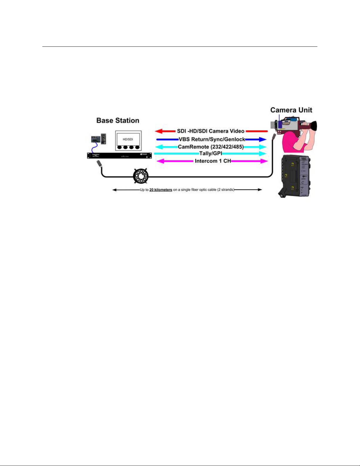
The CopperHead System is a fiber optic transmission system that enables camcorders to be
used in live, multi-camera production environments.
The system uses a fiber optic cable to transport a variety of signals between a Camera Unit
and a Base Station.
The CopperHead Pro Camera Unit is typically mounted to a camera that is placed in a
studio, theatre, sports venue, or other live-event location. The system's Base Station is
usually located in a truck, control room, or other video production control area.
When "dry" fiber is used (typically lightweight "tactical" fiber cable), the signals are
transmitted bi-directionally over distances as long as 5 km or more.
When you use a hybrid fiber cable, the link also provides power to the Camera Unit and the
camera itself.
CopperHead System Features
• Makes any camcorder practical for multi-camera production
• All camera signals are carried on one lightweight fiber cable
• Can be run through building or campus infrastructure on two strands of Single Mode
fiber*
• Thin, lightweight, modular design
• Studio quality uncompressed HD/SDI video up to 3 Gb/s
• Multi-kilometer distance capability
• Anton/Bauer® Gold Mount and "V-Mount" battery options
• Wide temp range, low power consumption
• Durable, high reliability design
• Two fiber cable options
• Tactical Fiber: Military Spec, battery/local power, 10+km
•SMPTE Hybrid Fiber
• Low voltage camera-mounted "PowerWafer": 95 watts to 300m (984 ft.)
Fig. 1-1: CopperHead Pro Signal Paths
2
Page 9

• High-voltage camera-mounted "PowerPlus": Up to 150 watts to 2 km (1.2
miles)
Note: The CopperHead ProSystem is not readily compatible with active
or passive CWDM multiplexing technologies, including Teleport or
TeleThon systems.
Unpacking the CopperHead Pro
Individual items shipped with a CopperHead Pro system depend on the particular
configuration.
.
Item Description Part Code CopperHead System Type
Tac tical Fib er
(local power
at camera)
Hybrid Fiber Standard Power
(PowerWafer)
CopperHead Pro
User Guide
Hybrid Fiber High Power
(PowerPlus)
CopperHead Camera Unit CHG3-CAM
CopperHead Base Station CHG3-BS
AC-to-DC Power Supply ADAP-AC No No
Panel-Mountable Fiber Extension CH3BFC
Camera Remote cable CHCR
Camera Signal cable CH3CS
Base Station Remote cable CHBR
PowerWafer w/jumper cable CHG3-PW No No
Eternal PowerWafer Supply CH3-MPS No
PowerPlus PWRPLS No No
HDX Power Supply HDX No No
Fiber jumper(s) various No No
Reel or coil of Tactical Fiber CA No No
Reel or coil of Hybrid Fiber CA No
Operations Manual CA
No
No
Standard Optional
Consult your packing slip and purchase order to ensure that you have received all of the
expected Fiber Systems components. Inspect all components for scratches and other
mechanical damage, and inspect the electrical connectors for bent or damaged pins and
latches. Report any missing or damaged components to Grass Valley (see Product Returns
on page 4).
You must use your own video and audio cables to make connections for Video, Tally, Black
Burst/Genlock, Base Station monitor, intercom, and other ancillary signals and equipment.
Suggestions for these cables are discussed later in this User Guide.
3
Page 10

About CopperHead Pro
Product Returns
Product Returns
In the unlikely event of damage to your CopperHead Pro during shipping or delivery, take
note of any damage with the delivery or shipping service and document the packaging and
product where you see this damage. If any component does not work correctly out of the
box, contact Grass Valley (see Contact Us on page 57).
If the problem cannot be remedied through a service telephone call,you will receive an
RMA number (Return of Merchandise Authorization). Take note this RMA number inside
and outside of all shipping boxes and on all documentation provided with the items to be
returned.
About this User Guide
This user guide is designed to cover all of the various options and so not every page in this
guide will apply to your specific system.
Safety and Fiber Optic Systems
Optical Fiber Safety
Never look directly into the end of the optic fiber while either end of the system is
operating.
Always use cable connector caps when the cables are not connected. This protects the
connector from damage and the unlikely event of exposure to an operating optical link.
Keeping the caps in place when the connectors are not in use will prevent dirt and dust
from entering the connector and degrading the performance of the optical link.
Power Fuses
The CopperHead Pro Base Stations CHG3‐BS‐PRO‐95VD‐XXX‐XXX are equipped with two
fuses located next to the AC Power receptacle at the left rear of the unit. Refer to AC Power
Input Connector- Models CHG3-BS-Pro-95VD-xxx-xxx on page 65 for specific fuse and
location information.
NEVER operate the CopperHead CHG3-BS-PRO-95VD-XXX-XXX Base Station without
properly installed and rated fuses. Severe electrical and heat damage could result as well as
personal injury or death.
4
Page 11

System Overview
This chapter provides a system overview about the Fiber Cables and the Transceiver
System.
CopperHead Pro System Configurations . . . . . . . . . . . . . . . . . . . . . . . . . . . . . . . . . . . . . . . . . . . . . . . 6
CopperHead Pro Transceiver System Components . . . . . . . . . . . . . . . . . . . . . . . . . . . . . . . . . . . . 10
5
Page 12
System Overview
CopperHead Pro System Configurations
CopperHead Pro System Configurations
The CopperHead Pro system is available in a variety of configurations that maximize the
advantages of either "dry" fiber cable, "hybrid" fiber cable, or a combination of the two.
Dry Fiber Systems - Locally powered cameras
CopperHead Pro systems can be run on "dry" fiber optic cable, typically tactical fiber optic
cable or infrastructure fiber. These "dry" cable runs do not provide power from Base Station
to Camera Unit, so the camera and CopperHead Pro Camera Unit must be powered locally,
typically by a battery.
In "Dry" fiber configurations, Camera Unit, Base Station, and Tactical Fiber cable can be
equipped with one of two types of fiber connectors:
Panel Connectors Cable Plugs
OpticalCON (dry) MX OpticalCON (dry) MX
PowerWafer, Direct to Base Station
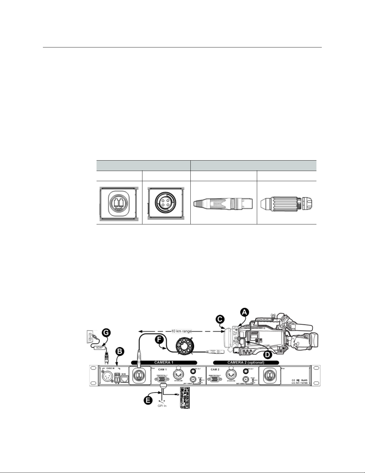
When connected directly to a Base Station using tactical fiber, the system is typically
configured as shown in Figure 2-1, and uses the following components:
• A: Camera Unit
• B: DC-powered Base Station
• C: Battery or Local Power Source
• D: CHCR camera remote cable
• E: CHBR base remote cable
• F: Hybrid fiber optic cable
• G: ADAP 12VDC Power Supply
Fig. 2-1: Direct Connect to Base Station with Power Wafer
6
Page 13
CopperHead Pro
User Guide
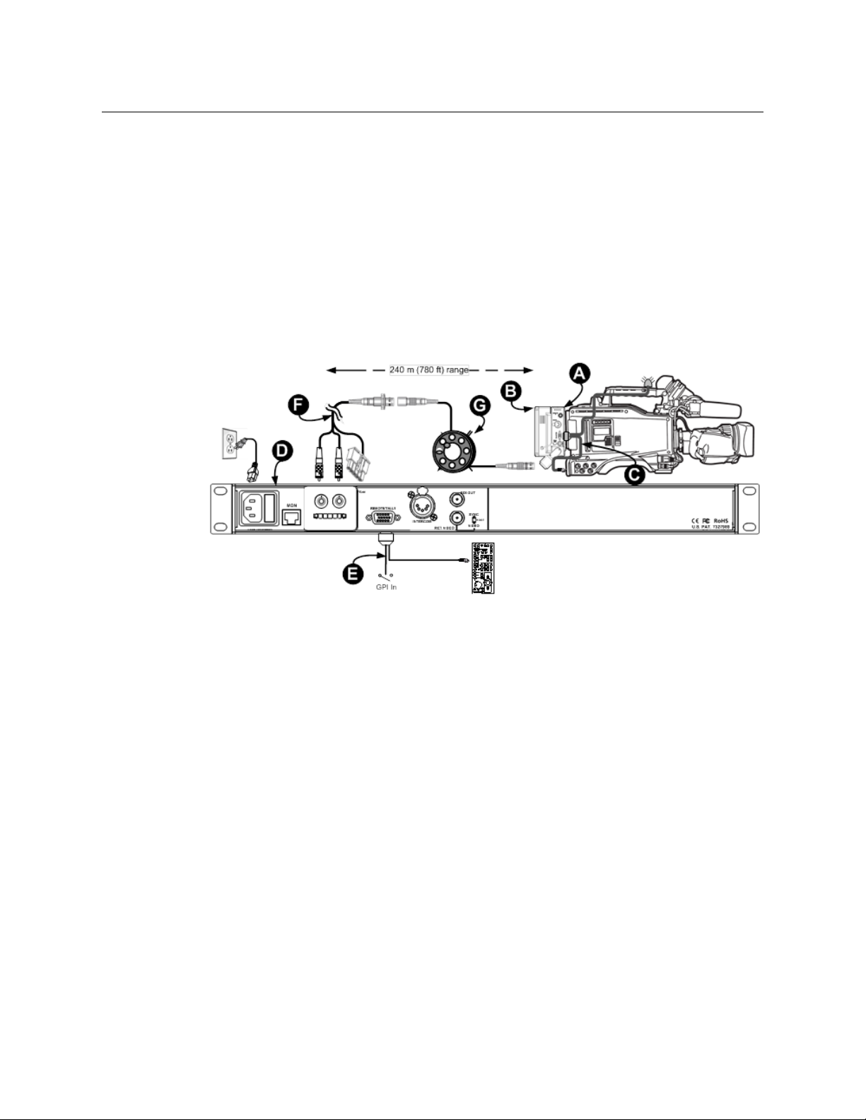
Power Wafer, Remote Panel-Mounted Fiber Connector
The hybrid fiber receptacle may be mounted a distance from the Base Station if the station
is equipped with a pair of inexpensive ST fiber connectors and a Molex receptacle to carry
power (Figure 2-2).You can use a breakout cable or infrastructure wiringto connect the
hybrid fiber receptacle to Base Station.
• A: Camera Unit
• B: Power Wafer
• C: CHCR camera remote cable
• D:
AC-powered Base Station with internal
camera power supply
Fig. 2-2: Powered Base Station with Fiber Receptacle Extension
• E: CHBR base remote cable
• F:
ST & Molex breakout cable or
campus/building infrastructure
• G: Hybrid fiber optic cable
7
Page 14
System Overview
Dry Fiber Systems - Locally powered cameras
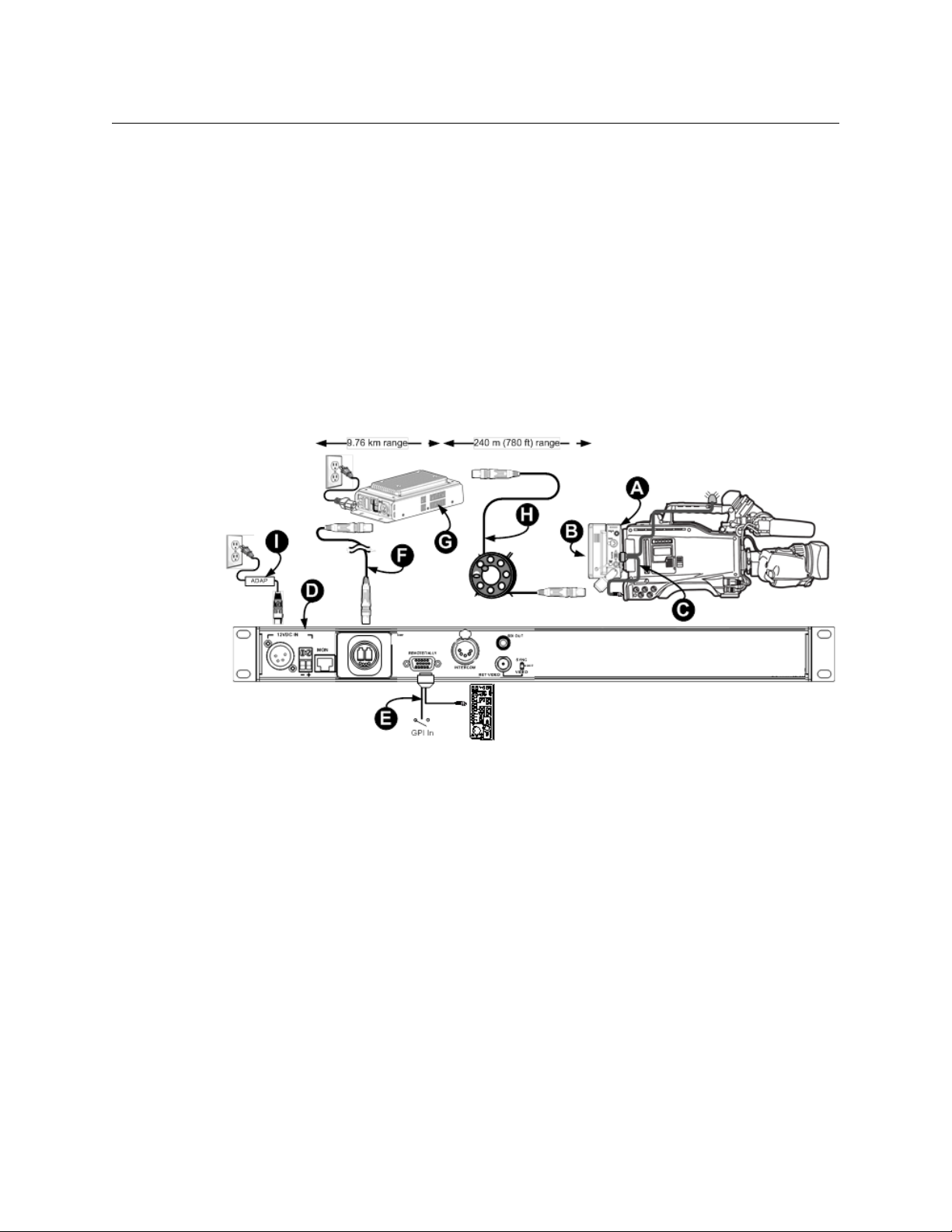
PowerWafer, with MPS Power Supply
Systems can be configured so that the majority of the fiber run is made via "dry" tactical or
infrastructure fiber, after which a "throwdown" MPS Power Supply is placed in line to
provide powered SMPTE hybrid fiber cable to the camera. In this configuration, as shown in
Figure 2-3, the Base Station can be separated from the MPS power supply by more than
nine kilometers (5.6 miles), where powered cable can be run to the camera for 240 meters
(780 feet), providing up to 95 watts of power to the camera and accessories.
• A: Camera Unit
• B: Power Wafer
• C: CHCR camera remote cable
• D:
DC-powered Base Station
• E: CHBR base remote cable
• F:
Tactical fiber or Infrastructure fiber run
• G: MPS Power Supply
• H: Hybrid fiber optic cable
• I: ADAP 12VDC power supply
Fig. 2-3: System using MPS Power Supply
8
Page 15
CopperHead Pro
User Guide
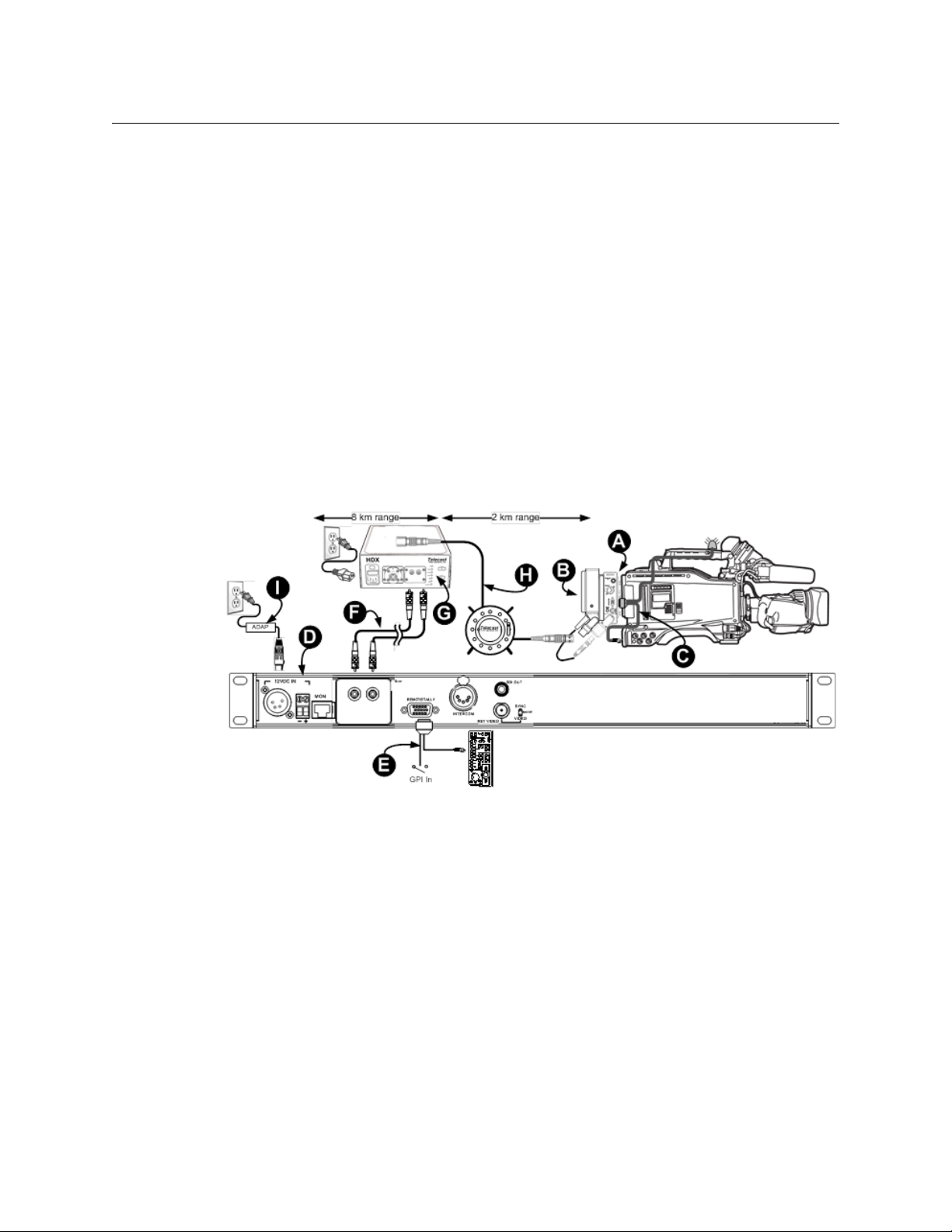
PowerPlus - High Power/Long Distance with HDX Power Supply
When power needs to be run for distances exceeding 240 meters or power requirements
exceed 95 watts for the camera and accessories, the external HDX power supply and
PowerPlus may be utilized. The PowerPlus can deliver up to 150 watts of power to the
camera and accessories.
The first part of the fiber run can be made via "dry" tactical or infrastructure fiber, after
which the HDX power supply is placed in line to provide powered SMPTE hybrid fiber cable
for the camera.
Such a system is typically configured as shown in Figure 2-4 and includes the following
components:
• A: Camera Unit
• B: PowerPlus
• C: CHCR camera remote cable
• D:
DC-powered Base Station
• E: CHBR base remote cable
Fig. 2-4: System using PowerPlus and HDX
• F:
Tactical fiber or Infrastructure fiber run
• G: HDX Power Supply
• H: SMPTE 311M hybrid fiber optic cable*
• I: ADAP 12VDC power supply
The Base Station can be separated from the MPS power supply on "dry fiber" (F ) by more
than nine kilometers (5.6 miles) , where powered hybrid cable (H) can be run to the camera
for another two kilometers (1.2 miles).
9
Page 16
System Overview
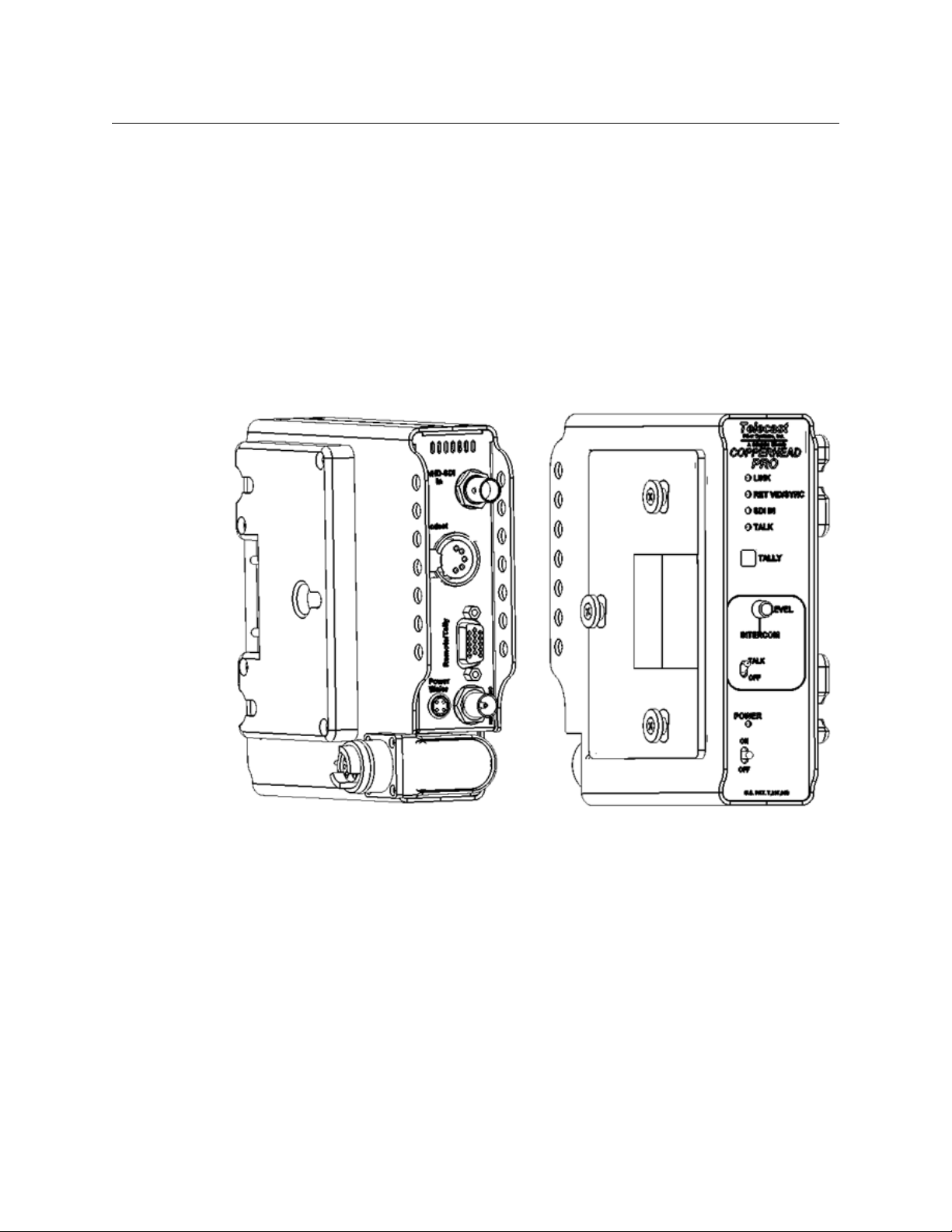
Camera Unit Front
(attaches to the camera)
Camera Unit Rear (attaches to
battery or power supply)
CopperHead Pro Transceiver System Components
CopperHead Pro Transceiver System Components
The CopperHead Pro Camera Unit fits between the battery or optional power supply and
the camera. The Camera Unit is configured at time of purchase with mounting plates to
accommodate the appropriate camera battery type.
The camera battery or optional power source attaches to Camera Unit, which in turn,
attaches to the video camera. Batteries accommodated are Anton/Bauer Gold Mount and
Sony "V" Mount. Other camera mounting plates may be available by special order. Contact
Grass Valley (see Contact Us on page 57) or your authorized dealer.
The Camera Unit is equipped with a swivel-mounted fiber optic connector, which can be
ordered with an OpticalCON, MX or SMPTE 304M connector. For more information, see
Parts & Accessories on page 75.
10
Fig. 2-5: Camera Unit Front and Rear
The actual appearance of your CopperHead Pro Camera Unit will vary depending on the
battery mount and fiber cable connector options specified at the time of purchase.
Page 17
Base Station Overview
The CopperHead Pro Base Station is a one rack-unit high device that provides all of the
inputs for signals going to the CopperHead Pro Camera Unit, as well as the outputs for the
signals coming from Camera Unit. Base Station is available in a variety of configurations.
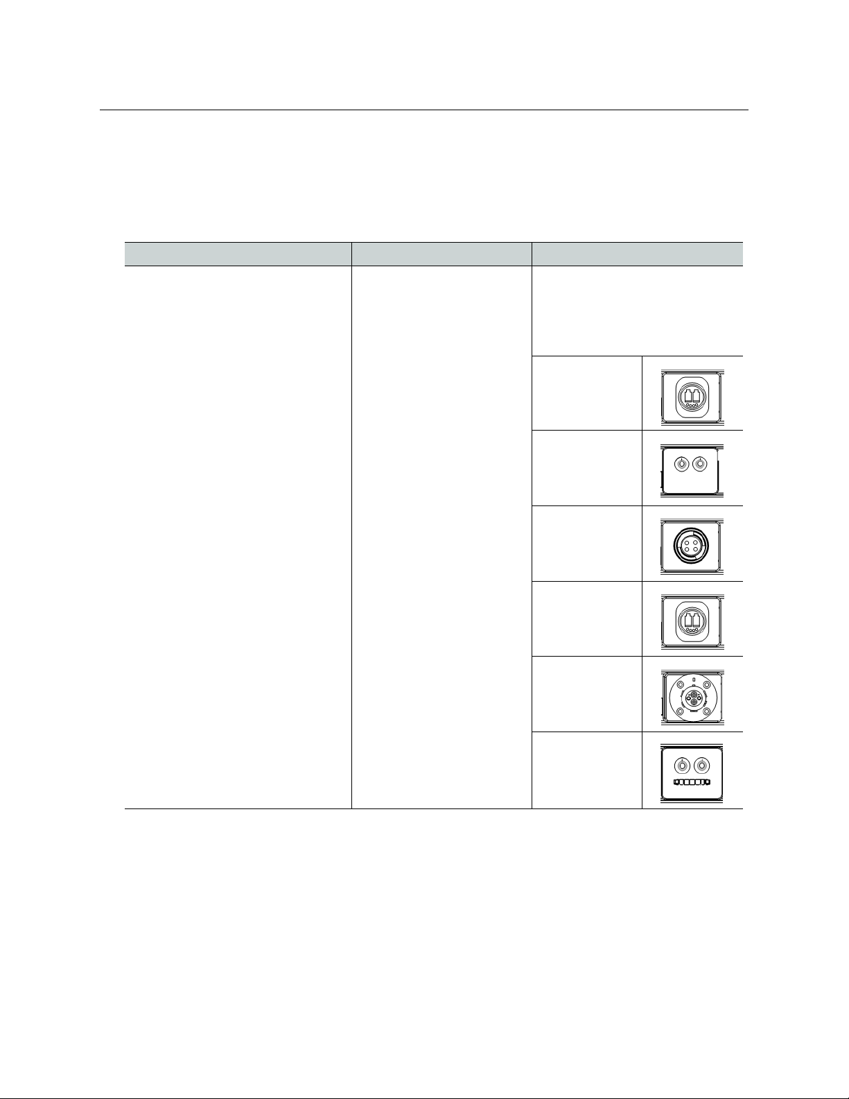
The options are:
Power Supply Single or Double Fiber Connector
12 Volt DC Input: “Dry Fiber”
• No Internal camera power supply
• Does not supply power to Camera
Unit via SMPTE hybrid fiber cable
• Is typically used with Tactical fiber
cable and/or infrastructure cabling
• Available in “Dual” configuration for
interface and control of two Camera
Units in a single one RU device
120/220 Volt AC Input – “Powered
Fiber”
• Includes internal power supply for
Camera Unit
• Supplies power to Camera Unit via
SMPTE hybrid fiber cable
•Not available in “Dual”
configuration. Can only interface
and control a single Camera Unit
Single Configuration
• Interface and control a
single Camera Unit
• Available in 12 Volt DC and
120/220 VAC models
Dual Configuration
• Interface and control two
Camera Units in a one RU
device
• Available in 12 Volt DC only.
• Not available for 120/220
VAC mod els
Six different fiber connectors are
available for the
Base Station (see Rear Panel
Section B - Optical Connector on
page 25 for details).
•OpticalCON
(dry)
•Two STs
• MX (Expanded
Beam)
CopperHead Pro
User Guide
CopperHead Pro
•OpticalCON
(powered)
• SMPTE 304M
•Two STs and
Molex
11
Page 18
System Overview
Types of Base Stations
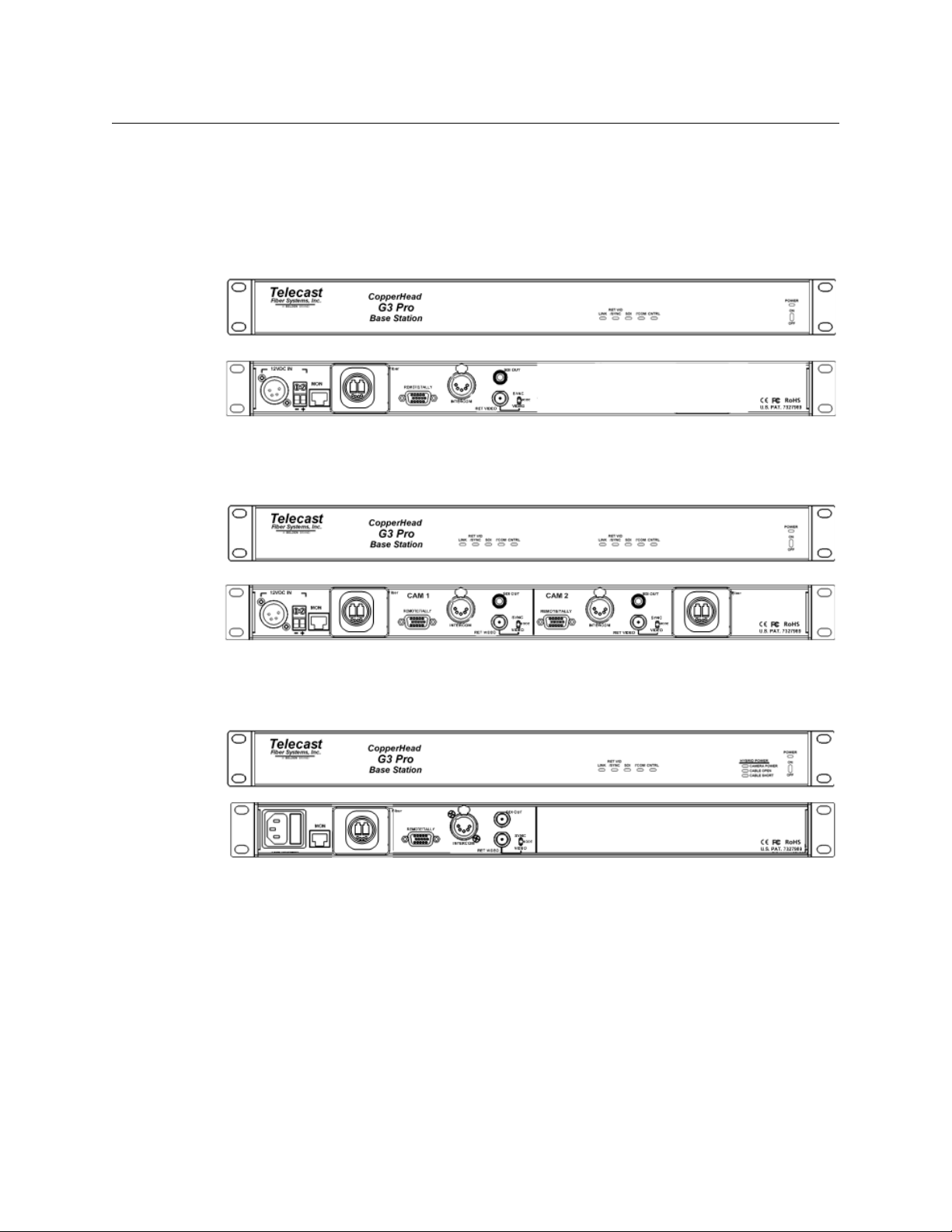
Types of Base Stations
The actual appearance of your CopperHead Pro Base Station will vary depending on the
fiber cable connectors and power option specified at the time of purchase.
Single “Dry” Station
Fig. 2-6: Single "Dry" Base Station - Front Panel (top) and Rear Panel (bottom)
Dual Unpowered Base Station
Fig. 2-7: Dual Unpowered Base Station - Front Panel (top) and Rear Panel (bottom)
Powered Base Station
Fig. 2-8: Powered Base Station - Front Panel (top) and Rear Panel (bottom)
12
Page 19

CopperHead System Components
This chapter provides descriptive information for the CopperHead Pro system components.
Camera Unit . . . . . . . . . . . . . . . . . . . . . . . . . . . . . . . . . . . . . . . . . . . . . . . . . . . . . . . . . . . . . . . . . . . . . . . . . 14
Base Station . . . . . . . . . . . . . . . . . . . . . . . . . . . . . . . . . . . . . . . . . . . . . . . . . . . . . . . . . . . . . . . . . . . . . . . . . . 21
PowerWafer Camera Adaptor . . . . . . . . . . . . . . . . . . . . . . . . . . . . . . . . . . . . . . . . . . . . . . . . . . . . . . . . . 27
MPS External PowerWafer Power Supply . . . . . . . . . . . . . . . . . . . . . . . . . . . . . . . . . . . . . . . . . . . . . . 28
PowerPlus 3000 - Camera Power Adaptor . . . . . . . . . . . . . . . . . . . . . . . . . . . . . . . . . . . . . . . . . . . . . 30
HDX Power Supply . . . . . . . . . . . . . . . . . . . . . . . . . . . . . . . . . . . . . . . . . . . . . . . . . . . . . . . . . . . . . . . . . . . 33
13
Page 20
CopperHead System Components
Camera Unit
Camera Unit
Camera Unit - Front Side
14
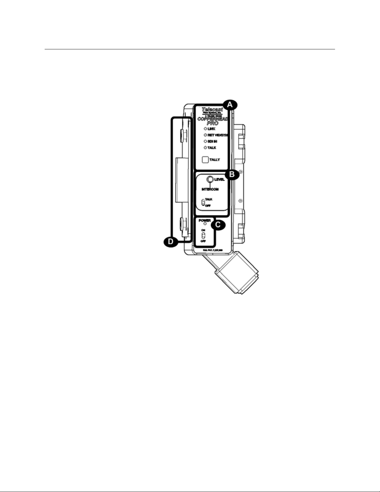
Fig. 3-1: Camera Unit - Front Side
The front of the CopperHead Pro Camera Unit has four features:
• A: Signal Status Panel: indicates the status of the various signals coming to and being
sent from the Camera Unit (see Camera Unit - Signal Status Panel (Section A) on
page 15).
• B: Intercom Controls: controls for intercom "talk" and "listen" functionality (see Camera
Unit - Intercom Controls (Section B) on page 16).
• C: Power Switch and Indicator: controls for power to the Camera Unit (see Camera Unit
- Power Switch & Indicator (Section C) on page 16).
• D: Camera Mounting Plate: mechanical mounting hardware for affixing CopperHead
Camera Unit to a camera or camcorder (see Camera Unit - Camera Mounting Plate
(Section D) on page 17).
Page 21
CopperHead Pro
User Guide
Camera Unit - Signal Status Panel (Section A)
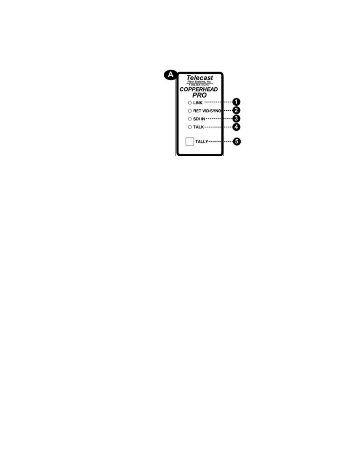
Fig. 3-2: Camera Unit Signal Status Indicators
• 1: Link: indicates the status of the data link from Base Station to Camera Unit. This is a
good indicator of a valid optical link.
• Green when Camera Unit has a data "lock" with Base Station.
• Red when Camera Unit is not "locked" to Base Station.
A data lock means that the fiber link is valid and data can be exchanged securely.
• 2: Return Video/Sync: indicates the presence of the composite video signal (VBS) sent
from Base Station to Camera Unit. This VBS can be used for return "program" video or
for genlock to the camera.
• 3: SDI in: Green indicates the presence of digital SDI video at Camera Unit's input BNC.
• 4: Talk: lights Green to indicate that the intercom Tal k switch (see Camera Unit -
Intercom Controls (Section B) on page 16) is in the Ta lk position, and that the headset
mic is open.
• 5: Tally: lights Red when GPI/Tally signal is activated at Base Stations
For suggestions on connecting Tally in your system, see Connecting Base Station to
Studio Infrastructure on page 42.
15
Page 22
CopperHead System Components
Camera Unit - Front Side
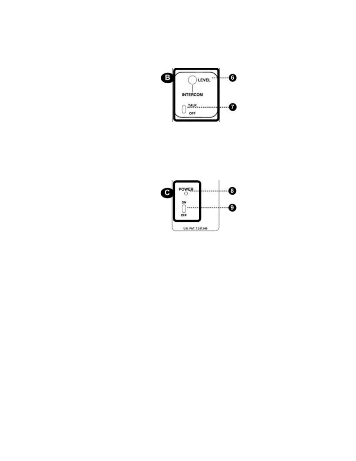
Camera Unit - Intercom Controls (Section B)
• Headset Level Knob: controls the volume of the intercom channel in the headset
•Intercom Talk Switch
• TA LK (up) opens the headset mic
• OFF (down) closes the headset mic
Camera Unit - Power Switch & Indicator (Section C)
• Power Indicator: lights Green to indicate main power is on
• Power On/Off: turns the main power supply on and off
16
Page 23
CopperHead Pro
Anton Bauer Camera
Mounting Plate
V-Mou nt Came ra
Mounting Plate
User Guide
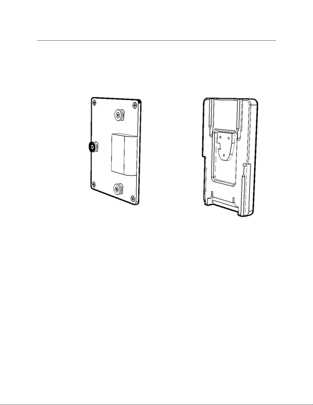
Camera Unit - Camera Mounting Plate (Section D)
This plate is used to mount the CopperHead Pro Camera Unit to a camera or camcorder.
Camera Unit is typically shipped with an Anton/Bauer "Gold Mount" or Sony-style "VMount" camera mounting plate. Other camera mounting plates may be available by
special order. Formore information, contact Grass Valley (see Contact Us on page 57) or
your authorized dealer.
Fig. 3-3: Camera Unit: Camera-side mounting plates
17
Page 24
CopperHead System Components
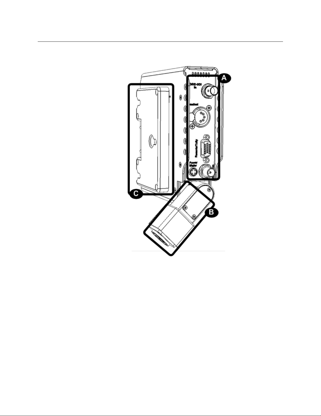
Camera Unit - Rear Side
Camera Unit - Rear Side
18
Fig. 3-4: Camera Unit Back Side
The back side of Camera Unit has three features:
• A: Connector Panel (see Camera Unit - Connectors (Section A) on page 19)
• B: Fiber Connector/Swivel (see Camera Unit - Fiber Connector/Swivel (Section B) on
page 20)
• C: Battery Mount (see Camera Unit - Battery Mount (Section C) on page 20)
Page 25
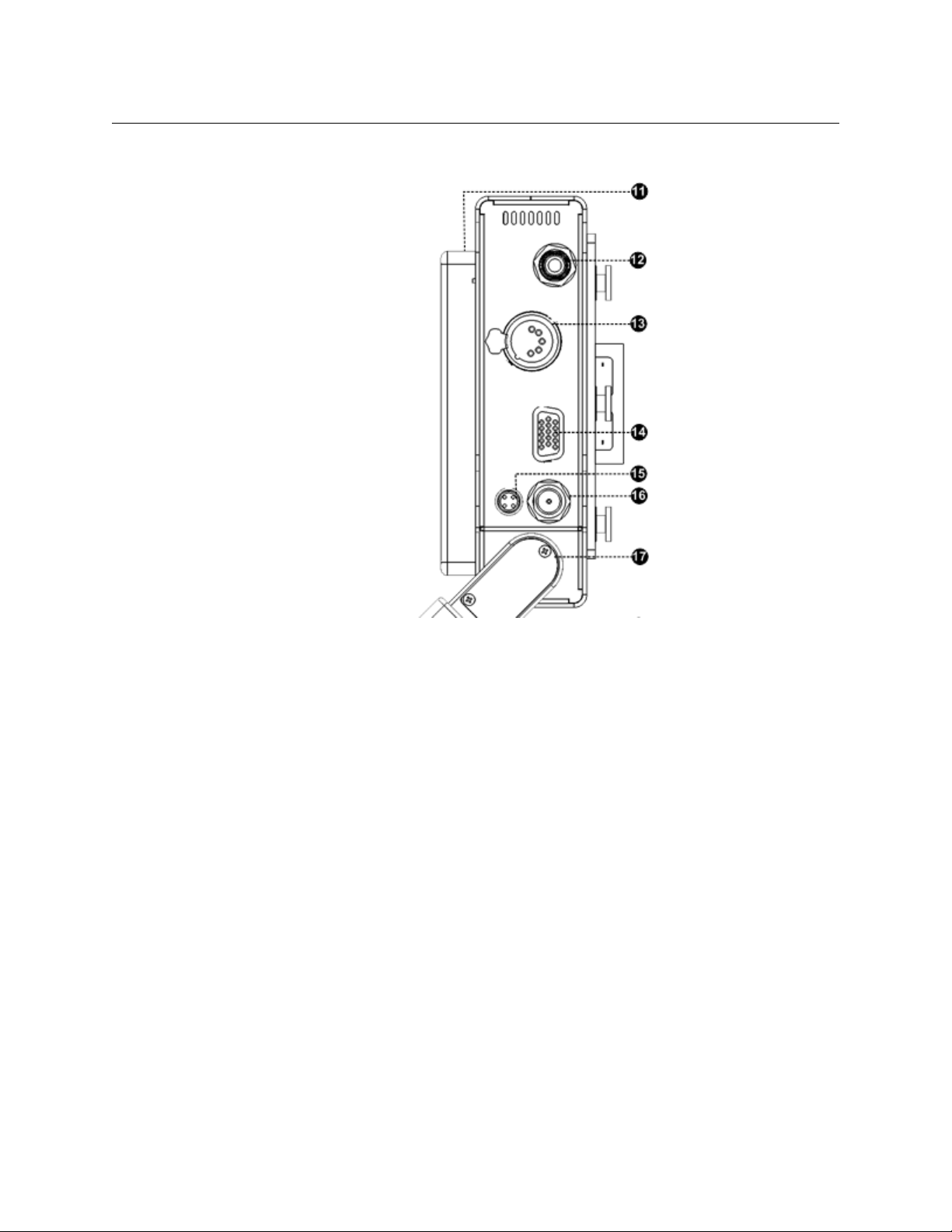
Camera Unit - Connectors (Section A)
CopperHead Pro
User Guide
Fig. 3-5: Camera Unit Connectors
• 11: Battery Mounting Plate: typically equipped for with Anton/Bauer or V-Mount
batteries
• 12: SD/SDI or HD/SDI Input - to Base Station: digital video input connector from
camera's SDI output
• 13: Intercom Headset Jack: connect 5-pin XLR Male intercom headset connector
• 14: Connector for CHCR cable: Camera Remote Control, Tally: DB15HD connector for
Camera Remote Control, Tally input and output. See Camera Unit & Base Station
Interface Cables on page 73 for the correct cable for your camera.
• 15: PowerWafer Connector: for use with PowerWafer when used with the AC-powered
Base Station or the MPS power supply. Connect with CH3CP-INF-2FAG cable.
• 16: VBS (analog composite video) or Genlock Out - from Base Station: connect to
camera's Genlock/Sync input connector or to external VBS monitor
• 17: Fiber Connector Swivel: attach fiber cable to connector mounted here.
19
Page 26
CopperHead System Components
Anton Bauer Battery
Mounting Plate
V-Mount Battery
Mounting Plate
Camera Unit - Rear Side
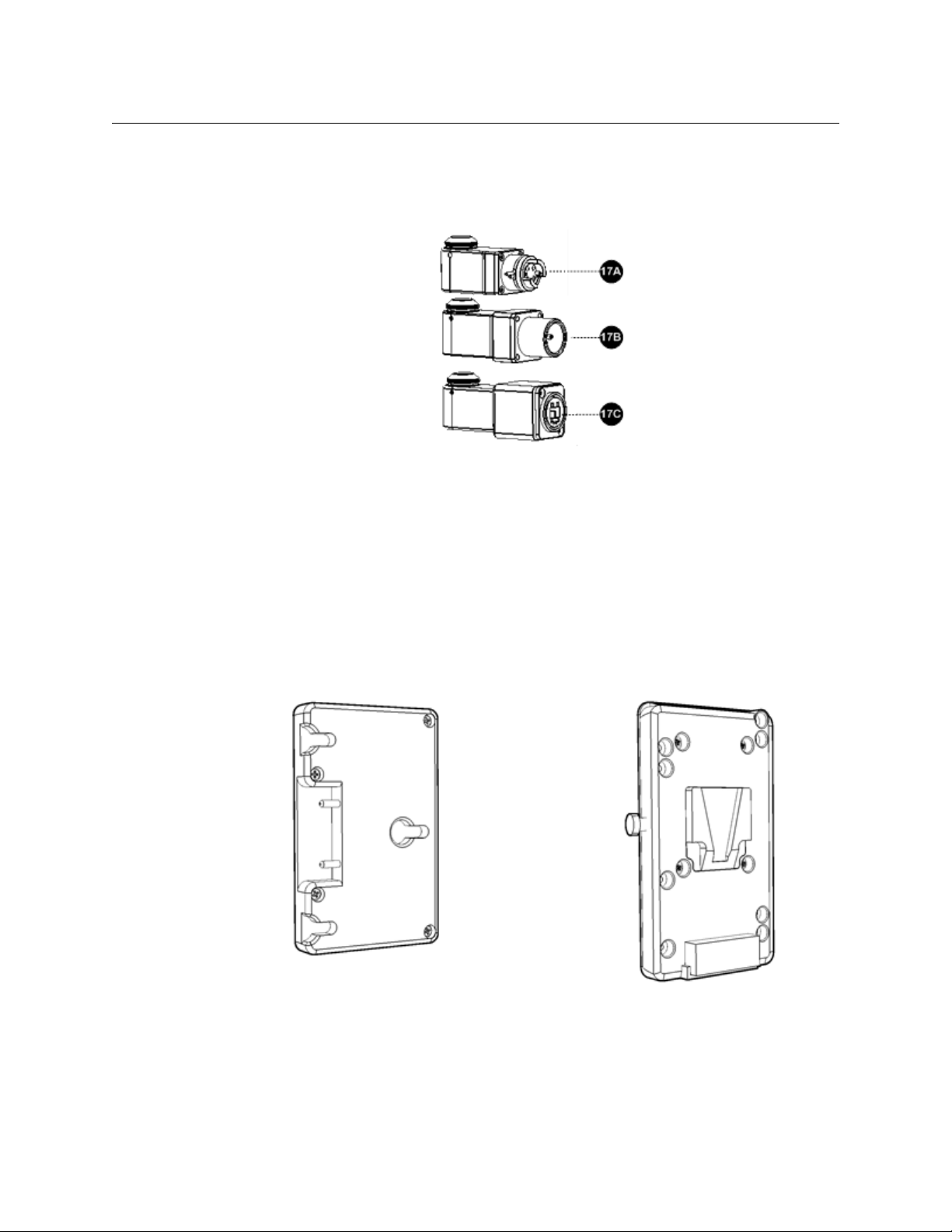
Camera Unit - Fiber Connector/Swivel (Section B)
The CopperHead Pro Camera Unit is typically equipped with one of the three fiber
connectors shown in Figure 3-6:
• 17A: MX Expanded Beam (unpowered)
• 17B: SMPTE 304M (powered)
• 17C: OpticalCON (powered or unpowered)
Fig. 3-6: Camera Unit Fiber Connectors
Camera Unit - Battery Mount (Section C)
The CopperHead Pro Camera Unit can be shipped with a variety of plates to attach the unit
to your camera. The Anton Bauer mount and the "V"-mount are the most common,
although PAG and other battery mount systems are also available by special order. Formore
information, contact Grass Valley (see Contact Us on page 57) or your authorized dealer.
Fig. 3-7: Camera Unit - Battery side mounting plates
20
Page 27
Base Station
The CopperHead Base Station is available with a number of options. The unit is ordered
with a specified Power Module, Audio/Intercom Module, and Fiber Connector. For an
overall view of component location,see Overview Diagrams on page 78.
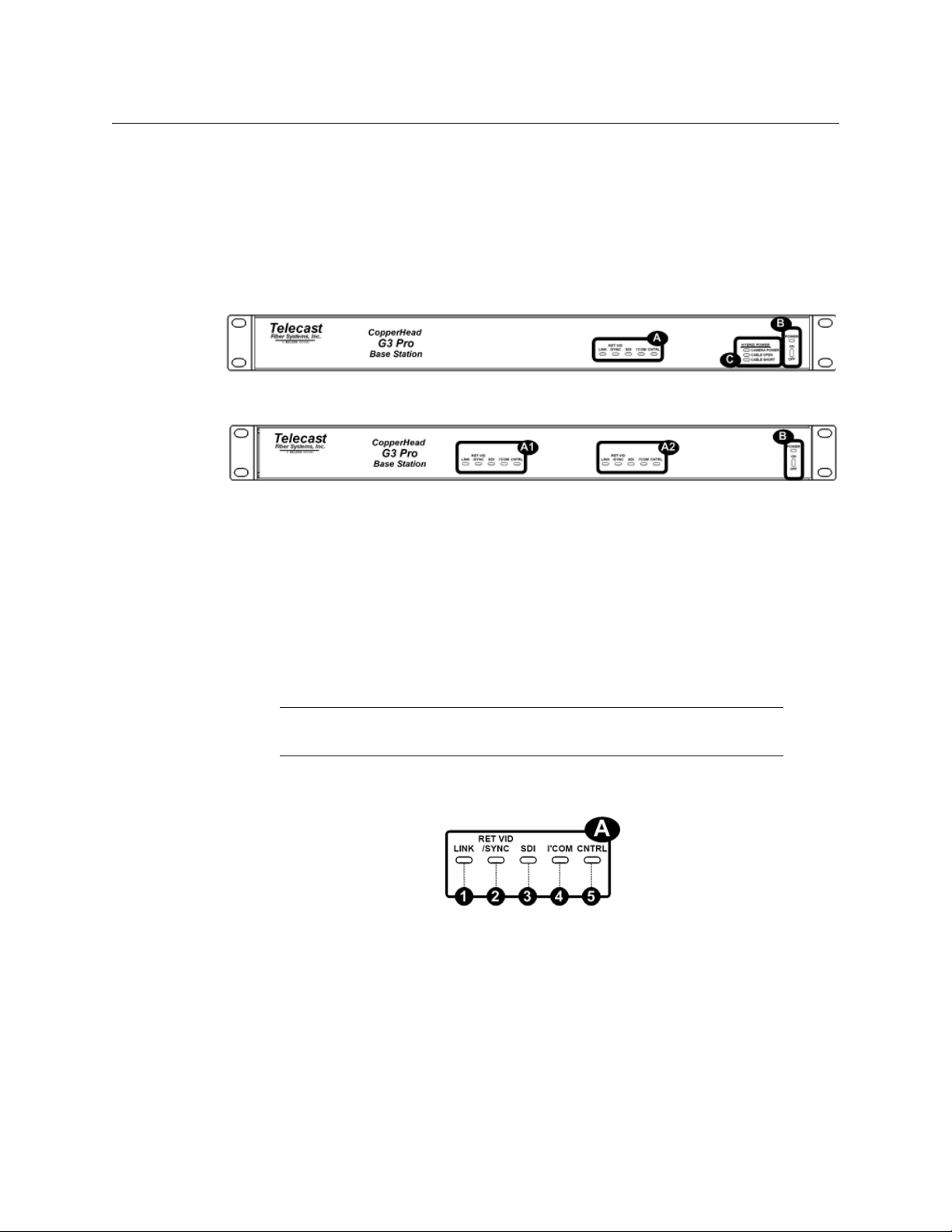
Base Station Front Panel
Fig. 3-8: Base Station Front Panel - single unit, 120/220 VAC power w/internal hybrid power supply
CopperHead Pro
User Guide
Fig. 3-9: Base Station Front Panel - dual unit, 12 VDC power
The front of Base Station has three features:
• A: Signal Status Indicators (see Front Panel Section A - Signal Status Indicators on
page 21)
Applies if Dual Base Station, A1 and A2. Otherwise, only A2 applies.
• B: Power Switch and Indicator (see Front Panel Section B- Power Switch and Indicator
on page 22)
• C: Hybrid Power Status Indicators (see Front Panel Section C- Hybrid Power Status
Indicators on page 23)
Note: These indicators only appears on Base Stations equipped with
internal hybrid power supply.
Front Panel Section A - Signal Status Indicators
Fig. 3-10: Base Station Status Indicators
• 1: Link: indicates the status of the data link from Camera Unit to Base Station. This is a
good indicator of adequate optical link.
• Green when Base Station has a data "lock" with Camera Unit.
• Red when Base Station is not "locked" to Camera Unit.
A data lock means that the fiber link is valid and data can be exchanged securely.
21
Page 28

CopperHead System Components
Base Station Front Panel
• 2: Return Video/Sync: indicates the presence of the analog video signal (VBS) at Base
Station's VBS In BNC. This VBS can be used for return "program" video or for genlock to
the camera.
• 3: SDI Presence: lights Green to indicate the presence of digital SDI video from Camera
Unit. This LED stays illuminated Green as long as the Base Station is receiving adequate
optical power. See A Brief Guide to Measurement of Fiber Optic Signal Strength on
page 61 for more information.
• 4: Intercom: lights Green to indicate audio activity on the Intercom channel.
• 5: Control: lights Green when camera control data is being transmitted between
Camera Unit and Base Station.
Front Panel Section B- Power Switch and Indicator
Fig. 3-11: Base Station Power Switch
• 6: Power: indicates that power is applied to Base Station.
• Green when Base Station is fully powered
• Red when there is power connected to Base Station, but Base Station is not turned
on
• 7: Power Switch: switchesthe Base Station on or off. With a hybrid power system
(power supplied by Base Station), this switch controls power to the camera and Camera
Unit.
22
Page 29

CopperHead Pro
User Guide
Front Panel Section C- Hybrid Power Status Indicators
This section is optional, and only appears on CopperHead Base Stations equipped with
internal power supplies designed to work with a CopperHead Camera Unit connected to a
PowerWafer.
Fig. 3-12: Base Station Hybrid Power Status Indicators
• 8: Camera Power: lights Green when high voltage is being supplied to Camera Unit.
• 9: Cable Open: lights Red when the SMPTE hybrid cable is open or when there is no
SMPTE hybrid cable connected.
High voltage will not be applied to the hybrid connector until the open condition is
corrected.
• 10: Cable Short: lights Red when the SMPTE hybrid cable has a short circuit in it.
High voltage will not be applied to the hybrid connector until the short-circuit is
corrected or the cable is replaced.
23
Page 30

CopperHead System Components
Base Station Rear Panel
Base Station Rear Panel
Fig. 3-13: CopperHead Pro Base Station Back Panel (Dual model shown)
• A: Power Connector (see Rear Panel Section A - Power Connector on page 24)
• B: Fiber Connectors (see Rear Panel Section B - Optical Connector on page 25 )
• C: Signal Connectors (see Rear Panel Section C - Signal Connectors on page 26)
Rear Panel Section A - Power Connector
The CopperHead Base Station can be configured for DC or AC power.
12VDC Power Interface
This power interface is used on CopperHead Base Stations that are not equipped with
internal power supplies. This type of Base Station is typically used with Camera Units
powered locally with a battery or a local power supply at the camera.
Fig. 3-14: 12VDC Power Connector
• 11: 12V DC Power input connector (XLR 4 Pin)
• 12: 12V DC Input - terminal block: can be used in lieu of the 4-pin XLR or in parallel as a
redundant input. See Base Station Connectors on page 65 for pin-out details.
• 13: For Future Use (RJ45)
24
Page 31

CopperHead Pro
User Guide
AC Power Connector Interface
This power interface is used on CopperHead Base Stations that are equipped with an
internal power supply. This type of Base Station is typically used with Camera Units
powered with a PowerWafer via SMPTE Hybrid cable
Fig. 3-15: AC Mains Connector
• 20: AC Power Receptacle 100-240V 50/60 Hz
• 21: 3.15 amp dual fuse assembly (see Base Station Connectors on page 65 for fuse
specification)
• 13: For Future Use (RJ45)
Rear Panel Section B - Optical Connector
The fiber optic connector is used to connect Base Station directly to Camera Unit or to the
external MPS or HDX power supply configured with your system. The type of fiber
connector will vary depending on your system configuration.
Six types of fiber optic connectors are available for use with the CopperHead Base Station.
"Dry" (unpowered) fiber connectors Fiber Connectors with Copper for Power
A: OpticalCON
(dry)
B: STs C: MX D: OpticalCON
(powered)
E. SMPTE 304M F. STs & Molex
25
Page 32

CopperHead System Components
Base Station Rear Panel
Rear Panel Section C - Signal Connectors
• 5: Connector for Camera Remote Control Panel and Tally input (DB15HD): connect
CHBR-PRO cable here, specified for your particular Camera Remote Control Panel.
See CHBR-PRO Base Station Remote Cable on page 74 to specify the correct cable for
your Camera Remote Control Panel.
• 6: Base Station Intercom Connector: connect your house intercom system here:
• XLR3: Two-wire (Clear-Com or RTS)
• XLR5M: Four-wire (matrix-style)
For more information, refer to Intercom connectivity on page 43.
• 7: SD/SDI or HD/SDI Output: digital video from camera's SDI output
• 8: VBS Return Input: analog composite video signal sent to Camera Unit
• 9: VBS Return Input Switch: switches the VBS Return Input connector to be optimized
for one of two uses:
• A: Sync In: Genlock/Sync/Tri-Level sync signal.
• B: Composite Video In: typically used to send analog VBS return video to the
camera or an external monitor.
Fig. 3-16: Rear Panel Signal Connectors
26
Page 33

PowerWafer Camera Adaptor
The CopperHead Camera Unit can be powered by the optional "PowerWafer" Camera
Adaptor. The PowerWafer replaces the local camera battery and any local AC power supply
adaptor. The PowerWafer gets its power from the use hybrid fiber cable and the
CopperHead Base Station equipped with the internal power supply or from the MPS
external power supply.
You can deliver up to 95 watts of power to the camera, Camera Unit, and camera-powered
accessories. You can use up to 780 feet (240 meters) of cable when the Camera Unit is
powered directly from Base Station.
The use of an external power supply can extend Base Station to Camera range and increase
camera power flexibility. The MPS Throw Down device or Wafer Power Adaptor provides
this functionality. This unit is described in MPS External PowerWafer Power Supply on
page 28.
The PowerWafer replaces the battery or local battery mountable AC adaptor (shown with
the Anton/Bauer "Gold Mount" option).
•1: Heat Sink
• 2: Battery Mounting Plate (Anton/Bauer Gold Mont or "V-Mount")
• 3: Power Input Connector
CopperHead Pro
User Guide
High voltage power is carried from Base Station to Camera Unit. A short jumper cable
(CH3CP-INF-2FAG) carries the high voltage power from Camera Unit to the PowerWafer's
power input connector (where it is converted to 12VDC power). The 12VDC power is
delivered back to the camera via the battery mounting plate.
Fig. 3-17: PowerWafer Power Adaptor and Jumper Cable
27
Page 34

CopperHead System Components
MPS External PowerWafer Power Supply
MPS External PowerWafer Power Supply
The CopperHead MPS external power supply provides 95 watts of 12VDC power and fiber
connectivity from Base Station to Camera Unit equipped with a CopperHead PowerWafer.
Connectivity between the MPS unit to the camera can be configured using either a Hybrid
OpticalCON connector or a SMPTE 304M connector. The nominal distance between them is
240 meters (780 feet).
Connectivity between the MPS unit and Base Station uses "dry" fiber and can be configured
with a "dry" OpticalCON connector or two ST connectors. The MPS is powered locally with
standard AC power. The unit is free-standing (see Hybrid Fiber Cable between MPS Power
Unit and Camera Unit on page 46 for system configuration with the MPS Power Supply and
PowerWafer).
28
Fig. 3-18: MPS Power Supply, Front and Rear
• 1: AC Power Receptacle: 100-240V 50/60 Hz
• 2: Fuse compartment: see AC Power Input Connector- Models CHG3-BS-Pro-95VD-xxx-
xxx on page 65 for the fuse specification.
• 3: Power Switch
• 4: For Future Use (RJ45)
• 5: "Dry" Fiber Optic Connection to CopperHead Base Station: this removable plate
can be equipped with two ST connectors or a "dry" OpticalCON connector (see
Figure 3-19).
•6: Heat Sink
• 7: Powered Fiber Optic Connection to CopperHead Camera Unit: this removable
plate can be equipped with a SMPTE 304M connector or a powered OpticalCON
connector. See Figure 3-20.
Page 35

CopperHead Pro
User Guide
Fig. 3-19: MPS "dry" fiber connector options
The "dry" connection (#5 in Figure 3-18)to the CopperHead Base Station can be equipped
with two ST connectors or a "dry" OpticalCON connector.
Fig. 3-20: MPS powered fiber connector options
The powered connection (#7 in Figure 3-18) to the CopperHead Camera Unit can be
equipped with a SMPTE 304M connector or a powered OpticalCON connector.
Dry Unpowered Fiber
Connection to Base Station
Part Number
CH2-MPS-95VD-2ST-NEU 2 STs OpticalCON
CH2-MPS-95VD-2ST-304 2 STs SMPTE 304M
CH2-MPS-95VD-NEU-NEU OpticalCON OpticalCON
CH2-MPS-95VD-NEU-304 OpticalCON SMPTE 304
(#5 in Figure 3-18)
Powered Fiber Connection
to Camera
(#7 in Figure 3-18)
29
Page 36

CopperHead System Components
High Profile
Heat Sink
Low Profile
Heat Sink
PowerPlus 3000 - Camera Power Adaptor
PowerPlus 3000 - Camera Power Adaptor
The standard CopperHead PowerPlus 3000 power adaptor with standard (Low Profile) heat
sink (Figure 3-21) provides 100 watts of 12VDC power and fiber cable signal connectivity
from Base Station to the Camera. It also provides an external power feed of 12VDC and
optionally 24VDC for external accessories. The PowerPlus unit requires the use of the HDX
power supply.
The PowerPlus can be equipped with a "High Profile" heat sink (Figure 3-21) for power
requirements up to 150 Watts.
The PowerPlus unit is equipped with a fixed tactical fiber "dongle" that can be terminated
with either an OpticalCON plug, SMPTE 304M plug, or an MX plug. This dongle plugs into
the swivel of the CopperHead Camera Unit.
The PowerPlus is connected to the HDX power supply using Hybrid fiber cable with SMPTE
304 connectors. See Mounting the CopperHead Pro Camera Unit with the PowerPlus on
page 38 for details on connecting the PowerPlus.
The distance between the HDX power adaptor and the camera can be up to 2km (1.2 miles)
using Hybrid fiber cable and the distance between the HDX power adaptor and Base
Station can be up to 7km (4.3 miles).
Fig. 3-21: PowerPlus 3000 with Low and High Profile Heat Sink mounted to CopperHead Pro
30
Page 37

CopperHead Pro
User Guide
Fig. 3-22: PowerPlus 3000 LED Indicators
• 1: +24 Volt DC "A": lights up when 24 Volts is available on connector X
• 2: Power In: indicates that power is being received from the HDX power supply
• Red - initial safety handshaking in progress, full power not engaged.
• Green - safety handshaking completed, full power being received from HDX power
supply.
• 3: Camera Out: indicates that 12VDC is being supplied to the battery plate
• 4: Auxilliary +12 Volt Output: indicates 12 Volt is being supplied to the 4-pin XLR
connector(#7 on Figure 3-23)
• 5: +24 Volt DC "B": lights up when 24 Volts is available on connector(#10 on Figure 3-
23)
• 6: Battery Plate: used to mount the PowerPlus to the CopperHead Camera Unit
(Anton/Bauer or V-Mount)
31
Page 38

CopperHead System Components
PowerPlus 3000 - Camera Power Adaptor
Fig. 3-23: PowerPlus 3000 Connectors
•7: Heat Sink
• LP- Low Profile Heat Sink rated for 100 Watts (shown)
• HP - High Profile Heat Sink rated for 150 Watts
• 8: 12 Volt Auxiliary Output: 4-Pin XLR output connector for 12 Volt accessories
• 9: 24 Volt Auxiliary Output B: 3-pin connector for 24 Volt accessories.
• 10: 24 Volt Auxiliary Output A: 3-pin connector for 24 Volt accessories.
• 11: Tactical Fiber Dongle: fixed tactical fiber cable connects to the CopperHead
Camera Unit.
• 12: SMPTE Swivel: adjustable swivel for SMPTE 304M receptacle am.
• 13: SMPTE 304M Hybrid Fiber Receptacle: connect the SMPTE hybrid cable here. This
cable connects to the PowerPlus.
• 14: Tactical Fiber Connector (MX shown): dry fiber connector at the end of the
dongle. This should match the connector on the swivel of the mating CopperHead
Camera Unit. Available with the following termination:
• MX plug (shown)
• OpticalCON Connector ("dry")
• SMPTE 304M plug ("dry")
32
Page 39

HDX Power Supply
The HDX Power Supply Unit is required when using the PowerPlus Camera Adaptor. The
HDX can be used as a free-standing unit or rack mounted, using the HDX-FR-2 for mounting
two HDX units.
The unit sends power via a SMPTE hybrid fiber cable to the PowerPlus, where it is converted
to 12VDC and optionally to 24VDC). For details on connecting the HDX to a CopperHead
system, see @PowerPlus - High Power/Long Distance with HDX Power Supply on page 9 .
CopperHead Pro
User Guide
Fig. 3-24: HDX device setups
The HDX has five features:
• A: AC Power Input Module and Switch: power switch and connector for AC Mains
• B: "Wet" SMPTE 304M Hybrid Fiber Connector: the SMPTE hybrid cable is connected
here. This cable connects to the PowerPlus at the camera. This mating connector pair
always uses SMPTE 304M connectors.
• C: "Dry" Fiber connector(s): connect the CopperHead Base Station. This interface can
be equipped with a variety of fiber connectors:
• Two ST connectors
• MX connector
• OpticalCON connector
• D: Status Indicators: these indicators show the status of the HDX's power system (see
HDX Status Indicators on page 34 for more details)
• E: HDX Integrated Handle: stand-alone unit can be carried or hung from this robust
handle
33
Page 40

CopperHead System Components
HDX Status Indicators
HDX Status Indicators
Fig. 3-25: HDX Displays
• 1: AC IN - MAINS: AC Input power is present
• 2: DC HV ENABLE: DC "Sense" voltage from PowerPlus is present
• 3: AC HV ENABLE: AC "Sense" voltage from PowerPlus is present
• 4: HV Present: AC or DC voltage is available on Hybrid connector
• 5: CABLE OPEN: no camera cable connected
• 6: CABLE SHORT: camera cable non-functional due to a short
• 7: REMOTE PWR ENABLE
• Red: if local/remote sw in remote position and opt power <= -27 dBm
• Green: if local/remote sw in remote position and opt power >= -24 dBm gates HV
power
• 8: LOAD TYPE: indicates the type of load or camera being used:
• N/A - No load detected
• PWR+ - PowerPlus detected
• 9: Optical Power: not used with PowerPlus.
• 10: Local Remote: not Used With PowerPlus.
34
Page 41

Camera Unit and Power Supply Installation
This chapter explains how to install the Camera Unit and Power Supply components.
Mounting the Copperhead Camera Unit with the PowerWafer . . . . . . . . . . . . . . . . . . . . . . . . 36
Connecting the CopperHead Pro System . . . . . . . . . . . . . . . . . . . . . . . . . . . . . . . . . . . . . . . . . . . . . . 40
Deployment of the CopperHead System . . . . . . . . . . . . . . . . . . . . . . . . . . . . . . . . . . . . . . . . . . . . . . 49
Insuring a Positive Fiber Link . . . . . . . . . . . . . . . . . . . . . . . . . . . . . . . . . . . . . . . . . . . . . . . . . . . . . . . . . . 49
Intercom Operation . . . . . . . . . . . . . . . . . . . . . . . . . . . . . . . . . . . . . . . . . . . . . . . . . . . . . . . . . . . . . . . . . . 50
Shutting Down the System . . . . . . . . . . . . . . . . . . . . . . . . . . . . . . . . . . . . . . . . . . . . . . . . . . . . . . . . . . . 51
Troubleshooting . . . . . . . . . . . . . . . . . . . . . . . . . . . . . . . . . . . . . . . . . . . . . . . . . . . . . . . . . . . . . . . . . . . . . 52
35
Page 42

Camera Unit and Power Supply Installation
Mounting the Copperhead Camera Unit with the PowerWafer
Mounting the Copperhead Camera Unit with the PowerWafer
When mounting the CopperHead Camera Unit, always position the camera so that the
battery mounting plate at the rear of the camera is easy to access. Ensure that the camera is
well-supported and stable. If a battery is mounted remove it and put it to one side.
Installing the CopperHead Camera Unit typically involves one of the following three
configurations.
• CopperHead Pro Camera Unit with a battery (see Mounting the CopperHead Pro
Camera Unit with a battery on page 36)
• CopperHead Pro Camera Unit with the PowerWafer (see Mounting the CopperHead Pro
Camera Unit with the PowerWafer on page 37)
• CopperHead Pro Camera Unit with the PowerPlus (see Mounting the CopperHead Pro
Camera Unit with the PowerPlus on page 38)
Mounting the CopperHead Pro Camera Unit with a battery
When the camera is powered locally at the camera position, either by a battery (as shown)
or by a local power source, tactical fiber is typically the preferred connection to Base
Station.
36
Fig. 4-1: Mounting the CopperHead Pro Camera Unit to the Camera
1 Attach the CopperHead Pro Camera Unit A to the camera battery mounting plate B. The
mounting is mechanically identical to attaching a battery.
2 Mount the battery C to the CopperHead Pro Camera Unit battery mounting plate D
exactly as you would mount the battery to the camera.
3 Instructions for attaching the required cables between the camera and Camera Unit
can be found in Connecting Camera Unit to a Camera or Camcorder on page 40 .
Page 43

Mounting the CopperHead Pro Camera Unit with the PowerWafer
The PowerWafer allows the camera and Camera Unit to be powered via hybrid fiber cable,
which is powered from the CopperHead Pro Base Station or MPS External Power Supply.
CopperHead Pro
User Guide
Fig. 4-2: Mounting the PowerWafer Unit to the CopperHead Pro Camera Unit
Fig. 4-3: Attaching the PowerWafer Cable
1 Attach the CopperHead Pro Camera Unit A to the camera battery mounting plate B.
The mounting is mechanically identical to attaching a battery. Instructions for
attaching the required cables between the camera and the Pro Camera Unit can be
found in Connecting Camera Unit to a Camera or Camcorder on page 40.
37
Page 44

Camera Unit and Power Supply Installation
Mounting the CopperHead Pro Camera Unit with the PowerPlus
2Mount the PowerWafer C to the CopperHead Pro Camera Unit battery mounting plate
D exactly as you would mount the battery to the camera.
3 Connect the supplied PowerWafer connector cable E. (model CH3CP-INF-FAG2)
between the PowerWafer C and the PowerWafer connector on Camera Unit A.
4 For best results, plug the straight connector F into the PowerWafer and the connector
with the Right Angle G into the Copperhead Camera Unit.
Mounting the CopperHead Pro Camera Unit with the PowerPlus
The PowerPlus allows the camera and Camera Unit to be powered via hybrid fiber cable for
extra-long distances at higher power than the PowerWafer. The PowerPlus is powered via
the hybrid fiber cable from the HDX Power Supply.
38
Fig. 4-4: Mounting the PowerPlus Unit to the CopperHead Pro Camera Unit
Fig. 4-5: PowerPlus on CopperHead Pro
Page 45

CopperHead Pro
User Guide
1 Attach the CopperHead Pro Camera Unit A to the camera's battery mounting plate B.
The mounting is mechanically identical to attaching a battery to the camera.
2 Mount the PowerPlus C to the CopperHead Pro Camera Unit battery mounting plate D
exactly as you would mount a battery to the camera.
3 Connect the PowerPlus "dongle" E to the fiber optic swivel F on Camera Unit A.
Connect the SMPTE hybrid cable connector G from the HDX to the SMPTE receptacle H
on the PowerPlus.
39
Page 46

Camera Unit and Power Supply Installation
Connecting the CopperHead Pro System
Connecting the CopperHead Pro System
The CopperHead Pro system is designed to integrate seamlessly into virtually any
production environment. Prior to connecting your system,ensure that each of the required
cables and accessories is available.
Connecting Camera Unit to a Camera or Camcorder
Fig. 4-6: Camera with CopperHead Pro and cables
Connecting the CopperHead Camera Unit requires the following:
• Two short BNC-terminated coax cables
•CHCS-Pro cable
• Headset
• External Tally light (optional)
•Fiber cable to Base Station
40
Page 47

CopperHead Pro
User Guide
Fig. 4-7: Camera Unit to Camera Connections
• 11: HD/SDI Input: connects to the camera's HD/SDI or SD/SDI output signal
• 12: Headset: receptacle for intercom headset
• 13: Remote/Tally: connect to CHCR-PRO cable. This cable connects to the Remote
connector of the camera, as well as to an external Tally light (customer supplied). See
Camera Unit on page 79 for details.
• 14: PowerWafer: connect to the PowerWafer using cable CH3CP-INF-2FAG. Powered
Base Station or MPS Power Supply required. See Parts & Accessories on page 75.
• 15: VBS Out: two options:
• Genlock: connect to the genlock input of your camera
• Return Video: connect to an external analog VBS monitor
• 16, 17: Fiber: swivel with fiber connector: MX, OpticalCON, or SMPTE 304M
41
Page 48

Camera Unit and Power Supply Installation
Connecting Base Station to Studio Infrastructure
Connecting Base Station to Studio Infrastructure
Connecting the CopperHead Base Station requires the following:
• Two BNC-terminated coax cables to connect to your infrastructure
•CHBR-Pro cable
•Camera Remote Panel
• XLR cable to connect to your intercom system (see Intercom connectivity on page 43)
• Access to your video switcher's tally outputs (optional)
• Fiber cable to Camera Unit
Fig. 4-8: CopperHead Pro Base Unit Connections
• 11: 12 VDC Input: connects to 12VDC power supply
• 20: 120/220 VAC Input: connects to AC mains
• 14: Fiber: connect fiber cable to CopperHead Camera Unit
• 15: Remote/Tally: connects to CHBS-PRO cable. This breakout cable connects to a
Camera Remote Control Panel. The pigtail connects to the tally output of a switcher or
to a studio Tally system. See CHBR-PRO Base Station Remote Cable on page 74 for
details.
• 16: Intercom: connects to the house intercom system is connected here (see Intercom
connectivity on page 43)
• 17: SDI Out: connects to the digital video output (HD/SDI-SDI) from your camera is
found here
• 18: Return Video In: connects to the house genlock/sync or return VBS analog video
• 19: Return Video Mode Switch: switches to optimize the return video path (18) for
Genlock/Sync or analog return VBS video
42
Page 49

Intercom connectivity
The CopperHead Pro Base Station is delivered pre-configured for compatibility with either
"Two-Wire" or "Four-Wire" intercom systems, which can be identified by the XLR connector:
Intercom
Connector
Pin-outs See Camera Unit Connectors on page 63.
CopperHead Pro
User Guide
Two Wire Four Wire
RTS Clear-Com Universal/Matrix
(switchable: see below)
XLR3 Female XLR5 Male
• Four-Wire Interface: connects a Base Station to four-wire intercom systems (ex. matrixstyle systems).
• Two-Wire Interface - RTS or Clear-Com (switchable): connect the CopperHead Pro Base
Station to a two-wire intercom system like any other intercom component (such as a
belt pack or station). Internal dip switches (see Figure 4-9) are used to set the two-wire
intercom configuration.
The system is delivered from the factory configured as requested by the end-user or
dealer. An adhesive label on the rear of the unit identifies the factory setting (C-C, RTS1,
RTS2, 4W).
Two-Wire Intercom Configuration
SW1
Mode Intercom System A B
1 No Comms Off (0) Off (0)
2 RTS CH 1 Off (0) On (1)
3 RTS CH 2 On (1) Off (0)
4Clear-Com
5 Not Used On (1) On (1)
43
Page 50

Camera Unit and Power Supply Installation
Fiber Connections between the Base Station and Camera Unit
Fig. 4-9: Two-Wire Intercom Configuration Dip Switches
Fiber Connections between the Base Station and Camera Unit
The following table summarizes the various fiber cable connection options between the
CopperHead Pro Base Station and Camera Unit.
Distance Range Between
Cable Type Base Station Power Camera Unit Power
Tactical Fiber 12VDC Local Battery or AC
Power
SMPTE Hybrid
Fiber
120/220VAC with
Internal Camera
Power Supply
PowerWafer
Adaptor
Camera and Base
Up to 10 KM
240 meters
SMPTE Hybrid
Fiber
SMPTE Hybrid
Fiber
External MPS Power
Supply 95 Watts1
External HDX Power
Supply - 150 Watts2
PowerWafer
Adaptor
PowerPlus Adaptor 5 KM between base and
5 KM between base and
power supply
240 meters between power
supply and camera
power supply
3.2 KM between power
supply and camera
• The external MPS power supply must be equipped with the required fiber cable
connectors depending on your system requirements. See MPS External PowerWafer
Power Supply on page 28 for a description of the various options.
• The external HDX Power Supply provides two ST Fiber Connectors for connection
between the HDX and Base Station and a SMPTE 304M Connector for connection
between the HDX and Camera Unit.
The following fiber connection scenarios do not take into account any customized cable
and connector installations you may have at your facility. For assistance regarding more
complex connection situations, contact Grass Valley (see Contact Us on page 57) or your
local authorized dealer.
44
Page 51

Tactical Fiber between Base Station (powered) and Camera Unit
Fig. 4-10: SMPTE Hybrid Fiber between Base Station (powered) and Camera Unit
CopperHead Pro
User Guide
• Connect a length of tactical fiber cable A between Camera Unit B and Base Station C.
• At each end of the fiber cable will be either an OpticalCON or MX fiber connector
(F and G).
• Thecameramustbepoweredbylocalpower,suchasabatteryoralocalACpowersupply
H.
SMPTE Hybrid Fiber between Base Station (powered) and Camera Unit
Fig. 4-11: SMPTE Hybrid Fiber between Base Station (powered) and Camera Unit
Connect a length of SMPTE Hybrid fiber cable A between Camera Unit B and the fiber
receptacle C on the back of Base Station D.
At each end of the fiber cable will be either an OpticalCON or SMPTE 304M Hybrid fiber
connector E and F.
The camera will be powered by the CopperHead PowerWafer Camera Power Supply G.
45
Page 52

Camera Unit and Power Supply Installation
Hybrid Fiber between Base Station (powered) and Camera Unit
Hybrid Fiber between Base Station (powered) and Camera Unit
Fig. 4-12: Hybrid Fiber between Base Station and Camera Unit (Infrastructure Wiring)
A remotely-mounted fiber connector can be used for permanent installations such as
communications closets, truck connector panels and within/between buildings. A panel D
with two STs (fiber) and a Molex connector (power) is mounted on Base Station C.
Infrastructure fiber and copper wiring from Base Station connect to a remote panelmounted OpticalCON or SMPTE 304M receptacle E. A standard hybrid fiber optic cable A
connects the panel- mounted receptacle and Camera Unit B, equipped with a
PowerWafer G.
Hybrid Fiber Cable between MPS Power Unit and Camera Unit
46
Fig. 4-13: Hybrid Fiber cable between the MPS Power Supply and Camera Unit
Dry fiber can be used between Base Station and the MPS External Power Unit, and the
camera can be powered by the MPS over powered hybrid fiber.
Connect "dry" (unpowered) single mode fiber cable A between the fiber connector(s) B on
Base Station C and the "dry" fiber connector(s) D on the MPS Power Supply E. Connect the
Page 53

CopperHead Pro
User Guide
MPS Power Supply E to AC Mains F. Connect a length of hybrid fiber cable G between the
powered connector H on the MPS Power Supply E and the swiveled fiber connector I on
Camera Unit J. The hybrid fiber cable can be equipped with either OpticalCON or SMPTE
304M connectors K. The camera and Camera Unit will be powered via the hybrid cable by
the PowerWafer L.
The "dry" fiber connectors D on the MPS Power Supply E and the "dry" fiber connector(s) B
on Base Station C can equipped with one of two connector options:
• Two ST connectors (shown)
• OpticalCON connector
The powered fiber connectors H on the MPS Power Supply E and the fiber connector I on
Camera Unit J be equipped with one of two connector options:
• Two ST connectors (shown)
• OpticalCON connector
Other fiber optic connectors are available by special order. Contact Grass Valley (see
Contact Us on page 57) or your CopperHead dealer for more information.
47
Page 54

Camera Unit and Power Supply Installation
SMPTE Hybrid Fiber between HDX Power Supply and Camera Unit
SMPTE Hybrid Fiber between HDX Power Supply and Camera Unit
ST Fiber Connectors between Base Station and HDX Power Unit, camera powered by
Copperhead PowerPlus.
Fig. 4-14: SMPTE Hybrid Fiber between the HDX Power Supply and Camera Unit
Mount the PowerPlus J to the CopperHead Camera Unit K as shown in Mounting the
CopperHead Pro Camera Unit with the PowerPlus on page 38, being sure to plug the
PowerPlus' tactical fiber "dongle" X into the swivel-mounted fiber connector on Camera
Unit X.
Connect dry (unpowered) fiber cable A between the fiber connector(s) C on Base Station B
and the "dry" fiber connector(s) D on the HDX Power Supply E. Connect the HDX Power
Supply E to AC Mains F. Connect a length of hybrid fiber cable G between the HDX Power
Supply E and the swivel-mounted SMPTE 304M connector X on the PowerPlus J. The hybrid
fiber cable can be equipped with either OpticalCON or SMPTE 304M connectors I. The
camera and Camera Unit will be powered via the hybrid cable by the PowerPlus J.
Note: Connectors at each end of the fiber cable must be SMPTE 304M I.
OpticalCON connectors cannot be used in this configuration.
48
Page 55

Deployment of the CopperHead System
The CopperHead system features different battery mounting plates, powering options,
fiber cable connectors, and intercom system interfaces. This allows for many permutations
that are all slightly different. Hence, not every possible operational environment can be
described.
However, the following steps are recommended:
1 Set up and test your CopperHead Pro system immediately to confirm proper operation
and to provide training to you and your team prior to an actual production.
2 Do not attempt to power up the system until the fiber optic cable has been connected
at both ends.
3 Install Camera Unit and battery or power supply (see Mounting the CopperHead Pro
Camera Unit with a battery on page 36).
4 Connect all Camera Unit and Base Station cables as shown in Connecting the
CopperHead Pro System on page 40. The order in which you connect the cables makes
no difference. However, to prevent damage other sensitive electronics (such as
camcorders and Remote Control Panels):
• Make sure to connect the CHCR Camera Remote Control cable to the camera when
the camera is powered off.
• Make sure to connect the CHBR Base Remote Cable to the remote control panel
when Base Station power is turned off.
5 Deploy the fiber cable and connect it.
You should read the Using Fiber Optics Guide for information on how to manage and
deploy your fiber optics cabling, safety precautions, tips & tricks, and recommendations
for creating complex fiber optic networks. You can find a copy of this document on the
Support portal (see Contact Us on page 57).
CopperHead Pro
User Guide
Insuring a Positive Fiber Link
1 Connect the fiber cable connectors at each end.
2 Power up Camera Unit and Base Station or power supply and check the LED Link
indicators on each device.
3 Confirm that the LED Link indicators on Camera Unit and Base Station are both
illuminated Green. If so, all signals should now be passing between Camera Unit and
Base Station.
49
Page 56

Camera Unit and Power Supply Installation
Intercom Operation
Intercom Operation
Intercom controls and indicators are found on the control panel of the CopperHead Pro
Camera Unit:
Fig. 4-15: Camera Unit Intercom Controls
• 4: TALK: lights GREEN to indicate that the intercom TALK switch is in the "up" position,
and that the headset mic is open.
• 6: Headset Volume Control Knob: controls volume ("listen level") of the intercom
channel in the headset. Adjust it until the volume level is comfortable.
•7: Intercom Talk Switch
• TA LK (up) opens the headset mic
• OFF (down) closes the headset mic
To talk on the intercom line, toggle the TALK switch to the "up" position, which opens
the microphone, transmitting the voice to the intercom line. When the microphone is
open, the TALK indicator (x) will illuminate Green.
Note: Intercom beltpacks cannot be plugged into the CopperHead Pro
Camera Unit. Only an intercom headset can be plugged into Camera Unit.
The operation of your specific intercom system is beyond the scope of this User's Guide.
Please see the documentation provided with your intercom or consult your intercom
provider.
50
Page 57

Shutting Down the System
When shutting down the sytem, follow these guidelines:
• ,Take special care when handling the fiber cable and to the Camera Remote Control
Panel Cable.
• Power switches for the camera, Camera Unit, and Base Station may be turned off in any
order.
• To prevent looking directly into an active fiber optic port or cable, turn both Camera
Unit and Base Station off before disconnecting the fiber from either point.
• To prevent damaging the camera or camera remote control panel (RCP), turn both
Camera Unit and Base Station off before disconnecting the CHCR remote cable from
the camera or the CHBR remote cable from the RCP.
• Cap your fiber optic connectorsto keep them clean.
• Protect all cables from dirt, water entry, and from being dragged across the ground or
other surfaces.
• When re-spooling the cable, avoid cable snags and crimps, and take care not to
damage the connectors.
• When re-spooling the fiber cable on to the spool, guide it across the entire width of the
spool so that it winds evenly,reducing the possibility of cinching or kinks.
• If Base Station is a permanent or semi-permanent installation, power off and
disconnect and cap the fiber cable.
CopperHead Pro
User Guide
51
Page 58

Camera Unit and Power Supply Installation
Troubleshooting
Troubleshooting
Troubleshooting any technical issues with the CopperHead Prois similar to any piece of
television production gear with the obvious exception of the core Fiber Optic technology.
Keep the following tips in mind:
• Check the LINK indicators at each end of the system. They should be illuminated Green
if there is good fiber optic connectivity for the non-SDI signals (VBS/sync, camera
control, intercom, tally).
• Check the SDI indicator at the CopperHead Pro Base Station. It should be illuminated
Green if there is good fiber optic connectivity for the SDI signal.
• If the LINK or SDI indicators are not Green, there maybe low optical power between
Camera Unit and Base Station. Thefollowing are possible solutions:
• Ensure that all fiber optic connectors are clean. Clean fiber optic connectors are a
requirement for reliable connectivity between fiber optic components like your
CopperHead transceivers. Any contamination in the fiber connection, even
microscopic dust particles, can cause "link loss" and adversely affect the
operational functionality of your CopperHead equipment. For more information
on the care and maintenance of your fiber optic connectors, refer to
www.miranda.com.
• Examine the entire length of the fiber cable and see that it is in intact and has no
damage or severe bends or kinks.
• Confirm that all fiber optic connectors are connected securely.
• If optical power is good, but signals are not being received:
• Check all of your copper cables (coax) and connectors (BNC) for damage.
• Confirm signal type is on the proper signal path - It is possible to physically connect
analog signals to digital signal paths on the CopperHead Pro.
However, signals will not pass through the system unless they are the correct type.
An SDI signal will not pass through the Analog or VBS paths and an Analog signal
will not pass through an SDI path. If the wrong type of signal is incorrectly
connected, the signal LED indicator may illuminate, but no signal will pass through.
• Base Station power problems:
• 12VDC Base Station: Check that the DC power supply is functioning correctly and
connected securely.
• 110/220 VAC Base Station: Check the fuses. Do not try to multiplex the
CopperHead Pro with other fiber optic devices. The CopperHead Pro system is not
readily compatible with any active or passive CWDM technologies, including
TelePort and TeleThon systems.
52
Page 59

Specifications
Video, Digital (SDI)
Interface........................................................................................SMPTE 259M, 292M, 424M
Data Rate ...................................................................................... 270 Mb/s, 1.5 Gb/s, 3 Gb/s
Input Level. .................................................... 800 mV +/-10% (peak to peak, maximum)
Equalized cable lengths (Belden 1694A)................................................................................
270MB/s. .............................................................................................................................250m
1.5 Gb/s. .............................................................................................................................. 230m
3 Gb/s................................................................................................................................... 140m
Input/Output Impedance......................................................................................... 75 Ohms
Bit-Error Rate (pathological data) ................................................................................. 10-12
270MB/s.......................................................................................................................-24 dBm
1.5 Gb/s. .......................................................................................................................-22 dBm
3 Gb/s..............................................................................................................................-20 dBm
Jitter (SMPTE color bars) ..............................................................................................................
270MB/s & 1.5 Gb/s.................................................................................................... < 0.2 UI
3 Gb/s.............................................................................................................................. < 0.3 UI
Rise/Fall Times (20%-80% amplitude).....................................................................................
270 Mb/s.................................................................................................... < 1.5 ns to >0.4ns
1.5 Gb/s & 3 Gb/s. ..................................................................................................... < 135 ps
Video, Analog (VBS)
Interface......................................................................................................... RS170, NTSC, PAL
Frequency Response
Return VBS mode..........................................................................................................................
30 Hz-4.2 MHz: ...........................................................................................................±0.15 dB
8MHz..................................................................................................................................... -3 dB
Tri-Level Sync Mode ....................................................................................................................
4.2 MHz ............................................................................................................................... -4 dB
8 MHz.................................................................................................................................-14 dB
Video Signal to Noise Ratio......................................................................................... ≥ 80 dB
Differential Gain................................................................................................................... < 2%
Differential Phase .................................................................................................................. < 1°
Intercom
Number of channels..................................................................................................................1
Interface types (Base). ...................................................................................................................
RTS, Clear-Com (switchable).........................................................................XLR 3 Female
53
Page 60

Specifications
Four-Wire............................................................................................................XLR 5 Female
Frequency Response .....................................................................20Hz - 20KHz +0.1/-3dB
Max Distortion (THD+N) ................................................................................................< 0.1%
Signal/Noise Ratio ............................................................................................................ >80dB
GPI/Tally
Direction .................................................................................................Base-to-Camera Unit
Input (Base):
On:...................................................................................................TTL Low or Short to GND
Off: ................................................................................................................ TTL High or Open
Output (Cam): ................................................2 pos. Form A Relay, SPST, normally open
Max Switching Voltage...........................................................................125VDC, 150VAC,
Max current .................................................................................................................... 1 Amp
Datas
Data 1 (RS232/422/485 configurable)
Data rate - RS422 or RS485................................................................................ 0 to 1 Mb/s
Data rate - RS232 ..............................................................................................0 to 100 kb/s
Jitter (sample asynchronous) ................................................................................. 80 nsec
Data 2 (RS422)
Data rate ..................................................................................................................0 to 1 Mb/s
Jitter (sample asynchronous) ................................................................................. 80 nsec
Electro-Optical
Operating Wavelengths...............................................................................................................
Camera to Base (SDI).............................................................................. 1300 nm (Fiber A)
Camera-to-Base (Data/Comms) .......................................................... 1300nm (Fiber B)
Base to Camera (VBS, Data, Comms) ................................................. 1550nm (Fiber B)
TX Laser output power .................................................................................................. -6 dBm
RX Sensitivity,
270MB/s........................................................................................................................-24 dBm
1.5 Gb/s .........................................................................................................................-22 dBm
3.0 Gb/s .........................................................................................................................-20 dBm
Fiber Compatibility .................................................................................... Single Mode only
Optical Connector Options - Camera Unit:
Local Power, PowerPlus............................................... MX, OpticalCON, SMPTE 304M
PowerWafer: ........................................................................SMPTE 304M or OpticalCON
Optical Connector Options - Base Station:
Unpowered (Tac fiber)...........................................................................ST or OpticalCON
Remote Power (Hybrid fiber):
Standard Power.............................................SMPTE 304M, OpticalCON, or ST/Molex
Distance Limit *see note below
Tactical Fiber (Local Power at Camera):
“Dry” fiber (1.5Gb/s) ............................................................ 16 db optical loss (≈ 30 km*)
54
Page 61

CopperHead Pro
SMPTE 311M Hybrid Fiber...........................................................................................................
Standard Internal Power Supply w/PowerWafer. 240m (787 ft): 95W @ 12VDC*
Long Range: HDX w/PowerPlus .............2km (6562 ft.): 100W Cont./150W Peak*
Mechanical/Environmental
Dimensions (WxLxD)
Camera Unit ................................................................................................. 2.5" x 6.5" x 2.2"
Base Station.................................................................................................17.5" x 9" x 1.75"
PowerWafer ................................................................................................... 5" x 6.12" x 2.2"
PowerPlus LP (100W) .......................................................................................5" x 6" x 2.5"
PowerPlus HP (150W) ...................................................................................... 5" x 6" x 3.7"
HDX.................................................................................................................... 13" x 3.5" x 8.5"
MPS Power Supply...................................................................................... 9.7" x 2.5" x 4.5"
Weight
Camera Unit.....................................................................................................................1.5 lb.
Base Station......................................................................................................................5.0 lb.
PowerWafer ......................................................................................................................1.5 lb.
PowerPlus......................................................................................... LP: 2.3 lb.......HP: 2.5 lb.
MPS Power Supply....................................................................................................... 3.0 lb.
HDX................................................................................................................................... 10.5 lb.
User Guide
Power Consumption
Camera unit ............................................................................................... 8 watts@10-18VDC
Base Station (Tac Fiber):
Power Consumption .........................................................................10 watts@10-18VDC
Power Connector..................................................................................................... 4-Pin XLR
Base Station (Hybrid Fiber):
Power Req................................................................ 110-120/220-240 VAC, 50 to 60Hz
Power Consumption ................................................................ 250 watts max @120VAC
Temperature Range ............................................................................................ -25° to +55°C
Humidity Range ................................................................... 0 to 95% RH, Noncondensing
* The maximum cable length varies due to optical loss that can depend on cable quality,
dirt/dust/contamination on connectors, and the number of cable connectors. When using
hybrid cable for camera power, the size of the hybrid cable, as well as the power draw of the
camera, lens, viewfinder, and other accessories are also factors
55
Page 62

Specifications
56
Page 63

Grass Valley Technical Support
For technical assistance, please contact the Grass Valley Technical Support center nearest
you:
Contact Us
Americas
Office hours: 9:00 a.m. – 9:00 p.m. (EST)
Telephone: 1-800-224-7882
Fax: +1 514 335 1614
E-mail: support@miranda.com
Europe, Middle East, Africa, UK
Office hours: 9:00 a.m. – 6:00 p.m. (GMT)
Telephone: +44 118 952 3444
Fax: +44 118 952 3401
E-mail: eurotech@miranda.com
France
Office hours: 9:00 a.m. – 5:00 p.m. (GMT+1)
Telephone: +33 1 55 86 87 88
Fax: +33 1 55 86 00 29
E-mail: eurotech@miranda.com
Corporate Head Office
Asia
Office hours: 9:00 a.m. – 6:00 p.m. (GMT+8)
Telephone: +852 2539 6987
Fax: +852 2539 0804
E-mail: asiatech@miranda.com
China
Office hours: 9:00 a.m. – 6:00 p.m. (GMT+8)
Telephone: +86 10 5873 1814
E-mail: asiatech@miranda.com
Malaysia
Telephone: +60 3 2247 1808
EMERGENCY After Hours (Global)
Toll Free: 1-800-224-7882 (US and Canada)
Telephone: +1 514 333 1772
Grass Valley
3499 Douglas-B.-Floreani
St-Laurent, Quebec H4S 2C6
Canada
Telephone: +1 514 333 1772
Fax: +1 514 333 9828
Web: www.miranda.com
Page 64

Fiber Optic Systems
This appendix provides information on the basic concepts of Fiber Optic Systems.
Basic Concepts . . . . . . . . . . . . . . . . . . . . . . . . . . . . . . . . . . . . . . . . . . . . . . . . . . . . . . . . . . . . . . . . . . . . . . . 59
A Brief Guide to Measurement of Fiber Optic Signal Strength . . . . . . . . . . . . . . . . . . . . . . . . . . 61
58
Page 65

Basic Concepts
Basic Concepts
Fiber optics and fiber optic cable are at the heart of the CopperHead Pro. The provide the
ability to multiplex and de-multiplex a variety of video, audio, and data signals to be carried
over a thin strand of fiber optic cable over long distances.
The theory and operation of Fiber Optics is beyond the scope of this document. However, it
is important to understand the different types of fiber optic cable and fiber optic cable
connectors.
Fiber Optic Cable
Fig. A-1: Tactical Fiber Optic Cable Cross-section (Tac-4 cable shown)
Tactical fiber cables are extremely strong, lightweight, and rugged cables designed for
"harsh environment" (military and commercial) deployment & retrieval applications. The
internal glass fiber optic cores are protected by a woven aramid (Kevlar) strength member,
making them able to withstand a variety of environmental hazards such as being crushed
or run-over. They are available in core counts of 1, 2, 4, 6, and 12.
CopperHead systems require a minimum of two cores. Using a totally non-metallic design
for electrical isolation; they are impervious to noise & grounding issues. Tactical Fiber can
be used in the field mounted on lightweight reels in lengths up to 2000 feet or longer
Fig. A-2: Hybrid Fiber Optic Cable Cross-section (Illustrative only)
Hybrid fiber cable has two fiber optic cores, with the addition of six copper wires, providing
for the transmission of power through the cable in order to provide power to the camera.
These copper wires increase the size (diameter) and weight of the cable, and make the
cable more fragile than Tactical cable, as well as making them susceptible to noise and
grounding issues.
59
Page 66

Fiber Optic Connector Types
Depending on the type of fiber optic cable used, different connectors can be used. The
following table summarizes the various types of connectors typically used in a CopperHead
Pro configuration and the allowed Fiber optic cable usage. Each connector type is
illustrated below.
CopperHead Pro
User Guide
Connector Type
ST Fiber
Connectors
ST Fiber
Connectors with
Tactical
Fiber Use
Yes No* No Yes Less Expensive - not as durable as
No No* No Yes Used with separate Fiber and
Hybrid
Fiber Use
Camera
Unit Use
Base
Station Use
Notes
OpticalCON, SMPTE 304M or MX
Power cables
Molex Power Plug
LC Connectors No No* No No Infrastructure and Internal
Equipment Use
SMPTE 304M No Yes Yes Yes
OpticalCON Cable
Connector
(Neutrik)
OpticalCON Panel
Yes Ye s
Ye s Ye s
(up to
95V)
Yes Yes No No Infrastructure Use Only
Connector
(Neutrik)
MX Expanded
Yes N o Yes Ye s
Beam Connector
Note: These connectors can be used to terminate individual fibers on
a Hybrid fiber breakout adaptor.
ST Plugs ST Panel Connectors ST Panel w/ Molex OpticalCON Plug OpticalCON Panel
LC Connectors SMPTE 304M Plug SMPTE 304M Panel MX Expanded
Beam Plug
MX Expanded
Beam Panel
Fig. A-3: Fiber Optic Connectors
60
Page 67

A Brief Guide to Measurement of Fiber Optic Signal Strength
A Brief Guide to Measurement of Fiber Optic Signal Strength
The CopperHead Pro operates within a defined fiber optic link margin, based on two
factors:
• Output (or "launch") power of the optical transmitter at each end of the link: typically 7dBm* (pronounced as "minus seven dee-bee-em").
• Sensitivity of the optical detector at each end of the link: typically -22 dBm.
Fig. A-4: CopperHead Fiber Optic Link Margin
The overall link margin (or dynamic range) of the CopperHead Pro system (the difference
between the transmitter's output power and the receiver's sensitivity) is typically 15dB.
That margin is consumed by two main factors:
• Optical loss over the length of the fiber cable: typically 0.5dB per kilometer
• Optical loss at connection points: typically 1 dB per connector
Therefore, a CopperHead Pro system can optimally work over 24 kilometers of cable
(spending 12 dB of the link budget), and three connectors (spending 3 dB of the budget).
However, adding additional devices, such as the HDX or MPS power supply, or the cameramounted PowerPlus will add connectors to the path, and therefore contribute additional
connector loss.
The "SDI" indicator at the CopperHead Pro Base Station lights Green when the measured
optical power at Base Station is -20dBm or better, which is the minimum power
requirement for 3.0 Gb/s SDI data. See Specifications on page 53 for the optical power
requirement for your particular SDI data signal.
*The unit "dBm" is an abbreviation for the optical power measured in decibels referenced to
one milliwatt (mW).
61
Page 68

CopperHead Pro System Connectors
This appendix lists the various connectors used by the CopperHead Pro system.
Camera Unit Connectors . . . . . . . . . . . . . . . . . . . . . . . . . . . . . . . . . . . . . . . . . . . . . . . . . . . . . . . . . . . . . 63
Base Station Connectors . . . . . . . . . . . . . . . . . . . . . . . . . . . . . . . . . . . . . . . . . . . . . . . . . . . . . . . . . . . . . . 65
Base Station Remote/Tally Connector . . . . . . . . . . . . . . . . . . . . . . . . . . . . . . . . . . . . . . . . . . . . . . . . . 67
PowerWafer Connector . . . . . . . . . . . . . . . . . . . . . . . . . . . . . . . . . . . . . . . . . . . . . . . . . . . . . . . . . . . . . . . 69
PowerPlus Connectors . . . . . . . . . . . . . . . . . . . . . . . . . . . . . . . . . . . . . . . . . . . . . . . . . . . . . . . . . . . . . . . . 69
MPS Power Supply Connector . . . . . . . . . . . . . . . . . . . . . . . . . . . . . . . . . . . . . . . . . . . . . . . . . . . . . . . . 70
62
Page 69

Camera Unit Connectors
Camera Unit Connectors
Reference Numbers refer to the overview diagrams in Base Station: 12Volt DC (single/dual)
on page 80.
Camera Remote and Tally
Camera Unit #14
The following table lists the Camera Unit remote DB15HD pinouts. See CHCR-PRO Camera
Unit Remote Cable on page 73 for a list of Camera Remote Cables.
Function Pin # RS232 RS422 TTL RS485
• DB15HD Female (Ext View)
• Pin 10 (Data 1 Format select)
• Floating for RS-422 or TTL
• Tied to GND for RS-232
•Tied to +12VDC for RS-485
Signal
8 IN (+) IN IN (+) I/O
2 - (-) IN (-) I/O
Data 1 (Camera Control)
RS232/ 422/485
Format Bias 15 Format Bias +12VDC
GPIs
Data 2 (RS422 only)
Not Used 4 Future
6OUT(+) OUTOUT -
1-(-) OUT -
Data Format
10
Tie to GND Float Float Tie to +12VDC
5, 7 GND
13 GPI/Relay Output Contact A
14 GPI/Relay Output Contact B
3 N/A (-) IN N/A N/A
9 N/A (+) IN N/A N/A
11 N/A (-) OUT N/A N/A
12 N/A (+) OUT N/A N/A
pin 15
63
Page 70

Camera Headset
Camera Unit #13
XLR5 Female (Ext View
PowerWafer Connector
Camera Unit #15
Lemo 4-pin Female (Ext View)
CopperHead Pro
User Guide
The Camera Unit headset connector pinouts (RTS
standard monaural headset pin-out):
• Pin 1: MIC Ground (shield)
• Pin 2: + MIC Input
• Pin 3: - Earphone Output Ground
• Pin 4: + Earphone Output
• Pin 5: + Earphone Output
The Camera Unit PowerWafer Connector
pinouts:
• Pin 1: + 95VDC)
• Pin 2: Not Used
• Pin 3: - 95VDC
• Pin 4: Not Used
Receptacle: Lemo EGG.0B.304.CLL
Mating connector:
• Lemo FHG.0B.304.CLAD42 (right angle)
• Lemo FGG.0B.304.CLAD42 (straight)
64
Page 71

Base Station Connectors
Base Station Connectors
Reference Numbers refer to the overview diagrams in Base Station: 12Volt DC (single/dual)
on page 80.
AC Power Input Connector- Models CHG3-BS-Pro-95VD-xxx-xxx
Panel Mounted IEC C14 AC Power Receptacle: 110/220 VAC
Fuses:
• Two 3.15 amp slo-blo fuses (5 x 20mm)
Base Station #20
IEC C14 receptacle
12VDC Input Power Connectors - Models CHG3-BS-Pro-2ST/2MX/NEU
Base Station #11
XLR4 Male
(Ext View)
Base Station #12
Termin a l b lock
(Ext View)
Base Station 12VDC power connector pinouts:
• Pin 1: GND
• Pin 2: Unused
• Pin 3: Unused
• Pin 4: +12 VDC In
Connects to ADAP-AC-04 or a customer-supplied 12VDC power
supply.
This connector is wired in parallel with terminal block #12.
Base Station Terminal Block pinout test:
• Pin 1: GND
• Pin 2: +12VDC In
Note: This connector is wired in parallel with XLR4 Male #11.
65
Page 72

System Monitor (future use)
This RJ45 connector is not functional, and is reserved for
future use.
Base Station #13
RJ45 8P8C receptacle
(Ext View)
95VDC output: Model CHG3-BS-PRO-95VD-STM-xxx
Molex Connector pinouts:
• Pin 1: +95VDC Out (White)
• Pin 2: +95VDC Out (Black)
Base Station #14F
Mating connector:
Molex 39-01-4051
• Pin 5: Ground (Green)
*Tied together at terminal lug end
CopperHead Pro
User Guide
66
Page 73

Base Station Remote/Tally Connector
Base Station Remote/Tally Connector
The following table lists the Base Station Remote DB15HD connector pinouts. See Camera
Unit & Base Station Interface Cables on page 73 for a list of Base Station remote cables.
Signal
Function Pin # RS232 RS422 TTL RS485
8 IN (+) IN IN (+) I/O
2 - (-) IN (-) I/O
Base Station #15
DB15HD Female
(Ext View)
Pin 10 (Data 1 Format select)
Floating for RS-422 or TTL
Tied to GND for RS-232
Tie dto+12VDCforRS‐485
4-Wire Intercom
The following table lists the Base Station 4-Wire intercom connector pinouts:
Data 1 (Camera
Control) RS232/
422/485
Format Bias 15 Format Bias +12VDC
GPI In 4GPI/Relay Input
Data 2 (RS422
only)
Not Used
Pin Function Impedance Signal
1
Ground
6 OUT (+) OUT OUT -
1 - (-) OUT -
10 Data Format
Tie to GND Float Float Tie to
+12VDC
5, 7 GND
3(-) IN
9(+) IN
11 (-) OUT
12 (+) OUT
13 Future
14 Future
67
Base Station
#16
XLR5 Female
(Ext View)
2
+ Input 600 Ohm Input Line: +8 dBm
3
- Input Mic: -32 dBm
4
- Output >=600 Ohm Load +8 dBm
5
+ Output
Page 74

Clear-Com Intercom
Base Station #16
XLR3 Female (x2)
(Ext View)
RTS Intercom
CopperHead Pro
User Guide
Station Clear-Com intercom connector test:
• Pin 1: Ground
• Pin 2: +VDC Power
• Pin 3: Power
Base Station RTS intercom connector pinouts:
• Pin 1: Ground
• Pin 2: +VDC Power & Channel 1 Audio
• Pin 3: Channel 2 Audio
Base Station #16
XLR3 Female
(Ext View)
68
Page 75

PowerWafer Connector
PowerWafer Connector
The Camera Unit PowerWafer Connector pinouts:
• Pin 1: + 95VDC
• Pin 2: Not Used
• Pin 3: -95VDC
• Pin 4: Not Used
PowerWafer #3
Lemo 4-pin Female
(Ext View)
Receptacle: Lemo EGG.0B.304.CLL
Mating connector:
• Lemo FHG.0B.304.CLAD42 (right angle)
• Lemo FGG.0B.304.CLAD42 (straight)
PowerPlus Connectors
PowerPlus 12VDC Output Connector
The PowerPlus 12VDC Connector pinouts:
• Pin 1: GND
• Pin 2: Not Used
• Pin 3: Not Used
• Pin 4: Power 12 VDC
PowerPlus #7
XLR 4-pin Female
(Ext View)
PowerPlus 24VDC Output Connectors
The PowerPlus 24VDC Connector pinouts:
• Pin 1: GND
• Pin 2: +24VDC
• Pin 3: Not Used
Mating connectors:
• Fischer S-102-A-052-130 (straight)
PowerPlus # 8 & #9
Fischer 3-pin Female
(Ext View)
69
• Fischer WSO-102-A0520130 (right angle)
Page 76

MPS Power Supply Connector
AC Power Input Connector
MPS Power Interface
IEC C14 receptacle
CopperHead Pro
User Guide
Panel Mounted AC Power Receptacle: 110/220 VAC
Fuses:
• Two 3.15 amp slo-blo fuses (5 x 20mm)
70
Page 77

AC Power Input Connector
71
Page 78

Cables, Parts, and Accessories
CopperHead Pro systems can be supplied with custom Camera Remote and Base Remote
cables for specific cameras and remote control panels.
For information on these and other cable configurations, contact Grass Valley or your local
CopperHead dealer (see Contact Us on page 57).
Camera Unit & Base Station Interface Cables . . . . . . . . . . . . . . . . . . . . . . . . . . . . . . . . . . . . . . . . . . 73
Parts & Accessories . . . . . . . . . . . . . . . . . . . . . . . . . . . . . . . . . . . . . . . . . . . . . . . . . . . . . . . . . . . . . . . . . . . 75
72
Page 79

Camera Unit & Base Station Interface Cables
Camera Unit & Base Station Interface Cables
CHCR-PRO Camera Unit Remote Cable
Fig. C-1: CHCR-PRO Camera Unit Remote Cable
Equipment Mfgr Model Number Description
Hitachi CHCR-PRO-HIT-SK1-4-9 CopperHead Pro camera remote cable for Hitachi
cameras
Ikegami CHCR-PRO-IKE-HK2-10-9 CopperHead Pro camera remote cable for Ikegami
HK2-style cameras, such as HL-59, HL-V7X, HK-398P*,
HK-387P*, HL-V59**
JVC CHCR-PRO-JVC1-6-9 CopperHead Pro camera remote cable, for JVC 6-pin
"DIN" cameras, such as HD250
Panasonic CHCR-PRO-PAN-AJ1-6-9 CopperHead Pro camera remote cable for Panasonic
AJ1 and AJ2-style cameras (using EC3-control), such as
HDC27 Varicam, HPX900
Panasonic CHCR-PRO-PAN-AJ3-10-9 CopperHead Pro camera remote cable for Panasonic
AJ3-style cameras (using RC10-control), such as
HDX900, HPX500/2000/2700/ 3000/3700
Sony CHCR-PRO-SON-DXC2-10-9 CopperHead Pro camera remote cable for Sony DXC2-
style cameras, such as DXCD30, D35, D50
Sony CHCR-PRO-SON-BVP3-8-9 CopperHead Pro camera remote cable for Sony BVP3-
style cameras (using Series 700control), such as HDW,
PDW, PMW, some DSR.
73
Page 80

CopperHead Pro
CHBR-PRO Base Station Remote Cable
Fig. C-2: CHBR-PRO Base Station Remote Cable
Equipment Mfgr Model Number Description
Hitachi CHBR-PRO-HIT-SK1-4-PIG2 CopperHead Pro base remote cable for Hitachi
camera controllers
Ikegami CHBR-PRO-IKE-HK2-10-PIG2 CopperHead Pro base remote cable for Ikegami
HK2-style cameras, such as HL-59, HL-V7X, HK398P*, HK-387P*, HL-V59**
User Guide
JVC CHBR-PRO-JVC1-6-PIG2 CopperHead Pro Base remote cable, for JVC 6-pin
"DIN" camera controllers, such as RM-LP55 and
RM-LP25
Panasonic CHBR-PRO-PAN-AJ2-10-PIG2 CopperHead Pro base remote cable for Panasonic
AJ1 and AJ2-style camera controller, such as AJEC3
Panasonic CHBR-PRO-PAN-AJ3-10-PIG2 CopperHead Pro base remote cable for Panasonic
AJ3-style camera controllers, such asAJ-RC10G
and AJ-EC4
Sony CHBR-PRO-SON-BVP3-8-PIG2 CopperHead Pro base remote cable for Sony
BVP3-style camera controllers (using Series 700
control), such as RMB150/750)
Sony CHBR-PRO-SON-BVP3-8-BNC-PIG2 CopperHead Pro base remote cable for Sony
BVP3-style camera controllers (using Series 700
control), such as RMB150/750 with Video display)
Sony CHBR-PRO-SON-DXC2-10-PIG2 CopperHead Pro base remote cable for Sony
DXC2-style camera controllers, such as RCP-D50)
Telecast OCP CHBR-PRO-OCP2040-422-PIG2 CopperHead Pro base remote cable for RCP2050
Universal Controller (RS422)
74
Page 81

Parts & Accessories
Parts & Accessories
CHCR-PRO CHBR-PRO
Camera
Remote Cable
(specify camera
model).
PWRWFR-95VD PWRPLS3
Power Wafer
Camera
Adaptor (for
use with CH
Series Pro-BS95VD)
CH2-MPS-95VD HDX
External Power
Supply for
PowerWafer
Base Remote
Cable, 10 foot
(specify controller
model)
Long Distance
"PowerPlus"
Camera Adaptor
for use with HDX
(specify LP or HP)
Power Supply for
PowerPlus Power
Adaptor
CH3CP-INF-2FAG HDX-FR-2
PowerWafer-to-Camera Unit jumper cable Rack mount frame for 2 HDX units.
CHRCP-2050A CHRCP-2050-LCD
Universal
Camera Control
Panel
Universal Camera
Control Panel
w/TFT-LCD
Display
75
Page 82

CASM/MD/XL ADAP-AC-04
Tac tical Fiber
on Reel: Small
(SM), Medium
Base Station AC
Adaptor (for CH
Series Pro-BS-2ST)
(MD), or Large
(XL)
CAXX-MX CAXX-XT2S-NOC
Tac tical Fiber
Assembly, MX
Connectors
Tac tical Fib er
Cable Assembly,
OpticalCON
Connectors
CopperHead Pro
User Guide
CAXX-XSM311-NOC CAXX-XSM311-SMPTE
SMPTE 311M
Hybrid Fiber
Cable
Assembly,
OpticalCON
SMPTE 311M
Hybrid Fiber
Cable Assembly,
SMPTE 304M
connectors
connectors
MXRE MXRV
MX Receptacle
Flange Mount
Assembly
MX Receptacle
Jam Nut Assembly
Breakout to STs
Breakout to STs
CH3BFC-NOC-2ST/MOL CH3BFC-NOC-NOC
OpticalCON
receptacle to
STs and Molex
OpticalCON
receptacle to
OpticalCON Plug
39-01-4051
76
Page 83

Parts & Accessories
CH3BFC-304M-2ST CH3BFC-304M-NOC
SMPTE Hybrid
304M plug to
STs and Molex
SMPTE Hybrid
304M plug to
OpticalCON Plug
39-01-4051
77
Page 84

Overview Diagrams
This appendix provides overview diagrams for the Camera Unit and Base Stations.
Camera Unit . . . . . . . . . . . . . . . . . . . . . . . . . . . . . . . . . . . . . . . . . . . . . . . . . . . . . . . . . . . . . . . . . . . . . . . . . 79
Base Stations . . . . . . . . . . . . . . . . . . . . . . . . . . . . . . . . . . . . . . . . . . . . . . . . . . . . . . . . . . . . . . . . . . . . . . . . . 80
78
Page 85

Camera Unit
Camera Unit
Fig. D-1: Camera Unit, Front and Rear
79
Page 86

Base Stations
Front panel
Rear panel
Base Station: 12Volt DC (single/dual)
CopperHead Pro
User Guide
Fig. D-2: Base Station: 12Volt DC, Front and Rear
80
Page 87

Base Station: 120/200 Volt AC (single only)
Rear panel
Front panel
Base Station: 120/200 Volt AC (single only)
Fig. D-3: Base Station: 120/200Volt AC, Front and Rear
81
 Loading...