

8949MDA-CFR/-SFR
HD MONITORING DA MODULE
Instruction Manual
SOFTWARE VERSION 1.0.X AND 2.0.X
071843401
JULY 2006

2 8949MDA-CFR and 8949MDA-SFR Instruction Manual
Contacting Grass Valley
Call Centers
Two international Contact Centers (US and France) can be reached 24 hours
a day, 7 days a week:
From the US: Call 1-800-547-8949 or (530) 478-4148
From other countries: Call +800 80 80 20 20 or +33 1 48 25 20 20
For your local Support Contact, please refer to www.thomsongrass-
valley.com/support/phone.
Grass Valley Web Site
The Web Site www.thomsongrassvalley.com offers the following:
Online User Documentation - Current versions of product catalogs,
brochures, data sheets, ordering guides, planning guides, manuals ans
release notes in .pdf format can be downloaded on www.thomson-
grassvalley.com/docs/.
FAQ Database - Solutions to problems and troubleshooting efforts can
be found our Frequency Asked Questions (FAQ) database on
www.thomsongrassvalley.com/support/ choose Troubleshooting/
FAQ
Software downloads - Software updates, drivers and patches can be
downloaded on www.thomsongrassvalley.com/support/ choose Trou -
bleshooting/FAQ and make a search.
Warranty registration - Use our convenient on-line registration on
www.thomsongrassvalley.com/ProdReg for product warranty regis-
tration.
Copyright © Grass Valley. All rights reserved.
This product may be covered by one or more U.S. and foreign patents.

8949MDA-CFR and 8949MDA-SFR Instruction Manual 3
Contents
Preface. . . . . . . . . . . . . . . . . . . . . . . . . . . . . . . . . . . . . . . . . . . . . . . . . . . . . . . . . . . . . . . . . . . . . 5
About This Manual . . . . . . . . . . . . . . . . . . . . . . . . . . . . . . . . . . . . . . . . . . . . . . . . . . . . . 5
8949MDA-CFR and 8949MDA-SFR . . . . . . . . . . . . . . . . . . . . . . . . . . . . . . . . . . . . . . 7
Introduction . . . . . . . . . . . . . . . . . . . . . . . . . . . . . . . . . . . . . . . . . . . . . . . . . . . . . . . . . . . 7
Features . . . . . . . . . . . . . . . . . . . . . . . . . . . . . . . . . . . . . . . . . . . . . . . . . . . . . . . . . . . . . 7
Product Architecture. . . . . . . . . . . . . . . . . . . . . . . . . . . . . . . . . . . . . . . . . . . . . . . . . . 8
Product Environment . . . . . . . . . . . . . . . . . . . . . . . . . . . . . . . . . . . . . . . . . . . . . . . . . 9
Software Version Requirement . . . . . . . . . . . . . . . . . . . . . . . . . . . . . . . . . . . . . . . . . 9
Installation . . . . . . . . . . . . . . . . . . . . . . . . . . . . . . . . . . . . . . . . . . . . . . . . . . . . . . . . . . . 10
Local Configuration . . . . . . . . . . . . . . . . . . . . . . . . . . . . . . . . . . . . . . . . . . . . . . . . . 10
Module Placement in the GeckoFlex Frame . . . . . . . . . . . . . . . . . . . . . . . . . . . . . 11
Rear Module Installation . . . . . . . . . . . . . . . . . . . . . . . . . . . . . . . . . . . . . . . . . . . 11
Front Module Installation. . . . . . . . . . . . . . . . . . . . . . . . . . . . . . . . . . . . . . . . . . . 12
Optional Fiber Optic Submodule. . . . . . . . . . . . . . . . . . . . . . . . . . . . . . . . . . . . . 12
Cabling . . . . . . . . . . . . . . . . . . . . . . . . . . . . . . . . . . . . . . . . . . . . . . . . . . . . . . . . . . . . . . 14
Power Up . . . . . . . . . . . . . . . . . . . . . . . . . . . . . . . . . . . . . . . . . . . . . . . . . . . . . . . . . . . . 16
Operation Indicator LEDs . . . . . . . . . . . . . . . . . . . . . . . . . . . . . . . . . . . . . . . . . . . . 16
Remote Configuration . . . . . . . . . . . . . . . . . . . . . . . . . . . . . . . . . . . . . . . . . . . . . . . . . 18
8900NET Module Information. . . . . . . . . . . . . . . . . . . . . . . . . . . . . . . . . . . . . . . . . 18
Newton Control Panel Configuration . . . . . . . . . . . . . . . . . . . . . . . . . . . . . . . . . . 18
Web Browser Interface . . . . . . . . . . . . . . . . . . . . . . . . . . . . . . . . . . . . . . . . . . . . . . . 19
8949MDA-CFR and 8949MDA-SFR Links and Web Pages . . . . . . . . . . . . . . . . . 21
Status Web Page. . . . . . . . . . . . . . . . . . . . . . . . . . . . . . . . . . . . . . . . . . . . . . . . . . . 21
Settings Web Page . . . . . . . . . . . . . . . . . . . . . . . . . . . . . . . . . . . . . . . . . . . . . . . . . 23
Slot Config Web Page . . . . . . . . . . . . . . . . . . . . . . . . . . . . . . . . . . . . . . . . . . . . . . 25
Specifications . . . . . . . . . . . . . . . . . . . . . . . . . . . . . . . . . . . . . . . . . . . . . . . . . . . . . . . . . 27
Service. . . . . . . . . . . . . . . . . . . . . . . . . . . . . . . . . . . . . . . . . . . . . . . . . . . . . . . . . . . . . . . 29
Power-up Diagnostics Failure . . . . . . . . . . . . . . . . . . . . . . . . . . . . . . . . . . . . . . . . . 29
Troubleshooting. . . . . . . . . . . . . . . . . . . . . . . . . . . . . . . . . . . . . . . . . . . . . . . . . . . . . 29
The Electronic Circuit Breaker . . . . . . . . . . . . . . . . . . . . . . . . . . . . . . . . . . . . . . . 29
Table of Alarms . . . . . . . . . . . . . . . . . . . . . . . . . . . . . . . . . . . . . . . . . . . . . . . . . . . 30
Module Repair . . . . . . . . . . . . . . . . . . . . . . . . . . . . . . . . . . . . . . . . . . . . . . . . . . . . . . 30
Functional Description . . . . . . . . . . . . . . . . . . . . . . . . . . . . . . . . . . . . . . . . . . . . . . . . . 31
Input Processing . . . . . . . . . . . . . . . . . . . . . . . . . . . . . . . . . . . . . . . . . . . . . . . . . . . . 31
Reclocking Processing. . . . . . . . . . . . . . . . . . . . . . . . . . . . . . . . . . . . . . . . . . . . . . . . 31
HD to SD Downscaling. . . . . . . . . . . . . . . . . . . . . . . . . . . . . . . . . . . . . . . . . . . . . . . 31
Output Processing . . . . . . . . . . . . . . . . . . . . . . . . . . . . . . . . . . . . . . . . . . . . . . . . . . . 32
Microprocessor. . . . . . . . . . . . . . . . . . . . . . . . . . . . . . . . . . . . . . . . . . . . . . . . . . . . . . 32
Power Supply. . . . . . . . . . . . . . . . . . . . . . . . . . . . . . . . . . . . . . . . . . . . . . . . . . . . . . . 32
Index . . . . . . . . . . . . . . . . . . . . . . . . . . . . . . . . . . . . . . . . . . . . . . . . . . . . . . . . . . . . . . . . . . . . . . 33

4 8949MDA-CFR and 8949MDA-SFR Instruction Manual
Contents

8949MDA-CFR and 8949MDA-SFR Instruction Manual 5
Preface
About This Manual
This manual describes the features of 8949MDA-CFR and 8949MDA-SFR front
modules, their corresponding rear module (8900WFR-R), the optical submodules
1310NM-DRL (Dual Receiver Fiber Optic), 1310NM-DTL (Dual Transmitter
Fiber Optic) and 1310NM-TRL (Transceiver Fiber Optic) in the GeckoFlex frame.
As part of this module family, it is subject to Safety and Regulatory Compliance
described in the GeckoFlex frame documentation.

6 8949MDA-CFR and 8949MDA-SFR Instruction Manual
Preface

8949MDA-CFR and 8949MDA-SFR Instruction Manual 7
8949MDA-CFR and
8949MDA-SFR
Introduction
The 8949MDA-CFR or 8949MDA-SFR performs HD/SD equalization, and
reclocking for distribution of HD/SD signals among electrical connectors and/or a
fiber optic submodule and downscaling of HD video signals to SD video signals
for monitoring applications among electrical connectors.
The two models, 8949MDA-CFR (composite downscaler outputs) and
8949MDA-SFR (serial data interface downscaler outputs) must be installed in a
GeckoFlex frame.
Features
The 8949MDA module features include:
• Multi-format HD or SD on one electrical input or optical inputs,
• In HD mode for inputs:
• Up to four reclocked HD electrical outputs and up to two reclocked HD
optical outputs,
• Up to four downscaled HD to SD (SDI signals in the case of
8949MDA-SFR or composite signals in the case of 8949MDA-CFR) electrical outputs,
• In SD mode for inputs:
• Up to eight reclocked SD (SDI standard) electrical outputs and up to two
reclocked SD optical outputs in the case of 8949MDA-SFR,
• Up to four reclocked SDI outputs and up to two reclocked SD optical
outputs and up to four composite outputs in the case of 8949MDA-CFR,
• Auto cable equalization for up to 330m of cable in the case of SD signals and
for up to 125m of cable in the case of HD signals,
• A range of standard definition or high definition input signal on one electrical
input or optical inputs,
• Downscaled signals with monitoring quality,
8 8949MDA-CFR and 8949MDA-SFR Instruction Manual
Introduction
• Alarm (signal presence detection) and status management,
• SNMP MIB reporting basic board alarms,
• A fiber optic submodule option providing optical input/output interfaces for all
models. One of the three different types of single-mode fiber optic submodules
can be used:
• 1310NM-DRL
1
- provides two optical inputs (RX1 and RX2),
• 1310NM-DTL - provides two optical outputs (TX1 and TX2),
• 1310NM-TRL - provides one optical input (RX1) and one optical output
(TX1), and
• Remote control and monitoring support: web pages, Newton control panel,
NetConfig management system.
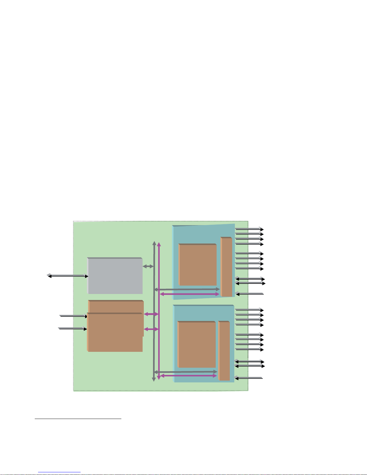
Product Architecture
The 8949MDA-CFR and 8949MDA-SFR can only be installed in the GeckoFlex
frame illustrated in Figure 1 below.
Figure 1. Product Architecture
1.
Please contact your Grass Valley representative for ordering this option (1310NM-DRL)
Frame
Bus
GeckoFlexhousing
(8900FFN)
Ethernet
8900NET
Network Interface Module
Power Supply
Power Supply
(8900F-PSX)
100 - 240 Volts
±12V
Reclocked
SD/HD
on electrical outputs
SD/HD
Gecko HD DA
(8949MDA-CFR)
Front Module
8
9
0
0
W
F
R
R
Front Module
8
9
0
0
W
F
R
R
Gecko HD DA
(8949MDA-SFR)
SD/HD
Reclocked
SD/HD
on electrical outputs
Reclocked SD/HD on
Fiber Optic Submodule
s
Composite downscaled
signals on electrical
outputs
SDI downscaled signals
on electrical outputs
8434-01
Reclocked SD/HD on
Fiber Optic Submodules
8949MDA-CFR and 8949MDA-SFR Instruction Manual 9
Introduction
Product Environment
The 8949MDA-CFR and 8949MDA-SFR modules can only be installed in a GeckoFlex frame (8900FF, 8900FX and 8900FFN). The devices can be located in
broadcast centers, video production facilities, OB vans and production trucks. The
main application of those products is the jitter reduction, the distribution of the
incoming SD or HD signals to the video processing devices (routers, switchers,
tape recorder, monitoring devices, etc.) and the downscaling of HD video signals
to SD or composite video signals for monitoring applications.
Software Version Requirement
This manual covers two software versions. It is important to distinguish the board
version (hardware implementation) related to the software version.
Note The part number is given on the Status web page if the 8900NET module is
present. And it is written on the module.
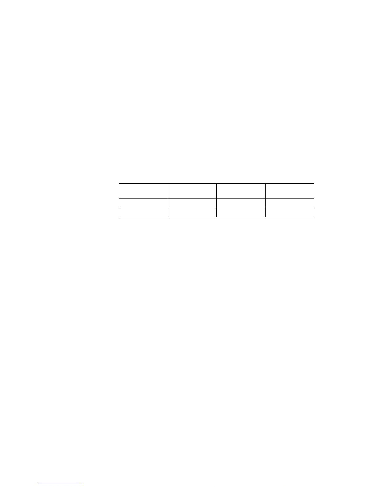
Table 1. Hardware/Software Compatibility
Model
Board Part Number
from 1.0.6 Version
Board Part Number
from 2.0.2 Version
Board Part Number
from 2.0.4 Version
8949MDA-CFR 671-6708-10 671-6708-11 771-0283-10
8949MDA-SFR 671-6708-20 671-6708-21 771-0283-20
10 8949MDA-CFR and 8949MDA-SFR Instruction Manual
Installation
Installation
The front and the rear modules (Cabling on page 14) are delivered together as a set.
The 8949MDA-CFR and 8949MDA-SFR front modules can be plugged in and
removed from a GeckoFlex frame with power on, without disrupting operation on
adjacent running modules. When power is applied to the module, LED indicators
reflect the initialization process (see Power Up on page 16).
CAUTION It is advised to take precautions for the installation and the removal
of the optional fiber optic submodule, see Optional Fiber Optic Submodule on page 12.
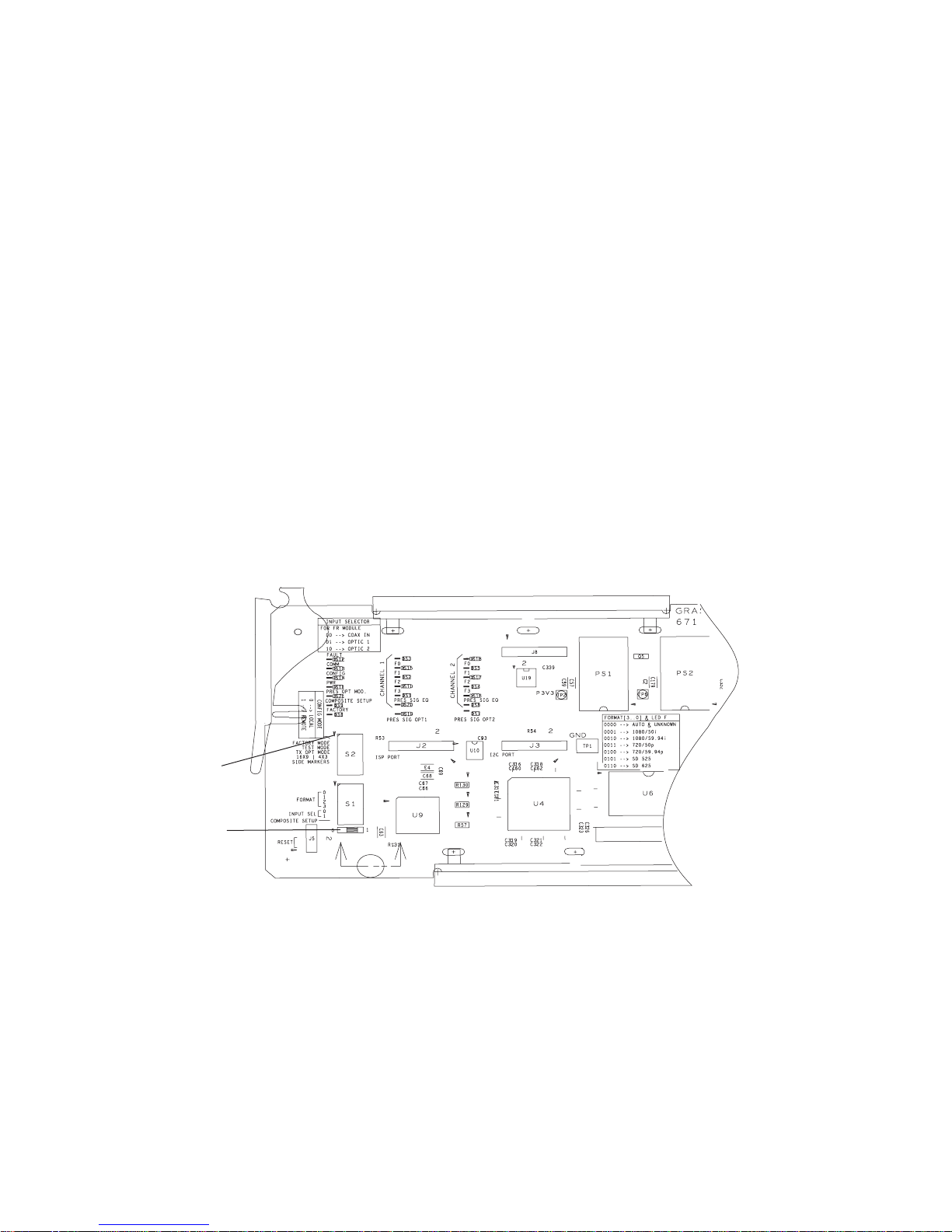
Local Configuration
Local configuration of the 8949MDA-CFR and 8949MDA-SFR consists of several
switches (S1 and S2 blocks) as shown in Figure 2.
If you do not have an 8900NET module, you will need to configure the module
using the local onboard controls before installing the front module.
Figure 2. Switches on 8949MDA Module
Config mode
Switch position
8434-02
8949MDA-CFR and 8949MDA-SFR Instruction Manual 11
Installation
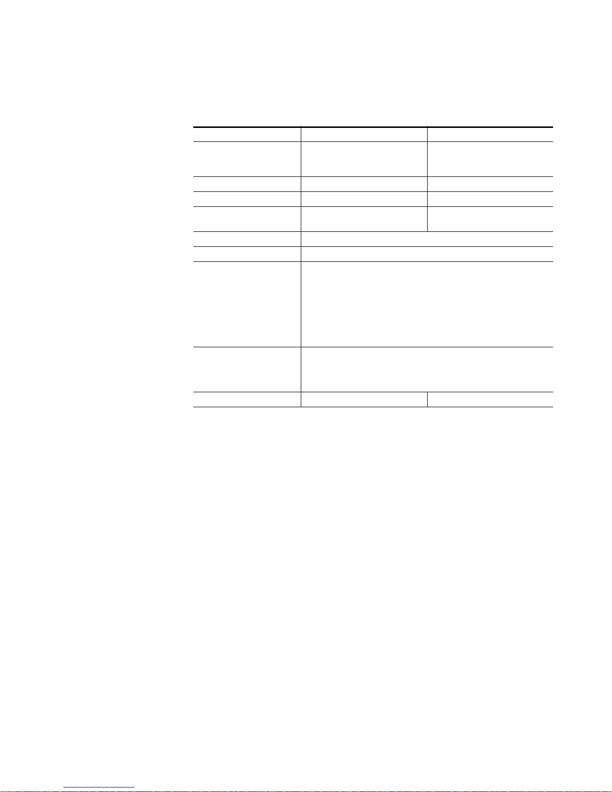
Table 2 gives the parameter to be set with the onboard switches of the 8949MDA
modules.
Module Placement in the GeckoFlex Frame
There are ten rear and front slot locations in the 2 RU frame to accommodate either
analog or digital modules. The 8949MDA-CFR or 8949MDA-SFR module can be
plugged into any one of the GeckoFlex frame slots.
Note As the module can be changed when the GeckoFlex is powered on,
before removing the cover, please put an anti-static bracelet tied to a
metal part of the frame.
Rear Module Installation
Note Never completely remove the screws which maintain the retainer strips.
To install a rear module into the frame, follow these steps:
1. Unscrew the blank rear adapter cover without removing the screws, see
Figure 3.
2. Remove the two retainer strips and the blank rear adapter cover using a
needlenose plier.
Table 2. Switch S1 and S2 Positions
Position 0 1
CONFIG MODE Local mode: the other switches must
be manually positioned
Remote mode: the other parameters
wil be positioned by the web pages
via the NetConfig application
FACTORY MODE OFF For maintenance only
TEST MODE OFF For maintenance only
TX OPT MODE OFF ON (enables the transmission through
the fiber optic submodule)
16X9 I 4X3 UNUSED
SIDE MARKERS UNUSED
FORMAT Selection of the incoming format:
0000 = AUTO
0001 = 1080I/50
0010 = 1080I/59.94
0011 = 720p/50
0100 = 720p/59.94
0101 = 480i/59.94
0110 = 576i/50
INPUT SEL
coax in
optic 1
optic 2
Selection of the input connectors:
00
01
10
COMPOSITE SETUP OFF ON
 Loading...