

Page 1
8949MDA-CXF/-SXF
HD/SD MONITORING DAs
Instruction Manual
Software Version 2.0.1
071856301
APRIL 2010
Page 2

Affiliate with the N.V. KEMA in The Netherlands
CERTIFICATE
Certificate Number: 510040.001
The Quality System of:
Thomson Inc, and it’s wordwide Grass Valley division affiliates DBA
GRASS VALLEY
Headquarters
400 Providence Mine Rd
Nevada City, CA 95959
United States
15655 SW Greystone Ct.
Beaverton, OR 97006
United States
10 Presidential Way
Suite 300
Woburn, MA 01801
United States
Kapittelweg 10
4827 HG Breda
The Nederlands
7140 Baymeadows Way
Ste 101
Jacksonville, FL 32256
United States
2300 So. Decker Lake Blvd.
Salt Lake City, UT 84119
United States
Rue du Clos Courtel
CS 31719
35517 Cesson-Sevigné Cedex
France
1 rue de l’Hautil
Z.I. des Boutries BP 150
78702 Conflans-Sainte
Honorine Cedex
France
Technopole Brest-Iroise
Site de la Pointe du Diable
CS 73808
29238 Brest Cedex 3
France
40 Rue de Bray
2 Rue des Landelles
35510 Cesson Sevigné
France
Spinnereistrasse 5
CH-5300 Turgi
Switzerland
Brunnenweg 9
D-64331 Weiterstadt
Germany
Carl-Benz-Strasse 6-8
67105 Schifferstadt
Germany
Including its implementation, meets the requirements of the standard:
ISO 9001:2008
Scope:
The design, manufacture and support of video and audio hardware and software products and
related systems
.
This Certificate is valid until: June 14, 2012
This Certificate is valid as of: June 14, 2009
Certified for the first time: June 14, 2000
H. Pierre Sallé
President
KEMA-Registered Quality
The method of operation for quality certification is defined in the KEMA General Terms
And Conditions For Quality And Environmental Management Systems Certifications.
Integral publication of this certificate is allowed.
KEMA-Registered Quality, Inc.
4377 County Line Road
Chalfont, PA 18914
Ph: (215)997-4519
Fax: (215)997-3809
CRT 001 073004
ccredited By:
ANAB
A
Page 3

8949MDA-CXF/-SXF
HD/SD MONITORING DAs
Instruction Manual
Software Version 2.0.1
071856301
APRIL 2010
Page 4
Contacting Grass Valley
International
Support Centers
Local Support
Centers
(available
during normal
business hours)
France
24 x 7
Australia and New Zealand: +61 1300 721 495 Central/South America: +55 11 5509 3443
Middle East: +971 4 299 64 40 Near East and Africa: +800 8080 2020 or +33 1 48 25 20 20
Europe
+800 8080 2020 or +33 1 48 25 20 20
Hong Kong, Taiwan, Korea, Macau: +852 2531 3058 Indian Subcontinent: +91 22 24933476
Asia
Southeast Asia/Malaysia: +603 7805 3884 Southeast Asia/Singapore: +65 6379 1313
China: +861 0660 159 450 Japan: +81 3 5484 6868
Belarus, Russia, Tadzikistan, Ukraine, Uzbekistan: +7 095 2580924 225 Switzerland: +41 1 487 80 02
S. Europe/Italy-Roma: +39 06 87 20 35 28 -Milan: +39 02 48 41 46 58 S. Europe/Spain: +34 91 512 03 50
Benelux/Belgium: +32 (0) 2 334 90 30 Benelux/Netherlands: +31 (0) 35 62 38 42 1 N. Europe: +45 45 96 88 70
Germany, Austria, Eastern Europe: +49 6150 104 444 UK, Ireland, Israel: +44 118 923 0499
Copyright © Grass Valley, Inc. All rights reserved.
This product may be covered by one or more U.S. and foreign patents.
United States/Canada
24 x 7
+1 800 547 8949 or +1 530 478 4148
Grass Valley Web Site
The www.grassvalley.com web site offers the following:
Online User Documentation — Current versions of product catalogs, brochures,
data sheets, ordering guides, planning guides, manuals, and release notes
in .pdf format can be downloaded.
FAQ Database — Solutions to problems and troubleshooting efforts can be
found by searching our Frequently Asked Questions (FAQ) database.
Software Downloads — Download software updates, drivers, and patches.
4 8949MDA-CXF/-SXF — Instruction Manual
Page 5

Contents
Preface. . . . . . . . . . . . . . . . . . . . . . . . . . . . . . . . . . . . . . . . . . . . . . . . . . . . . . . . . . . . . . . . . . . . . 7
8949MDA-CXF and 8949MDA-SXF Modules . . . . . . . . . . . . . . . . . . . . . . . . . . . . 9
About This Manual . . . . . . . . . . . . . . . . . . . . . . . . . . . . . . . . . . . . . . . . . . . . . . . . . . . . . 7
Introduction . . . . . . . . . . . . . . . . . . . . . . . . . . . . . . . . . . . . . . . . . . . . . . . . . . . . . . . . . . . 9
Features . . . . . . . . . . . . . . . . . . . . . . . . . . . . . . . . . . . . . . . . . . . . . . . . . . . . . . . . . . . . 10
Installation . . . . . . . . . . . . . . . . . . . . . . . . . . . . . . . . . . . . . . . . . . . . . . . . . . . . . . . . . . . 11
Local Configuration . . . . . . . . . . . . . . . . . . . . . . . . . . . . . . . . . . . . . . . . . . . . . . . . . 11
Configuration Switches S1 and S2. . . . . . . . . . . . . . . . . . . . . . . . . . . . . . . . . . . . 12
Module Placement in the GeckoFlex Frame . . . . . . . . . . . . . . . . . . . . . . . . . . . . . 13
Module Installation Precautions . . . . . . . . . . . . . . . . . . . . . . . . . . . . . . . . . . . . . 14
Rear Module Installation . . . . . . . . . . . . . . . . . . . . . . . . . . . . . . . . . . . . . . . . . . . 15
Fiber Optics Submodule Overview. . . . . . . . . . . . . . . . . . . . . . . . . . . . . . . . . . . 16
Fiber Optic Cleaning Requirement . . . . . . . . . . . . . . . . . . . . . . . . . . . . . . . . . . . 17
Install Mounting Bracket on Submodule . . . . . . . . . . . . . . . . . . . . . . . . . . . . . . 17
Fiber Optic Submodule Installation . . . . . . . . . . . . . . . . . . . . . . . . . . . . . . . . . . 18
Front Module Installation. . . . . . . . . . . . . . . . . . . . . . . . . . . . . . . . . . . . . . . . . . . 20
Cabling . . . . . . . . . . . . . . . . . . . . . . . . . . . . . . . . . . . . . . . . . . . . . . . . . . . . . . . . . . . . . . 21
Video Input. . . . . . . . . . . . . . . . . . . . . . . . . . . . . . . . . . . . . . . . . . . . . . . . . . . . . . . . . 21
Video Outputs . . . . . . . . . . . . . . . . . . . . . . . . . . . . . . . . . . . . . . . . . . . . . . . . . . . . . . 22
Cabling . . . . . . . . . . . . . . . . . . . . . . . . . . . . . . . . . . . . . . . . . . . . . . . . . . . . . . . . . . . . . . 23
Power Up . . . . . . . . . . . . . . . . . . . . . . . . . . . . . . . . . . . . . . . . . . . . . . . . . . . . . . . . . . . . 25
Operation Indicator LEDs . . . . . . . . . . . . . . . . . . . . . . . . . . . . . . . . . . . . . . . . . . . . 25
Configuration. . . . . . . . . . . . . . . . . . . . . . . . . . . . . . . . . . . . . . . . . . . . . . . . . . . . . . . . . 27
Local Onboard Configuration with no 8900NET Module. . . . . . . . . . . . . . . . . . 27
Web Browser Configuration with 8900NET Module. . . . . . . . . . . . . . . . . . . . . . 27
Newton Control Panel Configuration . . . . . . . . . . . . . . . . . . . . . . . . . . . . . . . . . . 27
Web Browser Interface . . . . . . . . . . . . . . . . . . . . . . . . . . . . . . . . . . . . . . . . . . . . . . . 28
8949MDA-CXF and 8949MDA-SXF Links and Web Pages. . . . . . . . . . . . . . . . . 31
Status Web Page. . . . . . . . . . . . . . . . . . . . . . . . . . . . . . . . . . . . . . . . . . . . . . . . . . . 32
Settings Web Page . . . . . . . . . . . . . . . . . . . . . . . . . . . . . . . . . . . . . . . . . . . . . . . . . 37
Slot Config Web Page . . . . . . . . . . . . . . . . . . . . . . . . . . . . . . . . . . . . . . . . . . . . . . 45
Software Updating . . . . . . . . . . . . . . . . . . . . . . . . . . . . . . . . . . . . . . . . . . . . . . . . . . . . 47
Status Monitoring . . . . . . . . . . . . . . . . . . . . . . . . . . . . . . . . . . . . . . . . . . . . . . . . . . . . . 48
External Frame Alarm. . . . . . . . . . . . . . . . . . . . . . . . . . . . . . . . . . . . . . . . . . . . . . . . 48
LED Reporting . . . . . . . . . . . . . . . . . . . . . . . . . . . . . . . . . . . . . . . . . . . . . . . . . . . . . . 49
Web Browser Interface . . . . . . . . . . . . . . . . . . . . . . . . . . . . . . . . . . . . . . . . . . . . . . . 49
SNMP Reporting . . . . . . . . . . . . . . . . . . . . . . . . . . . . . . . . . . . . . . . . . . . . . . . . . . . . 49
Specifications . . . . . . . . . . . . . . . . . . . . . . . . . . . . . . . . . . . . . . . . . . . . . . . . . . . . . . . . . 50
Attenuation Requirements . . . . . . . . . . . . . . . . . . . . . . . . . . . . . . . . . . . . . . . . . . 52
Service. . . . . . . . . . . . . . . . . . . . . . . . . . . . . . . . . . . . . . . . . . . . . . . . . . . . . . . . . . . . . . . 53
Power-up Diagnostics Failure . . . . . . . . . . . . . . . . . . . . . . . . . . . . . . . . . . . . . . . . . 53
Troubleshooting. . . . . . . . . . . . . . . . . . . . . . . . . . . . . . . . . . . . . . . . . . . . . . . . . . . . . 53
Electronic Circuit Breaker. . . . . . . . . . . . . . . . . . . . . . . . . . . . . . . . . . . . . . . . . . . 53
8949MDA-CXF/-SXF — Instruction Manual 5
Page 6

Contents
Module Repair. . . . . . . . . . . . . . . . . . . . . . . . . . . . . . . . . . . . . . . . . . . . . . . . . . . . . . 53
Table of Alarms . . . . . . . . . . . . . . . . . . . . . . . . . . . . . . . . . . . . . . . . . . . . . . . . . . . 54
Functional Description . . . . . . . . . . . . . . . . . . . . . . . . . . . . . . . . . . . . . . . . . . . . . . . . 55
Configuration Summary Table. . . . . . . . . . . . . . . . . . . . . . . . . . . . . . . . . . . . . . . . . . 57
Index. . . . . . . . . . . . . . . . . . . . . . . . . . . . . . . . . . . . . . . . . . . . . . . . . . . . . . . . . . . . . . . . . . . . . . 59
6 8949MDA-CXF/-SXF — Instruction Manual
Page 7

Preface
About This Manual
This manual describes the features of the 8949MDA-CXF and
8949MDA-SXF modules in the GeckoFlex Signal Processing System family.
As part of this module family, it is subject to Safety and Regulatory Com
pliance described in the GeckoFlex Frames 8900FX/FF/FFN Signal Processing
System Instruction Manual.
All Modular product manuals can be found on-line in PDF format at this
link:
www.grassvalley.com/docs/modular
-
8949MDA-CXF/-SXF — Instruction Manual 7
Page 8

Preface
8 8949MDA-CXF/-SXF — Instruction Manual
Page 9

8949MDA-CXF and 8949MDA-SXF Modules
Introduction
The 8949MDA-CXF or 8949MDA-SXF module performs HD/SD equalization and reclocking for distribution of SD/HD signals. It also provides four
dedicated downscaled electrical outputs for viewing the input video in
SD-SDI format (with the 8949MDA-SXF module) or composite format
(with the 8949MDA-CXF module), with aspect ratio controls for down
scaled HD video on both models.
The 8949MDA-CXF module will distribute the original SD-SDI or HD-SDI
input signal on four dedicated electrical outputs as well as up to two
optional fiber optic outputs. The input signal from one electrical input or
one of two optional fiber optic inputs is downscaled to composite video
and distributed from four dedicated electrical outputs. Controls are pro
vided for setting the aspect ratio of downscaled HD video for the desired
monitor viewing. A color bars test signal may be enabled and a control is
provided for enabling or disabling setup on NTSC outputs.
-
-
The 8949MDA-SXF module will distribute the original SD-SDI or HD-SDI
input signal on four dedicated electrical outputs as well as up to two
optional fiber optic outputs. The input signal from one electrical input or
one of two optional fiber optic inputs is downscaled to SD-SDI video and
distributed from four dedicated electrical outputs. Only the EDH CRC
packet data from the original video input is included in the downscaled
output signal. Controls are provided for setting the aspect ratio of down
scaled HD video for the desired monitor viewing.
The aspect ratio controls include Anamorphic, Letterbox, 4x3 Center Cut,
or 14x9 Center Cut. Aspect ratio controls are only available when an HD
input signal is being downscaled.
Fiber optic interfaces can be added by ordering one of three types of
optional SFP Fiber optic submodule kits to add two fiber inputs (Dual
Receiver), two fiber outputs (Dual Transmitter), or one fiber input and one
fiber output (Transceiver). The optional SFP strap-mount optical sub
module device is mounted on the module circuit board and must be
ordered separately. See
8949MDA-CXF/-SXF — Instruction Manual 9
Ta bl e 2 on page 16 for submodule types.
-
-
Page 10

Introduction
Features
The two models must be installed in a GeckoFlex frame and require the
presence of an 8900WFR-XFR rear module. Parameters can be set with local
onboard controls or using remote controls (web browser or Newton
Control Panel when an 8900NET (Net Card) module is present in the frame.
The 8949MDA-CXF and 8949MDA-SXF module features include:
• Multi-format HD/SD video input on one electrical input or one of two
optional fiber optic inputs (only one input active at a time),
• Outputs for the 8949MDA-CXF module include:
• Four reclocked SD/HD electrical outputs and two optional
reclocked SD/HD fiber optic outputs distributing the original input
signal (all outputs can be active at the same time),
• Four electrical composite outputs for monitor viewing downscaled
HD or SD video and a color bars test signal and NTSC setup controls, with aspect ratio controls for HD video signals,
• Outputs for the 8949MDA-SXF module include:
• Four reclocked SD/HD electrical outputs and two optional
reclocked SD/HD fiber optic outputs (with optional fiber submodule) distributing the original input signal (all outputs can be
active at the same time),
• Four electrical SDI outputs for monitor viewing (generating a new
EDH CRC packet on the output signal) with aspect ratio controls for
HD video signals,
• Aspect ratio controls include Anamorphic, LetterBox, 4x3 Center Cut,
or 14x9 Center Cut for downscaled HD video,
• One strap-mount SFP fiber optic submodule option can be installed to
add up to two fiber optic inputs (only one input active at a time) and up
to two fiber outputs (both active) depending on the option model. Refer
to the list of available options in Table 2 on page 16,
• Auto cable equalization for up to 330m of cable in the case of SD signals
and for up to 125m of cable in the case of HD signals,
• Alarm (signal presence detection) and status management,
• SNMP and product health monitoring is supported through the
8900NET (Net Card) module with applications such as NetCentral, and
• Remote control and monitoring support: web pages, Newton control
panel, NetConfig management system.
10 8949MDA-CXF/-SXF — Instruction Manual
Page 11
Installation
Local configuration
switches S1 and S2
Local Configuration
Installation
The front and the rear modules are delivered together as a set:
8949MDA-CXF front module with the 8900WFR-XFR rear module or
8949MDA-SXF front module with 8900WFR-XFR rear module. Fiber optic
submodules are optional and must be ordered separately. Fiber optic sub
module options available are listed in Tab le 2 on page 16.
The 8949MDA-CXF and 8949MDA-SXF front modules can be plugged in
and removed from a GeckoFlex frame with power on. When power is
applied to the module, LED indicators reflect the initialization process (see
Power Up on page 25).
CAUTION Use anti-static precautions when installing and removing the optional fiber
optic submodule, see Fiber Optics Submodule Overview on page 16.
If there is no 8900NET (Net Card) module in the GeckoFlex frame for
remote monitoring and configuration, you will need to configure the
module using the local onboard controls before installing the front module.
-
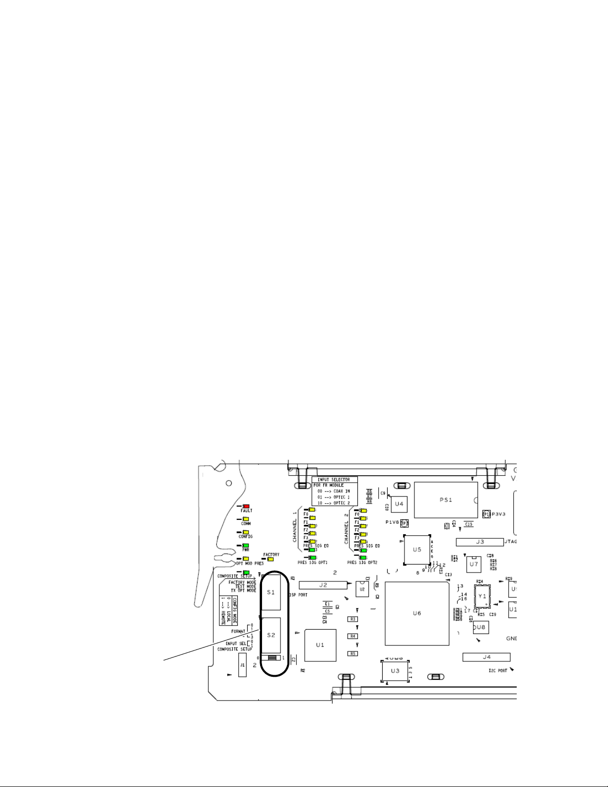
Local configuration of the 8949MDA modules consists of two DIP switches
(S1 and S2) highlighted in
local controls. A summary of Local and Remote (web page and Newton
Control Panel) parameters is provided in
Figure 2 and Tab le 1 on page 12 for using S1 and S2.
Figure 1. Configuration Switches on 8949MDA Module
Figure 1. Not all parameters can be set using the
Ta bl e 9 on page 57. Refer to
8949MDA-CXF/-SXF — Instruction Manual 11
Page 12
Installation
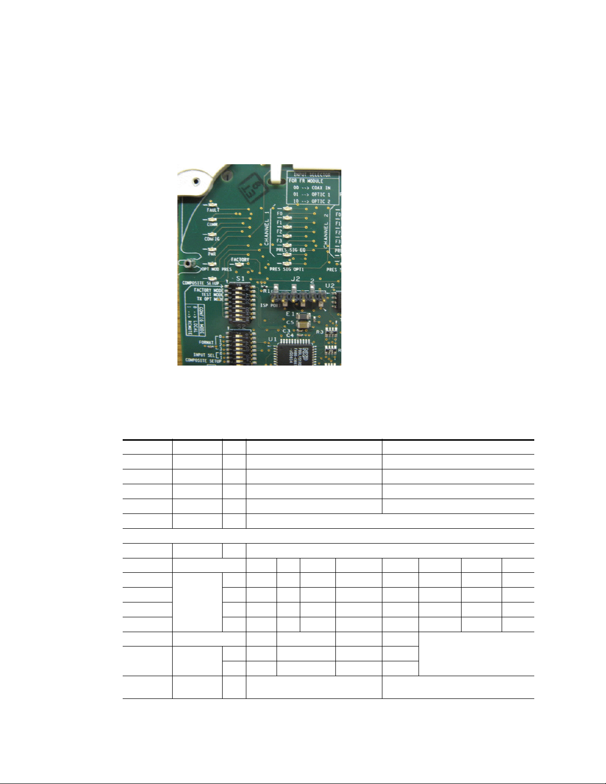
Configuration Switches S1 and S2
Figure 2 gives a photographic illustration of switches S1 and S2 and related
silkscreened information. Ta bl e 1 gives the parameters set with the
onboard switches S1 and S2 on the 8949MDA module circuit board.
Figure 2. Onboard Configuration Switches, S1 and S2
Note Remote control settings made with the web interface will override local set-
tings. To lock out remote control, set the Config Mode to Off.
Table 1. Switch S1 and S2 Settings
Switch 1 Function Pin 0 (Left/Off) 1 (Right/On)
Config Mode
Factory Mode
Test Mode
Tx Opt Mode
Switch S2
Composite
1
Fiber optic outputs are present when an optional Transmitter submodule (TX1 and TX2) or a Transceiver submodule (TX2) is installed.
1
–
–
Format (Input) Setting Auto 1080i/50 1080i/59.94 720p/50 720p/59.94 480i/59.94 576i/50
Input Select Setting Coax In Optic 1 Optic 2
Setup
Local mode (Remote control locked out) Remote mode
1
2
3
4
5-8
1
2
3
4
5
6
7
8
Off (fiber optic outputs disabled) On (fiber optic outputs enabled)
00 0 0 0 0 0 0
10 0 0 0 1 1 1
20 0 1 1 0 0 1
30 1 0 1 0 1 0
00 01
10 10
Off Factory use only
Off Factory use only
Not Used
Not Used
Off On
12 8949MDA-CXF/-SXF — Instruction Manual
Page 13
Module Placement in the GeckoFlex Frame
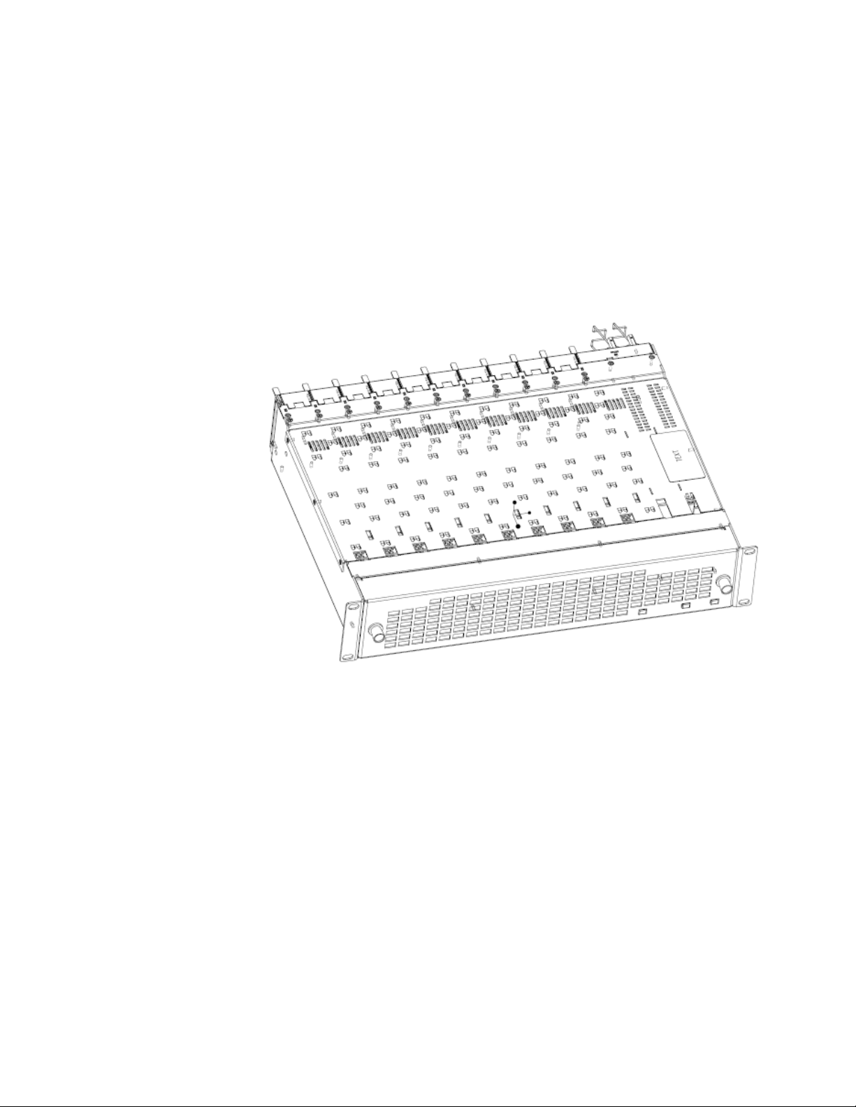
There are ten rear and front slot locations in the 2 RU frame to accommodate audio/video modules (Figure 3). The 8949MDA-CXF/-SXF module
set may be plugged into any one of the available GeckoFlex frame slots. The
module requires a single rear slot.
Note Use anti-static precautions when handling the module. As the module can be
changed when the GeckoFlex is powered on, before removing the cover,
please put an anti-static bracelet tied to a metal part of the frame.
Figure 3. GeckoFlex Frame
Installation
8949MDA-CXF/-SXF — Instruction Manual 13
Page 14

Installation
Module Installation Precautions
Please read and follow the precautions listed below before installing the
front and rear modules, and any fiber optic option submodules:
• Use standard anti-static procedures during installation. As modules
can be installed or removed when the GeckoFlex frame is powered up,
before removing the cover, please use an anti-static bracelet or heel
strap tied to a metal part of the frame.
• Install the rear module first, then the fiber optic submodule option (if
used) on the back of the front module circuit board, then install the
front module.
Note If using onboard configuration, set the configuration switches described in
Configuration Switches S1 and S2 on page 12 first before installing the front
module.
• When installing or removing a rear module, loosen or tighten the
screws holding the retainer clips to the frame manually with the
retainer clip tool provided inside the front cover of the frame or use a
2 mm (5/64”) hex screwdriver. Please do not use an electric screwdriver.
Note On newer 751- version GeckoFlex frames, a Rear Retainer Clip removal tool
and 2 extra retainer clips and screws for installing them are provided on the
inside of the frame cover.
• Make every effort to leave the screws holding the retainer clips in place
(do not remove them completely). They are very small and can easily
drop into other equipment causing a shorting hazard. (Two turns of the
screw should be enough to loosen the screws, 3 turns or more will
remove it.)
• When installing a rear module, tighten the screws on the retainer clips
just until snug. Do not apply more force than is necessary to seat the
rear module. Do not use an electric screwdriver. Refer to the rear
retainer screw torque specification in the
page 50.
Mechanical section of Tab le 5 on
14 8949MDA-CXF/-SXF — Instruction Manual
Page 15
Rear Module Installation
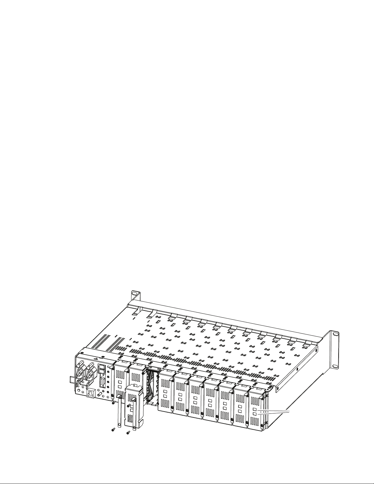
To install the rear module, refer to Figure 4 and the instructions below:
1. To remove a blank rear adapter cover (or a rear module already
present), manually loosen the two screws holding each retainer clip on
the rear adapter cover or rear module to the frame with the retainer clip
tool provided inside the front cover of the frame (newer model frames
only) or a 2 mm (5/64”) hex screwdriver. Do not remove the screws.
Note To remove a rear module already installed, follow the same steps. It is helpful
to first remove the front module so the rear can be pulled out more easily.
1. After loosening the retainer clip screws, pull up on each retainer and
completely remove it, leaving the screws in place.
2. Remove the blank rear adapter cover by inserting needlenose pliers or
the retainer clip into the slots in the blank cover and pulling it off.
3. Insert the rear module into the empty slot, guiding it carefully.
4. Replace each retainer clip over the two screws on both sides of the
module and push down to seat the retainer clip.
Installation
5. Tighten the two screws on each retainer clip just until they come into
contract with the retainer clip then tighten about a 1/4 turn more
(maximum torque specification is 4-5 inch lb/0.45-0.6 Nm). Do not
force or torque the screws too tightly. Clips should not bend or bow.
Note All unused rear slots in a GeckoFlex frame should have a blank rear adapter
cover installed.
Figure 4. Installing Rear Module (751- Version Frame)
8444_23r0
Use retainer clip or
needlenose pliers
to pull out blank after
removing retainer clips
8949MDA-CXF/-SXF — Instruction Manual 15
Page 16
Installation
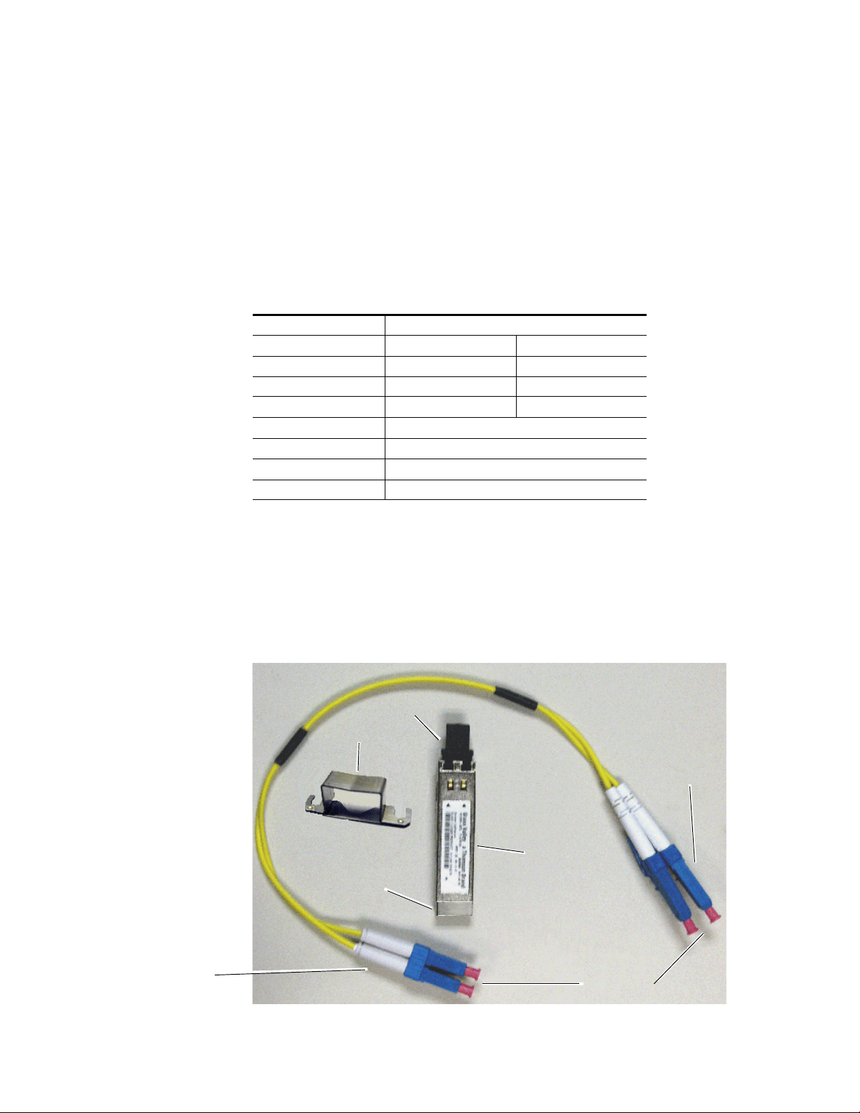
Ferrule covers
Duplex end ferrules
Simplex end ferrules
Mounting Bracket
Submodule dust cover
Submodule Label
SCA-2 Connector
Fiber Optics Submodule Overview
Before installing the front module, if using an optional SFP submodule,
install it on the front module first. For a list of the SFP fiber optic submod
ules options available, refer to Ta bl e 2. If not using a submodule, proceed
to Front Module Installation on page 20.
The 8949MDA front modules can be populated with any one of the SFP
(Strap Mount Video Small Form-factor Pluggable) dual transmitter, trans
ceiver, or dual receiver submodules listed in Ta bl e 2.
Table 2. SFP Fiber Optic Submodule Option Models
SFP Model Number Transmitter Frequencies Supported
SFP-CWDM3G-1-K 1470 nm 1490 nm
SFP-CWDM3G-2-K 1510 nm 1530 nm
SFP-CWDM3G-3-K 1550 nm 1570 nm
SFP-CWDM3G-4-K 1590 nm 1610 nm
Receiver Frequencies Supported
SFP-13103G-M1DRX-K 1270 nm >1610 nm
Transceiver Frequencies Supported
SFP-13103G-M1TRX-K 1310 nm (input) and 1310 nm (output)
-
-
If you have ordered an SFP fiber optic submodule it will come in a separate
kit with an SFP fiber optic submodule, a mounting bracket, and a 2-channel
fiber jumper cable assembly (shown in
Figure 5). The fiber optic connector
ends (ferrules) are protected by covers that must be removed before
cabling.
Figure 5. SFP Fiber Optic Kit
16 8949MDA-CXF/-SXF — Instruction Manual
Page 17
Fiber Optic Cleaning Requirement
V-connection
SCA-2 (electrical) connector
Jumper cable connectors
SCA-2 (electrical) connector
Before making any fiber optic cable mating connections and after every
de-mating cycle, use an industry standard fiber optic cleaning kit,
including oil-free compressed air, to clean the fiber connectors and the con
nectorized fiber end ferrules. This helps ensure optimum performance of
the fiber optic interface. Industry standard fiber optic cleaning kits can be
purchased on the web and in electronics stores.
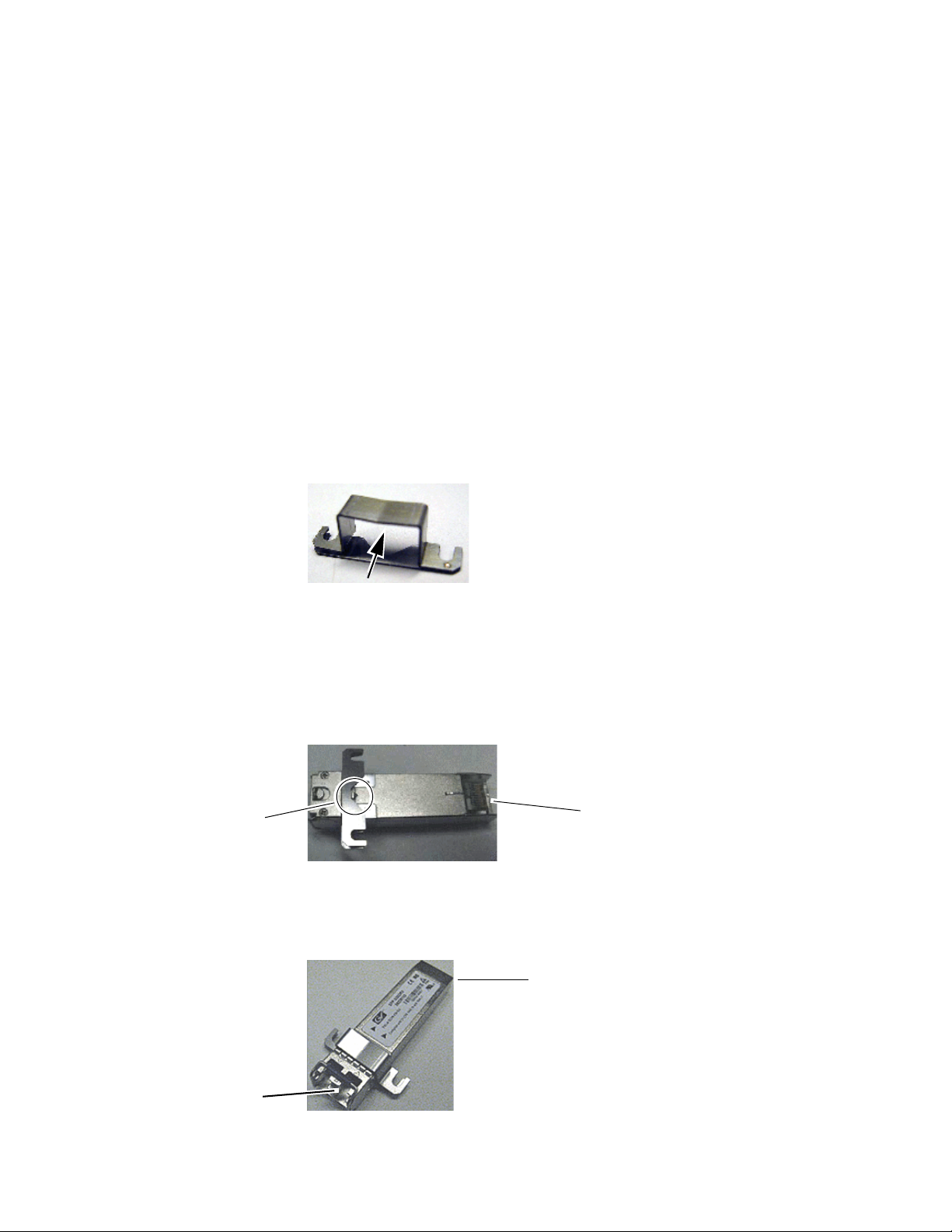
Install Mounting Bracket on Submodule
Install the mounting bracket onto the submodule as illustrated below.
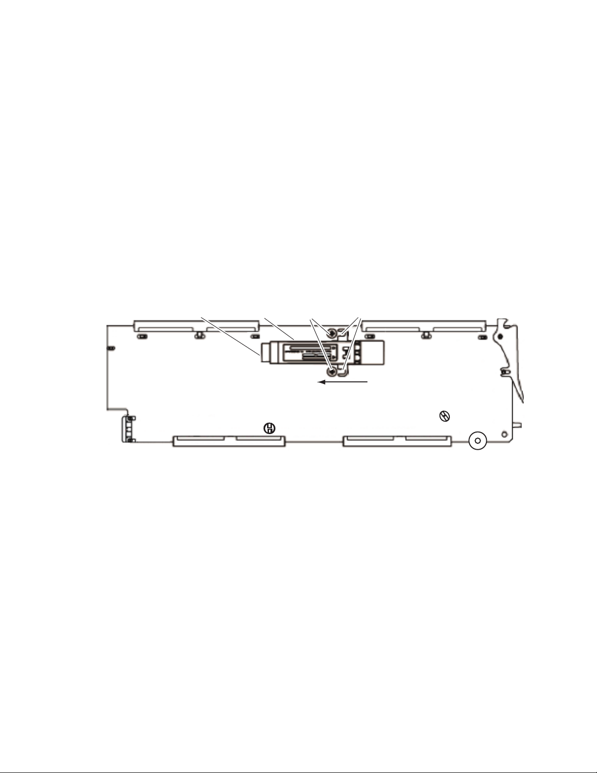
1. Insert the narrow end (SCA-2 connector) of the submodule into the
mounting bracket, label side up with the open slots on the bracket
pointing to the rear as shown by the direction of the arrow in Figure 6.
Figure 6. Mounting Bracket
Installation
-
2. Attach the mounting bracket to the submodule by sliding the bottom
part of the bracket under the V-connection (Figure 7) on the bottom side
of the submodule to hold it in place. Make sure the open bracket slots
point towards the SCA-2 (electrical) connector on the submodule.
Figure 7. Attach Bottom of Bracket to Submodule
3. The finished installation should look like the example in Figure 8.
Figure 8. Finished Bracket Mounting
8949MDA-CXF/-SXF — Instruction Manual 17
Page 18
Installation
SCA-2 connector
Submodule Screws
Straps
Slide submodule straps under
screws and tighten.
Insert end of submodule
into SCA-2 connector.
8567_01r0
Fiber Optic Submodule Installation
Once the bracket has been installed on the submodule, install the fiber optic
submodule on the back (solder) side of the 8949MDA-CXF or
8949MDA-SXF front module, as follows.
1. Remove the black rubber dust cover from the submodule.
2. On the back (solder) side of the front module, locate the two screws and
the SCA-2 connector where the submodule will be installed (Figure 9).
3. Loosen the two screws slightly so you can slide the submodule bracket
straps underneath the screws and the SCA-2 connector end of the
submodule slides over the SCA-2 connector.
4. Once the submodule is seated into the SCA-2 connector and the straps
are completely under the screws, tighten the screws to hold the
submodule in place.
Figure 9. Installing Strap-Mount SFP Submodule
5. Before installing the jumper cable assembly, remove the protective
covers from the ferrule ends of the cable and clean all fiber optic
surfaces on the duplex and simplex connectors of the 2-channel fiber
jumper cable assembly and the SFP submodule connector with a
standard fiber optic cleaning kit as described in Fiber Optic Cleaning
Requirement on page 17.
18 8949MDA-CXF/-SXF — Instruction Manual
Page 19
Installation
Plastic cable guides
Rear Fiber
Connector
Simplex Connector
for Channel A
Simplex Connector
for Channel B
Fiber jumper cable assembly
8567_02r0
Connect Channel A to top connector (not labeled).
Connect Channel B to bottom connector (not labeled).
A
A
B
B
Duplex connector end
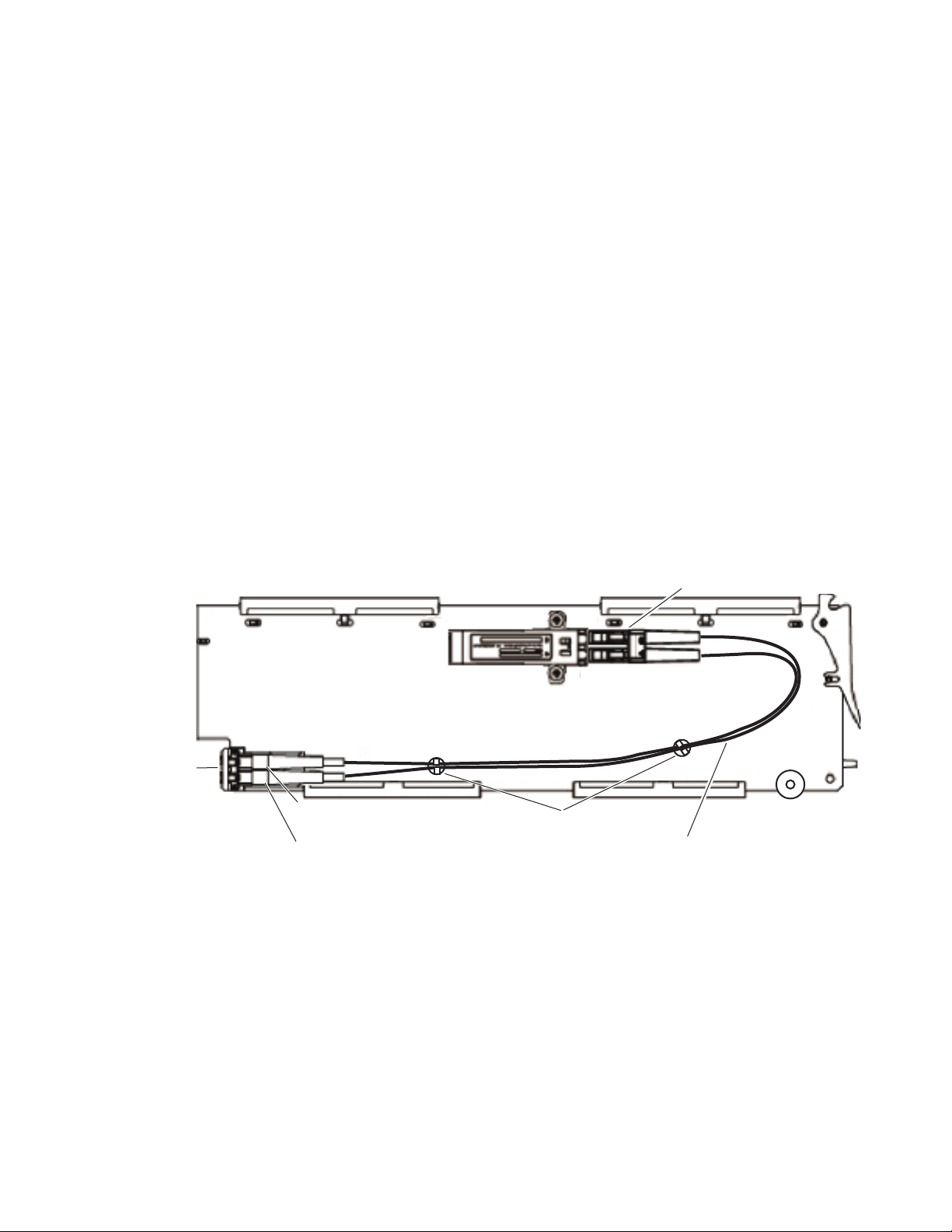
6. After removing the covers and cleaning the fiber optic connectors,
carefully attach the duplex ferrule end of the 2-channel fiber jumper
cable assembly to the submodule until the two connectors snap into
place (top of Figure 10).
7. Guide the 2 fiber jumper cables around towards the front of the board
and slip them through the two white plastic cable guides to hold them
in place.
8. Find the ferrule end of the simplex (single) fiber jumper cable that
corresponds to the top duplex cable (labeled A for clarity in this
illustration) and after removing the protective cover and cleaning the
connector, connect it to the bottom of the rear fiber connector (labeled
A) as shown in Figure 10.
9. Find the ferrule end of the simplex (single) fiber jumper cable that
corresponds to the bottom duplex cable (labeled B) and after removing
the protective cover and cleaning the connector, connect it to the bottom
of the rear fiber connector (labeled B) as shown at the bottom of
Figure 10.
10. This completes the installation of the submodule.
Figure 10. Installing Fiber Jumper Cables
8949MDA-CXF/-SXF — Instruction Manual 19
Page 20

Installation
Front Module Installation
After installing the rear module and the fiber optic submodule option if
purchased, if an 8900NET (Net Card) is not present in the frame, configure
the module with front edge onboard controls as described in
Switches S1 and S2 on page 12, before installing the front module. If you
have an 8900NET card, follow the configuration instruction in Configuration
on page 27 after installing the front module:
1. Remove the front cover of the frame if required.
2. Locate the front slot corresponding to the corresponding rear module.
3. Insert the front module so that the plastic card guides on the module
top and bottom edges go over the upper and lower raised rail guides on
the right of the top and bottom of the slot (Figure 11).
4. Carefully slide the module into the rear connector, making sure the
fiber optic rear connector is properly aligned.
5. Lock the front module ejector tab into the locking pin.
Configuration
Figure 11. Front Module Installation
Card Carriers
Card Carriers
Front Module Side View
Locking Pin
8543_02
Module installed
Slide top and bottom card carriers on module
over top and bottom guides on right of slot.
20 8949MDA-CXF/-SXF — Instruction Manual
Page 21

Cabling
Cabling
Cabling to the 8949MDA-CXF or 8949MDA-SXF module is done on the
8900WFR-XFR rear module BNCs and the fiber connector when an
optional fiber optic submodule is installed.
Cabling of the rear module depends on presence and type of fiber optic
submodule option listed in
• 8949MDA-CXF/-SXF with no fiber optic submodule option (electrical
only),
• 8949MDA-CXF/-SXF with the Dual Receiver fiber optic submodule,
• 8949MDA-CXF/-SXF with any Dual Transmitter fiber optic submodule, and
• 8949MDA-CXF/-SXF with the Transceiver fiber optic submodule
option.
Note Fiber input and output connections must be cleaned and the protective covers
removed from the cable ends before cabling as described in Fiber Optic
Cleaning Requirement on page 17.
Tab le 2 on page 16 summarized as follows:
Video Input
The 8949MDA-CXF or 8949MDA-SXF will accept any of the video standards listed in the input specifications in Tab le 5 on page 50.
For both module types, the SD or HD video input to the module can be
selected from one of the following three sources, depending on the pres
ence and type of fiber optic submodule option:
• Electrical BNC, J9 (always available)
• Fiber Input RX 1 or RX 2 (requires Dual Receiver submodule), or
• Fiber Input RX 1 (requires Transceiver submodule).
All three sources can be connected but only be one input can be active at
any time. The active input is configured with local onboard controls (
figuration Switches S1 and S2 on page 12) or using the Settings web page
(page 37) or the Newton Control Panel ().
Con-
-
8949MDA-CXF/-SXF — Instruction Manual 21
Page 22

Cabling
Video Outputs
The 8949MDA-CXF or 8949MDA-SXF outputs conform to the video standards listed in the output specifications in Tab le 5 on page 50. Both
modules require the 8900WFR-XFR rear module.
The 8949MDA-CXF has four electrical outputs for distributing the original
SD-SDI or HD-SDI input signal. It also provides four downscaled outputs
for monitoring each output in PAL or NTSC format with controls for
enabling or disabling composite setup (NTSC only) and a composite color
bars test signal, and aspect ratio controls for downscaled HD video.
The 8949MDA-SXF has four electrical outputs that distribute the original
SD-SDI or HD-SDI input signal. It also provides four downscaled moni
toring outputs in SD-SDI format with aspect ratio controls for downscaled
HD video
Electrical outputs are always enabled. Fiber optic outputs must be enabled
during configuration using the local onboard controls (
Switches S1 and S2 on page 12), the Settings web page (page 37), or the
Newton Control Panel.
Configuration
-
Note Fiber optic outputs available depend on the presence and type of fiber optic
submodule installed as listed in Table 2 on page 16.
• Electrical output BNCs (always available and enabled)
• Fiber Output TX 1 and TX 2 (requires Dual Transmitter submodule), or
• Fiber Output TX 2 (requires Transceiver submodule).
22 8949MDA-CXF/-SXF — Instruction Manual
Page 23

Cabling
Cabling
Cabling to the 8949MDA-CXF or 8949MDA-SXF module is done on the
8900WFR-XFR rear module.
For fiber optic submodule option cabling, refer to the following:
• Before making fiber optic connections, refer to the Fiber Optic Cleaning
Requirement on page 17.
• For available submodule types, refer to Table 2 on page 16.
• Attenuation requirements may be necessary on some fiber connections.
Refer to Attenuation Requirements on page 52.
Cabling of the rear module depends on what fiber optic submodule option
is installed as listed below:
• 8949MDA-CXF and 8949MDA-SXF without fiber optic submodule
option (electrical only),
• 8949MDA-CXF and 8949MDA-SXF with Dual Receiver submodule
• 8949MDA-CXF and 8949MDA-SXF with Dual Transmitter submodule,
and
• 8949MDA-CXF and 8949MDA-SXF with Transceiver submodule.
The 8949MDA-CXF and the 8949MDA-SXF will accept any of the video
standards listed in the input specifications in
Tab le 5 on page 50.
Ta bl e 3 gives the inputs and the possible video output connections for the
8900WFR-XFR, the rear modules used with the 8949MDA front modules.
The rear cabling is illustrated in
Figure 12 on page 24 for the
8949MDA-CXF and Figure 13 on page 24 for the 8949MDA-SXF module.
Table 3. 8900WFR-XFR Rear Module Video Cabling
Fiber Optic
Submodule Option
No submodule J9 J1, J3, J5, J7 J2, J4, J6, J8 J2, J4, J6, J8 N/A N/A
Dual Receiver J9 J1, J3, J5, J7 J2, J4, J6, J8 J2, J4, J6, J8 RX: 1270 to 1610 nm RX: 1270 to 1610 nm
Dual Transmitter (1310nm) J9 J1, J3, J5, J7 J2, J4, J6, J8 J2, J4, J6, J8 TX: 1310 nm TX: 1310 nm
Dual Transmitter (CWDM)
1470/1490nm
Dual Transmitter (CWDM)
1510/1530nm
Dual Transmitter (CWDM)
1550/1570nm
Dual Transmitter (CWDM)
1590/1610nm
Transceiver J9 J1, J3, J5, J7 J2, J4, J6, J8 J2, J4, J6, J8 RX: 1310 nm TX: 1310 nm
Video
Inputs
Coax
J9 J1, J3, J5, J7 J2, J4, J6, J8 J2, J4, J6, J8 TX: 1470 nm TX: 1490 nm
J9 J1, J3, J5, J7 J2, J4, J6, J8 J2, J4, J6, J8 TX: 1510 nm TX: 1530 nm
J9 J1, J3, J5, J7 J2, J4, J6, J8 J2, J4, J6, J8 TX: 1560 nm TX: 1570 nm
J9 J1, J3, J5, J7 J2, J4, J6, J8 J2, J4, J6, J8 TX: 1590 nm TX: 1610 nm
Video
Outputs
Coax
8949MDA-CXF
PAL/NTSC
Monitoring
Outputs
8949MDA-SXF
SDI
Monitoring
Outputs
Fiber 1
Input or Output
Fiber 2
Input or Output
8949MDA-CXF/-SXF — Instruction Manual 23
Page 24

Cabling
8900WFR-XFR
HD/SD
SDI In
HD/SD
SDI Out
HD/SD
SDI Out
8563_01r0
HD/SD
SDI Out
PAL/NTSC
Monitoring Out
PAL/NTSC
Monitoring Out
PAL/NTSC
Monitoring Out
PAL/NTSC
Monitoring Out
HD/SD
SDI Out
J1
J3
J5
J7J9J8
J6
J4
J2
Fiber 2 In/Out
Fiber 1 In/Out
8900WFR-XFR
HD/SD
SDI In
HD/SD
SDI Out
HD/SD
SDI Out
8563_02r0
HD/SD
SDI Out
SD SDI
Monitoring Out
SD SDI
Monitoring Out
SD SDI
Monitoring Out
SD SDI
Monitoring Out
HD/SD
SDI Out
J1
J3
J5
J7J9J8
J6
J4
J2
Fiber 2 In/Out
Fiber 1 In/Out
Figure 12. 8949MDA-CXF Cabling on 8900WFR-XFR Rear Module
Figure 13. 8949MDA-SXF Cabling on 8900WFR-XFR Rear Module
24 8949MDA-CXF/-SXF — Instruction Manual
Page 25

Power Up
Operation Indicator LEDs
Power Up
The onboard LED indicators are illustrated in Figure 14. Upon power-up,
the green PWR LED should light and the CONFIG, FAULT and COMM
LEDs should illuminate during the module initialization.
Note When a module is first plugged into a GeckoFlex frame, the 8900NET module
(if present) may report a momentary fault. This will clear once the module has
booted up.
With a valid input signal connected, the Channel 1 PRES SIG LED EQ
(input to BNC J9), OPT
fiber optic submodule) should be on. Refer to
complete list of possible operating conditions and the resulting indicator
status.
Note Channel 2 Monitoring Mode LEDs are not present or used at this time.
1, and/or OPT 2 (depends on presence and type of
Ta bl e 4 on page 26 to see a
Figure 14. Front Module Indicator LED
8949MDA-CXF/-SXF — Instruction Manual 25
Page 26

Power Up
A red FAULT LED indicates an error situation and, when noted with the
other indicator LEDs, can indicate a specific problem area.
signal output and LED indications for the various input/reference combinations.
Table 4. LED Indicators
LED Indication Condition
FAULT
(red)
COMM
(yellow)
CONFIG
(yellow)
PWR
(green)
PRES OPT MOD
(yellow)
COMPOSITE SETUP
(green)
FACTORY
(yellow)
MONITORING MODE
(Channel 1
F0, F1, F2 and F3)
(yellow)
Channel 1
PRES SIG EQ
(green)
PRES SIG OPT 1
(yellow)
PRES SIG OPT 2
(yellow)
Off Normal operation
On continuously Module has detected internal fault
Off No activity on frame communication bus
Long flash Location Command received by the module from a remote control system
Short flash Activity present on the frame communication bus
Off Module is in normal operating mode
On continuously Module is initializing, changing operating modes or updating firmware
Off No power to module or module’s DC/DC converter failed
On continuously Normal operation, module is powered
Off Fiber optic submodule not installed
On Fiber optic submodule installed
Off Setup disabled
On Setup enabled
Off Normal operation
On Test mode or factory mode
F0 F1 F2 F3
Off Off Off Off 0000 --> Auto
Off Off Off On 0001 --> 1080i/50
Off Off On Off 0010 --> 1080i/59.94
Off Off On On 0011 --> 720p/50
Off On Off Off 0100 --> 720p/59.94
Off On Off On 0101 --> 480i/59.94
Off On On Off 0110 --> 576i/50
Off No presence of signal on BNC J9 connector
On continuously Presence of signal on BNC on J9 connector
Off No presence of optical signal on Fiber optic input 1
On continuously Presence of optical signal on Fiber Optic input 1
Off No presence of optical signal on Fiber optic Input 2
On continuously Presence of optical signal on Fiber Optic Input 2
Tab le 4 describes
26 8949MDA-CXF/-SXF — Instruction Manual
Page 27

Configuration
Local Onboard Configuration with no 8900NET Module
Web Browser Configuration with 8900NET Module
Configuration
The 8949MDA-CXF/8949MDA-SXF configuration and monitoring can be
configured with front edge onboard controls when no 8900NET (Net Card)
is present or using a web browser GUI interface or a networked Newton
Control Panel when the 8900NET Network Interface module is present in
the GeckoFlex frame (8900FFN).
When no 8900NET (Net Card) module is present, local onboard controls
must be used to set module parameters (see
Refer to the 8900NET Network Interface Module Instruction Manual available
online in PDF format for information on the 8900NET (Net Card) Network
Interface Module and setting up and operating the GeckoFlex 8900 frame
network.
Local Configuration on page 11.)
Note Upgrade software and instructions for the 8900NET can be downloaded from
the Grass Valley web site.
Newton Control Panel Configuration
A Newton Control Panel (hard and/or soft version) can be interfaced to the
GeckoFlex frame over the local network when the 8900NET (Net Card) is
present. Refer to the documentation that accompanies the Newton
Modular Control System for installation, configuration, and operation.
Control panel access offers the following considerations for module configuration and monitoring:
• Ability to separate system level tasks from operation ones, minimizing
the potential for on-air mistakes.
• Ability to group modular products—regardless of their physical locations—into logical groups (channels) that you can easily manipulate
with user-configured knobs.
• Update software for applicable modules and assign frame and panel IP
addresses with the NetConfig Networking application.
• Recommended for real-time control of module configuration parameters, providing the fastest response time.
Note Not all module functions are available with the control panel, such as factory
default recalls.
8949MDA-CXF/-SXF — Instruction Manual 27
Page 28

Configuration
An example of the Newton Configurator is shown in Figure 15. Newton
Control Panel parameters are listed in Tab le 9 on page 57.
Figure 15. Newton Configurator Example
Web Browser Interface
The web browser interface provides a graphical representation of module
configuration and monitoring.
Use of the web interface offers the following considerations:
• Web access will require some normal network time delays for processing of information.
• Configuration parameter changes may require pressing
Enter, upload processing time, and a manual screen refresh to become
effective.
• Web interface recommended for setting up module signal and slot
names, and reporting status for SNMP and monitoring.
Refer to the Frame Status web page shown in Figure 16 on page 29. The
8900 modules can be addressed by clicking either on a specific module icon
in the frame status display or on a module name or slot number in the link
list on the left.
Apply button or
28 8949MDA-CXF/-SXF — Instruction Manual
Page 29

Configuration
The Links section lists the frame and its current modules. The selected link's Status
page is first displayed and the sub-list of links for the selection is opened. The sub-list
allows you to select a particular information page for the selected device.
Content display section
displays the information page
for the selected frame or module (frame slot icons are also
active links).
Refresh button for manual
update of page
Refer to the Frame Status web page shown in Figure 16. The 8900 modules
can be addressed by clicking either on a specific module icon in the frame
status display or on a module name or slot number in the link list on the
left.
Note The physical appearance of the graphics on the web pages shown in this
manual represent the use of a particular platform, browser and version of
8900NET module software. They are provided for reference only. Web pages
will differ depending on the type of platform and browser you are using and
the version of the 8900NET software installed in your system. This manual
reflects an 8900NET module with software version 4.3.0, using Internet
Explorer, the recommended web browser, and Windows XP operating
system.
For information on status, fault monitoring and reporting shown on the
module Status web page, refer to
Figure 16. Frame Status Web Page
Status Web Page on page 32.
8949MDA-CXF/-SXF — Instruction Manual 29
Page 30

Configuration
Pulldown Menus
Button
Radio button
Check box
Refresh button
Coarse Adjust
Fine Adjust
Enter
Low Limit
Status Indicator
Entry Field
High Limit
Web Page Operations and Functional Elements
The following conventions and functional elements (shown at left) are used
in GeckoFlex web page operations. (The examples shown throughout this
manual represent 8900NET software version 4.3.0):
• Pulldown menus allow you to choose selections from a list.
• Clicking on a button performs an immediate action such as recall of
defaults, clearing of states, learning configurations, and selecting all or
none of a selection.
• Radio buttons are used to make a choice of one parameter in a group.
• Check boxes are used when a selection can be enabled or included in a
group. Multiple check box selections or enables can be made for some
parameters.
Refresh button (circular arrow) is provided at the top of each web page
•A
for manual refresh to view recently changed parameters.
• Each numerical adjustment control has a
right top double arrows) which increases or decreases the step value by
a factor of 10. The
Fine adjust button (left and right inside single arrows)
increases or decreases the step value by 1.
To change a value, use the arrow button controls or enter a value into
the number field and select the
Enter button (*) or use the Enter key on
your keyboard. The Status Indicator bar will follow the value selected.
Coarse adjust button (left and
Status LED
Use the Low and High Limit buttons to go directly to the lowest and
highest limits for the parameter.
8341_13
After a parameter has been changed, it will take approximately 10
seconds for the change to be entered into the module backup memory.
Allow the module enough time to update the change before removing
the module from its slot.
• An entry field allows naming of various module functions such as
input or output signals, asset tag, and slot identification.
•The
Status LED icon indicates module status and is a link to the module
Status web page where status is reported.
LED colors indicate:
• Green = Pass – no problems detected
• Yellow = Configuration error warning
• Red = Fault condition detected (presence of at least one alarm)
30 8949MDA-CXF/-SXF — Instruction Manual
Page 31

8949MDA-CXF and 8949MDA-SXF Links and Web Pages
The 8900 GUI provides the following links and web pages for the
8949MDA-CXF and 8949MDA-SXF modules (
• Status – reports input signals and frame bus communication status,
fiber optic submodule and module information (page 32),
• Settings – allows the routing configuration of the possible video inputs
and enabling of optional fiber optic outputs, enabling and disabling of
status reporting, aspect ratio selection for downscaled HD outputs,
reporting of carrier detect status, detected locked video rate and video
format. On the 8949MDA-CXF with composite downscaled outputs,
controls are present for enabling a composite color bars output and
enabling and disabling setup (on NTSC outputs only) (page 37),
• Slot Config – provides Locate Module and Slot Memory functions
along with links to the SNMP, LED Reporting, and Frame Alarm configuration web pages (page 45).
Figure 17. 8949MDA-CXF and -SXF Web Page Links
Figure 17):
Configuration
8949MDA-CXF/-SXF — Instruction Manual 31
Page 32

Configuration
Use
this
link
Status Web Page
The Status web page shows the signal status of the input signal(s), both
electrical and fiber optic (when an optional submodule
communication status with the frame bus. It also provides module/submodule software version and other information as described below. The
Status we
tical in operation.
There are four possible Status web page views for the 8949MDA-CXF or
949MDA-SXF. The Status web page view will vary depending on the pres-
8
ence and type of optional su
Figure 20 starting on page 33.
is installed) and
b page for the 8949MDA-CXF and the 8949MDA-SXF are iden-
bmodule as shown in Figure 18 through
The Status web page is desc
• Under the
description and the frame location.
• A graphics section shows the status of the front and rear modules and
input and output signals available. Color coding of the graphics in the
display indicate the signal status. Refer to Web Browser Interface on
page 28 for an explanation of the color coding. If the status of the inputs
change, it will be reflected in the color status of the arrow (linked to the
Input Reporting parameter) and the status LED on the module web page.
Signal output status is not reported.
Note On the 8949MDA modules, input signals are represented by up to three input
• The presence and the type of Optic Device installed will be reported in the
double bars area below the graphic. Error messages, such as Missing,
will be displayed concerning the fiber optic device depending on the
fiber optic submodule installed. Other module warning messages from
the module will also appear in this area.
Status title at the top of the page are given the model, the
signal arrows. If the status of either input signal changes, it will be reflected
in the color status of the arrow and the Status LED on the module web pages.
To determine specific signal status for DA, refer to the Status web page or the
onboard LED.
ribed in detail below.
• Information about the module, such as Part Number, Serial Number,
Hardware Revision, Firmware Revision 1 (CPLD), Firmware Revision
2 (FPGA), Software Version, and Asset Tag number (assigned on the
Slot Config web page) are given in a properties section at the bottom of
the page.
Note The color of the LED present on the top left of each web page is managed by
the 8900NET accordingly to the alarms status.
32 8949MDA-CXF/-SXF — Instruction Manual
Page 33
Configuration
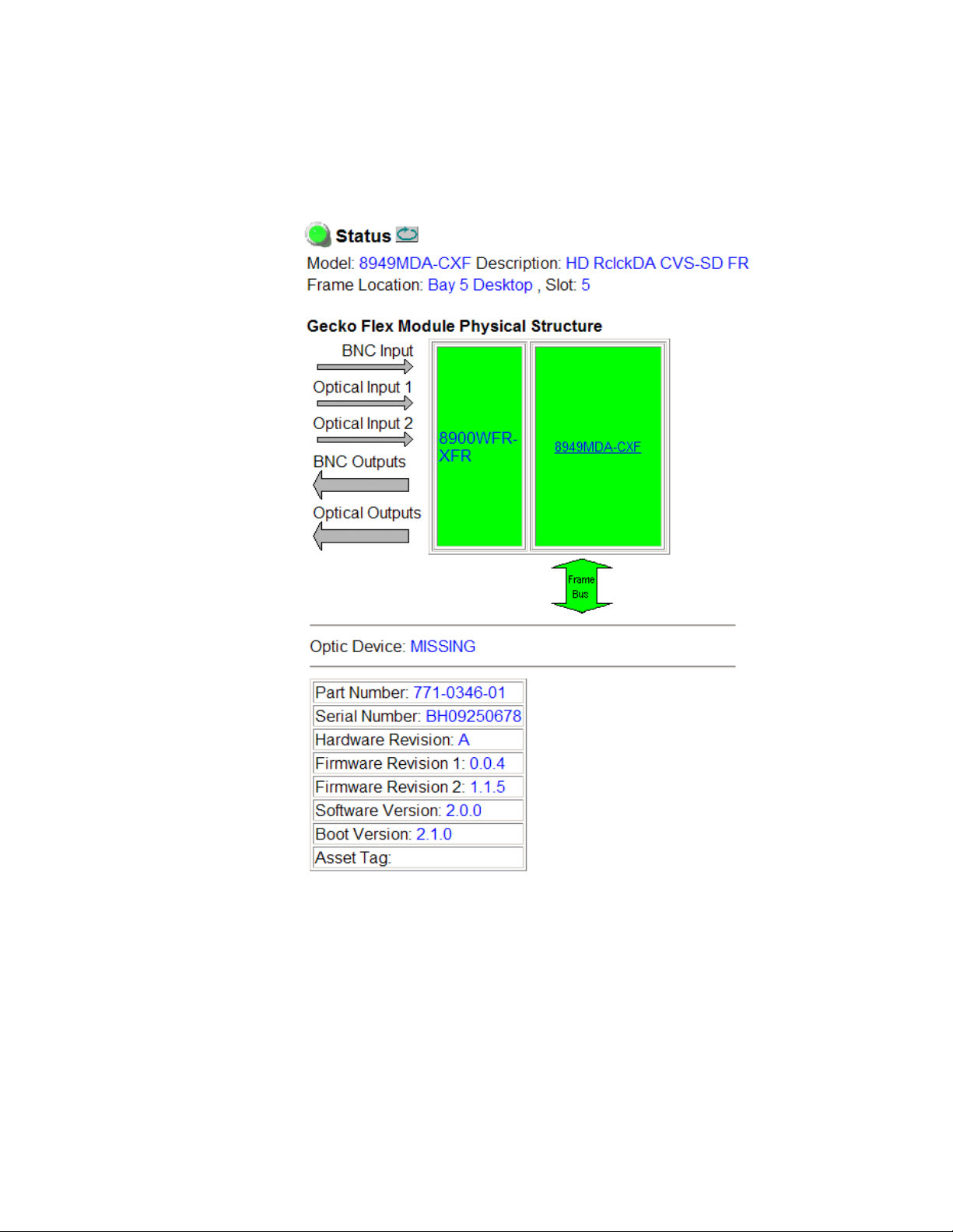
An 8949MDA-CXF Status web page without a fiber optic submodule
installed (
inputs are shown as not present.
Figure 18. Status Web Page for 8949MDA-CXF without Submodule
Figure 18) reports the Optic Device as Missing and the optical
8949MDA-CXF/-SXF — Instruction Manual 33
Page 34

Configuration
An 8949MDA Status web page with a Dual Receiver (DRL) submodule
installed (
(RX-RX 1310nm DRL).
Both the BNC Input and Optical Input 1 and 2 arrows will be active and
report the status of the input. One of the three inputs must be selected in
configuration as the active input.
Figure 19. Status Web Page for 8949MDA-CXF with DRL Submodule
Figure 19) reports the Optic Device as a dual receiver
34 8949MDA-CXF/-SXF — Instruction Manual
Page 35

Configuration
An 8949MDA Status web page with a Dual Transmitter (DTL) submodule
installed (
(TX-TX 1310nm DTL). Optic Input arrows are inactive.
The optional fiber optic outputs must be enabled in configuration. All BNC
and optional fiber optic outputs can be active at the same time.
Figure 20. Status Web Page for 8949MDA-CXF with DTL Submodule
Figure 20) reports the Optic Device as a dual transmitter
8949MDA-CXF/-SXF — Instruction Manual 35
Page 36

Configuration
An 8949MDA Status web page with a Transceiver (RTL) submodule
installed (
(TX-RX 1310nm TRL).
Optical Input 1 is active and reports the status of the fiber input. Either the
BNC or the fiber optic input can be active. This must be set in configuration.
The fiber output must be enabled in configuration.
Figure 21. Status Web Page for 8949MDA-CXF with TRL Submodule
Figure 21) reports the Optic Device as a Transceiver
36 8949MDA-CXF/-SXF — Instruction Manual
Page 37

Settings Web Page
Use
this
link
The Settings web page provides routing configuration of the available
video inputs, enabling of optional fiber optic outp
abling of status reporting, aspect ratio selection for the downscaled outputs, reporting of carrier detect status, and detected locked video input rate
and video format.
Note The 8949MDA-CXF also includes composite monitoring reporting status and
controls for enabling a color bars test signal and enabling and disabling of
setup on NTSC outputs.
The parameters for configuration of a 8949MDA module are explained in
detail below and in Figure 27 on page 41:
Routing Mode – input video selections in the Routing Mode control will
•
vary depending on the presence and type of fiber optic submodules
installed. This area can show up to three available video inputs. All
video inputs can be present, but only one video input can be configured
as active.
Configuration
uts, enabling and dis-
Coax In 1 J9 – the electrical input at BNC J9 will always be present.
•
When no fiber optic option is installed, the web page will appear as
shown in Figure 26 on page 40. It will default to the coax input.
Optic 1 (In) – this selection will be present when an Dual Receiver
•
(Figure 27 on page 41) or Transceiver fiber optic submodule is
installed (Figure 29 on page 43).
•
Optic 2 (In) – this selection will only appear when an Dual Receiver
fiber optic submodule is installed (Figure 27 on page 41).
Optic Outputs – this control, used to enable or disable fiber optic outputs,
•
will only be active when either a Dual Transmitter (Figure 28 on
page 42) or a Transceiver (Figure 29 on page 43) fiber optic submodule
is installed. All available fiber optic outputs can be enabled at the same
time. In addition, the four electrical outputs are always active, allowing
for a total of up to six possible outputs active at one time.
Input Reporting – choose between Enable or Disable signal status reporting
•
to the module level. When reporting has been disabled, the input
arrows will be grayed out to show they are not being monitored or
reported to the module level or upper level control devices.
Input Format – the video input format can be selected from the following
•
pulldown selections:
•Auto
• 1080i/50 or 59.94
• 720p/50 or 59.94
• 480i/59.94
• 576i/50
8949MDA-CXF/-SXF — Instruction Manual 37
Page 38

Configuration
Anamorphic on 4x3 Monitor
1080i on 16x9 Monitor
8563_04r0
Letterbox on 4x3 Monitor
1080i on 16x9 Monitor
8563_05r0
• Aspect Ratio– this pulldown allows selection of one of four aspect ratio
conversions on the downscaled HD electrical outputs. (This control has
no effect on SD downscaled outputs.):
Anamorphic – this mode converts a 16x9 HD image to a 4x3 SD image.
•
Shapes are not preserved causing them to stretch vertically as
shown in Figure 22.
Figure 22. Anamorphic Aspect Ratio
• Letterbox – this mode maintains a 16x9 SD image centered in the
middle three-quarters of the screen with black horizontal bars
above and below the picture. Shapes are preserved in this mode as
shown in Figure 23
Figure 23. .Letterbox Aspect Ratio
• 4x3 Center Cut – this mode is a 4x3 image that fills the screen, cutting
off one-quarter of the horizontal image and one-eighth of each side.
Shapes are preserved as shown in Figure 24.
Figure 24. 4x3 Center Cut Aspect Ratio
8563_06r0
1080i on 16x9 Monitor
4x3 Center Cut on 4x3 Monitor
38 8949MDA-CXF/-SXF — Instruction Manual
Page 39

Configuration
• 14x9 Center Cut – this mode allows a compromise between Letterbox
and 4x3 Center Cut. It cuts off one-eighth of the horizontal image,
one-sixteenth from each side and fits vertically in the middle 6/7 of
the screen with black horizontal bars above and below the picture.
Shapes are preserved.
Figure 25. 14x9 Center Cut Aspect Ratio
8563_07r0
1080i on 16x9 Monitor
14x9 Center Cut on 4x3 Monitor
• Carrier Detect – indicates the presence of valid input signal.
Locked Rate – this value is linked to the input bloodstream rate detected.
•
•
Video Format – this value reports the input video format detected.
Monitoring Format – this value indicates the downscaled output video
•
format.
Composite Color Bar – (8949MDA-CXF only) this parameter allows the
•
enabling and disabling of a composite color bar test pattern on the composite downscaled outputs.
Composite Setup – (8949MDA-CXF only) this parameter is shown if the
•
Monitoring Format is 480i/59.94. Configure as Setup or No Setup on the com-
posite outputs.
Note The composite controls will not be present on the 8949MDA-SXF Settings
web page as shown in the example in Figure 30 on page 44.
8949MDA-CXF/-SXF — Instruction Manual 39
Page 40

Configuration
Present on NTSC outputs only
Figure 26. Settings Web Page for 8949MDA-CXF without Submodule/NTSC Input
40 8949MDA-CXF/-SXF — Instruction Manual
Page 41

Figure 27. Settings Web Page for 8949MDA-CXF with DRL/576i Input
Dual Receiver provides
two optical inputs
PAL input has no setup
Configuration
8949MDA-CXF/-SXF — Instruction Manual 41
Page 42

Configuration
Dual Transmitter provides
two optical outputs
Figure 28. Settings Web Page for 8949MDA-CXF with DTL
42 8949MDA-CXF/-SXF — Instruction Manual
Page 43

Figure 29. Settings Web Page for 8949MDA-CXF with TRL
Transceiver provides
one optical input and
one optical output
Configuration
8949MDA-CXF/-SXF — Instruction Manual 43
Page 44

Configuration
No composite controls
Figure 30. Settings Web Page for 8949MDA-SXF without Submodule
44 8949MDA-CXF/-SXF — Instruction Manual
Page 45

Slot Config Web Page
Use
this
link
Use the Slot Config web page (Figure 31) to perform the following functions on the module. The Slot Config page is
•Locate Module
Slot Identification
•
•Slot Memory
• Frame Health Reports link
• LED Reports link
• SNMP Trap Reports link
Note This web page reflects an 8900NET module running version 4.3.0 in the
frame. Other 8900NET versions will vary in the appearance of this web page.
Figure 31. Slot Config Web Page
Configuration
the same for all modules:
8949MDA-CXF/-SXF — Instruction Manual 45
Page 46

Configuration
Locate Module
Selecting Flash from the Locate Module pulldown flashes the yellow COMM
and CONF LEDs on the front of the module so it can be located in the
frame.
Slot Identification
You may identify the module by typing a specific name in the Name field.
The assigned name is stored on the 8900NET module and travels with the
8900NET module if it is moved to another frame. Select
factory default module name.
An asset identification may be entered in the Asset Tag field. This will appear
on the module Status web page and in the NetConfig inventory report.
Default to enter the
Slot Memory
The slot configuration for each media module is automatically polled and
refreshed periodically (about every 50 minutes) by the 8900NET module
when the
page (with 4.3.0 software) and/or the
media module Slot Config web page is selected.
Always Slot Refresh checkbox on the 8900NET Configuration web
Restore upon Install checkbox on any
When the Restore upon Install checkbox on any media module Slot Config
web page has been selected, the current configuration from that module is
saved in slot memory on the 8900NET module. This allows the current
module to be removed and when another module of the same part number,
and software version is installed, the configuration saved to the 8900NET
module will be downloaded to the installed module. The
checkbox must be selected before the current module with the saved con
figuration is removed.
Note Make sure all modules of the same model type are running the same software
version and have the same part number silk-screened on the printed circuit
board. Downloading a configuration to a module with a different software
version or part number can produce unexpected results.
If a different type of module is installed in this slot, a warning message will
state that the original module type has been replaced with another module
type. In this case, a
configuration from the previous module.
You may also select the Learn Module Config button at any time to save the
current configuration for this slot. The configuration is saved on the
8900NET module. If the 8900NET module is removed or powered down,
the stored configurations are not saved.
Clear button will appear allowing you to clear the stored
Restore upon Install
-
46 8949MDA-CXF/-SXF — Instruction Manual
Page 47

Software Updating
When no Restore upon Install checkboxes on any of the media module Slot
Config web pages are selected and the
8900NET Configuration web page is unchecked, the slot refresh polling
function on the 8900NET module will be disabled. See the
checkbox description in the 8900NET (Net Card) Network Interface Module
Instruction Manual for more details.
Note Uncheck the Restore Upon Install button before downloading new software.
Always Slot Refresh checkbox on the
Always Slot Refresh
Frame Health Reporting
This web page allows configuration of the alarms and warnings that are
reported to the external Frame Health Alarm connector on the rear of the
GeckoFlex frame. Refer to 8900NET Instruction Manual for more details.
LED Reports
This link appears when the 8900NET module has software version 4.0.2 or
later installed. When the link is selected, a read-only status report of the
8900NET Hardware Switch state is given. In the LED Reporting section of
the web page, LED Reporting can be enabled or disabled as desired.
Software Updating
SNMP Trap Reports
Select the SNMP Trap Reports link to open the 8900NET SNMP Reporting
web page. this link will only be present when SNMP Agent software has
been installed on the 8900NET module. This web page allows configura
tion of which alarms and warnings that are reported to the SNMP management software.
Refer to 8900NET Instruction Manual for more details on the links to the
8900NET module.
Software updating of the 8949MDA modules is done using the NetConfig
Networking Application and other software update tools. The NetConfig
application is available free of charge from the Grass Valley web site. Check
the Grass Valley web site for update information. Refer to
Valley on page 4 for more information on obtaining the other required
update tools for this module.
All modular product documentation can be found in PDF format on the
Grass Valley web site at this link:
Contacting Grass
-
www.grassvalley.com/docs/modular
8949MDA-CXF/-SXF — Instruction Manual 47
Page 48

Status Monitoring
Status Monitoring
There are a number of ways to monitor frame and module status. These
methods are summarized here. For more detailed information, refer to the
8900NET (Net Card) Network Interface Module Instruction Manual and the
8900 Gecko or 8900 GeckoFlex Frame Instruction Manuals.
All modular product documentation is available on-line in PDF format at
this link:
www.grassvalley.com/docs/modular
The main status monitoring methods include the following:
• External frame alarm output on the rear of the 8900 frame with
• LEDs on the Frame, 8900NET module, and individual frame media
• Web browser status reporting for each frame component, and
reporting from the Module Health Bus and other frame status alarm
reports,
modules,
• SNMP traps, captured by Grass Valley’s NetCentral or another SNMP
Manager Application.
Note SNMP trap information is only available when an SNMP Agent has been
installed and configured.
External Frame Alarm
An external Frame Alarm output is available on pins 8 and 9 of the RS-232
connector on the rear of the frame. The Frame Alarm outputs a voltage
level indicating there is an alarm condition on the Module Health Bus or
one of the other frame components reported to the Frame Monitor module
in a Gecko 8900TF or GeckoFlex 8900FF frame or the 8900NET module in
an 8900TFN and GeckoFlex 8900FFN frame.
• The Module Health bus is a separate line on the frame motherboard
that provides a means for older or less capable modules (such as DAs
with no microprocessor) that cannot communicate over the Frame
(serial) bus to report warning and alarm conditions to the external
Frame Alarm. All media modules in the frame report a voltage level to
this line when a warning condition occurs on the module. The specific
warning or module location is not reported, only an indication that an
warning condition has occurred.
• Frame alarm reporting from other frame components can be enabled
and disabled using DIP switches on the Frame Monitor and 8900NET
module. For frames with an 8900NET module, the Frame Alarm
Reporting web page allows configuration of the alarms and warnings
that are reported to this external Frame Health Alarm.
48 8949MDA-CXF/-SXF — Instruction Manual
Page 49

LED Reporting
LEDs on the front of media modules, the Frame Monitor or 8900NET modules, and the front covers of the 8900TF/TFN and GeckoFlex FF/FFN
frames indicate status of the frame and the installed power supplies, fans
in the front covers, and module status. (The 8900TX-V/A and GeckoFlex
8900FX frames have no LED indicators on the front cover.)
• LED reporting from the modules in the frame to the 8900NET module
is configurable using the 8900NET LED Reporting web page.
• The Status LEDs for this module are described in Operation Indicator
LEDs on page 25. LEDs for the 8900NET module are described in the
8900NET (Net Card) Network Interface Instruction Manual.
Web Browser Interface
The 8900NET module controls a web browser GUI that indicates frame and
module status on the following web pages:
Status Monitoring
• Frame Status web page – reports overall frame and module status in
colored graphical and text formats. Refer to Figure 16 on page 29 for an
example.
•Module Status web page (Figure 18 on page 33) – shows specific input
and reference signal configuration error status to the module along
with module status and information (part number, serial number, hardware version, software/firmware/boot versions, and Asset number (as
assigned on the Slot Config web page).
• A Status LED icon on each web page reflects the module status on the
module Status web page where warnings and faults are displayed and
is a link to the module Status web page.
SNMP Reporting
The Gecko 8900 Series system uses the Simple Network Monitoring Protocol (SNMP) internet standard for reporting status information to remote
monitoring stations. When SNMP Agent software is installed on the
8900NET module, enabled status reports are sent to an SNMP Manager
such as the Grass Valley’s NetCentral application.
Status reporting for the frame is enabled or disabled with the configuration
DIP switches on the 8900NET module. Most module status reporting items
can be enabled or disabled on individual configuration web pages.
8949MDA-CXF/-SXF — Instruction Manual 49
Page 50

Specifications
Specifications
Table 5. 8949MDA-CXF and 8949MDA-SXF Specifications
Parameter Value
Coax Input
Number and type of inputs 1 BNC
Input impedance 75 Ohm
Input signal type Serial digital component conforming to the following formats:
• SMPTE 292M for 1080i/50, 1080i/59.94, 720p/50 and 720p/59.94
• SMPTE 259M (270 Mb/s)
Signal level SDI 800 mV p-p ±10% max
Return loss >15 dB 0.004 to 1.50 GHz
Equalization Auto equalizing:
HD signals up to 125m of Belden 1694A
SD signals up to 330m of Belden 1694A
Tolerated input jitter Compliant with the SMPTE 259M (270 Mb/s) and SMPTE 292M standards
Distributed Coax Outputs (both models)
Number and type of outputs 4 BNCs
Output impedance 75 Ohm
Signal type Serial digital component conforming to the following formats:
• 1080i/50, 1080i/59.94, 720p/50 and 720p/59.94
• SMPTE 259M (270 Mb/s)
Signal level SDI 800 mV p-p ±10%
Return loss >15 dB 4 to 270 MHz
>13 dB 0.27 to 1.50 GHz
Output jitter For input with < 0.1 UI jitter, the output jitter complies with the SMPTE
292M and SMPTE 259M standards
Downscaled Serial Outputs (8949MDA-SXF Module)
Number and type of outputs 4 BNCs
Impedance 75 ohm
Signal type Conforming to SMPTE 259M for 480i/59.94 and 576i/50
SDI level 800 mV±10%
Return loss > 15 dB
Output jitter Conforming to SMPTE 259M for 480i/59.94 and 576i/50
Downscaler delay < 0.95 ms
Downscaler output 10 bits representation
Output transcoding New EDH CRC packet generated on output
Downscaled Composite Outputs (8949MDA-CXF Module)
Number and type of outputs 4 BNCs
Impedance 75 ohm
Signal type Conforming to the SMPTE 170M standard for NTSC and
CCIR624 for PAL-B
Return loss > 40 dB, 0 to 10 MHz
Downscaler delay < 0.97 ms
Downscaler output 8 bits representation
50 8949MDA-CXF/-SXF — Instruction Manual
Page 51

Table 5. 8949MDA-CXF and 8949MDA-SXF Specifications
Parameter Value
Power
Maximum Input power
8949MDA-SXF 8.1W (without submodule), 8.8W (with submodule)
8949MDA-CXF 7.3W (without submodule), 8.0W (with submodule)
Environmental
Frame temperature range
(Refer to GeckoFlex Instruction Manual)
Operating humidity range
Non-operating temperature
MTBF at 40°C (inside the frame)
in hours with Tellcordia SR-332 Issue 1
8949MDA-CXF
8949MDA-SXF
UL and EU compliance When installed in a GeckoFlex frame
Mechanical
Frame type GeckoFlex 8900FFN
Number of slots required 1 slot
Rear module type required
8949MDA-CXF
8949MDA-SXF
Rear Retainer clip screw torque 4-5 inch-lb./0.45-0.6Nm
Refer to GeckoFlex Frames 8900FX/FF/FFN Signal Processing Systems
Instruction Manual at www.grassvalley.com/docs/modular
573,300
594,000
8900WFR-XFR
Specifications
Table 6. SFP Receiver/Transceiver Fiber Optic Submodule Specifications
Model Number SFP-13103G-M1DRX SFP-13103G-M1TRX
Low wavelength 1260nm 1260nm
High wavelength 1620nm 1620nm
Receiver channels 2 1
Connector type LC
Fiber support Single mode
Data rate 50Mb/s to 3Gb/s
Maximum distance @ 3Gb/s 10km
Minimum distance 30km
8949MDA-CXF/-SXF — Instruction Manual 51
Page 52

Specifications
Tab l e 7 . S F P Tr a ns m it te r /Tr a ns c ei v er Fiber Optic Submodule Specifications
Model Number SFP-13103G-M1DTX SFP-13103G-M1TRX
Wavelength 1 1310 nm 1310 nm
Wavelength 2 1310 nm N/A
Transmit channels 2 1
Connector type LC
Fiber support Single-mode
Data rate 143 Mb/s to 2.97 Gb/s
Power output -5 to 0 dBm (-2dBm typical)
Maximum distance 10 km
Maximum distance 20 km
1
The 1310 nm Dual Transmitter (SFP-13103G-M1DTX) and Transceiver (SFP-13103G-M1TRX) require no attenu-
ation between fiber transmitter and receiver connections at any length.
Attenuation Requirements
1
Some shorter length cable runs will require attenuation to prevent overdriving the receiver causing bit errors to occur on the fiber link. Use the following guidelines for adding attenuation:
• The Dual Transmitter requires no attenuation between fiber transmitter
and receiver connections at any cable lengths.
• All CWDM devices used in a point-to-point configuration with a cable
run from 0-20 km (12.4 miles), must be attenuated by 5 dB between
fiber transmitter and receiver connections.
• CWDM devices used with 8939FCA modules for a mux/demux configuration with a cable run from 0-12 km (7.5 miles), must be attenuated
by 3 dB between 8939CFA COM ports.
52 8949MDA-CXF/-SXF — Instruction Manual
Page 53

Service
Power-up Diagnostics Failure
Troubleshooting
The 8949MDA modules make extensive use of surface-mount technology
and programmed parts to achieve compact size and adherence to
demanding technical specifications. Circuit modules should not be ser
viced in the field unless otherwise directed by Customer Service.
If the module has not passed self-diagnostics, do not attempt to troubleshoot. Return the unit to Grass Valley (see Module Repair below).
Electronic Circuit Breaker
Service
-
The electronic circuit breaker works during a fault condition or an overcurrent which stops the module.
Remove the module and replace it in the frame. If the problem persists,
please refer to the Grass Valley Customer Service.
Module Repair
If the module is still not operating correctly, replace it with a known good
spare and return the faulty module to a designated Grass Valley repair
depot. Call your Grass Valley representative for depot location.
Refer to Contacting Grass Valley on page 4 at the front of this document for
information on contacting Grass Valley Customer Service.
8949MDA-CXF/-SXF — Instruction Manual 53
Page 54

Service
Table of Alarms
Ta bl e 8 below describes the different type of alarms that can occur on the
module.
Table 8. List of Alarms for 8949MDA module
Alarm
type
Fault Firmware failure If the firmware is wrong or after a bad download
Fault Optical failure Yes
Fault Optical submodule communication error communication problem with the optical module Yes
Fault Software/Firmware version incompatible Yes
Warning Signal not Present on BNC Input PRES COAX IN
Warning Wrong Rear Module The rear module is not compatible with the front module
Warning Signal not Present on Optic Input 1 PRES OPT IN 1
Warning Signal not Present on Optic Input 2 PRES OPT IN 2
Warning Mismatch or unknown format Format detected different of format selected or unknown
Warning Module not locked No
Warning Incoming bit stream error Video input signal have a bit stream error No
Web Page Description LED Comments
STATUS PAGE:
The color of the front module becomes red
(green)
(orange)
(orange)
STATUS PAGE:
The electrical input arrow is yellow
SETTING PAGE:
The carrier detect option is not present
8949MDA-CXF or 8949MDA-SXF
STATUS PAGE:
Optic input arrow is yellow
STATUS PAGE:
Optic input arrow is yellow
format detected
Net Card&SNMP
Query status
towards
Yes
Yes
Yes
Yes
Yes
No
54 8949MDA-CXF/-SXF — Instruction Manual
Page 55

Functional Description
HD/SD
SDI In
Equalizer and
Re-clocker
Down-
converter
Only one fiber
option may be
used
Fiber RX
Fiber RX
Fiber RX
Fiber TX
Fiber TX
Fiber TX
HD/SD
Optical In
HD/SD
Optical Out
Option
Option
Option
4X
HD/SD-SDI
Out
4X
SD-SDI
Out*
Auto
Format
Detection
*
Downscaled SD-SDI output transcoding includes only generation of new EDH CRC packet
Aspect Ratio
Control
A block diagram of the 8949MDA-CXF is shown in Figure 32.
Figure 32. 8949MDA-CXF Block Diagram
Functional Description
HD/SD
SDI In
HD/SD
Optical In
Equalizer and
Only one fiber
option may be
selected
Fiber RX
Fiber RX
Fiber RX
Re-clocker
Auto
Format
Detction
Option
Option
Aspect Ratio
Control
Down-
converter
Encoder
Option
A block diagram of the 8949MDA-SXF is shown in Figure 33.
Figure 33. 8929MDA-SXF Block Diagram
4X
HD/SD-SDI
Out
4X
PAL/NTSC
Out
Fiber TX
Fiber TX
HD/SD
Optical Out
Fiber TX
8949MDA-CXF/-SXF — Instruction Manual 55
Page 56

Functional Description
56 8949MDA-CXF/-SXF — Instruction Manual
Page 57

Configuration Summary Table
Ta bl e 9 provides a complete summary of the module functions and a com-
parison of the functionality available with each control type along with the
ranges and default values for each parameter and notes on each control.
Table 9. Summary of Configuration Functions
Local Controls
Switches
S1 and S2
S1: Pin 1
Off = Local Only
On = Local&Remote
S1: Pins 6 and 7
Input Select
Coax In: 0 0
Optic 1: 0 1, or
Optic 2: 1 0
S2: Pin 4
Off = Disabled
On = Enabled
N/A N/A
S1: Pins 2, 3, 4,5
Auto: 0 0 0 0
1080i/50: 0 0 0 1
1080i/59.94: 0 0 1 0
720p/50: 0 0 1 1
720p/59.94: 0 1 0 0
480i/59.94: 0 1 0 1
576i/50: 0 1 1 0
N/A AspRatio
N/A ColorBar
S1: Pin 8
Off = No Setup
On = Setup
Function
Type
Config mode Local&Remote
Routing mode
(Up to three inputs depending on
type of fiber optic submodule
installed.) Only one input can be
active at a time.
Optic outputs enable
(Up to two outputs depending on
type of fiber optic submodule
installed.) All fiber outputs can be
active at the same time.
Input reporting enable Enable Disable or Enable
Input Format selection Auto
Aspect Ratio control
(used only for HD downscaled
video)
Composite Color Bars test signal
(8949MDA-CXFonly)
Composite Setup
(8949MDA-CXF NTSC output only)
Default
Coax In J9
Disable Disable or Enable
Anamorphic
Disable Enable or Disable
Setup Setup or No Setup
Range/Choices
Resolution
Local or
Local&Remote
Coax In J9,
Optic 1 (In), or
Optic 2 (In)
Auto,
1080i/50,
1080i/5994
720p/50,
720p/59.94,
480i/59.94, or
576i/50
Anamorphic,
Letterbox,
4x3 Center Cut, or
14x9 Center Cut.
Web Page/
Function Name
Access to web pages can be locked
out only by Local controls
Settings/
Routing Mode
Coax In J9, Optic 1 (In), or
Optic 2 (In) radio button
Settings/
Optic Outputs pulldown
Settings/
Input Reporting pulldown
Settings/
Input Standard Selection
pulldown
Settings/
Aspect Ratio pulldown
Settings/
Composite Color Bar
pulldown
Settings/
Composite Setup pulldown
Newton
Control
Panel
N/A
Rout Mode
Optic Out
N/A
CompSetup
8949MDA-CXF/-SXF — Instruction Manual 57
Page 58

Configuration Summary Table
58 8949MDA-CXF/-SXF — Instruction Manual
Page 59

Index
Numerics
14x9 Center Cut aspect ratio 39
4x3 Center Cut aspect ratio 38
8900NET (Net Card) module 10, 29
A
anamorphic aspect ratio 38
aspect ratio 38
attenuation requirements 52
Auto cable equalization 10
B
block diagram 55
C
cabling
overview
Carrier Detect reporting 39
Clear button 46
Coarse adjust button
overview
Coax In 1 J9 37
coaxial inputs 37
color bars
on 8949MDA-CXF outputs
COMM LED 26
Composite Color Bar test pattern 39
Composite Setup
local configuration
remote configuration 39
COMPOSITE SETUP LED 26
CONF (configuring) LED 26
configuration
local controls
summary table 57
control panel 27
21
30
12
11
9
D
documentation online 4
downscaled composite outputs
specifications
downscaled outputs
8949MDA-CXF
8949MDA-SXF 9, 22
downscaled serial outputs
specifications
50
9, 22
50
F
factory defaults
summary table
FACTORY LED 26
FAQ database 4
FAULT LED 26
features 10
fiber optic cleaning kit 17
fiber optic inputs
cabling
selecting 37
fiber optic outputs
cabling
enabling and disabling 37
fiber optic submodule options 16
installation 18
list of model numbers 16
overview 16
Fine adjust button
overview
Frame Health Reporting 47
Frame Status web page 29, 49
frequently asked questions 4
front module
installation
23
23
57
30
20
G
GeckoFlex frame
8949MDA-CXF/-SXF — Instruction Manual 59
Page 60

Index
frame alarm 48
graphical user interface (GUI) 31
Grass Valley web site 4
I
Input Format selection 37
Input power 51
input reporting
enabling and disabling
input routing mode 37
installation
front module
overview 11
precautions 14
rear module 15
Internet Explorer 29
20
37
L
LEDs
front edge illustration
overview 26
Letterbox aspect ratio 38
Locate Module function 46
Locked rate reporting 39
25
O
online documentation 4
operating system 29
P
power specifications 51
PRES OPT MOD LED 26
PRES SIG EQ LED 26
PRES SIG OPT 1 LED 26
PRES SIG OPT 2 LED 26
PWR LED 25, 26
R
rear module
installation
installation precautions 14
maximum screw torque specification 15
rear retainer clip
screw torque specification
Refresh button 30
Remote control 10
Restore upon Install checkbox 46
retainer clip tool 15
15
15, 51
M
Module Health Bus 48
module installation precautions 14
Module Status web page 49
Monitoring Format of downscaled output 39
MONITORING MODE LEDs 26
mounting bracket
SFP fiber optic submodule
17
N
NetConfig PC application
required for updating software
Newton Control Panel
overview
summary table of controls 57
60 8949MDA-CXF/-SXF — Instruction Manual
27
47
S
Settings web page 37
setup
on 8949MDA-CXF outputs
SIG_PRES LED 25
Slot Config web page 45
slot memory 46
SNMP reporting
enabling SNMP Trap Reports
overview 49
software download from web 4
software updating 47
specifications
all modules and fiber optic submodules
Status LED icon 30
status monitoring
overview
Status web page 32
48
9
47
50
Page 61

V
Video Format reporting 39
video input 21
video input(s)
specifications
video outputs
specifications
50
50
W
web browser
overview
recommended 29
web site
documentation
FAQ database 4
Grass Valley 4
software download 4
28
4
Index
8949MDA-CXF/-SXF — Instruction Manual 61
Page 62

Index
62 8949MDA-CXF/-SXF — Instruction Manual
 Loading...