

Page 1
8949MDA-CFR/-SFR
HD MONITORING DA MODULE
Instruction Manual
SOFTWARE VERSION 1.0.X AND 2.0.X
071843401
JULY 2006
Page 2

Contacting Grass Valley
Call Centers
Two international Contact Centers (US and France) can be reached 24 hours
a day, 7 days a week:
From the US: Call 1-800-547-8949 or (530) 478-4148
From other countries: Call +800 80 80 20 20 or +33 1 48 25 20 20
For your local Support Contact, please refer to www.thomsongrass-
valley.com/support/phone.
Grass Valley Web Site
The Web Site www.thomsongrassvalley.com offers the following:
Online User Documentation - Current versions of product catalogs,
brochures, data sheets, ordering guides, planning guides, manuals ans
release notes in .pdf format can be downloaded on www.thomson-
grassvalley.com/docs/.
FAQ Database - Solutions to problems and troubleshooting efforts can
be found our Frequency Asked Questions (FAQ) database on
www.thomsongrassvalley.com/support/ choose Troubleshooting/
FAQ
Software downloads - Software updates, drivers and patches can be
downloaded on www.thomsongrassvalley.com/support/ choose Trou -
bleshooting/FAQ and make a search.
Warranty registration - Use our convenient on-line registration on
www.thomsongrassvalley.com/ProdReg for product warranty regis-
tration.
Copyright © Grass Valley. All rights reserved.
This product may be covered by one or more U.S. and foreign patents.
2 8949MDA-CFR and 8949MDA-SFR Instruction Manual
Page 3

Contents
Preface. . . . . . . . . . . . . . . . . . . . . . . . . . . . . . . . . . . . . . . . . . . . . . . . . . . . . . . . . . . . . . . . . . . . . 5
About This Manual . . . . . . . . . . . . . . . . . . . . . . . . . . . . . . . . . . . . . . . . . . . . . . . . . . . . . 5
8949MDA-CFR and 8949MDA-SFR . . . . . . . . . . . . . . . . . . . . . . . . . . . . . . . . . . . . . . 7
Introduction . . . . . . . . . . . . . . . . . . . . . . . . . . . . . . . . . . . . . . . . . . . . . . . . . . . . . . . . . . . 7
Features . . . . . . . . . . . . . . . . . . . . . . . . . . . . . . . . . . . . . . . . . . . . . . . . . . . . . . . . . . . . . 7
Product Architecture. . . . . . . . . . . . . . . . . . . . . . . . . . . . . . . . . . . . . . . . . . . . . . . . . . 8
Product Environment . . . . . . . . . . . . . . . . . . . . . . . . . . . . . . . . . . . . . . . . . . . . . . . . . 9
Software Version Requirement . . . . . . . . . . . . . . . . . . . . . . . . . . . . . . . . . . . . . . . . . 9
Installation . . . . . . . . . . . . . . . . . . . . . . . . . . . . . . . . . . . . . . . . . . . . . . . . . . . . . . . . . . . 10
Local Configuration . . . . . . . . . . . . . . . . . . . . . . . . . . . . . . . . . . . . . . . . . . . . . . . . . 10
Module Placement in the GeckoFlex Frame . . . . . . . . . . . . . . . . . . . . . . . . . . . . . 11
Rear Module Installation . . . . . . . . . . . . . . . . . . . . . . . . . . . . . . . . . . . . . . . . . . . 11
Front Module Installation. . . . . . . . . . . . . . . . . . . . . . . . . . . . . . . . . . . . . . . . . . . 12
Optional Fiber Optic Submodule. . . . . . . . . . . . . . . . . . . . . . . . . . . . . . . . . . . . . 12
Cabling . . . . . . . . . . . . . . . . . . . . . . . . . . . . . . . . . . . . . . . . . . . . . . . . . . . . . . . . . . . . . . 14
Power Up . . . . . . . . . . . . . . . . . . . . . . . . . . . . . . . . . . . . . . . . . . . . . . . . . . . . . . . . . . . . 16
Operation Indicator LEDs . . . . . . . . . . . . . . . . . . . . . . . . . . . . . . . . . . . . . . . . . . . . 16
Remote Configuration . . . . . . . . . . . . . . . . . . . . . . . . . . . . . . . . . . . . . . . . . . . . . . . . . 18
8900NET Module Information. . . . . . . . . . . . . . . . . . . . . . . . . . . . . . . . . . . . . . . . . 18
Newton Control Panel Configuration . . . . . . . . . . . . . . . . . . . . . . . . . . . . . . . . . . 18
Web Browser Interface . . . . . . . . . . . . . . . . . . . . . . . . . . . . . . . . . . . . . . . . . . . . . . . 19
8949MDA-CFR and 8949MDA-SFR Links and Web Pages . . . . . . . . . . . . . . . . . 21
Status Web Page. . . . . . . . . . . . . . . . . . . . . . . . . . . . . . . . . . . . . . . . . . . . . . . . . . . 21
Settings Web Page . . . . . . . . . . . . . . . . . . . . . . . . . . . . . . . . . . . . . . . . . . . . . . . . . 23
Slot Config Web Page . . . . . . . . . . . . . . . . . . . . . . . . . . . . . . . . . . . . . . . . . . . . . . 25
Specifications . . . . . . . . . . . . . . . . . . . . . . . . . . . . . . . . . . . . . . . . . . . . . . . . . . . . . . . . . 27
Service. . . . . . . . . . . . . . . . . . . . . . . . . . . . . . . . . . . . . . . . . . . . . . . . . . . . . . . . . . . . . . . 29
Power-up Diagnostics Failure . . . . . . . . . . . . . . . . . . . . . . . . . . . . . . . . . . . . . . . . . 29
Troubleshooting. . . . . . . . . . . . . . . . . . . . . . . . . . . . . . . . . . . . . . . . . . . . . . . . . . . . . 29
The Electronic Circuit Breaker . . . . . . . . . . . . . . . . . . . . . . . . . . . . . . . . . . . . . . . 29
Table of Alarms . . . . . . . . . . . . . . . . . . . . . . . . . . . . . . . . . . . . . . . . . . . . . . . . . . . 30
Module Repair . . . . . . . . . . . . . . . . . . . . . . . . . . . . . . . . . . . . . . . . . . . . . . . . . . . . . . 30
Functional Description . . . . . . . . . . . . . . . . . . . . . . . . . . . . . . . . . . . . . . . . . . . . . . . . . 31
Input Processing . . . . . . . . . . . . . . . . . . . . . . . . . . . . . . . . . . . . . . . . . . . . . . . . . . . . 31
Reclocking Processing. . . . . . . . . . . . . . . . . . . . . . . . . . . . . . . . . . . . . . . . . . . . . . . . 31
HD to SD Downscaling. . . . . . . . . . . . . . . . . . . . . . . . . . . . . . . . . . . . . . . . . . . . . . . 31
Output Processing . . . . . . . . . . . . . . . . . . . . . . . . . . . . . . . . . . . . . . . . . . . . . . . . . . . 32
Microprocessor. . . . . . . . . . . . . . . . . . . . . . . . . . . . . . . . . . . . . . . . . . . . . . . . . . . . . . 32
Power Supply. . . . . . . . . . . . . . . . . . . . . . . . . . . . . . . . . . . . . . . . . . . . . . . . . . . . . . . 32
Index . . . . . . . . . . . . . . . . . . . . . . . . . . . . . . . . . . . . . . . . . . . . . . . . . . . . . . . . . . . . . . . . . . . . . . 33
8949MDA-CFR and 8949MDA-SFR Instruction Manual 3
Page 4

Contents
4 8949MDA-CFR and 8949MDA-SFR Instruction Manual
Page 5

Preface
About This Manual
This manual describes the features of 8949MDA-CFR and 8949MDA-SFR front
modules, their corresponding rear module (8900WFR-R), the optical submodules
1310NM-DRL (Dual Receiver Fiber Optic), 1310NM-DTL (Dual Transmitter
Fiber Optic) and 1310NM-TRL (Transceiver Fiber Optic) in the GeckoFlex frame.
As part of this module family, it is subject to Safety and Regulatory Compliance
described in the GeckoFlex frame documentation.
8949MDA-CFR and 8949MDA-SFR Instruction Manual 5
Page 6

Preface
6 8949MDA-CFR and 8949MDA-SFR Instruction Manual
Page 7

8949MDA-CFR and 8949MDA-SFR
Introduction
The 8949MDA-CFR or 8949MDA-SFR performs HD/SD equalization, and
reclocking for distribution of HD/SD signals among electrical connectors and/or a
fiber optic submodule and downscaling of HD video signals to SD video signals
for monitoring applications among electrical connectors.
The two models, 8949MDA-CFR (composite downscaler outputs) and
8949MDA-SFR (serial data interface downscaler outputs) must be installed in a
GeckoFlex frame.
Features
The 8949MDA module features include:
• Multi-format HD or SD on one electrical input or optical inputs,
• In HD mode for inputs:
• Up to four reclocked HD electrical outputs and up to two reclocked HD
optical outputs,
• Up to four downscaled HD to SD (SDI signals in the case of
8949MDA-SFR or composite signals in the case of 8949MDA-CFR) electrical outputs,
• In SD mode for inputs:
• Up to eight reclocked SD (SDI standard) electrical outputs and up to two
reclocked SD optical outputs in the case of 8949MDA-SFR,
• Up to four reclocked SDI outputs and up to two reclocked SD optical
outputs and up to four composite outputs in the case of 8949MDA-CFR,
• Auto cable equalization for up to 330m of cable in the case of SD signals and
for up to 125m of cable in the case of HD signals,
• A range of standard definition or high definition input signal on one electrical
input or optical inputs,
• Downscaled signals with monitoring quality,
8949MDA-CFR and 8949MDA-SFR Instruction Manual 7
Page 8
Introduction
s
Product Architecture
• Alarm (signal presence detection) and status management,
• SNMP MIB reporting basic board alarms,
• A fiber optic submodule option providing optical input/output interfaces for all
models. One of the three different types of single-mode fiber optic submodules
can be used:
1
• 1310NM-DRL
- provides two optical inputs (RX1 and RX2),
• 1310NM-DTL - provides two optical outputs (TX1 and TX2),
• 1310NM-TRL - provides one optical input (RX1) and one optical output
(TX1), and
• Remote control and monitoring support: web pages, Newton control panel,
NetConfig management system.
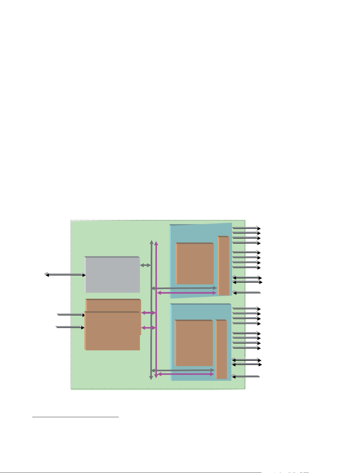
The 8949MDA-CFR and 8949MDA-SFR can only be installed in the GeckoFlex
frame illustrated in Figure 1 below.
Ethernet
100 - 240 Volts
Figure 1. Product Architecture
GeckoFlexhousing
(8900FFN)
8900NET
Network Interface Module
Power Supply
Power Supply
(8900F-PSX)
Frame
Bus
±12V
Gecko HD DA
(8949MDA-CFR)
Front Module
Gecko HD DA
(8949MDA-SFR)
Front Module
Reclocked
SD/HD
8
9
0
0
W
F
R
R
on electrical outputs
Composite downscaled
signals on electrical
outputs
Reclocked SD/HD on
Fiber Optic Submodule
SD/HD
Reclocked
SD/HD
on electrical outputs
8
9
0
0
W
F
R
R
SDI downscaled signals
on electrical outputs
Reclocked SD/HD on
Fiber Optic Submodules
SD/HD
8434-01
1.
Please contact your Grass Valley representative for ordering this option (1310NM-DRL)
8 8949MDA-CFR and 8949MDA-SFR Instruction Manual
Page 9

Product Environment
The 8949MDA-CFR and 8949MDA-SFR modules can only be installed in a GeckoFlex frame (8900FF, 8900FX and 8900FFN). The devices can be located in
broadcast centers, video production facilities, OB vans and production trucks. The
main application of those products is the jitter reduction, the distribution of the
incoming SD or HD signals to the video processing devices (routers, switchers,
tape recorder, monitoring devices, etc.) and the downscaling of HD video signals
to SD or composite video signals for monitoring applications.
Software Version Requirement
This manual covers two software versions. It is important to distinguish the board
version (hardware implementation) related to the software version.
Table 1. Hardware/Software Compatibility
Introduction
Model
8949MDA-CFR 671-6708-10 671-6708-11 771-0283-10
8949MDA-SFR 671-6708-20 671-6708-21 771-0283-20
Note The part number is given on the Status web page if the 8900NET module is
present. And it is written on the module.
Board Part Number
from 1.0.6 Version
Board Part Number
from 2.0.2 Version
Board Part Number
from 2.0.4 Version
8949MDA-CFR and 8949MDA-SFR Instruction Manual 9
Page 10
Installation
Installation
Local Configuration
The front and the rear modules (Cabling on page 14) are delivered together as a set.
The 8949MDA-CFR and 8949MDA-SFR front modules can be plugged in and
removed from a GeckoFlex frame with power on, without disrupting operation on
adjacent running modules. When power is applied to the module, LED indicators
reflect the initialization process (see Power Up on page 16).
CAUTION It is advised to take precautions for the installation and the removal
of the optional fiber optic submodule, see Optional Fiber Optic Submodule on page 12.
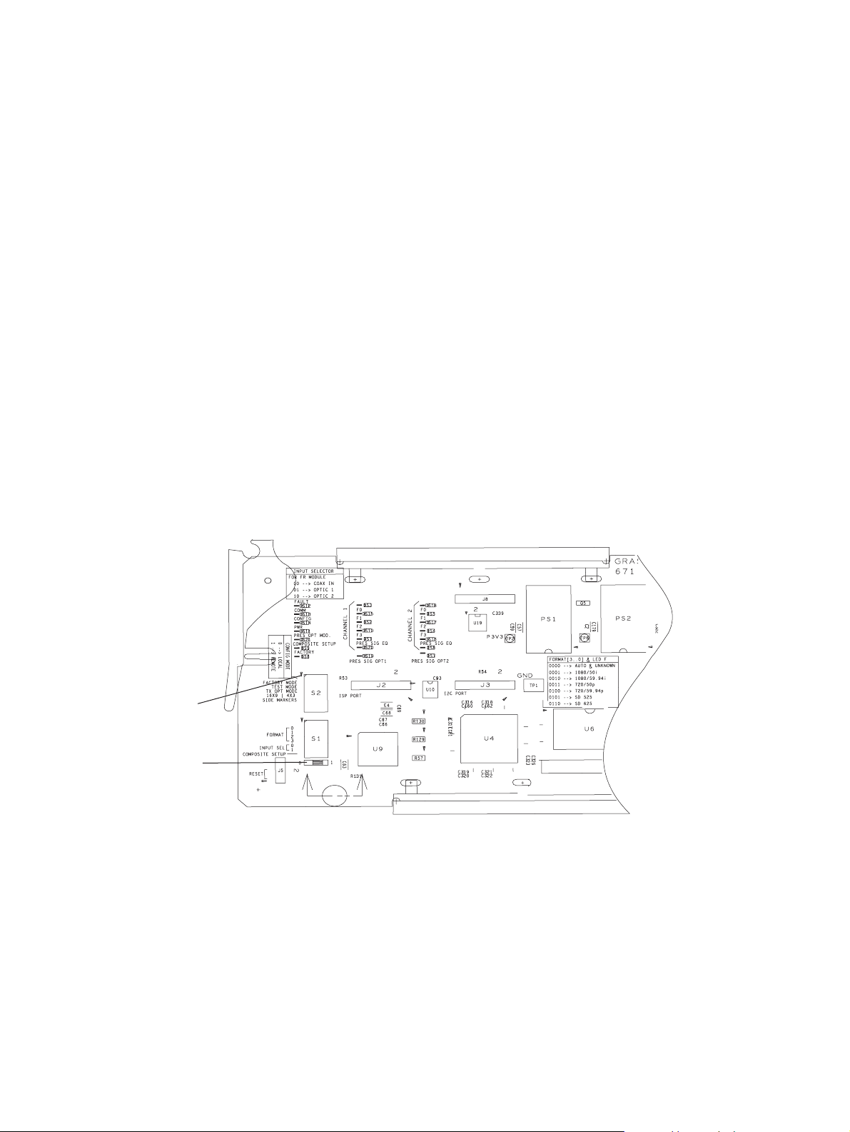
Local configuration of the 8949MDA-CFR and 8949MDA-SFR consists of several
switches (S1 and S2 blocks) as shown in Figure 2.
If you do not have an 8900NET module, you will need to configure the module
using the local onboard controls before installing the front module.
Config mode
Switch position
Figure 2. Switches on 8949MDA Module
8434-02
10 8949MDA-CFR and 8949MDA-SFR Instruction Manual
Page 11

Installation
Table 2 gives the parameter to be set with the onboard switches of the 8949MDA
modules.
Table 2. Switch S1 and S2 Positions
Position 0 1
CONFIG MODE Local mode: the other switches must
FACTORY MODE OFF For maintenance only
TEST MODE OFF For maintenance only
TX OPT MODE OFF ON (enables the transmission through
16X9 I 4X3 UNUSED
SIDE MARKERS UNUSED
FORMAT Selection of the incoming format:
INPUT SEL
coax in
optic 1
optic 2
COMPOSITE SETUP OFF ON
be manually positioned
Selection of the input connectors:
Remote mode: the other parameters
wil be positioned by the web pages
via the NetConfig application
the fiber optic submodule)
0000 = AUTO
0001 = 1080I/50
0010 = 1080I/59.94
0011 = 720p/50
0100 = 720p/59.94
0101 = 480i/59.94
0110 = 576i/50
00
01
10
Module Placement in the GeckoFlex Frame
There are ten rear and front slot locations in the 2 RU frame to accommodate either
analog or digital modules. The 8949MDA-CFR or 8949MDA-SFR module can be
plugged into any one of the GeckoFlex frame slots.
Note As the module can be changed when the GeckoFlex is powered on,
before removing the cover, please put an anti-static bracelet tied to a
metal part of the frame.
Rear Module Installation
Note Never completely remove the screws which maintain the retainer strips.
To install a rear module into the frame, follow these steps:
1. Unscrew the blank rear adapter cover without removing the screws, see
Figure 3.
2. Remove the two retainer strips and the blank rear adapter cover using a
needlenose plier.
8949MDA-CFR and 8949MDA-SFR Instruction Manual 11
Page 12

Installation
3. Insert the corresponding rear module in the slot.
4. Replace both retainer strips on each side of the rear module and tighten the
screws to secure the rear module.
Figure 3. Back Panel
8434-03
Note To extract the rear module, do not forget to extract the front module first.
Front Module Installation
Note Before installing the front module, the rear module must be already placed.
Please refer to the Optional Fiber Optic Submodule below, if the fiber optic
submodule is present.
After installing the rear module:
1. Unscrew and remove the front cover.
2. Insert the front module in the guides of the corresponding slot.
3. The module ejector tab (Figure 4) must be locked in its locking pin.
Figure 4. Module Ejector Tab Locking Pin
Ejector
Tab
Locking Pin
8434 -04
Optional Fiber Optic Submodule
When the fiber optic submodule is present, it is advised to take some precautions
so as not damage the modules.
12 8949MDA-CFR and 8949MDA-SFR Instruction Manual
Page 13

Installation
To install the fiber optic submodule:
1. Install the rear module, refer to Rear Module Installation on page 11.
2. Install the front module, refer to Front Module Installation on page 12.
3. Slide the fiber optic submodule into the cage connector (the label on the right).
Figure 5. Fiber Optic Submodule
J7J9J8
FIBER
Label
Fiber 2
Fiber 1
Arrow Indicators:
Handle
1310-DRL
1310-DTL
8434_05
1310-TRL
4. Before inserting the fiber cable, it is important to clean it with alcohol and a
lint-free filter paper.
The fiber optic submodule is hot-pluggable and may be installed or removed with
power applied to the front module.
The module type is identified by name on the label or can be identified by the direction of the two arrow indicators on the label.
Note When installed properly, the front end of the submodule will line up with the
BNCs. Do not try to force it in further.
To extract the fiber optic submodule follow the steps:
Note The fiber cable and the fiber optic submodule must be extracted before the
front and the rear modules.
1. Remove the fiber cable first.
8949MDA-CFR and 8949MDA-SFR Instruction Manual 13
Page 14

Cabling
Cabling
2. Unlock the module by flipping the handle to the left.
3. Remove the fiber optic submodule by using its handle.
Cabling to the 8949MDA-CFR or 8949MDA-SFR module is done on the BNCs
and the fiber connector on the rear module. Refer to Figure 5 on page 13 for the
fiber optic cabling and Figure 6 on page 15 for a detailed illustration of the rear
connections referenced below. Cabling of the rear module depends on what fiber
optic submodule option is installed as below:
• 8949MDA-CFR/-SFR without fiber optic submodule option (electrical only),
• 8949MDA-CFR/-SFR with 1310NM-DRL (Dual Receiver Fiber Optic)
• 8949MDA-CFR/-SFR with 1310NM-DTL (Dual Transmitter Fiber Optic),
and
• 8949MDA-CFR/-SFR with 1310NM-TRL (Transceiver Fiber Optic).
The 8949MDA-CFR or 8949MDA-SFR will accept any of the video standards
listed in the input specifications in Table 6 on page 27.
Connect a video input to BNC J9 or Fiber.
The 8949MDA-CFR or 8949MDA-SFR outputs conform to the video standards
listed in the output specifications in Table 6 on page 27.
Table 3 below and Table 4 on page 15 gives the inputs and the possible video
output connections for the 8949MDA modules in Figure 5 on page 13.
Table 3. Cabling Inputs and Outputs for 8949MDA-SFR Module
Fiber Optic Submodule Inputs in HD Outputs
Dual receiver J9
or Fiber 1
or Fiber 2
Dual transmitter J9 J1, J3, J5, J7: 4 HD electrical outputs
Tr an sceiver J9
or Fiber 1
J1, J3, J5, J7: 4 HD-SDI outputs
J2, J4, J6, J8: 4 downscaled SD-SDI
outputs
Fiber 1 and Fiber 2: 2 optical HD outputs
J2, J4, J6, J8: 4 downscaled SD-SDI
outputs
J1, J3, J5, J7: 4 HD electrical outputs
Fiber 2: 1 optical HD outputs
J2, J4, J6, J8: 4 downscaled SD-SDI
outputs
14 8949MDA-CFR and 8949MDA-SFR Instruction Manual
Page 15

Table 4. Cabling Inputs and Outputs for 8949MDA-CFR Module
8900WFR-R
J1 J2
8434-06
Fiber 1
Fiber 2
Fiber Optic Submodule Inputs in HD Outputs
Dual receiver J9
or Fiber 1
or Fiber 2
Dual transmitter J9 J1, J3, J5, J7: 4 HD electrical outputs
Tr an sceiver J9
or Fiber 1
Figure 6. 8949MDA rear Module
J1, J3, J5, J7: 4 HD-SDI outputs
J2, J4, J6, J8: 4 downscaled composite
video outputs
Fiber 1 and Fiber 2: 2 optical HD outputs
J2, J4, J6, J8: 4 downscaled composite
video outputs
J1, J3, J5, J7: 4 HD electrical outputs
Fiber 2: 1 optical HD outputs
J2, J4, J6, J8: 4 downscaled composite
video outputs
Cabling
8435-07
8949MDA-CFR and 8949MDA-SFR Instruction Manual 15
Page 16

Power Up
Power Up
Operation Indicator LEDs
The on-board LED indicators are illustrated in Figure 7. Upon power-up, the green
PWR LED should light and the CONFIG, FAULT and COMM LEDs should illuminate during the module initialization.
Note When a module is first plugged into a GeckoFlex frame, the 8900NET module
(if present) may report a momentary fault. This will clear once the module has
booted up.
With a valid input signal connected, PRES SIG LED (EQ in channel 1, OPT1,
OPT2) should be on. Refer to Table 5 on page 17 to see a complete list of possible
operating conditions and the resulting indicator status.
Figure 7. LEDs Significations - Part of the 8949MDA-CFR or 8949MDA-SFR module
Note The channel 2 LEDs are not connected.
16 8949MDA-CFR and 8949MDA-SFR Instruction Manual
Page 17

A red FAULT LED indicates an error situation and, when noted with the other indicator LEDs, can indicate a specific problem area. Tab le 5 describes signal output
and LED indications for the various input/reference combinations.
Table 5. LED Indicators
LED Indication Condition
FAULT (red)
COMM (yellow)
CONFIG (yellow)
PWR (green)
PRES OPT MOD
(yellow)
COMPOSITE SETUP
(yellow)
FACTORY
(yellow)
MONITORING MODE
(Channel 1
F0, F1, F2 and F3)
(yellow)
PRES SIG EQ
(green)
PRES SIG OPT 1
(green)
PRES SIG OPT 2
(green)
Off Normal operation
On continuously Module has detected internal fault
Off No activity on frame communication bus
Long flashLocation Command received by the module from a remote control system
Short flashActivity present on the frame communication bus
Off Module is in normal operating mode
On continuously Module is initializing, changing operating modes or updating firmware
Off No power to module or module’s DC/DC converter failed
On continuously Normal operation, module is powered
Off Fiber optic submodule not installed
On Fiber optic submodule installed
Off Setup disabled
On Setup enabled
Off Normal operation
On Test mode or factory mode
0000 --> Auto
0001 --> 1080i/50
0010 --> 1080i/59.94
0011 --> 720p/50
0100 --> 720p/59.94
0101 --> 480i/59.94
0110 --> 576i/50
Off No presence of signal on BNC (on J9 connector)
On continuously Presence of signal on BNC (on J9 connector)
Off No presence of optical signal on opt 1
On continuously Presence of optical signal on opt1
Off No presence of optical signal on opt 2
On continuously Presence of optical signal on opt 2
Power Up
8949MDA-CFR and 8949MDA-SFR Instruction Manual 17
Page 18

Remote Configuration
Remote Configuration
The 8949MDA-CFR/8949MDA-SFR configuration and monitoring can be also
performed using a web browser GUI interface or a networked Newton Control
Panel when the 8900NET Network Interface module is present in the GeckoFlex
frame (8900FFN). Each of these interfaces is described below.
8900NET Module Information
Refer to the 8900NET Network Interface Module Instruction Manual from 4.0
version for information on the 8900NET Network Interface Module and setting up
and operating the GeckoFlex 8900 frame network.
Note Upgrade software and instructions for the 8900NET can be downloaded from
the Grass Valley web site.
Newton Control Panel Configuration
A Newton Control Panel (hard or soft version) can be interfaced to the GeckoFlex
frame over the local network. Refer to the documentation that accompanies the
Newton Modular Control System for installation, configuration, and operation
information.
Control panel access offers the following considerations for module configuration
and monitoring:
• Ability to separate system level tasks from operation ones, minimizing the
potential for on-air mistakes.
• Ability to group modular products—regardless of their physical locations—into logical groups (channels) that you can easily manipulate with
user-configured knobs.
• Update software for applicable modules and assign frame and panel IP
addresses with the NetConfig Networking application.
• Recommended for real-time control of module configuration parameters, providing the fastest response time.
Note Not all module functions are available with the control panel, such as factory
default recalls.
18 8949MDA-CFR and 8949MDA-SFR Instruction Manual
Page 19

Remote Configuration
An example of the Newton Configurator is shown in Figure 8.
Figure 8. Newton Configurator Example
Web Browser Interface
The web browser interface provides a graphical representation of module configuration and monitoring.
Use of the web interface offers the following considerations:
• Web access will require some normal network time delays for processing of
information.
• Configuration parameter changes may require pressing
upload processing time,
• Web interface recommended for setting up module signal and slot names, and
reporting status for SNMP and monitoring.
Refer to the Status web page shown in Figure 9 on page 20. The 8900 modules can
be addressed by clicking either on a specific module icon in the frame status
display or on a module name or slot number in the link list on the left.
Apply button or Enter,
and a manual screen refresh to become effective.
8949MDA-CFR and 8949MDA-SFR Instruction Manual 19
Page 20

Remote Configuration
The link section lists the frame and its current modules. The selected link’s Status page is first displayed and the
sub-list of links for the selection is opened. The sub-list allows you to select a particular information page for the
selected device.
In general, graphics and text colors used indicate the following:
• Green = Pass – signal or reference present, no problems detected.
• Red = Fault – fault condition.
• Yellow = Warning – signal is absent, has errors, or is mis-configured.
• Gray = Not monitored.
• White = Not present.
Note The physical appearance of the graphics on the web pages shown in this
manual represent the use of a particular platform, browser and version of
8900NET module software. They are provided for reference only. Web pages
will differ depending on the type of platform and browser you are using and
the version of the 8900NET software installed in your system. The GeckoFlex
frames works with 8900NET module from 4.0 version.
• For information on status and fault monitoring and reporting shown on the
Status page, refer to Status Web Page on page 21.
Figure 9. Main Menu
Content display section displays the information page for the selected frame or module
(frame slot icons are also active links).
Refresh button for manual update of page
20 8949MDA-CFR and 8949MDA-SFR Instruction Manual
Page 21

Remote Configuration
Note Refresh button must be clicked to update the page after any changes.
8949MDA-CFR and 8949MDA-SFR Links and Web Pages
The 8900 GUI provides the following links and web pages for the 8949MDA-CFR
and 8949MDA-SFR modules (Figure 10 below):
• Status – reports input and output signals and frame bus communication status
and module information (below),
• Settings – allows the configuration of the inputs and outputs (page 23),
• Slot Config – provides the slot identification, the memory slot and the reports
for the frame health and the SNMP trap (page 25).
The 8949MDA modules can use one type of the three fiber optic submodules:
1310NM-DRL (Dual Receiver), 1310NM-DTL (Dual Transmitter) or
1310NM-TRL (Transceiver). The fiber optic submodules are placed in the fiber
connector. A different web page is linked to each type.
Figure 10. 8949MDA Web Page Links
Use
this
link
Status Web Page
The Status web page (Figure 11 on page 22 for 8949MDA-CFR) shows the signal
status of the input signal(s) and communication with the frame bus. Color coding
of the display indicates the signal status. Refer to Web Browser Interface on
page 19 for an explanation of the color coding.
Note On the 8949 modules, input signals are represented by up to three input
signal arrows. If the status of either input signal changes, it will be reflected
in the color status of the arrow and the Status LED on the module web pages.
To determine specific signal status for DA, refer to the Status web page or the
on-board LED.
Under the Status title are given the model, the description and the frame location.
Below, the graphic shows the input and output signals. If the status of either input
or output changes, it will be reflected in the color status of the arrow (linked to the
Input Reporting parameter) and the status LED on the module web page.
Information about the module, such as Part Number, Serial Number, Hardware
Revision, Firmware Revision 1 (CPLD), Firmware Revision 2 (FPGA), Software
Version, and Asset Tag number are given in a properties section at the bottom of
the Status Web Page.
8949MDA-CFR and 8949MDA-SFR Instruction Manual 21
Page 22

Remote Configuration
Note The software and firmware versions can be changed without informing in the
manual.
On the status page, the presence and the type of Optic Device installed will be
reported in the double bars area, four messages can be displayed: Missing, RX-RX
1310nm DRL, TX-TX 1310nm DTL or TX-RX 1310nm TRL, depends on the fiber
optic submodule installed. Some warning messages may appear in this area.
Note The color of the LED present on the top left of each web page is managed by
the 8900NET accordingly to the alarms status.
The figure below describes the inputs and outputs on one 8949MDA module.
Figure 11. Status Web Page for 8949MDA-CFR Module
Fiber optic submodule
presence and type
and warning messages
22 8949MDA-CFR and 8949MDA-SFR Instruction Manual
Page 23

Settings Web Page
Remote Configuration
Use
this
link
The Settings web page for 8949MDA-CFR (Figure 12 on page 24) and
8949MDA-SFR (Figure 13 on page 24) provides a reporting of signal control for
DA output. This page gives the model, the description and the frame location. The
input configuration is made on this web page.
The parameters concerning the configuration of a 8949MDA module are explained
below:
The Routing Mode area will be different, depending on the presence and the type
of fiber optic submodules. This area shows the selected inputs and the outputs.
Coax In 1 – Selection of J9 input.
•
Optic 1 or/and 2 – Selection of the optical input.
•
Optic Outputs – Not Applicable in the case of the Dual Receiver
•
(1310NM-DRL) fiber optic submodule type. In the other cases choose between
Enable or Disable the optical outputs.
Input Reporting – Choose between Enable or Disable. The Enable parameter
•
raises alarms towards 8900NET module on the input signals (presence of
signal). The color of arrows on the Status page will be automatically changed.
The Disable parameter will change the color of arrows on the Status web page
to gray to show they are not being monitored or reported to upper level control
devices.
Input Format – Selection of the input format transported on the HD-SDI or
•
SD-SDI signal. Refer to the Table 2 on page 11.
Carrier Detect – Indicates the input signal presence on DA.
•
Locked Rate – This value is linked to the input bitstream rate detected.
•
Video Format – This value reports the input format detected.
•
Monitoring Format – This value indicates the downscaled output format.
•
Composite Color Bar – This parameter allows the selection of a composite color
•
bar pattern on the downscaled outputs.
Composite Setup – This parameter is shown if the Monitoring Format is
•
480i/59.94 and allows to be set to Setup or No Setup as shown in Figure 12 on
page 24.
8949MDA-CFR and 8949MDA-SFR Instruction Manual 23
Page 24

Remote Configuration
Figure 12. Settings Web Page for 8949MDA-CFR Module
Figure 13. Settings Web Page for 8949MDA-SFR Module
24 8949MDA-CFR and 8949MDA-SFR Instruction Manual
Page 25

Slot Config Web Page
Remote Configuration
Use
this
link
Use the Slot Config web page (Figure 14 on page 26) to perform the following
functions on the module:
Locate Module – selecting the Flash selection in the pulldown button flashes the
•
yellow COMM LED on the front of the module so it can be located in the
frame.
Slot Identification – You may identify the module by typing a specific name in
•
Name field. The assigned name is stored on the 8900NET module and
the
travels with the 8900NET module if it is moved to another frame. Select
to enter the factory default module name.
An asset identification may be entered in the
This will appear on the module Status web page and in the NetConfig inventory report.
Slot Memory – the slot configuration for each module is automatically saved
•
periodically (once an hour) to the 8900NET module in that frame. You may
also select the
figuration for this slot. The configuration is saved on the 8900NET module. If
the 8900NET module is removed or powered down, the stored configurations
are not saved.
When the
saved to this slot is saved as slot memory. When the current module is removed
and another module of the same type is installed, the configuration saved to the
8900NET module will be downloaded to the new module. The box must be
checked before the current module with the saved configuration is removed.
Learn Module Config button at any time to save the current con-
Restore upon Install box has been checked, the current configuration
Asset Tag field up to 16 characters.
Default
Only the same module type, with the same version software should be installed
in this slot. Inserting a similar module with a different version software can
cause unexpected results. If a different type of module in this slot, a warning
message will state that the original module type has been replaced with another
module type. In this case, a Clear button will appear allowing you to clear the
stored configuration from the previous module.
Frame Health Reporting – when this link is selected, a page of the 8900NET
•
module is opened where the boxes will be checked for each module of the
frame. When there is a hardware problem the 8900NET software raises an
alarm. Refer to 8900NET Intruction Manual for more details.
Slot SNMP Trap Reports – when this link is selected, a page of the 8900NET
•
module is opened where the boxes will be checked for each module of the
frame. This page will be displayed only when the SNMP Agent software has
been installed on the 8900NET module. Slot SNMP traps can be enabled only
when the hardware switches for Module Fault reporting and Asynchronous
Status reporting are enabled on the 8900NET module (dipswitch S1 segment 5
and dipswitch S2 segment 1).
The enabled SNMP traps will be reported to any SNMP manager that is identified as an SNMP Report Destination in 8900NET configuration. Trap
severity is read-only hard-coded information that is interpreted and responded
8949MDA-CFR and 8949MDA-SFR Instruction Manual 25
Page 26

Remote Configuration
to by the SNMP Manager software configuration.
Refer to 8900NET Intruction Manual for more details.
Figure 14. Slot Config Web Page
26 8949MDA-CFR and 8949MDA-SFR Instruction Manual
Page 27

Specifications
Specifications
Table 6. 8949MDA-CFR and 8949MDA-SFR Specifications
Parameter Value
Coax Input
Number and type of inputs 1 BNC
Input impedance75 Ohm
Input signal type Serial digital component conforming to the following formats:
• SMPTE 292M for 1080i/50, 1080i/59.94, 720p/50 and
720p/59.94
• SMPTE 259M (270 Mb/s)
Signal level SDI 800 mV p-p ±10% max
Return loss >15 dB 0.004 to 1.50 GHz
Equalization Auto equalizing:
HD signals up to 125 m of Belden 1694A
SD signals up to 330 m of Belden 1694A
Tolerated input jitter Compliant with the SMPTE 259M (270 Mb/s) and SMPTE 292M
standards
Fiber Inputs
Connector type One LC (IEC 61754-20)
Number of inputs Up to 2 optical inputs
Fiber type Single mode, complying with ANSI/TIA/EIA-492CAAA (class 1Va
dispersion -unshifted, 9/125 micron step index (SI) fiber)
Maximum attenuation of 1.0 dB per kilometer at 1310 nm
Minimum input power - 20 dBm to 0 dBm
Signal type The same bit rates and format as the coax input
Fiber length Up to 10 km for bit rates up to 270 Mb/s
Up to 5 km for bit rates up to 1.485 Gb/s
Tolerated input jitter Compliant with the SMPTE 259M (270 Mb/s) and SMPTE 292M
standards
DA Coax Outputs
Number and type of outputs 4 BNCs
Output impedance75 Ohm
Signal type Serial digital component conforming to the following formats:
• 1080i/50, 1080i/59.94, 720p/50 and 720p/59.94
• SMPTE 259M (270 Mb/s)
Signal level SDI 800 mV p-p ±10%
Return loss >15 dB 4 to 270 MHz
>13 dB 0.27 to 1.50 GHz
Output jitter For input with < 0.1 UI jitter, the output jitter complies with the
SMPTE 292M and SMPTE 259M standards
Downscaled Serial Outputs in the Case of 8949MDA-SFR Module
Number and type of outputs 4 BNCs
Signal type Conforming to the SMPTE 259M standard
SDI level 800 mV±10%
Return loss > 15 dB
8949MDA-CFR and 8949MDA-SFR Instruction Manual 27
Page 28

Specifications
Table 6. 8949MDA-CFR and 8949MDA-SFR Specifications
Parameter Value
Output jitter Conforming to the SMPTE 259M standard
Downscaler delay < 0.95 ms
Downscaler output 9 bits representation
Downscaled Composite Outputs in the Case of 8949MDA-CFR Module
Number and type of outputs 4 BNCs
Signal type Conforming to the SMPTE 170M standard for NTSC and CCIR624
Return loss > 40 dB, 0 to 10 MHz
Output impedance75 Ohm
Downscaler delay < 0.97 ms
Downscaler output 9 bits representation
Fiber Outputs
Connector type Up to two LC (IEC 611754-20)
Fiber type Single mode, complying with ANSI/TIA/EIA-492CAAA (class 1Va
Wavelength 1274 to 1356 nm
Signal type Serial digital component conforming to the following formats:
Output power - 12 to -7.5 dBm (average at 1310 nm)
Output jitter For input with < 0.1 UI jitter, the output jitter complies with the
Power
Maximum Input power (with fiber optic
submodule)
8949MDA-CFR
8949MDA-SFR
Environmental
Frame temperature range
(Refer to GeckoFlex Instruc
Operating humidity range 0 to 90% non condensing
Non-operating temperature -10 to 70 ° C
MTBF at 40°C (inside the frame) in hours
with Tellcordia SR-332 Issue 1
8949MDA-CFR
8949MDA-SFR
UL and EU complianceif installed in a GeckoFlex frame
tion Manual)
for PAL-B
dispersion -unshifted, 9/125 micron step index (SI) fiber)
Maximum attenuation of 1.0 dB per kilometer at 1310 nm
• 1080i/50, 1080i/59.94, 720p/50 and 720p/59.94
• SMPTE 259M (270 Mb/s)
SMPTE 292M and SMPTE 259M standards
8.5 W
7.9 W
0 to 45 ° C
637 000
660 000
28 8949MDA-CFR and 8949MDA-SFR Instruction Manual
Page 29

Service
Power-up Diagnostics Failure
Troubleshooting
Service
The 8949MDA modules make extensive use of surface-mount technology and programmed parts to achieve compact size and adherence to demanding technical
specifications. Circuit modules should not be serviced in the field unless otherwise
directed by Customer Service.
If the module has not passed self-diagnostics, do not attempt to troubleshoot.
Return the unit to Grass Valley (see Module Repair on page 30).
The Electronic Circuit Breaker
The electronic circuit breaker works during a fault condition or an overcurrent
which stops the module.
Remove the module and replace it in the frame. If the problem persists, please refer
to the Grass Valley Customer Service.
8949MDA-CFR and 8949MDA-SFR Instruction Manual 29
Page 30

Service
Table of Alarms
The table below describes the different type of alarms:
Table 7. List of Alarms for 8949MDA module
Alarm
type
Fault Firmware failure if the firmware is wrong or after a bad download
Fault Optical failure YES
Fault Optical submodule communication
Fault Software/Firmware version
Warning Signal not Present on BNC Input PRES COAX IN
Warning Wrong Rear Module The rear module is not compatible with the front module
Warning Signal not Present on Optic Input 1 PRES OPT IN 1
Warning Signal not Present on Optic Input 2 PRES OPT IN 2
Warning Mismatch or unknown format Format detected different of format selected or unknown
Warning Module not locked NO
Web Page Description LED concerned Comments
STATUS PAGE:
The color of the front module becomes red
communication problem with the optical module YES
error
incompatible
STATUS PAGE:
(green)
(orange)
(orange)
The electrical input arrow is yellow
SETTING PAGE:
The carrier detect option is not present
8949MDA-CFR or 8949MDA-SFR
STATUS PAGE:
Optic input arrow is yellow
STATUS PAGE:
Optic input arrow is
format detected
yellow
Query status
towards
Netcard&SNMP
YES
YES
YES
YES
YES
YES
NO
Warning Incoming bit stream error Video input signal have a bit stream error NO
Module Repair
If the module is still not operating correctly, replace it with a known good spare and
return the faulty module to a designated Grass Valley repair depot. Call your Grass
Valley representative for depot location.
Refer to Contacting Grass Valley at the front of this document for the Grass Valley
Customer Service Information number.
30 8949MDA-CFR and 8949MDA-SFR Instruction Manual
Page 31

Functional Description
A block diagram of the 8949MDA is shown in Figure 15.
Figure 15. 8949MDA Block Diagram
Functional Description
Serial
SD/HD
input
SD/HD
1310 nm
Single Mode
Optical inputs
Manual C&C
Frame bus
LEDs
Input
Equalizer
Optional
Reclocker
S
E
L
(Auto format
Detection)
Bypass if SD only
HD to SD
Downscaler
Module
Board C&C
Core CPU
Control & Command process
_ Configuration
_ Alarming
Module
SDI
Driver
Module
Serial
SD/HD
Outputs
SD/HD
1310 nm
Single Mode
Optical outputs
Optional
8949MDA-SFR
SDI
S
E
L
E
C
T
O
R
Encoder
NTSC/PAL
(10 bits qualit y)
Driver
Module
Analog
Amplifier
Module
Serial
SD
Outputs
8949MDA-CFR
Composite
Video
Signal
Outputs
8434-07
Input Processing
The wideband serial SD or HD signal enters the module from rear BNC J9 to an
input amplifier. It is then equalized for the specified cable lengths in the equalizer
circuit and it is then reclocked.
Reclocking Processing
The signal then enters the reclocker circuit which reduces the jitter of the incoming
signal so as to ensure correct backward processing behavior.
HD to SD Downscaling
The incoming signal is in HD format. This block converts the signal to SD format
for monitoring applications.
8949MDA-CFR and 8949MDA-SFR Instruction Manual 31
Page 32

Functional Description
Output Processing
Microprocessor
The SDI driver modules feed the outputs ensuring the rise and fall time adjustment
between format selection (SD or HD mode) on the DA outputs.
After the downscaling, in a SDI module, the HD to SD downscaler module directly
feeds the SDI driver module which supplies the signals to the outputs.
After the downscaling, in a composite module, the downscaler module feeds the
composite encoder which converts the signal in a PAL or NTSC signal before
giving it to the output amplifier module to the outputs.
The main functions of the microprocessor include:
• Providing remote control and monitoring capability for the module (through
ethernet),
• Communicating with equalizer IC to monitor signal present status, reclocker
IC and downscaler module to support status and signal information,
Power Supply
• Relaying module status through on-board LEDs, and
• Configuring module components at power up.
Power is fed from +12 V rails of the frame’s switching power supply. Each stage
of the module receives its own, separate, highly regulated and filtered power
source. The power input is protected by hot swap function which is an electronic
circuit breaker that detects an overcurrent condition.
32 8949MDA-CFR and 8949MDA-SFR Instruction Manual
Page 33

Index
Numerics
1310NM-DRL 5, 8, 14
1310NM-DTL 5, 8, 14
1310NM-TRL 5, 8, 14
8900WFR-R 5
A
Asset Tag assignment 25
Auto cable equalization 7
B
block diagram 31
C
cage connector 13
Carrier Detect 23
Coax 1 and 2 23
coax input 27
Colors on graphics 20
COMM LED 17
Composite Color Bar 23
COMPOSITE SETUP 17
Composite Setup 23
COMPOSITE SETUP LED 17
CONF (configuring) LED 17
CONFIG LED 17
control panel 18
E
environmental 28
Equalization 27
F
FACTORY 17
FAULT LED 17
fault table 17
features 7
Fiber Inputs 27
Fiber optic option 8
Fiber Outputs 28
Frame Health Reporting 25
Frame temperature range 28
G
graphical user interface (GUI) 21
H
hot-pluggable 13
I
Input Format 23
Input impedance 27
Input power 28
Input Reporting 23
Input signal type 27
D
L
Downscaled Composite Outputs 28
Downscaled Serial Outputs 27
Dual receiver connector 14
Dual transmitter connector 14
8949MDA-CFR and 8949MDA-SFR Instruction Manual 33
Learn Module Config 25
LEDs 16
Locate Module 25
locate module 25
Locked rate 23
Page 34

Index
M
Module ejector tab 12
Monitoring Format 23
MONITORING MODE LED 17
MTBF 28
N
Newton Control Panel
overview
Non-operating temperature 28
Number and type of inputs 27
18
O
Operating humidity range 28
Optic 23
Optic outputs 23
Output impedance 27
outputs
specifications
27
Slot Identification 25
Slot Memory 25
slot memory 25
Slot SNMP Trap Reports 25
SNMP reporting
enabling
specifications 10, 27
Status page 21
Status web page 21
25
T
Transceiver connector 14
V
Video Format 23
W
web browser
overview
19
P
PRES OPT MOD LED 17
PRES SIG EQ LED 17
PRES SIG OPT 1 LED 17
PRES SIG OPT 2 LED 17
PWR LED 16, 17
R
Remote control 8
Restore upon Install 25
retainer strips 11
Return loss 27
S
Settings page 21
SIG_PRES LED 16
Signal level 27
Slot Config page 21
Slot Config web page 25
34 8949MDA-CFR and 8949MDA-SFR Instruction Manual
 Loading...