

Page 1
8945EDA/-D
SD/HD EQUALIZING DA MODULE
Instruction Manual
Software Version 1.3.0
071843602
AUGUST 2010
Page 2

Affiliate with the N.V. KEMA in The Netherlands
CERTIFICATE
Certificate Number: 510040.001
The Quality System of:
Thomson Inc, and it’s wordwide Grass Valley division affiliates DBA
GRASS VALLEY
Headquarters
400 Providence Mine Rd
Nevada City, CA 95959
United States
15655 SW Greystone Ct.
Beaverton, OR 97006
United States
10 Presidential Way
Suite 300
Woburn, MA 01801
United States
Kapittelweg 10
4827 HG Breda
The Nederlands
7140 Baymeadows Way
Ste 101
Jacksonville, FL 32256
United States
2300 So. Decker Lake Blvd.
Salt Lake City, UT 84119
United States
Rue du Clos Courtel
CS 31719
35517 Cesson-Sevigné Cedex
France
1 rue de l’Hautil
Z.I. des Boutries BP 150
78702 Conflans-Sainte
Honorine Cedex
France
Technopole Brest-Iroise
Site de la Pointe du Diable
CS 73808
29238 Brest Cedex 3
France
40 Rue de Bray
2 Rue des Landelles
35510 Cesson Sevigné
France
Spinnereistrasse 5
CH-5300 Turgi
Switzerland
Brunnenweg 9
D-64331 Weiterstadt
Germany
Carl-Benz-Strasse 6-8
67105 Schifferstadt
Germany
Including its implementation, meets the requirements of the standard:
ISO 9001:2008
Scope:
The design, manufacture and support of video and audio hardware and software products and
related systems
.
This Certificate is valid until: June 14, 2012
This Certificate is valid as of: June 14, 2009
Certified for the first time: June 14, 2000
H. Pierre Sallé
President
KEMA-Registered Quality
The method of operation for quality certification is defined in the KEMA General Terms
And Conditions For Quality And Environmental Management Systems Certifications.
Integral publication of this certificate is allowed.
KEMA-Registered Quality, Inc.
4377 County Line Road
Chalfont, PA 18914
Ph: (215)997-4519
Fax: (215)997-3809
CRT 001 073004
ccredited By:
ANAB
A
Page 3
8945EDA/-D
SD/HD EQUALIZING DA MODULE
Instruction Manual
Software Version 1.3.0
071843602
AUGUST 2010
Page 4
Contacting Grass Valley
International
Support Centers
Local Support
Centers
(available
during normal
business hours)
France
24 x 7
Australia and New Zealand: +61 1300 721 495 Central/South America: +55 11 5509 3443
Middle East: +971 4 299 64 40 Near East and Africa: +800 8080 2020 or +33 1 48 25 20 20
Europe
+800 8080 2020 or +33 1 48 25 20 20
Hong Kong, Taiwan, Korea, Macau: +852 2531 3058 Indian Subcontinent: +91 22 24933476
Asia
Southeast Asia/Malaysia: +603 7805 3884 Southeast Asia/Singapore: +65 6379 1313
China: +861 0660 159 450 Japan: +81 3 5484 6868
Belarus, Russia, Tadzikistan, Ukraine, Uzbekistan: +7 095 2580924 225 Switzerland: +41 1 487 80 02
S. Europe/Italy-Roma: +39 06 87 20 35 28 -Milan: +39 02 48 41 46 58 S. Europe/Spain: +34 91 512 03 50
Benelux/Belgium: +32 (0) 2 334 90 30 Benelux/Netherlands: +31 (0) 35 62 38 42 1 N. Europe: +45 45 96 88 70
Germany, Austria, Eastern Europe: +49 6150 104 444 UK, Ireland, Israel: +44 118 923 0499
Copyright © Grass Valley, Inc. All rights reserved.
This product may be covered by one or more U.S. and foreign patents.
United States/Canada
24 x 7
+1 800 547 8949 or +1 530 478 4148
Grass Valley Web Site
The www.grassvalley.com web site offers the following:
Online User Documentation — Current versions of product catalogs, brochures,
data sheets, ordering guides, planning guides, manuals, and release notes
in .pdf format can be downloaded.
FAQ Database — Solutions to problems and troubleshooting efforts can be
found by searching our Frequently Asked Questions (FAQ) database.
Software Downloads — Download software updates, drivers, and patches.
4 8945EDA/-D — Instruction Manual
Page 5

Contents
Preface. . . . . . . . . . . . . . . . . . . . . . . . . . . . . . . . . . . . . . . . . . . . . . . . . . . . . . . . . . . . . . . . . . . . . 7
8945EDA and 8945EDA-D
SD/HD Equalizing DA
About This Manual . . . . . . . . . . . . . . . . . . . . . . . . . . . . . . . . . . . . . . . . . . . . . . . . . . . . . 7
. . . . . . . . . . . . . . . . . . . . . . . . . . . . . . . . . . . . . . . . . . . . . . . . . . . . . 9
Introduction . . . . . . . . . . . . . . . . . . . . . . . . . . . . . . . . . . . . . . . . . . . . . . . . . . . . . . . . . . . 9
Features . . . . . . . . . . . . . . . . . . . . . . . . . . . . . . . . . . . . . . . . . . . . . . . . . . . . . . . . . . . . . 9
Installation . . . . . . . . . . . . . . . . . . . . . . . . . . . . . . . . . . . . . . . . . . . . . . . . . . . . . . . . . . . 10
Module Placement in the GeckoFlex Frame . . . . . . . . . . . . . . . . . . . . . . . . . . . . . 10
Module Installation Precautions . . . . . . . . . . . . . . . . . . . . . . . . . . . . . . . . . . . . . 11
Rear Module Installation . . . . . . . . . . . . . . . . . . . . . . . . . . . . . . . . . . . . . . . . . . . . . 12
Front Module Installation. . . . . . . . . . . . . . . . . . . . . . . . . . . . . . . . . . . . . . . . . . . . . 13
Local Configuration. . . . . . . . . . . . . . . . . . . . . . . . . . . . . . . . . . . . . . . . . . . . . . . . 13
Configuration Switches S1 and S2. . . . . . . . . . . . . . . . . . . . . . . . . . . . . . . . . . . . 14
Front Module Installation. . . . . . . . . . . . . . . . . . . . . . . . . . . . . . . . . . . . . . . . . . . 15
Cabling . . . . . . . . . . . . . . . . . . . . . . . . . . . . . . . . . . . . . . . . . . . . . . . . . . . . . . . . . . . . . . 16
Inputs and Outputs . . . . . . . . . . . . . . . . . . . . . . . . . . . . . . . . . . . . . . . . . . . . . . . . . . 16
Power Up . . . . . . . . . . . . . . . . . . . . . . . . . . . . . . . . . . . . . . . . . . . . . . . . . . . . . . . . . . . . 18
Operation Indicator LEDs . . . . . . . . . . . . . . . . . . . . . . . . . . . . . . . . . . . . . . . . . . . . 18
Remote Configuration . . . . . . . . . . . . . . . . . . . . . . . . . . . . . . . . . . . . . . . . . . . . . . . . . 20
8900NET Module Information. . . . . . . . . . . . . . . . . . . . . . . . . . . . . . . . . . . . . . . . . 20
Newton Control Panel Configuration . . . . . . . . . . . . . . . . . . . . . . . . . . . . . . . . . . 20
Web Browser Interface . . . . . . . . . . . . . . . . . . . . . . . . . . . . . . . . . . . . . . . . . . . . . . . 21
8945EDA and 8945EDA-D Links and Web Pages. . . . . . . . . . . . . . . . . . . . . . . . . 23
Status Web Page. . . . . . . . . . . . . . . . . . . . . . . . . . . . . . . . . . . . . . . . . . . . . . . . . . . 24
Settings Web Page . . . . . . . . . . . . . . . . . . . . . . . . . . . . . . . . . . . . . . . . . . . . . . . . . 27
Slot Config Web Page . . . . . . . . . . . . . . . . . . . . . . . . . . . . . . . . . . . . . . . . . . . . . . 29
Software Updating . . . . . . . . . . . . . . . . . . . . . . . . . . . . . . . . . . . . . . . . . . . . . . . . . . . . 32
Specifications . . . . . . . . . . . . . . . . . . . . . . . . . . . . . . . . . . . . . . . . . . . . . . . . . . . . . . . . . 33
Status Monitoring . . . . . . . . . . . . . . . . . . . . . . . . . . . . . . . . . . . . . . . . . . . . . . . . . . . . . 35
External Frame Alarm. . . . . . . . . . . . . . . . . . . . . . . . . . . . . . . . . . . . . . . . . . . . . . . . 35
LED Reporting . . . . . . . . . . . . . . . . . . . . . . . . . . . . . . . . . . . . . . . . . . . . . . . . . . . . . . 36
Web Browser Interface . . . . . . . . . . . . . . . . . . . . . . . . . . . . . . . . . . . . . . . . . . . . . . . 36
SNMP Reporting . . . . . . . . . . . . . . . . . . . . . . . . . . . . . . . . . . . . . . . . . . . . . . . . . . . . 36
Service. . . . . . . . . . . . . . . . . . . . . . . . . . . . . . . . . . . . . . . . . . . . . . . . . . . . . . . . . . . . . . . 37
Power-up Diagnostics Failure . . . . . . . . . . . . . . . . . . . . . . . . . . . . . . . . . . . . . . . . . 37
Troubleshooting. . . . . . . . . . . . . . . . . . . . . . . . . . . . . . . . . . . . . . . . . . . . . . . . . . . . . 37
Electronic Circuit Breaker. . . . . . . . . . . . . . . . . . . . . . . . . . . . . . . . . . . . . . . . . . . 37
Module Repair . . . . . . . . . . . . . . . . . . . . . . . . . . . . . . . . . . . . . . . . . . . . . . . . . . . . . . 37
Alarms Table. . . . . . . . . . . . . . . . . . . . . . . . . . . . . . . . . . . . . . . . . . . . . . . . . . . . . . 38
Functional Description . . . . . . . . . . . . . . . . . . . . . . . . . . . . . . . . . . . . . . . . . . . . . . . . . 39
8945EDA/-D — Instruction Manual 5
Page 6

Contents
Configuration Summary Table. . . . . . . . . . . . . . . . . . . . . . . . . . . . . . . . . . . . . . . . . . 41
Index. . . . . . . . . . . . . . . . . . . . . . . . . . . . . . . . . . . . . . . . . . . . . . . . . . . . . . . . . . . . . . . . . . . . . . 43
6 8945EDA/-D — Instruction Manual
Page 7

Preface
About This Manual
This manual describes the features of a specific 8900 module in the
GeckoFlex Signal Processing System families. As part of this module
family, it is subject to Safety and Regulatory Compliance described in the
GeckoFlex 8900 Series frame documentation (see the GeckoFlex Frames
8900FX/FF/FFN Signal Processing System Instruction Manual).
All Modular product manuals can be found on-line in PDF format at this
link:
www.grassvalley.com/docs/modular
8945EDA/-D — Instruction Manual 7
Page 8

Preface
8 8945EDA/-D — Instruction Manual
Page 9

8945EDA and 8945EDA-D SD/HD Equalizing DA
Introduction
The 8945EDA or 8945EDA-D Wideband Front Equalizing DA provides
basic equalization and distribution of a standard definition or high defini
tion signal up to eight outputs over 75 ohm coaxial cable in SD/ASI or HD.
The two models, 8945EDA (single) and 8945EDA-D (dual) must be
installed in a GeckoFlex frame.
These devices can be utilized in broadcast centers, video production facilities, OB vans and production trucks. The main application of those products is the distribution of the incoming SD/ASI or HD-SDI signals to the
video processing devices (routers, switchers, tape recorder, monitoring
devices, etc.). Usually, those devices are located in the area of the reception
transmission signal.
-
Features
The features of the 8945EDA and 8945EDA-D include:
• Auto cable equalization for up to 330m of cable in the case of SD-SDI
and ASI signals and for up to 125m of cable in the case of HD-SDI signals,
• Accepts a wide range of standard definition or high definition input
signal on one electrical input (two electrical inputs for the 8945EDA-D),
• Non-inverted outputs allow distribution of compressed signals for handling such as DVB-ASI,
• Eight HD or SD/ASI electrical outputs,
• Provides a bypass mode for non-supported signal rates,
• Provide alarm (signal presence detection) and status management,
• Supports SNMP MIB reporting basic board alarms, and
• Remote control and monitoring support: web pages, Newton control
panel, NetConfig management system.
8945EDA/-D — Instruction Manual 9
Page 10
Installation
Installation
The front and the rear modules are delivered together as a set: 8945EDA
front module with the 8900WE-R rear module or 8945EDA-D front module
with 8900WE-R rear module.
The front modules can be plugged in and removed from a GeckoFlex frame
with power on, without disrupting operation on adjacent running mod
ules. When power is applied to the module, LED indicators reflect the initialization process (see Power Up on page 18).
Installation of the 8945EDA module set is a process of:
1. Placing the 8900WE-R rear module in a rear frame slot,
2. Configuring the local on-board settings if not using an 8900NET (Net
Card) (see Local Configuration on page 13),
3. Placing the front module in the corresponding front slot.
-
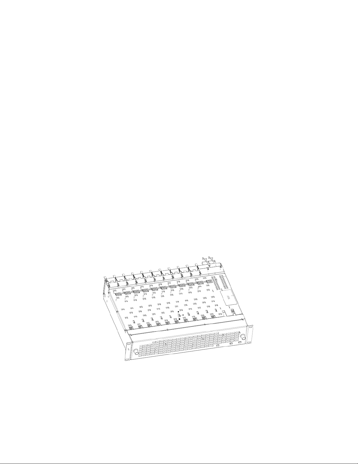
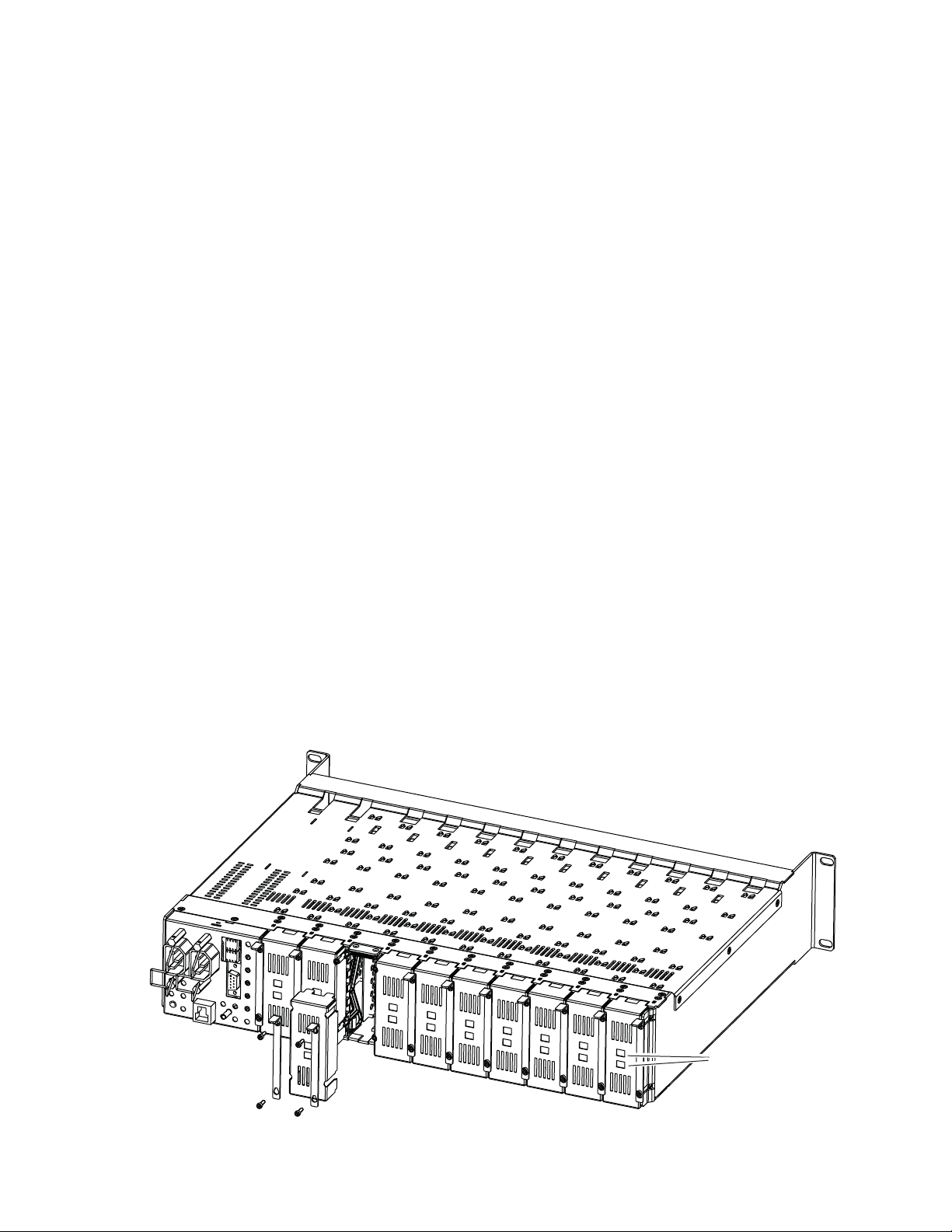
Module Placement in the GeckoFlex Frame
There are ten front and rear cell locations in the 2 RU GeckoFlex frame
Figure 1) to accommodate either audio, analog and digital video modules.
(
The 8945EDA module set may be plugged into any one of the available
GeckoFlex frame slots. It requires a single rear slot.
Figure 1. GeckoFlex Frame
10 8945EDA/-D — Instruction Manual
Page 11

Module Installation Precautions
Please read and follow the precautions listed below before installing the
front and rear modules:
• Use standard anti-static procedures during installation. As modules
can be installed or removed when the GeckoFlex frame is powered up,
before removing the cover, please use an anti-static bracelet tied to a
metal part of the frame.
• Install the rear module first, then the front module.
• When installing or removing a rear module, loosen or tighten the
screws holding the retainer clips to the frame manually with the
retainer clip tool provided inside the front cover of the frame or use a
2 mm (5/64”) hex screwdriver. Please do not use an electric screwdriver.
Note On newer 751- version GeckoFlex frames, a Rear Retainer Clip removal tool
and 2 extra retainer clips and screws for installing them are provided on the
inside of the frame cover.
Installation
• Make every effort to leave the screws holding the retainer clips in place
(do not remove them completely). They are very small and can easily
drop into other equipment causing a shorting hazard. (Two turns of the
screw should be enough to loosen the screws, 3 turns or more will
remove it.)
• When installing a rear module, tighten the screws on the retainer clips
just until snug. Do not apply more force than is necessary to seat the
rear module. Refer to the
page 33.
Mechanical specifications given in Tab le 5 on
8945EDA/-D — Instruction Manual 11
Page 12
Installation
Rear Module Installation
1. To remove a blank rear adapter cover (or a rear module already
present), manually loosen the two screws holding each retainer clip on
the rear adapter cover or rear module to the frame with the retainer clip
tool provided inside the front cover of the frame (751- model frames
only) or a 2 mm (5/64”) hex screwdriver.
Note To remove a rear module already installed, follow the same steps. It is helpful
to first remove the front module so the rear can be pulled out more easily.
1. After loosening the retainer clip screws, pull up on each retainer and
completely remove it, leaving the screws in place.
2. Remove the blank rear adapter cover by inserting the retainer clip tool
or needlenose pliers into the slots in the blank cover and pulling it off
(Figure 2).
3. Insert the rear module into the empty slot, guiding it carefully into
place.
4. Replace each retainer clip over the two screws on both sides of the
module and push down to seat the retainer clip.
5. Tighten the two screws on each retainer clip just until they come into
contract with the retainer clip then tighten about a 1/4 turn more
(maximum torque is 4-5 inch-lb/0.45-0.6Nm). Do not force or torque
the screws too tightly. The clips should not bend or be bowed.
Note All unused rear slots in a GeckoFlex frame should have a blank rear adapter
cover installed.
Figure 2. Installing Rear Module
Use retainer clip or
needlenose pliers
to pull out blank after
removing retainer clips
12 8945EDA/-D — Instruction Manual
8444_23r0
Page 13
Front Module Installation
Local Configuration
Switches S1 and S2
If you have an 8900NET module (Net Card) in your frame and will be configuring the module remotely with a web browser or the Newton Control
Panel, install it as described in
If you do not have an 8900NET (Net Card) module in the GeckoFlex frame
for remote monitoring and configuration, you will need to configure the
module using the local onboard controls before installing it in the frame as
described below.
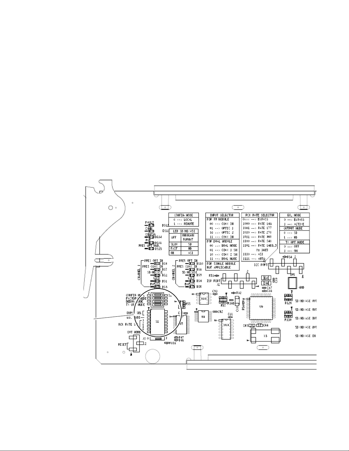
Local Configuration
Local configuration of either model 8945EDA consists of two DIP switches
(S1 and S2) highlighted in the lower left corner of
on page 14 for configuring the 8945EDA/-D with the onboard switches.
Figure 3. Configuration Switches on 8945EDA/-D Modules
Installation
Front Module Installation on page 15.
Figure 3. Refer to Tabl e 1
8945EDA/-D — Instruction Manual 13
Page 14
Installation
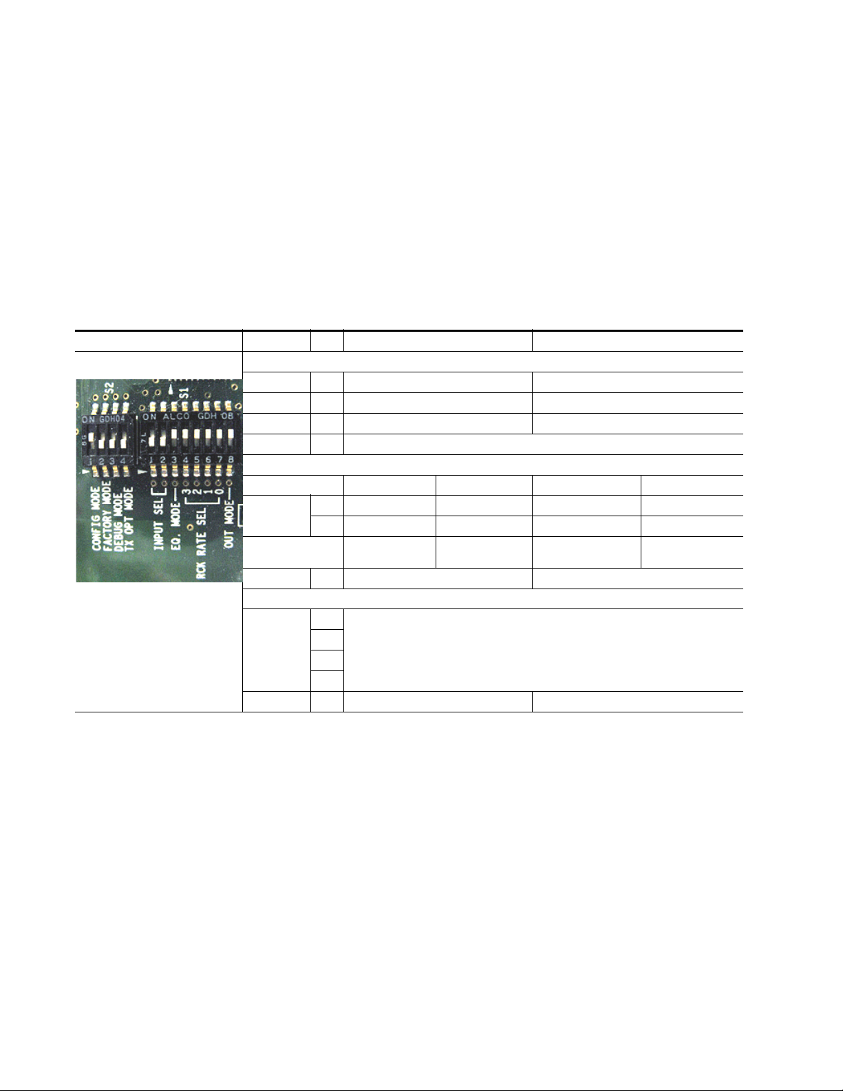
Configuration Switches S1 and S2
Ta bl e 1 gives the parameters set with the onboard switches S1 and S2 on the
8945EDA and 8945EDA-D module circuit boards. Parameters may also be
set using the web page or Newton Control panel controls when the
8900NET (Net Card) module is installed in the GeckoFlex frame. Refer to
the Configuration Summary table,
defaults and parameters for each control type.
Note Remote control settings made with the web interface will override local set-
tings. To lock out remote control, set the Config Mode to Off (LOCAL).
Table 1. Switch S1 and S2 Settings
Switches S1 and S2 Function Pin 0 (Left/Off) 1 (Right/On)
Switch S2
Config Mode
Factory Mode
Test Mode
Tx Opt Mode
Switch S1
Input Select Coax In 1 J9 Coax In 2 J10 Coax In 1 J9 (single) Coax In 2 J10 (single)
Coax Outputs J1, J3, J5, J7 J2, J4, J6, J8
Eq. Mode
Rck Rate Sel (Reclocking rate selection)
Out Mode
LOCAL (Remote control locked out) LCL&REM (Local and Remote)
1
2
3
4
1
2
3
4
5
6
7
8
01 1 0
01 0 1
Off Factory use only
Off Factory use only
Bypass Active
SD/ASI HD
Ta bl e 7 on page 41, for a complete list of
Not used on the 8945EDA/-D
J1, J2, J3, J4,
J5, J6, J7, J8
Not used on the 8945EDA/-D
J1, J2, J3, J4,
J5, J6, J7, J8
14 8945EDA/-D — Instruction Manual
Page 15

Front Module Installation
Slide top and bottom card carriers on module
over top and bottom guides on right of slot.
Module installed
Locking Pin
Front Module Side View
0642_10r0
After installing the rear module, install the front module as follows:
1. Remove the front cover of the frame if required.
2. Locate the corresponding front slot.
3. Insert the front module so that the plastic card guides on the module
top and bottom edges go over the upper and lower raised rail guides on
the right of the top and bottom of the slot (Figure 4).
4. Carefully slide the module into the rear connector.
5. Lock the front module ejector tab into the locking pin.
Figure 4. Front Module Installation
Installation
8945EDA/-D — Instruction Manual 15
Page 16

Cabling
Cabling
Inputs and Outputs
Cabling to the 8945EDA or 8945EDA-D module is done on the BNCs on the
8900WE-R rear module. Refer to
tion of the rear connections referenced below. The 8945EDA or 8945EDA-D
will accept any of the video standards listed in the Input specifications in
Ta bl e 5 on page 33.
The 8945RDA has one input and eight outputs. Refer to Ta bl e 2 and
Figure 5 on page 17 for cabling information.
The 8945RDA-D has two inputs each with four outputs. Refer to Tab le 2
and Figure 6 on page 17 for cabling information. It may also be configured
as a single DA (see Local Configuration on page 13 or Settings Web Page on
page 27).
The 8945EDA or 8945EDA-D inputs conform to the video standards listed
in the input specifications in
Figure 5 on page 17 for a detailed illustra-
Ta bl e 5 on page 33..
Table 2. Cabling Inputs and Outputs
Model Number Inputs Outputs
8945EDA J9 (J10 is not used) J1, J2, J3, J4, J5, J6, J7, J8
8945EDA-D (Dual Mode)
8945EDA-D (Single Mode) J9 or J10 set for single mode J1, J2, J3, J4, J5, J6, J7, J8
J9 (DA 1) J1, J3, J5, J7
J10 (DA 2) J2, J4, J6, J8
16 8945EDA/-D — Instruction Manual
Page 17

Figure 5. 8945EDA Rear Cabling
8900WE-R
J9: Video Input
J7: Video Output
J5: Video Output
J1: Video Output
J3: Video Output
J10: Not Used
J8: Video Output
J6: Video Output
J4: Video Output
J2: Video Output
8436_01r0
8900WE-R
J9: Video Input 1
J1: Video Output
J3: Video Output
J5: Video Output
J7: Video Output
J10: Video Input 2
J2: Video Output
J4: Video Output
J6: Video Output
J8: Video Output
8436_02r0
Cabling
Figure 6. 8945EDA-D Rear Cabling
8945EDA/-D — Instruction Manual 17
Page 18

Power Up
Power Up
Operation Indicator LEDs
The on-board LED (DS11) indicators are illustrated in Figure 7. Upon
power-up, the green PWR LED should light and the CONFIG, FAULT, and
COMM LEDs should illuminate for the duration of module initialization.
With a valid input signal connected, the green on-board PWR LED, PRES
IN LED should be on. Refer to
possible operating conditions and the resulting indicator status.
Figure 7. LEDsIndicators
Tab le 3 on page 19 to see a complete list of
The following LEDs are not used on the 8945EDA and 8945EDA-D modules:
•PRES OPT IN,
•PRES OPT MOD,
•SD/HD/ASI, and
•LOCK.
18 8945EDA/-D — Instruction Manual
Page 19

A red FAULT LED indicates an error situation and, when noted with the
other indicator LEDs, can indicate a specific problem area.
signal output and LED indications for the various input/reference combinations.
Table 3. Indicator LEDs and Conditions Indicated
LED Indication Condition
FAULT
(red)
COMM
(yellow)
CONFIG
(yellow)
PWR
(green)
PRES COAX IN
(green)
BYPASS
(yellow)
Off Normal operation
On continuously Module has detected internal fault
Off No activity on frame communication bus
Long flash Location Command received by the module from a remote control system
Short flash Activity present on the frame communication bus
Off Module is in normal operating mode
On continuously Module is initializing, changing operating modes or updating firmware
Long flash Location command received by the module from a remote control system
Off No power to module or module’s DC/DC converter failed
On continuously Normal operation, module is powered
Off Indicates no signal present on the coax input
On continuously Indicates signal present on the coax input
Off No bypass of the equalizer
On continuously Bypass of the equalizer
Power Up
Tab le 3 describes
Ta bl e 4 provides the possible input and output conditions that result from
different input signals and conditions.
Table 4. Input and Output Conditions
Input Condition Output Condition
Serial Digital Component (SDI) Serial Digital Component (SDI)
HD Digital Component (SDI) HD Digital Component (SDI)
Other carrier Other carrier
No input Passing
8945EDA/-D — Instruction Manual 19
Page 20

Remote Configuration
Remote Configuration
The 8945EDA and 8945EDA-D configuration and monitoring can also be
performed using a web browser GUI interface or a networked Newton
Control Panel when the 8900NET Network Interface module is present in
the GeckoFlex frame (8900FFN). Each of these interfaces is described below.
8900NET Module Information
Refer to the 8900NET Network Interface Module Instruction Manual available
online in PDF format for information on the 8900NET Network Interface
Module and setting up and operating the GeckoFlex 8900 frame network.
Note Upgrade software and instructions for the 8900NET can be downloaded from
the Grass Valley ftp site.
Newton Control Panel Configuration
A Newton Control Panel (hard and/or soft version) can be interfaced to the
GeckoFlex frame over the local network. Refer to the documentation that
accompanies the Newton Modular Control System for installation, config
uration, and operation information.
Control panel access offers the following considerations for module configuration and monitoring:
• Ability to separate system level tasks from operation ones, minimizing
the potential for on-air mistakes.
• Ability to group modular products—regardless of their physical locations—into logical groups (channels) that you can easily manipulate
with user-configured knobs.
• Update software for applicable modules and assign frame and panel IP
addresses with the NetConfig Networking application.
• Recommended for real-time control of module configuration parameters, providing the fastest response time.
Note Not all module functions are available with the control panel, such as factory
default recalls.
-
20 8945EDA/-D — Instruction Manual
Page 21

Remote Configuration
An example of the Newton Configurator is shown in Figure 8.
Figure 8. Newton Configurator Example
Web Browser Interface
The web browser interface provides a graphical representation of module
configuration and monitoring.
Use of the web interface offers the following considerations:
• Web access will require some normal network time delays for pro-
cessing of information.
• Configuration parameter changes may require pressing
Enter, upload processing time, and a manual screen refresh to become
effective.
• Web interface recommended for setting up module signal and slot
names, and reporting status for SNMP and monitoring.
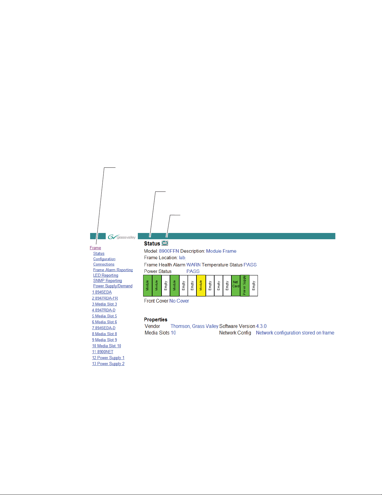
Refer to the Frame Status web page shown in Figure 9 on page 22. The 8900
modules can be addressed by clicking either on a specific module icon in
the frame status display or on a module name or slot number in the link list
on the left.
Apply button or
8945EDA/-D — Instruction Manual 21
Page 22
Remote Configuration
8436_03r0
The Links section lists the frame and its current modules. The selected link's Status
page is first displayed and the sub-list of links for the selection is opened. The sub-list
allows you to select a particular information page for the selected device.
Content display section
displays the information page
for the selected frame or module (frame slot icons are also
active links).
Refresh button for manual
update of page
Note The physical appearance of the graphics on the web pages shown in this
manual represent the use of a particular platform, browser and version of
8900NET module software. They are provided for reference only. Web pages
will differ depending on the type of platform and browser you are using and
the version of the 8900NET software installed in your system. This manual
reflects an 8900NET module with software version 4.3.0, using Internet
Explorer, the recommended web browser, and Windows XP operating
system.
For information on status and fault monitoring and reporting shown on the
module Status page, refer to
Note Click on the Refresh button to update the web page after any changes.
Figure 9. Frame Status Web Page
Status Web Page on page 24.
22 8945EDA/-D — Instruction Manual
Page 23

8945EDA and 8945EDA-D Links and Web Pages
The 8900 GUI provides the following links and web pages for the 8945EDA
modules (
• Status – reports input and output signals and frame bus communication status and module information (page 24),
• Settings – allows the configuration of the inputs and outputs (page 27),
• Slot Config – provides Locate Module and Slot Memory functions
along with links to the SNMP, LED Reporting, and Frame Alarm configuration web pages (page 29).
Figure 10. 8945EDA and 8945EDA-D Web Page Links
Figure 10):
Remote Configuration
8945EDA/-D — Instruction Manual 23
Page 24

Remote Configuration
Use
this
link
Status Web Page
The Status web pages (Figure 11 on page 25 for the 8945EDA and Figure 12
on page 26 for the 8945EDA-D) shows the signal s
and communication status with the frame bus. Color coding of the display
indicat
es the signal status.
tatus of the input signal
In general, graphics and text col
• Green = Pass – signal or reference present, no problems detected.
Red = Fault – fault condition.
•
• Yellow = Warning – signal is absent, has errors, or is mis-configured.
• Gray = Not monitored.
Under the
and the slot location of the module in the frame.
The graphic shows the input and output s
Only input signal status is reported by color in this graphic. Outputs are not
monitored (always gray). The input signal status reporting for CH1 and/or
CH 2 can be disabled on the I/O Config web page.
Also shown is the rear and front module status. Information about the
mod
ware Version, and Asset Tag number (ass
page) are given in table format at the bottom of the Status web page.
The area inside the double bars below the
sages reported from the module.
Status title are given the model description, the Frame location,
ule, such as Part Number, Serial Number, Hardware Revision, Soft-
ors used indicate the following:
ignals available for the module.
igned on the Slot Config web
graphic will report warning mes-
24 8945EDA/-D — Instruction Manual
Page 25
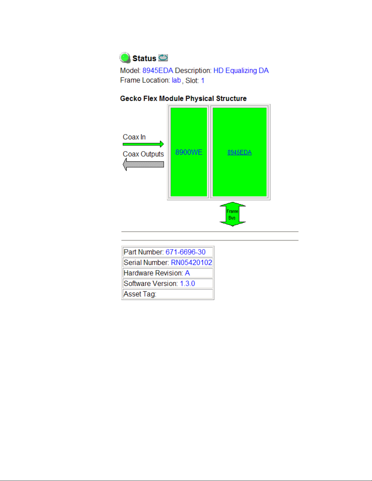
Figure 11. Status Web Page for 8945EDA Module
Remote Configuration
8945EDA/-D — Instruction Manual 25
Page 26

Remote Configuration
Figure 12. Status Web Page for 8945EDA-D Module
26 8945EDA/-D — Instruction Manual
Page 27

Settings Web Page
Use
this
link
The Settings web page for the 8945EDA (Figure 13 on page 27) and the
8945EDA-D (Figure 14 on page 28) provides configuration controls for the
module.
• Coax In 1 J9 and Coax In 2 J10 – The 8945EDA has one input at J9 that
d all eight outputs. As shown in Figure 13 on page 27, the
fee
8945EDA-D has two coax inputs that can be routed to different output
sets.
• Signal Names (8945EDA only) – names for the inputs at J9 and J10 can
be typed in for identification upstream in SNMP Trap reporting.
Note To return to the default name,clear the current characters and type enter.
• Input Reporting – Choose between Enable or Disable. The Enable parameter raises alarms towards 8900NET on the input signals (presence of
signal). The color of arrows on the Status page will be automatically
changed. The
Status web page to grey to show they are not being monitored or
reported to upper level control devices.
Remote Configuration
Disable parameter will change the color of arrows on the
• Equalizer Mode – Select
bypass the equalizer.
• Signal Format – Select the desired signal format between SD/ASI and
HD. This parameter acts on the rise and fall time value.
• Carrier Detect – Indicates the input signal detection of DA1 or DA2 (for
8945EDA-D).
Figure 13. Settings Page for 8945EDA Module
Active to enable the equalizer. Select Bypass to
8945EDA/-D — Instruction Manual 27
Page 28

Remote Configuration
Figure 14. Settings Page for 8945EDA-D Module
28 8945EDA/-D — Instruction Manual
Page 29

Slot Config Web Page
Use
this
link
Use the Slot Config web page shown in Figure 15 to perform the following
functions on the 8945EDA or 8945EDA-D module:
•Locate Module
Slot Identification
•
•Slot Memory
• Frame Health Reporting
• LED Reports
• SNMP Trap Reporting
Each of these functions is described in detail below.
Figure 15. Slot Config Web Page
Remote Configuration
8945EDA/-D — Instruction Manual 29
Page 30

Remote Configuration
Locate Module
Selecting Flash from the Locate Module pulldown flashes the yellow COMM
and CONF LEDs on the front of the module so it can be located in the
frame.
Slot Identification
You may identify the module by typing a specific name in the Name field.
The assigned name is stored on the 8900NET module and travels with the
8900NET module if it is moved to another frame. Select
factory default module name.
An asset identification may be entered in the Asset Tag field. This will appear
on the module Status web page and in the NetConfig inventory report.
Default to enter the
Slot Memory
The slot configuration for each media module is automatically polled and
refreshed periodically (about every 50 minutes) by the 8900NET module
when the
page (with 4.3.0 software) and/or the
media module Slot Config web page is selected.
Always Slot Refresh checkbox on the 8900NET Configuration web
Restore upon Install checkbox on any
When the Restore upon Install checkbox on any media module Slot Config
web page has been selected, the current configuration from that module is
saved in slot memory on the 8900NET module. This allows the current
module to be removed and when another module of the same part number,
and software version is installed, the configuration saved to the 8900NET
module will be downloaded to the installed module. The
checkbox must be selected before the current module with the saved con
figuration is removed.
Note Make sure all modules of the same model type are running the same software
version and have the same part number silk-screened on the printed circuit
board. Downloading a configuration to a module with a different software
version or part number can produce unexpected results.
If a different type of module is installed in this slot, a warning message will
state that the original module type has been replaced with another module
type. In this case, a
configuration from the previous module.
You may also select the Learn Module Config button at any time to save the
current configuration for this slot. The configuration is saved on the
8900NET module. If the 8900NET module is removed or powered down,
the stored configurations are not saved.
Clear button will appear allowing you to clear the stored
Restore upon Install
-
30 8945EDA/-D — Instruction Manual
Page 31

Remote Configuration
When no Restore upon Install checkboxes on any of the media module Slot
Config web pages are selected and the
8900NET Configuration web page is unchecked, the slot refresh polling
function on the 8900NET module will be disabled. See the
checkbox description in the 8900NET (Net Card) Network Interface Module
Instruction Manual for more details.
Note Uncheck the Restore Upon Install button before downloading new software.
Always Slot Refresh checkbox on the
Always Slot Refresh
Frame Health Reporting
This web page allows configuration of the alarms and warnings that are
reported to the external Frame Health Alarm connector on the rear of the
GeckoFlex frame. Refer to 8900NET Instruction Manual for more details.
LED Reports Link
Select the LED Reports link to open the 8900NET LED Reporting web page.
Normally, every module in the frame will report to the 8900NET module
any Fault, Signal Loss, Reference Loss, or Config Error conditions. These
conditions will be reflected by the status LEDs on the 8900NET module.
Using this web page, any of these conditions can be disabled from being
reported to the 8900NET module for each individual module and other
components (power supplies, fans) in the frame
SNMP Trap Reports Link
Select the SNMP Trap Reports link to open the 8900NET SNMP Reporting
web page. This link will only be present when SNMP Agent software has
been installed on the 8900NET module. This web page allows configura
tion of which alarms and warnings that are reported to the SNMP management software.
Refer to the 8900NET Instruction Manual for complete details on using the
8900NET web pages.
-
8945EDA/-D — Instruction Manual 31
Page 32

Software Updating
Software Updating
Software updating any of the 8945EDA modules is done using the NetConfig Networking Application PC option. The NetConfig application is
available free of charge from the Grass Valley web site.
The procedure for updating software is given in the specific 8945EDA
Release Notes when software updates become available for field updating.
Check the Grass Valley web site for update information. Refer to
Grass Valley on page 4 for more information.
All modular product documentation can be found in PDF format on the
Grass Valley web site at this link:
www.grassvalley.com/docs/modular
Contacting
32 8945EDA/-D — Instruction Manual
Page 33

Specifications
Specifications
Table 5. 8945EDA and 8945EDA-D Specifications
Parameter Value
Input
Number and type of inputs 1 or 2 BNCs (DA1: J9, DA2: J10)
Input impedance 75 ohm
Input signal type Serial digital component conforming to the following formats:
• SMPTE 292M
• SMPTE 259M (143 Mbps, 177 Mbps, 270 Mbps, 360 Mbps)
• SMPTE 344M (540 Mbps)
• 4 Mbps to 1.5 Gbps with PN20 pseudonoise sequence, maximum
ratio of 19/1
• DVB-ASI
Signal level SDI 800 mV p-p ±10% max
Return loss • >15 dB 5 to 270MHz
• >10 dB to 1.5 GHz
Equalization Auto equalizing:
Outputs
Number and type of outputs 8 BNCs
Output impedance 75 Ohm
Signal type Serial digital component conforming to the following formats:
Signal level SDI 800 mV p-p ±10%
Return loss • >15 dB 5 to 270MHz
Error Checking Transparent to embedded EDH
Signal polarity Non-inverted
Power
Input power maximum
8945EDA
8945EDA-D
Mechanical
Frame Type GeckoFlex
Number of frame slots One slot
Rear module type 8900WE-R
Rear module retainer maximum screw torque 4-5 inch-lb./0.45-0.6Nm
HD signals up to 125 m Belden 1694a
SD signals up to 330 m of Belden 1694a
• SMPTE 292M
• SMPTE 259M (143 Mbps, 177 Mbps, 270 Mbps, 360 Mbps)
• SMPTE 344M (540 Mbps)
• 4 Mbps to 1.5 Gbps with PN20 pseudonoise sequence, maximum
ratio of 19/1
• DVB-ASI
• >10 dB to 1.5 GHz
2.6 W
2.9 W
8945EDA/-D — Instruction Manual 33
Page 34

Specifications
Table 5. 8945EDA and 8945EDA-D Specifications - (continued)
Parameter Value
Environmental
Frame temperature range
Operating humidity range
Non-operating temperature
MTBF at 40°C
8945EDA
8945EDA-D
Refer to GeckoFlex Frames 8900FX/FF/FFN Signal Processing Systems
Instruction Manual at: www.grassvalley.com/docs/modular
1 512 700
1 395 000
34 8945EDA/-D — Instruction Manual
Page 35

Status Monitoring
There are a number of ways to monitor frame and module status. These
methods are summarized here. For more detailed information, refer to the
8900NET (Net Card) Network Interface Module Instruction Manual and the
8900 Gecko or 8900 GeckoFlex Frame Instruction Manuals.
All modular product documentation is available on-line in PDF format at
this link:
www.grassvalley.com/docs/modular
The main status monitoring methods include the following:
• External frame alarm output on the rear of the 8900 frame with
• LEDs on the Frame, 8900NET module, and individual frame media
• Web browser status reporting for each frame component, and
Status Monitoring
reporting from the Module Health Bus and other frame status alarm
reports,
modules,
• SNMP traps, captured by Grass Valley’s NetCentral or another SNMP
Manager Application.
Note SNMP trap information is only available when an SNMP Agent has been
installed and configured.
External Frame Alarm
An external Frame Alarm output is available on pins 8 and 9 of the RS-232
connector on the rear of the frame. The Frame Alarm outputs a voltage
level indicating there is an alarm condition on the Module Health Bus or
one of the other frame components reported to the Frame Monitor module
in a Gecko 8900TF or GeckoFlex 8900FF frame or the 8900NET module in
an 8900TFN and GeckoFlex 8900FFN frame.
• The Module Health bus is a separate line on the frame motherboard
that provides a means for older or less capable modules (such as DAs
with no microprocessor) that cannot communicate over the Frame
(serial) bus to report warning and alarm conditions to the external
Frame Alarm. All media modules in the frame report a voltage level to
this line when a warning condition occurs on the module. The specific
warning or module location is not reported, only an indication that an
warning condition has occurred.
• Frame alarm reporting from other frame components can be enabled
and disabled using DIP switches on the Frame Monitor and 8900NET
module. For frames with an 8900NET module, the Frame Alarm
Reporting web page allows configuration of the alarms and warnings
that are reported to this external Frame Health Alarm.
8945EDA/-D — Instruction Manual 35
Page 36

Status Monitoring
LED Reporting
Web Browser Interface
LEDs on the front of media modules, the Frame Monitor or 8900NET modules, and the front covers of the 8900TF/TFN and GeckoFlex FF/FFN
frames indicate status of the frame and the installed power supplies, fans
in the front covers, and module status. (The 8900TX-V/A and GeckoFlex
8900FX frames have no LED indicators on the front cover.)
• LED reporting from the modules in the frame to the 8900NET module
is configurable using the 8900NET LED Reporting web page.
• The Status LEDs for this module are described in Operation Indicator
LEDs on page 18. LEDs for the 8900NET module are described in the
8900NET (Net Card) Network Interface Instruction Manual.
The 8900NET module controls a web browser GUI that indicates frame and
module status on the following web pages:
• Frame Status web page – reports overall frame and module status in
•Module Status web page (page 24) – shows specific input and reference
• A Status LED icon on each web page reflects the module status on the
SNMP Reporting
The GeckoFlex 8900 Series system uses the Simple Network Monitoring
Protocol (SNMP) internet standard for reporting status information to
remote monitoring stations. When SNMP Agent software is installed on the
8900NET module, enabled status reports are sent to an SNMP Manager
such as the Grass Valley’s NetCentral application.
Status reporting for the frame is enabled or disabled with the configuration
DIP switches on the 8900NET module. Most module status reporting items
can be enabled or disabled on individual configuration web pages.
colored graphical and text formats. Refer to Figure 9 on page 22 for an
example.
signal configuration error status to the module along with module
status and information (part number, serial number, hardware version,
software/firmware/boot versions, and Asset number (as assigned on
the Slot Config web page).
module Status web page where warnings and faults are displayed and
is a link to the module Status web page.
36 8945EDA/-D — Instruction Manual
Page 37

Service
Power-up Diagnostics Failure
Troubleshooting
The 8945EDA modules make extensive use of surface-mount technology
and programmed parts to achieve compact size and adherence to
demanding technical specifications. Circuit modules should not be ser
viced in the field unless otherwise directed by Customer Service.
If the module has not passed self-diagnostics, do not attempt to troubleshoot. Return the unit to Grass Valley (see Module Repair on page 37).
Electronic Circuit Breaker
Service
-
The electronic circuit breaker works during a fault condition or an overcurrent which stops the module.
Remove the module and replace it in the frame. If the problem persists,
please refer to the Grass Valley Customer Service.
Module Repair
If the module is still not operating correctly, replace it with a known good
spare and return the faulty module to a designated Grass Valley repair
depot. Call your Grass Valley representative for depot location.
Refer to Contacting Grass Valley on page 4 at the front of this document for
the Grass Valley Customer Service Information number.
8945EDA/-D — Instruction Manual 37
Page 38

Service
Alarms Table
The table below describes the different type of alarms:
Tab l e 6 . L i st o f A la r ms
Alarm
degree
High Hardware failure: no application code Fault red on Boot status page: Only this page is visible, software is
High Bad rear module: if optical rear type on
EDA and EDA-D
High Electrical signal detect on DA 1 (DUAL
or single mode2) only when electric
selected
High Electrical signal detect on DA 2(DUAL
or single mode1) only when electric
selected
Equalizer 1 bypassed Bypass SETTING page:
Equalizer 2 bypassed Bypass SETTING page:
INPUT 1 REPORTED:
previous described alarms reported
Description LED Indicator WEB page comments
downloading
Fault: flashing Status page: bad rear module
PID_RES_DEVICE_STATUS: rear module in yellow
color (green if OK)
PRES COAX IN 1 STATUS PAGE:
elec input arrow is green/red/yellow
SETTING page:
carrier detect : present / not present
PRES COAX IN 2 STATUS PAGE:
elec input arrow are green/red/yellow
SETTING page:
carrier detect: present / not present
equalizer mode: BYPASS
equalizer mode: BYPASS
No impact on LED status Status page:
corresponding input arrow color green or yellow
Query status
towards
Netcard&SNMP
YES
YES
YES
No
No
YES
INPUT 1 NOT REPORTED:
previous described alarms are not
reported
INPUT 2 REPORTED:
previous described alarms reported
INPUT 2 NOT REPORTED:
previous described alarms are not
reported
Setting page:
input reporting: enable/disable
No impact on LED status Status page:
corresponding input arrow color green or yellow
Setting page:
input reporting: enable/disable
No impact on LED status Status page:
corresponding input arrow color green or yellow
Setting page:
input reporting: enable/disable
No impact on LED status Status page:
corresponding input arrow color green or yellow
Setting page:
input reporting: enable/disable
NO
YES
NO
38 8945EDA/-D — Instruction Manual
Page 39

Functional Description
HD/SD
SDI In
Equalizer
8X
HD/SD
SDI
Out
Equalizer bypass
A block diagram of the 8945EDA is shown in Figure 16 and the 8945EDA-D
in Figure 17.
Figure 16. 8945EDA Block Diagram
Figure 17. 8945EDA-D Block Diagram
Functional Description
HD/SD
SDI In
HD/SD
SDI In
Equalizer bypass
Equalizer
Equalizer bypass
Equalizer
4X HD/
SD-SDI
Out
4X HD/
SD-SDI
Out
8945EDA/-D — Instruction Manual 39
Page 40

Functional Description
40 8945EDA/-D — Instruction Manual
Page 41

Configuration Summary Table
Ta bl e 7 provides a complete summary of the module functions and a com-
parison of the functionality available with each control type along with the
ranges and default values for each parameter on each control.
Table 7. Summary of Configuration Functions
Function
Typ e
Config Mode LCL&REM LCL or LCL&REM N/A
Assign Input Coax In 1 J9
to BNC outputs
Assign Input Coax In 2
J10 to BNC outputs
(8945EDA-D only)
Coax In 1 J9 Signal name
for SNMP reporting
(8945EDA-D only)
Coax In 2 J10 Signal
name for SNMP reporting
Input reporting for DA1 Enable Enable or Disable
(8945EDA-D only)
Input reporting for DA2
Equalizer mode for DA1 Active Active or Bypass
(8945EDA-D only)
Equalizer mode for DA2
Signal format for DA1 SD/ASI SD/ASI or HD
(8945EDA-D only)
Signal format for DA2
Default
Dual Mode = DA1
(Outputs
J1, J3, J5, J7)
Dual Mode = DA2
(Outputs
J2, J4, J6, J8)
Coax In 1 J9 12 character limit
Coax In 2 J10 12 character limit
Enable Enable or Disable
Active Active or Bypass
SD/ASI SD/ASI or HD
Range/Choices
Resolution
Dual Mode: DA1
(Outputs J1, J3, J5, J7)
Single Mode:
DA1 and DA2
(Outputs J1, J2, J3, J4,
J5, J6, J7, J8)
Dual Mode: DA2
(Outputs J2, J4, J6, J8)
Single Mode:
DA1 and DA2
(Outputs J1, J2, J3, J4,
J5, J6, J7, J8)
Web Page/
Function Name
Settings
Routing Mode DA1
Coax In 2 J9
Dual: select DA1
Single: select DA1 and DA2
Settings
Routing Mode DA2
Coax In 2 J10
Dual: select DA2
Single: select DA1 and DA2
Settings
Coax In 1 J9 Signal Name
Enter signal name
Settings
Coax In 2 J10 Signal Name
Enter signal name
Settings
Input Reporting
Set for DA1
Settings
Input Reporting
Set for DA2
Settings
Equalizer Mode
Set for DA1
Settings
Equalizer Mode
Set for DA2
Settings
Signal Format for DA1
SD/ASI or HD button
Settings
Signal Format for DA2
SD/ASI or HD button
Local Onboard
Control
Function Switch S2
Pin 1:
0 (left): LOCAL
1 (right): LCL&REM
Function Switch S1
Dual DA1
Pin 1: 0 (left)
Pin 2: 0 (left)
Single DA1 and DA2
Pin 1: 1 (right)
Pin 2: 0 (left)
Function Switch S1
Dual DA2
Pin 1: 1(left)
Pin 2: 1 (left)
Single DA1 and DA2
Pin 1: 0 (left)
Pin 2: 1 (right)
N/A N/A
N/A N/A
N/A Input Report 1
N/A Input Report 2
Function Switch S1
Pin 3:
0 (left): Bypass
1 (right): Active
Function Switch S1
Pin 3:
0 (left): Bypass
1 (right): Active
Function Switch S1
Output Mode DA1/DA2
Pin 8:
0 (left): SD/ASI
1 (right): HD
Both DAs are the same
Newton
Control
Panel
N/A
Rout Mod 1
Rout Mod 2
Equal 1
Equal 2
SgnFormat 1
SgnFormat 2
8945EDA/-D — Instruction Manual 41
Page 42

Configuration Summary Table
42 8945EDA/-D — Instruction Manual
Page 43

Index
Numerics
8900NET (Net Card) module 20, 22
A
Auto cable equalization 9
B
block diagrams 39
BYPASS LED 19
C
cabling 16
Carrier Detect 27
Clear button 30
Coax 1 and 2 27
Colors on graphics 24
COMM 19
CONF (configuring) LED 19
CONFIG 19
configuration
summary table
with remote controls 20
control panel 20
41
D
FAQ database 4
FAULT LED 19
fault table 19
Frame Health Reporting 31
Frame Status web page 22, 36
frequently asked questions 4
front module
installation
15
G
GeckoFlex frame
frame alarm
module placement 10
graphical user interface (GUI) 23
Grass Valley web site 4
35
I
Input power maximum 33
Input Reporting 27
inputs
specifications
installation 10
front module 15
precautions 11
rear module 12
Internet Explorer
recommended web browser
33
22
documentation online 4
L
E
environmental 34
Equalizer Mode 27
F
factory defaults
summary table
8945EDA/-D — Instruction Manual 43
41
LED Reporting web page 31
LEDs 18
local configuration (No 8900NET Card) 13
Locate Module function 30
M
Module Health Bus 35
module installation precautions 11
Page 44

Index
Module Status web page 36
MTBF 34
N
NetConfig PC application
required for updating software
Newton Control Panel
overview
summary table 41
20
O
online documentation 4
operating system 22
outputs
specifications
33
P
PWR LED 18, 19
R
rear module
installation
installation precautions 11
rear module retainer clip
torque specification
Refresh button 22
Remote control 9
Restore upon Install checkbox 30
retainer clip tool 12
12
33
32
signal name 41
web page for enabling 31
software download from web 4
software updating 32
specifications 10, 33
status monitoring 35
Status web page 24
Switches S1 and S2
for local configuration
14
T
table of alarms 38
W
web browser
overview
recommended 22
web site
documentation
FAQ database 4
Grass Valley 4
software download 4
21
4
S
service 37
Settings web page 27
SIG_PRES LED 18
Signal Format 27
signal names
for SNMP reporting
Slot Config web page 29
slot memory 30
SNMP reporting
overview
44 8945EDA/-D — Instruction Manual
36
27
 Loading...