

Page 1
8943RDA/-D/-DFR
SD/HD/3G-SDI FIBER READY RECLOCKING DA
Instruction Manual
Software Version 1.1.2
071859204
MAY 2010
Page 2

Affiliate with the N.V. KEMA in The Netherlands
CERTIFICATE
Certificate Number: 510040.001
The Quality System of:
Thomson Inc, and it’s wordwide Grass Valley division affiliates DBA
GRASS VALLEY
Headquarters
400 Providence Mine Rd
Nevada City, CA 95959
United States
15655 SW Greystone Ct.
Beaverton, OR 97006
United States
10 Presidential Way
Suite 300
Woburn, MA 01801
United States
Kapittelweg 10
4827 HG Breda
The Nederlands
7140 Baymeadows Way
Ste 101
Jacksonville, FL 32256
United States
2300 So. Decker Lake Blvd.
Salt Lake City, UT 84119
United States
Rue du Clos Courtel
CS 31719
35517 Cesson-Sevigné Cedex
France
1 rue de l’Hautil
Z.I. des Boutries BP 150
78702 Conflans-Sainte
Honorine Cedex
France
Technopole Brest-Iroise
Site de la Pointe du Diable
CS 73808
29238 Brest Cedex 3
France
40 Rue de Bray
2 Rue des Landelles
35510 Cesson Sevigné
France
Spinnereistrasse 5
CH-5300 Turgi
Switzerland
Brunnenweg 9
D-64331 Weiterstadt
Germany
Carl-Benz-Strasse 6-8
67105 Schifferstadt
Germany
Including its implementation, meets the requirements of the standard:
ISO 9001:2008
Scope:
The design, manufacture and support of video and audio hardware and software products and
related systems
.
This Certificate is valid until: June 14, 2012
This Certificate is valid as of: June 14, 2009
Certified for the first time: June 14, 2000
H. Pierre Sallé
President
KEMA-Registered Quality
The method of operation for quality certification is defined in the KEMA General Terms
And Conditions For Quality And Environmental Management Systems Certifications.
Integral publication of this certificate is allowed.
KEMA-Registered Quality, Inc.
4377 County Line Road
Chalfont, PA 18914
Ph: (215)997-4519
Fax: (215)997-3809
CRT 001 073004
ccredited By:
ANAB
A
Page 3

8943RDA/-D/-DFR
SD/HD/3G-SDI FIBER READY RECLOCKING DA
Instruction Manual
Software Version 1.1.2
071859204
MAY 2010
Page 4
Contacting Grass Valley
International
Support Centers
Local Support
Centers
(available
during normal
business hours)
France
24 x 7
Australia and New Zealand: +61 1300 721 495 Central/South America: +55 11 5509 3443
Middle East: +971 4 299 64 40 Near East and Africa: +800 8080 2020 or +33 1 48 25 20 20
Europe
+800 8080 2020 or +33 1 48 25 20 20
Hong Kong, Taiwan, Korea, Macau: +852 2531 3058 Indian Subcontinent: +91 22 24933476
Asia
Southeast Asia/Malaysia: +603 7805 3884 Southeast Asia/Singapore: +65 6379 1313
China: +861 0660 159 450 Japan: +81 3 5484 6868
Belarus, Russia, Tadzikistan, Ukraine, Uzbekistan: +7 095 2580924 225 Switzerland: +41 1 487 80 02
S. Europe/Italy-Roma: +39 06 87 20 35 28 -Milan: +39 02 48 41 46 58 S. Europe/Spain: +34 91 512 03 50
Benelux/Belgium: +32 (0) 2 334 90 30 Benelux/Netherlands: +31 (0) 35 62 38 42 1 N. Europe: +45 45 96 88 70
Germany, Austria, Eastern Europe: +49 6150 104 444 UK, Ireland, Israel: +44 118 923 0499
Copyright © Thomson, Inc. All rights reserved.
This product may be covered by one or more U.S. and foreign patents.
United States/Canada
24 x 7
+1 800 547 8949 or +1 530 478 4148
Grass Valley Web Site
The www.grassvalley.com web site offers the following:
Online User Documentation — Current versions of product catalogs, brochures,
data sheets, ordering guides, planning guides, manuals, and release notes
in .pdf format can be downloaded.
FAQ Database — Solutions to problems and troubleshooting efforts can be
found by searching our Frequently Asked Questions (FAQ) database.
Software Downloads — Download software updates, drivers, and patches.
4 8943RDA/-D/-DFR — Instruction Manual
Page 5

Contents
Preface. . . . . . . . . . . . . . . . . . . . . . . . . . . . . . . . . . . . . . . . . . . . . . . . . . . . . . . . . . . . . . . . . . . . . 7
8943RDA/-D/-DFR
SD/HD/3G-SDI Reclocking DA Modules
About This Manual . . . . . . . . . . . . . . . . . . . . . . . . . . . . . . . . . . . . . . . . . . . . . . . . . . . . . 7
. . . . . . . . . . . . . . . . . . . . . . . . . . . . . . . . . 9
Introduction . . . . . . . . . . . . . . . . . . . . . . . . . . . . . . . . . . . . . . . . . . . . . . . . . . . . . . . . . . . 9
Features. . . . . . . . . . . . . . . . . . . . . . . . . . . . . . . . . . . . . . . . . . . . . . . . . . . . . . . . . . . . . . 10
Installation . . . . . . . . . . . . . . . . . . . . . . . . . . . . . . . . . . . . . . . . . . . . . . . . . . . . . . . . . . . 11
Module Placement in the GeckoFlex Frame . . . . . . . . . . . . . . . . . . . . . . . . . . . . . 11
Module Installation Precautions . . . . . . . . . . . . . . . . . . . . . . . . . . . . . . . . . . . . . 12
Rear Module Installation . . . . . . . . . . . . . . . . . . . . . . . . . . . . . . . . . . . . . . . . . . . 13
Fiber Optics Submodule Installation (8943RDA-DFR only) . . . . . . . . . . . . . . 14
Front Module Installation. . . . . . . . . . . . . . . . . . . . . . . . . . . . . . . . . . . . . . . . . . . 19
Cabling . . . . . . . . . . . . . . . . . . . . . . . . . . . . . . . . . . . . . . . . . . . . . . . . . . . . . . . . . . . . . . 21
Fiber Optic Cleaning Requirement . . . . . . . . . . . . . . . . . . . . . . . . . . . . . . . . . . . . . 21
Video Input(s) . . . . . . . . . . . . . . . . . . . . . . . . . . . . . . . . . . . . . . . . . . . . . . . . . . . . . . 21
Video Outputs . . . . . . . . . . . . . . . . . . . . . . . . . . . . . . . . . . . . . . . . . . . . . . . . . . . . . . 22
8943RDA Module Cabling . . . . . . . . . . . . . . . . . . . . . . . . . . . . . . . . . . . . . . . . . . . . 22
8943RDA-D Module Cabling. . . . . . . . . . . . . . . . . . . . . . . . . . . . . . . . . . . . . . . . . . 23
8943RDA-DFR Module Cabling . . . . . . . . . . . . . . . . . . . . . . . . . . . . . . . . . . . . . . . 24
Power Up . . . . . . . . . . . . . . . . . . . . . . . . . . . . . . . . . . . . . . . . . . . . . . . . . . . . . . . . . . . . 25
Operation Indicator LEDs . . . . . . . . . . . . . . . . . . . . . . . . . . . . . . . . . . . . . . . . . . . . 25
Collective Module Status Reporting . . . . . . . . . . . . . . . . . . . . . . . . . . . . . . . . . . 27
Configuration. . . . . . . . . . . . . . . . . . . . . . . . . . . . . . . . . . . . . . . . . . . . . . . . . . . . . . . . . 28
Configuration Summary. . . . . . . . . . . . . . . . . . . . . . . . . . . . . . . . . . . . . . . . . . . . . . 28
Input Operating Modes. . . . . . . . . . . . . . . . . . . . . . . . . . . . . . . . . . . . . . . . . . . . . 28
Input to Output Mapping. . . . . . . . . . . . . . . . . . . . . . . . . . . . . . . . . . . . . . . . . . . 32
Local Onboard Configuration . . . . . . . . . . . . . . . . . . . . . . . . . . . . . . . . . . . . . . . . . 33
Set INPUT OP MODE . . . . . . . . . . . . . . . . . . . . . . . . . . . . . . . . . . . . . . . . . . . . . . 35
Set OUTPUT SOURCE . . . . . . . . . . . . . . . . . . . . . . . . . . . . . . . . . . . . . . . . . . . . . 36
Remote Configuration . . . . . . . . . . . . . . . . . . . . . . . . . . . . . . . . . . . . . . . . . . . . . . . 38
8900NET Module Information . . . . . . . . . . . . . . . . . . . . . . . . . . . . . . . . . . . . . . . 38
Newton Control Panel Configuration. . . . . . . . . . . . . . . . . . . . . . . . . . . . . . . . . 38
Web Browser Interface . . . . . . . . . . . . . . . . . . . . . . . . . . . . . . . . . . . . . . . . . . . . . 39
8943RDA Module Links and Web Pages . . . . . . . . . . . . . . . . . . . . . . . . . . . . . . 41
8943RDA Module Configuration and Operation . . . . . . . . . . . . . . . . . . . . . . . . . 42
Configuration. . . . . . . . . . . . . . . . . . . . . . . . . . . . . . . . . . . . . . . . . . . . . . . . . . . . . . . 43
Local Configuration. . . . . . . . . . . . . . . . . . . . . . . . . . . . . . . . . . . . . . . . . . . . . . . . 43
Remote Configuration. . . . . . . . . . . . . . . . . . . . . . . . . . . . . . . . . . . . . . . . . . . . . . 43
8943RDA-D Module Configuration and Operation. . . . . . . . . . . . . . . . . . . . . . . 52
Configuration. . . . . . . . . . . . . . . . . . . . . . . . . . . . . . . . . . . . . . . . . . . . . . . . . . . . . . . 53
Local Configuration. . . . . . . . . . . . . . . . . . . . . . . . . . . . . . . . . . . . . . . . . . . . . . . . 53
Remote Configuration. . . . . . . . . . . . . . . . . . . . . . . . . . . . . . . . . . . . . . . . . . . . . . 53
8943RDA-DFR Module Configuration and Operation . . . . . . . . . . . . . . . . . . . . 61
8943RDA/-D/-DFR — Instruction Manual 5
Page 6

Contents
Configuration . . . . . . . . . . . . . . . . . . . . . . . . . . . . . . . . . . . . . . . . . . . . . . . . . . . . . . 62
Local Configuration . . . . . . . . . . . . . . . . . . . . . . . . . . . . . . . . . . . . . . . . . . . . . . . 62
Remote Configuration . . . . . . . . . . . . . . . . . . . . . . . . . . . . . . . . . . . . . . . . . . . . . 62
Software Updating . . . . . . . . . . . . . . . . . . . . . . . . . . . . . . . . . . . . . . . . . . . . . . . . . . . . 79
Status Monitoring. . . . . . . . . . . . . . . . . . . . . . . . . . . . . . . . . . . . . . . . . . . . . . . . . . . . . 80
External Frame Alarm . . . . . . . . . . . . . . . . . . . . . . . . . . . . . . . . . . . . . . . . . . . . . . . 80
LED Reporting. . . . . . . . . . . . . . . . . . . . . . . . . . . . . . . . . . . . . . . . . . . . . . . . . . . . . . 81
Web Browser Interface. . . . . . . . . . . . . . . . . . . . . . . . . . . . . . . . . . . . . . . . . . . . . . . 81
SNMP Reporting. . . . . . . . . . . . . . . . . . . . . . . . . . . . . . . . . . . . . . . . . . . . . . . . . . . . 81
Specifications. . . . . . . . . . . . . . . . . . . . . . . . . . . . . . . . . . . . . . . . . . . . . . . . . . . . . . . . . 82
Service . . . . . . . . . . . . . . . . . . . . . . . . . . . . . . . . . . . . . . . . . . . . . . . . . . . . . . . . . . . . . . 85
Power-up Diagnostics Failure. . . . . . . . . . . . . . . . . . . . . . . . . . . . . . . . . . . . . . . . . 85
Troubleshooting . . . . . . . . . . . . . . . . . . . . . . . . . . . . . . . . . . . . . . . . . . . . . . . . . . . . 85
Electronic Circuit Breaker . . . . . . . . . . . . . . . . . . . . . . . . . . . . . . . . . . . . . . . . . . 85
Module Repair. . . . . . . . . . . . . . . . . . . . . . . . . . . . . . . . . . . . . . . . . . . . . . . . . . . . . . 85
Block Diagrams. . . . . . . . . . . . . . . . . . . . . . . . . . . . . . . . . . . . . . . . . . . . . . . . . . . . . . . 86
Configuration Summary Table. . . . . . . . . . . . . . . . . . . . . . . . . . . . . . . . . . . . . . . . . . 89
Index. . . . . . . . . . . . . . . . . . . . . . . . . . . . . . . . . . . . . . . . . . . . . . . . . . . . . . . . . . . . . . . . . . . . . . 93
6 8943RDA/-D/-DFR — Instruction Manual
Page 7

Preface
About This Manual
This manual describes the features of a specific 8900 module in the
GeckoFlex Signal Processing System families. As part of this module
family, it is subject to Safety and Regulatory Compliance described in the
GeckoFlex 8900 Series frame documentation (see the GeckoFlex Frames
8900FX/FF/FFN Signal Processing System Instruction Manual).
All Modular product manuals can be found on-line in PDF format at this
link:
www.grassvalley.com/docs/modular
8943RDA/-D/-DFR — Instruction Manual 7
Page 8

Preface
8 8943RDA/-D/-DFR — Instruction Manual
Page 9

8943RDA/-D/-DFR SD/HD/3G-SDI Reclocking DA Modules
Introduction
This manual covers installation, configuration, and operation of the
8943RDA, 8943RDA-D, and 8943RDA-DFR (Fiber Ready) SD/HD/3G-SDI
reclocking DAs supporting data rates up to 3Gb. All outputs are
non-inverting and will support DVB ASI outputs.
These modules install in a GeckoFlex frame with a front and rear module
for each model. All models require only one slot in the GeckoFlex frame.
The 8943RDA is an SD/HD/3G-SDI reclocking distribution amplifier providing one electrical input that can be output on eight reclocked outputs. It
can distribute SD/HD/3G-SDI video as well as DVB ASI formats, making
it ideal for mixed format installations or installations where an upgrade to
HD is planned. It requires the 89003E-R rear module.
The 8943RDA-D is a dual reclocking distribution amplifier with two electrical inputs that can be assigned in configuration to any of four reclocked
output pairs. It can be used to distribute SD/HD/3G-SDI video and DVB
ASI format signals, making it ideal for mixed format applications or instal
lations where an upgrade to HD is planned. It requires the 89003E-R rear
module.
The 8943RDA-DFR is a fiber-ready reclocking distribution amplifier providing two electrical inputs and three reclocked electrical output pairs plus
one single reclocked BNC. In addition, the module supports up to two fiber
optic inputs, two fiber optic outputs, or one fiber optic input and one
output when one of several different optional fiber optic submodules is
installed. Electrical and fiber optic inputs can all be active and outputs can
be mapped in any combination in configuration. This makes this model
ideal for receiving DVB ASI signals from distant downlinks or transmitting
them to remote uplinks. It requires the 89003FR-R rear module.
-
8943RDA/-D/-DFR — Instruction Manual 9
Page 10

Features
Features
The features of the 8943RDA modules include:
• Multi-format SD-SDI, HD-SDI, 3G-SDI on electrical inputs and outputs,
• Non-inverted outputs allow distribution of signals such as DVB ASI,
• Reclocked SD, HD, or 3G electrical outputs which reduce jitter on the
incoming signal,
• Auto cable auto equalization for up to 400 meters of cable in the case of
SD-SDI and DVB ASI and up to 140 meters of cable in the case of
HD-SDI (1.485 Gb/s), 90 meters (Input 1) and 100 meters (Input 2) for
3G-SDI (3 Gb/s) signals,
• Accepts a wide range of standard definition or high definition input
signals,
• 8943RDA-D and 8943RDA-DFR inputs can be mapped to output pairs
in any combination,
• Provides a bypass mode for signal rates not supported by the reclocker,
• Provide alarm (signal presence detection) and status management,
• Supports SNMP MIB reporting basic board alarms, and
• Remote control and monitoring support: web pages, Newton control
panel, and NetConfig management system.
In addition to the features above, the 8943RDA-DFR fiber ready model with
the 89003FR-R rear module can be populated with any one SFP (Small
Form-factor Pluggable) dual transmitter (two outputs), transceiver (one
input/one output), or dual receiver (two inputs) submodules for fiber optic
interface as listed in
Ta bl e 1 on page 14.
10 8943RDA/-D/-DFR — Instruction Manual
Page 11
Installation
Module Placement in the GeckoFlex Frame
Installation
The front and the rear modules for each model are delivered together as a
set as follows:
• 8943RDA front module with the 89003E-R rear module
• 8943RDA-D front module with the 89003E-R rear module
• 8943RDA-DFR front fiber ready module that accepts one optional SFP
fiber optic submodule (see Tabl e 1 on pa ge 14 for model numbers) with
the 89003FR-R rear module
The front and rear modules can be plugged in and removed from a
GeckoFlex frame with power on, without disrupting operation on adjacent
modules. When power is applied to the module, LED indicators reflect the
initialization process (see
Power Up on page 25).
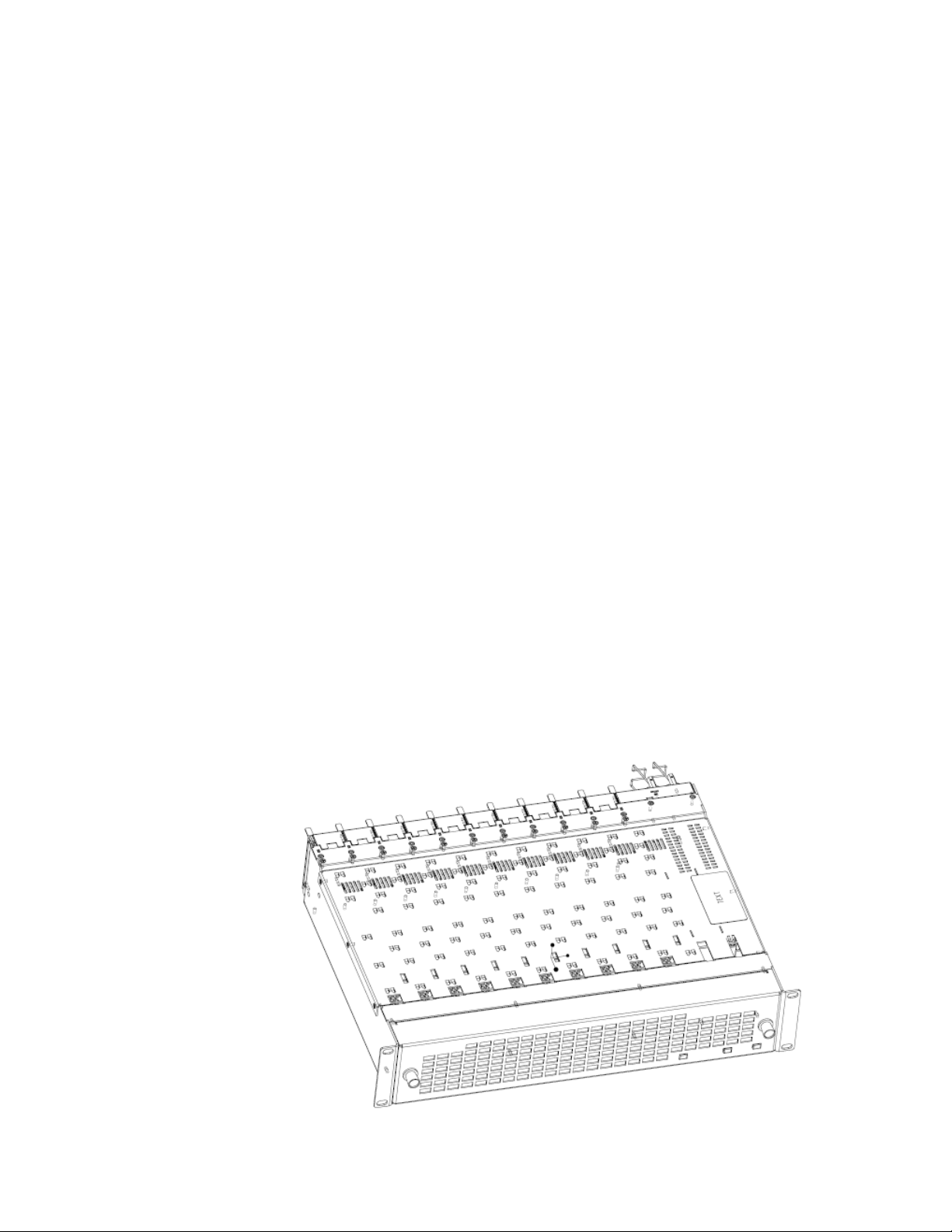
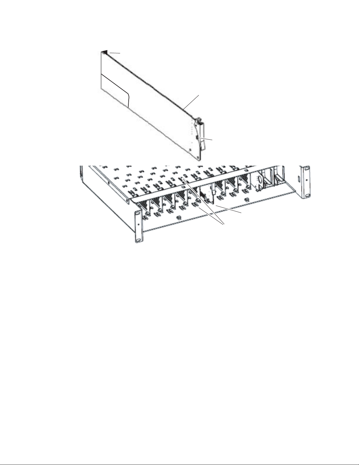
There are ten rear and front slot locations in the 2 RU frame to accommodate either video or audio modules of all types (Figure 1). Some GeckoFlex
modules use two slots. The 89003E-R used with the 8943RDA and
8943RDA-D and the 89003FR-R rear modules used with the 8943RDA-DFR
should be installed in any available single slot location on the back of the
frame first. Then the 8943RDA/-D/-DFR front module should be plugged
into the corresponding front slot.
Note All unused rear slots in a GeckoFlex frame should have a blank rear adapter
cover installed.
Figure 1. GeckoFlex Frame
8943RDA/-D/-DFR — Instruction Manual 11
Page 12

Installation
Module Installation Precautions
Please read and follow the precautions listed below before installing the
front and rear modules and any fiber optic option submodules
(8943RDA-DFR models only):
• Use standard anti-static procedures during installation. As modules
can be installed or removed when the GeckoFlex frame is powered up,
before removing the cover, please use an anti-static bracelet tied to a
metal part of the frame.
• Install the rear module first, then the optical submodule option on the
8943RDA-DFR front module (used only on the 8943RDA-DFR), then
the front module.
• When installing or removing a rear module, loosen or tighten the
screws holding the retainer clips to the frame manually with the
retainer clip tool provided inside the front cover of the frame or use a
2 mm (5/64”) hex screwdriver. Please do not use an electric screwdriver.
Note On newer 751- version GeckoFlex frames, a Rear Retainer Clip removal tool
and 2 extra retainer clips and screws for installing them are provided on the
inside of the frame cover.
• Make every effort to leave the screws holding the retainer clips in place
(do not remove them completely). They are very small and can easily
drop into other equipment causing a shorting hazard. (Two turns of the
screw should be enough to loosen the screws, 3 turns or more will
remove it.)
• When installing a rear module, tighten the screws on the retainer clips
just until snug. Do not apply more force than is necessary to seat the
rear module. Refer to the
page 82.
• If using a fiber optic submodule on the 8943RDA-DFR fiber ready
module, handle it carefully, use anti-static precautions, and read the
Fiber Optic Cleaning Requirement on page 21 before cabling.
Mechanical specifications given in Tab le 10 o n
12 8943RDA/-D/-DFR — Instruction Manual
Page 13
Rear Module Installation
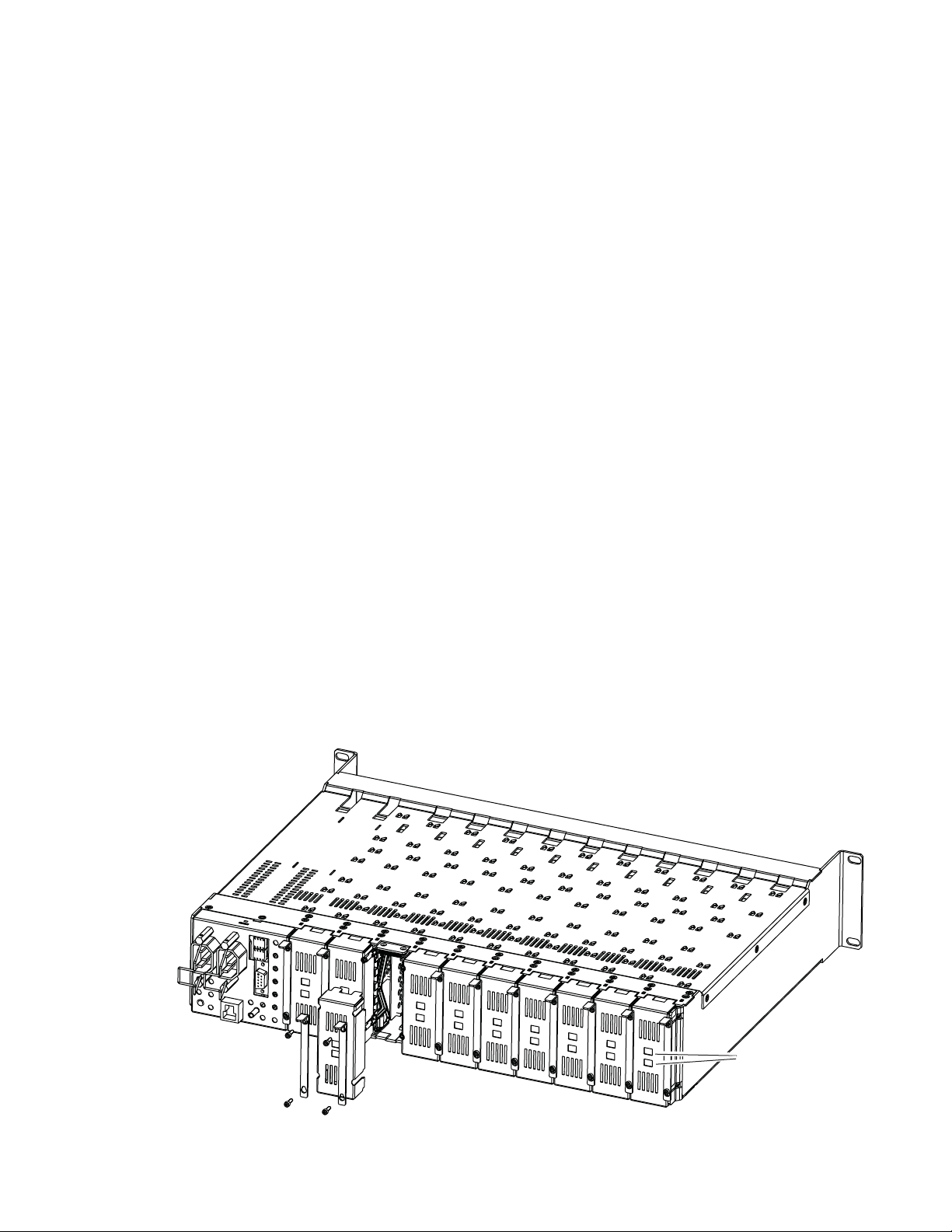
To install the rear module, refer to Figure 2 and the instructions below:
1. To remove a blank rear adapter cover (or a rear module already
present), manually loosen the two screws holding each retainer clip on
the rear adapter cover or rear module to the frame with the retainer clip
tool provided inside the front cover of the frame (newer model frames
only) or a 2 mm (5/64”) hex screwdriver. Do not remove the screws.
Note To remove a rear module already installed, follow the same steps. It is helpful
to first remove the front module so the rear can be pulled out more easily.
2. After loosening the retainer clip screws, pull up on each retainer and
completely remove it, leaving the screws in place.
3. Remove the blank rear adapter cover by inserting needlenose pliers
into the slots in the blank cover and pulling it off.
4. Insert the rear module into the empty slot, guiding it carefully.
5. Replace each retainer clip over the two screws on both sides of the
module and push down to seat the retainer clip.
Installation
6. Tighten the two screws on each retainer clip just until they come into
contract with the retainer clip then tighten about a 1/4 turn more
(maximum torque is 4-5 inch-lb/0.45-0.6Nm). Do not force or torque
the screws too tightly. The clips should not bend or be bowed.
Note All unused rear slots in a GeckoFlex frame should have a blank rear adapter
cover installed.
Figure 2. Installing Rear Module (751- Version Frame)
8444_23r0
Use retainer clip or
needlenose pliers
to pull out blank after
removing retainer clips
8943RDA/-D/-DFR — Instruction Manual 13
Page 14

Installation
Fiber Optics Submodule Installation (8943RDA-DFR only)
The 8943RDA-DFR front modules can be populated with any one of the
SFP dual transmitter, transceiver, or dual receiver submodules listed in
Ta bl e 1.
Table 1. SFP Fiber Optic Submodule Option Models
SFP Model Number Transmitter Frequencies Supported
SFP-13103G-M1DTX-K 1310 nm
Receiver Frequencies Supported
SFP-13103G-M1DRX-K 1270 nm >1610 nm
Transceiver Frequencies Supported
SFP-13103G-M1TRX-K 1310 nm (input) and 1310 nm (output)
The optional strap mount SFP Fiber Optic kit for GeckoFlex fiber-ready
modules (handling video from 143 Mb/s to 3
• One Strap Mount SFP Fiber Optic Submodule (labeled for type)
• Mounting bracket for submodule installation
Gb/s) includes:
• Jumper cable assembly for connecting submodule to front module rear
connector
Installation of the submodule involves three steps:
1. Mount the metal bracket to the submodule,
2. Mount the submodule and bracket on the front of the 8943RDA-DFR
front module before it is installed in the frame, and
3. Install the jumper cable assembly to the submodule and the front
module rear connectors.
CAUTION The Fiber Optic submodule is static sensitive. Use static handling precautions
when installing or removing the submodule.
14 8943RDA/-D/-DFR — Instruction Manual
Page 15
Installation
V-connection
SCA-2 (electrical) connector
Jumper cable connectors
SCA-2 (electrical) connector
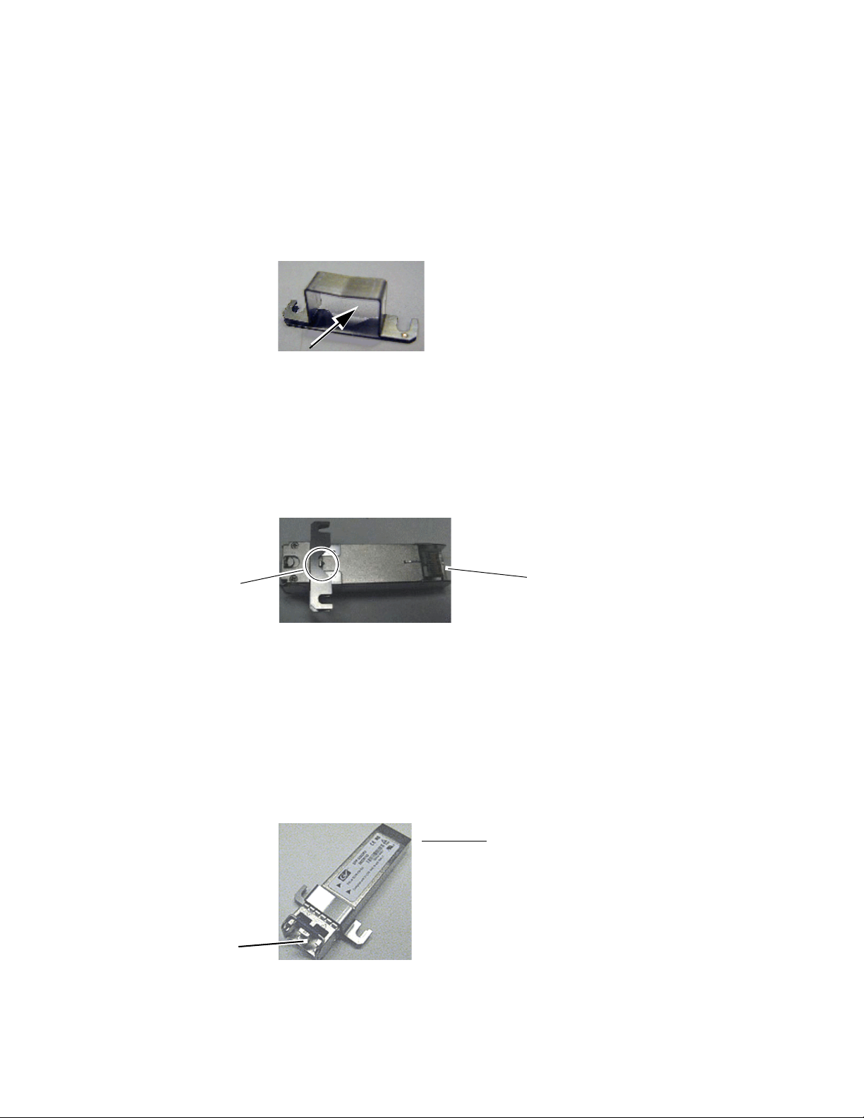
Mount Metal Bracket to Submodule
Attach the mounting bracket to the SFP submodule as shown below.
1. Insert the narrow end (SCA-2 connector) of the submodule into the
mounting bracket, label side up with the open slots on the bracket
pointing to the rear as shown by the direction of the arrow in Figure 3.
Figure 3. Mounting Bracket
2. Attach the mounting bracket to the submodule by sliding the bottom
part of the bracket as far as it will go (Figure 4) on the bottom side of the
submodule to hold it in place without forcing it. Make sure the open
bracket slots point towards the SCA-2 (electrical) connector on the
submodule.
Figure 4. Attach Bottom of Bracket to Submodule
3. The finished installation should look like the example in Figure 5. The
label will list the GV Model number, the GV part number, and the
manufacturer’s part number. Also note the two arrows on the label will
indicate signal direction as shown in the dual receiver example in
Figure 5 (arrows pointing in). A dual transmitter will have two arrows
pointing out, and a transceiver will have one input and one output
arrow.
Figure 5. Finished Bracket Mounting
8943RDA/-D/-DFR — Instruction Manual 15
Page 16
Installation
Fiber 1 and Fiber 2 connector
Bracket Straps
Slide submodule straps under
screws and tighten.
Insert end of submodule
into SCA-2 connector.
Screws
Submodule
SCA-2 Connector
8592_12r1
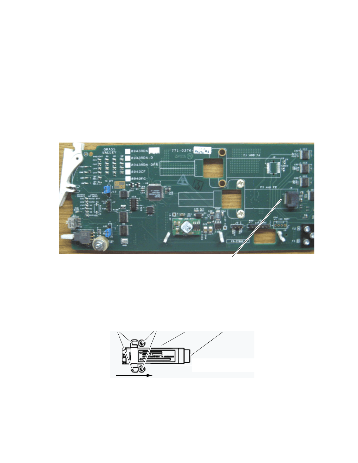
Installing SFP Submodule on Front Module
Refer to the instructions below for installing a single SFP fiber optic submodule for Fiber 1 and Fiber 2.
1. Remove any dust cover plugs from the submodule.
2. On the top (component) side of the front module circuit board, locate
the two screws and the SCA-2 connector in the bottom connector where
the submodule will be installed as shown in Figure 6.
Note On some modules, this may be labeled F3 and F4.
Figure 6. Location of Fiber 1 and Fiber 2 SFP Submodule
3. Loosen the two screws on the printed circuit board slightly so you can
slide the bracket straps underneath the screws and the SCA-2 connector
end of the submodule slides over the SCA-2 connector as shown in the
drawing in Figure 7.
Figure 7. Installing Strap-Mount SFP Submodule
16 8943RDA/-D/-DFR — Instruction Manual
Page 17
Installation
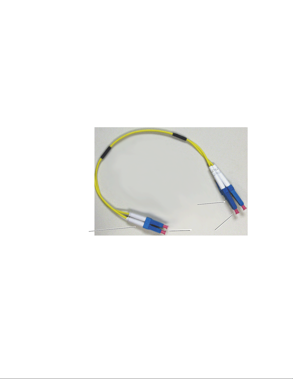
Ferrule covers
Duplex end
Simplex ends
4. Once the submodule is seated into the SCA-2 connector and the straps
are completely under the screws, tighten the screws to hold the
submodule in place.
Installing Fiber Jumper Cable Assembly
Before installing the fiber jumper cable assembly (Figure 8), remove the
protective ferrule covers and clean all fiber optic surfaces on the duplex and
simplex ferrule ends of the 2-channel fiber jumper cable assembly and the
submodule connector.
Use a standard fiber optic cleaning kit as described in Fiber Optic Cleaning
Requirement on page 21.
Figure 8. 2-Channel Fiber Jumper Cable Assembly
8943RDA/-D/-DFR — Instruction Manual 17
Page 18
Installation
Duplex cable end
Simplex cable ends
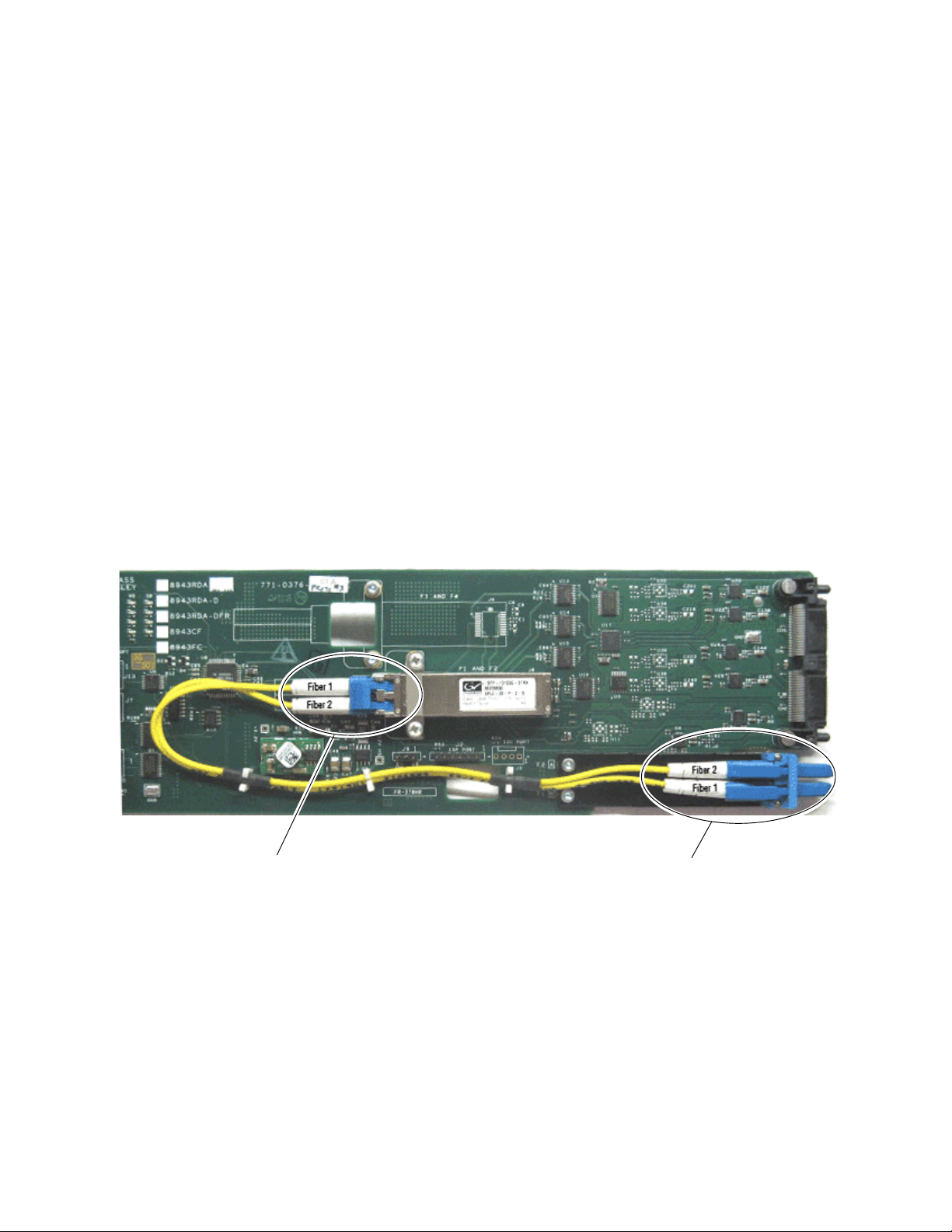
Refer to the drawing in Figure 9 for the following steps:
1. Carefully slide the duplex ferrule end of the 2-channel fiber jumper
cable assembly into the end of the submodule until the duplex
connector snaps into place.
2. Guide the two fiber jumper cables around towards the front of the
board and slip them through the plastic cable guides to hold them in
place.
3. Find the ferrule end of the simplex (single) fiber jumper cable that
corresponds to the top duplex cable (labeled fiber 1 in the photo) and
connect it to the bottom of the rear fiber connector (labeled Fiber 1 in the
photo).
4. Find the ferrule end of the simplex (single) fiber jumper cable that
corresponds to the bottom duplex cable (labeled Fiber 2 in the photo)
and connect it to the bottom (labeled Fiber 2 in the photo) of the rear
fiber connector.
5. Also refer to Figure 13 on page 24 for an illustration of the fiber
connector on the rear module.
Figure 9. Installing Fiber Jumper Cables
18 8943RDA/-D/-DFR — Instruction Manual
Page 19

Front Module Installation
After installing the rear module and the fiber optic submodule option if
being used, install the front module as follows:
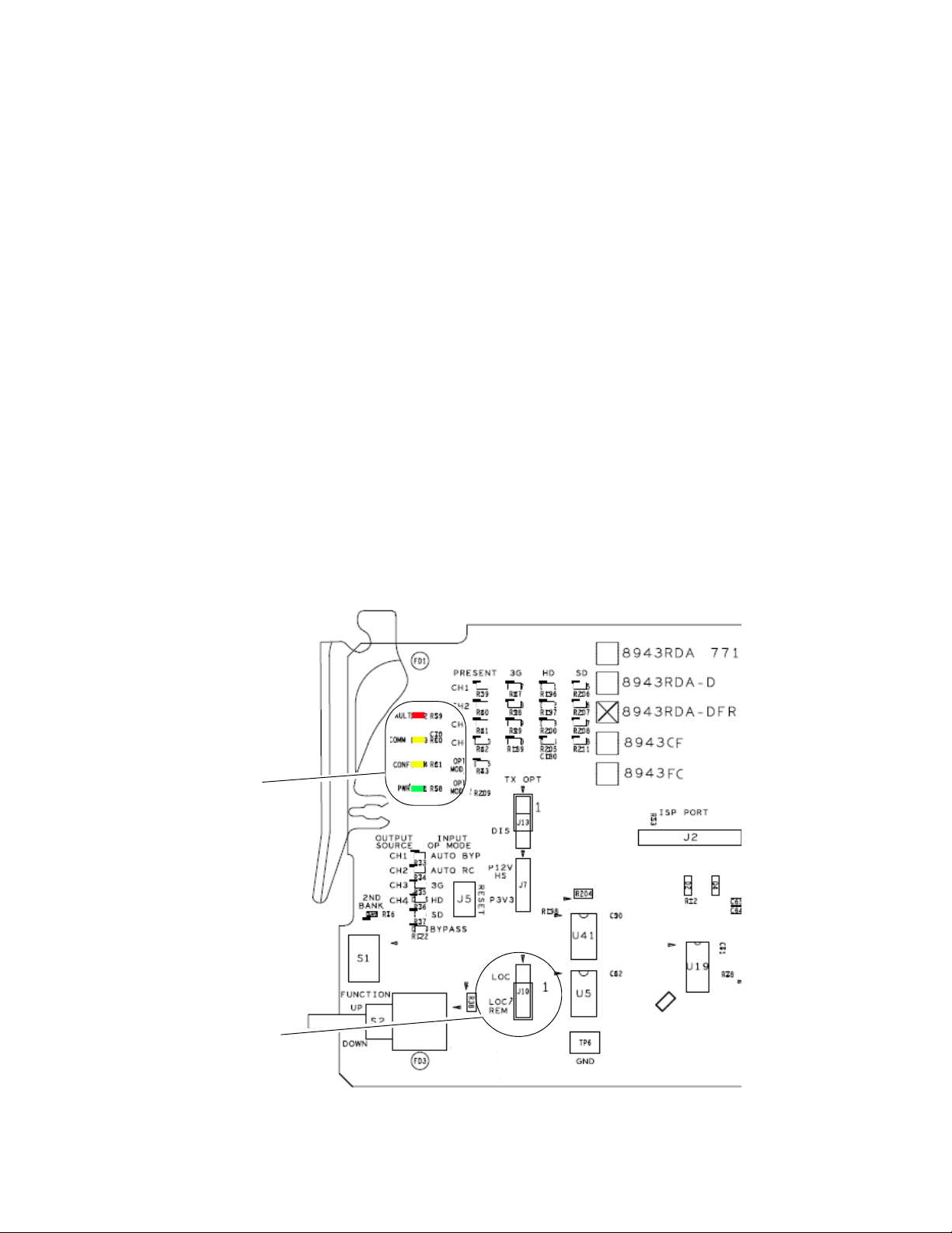
1. On the top of the front module, locate the LOC and LOC/REM jumper,
J10, shown in Figure 19 on page 42.
2. Set jumper J10 to LOC (pins 1-2) to lock out remote control, or
LOC/REM (pins 2-3), the default, for both local and remote control.
3. For 8943RDA-DFR modules using Dual Transmitter or Transceiver
fiber optic submodules: If you have installed an optional dual fiber
transmitter or transceiver submodule on your 8943RDA-DFR front
module, you must enable the transmitter output(s) by setting jumper,
J13 on the circuit board to pins 1-2, as shown in Figure 15 on page 33.
4. Locate the front slot corresponding to the rear module already
installed.
5. Insert the front module so that the circuit board slides through the
guides on the right side the slot (Figure 10 on page 20).
Installation
6. Carefully slide the module into the rear connector, making sure the
fiber optic connector fits into the rear module properly.
7. Lock the front module ejector tab into the locking pin.
8. Replace the frame front cover during operation to maintain optimum
cooling conditions.
8943RDA/-D/-DFR — Instruction Manual 19
Page 20
Installation
Slide circuit board through top
and bottom guides on right of slot.
Module installed
Locking Pin
Rear Connector
Bottom (solder side)
SFP Submodule mounted on top
(component) side (not visable in this view)
8592_09r0
Figure 10. Front Module Installation (8943RDA-DFR Shown)
20 8943RDA/-D/-DFR — Instruction Manual
Page 21

Cabling
Fiber Optic Cleaning Requirement
Cabling
Cabling to the 8943RDA and 8943RDA-D is done on the BNCs on the
89003E-R rear module. Cabling for the 8943RDA-DFR module is done on
the BNCs and optional fiber inputs and outputs as described in these sec
tions:
• 8943RDA Module Cabling on page 22
• 8943RDA-D Module Cabling on page 23
• 8943RDA-DFR Module Cabling on page 24
Before making any fiber optic cable mating connections (including submodule installation) and after every de-mating cycle, use an industry standard fiber optic cleaning kit, including oil-free compressed air, to clean the
fiber connectors and the connectorized fiber end faces. This helps ensure
optimum performance of the fiber optic interface. Industry standard fiber
optic cleaning kits can be purchased on the web and in electronics stores.
-
Video Input(s)
The 8943RDA modules will accept any of the SD/HD/3G- SDI video and
DVB ASI standards listed in the input specifications in
For the 8943RDA-DFR, the video input(s) to the module can be selected
from the following four sources, depending on the presence and type of
fiber optic submodule option installed:
• Electrical BNC J10 and BNC J8 (BNC J8 8943RDA-DFR only),
• Fiber RX 2 (when dual receiver or transceiver submodule is installed),
or
• Fiber Input RX 1 or RX 2 (with dual receiver submodule installed).
All input sources can be connected and active at the same time. Each active
input must be mapped to the desired output pair(s). Video input to video
output pair mapping is done in configuration using the local onboard con
trols, Settings web page, or Newton control panel (page 28).
Ta bl e 10 on page 82.
-
8943RDA/-D/-DFR — Instruction Manual 21
Page 22
Cabling
Video Outputs
The 8943RDA model outputs conform to the video standards listed in the
output specifications in
are available in four pairs, J1/J2, J3/J4, J5/J6, J7/J8 (J7 only for the
8943RDA-DFR). Fiber optic outputs available (Fiber 1 and Fiber 2) depend
on the type of fiber optic submodule installed. Two Fiber optic outputs are
available when a dual transmitter fiber optic submodule is installed and
one fiber optic output (TX1) is available when a transceiver is installed.
Video input to video output pair(s) mapping is done in configuration using
the local onboard controls, Settings web page, or Newton control panel
page 28).
(
Electrical outputs are always enabled. Fiber optic outputs on the
8943RDA-DFR module must be enabled in configuration using the local
onboard controls, Settings web page, or Newton control panel (
8943RDA Module Cabling
Ta bl e 10 on page 82. The electrical video outputs
page 28).
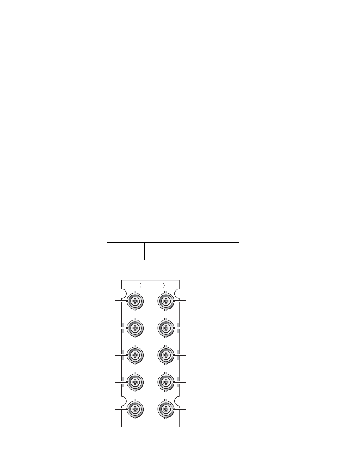
The 8943RDA front module requires the 89003E-R rear module. This
module has one electrical input to eight electrical BNC outputs. Refer to
Ta bl e 2 and Figure 11 for 89003E-R cabling information.
Table 2. Cabling Inputs and Outputs for 8943RDA Module
Signal Input Outputs Available
J9 BNC BNC Pairs: J1/J2, J3/J4, J5/J6, J7/J8:
Figure 11. 8943RDA Cabling on 89003E-R Module
89003E-R
J1 J2
Out
J3 J4
Out
J5 J6
Out
J7 J8
Out
Out
Out
Out
Out
J9 J10
In
8592_01r0
Not Used
22 8943RDA/-D/-DFR — Instruction Manual
Page 23
8943RDA-D Module Cabling
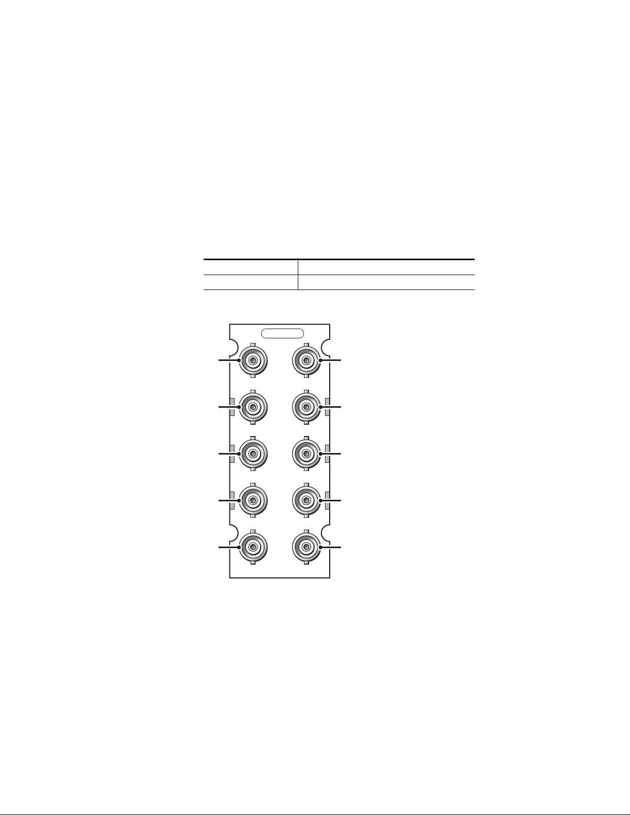
The 8943RDA-D front module requires the 89003E-R rear module. Two
electrical inputs are available and each may be assigned to any of the four
output pairs in configuration. An output pair may only have one input
assigned.
For example, BNC J9 can be assigned (mapped) to output pairs J1/J2 and
J3/J4 and BNC J8 can be assigned to output pairs J5/J6 and J7/J8. Video
input to video output pair(s) mapping is done in configuration using the
local onboard controls, Settings web page, or Newton control panel
page 28). Refer to Tab le 3 and Figure 12 for 89003E-R cabling information.
(
Table 3. Cabling Inputs and Outputs for 8943RDA-D Module
Signal Inputs Outputs Available
J9 BNC and J10 BNC BNC pairs: J1/J2, J3/J4, J5/J6, J7/J8
Figure 12. 8943RDA-D Cabling on 89003E-R Module
89003E-R
J1 J2
Out
Cabling
Out
Out
Out
Out
In
J3 J4
Out
J5 J6
Out
J7 J8
Out
J9 J10
In
8952_02r0
8943RDA/-D/-DFR — Instruction Manual 23
Page 24
Cabling
8943RDA-DFR Module Cabling
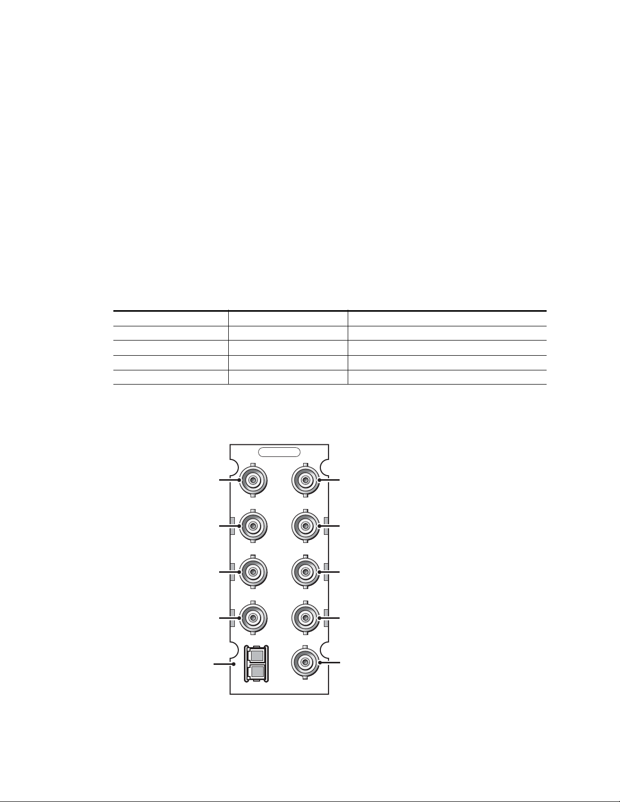
The 8943RDA-DFR requires the 89003FR-R rear module with electrical
inputs and outputs and a fiber optic connector for connection of fiber
inputs and outputs depending on the type of fiber optic option submodule
installed.
If using an optional fiber optic submodule, it must be installed on the front
of the 8943RDA-DFR front module. Fiber optic submodule types available
are listed with installation instructions in
(8943RDA-DFR only) on page 14.
Electrical and fiber video input to electrical video output pair and fiber
output mapping is done in configuration using the local onboard controls,
Settings web page, or Newton control panel (
Refer to Tab le 4 and Figure 13 for 89003FR-R cabling information.
Table 4. 8943RDA-DFR Cabling for 89003FR-R and Fiber Optic Connections
Fiber Optic Submodule Input(s) Available Outputs Available
None BNC J10, BNC J8 BNC pairs: J1/J2, J3/4, J5/J6, J7
Dual Fiber Receiver BNC J10, BNC J8, Fiber 1, Fiber 2
Dual Fiber Transmitter BNC J10, BNC J8 BNC pairs: J1/J2, J3/4, J5/J6, J7, Fiber Out 1, and Fiber Out 2
Fiber Transceiver BNC J10, BNC J8, Fiber In 2
1
Input to output pair assignment is made on Settings web page where Fiber inputs must be enabled.
2
Input to output pair assignment is made on Settings web page where Fiber outputs must be enabled.
1
Fiber Optics Submodule Installation
page 28).
1
BNC pairs: J1/J2, J3/4, J5/J6, J7
BNC pairs: J1/J2, J3/4, J5/J6, J7, and Fiber Out 1
2
2
Figure 13. 8943RDA-DFR Cabling on 89003FR-FR Rear Module
89003FR-R
J1 J2
Out
Out
Out
Out
Fiber I/O
Connector
2
1
FIBER
J3 J4
J5 J6
J7
J8
J10
Out
Out
Out
In
In
8592_03r0
24 8943RDA/-D/-DFR — Instruction Manual
Page 25
Power Up
Jumper J10 set for LOC/REM
Common LEDs
Operation Indicator LEDs
Power Up
Upon power-up, the green PWR LED should light and the CONFIG,
FAULT and COMM LEDs should illuminate during the module initializa
tion.
Note When a module is first plugged into a GeckoFlex frame, the 8900NET module
(if present) may report a momentary fault. This will clear once the module has
booted up.
The LEDs common to all modules (FAULT, COMM, CONFIG and PWR) are
highlighted in
version.
Refer to Ta bl e 5 on page 26 to see a complete list of possible operating conditions and the resulting indicator status. A red FAULT LED indicates an
error situation and, when noted with the other indicator LEDs, can indicate
a specific problem area. The presence of some LEDs on the module
depends on which model type you are using.
Figure 14 and operate in the same manner for each module
-
Figure 14. 8943RDA Front Module Indicator LEDs
8943RDA/-D/-DFR — Instruction Manual 25
Page 26

Power Up
LED Indication Condition
FAULT
(red)
COMM
(yellow)
CONFIG
(yellow)
PWR
(green)
CH 1-4 PRESENT
(Green)
CH 1-4 3G
(Blue)
CH 1-4 HD
(Yellow)
CH 1-4 SD
(Yellow)
OPT MOD_1
(Yellow)
(8943RDA-DFR only)
OPT MOD_2
(Yellow)
Refer to Tab le 5 for a description of each front edge LED and how it operates. LEDs present on specific module are illustrated in the figures listed
below.
Note Some LEDs, such as the FAULT LED, must report a collective state for all four
channels. This collective state is outlined in Table 6 on page 27.
• 8943RDA (Figure 19 on page 42)
• 8943RDA-D (Figure 24 on page 52)
• 8943RDA-DFR (Figure 28 on page 61)
Tab l e 5 . F r o nt Edge LED Indicators
STATUS LEDS
Off Collective module state of pass
On continuously Collective state of internal fault
Flashing Collective state of warning
Off No activity on frame communication bus
Double flash Location Command received by the module from a remote control system
Continuous short flash Activity present on the frame communication bus
Off No configuration change is in process, initialization complete
On Module is initializing or changing operating modes
Double flash
Off No power to module or module’s DC/DC converter failed
On continuously Normal operation, module is powered
Off No carrier
On Continuously Energized signal present
Off Signal present on CH 1-4 input is not detected as 3 Gb/s (carrier is way off frequency)
Flashing Occurs when the mode is set to manual bypass
On Continuously Signal present on CH 1-4 input is detected as 3 Gb/s
Off
Flashing Occurs when the mode is set to manual bypass
On Continuously Signal present on CH 1-4 input is detected as 1.485 Gb/s
Off Signal present on CH 1-4 input is not 1.485 (carrier is way off in frequency)
Flashing Occurs when the mode is set to manual bypass
On Continuously Signal present on CH 1-4 input is detected as 270 Mb/s
Off
On Continuously
Flashing An unsupported SFP submodule is installed in the top SFP position
Off
On
In unison with COMM LED, Location Command received by the module from a remote
control system
Signal present on CH 1-4 input is not detected as 1.485 Gb/s (carrier is way off frequency)
No SFP fiber optic submodule is installed or the SFP installed in the first SFP position
has a fault as noted on Status web page
A supported SFP submodule is installed in the top SFP position (see Table 1 on page 14)
for supported types)
Not used in this version
26 8943RDA/-D/-DFR — Instruction Manual
Page 27

Tab l e 5 . F r o nt Edge LED Indicators
LED Indication Condition
STATUS LEDS
MODULE LOCAL CONFIGURATION LEDS
CH 1-4 OUTPUT SOURCE
(Yellow)
CH 1-4 INPUT OP MODE
(Yellow)
On or Off Refer to Local Onboard Configuration on page 33
On or Off Refer to Local Onboard Configuration on page 33
Collective Module Status Reporting
Some status and fault reporting to the module level has only one status
indicator, such as the Status LED on each web page. This status indicator
must reflect the collective status of all four channels.
the collective input status will be for each channel state given below.
Table 6. Collective Input Status
CH 1
Input Status
Not Monitored Not Monitored Not Monitored Not Monitored Not Monitored
Not Present N/A N/A N/A Not Present
N/A Not Present N/A N/A Not Present
N/A N/A Not Present N/A Not Present
N/A N/A N/A Not Present Not Present
Present Not Monitored Not Monitored Not Monitored Present
Not Monitored Present Not Monitored Not Monitored Present
Not Monitored Not Monitored Present Not Monitored Present
Not Monitored Not Monitored Not Monitored Present Present
Present Present Not Monitored Not Monitored Present
Present Not Monitored Present Not Monitored Present
Present Not Monitored Not Monitored Present Present
Not Monitored Present Present Not Monitored Present
Not Monitored Present Not Monitored Present Present
Not Monitored Not Monitored Present Present Present
Present Present Present Not Monitored Present
Present Present Not Monitored Present Present
Present Not Monitored Present Present Present
Not Monitored Present Present Present Present
Present Present Present Present Present
CH 2
Input Status
CH 3
Input Status
CH 4
Input Status
Ta bl e 6 describes what
Collective Input Status
Power Up
8943RDA/-D/-DFR — Instruction Manual 27
Page 28

Configuration
Configuration
Configuration Summary
The 8943RDA modules can be configured locally using onboard switches
or remotely using the 8900NET network interface GUI or a networked
Newton Control Panel.
Refer to the following sections for a summary of configuration instructions:
• Configuration Summary (page 28)
• Local Onboard Module Configuration (page 33)
• Remote Control and Monitoring (page 38)
Operation of these control types is explained in detail in their respective
sections of this manual.
The configuration of each 8943RDA DA establishes:
• Input signal status reporting at module level (remote control only),
• Local only or Remote/Local control (onboard jumper selection),
• Input to output mapping (8943RDA-D and 8943RDA-DFR only), and
• Input Operating Mode setup.
Ta bl e 14 on page 89 provides a summary in table format of all parameters
and their ranges, default values, and remote, local, and control panel function names and locations for setting each value.
Input Operating Modes
The choices for input operating modes are described below. Refer to Tab le 7
on page 30 for an overview of the input status states in each of these modes.
Auto Reclock/Bypass
In this mode the electrical inputs are equalized and fed to the reclocker. The
module will analyze the input to determine whether the bit rate is
270Mb/s, 1485Mb/s, or 2970Mb/s. If the input signal matches one of these
rates, the signal is reclocked at the determined data rate and passed to the
electrical output line drivers. If the signal is determined to not be one of
these rates, the reclocker will be automatically bypassed and the signal
passed directly to the electrical output line drivers.
Note When in Auto Reclock/Bypass mode, the electrical line driver outputs will be
set to the last known good SD or HD slope (slew rate).
28 8943RDA/-D/-DFR — Instruction Manual
Page 29

Configuration
Auto Reclock/Mute
In this mode the electrical inputs are equalized and fed to the reclocker. The
module will analyze the input to determine whether the bit rate is 270Mb/s
(SD), 1485Mb/s (HD), or 2970Mb/s (3G). If the input signal matches one of
these rates, the signal is reclocked at the determined data rate and passed
to the electrical output line drivers. If the signal is determined to not be one
of these rates, the electrical outputs of the reclocker will be muted and the
outputs of the cable driver will be static.
3G 2970M
In this fixed reclock 3G mute mode, the inputs are equalized and fed to the
reclocker. The module will analyze the input to determine if the bit rate is
2970Mb/s (3G). If it is, the module will reclock the signal at 2970Mb/s and
feed it to the electrical output drivers. If the signal is determined not to be
2970Mb/s, the electrical outputs of the reclocker will be muted and the
cable driver outputs will be static.
HD 1485M
In this fixed reclock HD mute mode, the inputs are equalized and fed to the
reclocker. The module will analyses the input to determine if the bit rate is
1485Mb/s. (HD) If it is, the module will reclock the signal at 1485b/s and
feed it to the electrical output drivers. If the signal is determined not to be
1485Mb/s, the electrical outputs of the reclocker will be muted and the
cable driver outputs will be static.
SD 270M
In this fixed reclock SD mute mode, the inputs are equalized and fed to the
reclocker. The module will analyze the input to determine if the bit rate is
270Mb/s (SD). If it is, the module will reclock the signal at 270Mb/s and
feed it to the electrical output drivers. If the signal is determined not to be
270Mb/s, the electrical outputs of the reclocker will be muted and the cable
driver outputs will be static.
Manual Bypass HD/3G
In this mode, the inputs are equalized and the reclocker is always bypassed.
This selection should be made when using a 1485Mb/s or 2970Mb/s data
rate or data so that the output drivers will be set to the proper slew rate
(slope) for HD signals.
Manual Bypass SD
In this mode, the inputs are equalized and the reclocker is always bypassed.
This selection should be made when using a 270Mb/s data rate or to pass
data so that the output drivers will be set to the proper slew rate (slope) for
SD signals.
8943RDA/-D/-DFR — Instruction Manual 29
Page 30

Configuration
Ta bl e 7 gives an overall summary of the conditions of the signal output
states, the status reporting LEDs on the module circuit board, and status
messages on the web pages that will result when the input signal is
Not Present, or Unknown in each of the operating modes. The conditions are the
same for Channels 1-4 and will be reported separately for each channel.
Table 7. Reported Input Status Summary
Operating
Mode
Auto Reclock/Bypass Not Present Off Off Off Off
Auto Reclock/Bypass
Auto Reclock/Bypass 2970M Green Blue Off Off
Auto Reclock/Bypass 1485M Green Off Yellow Off
Auto Reclock/Bypass 270M Green Off Off Yellow
Auto Reclock/Mute Not Present Off Off Off Off Muted N/A
Auto Reclock/Mute
Auto Reclock/Mute 2970M Green Blue Off Off
Auto Reclock/Mute 1485M Green Off Yellow Off
Auto Reclock/Mute 270M Green Off Off Yellow
3G 2970M Not Present Off Off Off Off Muted HD
3G 2970M Not 2970M Green Off Off Off Muted HD
3G 2970M 2970M Green Blue Off Off
HD 1485M Not Present Off Off Off Off Muted HD
HD 1485M Not 1485M Green Off Off Off Muted HD
HD 1485M 1485M Green Off Yellow Off
SD 270M Not Present Off Off Off Off Muted SD
SD 270M Not 270M Green Off Off Off Muted SD
Rate
Detected
Unknown (not 270M,
1485M, or 2970M)
Unknown (not 270M,
1485M, or 2970M)
PRESENT
LED
Green Off Off Off
Green Off Off Off Muted N/A
3G
LEDHDLEDSDLED
Output
Signal
Muted
(Noise)
Input
Signal
Reclocked
2970M
Reclocked
1485M
Reclocked
270M
Reclocked
2970M
Reclocked
1485M
Reclocked
270M
Reclocked
2970M
Reclocked
1485M
Output
Slope
See
Note
HD
HD
SD
HD
HD
Reporting
Enabled
No Not Monitored
Yes Signal Not Present
No Not Monitored
Yes Signal Present
No Not Monitored
1
Yes Signal Present
No Not Monitored
Yes Signal Present
No Not Monitored
Yes Signal Present
No Not Monitored
Yes Signal Not Present
No Not Monitored
Yes Signal Not Present
No Not Monitored
Yes Signal Present
No Not Monitored
Yes Signal Present
No Not Monitored
Yes Signal Present
No Not Monitored
Yes Signal Not Present
No Not Monitored
Yes Signal Not Present
No Not Monitored
Yes Signal Present
No Not Monitored
Yes Signal Not Present
No Not Monitored
Yes Signal Not Present
No Not Monitored
Yes Signal Present
No Not Monitored
Yes Not Present
No Not Monitored
Yes Signal Not Present
Present,
Signal State
30 8943RDA/-D/-DFR — Instruction Manual
Page 31

Table 7. Reported Input Status Summary
Operating
Mode
SD 270M SD 270M Green Off Off Yellow
Manual Bypass HD/3G Not Present Off Off Off Off N/A HD
Manual Bypass HD/3G 2970M or 1485M Green Flash Flash Off
Manual Bypass HD/3G
Manual Bypass SD Not Present Off Off Off Off N/A SD
Manual Bypass SD 270M Green Off Off Flash
Manual Bypass SD Not 270M Green Off Off Off
1
When in Auto/Reclock/Bypass mode, the electrical line driver outputs will be set to the last known good SD or HD slope (slew rate).
Rate
Detected
Not 2970M or
1485M
PRESENT
LED
Green Off Off Off
3G
LED
HD
LEDSDLED
Output
Signal
Reclocked
270M
Input
Signal
Input Signal
(with data)
Input
Signal
Input Signal
(with data)
Output
Slope
SD
HD
HD
SD
SD
Configuration
Reporting
Enabled
No Not Monitored
Yes Signal Present
No Not Monitored
Yes Signal Not Present
No Not Monitored
Yes Signal Present
No Not Monitored
Yes Signal Present
No Not Monitored
Yes Signal Not Present
No Not Monitored
Yes Signal Present
No Not Monitored
Yes Signal Present
Signal State
8943RDA/-D/-DFR — Instruction Manual 31
Page 32

Configuration
Input to Output Mapping
Another configuration parameter available with the 8943RDA-D and the
8943RDA-DFR is the input to output mapping capability. Any available
input channel can be routed (mapped in configuration) to any available
output through the internal crosspoint structure. This crosspoint mapping
configuration allows flexibility in choosing what input channels feed what
output pairs.
The 8943RDA-D input channel sources, CH1 (Coax J9) and CH2 (Coax J10)
can be mapped to any of the four coaxial output pairs, J1/J2, J3/J4, J5/J6,
and J7/J8. For example, the input source on CH1 can be mapped to feed
output pair J1/J2 and the input source on CH2 can be mapped to feed
output pairs J3/J4, J5/J6, and J7/J8.
In the case of the 8943RDA-DFR, input channel sources are CH1 (Coax J10),
CH2 (Coax J8), CH3 (Fiber 1), and CH4 (Fiber 2). Fiber input channels and
outputs are available depending on the type of SFP fiber optic submodule
option installed. Fiber inputs and outputs must be enabled in configura
tion. Refer to Tab le 1 on page 14 for a list of the fiber optic submodule
option models available.
-
8943RDA-DFR input to output mapping with the available SFP fiber optic
submodules is summarized in
Tab le 8. Also refer to the block diagrams
starting on page 86 for an illustration of each 8943RDA-DFR configuration.
Table 8. 8943RDA-DFR Input to Output Mapping
Fiber Optic
Submodule
None
Dual Fiber Receiver
Dual Fiber Transmitter
Transceiver
1
Input to output pair assignment is made on Settings web page where Fiber inputs must be enabled.
2
Input to output pair assignment is made on Settings web page where Fiber outputs must be enabled.
Input(s)
Available
CH1 (BNC J10)
CH2 (BNC J8)
CH1 (BNC J10)
CH2 (BNC J8)
CH3 (Fiber 1)
CH4 (Fiber 2)
CH1 (BNC J10)
CH2 (BNC J8)
CH1 (BNC J10)
CH2 (BNC J8)
CH 3 (Fiber In 2
Outputs Available
BNC pairs: J1/J2, J3/4, J5/J6, J7 (single output)
1
1
1
BNC pairs: J1/J2, J3/4, J5/J6, J7 (single output)
BNC pairs: J1/J2, J3/4, J5/J6, J7 (single output), Fiber Out 1,
and Fiber Out 2
BNC pairs: J1/J2, J3/4, J5/J6, J7 (single output), and Fiber Out 1
2
2
32 8943RDA/-D/-DFR — Instruction Manual
Page 33

Local Onboard Configuration
Silkscreen on back
of module corresponding
to settings on S1.
Set jumper J13 to pins 1-2
to enable fiber TX outputs
(8943RDA-DFR only).
Local onboard configuration can be done for the following:
• CH1-4 OUTPUT OP MODE – set the output operating mode for each available
channel (Set INPUT OP MODE on page 35), and
CH1-4 OUTPUT SOURCE – set input source to each available output (Set
•
OUTPUT SOURCE on page 36).
Enable TX Outputs (8943RDA-DFR only) – when a dual transmitter or trans-
•
ceiver fiber optic submodule is installed on the 8943RDA-DFR, the
output(s) must be enabled by setting jumper J13, TX OPT, to pins 1-2.
Setting jumper J13 to pins 2-3 disables the transmitter outputs.
Local onboard controls include two switches: the FUNCTION rotary
switch, S1, and the paddle switch, S2, on the front edge of the module.
These are used in conjunction with the OUTPUT SOURCE and INPUT OP
MODE LEDs shown on the right of
The parameters coordinating to the FUNCTION switch settings are silkscreened on the back of the module as shown on the left of Figure 15.
Configuration
Figure 15.
Use the figure below and the settings in Ta bl e 9 on page 34 to set each of the
module parameters.
Figure 15. Local Onboard Controls Rear Silkscreen and Front LEDs
8943RDA/-D/-DFR — Instruction Manual 33
Page 34

Configuration
Function
Position
Input Op Mode
Source Select
1
Presence of CH3 Fiber 1 input requires an optional Dual Receiver submodule.
2
Presence of CH4 Fiber 2 input requires an optional Dual Receiver or Transceiver submodule.
3
Presence of Fiber 1 TX output requires an optional Dual Transmitter submodule.
4
Presence of Fiber 2 TX output requires an optional Dual Transmitter or Transceiver submodule.
Table 9. Local Onboard Configuration Functions
Paddle
Switch
Switch
Up
0 – – Neutral position. Leave S1 in this position during normal operation.
1
2 Set Input Operation Mode for Channel 2
3 Set Input Operation Mode for Channel 3 (8943RDA-DFR only)
4 Set Input Operation Mode for Channel 4 (8943RDA-DFR only)
5
6 Select input source to coax output pair J3/J4
7 Select input source to coax output pair J5/J6
8
9 Select input source to Fiber 1
A Select input source to Fiber 2 4 TX output (8943RDA-DFR only)
B Enable Disable Channel 1 reporting
C Enable Disable Channel 2 reporting
D Enable Disable Channel 3 reporting
E Enable Disable Channel 4 reporting
F Recall Recall Factory Defaults
CH1 (J9 for 8943RDA/-D and J10 for 8943RDA-DFR)),
CH2 (J10 for 8943RDA-D or J8 for 8943RDA-DFR),
CH3 (Fiber 1 input
or CH4 (Fiber 2 input 2 8943RDA-DFR only)
AUTO BYP,
AUTO RC,
BYPASS
Paddle
Switch
Down
3G,
HD,
SD, or
1
8943RDA-DFR only),
Function Description
Set Input Operation Mode for Channel 1
Select input source to coax output pair J1/J2
Select input source to coax output pair J7/J8 (8943RDA-D) or
select input source to single coax output J7 (8943RDA-DFR)
3
TX output (8943RDA-DFR only)
34 8943RDA/-D/-DFR — Instruction Manual
Page 35

Set INPUT OP MODE
To set the INPUT OP MODE for each available channel, do the following:
1. CH1 OP MODE (all models): Using a small flat blade screwdriver or an
adjustment tool, move the FUNCTION rotary switch to position
shown in Tab le 9 on pag e 3 4, this is the position for setting the INPUT
OP MODE for CH1.
Use the paddle switch, S2, to move up and down through the following
available INPUT OP MODE choices:
•AUTO BYP
•AUTO RC
•3G
•HD
•SD
•BYPASS
Each of these choices is described in detail in Input Operating Modes on
page 28. As the paddle switch is pressed, the corresponding INPUT OP
MODE yellow LED will light on the LED array, indicating which mode
is currently selected. Stop on the LED corresponding to the mode you
want.
2. CH2 OP MODE (8943RDA-D and 8943RDA-DFR) Set the Function rotary
switch to
scroll through to one of the choices listed in Step 1 above.
Configuration
1. As
2 to select the CH2 OP MODE. Use the paddle switch, S2, to
3. CH3 OP MODE (8943RDA-DFR) Set the Function rotary switch to 3 to select
the CH3 OP MODE. Use the paddle switch, S2, to scroll through to one
of the choices listed in Step 1 above.
4. CH4 OP MODE (8943RDA-DFR) Set the Function rotary switch to 4 to select
the CH4 OP MODE. Use the paddle switch, S2, to scroll through to one
of the choices listed in Step 1 above.
8943RDA/-D/-DFR — Instruction Manual 35
Page 36

Configuration
Set OUTPUT SOURCE
Input to output mapping is done by choosing an input channel to feed an
output coax pair or an optional fiber output (8943RDA-DFR only). This
setting is only done on the 8943RDA-D and the 8943RDA-DFR models.
Refer to
has only one input which is automatically mapped to all output pairs.
Output mapping is summarized in
To assign a source to an output, do the following:
1. J1-2 SOURCE: Rotate the Function rotary switch to position 5 to select the
Tab le 14 on page 89 for the factory default settings. The 8943RDA
input source to feed output coax pair J1/J2 from one of the following
sources:
• CH1 (Coax J9 for 8943RDA/-D or Coax J10 for 8943RDA-DFR)
• CH2 (Coax J10 for 8943RDA-D or Coax J8 for 8943RDA-DFR)
• CH3 (Fiber 1 input available when Dual Receiver SFP fiber optic
option is installed on 8943RDA-DFR only)
• CH4 (Fiber 2 input available when Dual Receiver or Transceiver
SFP fiber optic option installed on 8943RDA-DFR only)
Input to Output Mapping on page 32.
Use the paddle switch to move between channel choices, the OUTPUT
SOURCE LEDs will light indicating which channel is selected. Move
through the channels until the LED is highlighted for the input source
you want to feed J1-2 coax output pair.
2. J3-4 SOURCE: Set the Function rotary switch to 6 to select the input source
to feed output coax pair J3-4 in the same manner as Step 1 above.
3. J5-6 SOURCE: Set the Function rotary switch to 7 to select the input source
to feed output coax pair J5-6 in the same manner as Step 1 above.
4. J7-8 SOURCE: Set the Function rotary switch to 8 to select the input source
to feed output coax pair J7-8 (8943RDA-D) or J7 (8943RDA-DFR only)
in the same manner as Step 1 above.
5. FIBER1 SOURCE (8943RDA-DFR only): Set the Function rotary switch to 9 to
select the input source to feed the optional Fiber 1 output in the same
manner as Step 1 above. For Fiber 1 output presence, an optional dual
transmitter fiber submodule must be installed on the 8943RDA-DFR
front module and jumper J13 must be set to enable the transmitter
outputs (pins 2-3).
6. FIBER2 SOURCE (8943RDA-DFR only): Set the Function rotary switch to A to
select the input source to feed the optional Fiber 2 output
(8943RDA-DFR only) in the same manner as Step 1 above. For Fiber 2
output presence, an optional dual transmitter fiber submodule or a
transceiver fiber optic submodule (Fiber 1 input/Fiber 2 output) must
be installed on the 8943RDA-DFR front module and jumper J13 must be
set to enable the transmitter outputs (pins 2-3).
36 8943RDA/-D/-DFR — Instruction Manual
Page 37

Configuration
7. CHANNEL 1 REPORTING: Set the Function rotary switch to B and use the
paddle switch to enable (paddle up) or disable (paddle down)
Channel 1 reporting to the module level.
8. CHANNEL 2 REPORTING: Set the Function rotary switch to C and use the
paddle switch to enable (paddle up) or disable (paddle down)
Channel 2 reporting to the module level.
9. CHANNEL 3 REPORTING (8943RDA-DFR only): Set the Function rotary switch to
D and use the paddle switch to enable (paddle up) or disable (paddle
down) Channel 3 reporting to the module level.
10. CHANNEL 4 REPORTING (8943RDA-DFR only): Set the Function rotary switch to
E and use the paddle switch to enable (paddle up) or disable (paddle
down) Channel 4 reporting to the module level.
11. RECALL FACTORY DEFAULTS: Set the Function rotary switch to F and use the
paddle switch to recall factory defaults (paddle up).
8943RDA/-D/-DFR — Instruction Manual 37
Page 38

Configuration
Remote Configuration
The 8943RDA configuration and monitoring can also be performed using a
web browser GUI interface or a networked Newton Control Panel when
the 8900NET (Net Card) Network Interface module is present in the
GeckoFlex frame (8900FFN). Each of these interfaces is summarized below.
8900NET Module Information
Refer to the 8900NET Network Interface Module Instruction Manual available
online in PDF format for information on the 8900NET Network Interface
Module and setting up and operating the GeckoFlex 8900 frame network.
Note Upgrade software and instructions for the 8900NET can be downloaded from
the Grass Valley ftp and web sites.
Newton Control Panel Configuration
A Newton Control Panel (hard and/or soft version) can be interfaced to the
GeckoFlex frame over the local network. Refer to the documentation that
accompanies the Newton Modular Control System for installation, config
uration, and operation information.
-
Control panel access offers the following considerations for module configuration and monitoring:
• Ability to separate system level tasks from operation ones, minimizing
the potential for on-air mistakes.
• Ability to group modular products—regardless of their physical locations—into logical groups (channels) that you can easily manipulate
with user-configured knobs.
• Update software for applicable modules and assign frame and panel IP
addresses with the NetConfig Networking application.
• Recommended for real-time control of module configuration parameters, providing the fastest response time.
Note Not all module functions are available with the control panel, such as factory
default recalls.
38 8943RDA/-D/-DFR — Instruction Manual
Page 39

Configuration
An example of the Newton Configurator is shown in Figure 16. Newton
control parameters are given in Tab le 14 on page 89.
Figure 16. Newton Configurator Example
Web Browser Interface
The web browser interface provides a graphical representation of module
configuration and monitoring.
Use of the web interface offers the following considerations:
• Web access will require some normal network time delays for pro-
cessing of information.
• Configuration parameter changes may require pressing
Enter, upload processing time, and a manual screen refresh to become
effective.
• Web interface recommended for setting up module signal and slot
names, and reporting status for SNMP and monitoring.
Refer to the Frame Status web page shown in Figure 17 on page 40. The
8900 modules can be addressed by clicking either on a specific module icon
in the frame status display or on a module name or slot number in the link
list on the left.
Apply button or
8943RDA/-D/-DFR — Instruction Manual 39
Page 40

Configuration
Note The physical appearance of the graphics on the web pages shown in this
manual represent the use of a particular platform, browser and version of
8900NET module software. They are provided for reference only. Web pages
will differ depending on the type of platform and browser you are using and
the version of the 8900NET software installed in your system. This manual
reflects an 8900NET module with software version 4.3.0, using Internet
Explorer, the recommended web browser, and Windows XP operating
system.
For information on status and fault monitoring and reporting shown on the
module Status page, refer to
8943RDA Status Web Page on page 44, the
8943RDA-D Status Web Page on page 54, or the 8943RDA-DFR Status Web
Page on page 63.
Note Click on the Refresh button to update the web page after any changes.
Figure 17. Frame Status Web Page
The Links section lists the frame and its current modules. The selected link's Status
page is first displayed and the sub-list of links for the selection is opened. The sub-list
allows you to select a particular information page for the selected device.
Content display section
for the selected frame or module (frame slot icons are also
active links).
Refresh button for manual
update of page
displays the information page
8592_04r0
40 8943RDA/-D/-DFR — Instruction Manual
Page 41

8943RDA Module Links and Web Pages
The 8900 GUI provides the following links and web pages for the 8943RDA
modules (
• Status – reports input and output signals and frame bus communication status and module information including software version, hardware version, serial number, Asset Number (set on the Slot Config web
page,
• I/O Config – shows the rear connections for the 89003E-R rear module
(8943RDA and 8943RDA-D) and the 89003FR-R rear module
(8943RDA-DFR), and allows naming of each input and enabling and
disabling of input signal status reporting to the module level,
• Settings – allows the input to output mapping configuration of the
8943RDA-D and 8943RDA-DFR, and
• Slot Config – provides Locate Module and Slot Memory functions
along with links to the SNMP, LED Reporting, and Frame Alarm configuration web pages.
Figure 18). The links are the same for all models.
Configuration
The 8943RDA-DFR modules can use one of the various fiber optic submodules listed in Fiber Optics Submodule Installation (8943RDA-DFR only) on
page 14.
Figure 18. 8943RDA/-D/-DFR Web Page Links
Refer to the following pages for detailed web page descriptions for each of
the different model types listed below:
• 8943RDA (page 42)
• 8943RDA-D (page 52)
• 8943RDA-DFR (page 61)
8943RDA/-D/-DFR — Instruction Manual 41
Page 42

Configuration
8943RDA Module Configuration and Operation
The 8943RDA module uses the 89003E-F rear module and has one coax
input at BNC J9 that feeds eight coax outputs. For cabling instructions, see
8943RDA Module Cabling on page 22.
The status and configuration LEDs present on the 8943RDA module are
shown in
in Tab le 5 on page 26.
Figure 19. 8943RDA Front Module Indicator LEDs
Figure 19. These LEDs operate as described in the LED summary
42 8943RDA/-D/-DFR — Instruction Manual
Page 43

Configuration
Use
this
link
Local Configuration
Remote Configuration
Configuration
The 8943RDA can be configured using the front edge onboard controls or
using the remote controls available with a web browser or a networked
Newton Control Panel.
The only configuration is setting the Input Operating mode for Channel 1
on the Settings web page (
This module uses only one input channel (CH1) which feeds eight coax outputs. There is no input to output mapping required on this module.
For Local configuration, follow the summary of instructions given in Local
Onboard Configuration on page 33 for using the front edge onboard switches
for configuration.
8943RDA Settings Web Page on page 48).
The remote configuration is summarized in Remote Configuration on
page 38.
Each of the available web pages for the 8943RDA are shown on the following pages:
• Status (page 44)
• I/O Config (page 46)
• Settings (page 48)
• Slot Config (page 49)
8943RDA/-D/-DFR — Instruction Manual 43
Page 44

Use
this
link
Configuration
8943RDA Status Web Page
The Status web page (Figure 20 on page 45) for the 8943RDA shows the
signal status of the input signal(s) and communication status with the
frame bus. Color coding of
the display indicates the signal status.
In general, graphics and text col
• Green = Pass – signal or reference present, no problems detected.
Red = Fault – fault condition.
•
• Yellow = Warning – signal is absent, has errors, or is mis-configured.
• Gray = Not monitored.
Under the
and the slot location of the module in the frame.
The graphic shows the input and output s
Only input signal status is reported by color in this graphic. Outputs are not
monitored (always gray). The input signal status reporting for CH1 and
CH 2 can be disabled on the I/O Config web page.
The Status LED on each web page will
module. Refer to Collective Module Status Reporting on page 27.
Also shown is the rear and front module status. Information about the
ule, such as Part Number, Serial Number, Hardware Revision, Soft-
mod
ware Version, and Asset Tag number (ass
page) are given in table format at the bottom of the Status web page.
The area inside the double bars below the
sages reported from the module.
Status title are given the model description, the Frame location,
ors used indicate the following:
ignals available for the module.
display the collective status of the
igned on the Slot Config web
graphic will report warning mes-
Note The 8943RDA module software version can be either 1.0.4 or 1.1.0. The dif-
ference in software versions only affects the 8943RDA-DFR fiber optic submodule.
44 8943RDA/-D/-DFR — Instruction Manual
Page 45

Figure 20. 8943RDA Status Web Page
Configuration
8943RDA/-D/-DFR — Instruction Manual 45
Page 46

Use
this
link
Configuration
8943RDA I/O Config Web Page
Use the I/O Config web page to see an illustration of the 89003E-R rear
module as used with the 8943RDA, enab
reporting, and naming inputs. Refer to Figure 21 on page 47 for an illustration of the 8943RDA Status web page.
le or disable module level status
Rear Module Configuration
All of the input and output connectors on the corresponding 89003E-R rear
module are illustrated on the I/O Config web page.
The inputs can be configured with
Reporting Enabled – the status reporting of the video input at Coax J9 can be
enabled or disabled at the module level by selecting or de-selecting the corresponding checkbox in the
When the reporting is enabled, the input
color following the input status on the Status web page.
If monitoring is disabled, the area will appear in gray
monitored.
Note Status of the video outputs is not monitored in this application.
The enabling or disabling of this reporting will not affect upper level
reporting to the 8900NET (Net Card) or an SNMP monitoring system if
used.
Naming Input – a name can be assigned to the input signal for Ch 1 at Coax J9.
The name can be up to 15 characters.
Reporting Enabled column.
the following controls:
status can be also be monitored by
indicating it is not
46 8943RDA/-D/-DFR — Instruction Manual
Page 47

Figure 21. I8943RDA with 89003E-R Rear Module – I/O Config Web Page
Configuration
8943RDA/-D/-DFR — Instruction Manual 47
Page 48

Use
this
link
Configuration
8943RDA Settings Web Page
The Settings web page for 8943RDA-D (Figure 22) provides selection of the
input mode for BNC J9.
he input choices are as follows:
• Auto Reclock/Bypass,
Auto Reclock/Mute,
•
• 3G 2970M,
• HD 1485M,
• SD 270M,
• Manual Bypass HD/3G, or
•Manual Bypass SD.
For a full description of each of these modes, refer to the Modes Summary
Input Operating Modes on page 28.
The display will also report the
output signal is
selected), the display will also report
Figure 22. 8943RDA Settings Web Page
Not Present and has been muted (depending on the Mode
Rate Detected and the Signal State. If the
Mute.
48 8943RDA/-D/-DFR — Instruction Manual
Page 49

Use
this
link
Configuration
Slot Config Web Page (All Models)
Use the Slot Config web page shown in Figure 23 to perform the following
functions on the modules:
•Locate Module
Slot Identification
•
•Slot Memory
• Frame Health Reporting
• LED Reports
• SNMP Trap Reporting
The functionality of the Slot Config web
the 8943RDA series. Each of these functions is described in detail below.
Figure 23. 8943RDA Slot Config Web Page
page is the same for each model of
8943RDA/-D/-DFR — Instruction Manual 49
Page 50

Configuration
Locate Module
Selecting Flash from the Locate Module pulldown flashes the yellow COMM
and CONF LEDs on the front of the module so it can be located in the
frame.
Slot Identification
You may identify the module by typing a specific name in the Name field.
The assigned name is stored on the 8900NET module and travels with the
8900NET module if it is moved to another frame. Select
factory default module name.
An asset identification may be entered in the Asset Tag field. This will appear
on the module Status web page and in the NetConfig inventory report.
Default to enter the
Slot Memory
The slot configuration for each media module is automatically polled and
refreshed periodically (about every 50 minutes) by the 8900NET module
when the
page (with 4.3.0 software) and/or the
media module Slot Config web page is selected.
Always Slot Refresh checkbox on the 8900NET Configuration web
Restore upon Install checkbox on any
When the Restore upon Install checkbox on any media module Slot Config
web page has been selected, the current configuration from that module is
saved in slot memory on the 8900NET module. This allows the current
module to be removed and when another module of the same part number,
and software version is installed, the configuration saved to the 8900NET
module will be downloaded to the installed module. The
checkbox must be selected before the current module with the saved con
figuration is removed.
Note Make sure all modules of the same model type are running the same software
version and have the same part number silk-screened on the printed circuit
board. Downloading a configuration to a module with a different software
version or part number can produce unexpected results.
If a different type of module is installed in this slot, a warning message will
state that the original module type has been replaced with another module
type. In this case, a
configuration from the previous module.
You may also select the Learn Module Config button at any time to save the
current configuration for this slot. The configuration is saved on the
8900NET module. If the 8900NET module is removed or powered down,
the stored configurations are not saved.
Clear button will appear allowing you to clear the stored
Restore upon Install
-
50 8943RDA/-D/-DFR — Instruction Manual
Page 51

Configuration
When no Restore upon Install checkboxes on any of the media module Slot
Config web pages are selected and the
8900NET Configuration web page is unchecked, the slot refresh polling
function on the 8900NET module will be disabled. See the
checkbox description in the 8900NET (Net Card) Network Interface Module
Instruction Manual for more details.
Note Uncheck the Restore Upon Install button before downloading new software.
Always Slot Refresh checkbox on the
Always Slot Refresh
Frame Health Reporting
This web page allows configuration of the alarms and warnings that are
reported to the external Frame Health Alarm connector on the rear of the
GeckoFlex frame. Refer to 8900NET Instruction Manual for more details.
LED Reports Link
Select the LED Reports link to open the 8900NET LED Reporting web page.
Normally, every module in the frame will report to the 8900NET module
any Fault, Signal Loss, Reference Loss, or Config Error conditions. These
conditions will be reflected by the status LEDs on the 8900NET module.
Using this web page, any of these conditions can be disabled from being
reported to the 8900NET module for each individual module and other
components (power supplies, fans) in the frame
SNMP Trap Reports Link
Select the SNMP Trap Reports link to open the 8900NET SNMP Reporting
web page. This link will only be present when SNMP Agent software has
been installed on the 8900NET module. This web page allows configura
tion of which alarms and warnings that are reported to the SNMP management software.
Refer to the 8900NET Instruction Manual for complete details on using the
8900NET web pages.
-
8943RDA/-D/-DFR — Instruction Manual 51
Page 52

Configuration
8943RDA-D Module Configuration and Operation
The 8943RDA-D module uses the 89003E-F rear module and has two coax
inputs at BNC J9 and BNC J10 and four pairs of coax pair outputs. For
cabling instructions, see
The status and configuration LEDs present on the 8943RDA-D module are
shown in
in Tab le 5 on page 26.
Figure 24. 8943RDA Front Module Indicator LEDs
Figure 24. These LEDs operate as described in the LED summary
8943RDA-D Module Cabling on page 23.
52 8943RDA/-D/-DFR — Instruction Manual
Page 53

Configuration
Use
this
link
Local Configuration
Remote Configuration
Configuration
The 8943RDA-D can be configured using the front edge onboard controls
or using the remote controls available with a web browser or a networked
Newton Control Panel.
The Input Operating mode for Channel 1 and Channel 2 must be set on the
Settings web page.
This module two coax inputs channel (CH 1 and CH 2) which four sets of
output coax pairs. Inputs can be mapped to output pairs on the Settings
web page.
For Local configuration, follow the summary of instructions given in Local
Onboard Configuration on page 33 for using the front edge onboard switches
for configuration.
The remote configuration is summarized in Remote Configuration on
page 38.
For the 8943RDA-D module, each of the available web pages are shown on
the following pages:
• Status (page 54)
• I/O Config (page 56)
• Settings (page 58)
• Slot Config (page 60)
8943RDA/-D/-DFR — Instruction Manual 53
Page 54

Use
this
link
Configuration
8943RDA-D Status Web Page
The Status web page (Figure 20 on page 45) for the 8943RDA-D shows the
signal status of the input signal(s) and communication status with the
frame bus. Color coding of
the display indicates the signal status.
In general, graphics and text col
• Green = Pass – signal or reference present, no problems detected.
Red = Fault – fault condition.
•
• Yellow = Warning – signal is absent, has errors, or is mis-configured.
• Gray = Not monitored.
Under the
and the slot location of the module in the frame.
The graphic shows the input and output s
Only input signal status is reported by color in this graphic. Outputs are not
monitored (always gray). The input signal status reporting to the module
level can be disabled on the I/O Config web page.
The Status LED on each web page and the module status in the frame
graphic on the Status web pag
module. Refer to Collective Module Status Reporting on page 27.
Also shown is the rear and front module status. Information about the
ule, such as Part Number, Serial Number, Hardware Revision, Soft-
mod
ware Version, and Asset Tag number (ass
page) are given in table format at the bottom of the Status web page.
Status title are given the model description, the Frame location,
ors used indicate the following:
ignals available for the module.
e will display the collective status of the
igned on the Slot Config web
The area inside the double bars below the
sages from the module.
Note The 8943RDA-D module software version can be either 1.0.4 or 1.1.0. The
difference in software versions only affects the 8943RDA-DFR fiber optic
submodule.
graphic will report warning mes-
54 8943RDA/-D/-DFR — Instruction Manual
Page 55

Figure 25. 8943RDA-D Status Web Page
Configuration
8943RDA/-D/-DFR — Instruction Manual 55
Page 56

Use
this
link
Configuration
8943RDA-D I/O Config Web Page
Use the I/O Config web page to see an illustration of the 89003E-R rear
module as used with the 8943RDA-D (Figure 26 on page 57).
Rear Module Configuration
All of the input and output connectors on the corresponding 89003E-R rear
module are illustrated on the I/O Config web page.
The inputs can be configured with
Reporting Enabled – the status reporting of the input can be enabled or dis-
abled at the module level by selecti
checkbox in the
When the reporting is enabled as shown be
be monitored by color following the input status on the Status web page.
If monitoring is disabled, the area will appear in gray
monitored.
Note Status of the video outputs is not monitored in this application.
Reporting column for each input.
the following controls:
ng or deselecting the corresponding
low, the input status can be also
indicating it is not
56 8943RDA/-D/-DFR — Instruction Manual
Page 57

Figure 26. 8943RDA-D with 89003E-R Rear Module – I/O Config Web Page
Configuration
8943RDA/-D/-DFR — Instruction Manual 57
Page 58

Use
this
link
Configuration
8943RDA-D Settings Web Page
The Settings web page for the 8943RDA-D (Figure 27) provides selection of
the input operating mode for Ch 1 and Ch 2 and
pair mapping.
Coax Inputs – select the operating mode for Ch 1 - J9 and Ch 2 - J10. The oper-
ating mode choices are listed below:
• Auto Reclock/Bypass,
Auto Reclock/Mute,
•
• 3G 2970M,
• HD 1485M,
• SD 270M,
• Manual Bypass HD/3G, or
•Manual Bypass SD.
For a full description of each of these modes, refer to the Modes summary
in Input Operating Modes on page 28.
the input source to output
The Coax Inputs display wi
If the output signal is
report
Outputs – set the input to output mapping for the module with the radio
buttons in the Output Selection controls. Refer to Input to Output Mapping
on page 32 for an explanation of input to output mapping.
Mute as shown in the setting for CH1 in Figure 41 on page 86.
ll also report the Rate Detected and the Signal State.
Not Present and has been muted, the display will also
58 8943RDA/-D/-DFR — Instruction Manual
Page 59

Figure 27. 8943RDA-D Settings Web Page
Configuration
8943RDA/-D/-DFR — Instruction Manual 59
Page 60

Use
this
link
Configuration
8943RDA-D Slot Config Web Page
Use the Slot Config web page shown in Figure 23 on page 49 to perform the
following functions on the modules:
•Locate Module
Slot Identification
•
•Slot Memory
• Frame Health Reporting
• LED Reports
• SNMP Trap Reporting
The functionality of the Slot Config web
the 8943RDA series. Refer to Slot Config Web Page (All Models) on page 49 for
an overview of using this web page.
page is the same for each model of
60 8943RDA/-D/-DFR — Instruction Manual
Page 61

8943RDA-DFR Module Configuration and Operation
The 8943RDA-DFR module uses the 89003FR-R rear module and has two
coax inputs at BNC J9 and BNC J8 and four pairs of coax outputs. This
module may also be fitted with one optional fiber optic submodules that
can provide two fiber outputs (Dual Transmitter), two fiber inputs (Dual
Receiver), or one fiber input and one fiber output (Transceiver). For option
models available, refer to
only) on page 14. For cabling instructions, see 8943RDA-DFR Module
Cabling on page 24.
The status and configuration LEDs present on the 8943RDA-D module are
shown in
in Tab le 5 on page 26.
Figure 28. 8943RDA-DFR Front Module Indicator LEDs
Figure 28. These LEDs operate as described in the LED summary
Fiber Optics Submodule Installation (8943RDA-DFR
Configuration
8943RDA/-D/-DFR — Instruction Manual 61
Page 62

Configuration
Use
this
link
Configuration
The 8943RDA-DFR can be configured using the front edge onboard controls or using the remote controls available with a web browser or a networked Newton Control Panel.
The Input Operating mode for all available inputs, Coax inputs J10 and J8,
and Fiber RX 1 input (with Dual Receiver SFP option installed) and Fiber
RX 2 (with Dual Receiver or Transceiver SFP option installed) must be con
figured. All inputs can be active at the same time.
Each of the four possible input channels (Coax 10, Coax 8, Fiber RX 1, and
Fiber RX 2) can be assigned (mapped) to any one output pair or fiber output
as desired. The number of outputs depends on the type of SFP fiber optic
submodule installed. Outputs include Coax pairs J1/J2, J3/J4, J5/J6 and J7
(always active) and Fiber TX 1 (with Dual Transmitter or Transceiver option
installed) or Fiber TX 2 (with Dual Transmitter SFP option installed).
Note Fiber optic Tx1 and Tx2 outputs must be enabled by setting Jumper J13 on
the module circuit board. Refer to Figure 15 on page 33.
-
Local Configuration
For Local configuration, follow the summary of instructions given in Local
Onboard Configuration on page 33 for using the front edge onboard switches
for configuration.
Remote Configuration
Remote configuration methods are summarized in Remote Configuration on
page 38.
For the 8943RDA-DFR module, each of the available web pages with and
without the SFP fiber optic options are shown on the following pages:
• Status (page 63)
• I/O Config (page 68)
• Settings (page 73)
• Slot Config (page 78)
62 8943RDA/-D/-DFR — Instruction Manual
Page 63

Use
this
link
Configuration
8943RDA-DFR Status Web Page
The Status web page for the 8943RDA-DFR shows the signal status of the
input signal(s) and communication status with the
of the display indicates the signal status.
frame bus. Color coding
In general, graphics and text col
• Green = Pass – signal or reference present, no problems detected.
Red = Fault – fault condition.
•
• Yellow = Warning – signal is absent, has errors, or is mis-configured.
• Gray = Not monitored.
The graphic shows the input and output s
Only input signal status is reported by color in this graphic. Outputs are not
monitored (always gray). The input signal status reporting to the module
level can be disabled on the I/O Config web page.
The Status LED on each web page will
module. Refer to Collective Module Status Reporting on
Also shown is the rear and front module status. Information about the
ule, such as Part Number, Serial Number, Hardware Revision, Soft-
mod
ware Version, and Asset Tag number (assigned on the Slot Config web
page) ar
The area inside the double bars below the
sages from the module.
Also shown is the rear and front module status and the status of any
optional SFP
fiber optic submodules is given in Tab le 1 on page 14.
e given in table format at the bottom of the Status web page.
fiber optic submodules installed. A list of available 3G SFP
ors used indicate the following:
ignals available for the module.
display the collective status of the
page 27.
graphic will report warning mes-
The Status web pages for the 8943RDA-DFR with each of the different types
of submodule ar
• 8943RDA-DFR without SFP fiber optic submodule option (page 63)
8943RDA-DFR with Dual Transmitter fiber submodule (page 65)
•
• 8943RDA-DFR with Dual Receiver fiber submodule (page 66)
• 8943RDA-DFR with Transceiver fiber submodule (page 67)
8943RDA/-D/-DFR — Instruction Manual 63
e shown in the following figures:
Page 64

Configuration
Figure 29. 8943RDA-DFR Status Web Page without SFP Fiber Submodule
64 8943RDA/-D/-DFR — Instruction Manual
Page 65

Configuration
Figure 30. 8943RDA-DFR Status Web Page with Dual Transmitter SFP Fiber Submodule
8943RDA/-D/-DFR — Instruction Manual 65
Page 66

Configuration
Figure 31. 8943RDA-DFR Status Web Page with Dual Receiver SFP Fiber Submodule
66 8943RDA/-D/-DFR — Instruction Manual
Page 67

Figure 32. 8943RDA-DFR Status Web Page with Transceiver Fiber Submodule
Configuration
8943RDA/-D/-DFR — Instruction Manual 67
Page 68

Use
this
link
Configuration
8943RDA-DFR I/O Config Web Page
Use the I/O Config web page to see illustrations of the 89003FR-R rear
module as used with the 8943RDA-DFR in the following figures:
• 89003FR-R without optional fib
• 89003FR-R with optional Dual Transmitter fiber submodule (Figure 34
on page 70)
• 89003FR-R with optional Dual Receiver fiber submodule (Figure 35 on
page 71)
• 89003FR-R with optional Transceiver fiber submodule (Figure 36 on
page 72)
er submodule (Figure 33 on page 69)
Rear Module Configuration
All of the input and output connectors on the corresponding 89003FR-R
rear module are illustrated on the I/O Config web page.
The inputs can be configured with
Reporting Enabled – the status reporting of the input can be enabled or dis-
abled at the module level by selecti
checkbox in the
When the reporting is enabled, the input
color following the input status on the Status web page.
If monitoring is disabled, the area will appear in gray
monitored.
Reporting column for each input.
the following controls:
ng or deselecting the corresponding
status can be also be monitored by
indicating it is not
Note Status of the video outputs is not monitored in this application.
68 8943RDA/-D/-DFR — Instruction Manual
Page 69

Figure 33. 8943RDA-DFR I/O Config Web Page without SFP Fiber Submodule
Configuration
8943RDA/-D/-DFR — Instruction Manual 69
Page 70

Configuration
Figure 34. 8943RDA-DFR I/O Config Web Page with Dual Transmitter Fiber Submodule
70 8943RDA/-D/-DFR — Instruction Manual
Page 71

Configuration
Figure 35. 8943RDA-DFR I/O Config Web Page with Dual Receiver Fiber Submodule
8943RDA/-D/-DFR — Instruction Manual 71
Page 72

Configuration
Figure 36. 8943RDA-DFR I/O Config Web Page with Transceiver Fiber Submodule
72 8943RDA/-D/-DFR — Instruction Manual
Page 73

Use
this
link
Configuration
8943RDA-DFR Settings Web Page
The Settings web page provides selection of the input operating mode for
CH1 (BNC J10), CH2, (BNC J8), CH3 (Fiber 1
(Fiber 2 input if present).
The input choices are as follows:
• Auto Reclock/Bypass,
Auto Reclock/Mute,
•
• 3G 2970M,
• HD 1485M,
• SD 270M,
•Manual Bypass HD/3G, or
•Manual Bypass SD.
For a full description of each of these modes, refer to the Modes summary
in Input Operating Modes on page 28.
input if present), and CH4
The Settings web page for the 8943RDA-DFR for all configur
shown in the following figures:
• 8943RDA-DFR without optional fiber submodule (Figur
page 74)
• 8943RDA-DFR with optional Dual Transmitter fiber submodule
(Figure 38 on page 75)
• 8943RDA-DFR with optional Dual Receiver fiber submodule (Figure 39
on page 76)
• 8943RDA-DFR with optional Transceiver fiber submodule (Figure 40
on page 77)
ations are
e 37 on
8943RDA/-D/-DFR — Instruction Manual 73
Page 74

Configuration
Figure 37. 8943RDA-DFR Settings Web Page without Submodule
74 8943RDA/-D/-DFR — Instruction Manual
Page 75

Configuration
Jumper J13 on the module circuit board
must be set to enable the TX1 and Tx2 outputs. Refer to Figure 15 on page 33.
Figure 38. 8943RDA-DFR Settings Web Page with Dual Transmitter Fiber Submodule
8943RDA/-D/-DFR — Instruction Manual 75
Page 76

Configuration
Figure 39. 8943RDA-DFR Settings Web Page with Dual Receiver Fiber Submodule
76 8943RDA/-D/-DFR — Instruction Manual
Page 77

Figure 40. 8943RDA-DFR Settings Web Page with Transceiver Fiber Submodule
Jumper J13 on the module circuit
board must be set to enable the Tx1
output. Refer to
Figure 15 on page 33.
Configuration
8943RDA/-D/-DFR — Instruction Manual 77
Page 78

Use
this
link
Configuration
8943RDA-DFR Slot Config Web Page
Use the Slot Config web page shown in Figure 23 on page 49 to perform the
following functions on the modules:
•Locate Module
Slot Identification
•
•Slot Memory
• Frame Health Reporting
• LED Reports
• SNMP Trap Reporting
The functionality of the Slot Config web
the 8943RDA series. Refer to Slot Config Web Page (All Models) on page 49 for
an overview of using this web page.
page is the same for each model of
78 8943RDA/-D/-DFR — Instruction Manual
Page 79

Software Updating
Software updating any of the 8943RDA modules is done using the NetConfig Networking Application PC option. The NetConfig application is
available free of charge from the Thomson Grass Valley web site.
The procedure for updating software is given in the specific 8943RDA
Release Notes when software updates become available for field updating.
Check the Thomson Grass Valley web site for update information. Refer to
Contacting Grass Valley on page 4 for more information.
All modular product documentation can be found in PDF format on the
Thomson Grass Valley web site at this link:
www.grassvalley.com/docs/modular
Software Updating
8943RDA/-D/-DFR — Instruction Manual 79
Page 80

Status Monitoring
Status Monitoring
There are a number of ways to monitor frame and module status. These
methods are summarized here. For more detailed information, refer to the
8900NET (Net Card) Network Interface Module Instruction Manual and the
8900 Gecko or 8900 GeckoFlex Frame Instruction Manuals.
All modular product documentation is available on-line in PDF format at
this link:
www.grassvalley.com/docs/modular
The main status monitoring methods include the following:
• External frame alarm output on the rear of the 8900 frame with
• LEDs on the Frame, 8900NET module, and individual frame media
• Web browser status reporting for each frame component, and
reporting from the Module Health Bus and other frame status alarm
reports,
modules,
• SNMP traps, captured by Grass Valley’s NetCentral or another SNMP
Manager Application.
Note SNMP trap information is only available when an SNMP Agent has been
installed and configured.
External Frame Alarm
An external Frame Alarm output is available on pins 8 and 9 of the RS-232
connector on the rear of the frame. The Frame Alarm outputs a voltage
level indicating there is an alarm condition on the Module Health Bus or
one of the other frame components reported to the Frame Monitor module
in a Gecko 8900TF or GeckoFlex 8900FF frame or the 8900NET module in
an 8900TFN and GeckoFlex 8900FFN frame.
• The Module Health bus is a separate line on the frame motherboard
that provides a means for older or less capable modules (such as DAs
with no microprocessor) that cannot communicate over the Frame
(serial) bus to report warning and alarm conditions to the external
Frame Alarm. All media modules in the frame report a voltage level to
this line when a warning condition occurs on the module. The specific
warning or module location is not reported, only an indication that an
warning condition has occurred.
• Frame alarm reporting from other frame components can be enabled
and disabled using DIP switches on the Frame Monitor and 8900NET
module. For frames with an 8900NET module, the Frame Alarm
Reporting web page allows configuration of the alarms and warnings
that are reported to this external Frame Health Alarm.
80 8943RDA/-D/-DFR — Instruction Manual
Page 81

LED Reporting
LEDs on the front of media modules, the Frame Monitor or 8900NET modules, and the front covers of the 8900TF/TFN and GeckoFlex FF/FFN
frames indicate status of the frame and the installed power supplies, fans
in the front covers, and module status. (The 8900TX-V/A and GeckoFlex
8900FX frames have no LED indicators on the front cover.)
• LED reporting from the modules in the frame to the 8900NET module
is configurable using the 8900NET LED Reporting web page.
• The Status LEDs for this module are described in Operation Indicator
LEDs on page 25. LEDs for the 8900NET module are described in the
8900NET (Net Card) Network Interface Instruction Manual.
Web Browser Interface
The 8900NET module controls a web browser GUI that indicates frame and
module status on the following web pages:
Status Monitoring
• Frame Status web page – reports overall frame and module status in
colored graphical and text formats. Refer to Figure 17 on page 40 for an
example.
•Module Status web page (Figure 20 on page 45) – shows specific input
and reference signal configuration error status to the module along
with module status and information (part number, serial number, hardware version, software/firmware/boot versions, and Asset number (as
assigned on the Slot Config web page).
• A Status LED icon on each web page reflects the module status on the
module Status web page where warnings and faults are displayed and
is a link to the module Status web page.
SNMP Reporting
The GeckoFlex 8900 Series system uses the Simple Network Monitoring
Protocol (SNMP) internet standard for reporting status information to
remote monitoring stations. When SNMP Agent software is installed on the
8900NET module, enabled status reports are sent to an SNMP Manager
such as the Grass Valley’s NetCentral application.
Status reporting for the frame is enabled or disabled with the configuration
DIP switches on the 8900NET module. Most module status reporting items
can be enabled or disabled on individual configuration web pages.
8943RDA/-D/-DFR — Instruction Manual 81
Page 82

Specifications
Specifications
Specifications for the 8943RDA, 8943RDA-D, and 8943RDA-DFR modules
are given in
Tab le 10.
Refer to Tab le 12 on page 84 for SFP fiber optic Transmitter/Transceiver
submodule specifications and Ta bl e 13 on page 84 for SFP fiber optic
Receiver/Transceiver specifications used on the 8943RDA-DFR model.
Table 10. 8943RDA/D/DFR Specifications
Parameter Value
Coax Input(s)
Number and type of inputs
8943RDA 1 Non-isolated terminating BNC (J9)
8943RDA-D 2 Non-isolating terminating BNCs (J9 and J10)
8943RDA-DFR 2 Non-isolating terminating BNCs (J10 and J8) and 2 optional fiber
Input impedance 75 ohm
Input signal Types (Reclocked)
SD-SDI 480i @ 59.94
HD-SDI 1080p @ 59.94, 50, 24sf, 24f
3G-SDI 1080p @ 59.94, 50
DVB-ASI ETSI TR 101 891V1.1.1 with bit rate tolerance of ±0.5% for 270Mb/s
Input signal Types (Bypassed)
10Mb/s to 540Mb/s NRZ PRBS pattern - X
AES 3ID-2001 32k to 96k sample rates, 0.8 to 1.2V p-p
GV Audio TDM interface
MADI
Auto equalization (with Belden 1694A cable)
8943RDA, 8943RDA-D,
8943RDA-DFR
Input Return loss > 15 dB 5MHz to 5GHz
Input Signal Level 800 mV ±10%
Coax Outputs
Number and type of outputs
8943RDA 8 electrical BNCs
8943RDA-D 8 electrical outputs in four BNC pairs (J1/J2, J3/J4, J5/J6, J7/J8)
8943RDA-DFR 7 BNC (electrical) and 2 optional fiber optic outputs
Output impedance 75 ohm
Output signal formats supported See Coax Inputs
optic inputs (2 with Dual Receiver option, 1 with Transceiver option)
576i @ 50
SMPTE 259M-1997 with bit rate tolerance of ±0.5% for 270Mb/s
1080i @ 59.94, 50
720p @ 59.94, 50
SMPTE 292M-1998 with tolerance of ±0.5% for 1.485Gb/s
23
Rise/Fall time (20% to 80%): 400 to 800 ps
Signal level: 800mV p-p
400m for 270Mb/s
140m for 1.5Gb/s
100m for 3Gb/s (Input 1)
90m for 3Gb/s (Input 2)
> 10 dB up to 3GHz
(2 with Dual Transmitter option, 1 with Transceiver option)
+ X5+1
82 8943RDA/-D/-DFR — Instruction Manual
Page 83

Specifications
Table 10. 8943RDA/D/DFR Specifications
Parameter Value
Signal level (HD/SD-SDI) 800 mV p-p ±10%
Return loss > 15 dB 5MHz to 270MHz
Signal polarity Non-inverted, all outputs
Tolerated output jitter <0.2UI >100kHz for 3G
Electrical Length (Latency in ns) Refer to Table 11 on page 83
Fiber Optic Input/Output Connector (used on 8943RDA-DFR with 89003FR-R Rear Module only)
Optical connector LC
Fiber support Single-mode fiber
Data rate See Table 12 on page 84 for SFP transmitter and Table 13 on page 84
Power
Maximum Input power
8943RDA 2.7 W
8943RDA-D 3.8W
8943RDA-DFR
Mechanical
Frame Type GeckoFlex
Number of frame slots Single slot
Rear module type
Rear module retainer maximum screw torque 4-5 inch-lb./0.45-0.6Nm
Environmental
Frame temperature range
Operating humidity range
Non-operating temperature
> 15 dB typical 270MHz to 1.5GHz
> 10 dB up to 3 GHz
<0.2UI >100kHz for HD
<1.0UI 10kHz to 100kHz for HD
<0.2UI 10Hz and up for SD
for SFP receiver specifications.
5.2W (no fiber submodule)
5.9W (with fiber submodule)
8943RDA or 8943RDA-D: 89003E-R
8943RDA-DFR: 89003FR-R
Refer to GeckoFlex Frames 8900FX/FF/FFN Signal Processing Systems
Instruction Manual at www.grassvalley.com/docs/modular
Tab l e 11 . El e ct r ic al L ength (Latency in ns)
3G HD SD
Channel Input to Output Reclock Bypass Reclock Bypass Reclock Bypass
CH1
CH2
CH3
J9 to J1 (8943RDA-D)
J10 to J1 (8943RDA-DFR)
J10 to J1 (8943RDA-D)
J8 to J1 (8943RDA-DFR)
F2 to F1 (8943RDA-DFR
with SFP Transceiver)
3.8 ns 3.55 ns 4.0 ns 3.6 ns 6.0 ns 4.0 ns
4.0 ns 3.75 ns 4.1 ns 3.7 ns 6.2 ns 4.25 ns
6.0 ns 5.7 ns 6.0 ns 5.7 ns 11.25 ns 9.25 ns
J9 to J1 (8943RDA)
8943RDA/-D/-DFR — Instruction Manual 83
Page 84

Specifications
Table 12. SFP Receiver/Transceiver Fiber Optic Submodule Specifications
Model Number SFP-13103G-M1DRX SFP-13103G-M1TRX
Low wavelength 1260nm 1260nm
High wavelength 1620nm 1620nm
Receiver channels 2 1
Connector type LC
Fiber support Single mode
Data rate 50Mb/s to 3Gb/s
Maximum distance @ 3Gb/s 10km
Minimum distance 30km
Table 13. SFP Transmitter/Transceiver Fiber Optic Submodule Specifications
Model Number SFP-13103G-M1DTX SFP-13103G-M1TRX
Wavelength 1 1310 nm 1310 nm
Wavelength 2 1310 nm N/A
Transmit channels 2 1
Connector type LC
Fiber support Single-mode
Data rate 143 Mb/s to 2.97 Gb/s
Power output -5 to 0 dBm (-2dBm typical)
Maximum distance 10 km
Maximum distance 20 km
1
The 1310 nm Dual Transmitter (SFP-13103G-M1DTX) and Transceiver (SFP-13103G-M1TRX) require no attenu-
ation between fiber transmitter and receiver connections at any length.
1
84 8943RDA/-D/-DFR — Instruction Manual
Page 85

Service
Power-up Diagnostics Failure
Troubleshooting
The 8943RDA modules make extensive use of surface-mount technology
and programmed parts to achieve compact size and adherence to
demanding technical specifications. Circuit modules should not be ser
viced in the field unless otherwise directed by Customer Service.
If the module has not passed self-diagnostics, do not attempt to troubleshoot. Return the unit to Grass Valley (see Module Repair on page 85).
Electronic Circuit Breaker
Service
-
The electronic circuit breaker works during a fault condition or an overcurrent which stops the module.
Remove the module and replace it in the frame. If the problem persists,
please refer to the Grass Valley Customer Service.
Module Repair
If the module is still not operating correctly, replace it with a known good
spare and return the faulty module to a designated Grass Valley repair
depot. Call your Grass Valley representative for depot location.
Refer to Contacting Grass Valley on page 4 at the front of this document for
information on contacting Grass Valley Customer Service.
8943RDA/-D/-DFR — Instruction Manual 85
Page 86

Block Diagrams
J9
Input
Equalizer
Reclock Bypass
Reclocker
J1
J2
J3
J4
J5
J6
J7
J8
8592_05r0
J10
Input
J8
Input
Equalizer
Reclock Bypass
Reclocker
Equalizer
Reclock Bypass
Reclocker
Input to
Output
Mapping
8592_07r0
J1
J2
J3
J4
J5
J6
J7
Block Diagrams
J9
Input
J10
Input
A block diagram of the 8943RDA is shown in Figure 41.
Figure 41. 8943RDA Block Diagram
A block diagram of the 8943RDA-D is shown in Figure 42.
Figure 42. 8943RDA-D Block Diagram
Reclock Bypass
Equalizer
Equalizer
Reclocker
Reclock Bypass
Reclocker
Input to
Output
Mapping
8592_06r0
J1
J2
J3
J4
J5
J6
J7
J8
A block diagram of the 8943RDA-DFR without fiber optic submodule
installed is shown in
Figure 43. 8943RDA-DFR Block Diagram – Without Fiber Optic Submodule
86 8943RDA/-D/-DFR — Instruction Manual
Figure 43.
Page 87

Block Diagrams
BNC J10
Input
BNC J8
Input
Equalizer
Reclock Bypass
Reclocker
Fiber 1
Output
Equalizer
Reclock Bypass
Reclocker
Input to
Output
Mapping
8592_10r0
Fiber 2
Output
Dual
Transmitter
Option
Fiber TX
Fiber TX
J1
J2
J3
J4
J5
J6
J7
A block diagram of the 8943RDA-DFR with a dual receiver fiber optic submodule installed is shown in Figure 44.
Figure 44. 8943RDA-DFR Block Diagram – Dual Receiver Fiber Optic Submodule
Reclock Bypass
BNC J10
Input
BNC J8
Input
Fiber 1
Input
Fiber 2
Input
Equalizer
Equalizer
Fiber RX
Dual
Receiver
Option
Fiber RX
Reclocker
Reclock Bypass
Reclocker
Reclock Bypass
Reclocker
Reclock Bypass
Reclocker
Input to
Output
Mapping
8592_08r0
A block diagram of the 8943RDA-DFR with a dual transmitter fiber optic
submodule installed is shown in
Figure 45. 8943RDA-DFR Block Diagram – Dual Receiver Fiber Optic Submodule
Figure 45.
J1
J2
J3
J4
J5
J6
J7
8943RDA/-D/-DFR — Instruction Manual 87
Page 88

Block Diagrams
BNC J10
Input
BNC J8
Input
Equalizer
Reclock Bypass
Reclocker
Fiber 2
Input
Equalizer
Reclock Bypass
Reclocker
8592_11r0
Fiber 1
Output
Reclock Bypass
Reclocker
Input to
Output
Mapping
Transceiver Option
Fiber RX Fiber TX
J1
J2
J3
J4
J5
J6
J7
A block diagram of the 8943RDA-DFR with a transceiver fiber optic submodule installed is shown in Figure 46.
Figure 46. 8943RDA-DFR Block Diagram – Transceiver Fiber Optic Submodule
88 8943RDA/-D/-DFR — Instruction Manual
Page 89

Configuration Summary Table
Ta bl e 14 provides a complete summary of the module functions and a com-
parison of the functionality available with each control type along with the
ranges and default values for each parameter on each control.
Table 14. Summary of Configuration Functions
Function
Type
Coax input signal loss reporting
for Ch1:
8943RDA: J9
8943RDA-D: J9
8943RDA-DFR: J10
Coax input signal loss reporting
for Ch2:
8943RDA-D: J10
8943RDA-DFR: J8
8943RDA-DFR only:
Fiber RX 1 input signal
loss reporting
(Dual Receiver or Transceiver
fiber optic submodule
option installed)
8943RDA-DFR only:
Fiber RX 2 input signal
loss reporting
(Dual Receiver fiber optic
submodule installed)
Set Operating Mode for Ch1:
8943RDA: J9
8943RDA-D: J9
8943RDA-DFR: J10
Set Operating Mode for Ch2:
8943RDA-D: J10
8943RDA-DFR: J8
8943RDA-DFR
Set Operating Mode for Ch3:
Fiber RX 1 input
(Input available when Dual
Receiver fiber optic submodule
option is installed)
Default
Enable Enable or Disable
Enable Enable or Disable
Enable Enable or Disable
Enable Enable or Disable
Auto Reclock/
Mute
Auto Reclock/
Mute
Auto Reclock/
Mute
Range/Choices
Resolution
Auto Reclock/Bypass,
Auto Reclock/Mute,
3G 2970M,
HD 1485M,
SD 270M,
Manual Bypass HD/3G,
or Manual Bypass SD.
Auto Reclock/Bypass,
Auto Reclock/Mute,
3G 2970M,
HD 1485M,
SD 270M,
Manual Bypass HD/3G,
or Manual Bypass SD.
Auto Reclock/Bypass,
Auto Reclock/Mute,
3G 2970M,
HD 1485M,
SD 270M,
Manual Bypass HD/3G,
or Manual Bypass SD.
Web Page/
Function Name
I/O Config/
Coax Video Input
Reporting Enabled checkbox
I/O Config/
Coax Video Input
Reporting Enabled checkbox
I/O Config/
Fiber RX1 Input
Reporting Enabled checkbox
I/O Config/
Fiber RX 2 Input
Reporting Enabled checkbox
Settings/
Coax Inputs J9 (8943RDA)
Coax Inputs J9 (8943RDA-D)
Coax Inputs J10 (8943RDA-
DFR
Settings/
Coax Inputs J9 (8943RDA)
Coax Inputs J9 (8943RDA-D)
Coax Inputs J10 (8943RDA-
DFR
Settings/
Fiber Inputs
Fiber RX 1
Local OnBoard
Control
Function Switch S1:
CH1: Setting B
Paddle Switch S2:
Up: Enable
Down: Disable
Function Switch S1:
CH2: Setting C
Paddle Switch S2:
Up: Enable
Down: Disable
Function Switch S1:
CH3: Setting D
Paddle Switch S2:
Up: Enable
Down: Disable
Function Switch S1:
CH4: Setting E
Paddle Switch S2:
Up: Enable
Down: Disable
Function Switch S1:
CH1: Setting 1
Paddle Switch S2:
Scroll to choice
see Set INPUT OP
MODE on page 35
Function Switch S1:
CH2: Setting 2
Paddle Switch S2:
Scroll to choice
(see Set INPUT OP
MODE on page 35)
Function Switch S1:
CH3: Setting 3
Paddle Switch S2:
Scroll to choice
see Set INPUT OP
MODE on page 35)
Newton
Control
Panel
In1 RepLOS
In2 RepLOS
In3 RepLOS
In4 RepLOS
In1 RclMode
)
In2 RclMode
FR1 RclMode
8943RDA/-D/-DFR — Instruction Manual 89
Page 90

Configuration Summary Table
Table 14. Summary of Configuration Functions
Function
Typ e
8943RDA-DFR:
Operating Mode for Ch4:
Fiber RX 2 input
(Input available when Dual
Receiver fiber optic submodule is
installed)
8943RDA/-D:
Configure input/output mapping
for Coax output pair J1/J2
8943RDA/-D:
Configure input/output mapping
for Coax output pair J3/J4
8943RDA/-D:
Configure input/output mapping
for Coax output pair J5/J6
8943RDA/-D:
Configure input/output mapping
for Coax output pair J7/J8
Auto Reclock/
Default
Mute
J9
J9
J9
J9
Range/Choices
Resolution
Auto Reclock/Bypass,
Auto Reclock/Mute,
3G 2970M,
HD 1485M,
SD 270M,
Manual Bypass HD/3G,
or Manual Bypass SD.
Coax J9 or
Coax J10.
Coax J9 or
Coax J10.
Coax J9 or
Coax J10,
Coax J9 or
Coax J10.
Web Page/
Function Name
Settings/
Fiber Inputs
Fiber RX 1
Settings/
Outputs
Output Selection
Local OnBoard
Control
Function Switch S1:
CH4: Setting 4
Paddle Switch S2:
Scroll to choice
(see Set INPUT OP
MODE on page 35)
Function Switch S1:
J1/J2: Setting 5
Paddle Switch S2:
Scroll to choice
(see Set OUTPUT
SOURCE on
page 36)
Function Switch S1:
J3/J4: Setting 6
Paddle Switch S2:
Scroll to choice
(see Set OUTPUT
SOURCE on
page 36)
Function Switch S1:
J5/J6: Setting 7
Paddle Switch S2:
Scroll to choice
(see Set OUTPUT
SOURCE on
page 36)
Function Switch S1:
J7/J8: Setting 8
Paddle Switch S2:
Scroll to choice
(see Set OUTPUT
SOURCE on
page 36)
Newton
Control
Panel
FR2 RclMode
J1/J2InSel
J3/J4InSel
J5/J6InSel
J7/J8InSel
90 8943RDA/-D/-DFR — Instruction Manual
Page 91

Function
Type
8943RDA-DFR:
Configure input/output mapping
for Coax output pair J1/J2
(Input available when Dual
Receiver fiber optic option
installed)
8943RDA-DFR:
Configure input/output mapping
for Coax output pair J3/J4
(Dual Receiver fiber optic option
installed)
8943RDA-DFR:
Configure output selection for
Coax output pair J5/J6
8943RDA-DFR:
Configure output selection for
Coax output J7
8943RDA-DFR:
Enable Fiber TX1 output
(Dual transmitters or transceiver
option required for Fiber TX1)
8943RDA-DFR:
Enable Fiber TX2 output
(Dual Transmitter option required
for Fiber TX2)
Recall factory defaults
Table 14. Summary of Configuration Functions
Default
J10
J10
J10
J10
Disable Enable or Disable
Disable Enable or Disable
See column
above
Range/Choices
Resolution
Coax J10,
Coax J8,
Fiber RX 1, or
Fiber RX 2.
Coax J10,
Coax J8,
Fiber RX 1, or
Fiber RX 2.
Coax J10,
Coax J8,
Fiber RX 1, or
Fiber RX 2.
Coax J10,
Coax J8,
Fiber RX 1, or
Fiber RX 2.
–
Web Page/
Function Name
Settings/
Output Selection
Video Output
Fiber Video Output
Fiber TX1 Enabled checkbox
Video Output
Fiber Video Output
Fiber TX2 Enabled checkbox
Set Defaults button
on Settings web page
Outputs
Local OnBoard
Control
Function Switch S1:
J1/J2: Setting 5
Paddle Switch S2:
Scroll to choice
(see Set OUTPUT
SOURCE on
page 36)
Function Switch S1:
J3/J4: Setting 6
Paddle Switch S2:
Scroll to choice
(see Set OUTPUT
SOURCE on
page 36)
Function Switch S1:
J3/J4: Setting 7
Paddle Switch S2:
Scroll to choice
(see Set OUTPUT
SOURCE on
page 36)
Function Switch S1:
J7: Setting 8
Paddle Switch S2:
Scroll to choice
(see Set OUTPUT
SOURCE on
page 36)
Set jumper J13 to
pins 1-2 (enable)
or 2-3 (disable)
(Note this setting will
override remote
controls)
Function Switch S1:
Setting 9
Paddle Switch S2
up to recall factory
defaults
Newton
Control
Panel
J1/J2InSel
J3/J4InSel
J5/J6InSel
J7InSel
FT1 OutEn
FT2 OutEn
Defaults
8943RDA/-D/-DFR — Instruction Manual 91
Page 92

Configuration Summary Table
92 8943RDA/-D/-DFR — Instruction Manual
Page 93

Index
Numerics
3G 2970M
mode description
8900NET (Net Card) module 40
8943RDA
block diagram
cabling 22
features 9
8943RDA-D
block diagram
cabling 23
features 9
8943RDA-DFR
block diagrams
cabling 24
features 9
A
auto cable equalization 10
Auto Reclock/Bypass
definition
description 28
Auto Reclock/Mute
description
86
86
86
28, 29
29
B
block diagrams 86
C
cabling
8943RDA module
8943RDA-D module 23
8943RDA-FR module 24
overview 21
Clear button 50
Colors on graphics 44, 54, 63
COMM LED 26
CONF (configuring) LED 26
29
22
configuration
summary
summary table 89
with remote controls 38
control panel 38
28
D
documentation online 4
E
electrical length 83
F
factory defaults
summary table
FAQ database 4
FAULT LED 25, 26
features
all models
fiber jumper cable assembly
installing
fiber optic
cleaning requirements
installation 14
fiber optic cleaning kit 21
Frame Health Reporting 51
Frame Status web page 40, 81
frequently asked questions 4
front module
installation
89
10
17
21
19
G
GeckoFlex frame
frame alarm
graphical user interface (GUI) 41
Grass Valley web site 4
80
8943RDA/-D/-DFR — Instruction Manual 93
Page 94

Index
H
HD 1485M
mode description
29
I
I/O Config web page 46, 56, 68
Input power 83
input status summary 30
input to output mapping
overview
installation
front module
precautions 12
SFP fiber optic submodules 14, 16
Internet Explorer
recommended web browser
32
19
40
L
LED Reporting web page 51
LEDs
detailed summary table
front edge illustration 25
overview 25
LOC and LOC/REM jumper 19
Locate Module function 50
30
required for updating software
Newton Control Panel
overview
summary table 89
38
79
O
online documentation 4
operating system 40
P
power specifications 83
PWR LED 25, 26
R
rear module
installation precautions
maximum screw torque specification 13
rear module retainer clip
torque specification
rear module retainer screw torque 13
Refresh button 40
Reporting
web page
Restore upon Install checkbox 50
retainer clip tool 13
46, 56, 68
12
83
M
S
Manual Bypass HD/3G
mode description
modes of operation
3G 2970M
Auto Reclock/Bypass 28
Auto Reclock/Mute 29
HD 1485M 29
Manual Bypass HD/3G 29
SD 270M 29
Module Health Bus 80
module installation precautions 12
Module Status web page 81
29
29
N
NetConfig PC application
94 8943RDA/-D/-DFR — Instruction Manual
SD 1270M
mode description
Settings web page 48, 58, 73
SFP fiber optic submodules
enabling transmitter outputs
installation and removal 14
list of model numbers 14
Signal names
I/O web page
Slot Config web page 49, 60, 78
slot memory 50
SNMP reporting
overview
web page for enabling 51
software download from web 4
81
29
46, 56, 68
33
Page 95

software updating 79
specifications
all modules and fiber optic submodules
status monitoring 80
Status web page 44, 54, 63
T
TX OPT jumper
for enabling fiber optic outputs
33
V
video input(s)
specifications
video inputs 21
video outputs 22
specifications 82
82
Index
82
W
web browser
overview
recommended 40
web site
documentation
FAQ database 4
Grass Valley 4
software download 4
39
4
8943RDA/-D/-DFR — Instruction Manual 95
Page 96

Index
96 8943RDA/-D/-DFR — Instruction Manual
 Loading...