

Page 1

8943CF
4 CH ELECTRICAL TO FIBER CONVERTER
Instruction Manual
Software Version 1.0.2
071877200
MAY 2011
Page 2

CERTIFICATE
Certificate Number: 510040.001
The Quality System of:
Grass Valley USA, LLC and its Grass Valley Affiliates
Headquarters:
400 Providence Mine Road
Nevada City, CA 95945
United States
15655 SW Greystone Ct.
Beaverton, OR 97006
United States
Brunnenweg 9
D-64331 Weiterstadt
Germany
Kapittelweg 10
4827 HG Breda
The Nederlands
2300 So. Decker Lake Blvd.
Salt Lake City, UT 84119
United States
Including its implementation, meets the requirements of the standard:
ISO 9001:2008
Scope:
The design, manufacture and support of video and audio hardware and software products and related
systems.
This Certificate is valid until: June 14, 2012
This Certificate is valid as of: December 23, 2010
Certified for the first time: June 14, 2000
H. Pierre Sallé
President
KEMA-Registered Quality
The method of operation for quality certification is defined in the KEMA General Terms And Conditions For
Quality And Environmental Management Systems Certifications. Integral publication of this certificate is allowed.
KEMA-Registered Quality, Inc.
4377 County Line Road
Chalfont, PA 18914
Ph: (215)997-4519
Fax: (215)997-3809
CRT 001 042108
ccredited By:
ANAB
A
Page 3

8943CF
4 CH ELECTRICAL TO FIBER CONVERTER
Instruction Manual
Software Version 1.0.2
071877200
MAY 2011
Page 4

Contacting Grass Valley
International
Support Centers
Local Support
Centers
(available
during normal
business hours)
France
24 x 7
Australia and New Zealand: +61 1300 721 495 Central/South America: +55 11 5509 3443
Middle East: +971 4 299 64 40 Near East and Africa: +800 8080 2020 or +33 1 48 25 20 20
Europe
+800 8080 2020 or +33 1 48 25 20 20
Hong Kong, Taiwan, Korea, Macau: +852 2531 3058 Indian Subcontinent: +91 22 24933476
Asia
Southeast Asia/Malaysia: +603 7805 3884 Southeast Asia/Singapore: +65 6379 1313
China: +861 0660 159 450 Japan: +81 3 5484 6868
Belarus, Russia, Tadzikistan, Ukraine, Uzbekistan: +7 095 2580924 225 Switzerland: +41 1 487 80 02
S. Europe/Italy-Roma: +39 06 87 20 35 28 -Milan: +39 02 48 41 46 58 S. Europe/Spain: +34 91 512 03 50
Benelux/Belgium: +32 (0) 2 334 90 30 Benelux/Netherlands: +31 (0) 35 62 38 42 1 N. Europe: +45 45 96 88 70
Germany, Austria, Eastern Europe: +49 6150 104 444 UK, Ireland, Israel: +44 118 923 0499
Copyright © Grass Valley USA, LLC. All rights reserved.
This product may be covered by one or more U.S. and foreign patents.
United States/Canada
24 x 7
+1 800 547 8949 or +1 530 478 4148
Grass Valley Web Site
The www.grassvalley.com web site offers the following:
Online User Documentation — Current versions of product catalogs, brochures,
data sheets, ordering guides, planning guides, manuals, and release notes
in .pdf format can be downloaded.
FAQ Database — Solutions to problems and troubleshooting efforts can be
found by searching our Frequently Asked Questions (FAQ) database.
Software Downloads — Download software updates, drivers, and patches.
4 8943CF — Instruction Manual
Page 5

Contents
Preface. . . . . . . . . . . . . . . . . . . . . . . . . . . . . . . . . . . . . . . . . . . . . . . . . . . . . . . . . . . . . . . . . . . . . 7
8943CF 4 Channel Electrical to Fiber Converter Module. . . . . . . . . . . . . . . 9
About This Manual . . . . . . . . . . . . . . . . . . . . . . . . . . . . . . . . . . . . . . . . . . . . . . . . . . . . . 7
Introduction . . . . . . . . . . . . . . . . . . . . . . . . . . . . . . . . . . . . . . . . . . . . . . . . . . . . . . . . . . . 9
Module Features . . . . . . . . . . . . . . . . . . . . . . . . . . . . . . . . . . . . . . . . . . . . . . . . . . . . . 9
Installation . . . . . . . . . . . . . . . . . . . . . . . . . . . . . . . . . . . . . . . . . . . . . . . . . . . . . . . . . . . 11
Module Placement in the GeckoFlex Frame . . . . . . . . . . . . . . . . . . . . . . . . . . . . . 11
Module Installation Precautions . . . . . . . . . . . . . . . . . . . . . . . . . . . . . . . . . . . . . 12
Rear Module Installation . . . . . . . . . . . . . . . . . . . . . . . . . . . . . . . . . . . . . . . . . . . 13
Fiber Optic SFP Device Installation. . . . . . . . . . . . . . . . . . . . . . . . . . . . . . . . . . . 14
Front Module Installation. . . . . . . . . . . . . . . . . . . . . . . . . . . . . . . . . . . . . . . . . . . 22
Cabling . . . . . . . . . . . . . . . . . . . . . . . . . . . . . . . . . . . . . . . . . . . . . . . . . . . . . . . . . . . . 23
Attenuation Requirements . . . . . . . . . . . . . . . . . . . . . . . . . . . . . . . . . . . . . . . . . . 23
Electrical Inputs . . . . . . . . . . . . . . . . . . . . . . . . . . . . . . . . . . . . . . . . . . . . . . . . . . . 24
Electrical Outputs . . . . . . . . . . . . . . . . . . . . . . . . . . . . . . . . . . . . . . . . . . . . . . . . . 24
Fiber Optic Outputs. . . . . . . . . . . . . . . . . . . . . . . . . . . . . . . . . . . . . . . . . . . . . . . . 24
CWDM Configuration. . . . . . . . . . . . . . . . . . . . . . . . . . . . . . . . . . . . . . . . . . . . . . 25
Configuration and Monitoring . . . . . . . . . . . . . . . . . . . . . . . . . . . . . . . . . . . . . . . . . . 31
Input Operating Modes Overview . . . . . . . . . . . . . . . . . . . . . . . . . . . . . . . . . . . . . 31
Auto Reclock/Bypass Mode. . . . . . . . . . . . . . . . . . . . . . . . . . . . . . . . . . . . . . . . . 31
Auto Reclock/Mute Mode (Default). . . . . . . . . . . . . . . . . . . . . . . . . . . . . . . . . . 32
3G 2970M Mode . . . . . . . . . . . . . . . . . . . . . . . . . . . . . . . . . . . . . . . . . . . . . . . . . . . 32
HD 1485M Mode . . . . . . . . . . . . . . . . . . . . . . . . . . . . . . . . . . . . . . . . . . . . . . . . . . 32
SD 270M Mode . . . . . . . . . . . . . . . . . . . . . . . . . . . . . . . . . . . . . . . . . . . . . . . . . . . . 33
Manual Bypass HD/3G Mode . . . . . . . . . . . . . . . . . . . . . . . . . . . . . . . . . . . . . . . 33
Manual Bypass SD Mode . . . . . . . . . . . . . . . . . . . . . . . . . . . . . . . . . . . . . . . . . . . 33
Local Monitoring and Configuration . . . . . . . . . . . . . . . . . . . . . . . . . . . . . . . . . . . 34
Local On-board Status Monitoring LEDs. . . . . . . . . . . . . . . . . . . . . . . . . . . . . . 34
Local Mode Configuration . . . . . . . . . . . . . . . . . . . . . . . . . . . . . . . . . . . . . . . . . . 37
Remote Monitoring and Controls . . . . . . . . . . . . . . . . . . . . . . . . . . . . . . . . . . . . . . 39
8900NET Module Information . . . . . . . . . . . . . . . . . . . . . . . . . . . . . . . . . . . . . . . 39
Newton Control Panel Configuration. . . . . . . . . . . . . . . . . . . . . . . . . . . . . . . . . 39
Web Browser Interface . . . . . . . . . . . . . . . . . . . . . . . . . . . . . . . . . . . . . . . . . . . . . 40
Web Page Links . . . . . . . . . . . . . . . . . . . . . . . . . . . . . . . . . . . . . . . . . . . . . . . . . . . 42
Status Web Page. . . . . . . . . . . . . . . . . . . . . . . . . . . . . . . . . . . . . . . . . . . . . . . . . . . 43
I/O Config Web Page . . . . . . . . . . . . . . . . . . . . . . . . . . . . . . . . . . . . . . . . . . . . . . 47
Settings Web Page . . . . . . . . . . . . . . . . . . . . . . . . . . . . . . . . . . . . . . . . . . . . . . . . . 48
Slot Config Web Page . . . . . . . . . . . . . . . . . . . . . . . . . . . . . . . . . . . . . . . . . . . . . . 50
Software Updating . . . . . . . . . . . . . . . . . . . . . . . . . . . . . . . . . . . . . . . . . . . . . . . . . . . . 52
Specifications . . . . . . . . . . . . . . . . . . . . . . . . . . . . . . . . . . . . . . . . . . . . . . . . . . . . . . . . . 53
Status Monitoring . . . . . . . . . . . . . . . . . . . . . . . . . . . . . . . . . . . . . . . . . . . . . . . . . . . . . 56
External Frame Alarm. . . . . . . . . . . . . . . . . . . . . . . . . . . . . . . . . . . . . . . . . . . . . . . . 56
LED Reporting . . . . . . . . . . . . . . . . . . . . . . . . . . . . . . . . . . . . . . . . . . . . . . . . . . . . . . 57
8943CF — Instruction Manual 5
Page 6

Contents
Web Browser Interface. . . . . . . . . . . . . . . . . . . . . . . . . . . . . . . . . . . . . . . . . . . . . . . 57
SNMP Reporting. . . . . . . . . . . . . . . . . . . . . . . . . . . . . . . . . . . . . . . . . . . . . . . . . . . . 57
Service . . . . . . . . . . . . . . . . . . . . . . . . . . . . . . . . . . . . . . . . . . . . . . . . . . . . . . . . . . . . . . 58
Power-Up Diagnostic Failure . . . . . . . . . . . . . . . . . . . . . . . . . . . . . . . . . . . . . . . . . 58
Troubleshooting . . . . . . . . . . . . . . . . . . . . . . . . . . . . . . . . . . . . . . . . . . . . . . . . . . . . 58
Electronic Circuit Breaker . . . . . . . . . . . . . . . . . . . . . . . . . . . . . . . . . . . . . . . . . . 58
Module Repair. . . . . . . . . . . . . . . . . . . . . . . . . . . . . . . . . . . . . . . . . . . . . . . . . . . . . . 58
Functional Description . . . . . . . . . . . . . . . . . . . . . . . . . . . . . . . . . . . . . . . . . . . . . . . . 59
Index. . . . . . . . . . . . . . . . . . . . . . . . . . . . . . . . . . . . . . . . . . . . . . . . . . . . . . . . . . . . . . . . . . . . . . 63
6 8943CF — Instruction Manual
Page 7

Preface
About This Manual
This manual describes the features of a specific 8900 module in the
GeckoFlex Signal Processing System families. As part of this module
family, it is subject to Safety and Regulatory Compliance described in the
GeckoFlex 8900 Series frame documentation (see the GeckoFlex Frames
8900FX/FF/FFN Signal Processing System Instruction Manual).
All Modular product manuals can be found on-line in PDF format at this
link:
www.grassvalley.com/docs/modular
8943CF — Instruction Manual 7
Page 8

Preface
8 8943CF — Instruction Manual
Page 9

8943CF 4 Channel Electrical to Fiber Converter Module
Introduction
This manual covers installation, configuration, and operation of the 8943CF
4 Channel Electrical to Fiber Converter module.
Module Features
The 8943CF module is a four channel electrical to optical converter (dual
transmitter) with both electrical and fiber optic outputs. The module can
accommodate a variety of high definition video inputs up to 3 Gb/s as well
as DVB/ASI, AES, and MADI interfaces.
The following features are available with this module:
• Two module set including a hot-swappable front and rear module and
up to two optional single-mode dual transmitter fiber optic SFP devices
mounted on the front module circuit board. Fiber optic model options
are given in Table 1 on page 10.
• Up to ten 8943CF modules in the same 2 RU GeckoFlex frame.
• Four electrical BNC inputs to up to four fiber optic outputs and an identical electrical BNC output for each channel.
• Re-clocking for stable long distance signals or re-clocking bypass for
non-SDI signals.
• Supports both HD or SD formats and passes embedded audio present
in the incoming video stream.
• CWDM (Coarse Wavelength Division Multiplexing) capability when
combined with 8939FCA and 8939FCB Passive CWDM Optical
Mux/Demux modules and 8943FC 4 Channel Fiber to Electrical Converter modules and other Grass Valley fiber-ready modules.
• SNMP and product health monitoring is supported through the
8900NET module with applications such as NetCentral.
• Software updating using the NetConfig Networking application.
8943CF — Instruction Manual 9
Page 10

Introduction
The 8943CF can be populated with any of the dual transmitter SFP devices
listed in
Ta bl e 1, depending on the application desired. SFP devices come
in kits containing the SFP device, a mounting bracket, and a fiber cable
assembly. Kit part numbers are indicated by a -K at the end of the part
number. Refer to
Figure 3 on page 14 for a kit example.
The SFP devices are capable of handling bit rates from 143 Mb/s up to
3
Gb/s. Refer to Tab le 1 for the current SFP models for use with the 8943CF
modules.
Note This manual shows 8943CF and 8943FC CWDM functionality in conjunction
with the 8939FCA and 8939FCB fiber optic Mux/Demux modules. There are
other applications for CWDM application not covered here.
Table 1. Fiber Optic Dual Transmitter SFP Devices
SFP Device Type Frequencies
SFP-1310-M1DTX-K
1
SFP-1310-M2DTX
SFP-CWDM3G-1-K
SFP-CWDM3G-1
SFP-CWDM3G-2-K
SFP-CWDM3G-2
SFP-CWDM3G-3-K
SFP-CWDM3G-3
SFP-CWDM3G-4-K
SFP-CWDM3G-4
SFP-CWDM3G-5-K
SFP-CWDM3G-5
SFP-CWDM3G-6-K
SFP-CWDM3G-6
SFP-CWDM3G-7-K
SFP-CWDM3G-7
SFP-CWDM3G-8-K
SFP-CWDM3G-8
1
Spare SFP devices can be purchased without a kit, but initial installation requires the full kit.
1
1
1
1
Dual Transmitters
1
1
1
1
1
1310nm 1310nmSFP-1310-M1DTX
1470nm 1490nm
1510nm 1530nm
1550nm 1570nm
1590nm 1610nm
1310nm 1330nm
1350nm 1370nm
1390nm 1410nm
1430nm 1450nm
10 8943CF — Instruction Manual
Page 11
Installation
Installation
The 8943CF model consists of a front and rear module set that can only be
installed in a GeckoFlex frame. Two optional fiber optic dual transmitter
SFP device kits, shipped separately, must also be installed for full function
ality of the module.
Installation of the 8943CF module set is a process of:
1. Placing the 8900CF-R rear module in a rear frame slot,
2. Installing the fiber optic SFP devices on the front module,
3. Placing the front module in the corresponding front slot,
4. Cabling the signal ports, and
5. Setting module parameters with on-board switches or with the web
browser interface or the Newton Control Panel.
All GeckoFlex front and rear modules can be inserted and removed from
an GeckoFlex frame with power on.
-
Note Modules and SFP devices are sensitive to static damage, use standard
anti-static precautions when handling components.
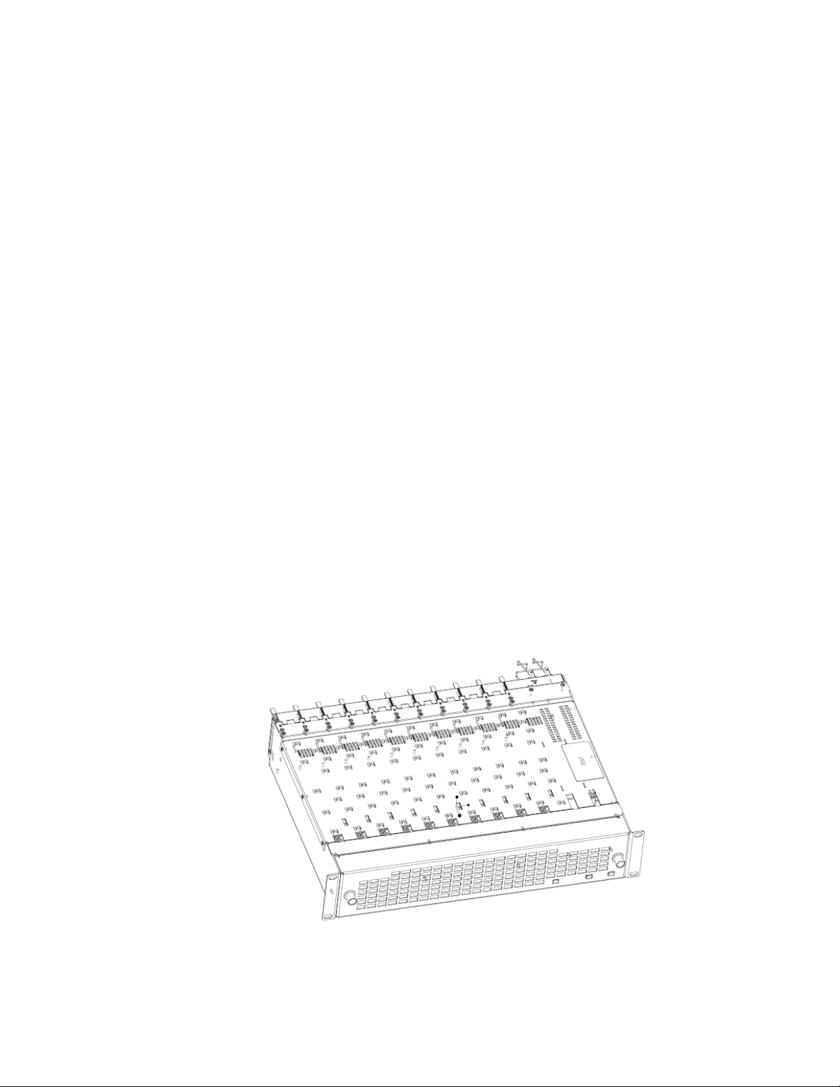
Module Placement in the GeckoFlex Frame
There are ten front and rear cell locations in the 2 RU GeckoFlex frame
Figure 1) to accommodate either audio, analog and digital video modules.
(
Figure 1. GeckoFlex Frame
8943CF — Instruction Manual 11
Page 12

Installation
Module Installation Precautions
Please read and follow the precautions listed below before installing the
front and rear modules and any optional fiber optic SFP devices:
• Use standard anti-static procedures during installation. As modules
can be installed or removed when the GeckoFlex frame is powered up,
before removing the cover, please use an anti-static bracelet tied to a
metal part of the frame.
• Install the rear module first, then install the fiber optic SFP device
option(s) on the front module, then install the front module.
• When installing or removing a rear module, loosen or tighten the
screws holding the retainer clips to the frame manually with the
retainer clip tool provided inside the front cover of the frame or use a
2 mm (5/64”) hex screwdriver. Please do not use an electric screwdriver.
Note On newer 751- version GeckoFlex frames, a Rear Retainer Clip removal tool
and 2 extra retainer clips and screws for installing them are provided on the
inside of the frame cover.
• Make every effort to leave the screws holding the retainer clips in place
(do not remove them completely). They are very small and can easily
drop into other equipment causing a shorting hazard. (Two turns of the
screw should be enough to loosen the screws, 3 turns or more will
remove it.)
• When installing a rear module, tighten the screws on the retainer clips
just until snug. Do not apply more force than is necessary to seat the
rear module. Refer to the
page 53.
• If using a fiber optic SFP device on the fiber-ready front module, handle
it carefully, use anti-static precautions, and read the Fiber Optic Cleaning
Requirement on page 14 before cabling.
Mechanical specifications given in Tab le 6 on
12 8943CF — Instruction Manual
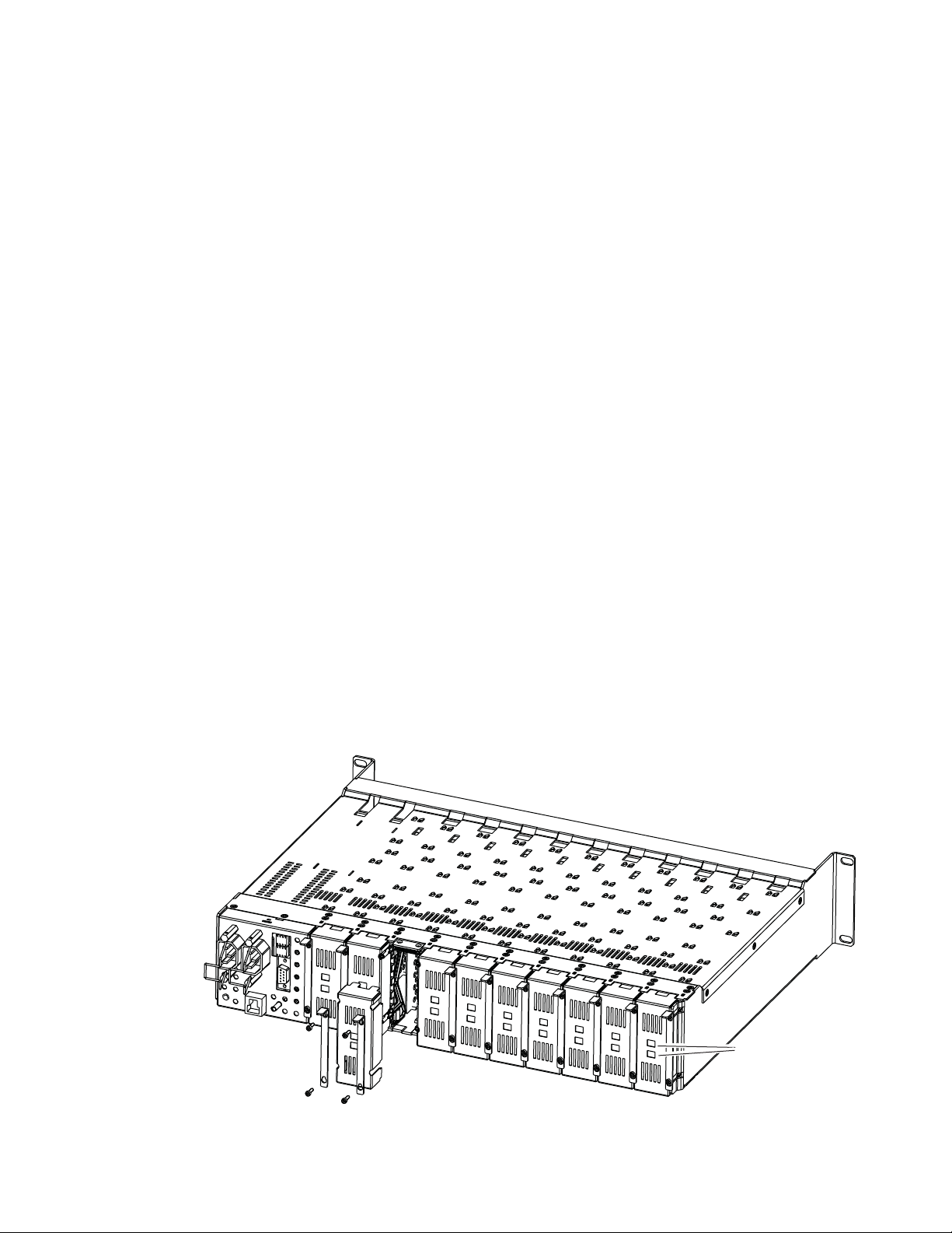
Page 13
Rear Module Installation
8771_07r0
Use retainer clip or
needlenose pliers
to pull out blank after
removing retainer clips
To install the rear module, refer to Figure 2 and the instructions below:
1. To remove a blank rear adapter cover (or a rear module already
present), manually loosen the two screws holding each retainer clip on
the rear adapter cover or rear module to the frame with the retainer clip
tool provided inside the front cover of the frame (newer model frames
only) or a 2 mm (5/64”) hex screwdriver. Do not remove the screws.
Note To remove a rear module already installed, follow the same steps. It is helpful
to first remove the front module so the rear can be pulled out more easily.
2. After loosening the retainer clip screws, pull up on each retainer and
completely remove it, leaving the screws in place.
3. Remove the blank rear adapter cover by inserting needlenose pliers
into the slots in the blank cover and pulling it off.
4. Insert the rear module into the empty slot, guiding it carefully.
Installation
5. Replace each retainer clip over the two screws on both sides of the
module and push down to seat the retainer clip.
6. Tighten the two screws on each retainer clip just until they come into
contract with the retainer clip then tighten about a 1/4 turn more
(maximum torque is 4-5 inch-lb/0.45-0.6Nm). Do not force or torque
the screws too tightly. The clips should not bend or be bowed.
Note All unused rear slots in a GeckoFlex frame should have a blank rear adapter
cover installed.
Figure 2. Installing Rear Module
8943CF — Instruction Manual 13
Page 14
Installation
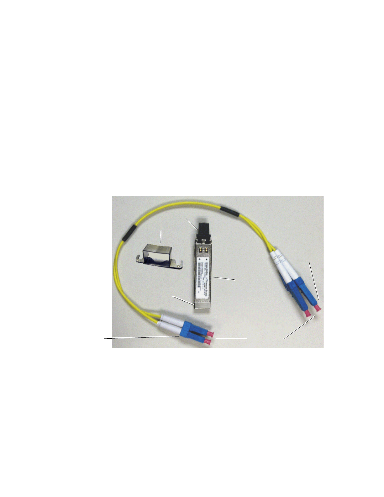
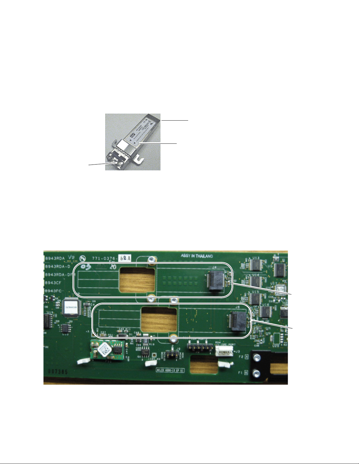
Ferrule covers
Duplex end connectors
Simplex end
Mounting Bracket
SFP device dust cover
SFP Device Label
SCA-2 Connector
connectors
Fiber Optic SFP Device Installation
Two optional dual channel CWDM transmitter SFP devices can be installed
on an 8943CF module. Both are installed on the front of the module circuit
board. The type of SFP device depends on the application of the module
and the 8939FCA or 8939FCB module it will be feeding. Refer to
page 10 for a list of available optional fiber optic SFP devices.
The optional strap-mount SFP Fiber Optic kit (Figure 3) for GeckoFlex
fiber-ready modules includes:
• One Strap Mount Fiber Optic SFP device (labeled for type) with dust
covers
• Mounting bracket for SFP device installation
• Fiber cable assembly (with dust covers) for connecting the SFP device
to front module LC adapter
Figure 3. SFP SFP Device Kit
Ta bl e 1 on
Fiber Optic Cleaning Requirement
Before making any fiber optic cable mating connections in the SFP device
or cabling and after every de-mating cycle, use an industry standard fiber
optic cleaning kit, including oil-free compressed air, to clean the fiber con
nectors and the connectorized fiber end faces. This helps ensure optimum
performance of the fiber optic interface. Industry standard fiber optic
cleaning kits can be purchased on the web and in electronics stores.
-
14 8943CF — Instruction Manual
Page 15
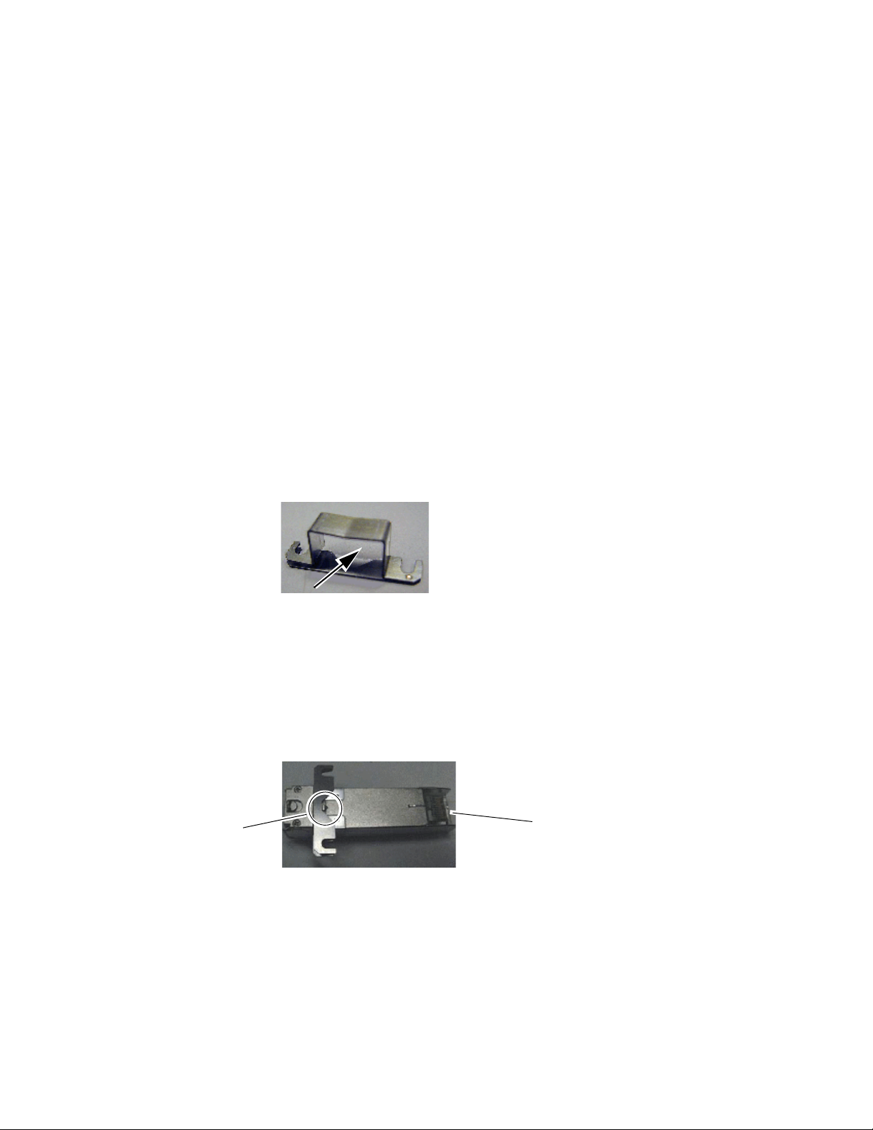
Installation
V-connection
SCA-2 (electrical) connector
Installation of each SFP device involves three steps:
1. Mount the metal bracket to the SFP device,
2. Mount the SFP device and bracket on the front of the 8943CF front
module, and
3. Install the fiber cable assembly to the SFP device and the rear fiber optic
LC adapter connectors.
CAUTION Use industry standard practice fiber optic cleaning and anti-static handling
procedures when installing and cabling the fiber optic devices or after any
de-mating cycle. Refer to Fiber Optic Cleaning Requirement on page 14.
Mount Metal Bracket to SFP Device
Attach the mounting bracket to the SFP device as shown below.
1. Insert the narrow end (SCA-2 connector) of the SFP device into the
mounting bracket, label side up with the open slots on the bracket
pointing to the rear as shown by the direction of the arrow in Figure 4.
Figure 4. Mounting Bracket
2. Attach the mounting bracket to the SFP device by sliding the bottom
part of the bracket as far as it will go (Figure 5) on the bottom side of the
SFP device to hold it in place without forcing it. Make sure the open
bracket slots point towards the SCA-2 (electrical) connector on the SFP
device.
Figure 5. Attach Bottom of Bracket to SFP Device
8943CF — Instruction Manual 15
Page 16
Installation
Fiber cable connectors
SCA-2 (electrical) connector
Arrows indicating SFP device type
J4 - F3/F4
J6 - F1/F2
3. The finished installation should look like the example in Figure 6. The
label will list the GV Model number, the GV part number, and the
manufacturer’s part number. Also note the two arrows on the label will
indicate signal direction as shown in the dual transmitter example in
Figure 6 (arrows pointing out). A dual receiver will have two arrows
pointing in, and a transceiver will have one input and one output
arrow.
Figure 6. Finished Bracket Mounting
Once you have put the mounting brackets onto the two SFP devices, install
them on the top (component) side of the circuit board and cable them to the
LC adapter output connectors on the main module with the fiber cable
assemblies provided.
Figure 7 shows an empty circuit board and the connector locations (J4 and
J6) where the SFP devices will be installed.
Figure 7. Example of a Complete SFP Installation
16 8943CF — Instruction Manual
Page 17
Installation
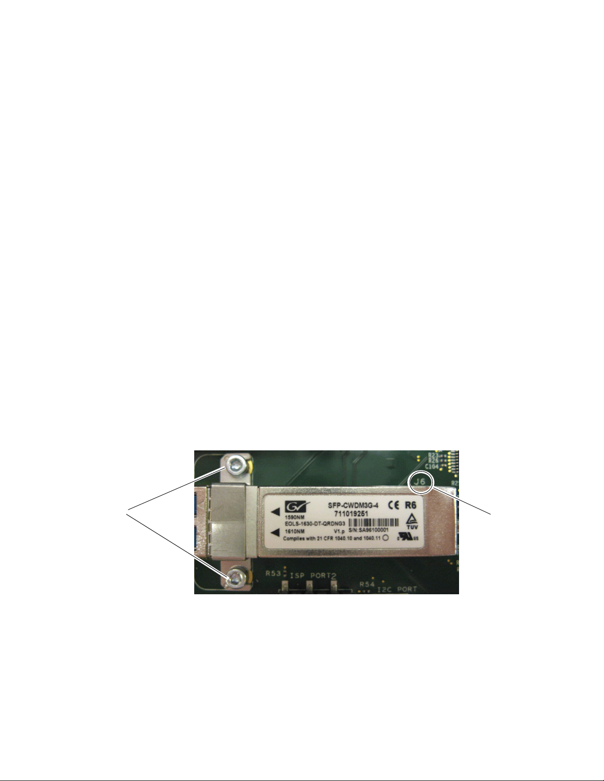
Slide bracket straps
under screws
and tighten.
SCA-2
connector, J6
Fiber Channel 1 and 2 SFP Device and Fiber Cable Installation
Note Before making any fiber connections, refer to the Fiber Optic Cleaning
Requirement on page 14.
After preparing the SFP devices for installation, install the transmitter SFP
device you wish to use for the Fiber Channel 1 and Fiber Channel 2 outputs
as follows:
Note This example uses a dual fiber transmitter with 1610nm (F1) and
1590nm (F2) as shown in Figure 8.
1. Remove the black rubber dust cover from the SFP device and clean the
fiber faces of both the SFP device and connector J6 as described in Fiber
Optic Cleaning Requirement on page 14.
2. Align the SFP device with the right angle bottom SCA-2 connector (J6)
and the mounting screws on the 8943CF module (Figure 8).
3. Loosen the two screws slightly (do not remove them completely) with
a torx screwdriver so the mounting bracket straps can slide under the
screws.
4. Slide the SFP device towards the SCA-2 connector so the electrical
connector on the SFP device engages with the SCA-2 connector until
the connector is completely covered and the straps are underneath the
two screws.
5. Tighten the screws to secure the SFP device to the front module.
Figure 8. Install F1 and F2 SFP Devices
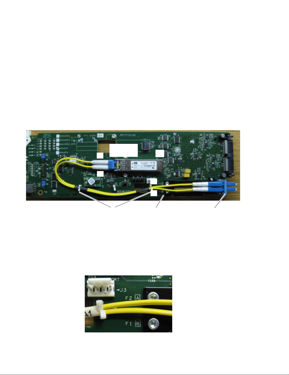
Now install the fiber cable assembly from the SFP device to the rear connector as described below.
1. Remove the dust covers from the fiber cable assembly connectors to
expose the LC ferrules (the ends of the fiber optic cable).
8943CF — Instruction Manual 17
Page 18
Installation
Simplex end of LC
Duplex end of
fiber cable
Plastic fiber guides
Fiber 1
Fiber 2
J6
F1 and F2 cable silkscreen guide
A
B
LC adapter ports
A
B
2. Clean the LC ferrules of the connectors (and after every de-mating
cycle) using an industry standard fiber optic cleaning kit as described
in Fiber Optic Cleaning Requirement on page 14. Also visually inspect the
LC ferrules for damage or blockage before connecting them.
3. Remove the rubber dust cover from the SFP device connector end.
Insert the duplex end of the fiber cable assembly (the two fiber optic
cables connected together) into the SFP device by holding the strain
relief boot directly behind the connector housing as shown in Figure 9.
Push on the strain relief until you hear a click, indicating the connectors
are properly mated.
4. Route the fiber cable assembly through the two plastic fiber guides as
shown in Figure 9 to hold it in place.
Figure 9. SFP Device Installation for F1 and F2
5. Insert the simplex ends of the fiber cable assembly (the two fiber optic
connectors that are separate) into the LC adapter ports at the rear of the
module. Fiber 1 (B) is the bottom cable from the SFP device (1610nm for
this example) and Fiber 2 (A) is the top cable (1590nm for this example).
Note the silkscreened F1 (B) and F2 (A) as shown in the detail in
Figure 10.
Figure 10. F1 and F2 Fiber Cable Silkscreen Guide Detail
18 8943CF — Instruction Manual
Page 19
Installation
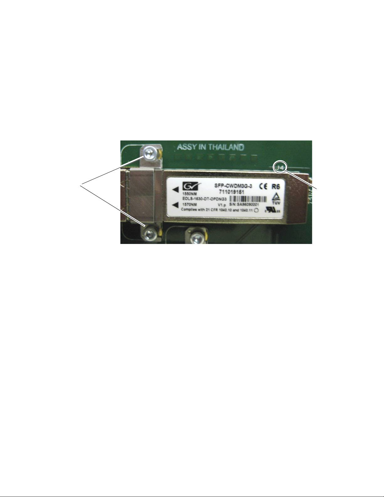
Slide bracket straps
under screws
and tighten.
SCA-2
connector, J4
Channel 3 and Channel 4 SFP Device and Fiber Cable Installation
Repeat the SFP device installation procedure for the second SFP device in
the top SCA-2 connector, J4, of the module. This SFP device will output
Fiber Channel 3 (1570nm) and Fiber Channel 4 (1550nm).
Follow the instructions for installing the SFP device in connector J4 in the
same manner as the instructions for J6 starting on
steps 1 through 5. The finished installation of the Fiber Channel 3 and Fiber
Channel 4 SFP device should resemble the one in
Figure 11. SFP Device Installation for Ch 3 and Ch 4
page 17,
Figure 11.
Now install the Fiber Channel 3 and 4 fiber cable assembly from the SFP
device to the rear LC adapter as described below.
1. Remove the dust covers from the fiber cable assembly connectors to
expose the LC ferrules (the ends of the fiber optic cable).
2. Clean the LC ferrules of the connectors (and after every de-mating
cycle) using an industry standard fiber optic cleaning kit as described
in Fiber Optic Cleaning Requirement on page 14. Also visually inspect the
LC ferrules for damage or blockage before connecting them.
3. Remove the rubber dust cover from the SFP device connector end.
Insert the duplex end of the fiber cable assembly (the two fiber optic
cables connected together) into the SFP device by holding the strain
relief boot directly behind the connector housing as shown in Figure 12
on page 20. Push on the strain relief until you hear a click, indicating the
connectors are properly mated.
8943CF — Instruction Manual 19
Page 20
Installation
Simplex end of LC jumper
Duplex end of
fiber cable
Plastic fiber guide
J4
Square hole in circuit board
B
A
A
4. Route the Fiber Channel 3 and 4 fiber cable assembly through the
remaining top side plastic fiber guide as shown in Figure 12 then insert
the simplex ends through the square opening below ISP connector, J2,
to the back side of the module.
Figure 12. SFP Device Installation for Fiber Ch 3 and Ch 4
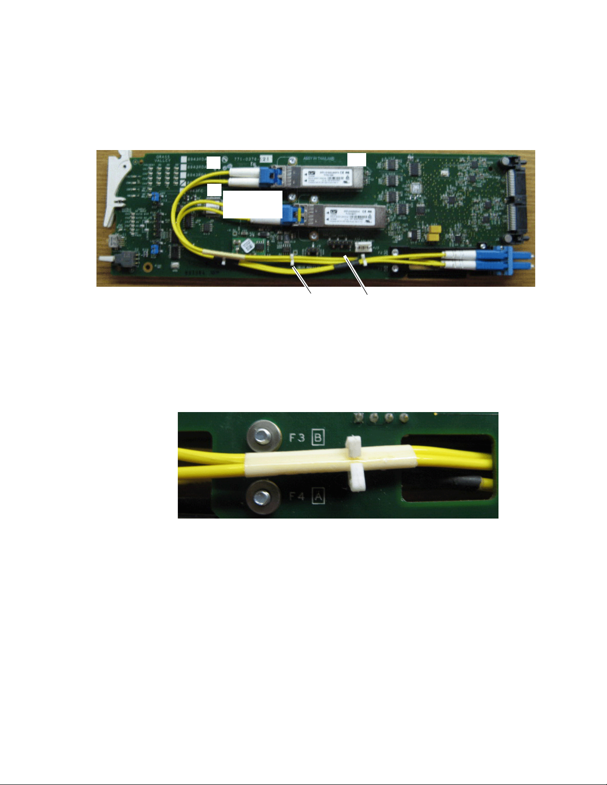
5. Put the fiber cable assembly through the cable guide on the back of the
circuit board to hold it in place (Figure 13).
Note the silkscreened F3 (B) and F4 (A) guides as shown in the detail in
Figure 13.
Figure 13. F3 and F4 Fiber Cable Silkscreen Guide Detail
20 8943CF — Instruction Manual
Page 21

Installation
Fiber 4
Fiber 3
Cable guide
B
A
6. Insert the simplex ends of the fiber cable assembly (the two fiber optic
connectors that are separate) into the LC adapter ports at the rear of the
module (shown in Figure 14). Fiber Channel 4 (A) (1550nm) is the top
cable from the SFP device and Fiber Channel 3 (B) (1570nm) is the
bottom cable.
Figure 14. F3 and F4 Fiber Cable Silkscreen Guide Detail
The fiber optic outputs from the rear module are shown in Figure 15.
Figure 15. Fiber Optic Outputs
2
1
OUTOUT
3
4
For the SFP device types and cabling examples used in this procedure, the
following frequencies should be output from this connector:
• Fiber Out 1 = 1610nm
• Fiber Out 2 = 1590nm
• Fiber Out 3 = 1570nm
• Fiber Out 4 = 1550nm
If you are using 8943CFs to multiplex 9 or 16 frequencies through the
8939FCA/FCB modules, the other 8943CFs should be equipped with the
SFP devices with the frequencies described in
CWDM Configuration on
page 25.
8943CF — Instruction Manual 21
Page 22

Installation
Slide top and bottom card carriers on module
over top and bottom guides on right of slot.
Module installed
Locking Pin
Front Module Side View
8771_09r0
Front Module Installation
After installing the rear module and SFP devices on the front module,
install the front module as follows:
1. Remove the front cover of the frame.
2. Locate the corresponding front slot.
3. Before installing the module, set the Local/Remote onboard jumper as
described in Local/Remote Jumper on page 37.
4. Clean the fiber optic connections as described in the Fiber Optic Cleaning
Requirement on page 14.
5. Insert the front module so that the module top and bottom edges go
through the upper and lower raised rail guides on the right of the top
and bottom of the slot (Figure 16).
6. Carefully slide the module into the rear connector.
7. Lock the front module ejector tab into the locking pin.
8. Replace the front cover for configuring the module using remote
controls.
Figure 16. Front Module Installation
22 8943CF — Instruction Manual
Page 23

Cabling
Installation
Cabling is done on the rear BNCs of the 8943CF-R module illustrated in
Figure 17.
Note Before making any fiber connections, refer to the Fiber Optic Cleaning
Requirement on page 14.
Figure 17. 8943CF-R Rear Module
CH 1 Electrical Out
CH 2 Electrical Out
CH 3 Electrical Out
CH 4 Electrical Out
CH 2 Fiber Out
CH 1 Fiber Out
OUT
OUT
OUT
2
1
8943CF-R
CH1
CH2
CH3
CH4
INOUT
CH 1 Electrical In
IN
CH 2 Electrical In
IN
CH 3 Electrical In
IN
CH 4 Electrical In
3
4
OUTOUT
CH 3 Fiber Out
CH 4 Fiber Out
8772_01r0
Attenuation Requirements
Some shorter length cable runs will require attenuation to prevent overdriving the receiver causing bit errors to occur on the fiber link. Use the following guidelines for adding attenuation:
• The 1310nm Dual Transmitter (SFP-13103G-M1DTX) requires no attenuation between fiber transmitter and receiver connections at any cable
lengths.
• CWDM devices used with 8939FCA modules for a mux/demux configuration (page 25) with a cable run from 0-12 km (7.5 miles), must be
attenuated by 3 dB between 8939FCA COM ports.
• All CWDM devices used in a point-to-point configuration with a cable
run from 0-20 km (12.4 miles), must be attenuated by 5 dB between
fiber transmitter and receiver connections.
8943CF — Instruction Manual 23
Page 24

Installation
Electrical Inputs
Connect a signal conforming to the to the specifications given in Tab le 6 on
page 53 to the coax inputs for Channel 1 -4 as labeled on the rear of the
8943CF-R module.
Electrical Outputs
There are four electrical coax video outputs corresponding to Channel 1-4
as labeled on the rear of the 8943CF-R module.
Fiber Optic Outputs
There are four fiber optic output ports corresponding to Channel 1-4 as
labeled on the rear of the 8943CF-R module (
Note Before making any fiber connections, refer to the Fiber Optic Cleaning
Requirement on page 14.
For the fiber output ports, the 8943CF-R rear module shall follow the
channel allocation convention shown in
channel 3 are mapped to the B side of standard duplex fiber connector and
channel 2 and channel 4 are mapped to the A side of a standard duplex fiber
connector.
Figure 17 on page 23).
Figure 18. Optical channel 1 and
Figure 18. 8943CF to 8943CF Fiber Transmit Channels
8943CF to 8943FC Connections
When connecting an 8943CF module directly to an 8943FC (point-to-point),
a non-crossing duplex fiber cable is required shown in
Attenuation Requirements on page 23 for cable length attenuation notes.
Non-crossing is in reference to the logical A/B nomenclature associated
with the duplex connector illustrated below. Side 1A connects to side
and side 1B connects to side 2B. Refer to
Figure 19. Non-Crossing Duplex Fiber Cable
Figure 19.
Figure 19. Refer to
2A
24 8943CF — Instruction Manual
Page 25

CWDM Configuration
8943CF
Coax 1-4 In
Fiber 1-4 Out
8943CF
Coax 5-8 In
Coax In
Fiber 1-4 Out
Fiber Out
8943FC
Fiber 1-4 In
Coax 1-4 Out
8943FC
Fiber 1-4 In
Fiber In
Coax 5-8 Out
Coax Out
8939FCA 8939FCA
GeckoFlex module
with 1310nm SFP
GeckoFlex module
with 1310nm SFP
8771_04r1
The 8943CF module can be used for CWDM (Coarse Wavelength Division
Multiplexing) in various configurations in conjunction with 8939FCA/
8939FCB modules and 8943FC modules as well as other fiber-ready
modules from Grass Valley. Two main examples are given in this manual.
CWDM Configuration for 9 Channels
One use of CWDM involves the ability to multiplex and demultiplex up to
9 channels of video in as shown in the simple block diagram in
Figure 20. Simple CWDM Block Diagram
Installation
Figure 20.
When an 8943CF module is populated with CWDM SFP devices, a standard crossing duplex cable is required when connecting the 8943CF
modules to the 8939FCA modules.
Crossing is in reference to the logical A/B nomenclature associated with
the duplex connector illustrated in
side 2B and side 1B connects to side 2A.
Figure 21. Standard Crossing Duplex Fiber Cable
Figure 21 where side 1A connects to
8943CF — Instruction Manual 25
Page 26

Installation
To utilize this nine channel Mux/Demux application, the following Grass
Valley modules are needed:
• Two 8943CF 4 Channel Electrical to Fiber Converter modules with one
of each type of CWDM SFP device
• Two 8943FC 4 Channel Fiber to Electrical Converter modules with one
of each type of CWDM SFP device
• Two fiber-ready Grass Valley GeckoFlex modules with 1310nm SFP
devices
As shown in the detailed block diagram in Figure 22 on page 27, two
8943CF (Electrical to Fiber converters) at Location A are used to feed 8
channels of video to an 8939FCA. To utilize this application, one of each of
the following four CWDM SFP device types must be installed on the two
8943CF modules:
• SFP-CWDM3G-1-K Dual Transmitter (1490nm/1470nm frequencies)
• SFP-CWDM3G-2-K Dual Transmitter (1510nm/1530nm frequencies)
• SFP-CWDM3G-3-K Dual Transmitter (1550nm/1570nm frequencies)
• SFP-CWDM3G-4-K Dual Transmitter (1590nm/1610nm frequencies)
Note The four SFP devices can be installed in any location on the two 8943CF
modules as long as the outputs are cabled to the correct frequency input on
the 8939FCA. The installation configuration shown here is for clarity only.
The 1310nm fiber output from a Grass Valley GeckoFlex module is cabled
to the EXP (Expansion) port on the 8939FCA.
The 8939FCA module multiplexes these 9 frequencies down to a single
output from the COM port. A single fiber cable carries these 9 video fiber
channels to the COM port of the 8939FCA at Location B.
The 8939FCA at Location B acts as a demultiplexer and outputs 9 fiber
video channels to two 8943FC (fiber to electrical) modules, each with two
SFP-13103G-M1DRX-K Dual Receiver SFP devices installed and a Grass
Valley fiber-ready module. This SFP device will accept input frequencies
from 1270nm to 1610nm.
Refer to Attenuation Requirements on page 23 concerning the attenuation
needed depending on the length of cable run between 8939FCA COM
ports.
26 8943CF — Instruction Manual
Page 27

8772_04r1
8939FCA
8943CF
Fiber Out 1
to 1610nm
Fiber In 1
from 1610nm
Fiber In 2
from 1590nm
Fiber In 3
from 1570nm
Fiber In 4
from 1550nm
Fiber Out 3
to 1570nm
Fiber Out 4
to 1550nm
Fiber Out 2
to 1590nm
Fiber Out 1
to 1530nm
Fiber Out 3
to 1490nm
Fiber Out 4
to 1470nm
Fiber Out 2
to 1510nm
Electrical
Inputs
Multiplexer
Demultiplexer
Connector J6
Connector J4
8943CF
SFP-CWDM3G-3-K
1550nm & 1570nm
Fiber In 1
from 1530nm
Fiber In 2
from 1510nm
Fiber In 3
from 1490nm
Fiber In 4
from 1470nm
Connector J6
SFP-CWDM3G-4-K
1590nm & 1610nm
Connector J4
SFP-CWDM3G-1-K
1470nm & 1490nm
SFP-CWDM3G-2-K
1510nm & 1530nm
8943FC
Connector J4
Connector J6
Connector J4
SFP-13103G-M1DRX-K
1270 > 1610nm
SFP-13103G-M1DRX-K
1270 > 1610nm
SFP-13103G-M1DRX-K
1270 > 1610nm
SFP-13103G-M1DRX-K
1270 > 1610nm
Connector J6
COM EXP
CH1
1470nm
CH2
1490nm
CH4
1530nm
CH3
1510nm
CH4
1570nm
CH5
1550nm
CH8
1610nm
CH7
1590nm
8939FCA
COM EXP
CH1
1470nm
CH2
1490nm
CH4
1530nm
CH3
1510nm
CH4
1570nm
CH5
1550nm
CH8
1610nm
CH7
1590nm
8943FC
Electrical
Outputs
Location A Location B
8935FC Fiber Inputs
1
2
4
3
IN IN
8935CF Fiber Outputs
1
2
4
3
OUT OUT
GeckoFlex Fiber-Ready Module
SFP-13103G-M1DTX
GeckoFlex Fiber-Ready Module
1310-DRL
Submodule
Ch 1
Ch 2
Ch 3
Ch 4
Ch 1
Ch 2
Ch 3
Ch 4
Coax In
Fiber Out
Ch 1
Coax
Ouputs
Ch 3
Ch 4
Ch 2
Ch 1
Ch 2
Ch 3
Ch 4
Ch 1
Ch 3
Ch 4
Ch 2
Ch 1
Ch 2
Ch 3
Ch 4
Note: In this configuration (8959FCA to 8939FCA utilizing CWDM transmitters), if the distance between 8939FCA modules is less than 12 km (7.5 m),
a 3 dB attenuator must be installed somewhere between the COM ports on the 8939FCA modules to prevent overdriving the receiver causing bit errors
to occur on the link.
Distance of
up to 50km
( see note
for inline
attenuation
requirements)
*
Single-mode fiber cable
Installation
Figure 22. 8939FCA CWDM Configuration
8943CF — Instruction Manual 27
Page 28

Installation
CWDM 16 Channel Configuration
The 8943CF and 8943FC can also be used with the 8939FCA and the
8939FCB to provide 16 channels of video over a single fiber connection.
As shown in the simple block diagram in Figure 23, the two 8939FCB
module COM ports can be connected to the 8939FCA module EXP ports to
provide another eight channels of video, for a total of 16 channels over one
fiber.
The 8939FCB must be set up in a similar manner as the 8939FCA
(CH1 – CH8) only using a different set of CWDM fiber optic SFP devices
with frequencies pairs from 1310nm to 1450nm (CH9 – CH16).
Figure 23. 8939FCA and 8939FCB Simple Block Diagram
8943CF
(1450nm) Ch16 TX
(1430nm) Ch15 TX
(1410nm) Ch14 TX
(1390nm) Ch13 TX
8943CF
(1370nm) Ch12 TX
(1350nm) Ch11 TX
(1330nm) Ch10 TX
(1310nm) Ch9 TX
8939FCB
MUX
COM
8939FCB
EXP (N/A)(N/A) EXP
DEMUX
COM
8943FC
Ch16 RX (1270 to 1610nm)
Ch15 RX (1270 to 1610nm)
Ch14 RX (1270 to 1610nm)
Ch13 RX (1270 to 1610nm)
8943FC
Ch12 RX (1270 to 1610nm)
Ch11 RX (1270 to 1610nm)
Ch10 RX (1270 to 1610nm)
Ch9 RX (1270 to 1610nm)
8943CF
(1610nm) Ch8 TX
(1590nm) Ch7 TX
(1570nm) Ch6 TX
(1550nm) Ch5 TX
8943CF
(1530nm) Ch4 TX
(1510nm) Ch3 TX
(1490nm) Ch2 TX
(1470nm) Ch1 TX
8939FCA
EXP
MUX
COM
Single-mode Fiber (up to 50 km)
EXP
COM
8939FCA
DEMUX
8943FC
Ch8 RX (1270 to 1610nm)
Ch7 RX (1270 to 1610nm)
Ch6 RX (1270 to 1610nm)
Ch5 RX (1270 to 1610nm)
8943FC
Ch4 RX (1270 to 1610nm)
Ch3 RX (1270 to 1610nm)
Ch2 RX (1270 to 1610nm)
Ch1 RX (1270 to 1610nm)
8543_13r0
28 8943CF — Instruction Manual
Page 29

Installation
To utilize a 16 channel configuration using the 8939FCA and 8939FCB modules, follow the setup below.
Install the CWDM fiber optic SFP devices on the 8943CF as described in
CWDM Configuration on page 25. You will be using the EXP ports to connect
to the 8939FCB instead of a 1310nm GeckoFlex fiber-ready module.
The 8943CF modules feeding the 8939FCA should have the following fiber
optic SFP devices installed for channels 1-8:
• SFP-CWDM3G-1-K Dual Transmitter (1490nm/1470nm frequencies)
• SFP-CWDM3G-2-K Dual Transmitter (1510nm/1530nm frequencies)
• SFP-CWDM3G-3-K Dual Transmitter (1550nm/1570nm frequencies)
• SFP-CWDM3G-4-K Dual Transmitter (1590nm/1610nm frequencies)
The eight additional channels are provided by two 8943CF modules
feeding the 8939FCB with the following CWDM transmitter SFP devices:
• SFP-CWDM3G-5-K Dual Transmitter (1310nm/1330nm frequencies)
• SFP-CWDM3G-6-K Dual Transmitter (1350nm/1370nm frequencies)
• SFP-CWDM3G-7-K Dual Transmitter (1390nm/1410nm frequencies)
• SFP-CWDM3G-8-K Dual Transmitter (1430nm/1450nm frequencies)
The 8943FC modules receiving the fiber from the 8939FCA and the
8939FCB should have SFP-13103G-M1DRX-K Dual Receivers installed in
all SFP locations. Refer to the detailed diagram in
Figure 24 on page 30.
8943CF — Instruction Manual 29
Page 30

Installation
8772_05r1
8939FCA
8943CF
Fiber Out 1
to 1450nm
Fiber In 1
from 1450nm
Fiber In 2
from 1430nm
Fiber In 3
from 1410nm
Fiber In 4
from 1390nm
Fiber Out 3
to 1410nm
Fiber Out 4
to 1390nm
Fiber Out 2
to 1430nm
Fiber Out 1
to 1370nm
Fiber Out 3
to 1330nm
Fiber Out 4
to 1310nm
Fiber Out 2
to 1350nm
Electrical
Inputs
To 8939FCA
DEMUX COM port
To 8939FCA
MUX COM port
Multiplexer
Demultiplexer
Connector J6
Connector J4
8943CF
SFP-CWDM3G-7-K
1390nm & 1410nm
Fiber In 1
from 1370nm
Fiber In 2
from 1350nm
Fiber In 3
from 1330nm
Fiber In 4
from 1310nm
Connector J6
SFP-CWDM3G-8-K
1430nm & 1450nm
Connector J4
SFP-CWDM3G-5-K
1310nm & 1330nm
SFP-CWDM3G-6-K
1350nm & 1370nm
8943FC
Connector J6
Connector J4
Connector J6
SFP-1310-M1DRX-K
1270 > 1610nm
SFP-1310-M1DRX-K
1270 > 1610nm
SFP-1310-M1DRX-K
1270 > 1610nm
SFP-1310-M1DRX-K
1270 > 1610nm
Connector J4
COM EXP
CH9
1310nm
CH10
1330nm
CH12
1370nm
CH11
1350nm
CH14
1410nm
CH13
1390nm
CH16
1450nm
CH15
1430nm
8939FCA
COM EXP
CH9
1310nm
CH10
1330nm
CH12
1370nm
CH11
1350nm
CH14
1410nm
CH13
1390nm
CH16
1450nm
CH15
1430nm
8943FC
Electrical
Outputs
Location A Location B
8943FC Fiber Inputs
1
2
4
3
IN IN
8943CF Fiber Outputs
1
2
4
3
OUT OUT
Ch 1
Ch 2
Ch 3
Ch 4
Ch 1
Ch 2
Ch 3
Ch 4
Ch 1
Ch 3
Ch 4
Ch 2
Ch 1
Ch 2
Ch 3
Ch 4
Ch 1
Ch 3
Ch 4
Ch 2
Ch 1
Ch 2
Ch 3
Ch 4
Note: In any configuration utilizing CWDM transmitters, if the distance between 8939FCA modules is less than 12 km (7.5 m),
a 3 dB attenuator must be installed somewhere between the COM ports on the 8939CFA modules to prevent overdriving the receiver causing bit errors
to occur on the link.
*
Single-mode fiber cable
*
Distance of
up to 50km
Figure 24. 8939FCB Configuration
30 8943CF — Instruction Manual
Page 31

Configuration and Monitoring
8943CF module configuration and monitoring can be performed locally
using the onboard controls or using a web browser GUI interface or the
Newton Control Panel when the 8900NET Network Interface module is
present in the GeckoFlex frame. Control and monitoring is described in the
following sections:
• Operating Modes Overview – page 31
• Local Configuration and Monitoring – page 34
• Remote Configuration and Monitoring – page 39
Input Operating Modes Overview
Each of the four channels must be configured for the desired input mode.
This can be done using the on-board switches, on the Settings web page
using the web browser interface, or with the Newton Control Panel. The
different modes of operation are described in this section. Input signal
monitoring differs between modes as described in each mode section
below. For an input signal monitoring summary, refer to
Configuration and Monitoring
Tab le 3 on page 36.
The 8943CF supports the following modes of operation:
• Auto Reclock/Bypass mode
• Auto Reclock/Mute mode
• 3G 2970M mode
• HD 1485M mode
• SD 270M mode
•Manual Bypass HD/3G
•Manual Bypass SD
Auto Reclock/Bypass Mode
In this mode, the electrical inputs are equalized and fed to the reclocker. If
the specific bit rates of 270Mb/s, 1485Mb/s, or 2970Mb/s are analyzed by
the module, it will reclock the signal at the determined bit rate and feed this
signal to both the electrical BNC and the fiber optic outputs. With input
reporting enabled, the input signal will be reported as
If a bit rate other than 270Mb/s, 1485Mb/s, or 2970Mb/s is detected by the
module or no input signal is detected, reclocking will not be performed and
the signal will be automatically bypassed to the outputs. With input
reporting enabled, the input signal will be reported as
Present.
Not Monitored.
8943CF — Instruction Manual 31
Page 32

Configuration and Monitoring
Auto Reclock/Mute Mode (Default)
In this mode, the electrical inputs are equalized and fed to the reclocker. If
the specific bit rates of 270Mb/s, 1485Mb/s, or 2970Mb/s are analyzed by
the module, it will reclock the signal at the determined bit rate and feed this
signal to both the electrical BNC and the fiber optic outputs. With input
reporting enabled, the input signal will be reported as
If the input signal is not 270Mb/s, 1485Mb/s, or 2970Mb/s, or the signal
input is not present, the output of the reclocker will be muted and the
outputs will be static (muted). With input reporting enabled, the input
signal will be reported as
3G 2970M Mode
In this mode, the electrical inputs are equalized and fed to the reclocker. If
the bit rate is analyzed as 2970Mb/s (3G), the module will reclock the signal
at the determined bit rate and feed this signal to both the electrical BNC and
the fiber optic outputs. With input reporting enabled, the input signal will
be reported as
Present.
Not Present.
Present.
If no input signal or a signal other than 2970Mb/s (3G) is detected by the
module, the output of the reclocker will be muted and the outputs will be
static (muted). With input reporting enabled, the signal input will be
reported as
HD 1485M Mode
In this mode, the electrical inputs are equalized and fed to the reclocker. If
the bit rate is analyzed as 1485Mb/s (HD), the module will reclock the
signal at the determined bit rate and feed this signal to both the electrical
BNC and the fiber optic outputs. With input reporting enabled, the input
signal will be reported as
If no input signal or a signal other than 1485Mb/s is detected by the
module, the output of the reclocker will be muted and the outputs will be
static (muted). With input reporting enabled, the signal input will be
reported as
Not Present.
Not Present.
Present.
32 8943CF — Instruction Manual
Page 33

SD 270M Mode
In this mode, the electrical inputs are equalized and fed to the reclocker. If
the bit rate is analyzed as 270Mb/s (SD), the module will reclock the signal
at the determined bit rate and feed this signal to both the electrical BNC and
the fiber optic outputs. With input reporting enabled, the input signal will
be reported as
If no input signal or a signal other than 270Mb/s is detected by the module,
the output of the reclocker will be muted and the outputs will be static
(muted). With input reporting enabled, the signal input will be reported as
Not Present.
Present.
Manual Bypass HD/3G Mode
In this mode, the electrical inputs are equalized and fed to the reclocker.
The bit rate is analyzed by the module. If the bit rate is analyzed as
1485Mb/s or 2970Mb/s, the module will reclock the signal at the deter
mined bit rate and feed this signal to the both the electrical BNC and the
fiber optic outputs. With input reporting enabled, the input signal will be
reported as
Present.
Configuration and Monitoring
-
If a bit rate other than 1485Mb/s or 2970Mb/s is detected by the module or
no input signal is detected, reclocking will not be performed and the signal
will be automatically bypassed to the outputs. With input reporting
enabled, the input signal will be reported as
Manual Bypass SD Mode
In this mode, the electrical inputs are equalized and fed to the reclocker.
The bit rate is analyzed by the module. If the bit rate is analyzed as
270Mb/s, the module will reclock the signal at the determined bit rate and
feed this signal to the both the electrical BNC and the fiber optic outputs.
With input reporting enabled, the input signal will be reported as
If a bit rate other than 270Mb/s is detected by the module or no input signal
is detected, reclocking will not be performed and the signal will be auto
matically bypassed to the outputs. With input reporting enabled, the input
signal will be reported as
Not Monitored.
Present.
-
Not Monitored.
8943CF — Instruction Manual 33
Page 34

Configuration and Monitoring
Module Status LEDs
Signal Status LEDs
Fiber Optic Option
Present LEDs
Local Monitoring and Configuration
The 8943CF module can be configured and monitored locally using
on-board rotary and paddle switches and the status and configuration
LEDs mounted on the top of the module circuit board. If an 8900NET (Net
Card) module is present for providing remote monitoring, refer to
Monitoring and Controls on page 39.
Local On-board Status Monitoring LEDs
As shown in Figure 25, there are three sets of on-board status LEDs on the
top of the circuit board for local monitoring:
• Module status for FAULT, POWER, COMM, and CONF.
• Signal PRESENT and RATE DETECTED (3G, HD, or SD).
• Fiber optic SFP device PRESENT.
Refer to Tab le 2 on page 35 for an description of each LED color and function.
Remote
Figure 25. On-board Status LED Monitoring
34 8943CF — Instruction Manual
Page 35

Table 2. On-board Module Status LED Names and Conditions
LED Indication Condition
Module Status LEDs
FAULT
(red)
COMM
(yellow)
CONFIG
(yellow)
PWR
(green)
CH1-4
PRESENT
(green)
CH1-4
3G
(blue)
CH1-4
HD
(green)
CH1-4
SD
(yellow)
OPT MOD_1
OPT MOD_2
Off Normal operation, module OK.
On continuously Module has detected an internal fault.
Flashing Configuration problems. Check inputs and settings. Missing video input.
Off No activity on frame communication bus.
Flashing Locate Module command received by the module from a remote control system.
Pulse
(short duration
Off Module is in normal operating mode, no configuration change in progress or initialization complete.
On continuously Module is initiating or changing operating modes.
Flashing Locate Module command received by the module from a remote control system.
Off No power to module or module’s DC/DC converter failed.
On continuously Normal operation, module is powered.
Off No signal is present.
On continuously Input signal is either, 270Mb/s, 1485Mb/s, or 2970Mb/s.
Off Input signal is not 2970Mb/s.
On continuously Input signal is 2970Mb/s.
Off Input signal is not 1485Mb/s.
On continuously Input signal is 1485Mb/s.
Off Input signal is not 270Mb/s.
On continuously Input signal is 270Mb/s.
Off No fiber option transmitter SFP device is installed in position J6.
On continuously Fiber optic option transmitter SFP device is installed in position J6.
Off No fiber option transmitter SFP device is installed in position J4.
On continuously Fiber optic option transmitter SFP device is installed in position J4.
Activity present on the frame communication bus.
Input Signal Status LEDs
SFP Device OPTION PRESENT LEDs
Configuration and Monitoring
Ta bl e 3 on page 36 outlines the conditions that will result in the reported
state of the input being Present or Not Present with the onboard LEDs and the
conditions of the output based on the operating mode, the Input Presence,
the actual input standard, and the Input Reporting State
8943CF — Instruction Manual 35
Page 36

Configuration and Monitoring
Table 3. Reported Input/Output Status Summary
Operating
Mode
Auto Reclock/Bypass Not Present N/A Off Off Off Off N/A
Auto Reclock/Bypass Present N/A Green Off Off Off Input Signal
Auto Reclock/Bypass Present
Auto Reclock/Bypass Present 270Mb/s Green Off Off Yellow
Auto Reclock/Bypass Present 1485Mb/s Green Off Green Off
Auto Reclock/Bypass Present 2970Mb/s Green Blue Off Off
Auto Reclock/Mute Not Present N/A Off Off Off Off Muted
Auto Reclock/Mute Present
Auto Reclock/Mute Present 270Mb/s Green Off Off Yellow
Auto Reclock/Mute Present 1485Mb/s Green Off Green Off
Auto Reclock/Mute Present 2970Mb/s Green Blue Off Off
Fixed 270M/Mute Not Present N/A Off Off Off Off Muted
Fixed 270M/Mute Present Not 270Mb/s Off Off Off Off Muted
Fixed 270M/Mute Present 270Mb/s Green Off Off Yellow
Fixed 1485M/Mute Not Present N/A Off Off Off Off Muted
Fixed 1485M/Mute Present Not 1485Mb/s Off Off Off Off Muted
Fixed 1485M/Mute Present 1485Mb/s Green Off Green Off
Fixed 2970M/Mute Not Present N/A Off Off Off Off Muted
Fixed 2970M/Mute Present Not 2970Mb/s Off Off Off Off Muted
Fixed 2970M/Mute Present 2970Mb/s Green Blue Off Off
1
When a signal is missing on any input, the red FAULT LED will flash on the front of the module circuit board.
Input
Carrier
Detect
1
Reclocker
Locked
Not 270M,
1485Mb/s, or
2970Mb/s
Not 270M,
1485Mb/s, or
2970Mb/s
PRES
LED
Green Off Off Off Input Signal
Off Off Off Off Muted
3G
LED
HD
LED
SD
LED
1485Mb/s
2970Mb/s
1485Mb/s
2970Mb/s
1485Mb/s
2970Mb/s
Output Reporting
Disabled Not Monitored
Enabled Not Monitored
Disabled Not Monitored
Enabled Present
Disabled Not Monitored
Enabled Present
Reclocked
270Mb/s
Reclocked
Reclocked
Reclocked
270Mb/s
Reclocked
Reclocked
Reclocked
270Mb/s
Reclocked
Reclocked
Disabled Not Monitored
Enabled Present
Disabled Not Monitored
Enabled Present
Disabled Not Monitored
Enabled Present
Disabled Not Monitored
Enabled Not Present
Disabled Not Monitored
Enabled Not Present
Disabled Not Monitored
Enabled Present
Disabled Not Monitored
Enabled Present
Disabled Not Monitored
Enabled Present
Disabled Not Monitored
Enabled Not Present
Disabled Not Monitored
Enabled Not Present
Disabled Not Monitored
Enabled Present
Disabled Not Monitored
Enabled Not Present
Disabled Not Monitored
Enabled Not Present
Disabled Not Monitored
Enabled Present
Disabled Not Monitored
Enabled Not Present
Disabled Not Monitored
Enabled Not Present
Disabled Not Monitored
Enabled Present
Reported
Input State
36 8943CF — Instruction Manual
Page 37

Local Mode Configuration
Rotary Switch, S1
Paddle Switch, S2
Local/Remote Jumper
Input Op Mode
Configuration LEDs
CONF LED
TX OPT Jumper
The module may be configured using the local on-board rotary switch and
paddle switch in conjunction with the configuration LEDs shown in
Figure 26. If an 8900NET (Net Card) module is present for providing
remote configuration, refer to Remote Monitoring and Controls on page 39.
Local/Remote Jumper
The on-board jumper Local/Remote jumper, J10, (Figure 26) is set at the
factory for local and remote (LOC/REM position, pins 2-3) to allow remote
control. It can be changed to lock out remote control if desired (LOC posi
tion, pins 1-2).
TX OPT Jumper
The on-board TX OPT jumper J13, (Figure 26) enables or disables the fiber
optic transmitter outputs when the optional fiber optic transmitter SFP
devices are installed. Set jumper J13 to pins 1-2 to enable the fiber outputs
and pins 2-3 to disable. When disabled, there will be a warning on the Set
tings web page (page 49) that the outputs are disabled with jumper J13.
Configuration and Monitoring
-
-
Figure 26. On-board Configuration Switches and LEDs
8943CF — Instruction Manual 37
Page 38

Configuration and Monitoring
The local configuration controls are described below and shown in
Figure 26 on page 37. Refer to Tab le 4 for the switch settings to set each
parameter.
• Function (rotary) switch (S2) – this switch is used to access each of the
• Paddle switch (S1) – scrolls through the available modes for the selected
• CONFIG (configuring) LED – when on, indicates the module is initial-
Table 4. Mode Configuration Functions
four channels for configuration. The switch has 16 possible positions (0
through 9 and A through F). Only positions 1, 2, 3, 4, and F are used (see
Tab le 4 ). Bank 2 is also not used in this application.
channel when the switch is held momentarily in either the up or down
position.
izing or processing configuration information.
Function
Switch
Setting
0 – – Park position for normal operation (paddle switch has no effect)
1
2 Scroll to Channel 2 input operating mode
3 Scroll to Channel 3 input operating mode
4 Scroll to Channel 4 input operating mode
5-9 – –
A-E – –
F Recall
Paddle
Switch Up
Switch Down
Auto By,
Auto RC,
3G,
HD,
SD,
or By.
Paddle
Function Description
Scroll to Channel 1 input operating mode
Not used
Recall factory defaults (all channels have Reporting Enabled and
Auto/Mute mode selected).
Note When configuration is complete, the Function switch should be parked in an
unused position such as 0 during normal operation to avoid changing the
mode accidently with the paddle switch.
38 8943CF — Instruction Manual
Page 39

Remote Monitoring and Controls
The 8943CF module can be configured and monitored when an 8900NET
module is installed in the GeckoFlex frame using the web-based GUI or a
networked Newton Control Panel.
8900NET Module Information
Refer to the 8900NET Network Interface Module Instruction Manual for information on the 8900NET Network Interface module and setting up and
operating the GeckoFlex frame network.
Note The 8900NET module in the GeckoFlex frame is recommended to be running
software version 4.3.0 or higher for proper remote and control panel operation. Upgrade software and instructions for the 8900NET can be downloaded
from the Grass Valley web site at this location:
ftp://ftp.grassvalley.com/modular/8900/8900net/v4.3.0/
Configuration and Monitoring
Newton Control Panel Configuration
A Newton Control Panel (hard and/or soft version) can be interfaced to the
GeckoFlex frame over the local network when the 8900NET (Net Card) is
present. Refer to the documentation that accompanies the Newton
Modular Control System for installation, configuration, and operation.
Control panel access offers the following considerations for module configuration and monitoring:
• Ability to separate system level tasks from operation ones, minimizing
the potential for on-air mistakes.
• Ability to group modular products—regardless of their physical locations—into logical groups (channels) that you can easily manipulate
with user-configured knobs.
• Update software for applicable modules and assign frame and panel IP
addresses with the NetConfig Networking application.
• Recommended for real-time control of module configuration parameters, providing the fastest response time.
Note Not all module functions may be available with the control panel.
8943CF — Instruction Manual 39
Page 40

Configuration and Monitoring
An example of the Newton Configurator is shown in Figure 27. Newton
Control Panel parameters are listed in Tab le 8 on page 61.
Figure 27. Newton Configurator Example
Web Browser Interface
The web browser interface provides a graphical representation of module
configuration and monitoring.
Use of the web interface offers the following considerations (when applicable for the module):
• Provides complete access to all module status and configuration functions, including factory parameter default recalls, slot configuration,
and SNMP monitoring controls.
• Web access will require some normal network time delays for processing of information.
• Configuration parameter changes may require pressing
Enter, upload processing time, and a manual screen refresh to become
effective.
• Web interface recommended for setting up module and reporting
status for SNMP and monitoring.
Refer to the Frame Status page shown in Figure 28 on page 41. The modules
can be addressed by clicking either on a specific module icon in the frame
status display or on a module name or slot number in the link list on the
left.
Apply button or
40 8943CF — Instruction Manual
Page 41

Configuration and Monitoring
8772_06r0
The Links section lists the frame and its current modules. The selected link's Status
page is first displayed and the sub-list of links for the selection is opened. The sub-list
allows you to select a particular information page for the selected device.
Content display section
displays the information page
for the selected frame or module (frame slot icons are also
active links).
Refresh button for manual
update of page
Note The physical appearance of the menu displays on the web pages shown in
this manual represent the use of a particular platform, browser and version
of 8900NET module software. They are provided for reference only. Displays
will differ depending on the type of platform and browser you are using and
the version of the 8900NET software installed in your system. The only recommended browser for optimum performance is the latest version of
Internet Explorer. This manual reflects 8900NET software version 4.3.0, the
latest release recommended.
For information on status and fault monitoring and reporting shown on the
Status page, refer to
Figure 28. GeckoFlex Frame Status Page
Status Monitoring on page 56.
8943CF — Instruction Manual 41
Page 42

Configuration and Monitoring
Web Page Links
The web interface GUI provides the following links and web pages for the
8943CF modules (
• Status – reports input video status for each of the electrical BNC inputs,
• I/O Config – shows the presence of the signals on a specific connector,
• Settings – reports the input signal status, locked rate, and SFP device
• Slot Config – provides Locate Module and Slot Memory functions
Figure 29):
presence, type, and status of optional fiber optic SFP devices, module
slot serial number, and software/firmware version information
(page 43),
allows naming of each input and enables or disables the signal
reporting (page 47),
type, and provides controls for setting the operating mode and
enabling or disabling input reporting for each of the four channels
(page 48), and
along with links to the 8900NET SNMP, LED Reporting, and Frame
Alarm configuration web pages (page 50).
Figure 29. 8943CF Web Page Links
42 8943CF — Instruction Manual
Page 43

Status Web Page
Use
this
link
The Status web page reports the status of the input signal for each of the
electrical video inputs (Channel 1-4), fr
and status, and information and status on the top (J4) and bottom (J6) fiber
optic SFP devices.
GeckoFlex Module Physical Structure
This graphic reports the status for each of the following items:
• BNC Input 1-4 – indicates the status of the video input to the module
om the coax BNCs. Refer to the I/O Config Web Page on page 47 for
fr
information on disabling the input status reporting.
• Fiber/BNC Out 1-4 – not monitored.
• Frame Bus – indicates the status of the communication bus to the
8900NET module.
• Rear Module – indicates status of the 8943CF-R module.
• Front Processing Module – indicates status of the 8943CF front module.
Configuration and Monitoring
ont and rear module information
• Fiber Module 1 – indicates the status of the optional fiber optic SFP
device installed in connector J6 on the top side of the module.
• Fiber Module 2 – indicates the status of the fiber optic SFP device
installed in connector J4 on the top side of the module.
Color coding of the display and the Status LED indicate status.
Status Monitoring on pa
ge 56 for a complete explanation of the color coding.
Refer to
Fiber Modules
The Fiber Modules read-only section reports the type (TX-TX), the wavelengths, if the SFP Device handles 3G signals (Y or N), and the part number,
when an optional
(connector J6) or Fiber Module 2 (connector J4) on the top side of the front
module circuit board.
SFP transmitter device is installed in Fiber Module 1
Warning Messages
When the module detects a fiber optic error, a warning message will appear
in the Fiber Modules table. Other errors will be displayed based on color
coding of the graphics as described in Status Monitoring on page 56.
Other Status Reporting
A read-only section at the bottom of the Status web page gives information
about the module such as part number, serial number, hardware revision
and software and firmware versions, and asset tag number (assigned on the
Slot Config web page on page 50).
8943CF — Instruction Manual 43
Page 44

Configuration and Monitoring
The Status web page shown in Figure 30 show all inputs present and locked
and no errors of any type.
Figure 30. 8943CF Status Web Page – No Error Messages
44 8943CF — Instruction Manual
Page 45

Configuration and Monitoring
Figure 31 illustrates the Status web page reporting that the top SFP device
is not installed.
Figure 31. 8943CF Status Web Page – No Fiber 1 SFP Device Installed
8943CF — Instruction Manual 45
Page 46

Configuration and Monitoring
The input status of all four channels is reflected (in the Status LED on each
web page) and reported (to upper level devices such as the 8900NET
module and SNMP traps) remotely in a collective state.
the collective input status of all four channels is generated and reported for
various channels states.
Table 5. Collective Remote Reporting Status of All Channels
Channel 1
Input Status
Not Monitored Not Monitored Not Monitored Not Monitored Not Monitored
Not Present N/A N/A N/A Not Present
N/A Not Present N/A N/A Not Present
N/A N/A Not Present N/A Not Present
N/A N/A N/A Not Present Not Present
Present Not Monitored Not Monitored Not Monitored Present
Not Monitored Present Not Monitored Not Monitored Present
Not Monitored Not Monitored Present Not Monitored Present
Not Monitored Not Monitored Not Monitored Present Present
Present Present Not Monitored Not Monitored Present
Present Not Monitored Present Not Monitored Present
Present Not Monitored Not Monitored Present Present
Not Monitored Present Present Not Monitored Present
Not Monitored Present Not Monitored Present Present
Not Monitored Not Monitored Present Present Present
Present Present Present Not Monitored Present
Present Present Not Monitored Present Present
Present Not Monitored Present Present Present
Not Monitored Present Present Present Present
Present Present Present Present Present
Channel 2
Input Status
Channel 3
input Status
Channel 4
Input Status
Tab le 5 shows how
Collective
Input Status
46 8943CF — Instruction Manual
Page 47

I/O Config Web Page
Use
this
link
Use the I/O Config web page (Figure 32) for the 8943CF-R rear module for
rear module configuration and signal status reporting.
All of the input and output connectors on the corresponding 8943CF-R rear
module ar
figured with the following controls:
Signal Names – type of the desired input name (up to 12 characters) into
•
the corresponding boxes for each input. The status of each input is indicated by the color of the display. The color legend is under the table.
Note The status color yellow can also indicate that the input is invalid.
• Reporting Enabled – the status reporting of the input can be enabled or disabled at the module level by selecting or deselecting the corresponding
checkbox in the
Figure 32. I/O Config Web Page – 8943CF-R Rear
e illustrated on the I/O Config web page. The inputs can be con-
Configuration and Monitoring
Reporting Enabled column for each input.
8943CF — Instruction Manual 47
Page 48

Configuration and Monitoring
Use
this
link
Settings Web Page
Use the Settings web page (Figure 33 on page 49) set the input operating
mode for each channel, enable the fiber optic outputs, and monitor the rate
de
Inputs
Select the input operating mode for each channel by selecting a mode from
the channel pulldown from one of the following choices:
• Auto Reclock/Bypass mode
•
• 3G 2970M mode
• HD 1485M mode
• SD 270M mode
• Manual Bypass HD/3G
•Manual Bypass SD
tected and signal state for each channel.
Auto Reclock/Mute mode
Each of the operating modes ar
Modes Overview on pa
ge 31.
e described in detail in Input Operating
Outputs
Enable the fiber optic outputs by selecting the checkbox next to the transmitter output. Two CWDM transmitter SFP
before all fiber outputs will be available.
Note As shown in Figure 33 on page 49 at the bottom of the web page, if on-board
jumper J13 is set to disable the fiber outputs, a warning message will appear
at the bottom of the outputs section.
devices must be installed
Set Defaults
Use the Set Defaults button at the bottom of the page to recall factory
defaults, Input Reporting Enabled and Auto/Mute mode, for each channel.
48 8943CF — Instruction Manual
Page 49

Figure 33. Settings Web Page – Default Settings
Fiber output jumper
disabled warning
Configuration and Monitoring
8943CF — Instruction Manual 49
Page 50

Configuration and Monitoring
Use
this
link
Slot Config Web Page
Use the Slot Config web page shown in Figure 34 to perform the following
functions on the module:
•Locate Module
•
•Slot Memory
• Frame Health Reporting
• LED Reports
• SNMP Trap Reports
Each of these functions is described in detail below.
Figure 34. Slot Config Web Page
Slot Identification
50 8943CF — Instruction Manual
Page 51

Configuration and Monitoring
Locate Module
Selecting Flash from the Locate Module pulldown flashes the yellow COMM
and CONF LEDs on the front of the module so it can be located in the
frame.
Slot Identification
You may identify the module by typing a specific name in the Name field.
The assigned name is stored on the 8900NET module and travels with the
8900NET module if it is moved to another frame. Select
factory default module name.
An asset identification may be entered in the Asset Tag field. This will appear
on the module Status web page and in the NetConfig inventory report.
Default to enter the
Slot Memory
The slot configuration for each media module is automatically polled and
refreshed periodically (about every 50 minutes) by the 8900NET module
when the
page (with 4.3.0 software) and/or the
media module Slot Config web page is selected.
Always Slot Refresh checkbox on the 8900NET Configuration web
Restore upon Install checkbox on any
When the Restore upon Install checkbox on any media module Slot Config
web page has been selected, the current configuration from that module is
saved in slot memory on the 8900NET module. This allows the current
module to be removed and when another module of the same part number,
and software version is installed, the configuration saved to the 8900NET
module will be downloaded to the installed module. The
checkbox must be selected before the current module with the saved con
figuration is removed.
Note Make sure all modules of the same model type are running the same software
version and have the same part number silk-screened on the printed circuit
board. Downloading a configuration to a module with a different software
version or part number can produce unexpected results.
If a different type of module is installed in this slot, a warning message will
state that the original module type has been replaced with another module
type. In this case, a
configuration from the previous module.
You may also select the Learn Module Config button at any time to save the
current configuration for this slot. The configuration is saved on the
8900NET module. If the 8900NET module is removed or powered down,
the stored configurations are not saved.
Clear button will appear allowing you to clear the stored
Restore upon Install
-
8943CF — Instruction Manual 51
Page 52

Software Updating
When no Restore upon Install checkboxes on any of the media module Slot
Config web pages are selected and the
8900NET Configuration web page is unchecked, the slot refresh polling
function on the 8900NET module will be disabled. See the
checkbox description in the 8900NET (Net Card) Network Interface Module
Instruction Manual for more details.
Note Uncheck the Restore Upon Install button before downloading new software.
Always Slot Refresh checkbox on the
Always Slot Refresh
Frame Health Reporting
This web page allows configuration of the alarms and warnings that are
reported to the external Frame Health Alarm connector on the rear of the
GeckoFlex frame. Refer to 8900NET Instruction Manual for more details.
LED Reports Link
Select the LED Reports link to open the 8900NET LED Reporting web page.
Normally, every module in the frame will report to the 8900NET module
any Fault, Signal Loss, Reference Loss, or Config Error conditions. These
conditions will be reflected by the status LEDs on the 8900NET module.
Using this web page, any of these conditions can be disabled from being
reported to the 8900NET module for each individual module and other
components (power supplies, fans) in the frame
SNMP Trap Reports Link
Select the SNMP Trap Reports link to open the 8900NET SNMP Reporting
web page. This link will only be present when SNMP Agent software has
been installed on the 8900NET module. This web page allows configura
tion of which alarms and warnings that are reported to the SNMP management software.
Refer to the 8900NET Instruction Manual for complete details on using the
8900NET web pages.
Software Updating
Software updating of the 8943CF modules is done using the NetConfig
Networking Application PC option. This application is available free of
charge from the Grass Valley web site.
The procedure for updating software with NetConfig is given in the
8943CF Release Notes when software updates become available. Check the
Grass Valley web site for update information. Refer to
Valley on page 4 for more information.
-
Contacting Grass
52 8943CF — Instruction Manual
Page 53

Specifications
Specifications
Ta bl e 6 gives the overall specifications for the 8943CF module. Refer to
Ta bl e 7 on page 55 for detailed specifications for the Dual Trans-
mitter/Transceiver fiber optic SFP device options.
Table 6. 8943CF Specifications
Parameter Value
Serial Digital Coax Input
Connector BNC
Input impedance 75 ohm with return loss > 15 dB
Input signal types (reclocked)
SD-SDI 480i @ 59.94
HD-SDI 1080p @ 59.94, 50, 24sf, 24f
3G-SDI 1080p @ 59.94, 50
DVB-ASI 270Mb/s
Input signal types (bypassed)
Cable equalization
(for any of the above signal types using
Belden 1694A cable)
Serial Digital Coax Output
Connector BNC
Output impedance 75 ohm
Signal level (SD/HD-SDI) 800 mV p-p, ± 10% maximum
Return loss (typical) • > 15 dB from 5 MHz to 1.5 GHz
Output polarity Non-inverted (all outputs)
Total jitter ≤ 0.2 UI p-p
Electrical Length
Reclocked at 270Mb/s 10 ns
Reclocked at 1.5Gb/s 8 ns
Reclocked at 3Gb/s 8 ns
Bypass 7 ns
576i @ 50Hz
SMPTE 259M-1997
1080i @ 59.94, 50
720p @ 59.94, 50
SMPTE 292M-1998 at 1.485/1.483 5Gb/s
SMPTE 424 at 2.97 Gb/s
1 to 540 Mb/s
AES 3ID-2001
MADI
Up to 300 meters for bit rates up to 270 Mb/s
Up to 100 metes for bit rates from 270 Mb/s to 1.485Gb/s
Up to 80 meters for bit rates from 270Mb/s to 2.97Gb/s
• > 10 dB from 1.5 GHz to 3 GHz
8943CF — Instruction Manual 53
Page 54

Specifications
Table 6. 8943CF Specifications
Parameter Value
Operating Modes
Auto Reclock/Bypass 270 Mb/s./1485 Mb/s/2970 Mb/s bypass
Auto Reclock/Mute 270 Mb/s./1485 Mb/s/2970 Mb/s mute
Fixed reclock SD 270 Mb/s mode
Fixed reclock HD 1485 Mb/s mode
Fixed reclock 3G 2970 Mb/s mode
Manual bypass SD mode
Manual bypass HD/3G mode
Mechanical
Supported frame type GeckoFlex
Number of frame slots Single slot
Rear module type 8943CF-R
Rear module retainer maximum screw torque 4-5 inch-lb./0.45-0.6Nm
Environmental
Frame temperature range
Operating humidity range
Non-operating temperature
Power
Power consumption 7.5 Watts (with two SFP devices installed)
Refer to GeckoFlex Frames 8900FX/FF/FFN Signal Processing Systems
Instruction Manual at www.grassvalley.com/docs/modular
54 8943CF — Instruction Manual
Page 55

Specifications
Table 7. Optional Dual Transmitter/Transceiver Specifications
SFP-13103G
-M1DTX-K
Model Numbers
SFP-13103G
-M1DTX
SFP-13103G
-M2DTX
SFP-CWDM3G-1-K
SFP-CWDM3G-1
SFP-CWDM3G-2-K
SFP-CWDM3G-2
SFP-CWDM3G-3-K
SFP-CWDM3G-3
SFP-CWDM3G-4-K
SFP-CWDM3G-4
Wavelength 1 1310nm 1470nm 1510nm 1550nm 1590nm 1310nm
Wavelength 2 1310nm 1490nm 1530nm 1570nm 1610nm N/A
Model Numbers
SFP-CWDM3G-5-K
SFP-CWDM3G-5
SFP-CWDM3G-6-K
SFP-CWDM3G-6
SFP-CWDM3G-7-K
SFP-CWDM3G-7
SFP-CWDM3G-8-K
SFP-CWDM3G-8
Wavelength 1 1310nm 1350nm 1390nm 1430nm
Wavelength 2 1330nm 1370nm 1410nm 1450nm
Transmit Channels 2 2 2 2 2 1
Optical connectors LC
Fiber support Single-mode
Data Rate 143Mb/s to 2.9 Gb/s
Power Output
@ 2.97 Gb/s,
360 Mb/s, and 270 Mb/s
TX power:
-7 to +2dBm
(± 3dB)
TX Power: -2 to +5dBm
(+3dB)
Maximum Distance with
SFP-13103G-M1DRX-K
SFP-13103G-M1DRX
10 km 50 km 30 km
SFP-13103G-M2DRX
@ 2.97 Gb/s
Maximum Distance with
SFP-13103G-M1DRX-K
SFP-13103G-M1DRX
20 km 60 km 20 km
SFP-13103G-M2DRX
@ 2.97 Gb/s
Minimum Distance with
SFP-13103G-M1DRX-K
SFP-13103G-M1DRX
0 km (See Note
1
)
0 km (see Note2)
SFP-13103G-M2DRX
@ 2.97 Gb/s
Minimum Distance with
SFP-13103G-M1DRX-K
SFP-13103G-M1DRX
N/A 50 km (see Note
3
)
SFP-13103G-M2DRX
@ 2.97 Gb/s
Optical Input Wavelength N/A
1
The 1310nm Dual Transmitter (SFP-13103G-M1DTX) and Transceiver (SFP-13103G-M1TRX, SFP-13103G-M2TRX) require no attenuation between fiber transmitter
and receiver connections at any cable lengths.
2
All CWDM devices used in point-to-point configuration with a cable run from 0-20 km, must be attenuated by 6 dB between the fiber transmitter and receiver connections.
3
CWDM devices used with 8939FCA or 8939FCA/8939FCB modules for a mux/demux configuration with a cable run from 0-12 km (7.5 miles), must be attenuated by 4
dB between 8939FCA or the 8939FCA/8939FCB COM ports.
SFP-13103G
-M1TRX-K
SFP-13103G
-M1TRX
SFP-13103G
-M2TRX
TX Power:
-7 to +2dBm
RX Power:
-22 to -1 dB
(± 3dB)
0 km (See Note1)
N/A
8943CF — Instruction Manual 55
Page 56

Status Monitoring
Status Monitoring
There are a number of ways to monitor frame and module status. These
methods are summarized here. For more detailed information, refer to the
8900NET (Net Card) Network Interface Module Instruction Manual and the
8900 Gecko or 8900 GeckoFlex Frame Instruction Manuals.
All modular product documentation is available on-line in PDF format at
this link:
www.grassvalley.com/docs/modular
The main status monitoring methods include the following:
• External frame alarm output on the rear of the 8900 frame with
• LEDs on the Frame, 8900NET module, and individual frame media
• Web browser status reporting for each frame component, and
reporting from the Module Health Bus and other frame status alarm
reports,
modules,
• SNMP traps, captured by Grass Valley’s NetCentral or another SNMP
Manager Application.
Note SNMP trap information is only available when an SNMP Agent has been
installed and configured.
External Frame Alarm
An external Frame Alarm output is available on pins 8 and 9 of the RS-232
connector on the rear of the frame. The Frame Alarm outputs a voltage
level indicating there is an alarm condition on the Module Health Bus or
one of the other frame components reported to the Frame Monitor module
in a Gecko 8900TF or GeckoFlex 8900FF frame or the 8900NET module in
an 8900TFN and GeckoFlex 8900FFN frame.
• The Module Health bus is a separate line on the frame motherboard
that provides a means for older or less capable modules (such as DAs
with no microprocessor) that cannot communicate over the Frame
(serial) bus to report warning and alarm conditions to the external
Frame Alarm. All media modules in the frame report a voltage level to
this line when a warning condition occurs on the module. The specific
warning or module location is not reported, only an indication that an
warning condition has occurred.
• Frame alarm reporting from other frame components can be enabled
and disabled using DIP switches on the Frame Monitor and 8900NET
module. For frames with an 8900NET module, the Frame Alarm
Reporting web page allows configuration of the alarms and warnings
that are reported to this external Frame Health Alarm.
56 8943CF — Instruction Manual
Page 57

LED Reporting
LEDs on the front of media modules, the Frame Monitor or 8900NET modules, and the front covers of the 8900TF/TFN and GeckoFlex FF/FFN
frames indicate status of the frame and the installed power supplies, fans
in the front covers, and module status. (The 8900TX-V/A and GeckoFlex
8900FX frames have no LED indicators on the front cover.)
• LED reporting from the modules in the frame to the 8900NET module
is configurable using the 8900NET LED Reporting web page.
• The Status LEDs for this module are described in Local On-board Status
Monitoring LEDs on page 34. LEDs for the 8900NET module are
described in the 8900NET (Net Card) Network Interface Instruction
Manual.
Web Browser Interface
The 8900NET module controls a web browser GUI that indicates frame and
module status on the following web pages:
Status Monitoring
• Frame Status web page – reports overall frame and module status in
colored graphical and text formats. Refer to Figure 28 on page 41 for an
example.
•Module Status web page (Figure 30 on page 44) – shows specific input
and reference signal configuration error status to the module along
with module status and information (part number, serial number, hardware version, software/firmware/boot versions, and Asset number (as
assigned on the Slot Config web page).
• A Status LED icon on each web page reflects the module status on the
module Status web page where warnings and faults are displayed and
is a link to the module Status web page.
SNMP Reporting
The GeckoFlex 8900 Series system uses the Simple Network Monitoring
Protocol (SNMP) internet standard for reporting status information to
remote monitoring stations. When SNMP Agent software is installed on the
8900NET module, enabled status reports are sent to an SNMP Manager
such as the Grass Valley’s NetCentral application.
Status reporting for the frame is enabled or disabled with the configuration
DIP switches on the 8900NET module. Most module status reporting items
can be enabled or disabled on individual configuration web pages.
8943CF — Instruction Manual 57
Page 58

Service
Service
Power-Up Diagnostic Failure
Troubleshooting
The 8943CF modules make extensive use of surface-mount technology and
programmed parts to achieve compact size and adherence to demanding
technical specifications. Circuit boards should not be serviced in the field
unless directed otherwise by Customer Service.
If the module has not passed self-diagnostics, do not attempt to troubleshoot. Return the unit to Grass Valley Customer Service (see Module Repair).
Electronic Circuit Breaker
Module Repair
An electronic circuit breaker on the module works during a fault condition
or an overcurrent to cut off power to the module in place of a fuse.
If power has been cut off to module, remove the module and replace it in
the frame to reset. If the problem persists contact Grass Valley Customer
Service.
If the module is still not operating correctly, replace it with a known good
spare and return the faulty module to a designated Grass Valley repair
depot. Call your Grass Valley Customer Service representative for depot
locations.
Refer to Contacting Grass Valley on page 4 at the front of this document for
the Grass Valley Customer Service contact information.
58 8943CF — Instruction Manual
Page 59

Functional Description
An overall block diagram for the 8943CF module is shown in Figure 35.
Figure 35. 8943CF Block Diagram
Ch 1
Coax
Inputs*
Equalizer #1
Bypass
Reclock
Bypass
Cable Driver #1
Cable Driver #2
Cable Driver #3
Functional Description
8772_03r1
Coax
Outputs*
Ch1
Ch2
Ch3
Ch 2
Ch 3
Ch 4
Equalizer #2
Equalizer #3
Equalizer #4
*Coax inputs and coax and fiber optic outputs are present on the 8943CF-R rear module
Reclock
Bypass
Reclock
Bypass
Reclock
Cable Driver #4
Dual T X
TX #1
TX #2
TX #3
TX #4
Dual T X
Ch4
Fiber Out 1
Fiber Out 2
Fiber Out 3
Fiber Out 4
Fiber
Outputs*
8943CF — Instruction Manual 59
Page 60

Functional Description
60 8943CF — Instruction Manual
Page 61

Configuration Summary Table
Ta bl e 8 provides a complete summary of the 8943CF module functions and
a comparison of the functionality available with each control type along
with the ranges and default values for each parameter and notes on each
control.
Table 8. Summary of 8943CF Configuration Functions
Function
Typ e
Assign Signal names for
channels 1-4
Reporting enable Enabled Enabled or Disabled
Set Input Mode for Ch 1-4 Auto Reclock/Mute
Enable Fiber outputs (Tx) Enabled Enabled or Disabled
Recall factory defaults – –
Default
Channel 1
Channel 2
Channel 3
Channel 4
Range/Choices
Resolution
Type in name
(up to 11 characters)
Auto Reclock/Bypass,
Auto Reclock/Mute,
3G 2970M,
HD 1485M,
SD 270M,
Manual Bypass/HD 3G,
or Manual Bypass SD.
Web Page/
Function Name
I/O Config/
Signal Name
Name channel 1-4
I/O Config/
Reporting Checkboxes for
Ch1, Ch 2, Ch 3, and Ch4
Setings/
Inputs
Ch 1 J1, Ch 2, J3,
Ch 3 J5, Ch 4 J7
Settings/
Fiber Outputs Enable
Select checkbox for Fiber TX 1,
Fiber Tx 2, Fiber Tx 3,
and Fiber Tx 4
Settings/
Set Defaults button
Local
Onboard Controls
N/A
(Defautls are used)
N/A
S2 = Pos 1, Ch 1
S1 = pos 2, Ch 2
S1 = Pos 3, Ch 3
S1 = Pos 4, Ch 4
Use paddle switch S1
to cycle to desired
mode for selected
channel.
Set onboard Jumper OptEnable
S1 = F
Push paddle switch S2
up.
Newton
Control
Panel
N/A
In1 RepLoss
In 2 RepLoss
RX2 RepLoss
RX2 RepLoss
Rclk Mode
Defaults
8943CF — Instruction Manual 61
Page 62

Configuration Summary Table
62 8943CF — Instruction Manual
Page 63

Index
Numerics
3G 2970M mode 32
8900NET module
required software version
8943CF
block diagram
features 9
8943CF-R rear module
cabling
installation 13
23
59
A
attenuation requirements 23
Auto Reclock/Bypass mode 31
Auto Reclock/Mute mode 32
B
blank rear cover 13
block diagram 59
39
D
documentation online 4
Dual Receiver SFP device
used on 8943FC
duplex fiber cable
crossing
non-crossing 24
25
26
F
factory defaults
recalling with local controls
summary table 61
FAQ database 4
FAULT LED
35
states
fiber optic cleaning kit 14
Frame Health Reporting 52
Frame Status web page 57
frequently asked questions 4
front module
installation
22
38
C
cabling 23
circuit breaker 58
Clear button 51
COMM LED 35
CONFIG LED
during configuration
summary table 35
configuration
summary table
using local controls 37
using remote GUI 39
control panel 39
CWDM (Coarse Wavelength Division
Multiplexing)
configuration
features 9
8943CF — Instruction Manual 63
25, 28
38
61
G
GeckoFlex frame
frame alarm
module placement 11
graphical user interface (GUI) 42
Grass Valley web site 4
56
H
HD 1485M mode 32
I
I/O Config web page 47
input operating modes
overview
31
Page 64

Index
input/output status summary 36
installation
8943CF-R rear module
front module 22
overview 11
precautions 12
SFP devicess 14
Internet Explorer 41
13
L
LED Reporting web page 52
LEDs
Names and Meanings table
Local/Remote jumper 37
Locate Module function 51
35
M
Manual Bypass
HD/3G mode
SD mode 33
Module Health Bus 56
module installation precautions 12
module repair 58
Module Status web page 57
33
N
NetConfig
for updating software
Newton Control Panel
overview
summary table 61
39
52
O
online documentation 4
operating mode
setting with local controls
38
R
rear module
installation precautions
maximum screw torque specification 13
retainer screw torque 13
rear module retainer clip
retainer clip tool
torque specification 54
Reporting
web page
Restore upon Install checkbox 51
rotary switch 38
47
13
12
S
SD 270M mode 33
service 58
Settings web page 48
SFP devices
installation
types used on 8943CF 10
warning messages 45
Signal names
I/O web page
Slot Config web page 50
slot memory 51
SNMP reporting
overview
web page for enabling 52
software download from web 4
software updating 52
status monitoring 56
status reporting
collective reporting
front edge LEDs 34
remote status reporting 43
Status web page 43
14
47
57
46
T
troubleshooting 58
P
paddle switch 38
PWR LED 35
64 8943CF — Instruction Manual
TX OPT jumper 37
V
video inputs
Page 65

coax 24
video outputs
coax
24
W
warning messages
on Status web page
web browser interface
links
42
overview 40
recommended 41
web site
documentation
FAQ database 4
Grass Valley 4
software download 4
4
Index
43
8943CF — Instruction Manual 65
Page 66

Index
66 8943CF — Instruction Manual
 Loading...