

Page 1
8939FCA/FCB
FIBER OPTIC MUX/DEMUX MODULE
Instruction Manual
071855801
MAY 2011
Page 2

CERTIFICATE
Certificate Number: 510040.001
The Quality System of:
Grass Valley USA, LLC and its Grass Valley Affiliates
Headquarters:
400 Providence Mine Road
Nevada City, CA 95945
United States
15655 SW Greystone Ct.
Beaverton, OR 97006
United States
Brunnenweg 9
D-64331 Weiterstadt
Germany
Kapittelweg 10
4827 HG Breda
The Nederlands
2300 So. Decker Lake Blvd.
Salt Lake City, UT 84119
United States
Including its implementation, meets the requirements of the standard:
ISO 9001:2008
Scope:
The design, manufacture and support of video and audio hardware and software products and related
systems.
This Certificate is valid until: June 14, 2012
This Certificate is valid as of: December 23, 2010
Certified for the first time: June 14, 2000
H. Pierre Sallé
President
KEMA-Registered Quality
The method of operation for quality certification is defined in the KEMA General Terms And Conditions For
Quality And Environmental Management Systems Certifications. Integral publication of this certificate is allowed.
KEMA-Registered Quality, Inc.
4377 County Line Road
Chalfont, PA 18914
Ph: (215)997-4519
Fax: (215)997-3809
CRT 001 042108
ccredited By:
ANAB
A
Page 3

8939FCA/FCB
FIBER OPTIC MUX/DEMUX MODULE
Instruction Manual
071855801
MAY 2011
Page 4
Contacting Grass Valley
International
Support Centers
Local Support
Centers
(available
during normal
business hours)
France
24 x 7
Australia and New Zealand: +61 1300 721 495 Central/South America: +55 11 5509 3443
Middle East: +971 4 299 64 40 Near East and Africa: +800 8080 2020 or +33 1 48 25 20 20
Europe
+800 8080 2020 or +33 1 48 25 20 20
Hong Kong, Taiwan, Korea, Macau: +852 2531 3058 Indian Subcontinent: +91 22 24933476
Asia
Southeast Asia/Malaysia: +603 7805 3884 Southeast Asia/Singapore: +65 6379 1313
China: +861 0660 159 450 Japan: +81 3 5484 6868
Belarus, Russia, Tadzikistan, Ukraine, Uzbekistan: +7 095 2580924 225 Switzerland: +41 1 487 80 02
S. Europe/Italy-Roma: +39 06 87 20 35 28 -Milan: +39 02 48 41 46 58 S. Europe/Spain: +34 91 512 03 50
Benelux/Belgium: +32 (0) 2 334 90 30 Benelux/Netherlands: +31 (0) 35 62 38 42 1 N. Europe: +45 45 96 88 70
Germany, Austria, Eastern Europe: +49 6150 104 444 UK, Ireland, Israel: +44 118 923 0499
Copyright © Grass Valley USA, LLC. All rights reserved.
This product may be covered by one or more U.S. and foreign patents.
United States/Canada
24 x 7
+1 800 547 8949 or +1 530 478 4148
Grass Valley Web Site
The www.grassvalley.com web site offers the following:
Online User Documentation — Current versions of product catalogs, brochures,
data sheets, ordering guides, planning guides, manuals, and release notes
in .pdf format can be downloaded.
FAQ Database — Solutions to problems and troubleshooting efforts can be
found by searching our Frequently Asked Questions (FAQ) database.
Software Downloads — Download software updates, drivers, and patches.
4 8939FCA/FCB — Instruction Manual
Page 5

Contents
Preface. . . . . . . . . . . . . . . . . . . . . . . . . . . . . . . . . . . . . . . . . . . . . . . . . . . . . . . . . . . . . . . . . . . . . 7
8939FCA/8939FCB Fiber Optic Mux/Demux Modules . . . . . . . . . . . . . . . . . . 9
About This Manual . . . . . . . . . . . . . . . . . . . . . . . . . . . . . . . . . . . . . . . . . . . . . . . . . . . . . 7
Introduction . . . . . . . . . . . . . . . . . . . . . . . . . . . . . . . . . . . . . . . . . . . . . . . . . . . . . . . . . . . 9
Module Features . . . . . . . . . . . . . . . . . . . . . . . . . . . . . . . . . . . . . . . . . . . . . . . . . . . . . 9
Installation . . . . . . . . . . . . . . . . . . . . . . . . . . . . . . . . . . . . . . . . . . . . . . . . . . . . . . . . . . . 10
Module Placement in the GeckoFlex Frame . . . . . . . . . . . . . . . . . . . . . . . . . . . . . 10
Module Installation Precautions . . . . . . . . . . . . . . . . . . . . . . . . . . . . . . . . . . . . . 11
Fiber Optic Cleaning Requirement . . . . . . . . . . . . . . . . . . . . . . . . . . . . . . . . . . . 11
8939FCA and 8939FCB Installation . . . . . . . . . . . . . . . . . . . . . . . . . . . . . . . . . . . 12
Cabling . . . . . . . . . . . . . . . . . . . . . . . . . . . . . . . . . . . . . . . . . . . . . . . . . . . . . . . . . . . . 13
8939FCA Modules . . . . . . . . . . . . . . . . . . . . . . . . . . . . . . . . . . . . . . . . . . . . . . . . . 13
8939FCB Modules . . . . . . . . . . . . . . . . . . . . . . . . . . . . . . . . . . . . . . . . . . . . . . . . . 15
Attenuation Requirements . . . . . . . . . . . . . . . . . . . . . . . . . . . . . . . . . . . . . . . . . . . . 15
8939FCA and 8939FCB Applications . . . . . . . . . . . . . . . . . . . . . . . . . . . . . . . . . . . . . 16
CWDM Configuration for 9 Channels . . . . . . . . . . . . . . . . . . . . . . . . . . . . . . . . . . 17
CWDM 16 Channel Configuration . . . . . . . . . . . . . . . . . . . . . . . . . . . . . . . . . . . . . 20
Multiplexing 8939FCA/FCB . . . . . . . . . . . . . . . . . . . . . . . . . . . . . . . . . . . . . . . . 20
Demultiplexing 8939FCA/FCB . . . . . . . . . . . . . . . . . . . . . . . . . . . . . . . . . . . . . . 20
Bi-directional Application . . . . . . . . . . . . . . . . . . . . . . . . . . . . . . . . . . . . . . . . . . . . 24
Configuration and Monitoring . . . . . . . . . . . . . . . . . . . . . . . . . . . . . . . . . . . . . . . . . . 27
Specifications . . . . . . . . . . . . . . . . . . . . . . . . . . . . . . . . . . . . . . . . . . . . . . . . . . . . . . . . . 28
Index . . . . . . . . . . . . . . . . . . . . . . . . . . . . . . . . . . . . . . . . . . . . . . . . . . . . . . . . . . . . . . . . . . . . . . 31
8939FCA/FCB — Instruction Manual 5
Page 6

Contents
6 8939FCA/FCB — Instruction Manual
Page 7

Preface
About This Manual
This manual describes the features of a specific 8900 module in the
GeckoFlex Signal Processing System families. As part of this module
family, it is subject to Safety and Regulatory Compliance described in the
GeckoFlex 8900 Series frame documentation (see the GeckoFlex Frames
8900FX/FF/FFN Signal Processing System Instruction Manual).
All Modular product manuals can be found on-line in PDF format at this
link:
www.grassvalley.com/docs/modular
8939FCA/FCB — Instruction Manual 7
Page 8

Preface
8 8939FCA/FCB — Instruction Manual
Page 9

8939FCA/8939FCB Fiber Optic Mux/Demux Modules
Introduction
This manual covers installation and operation of the 8939FCA and
8939FCB Fiber Optic Mux/Demux modules.
For purposes of this manual, the Grass Valley 8943CF (4 Channel Electrical
to Fiber) and 8943FC (4
used to demonstrate the use of the 8939FCA and 8939FCB modules. These
modules handle signals with bit rates up to 3 Gb/s.
Note The first generation Grass Valley 8935CF (4 Channel Electrical to Fiber) and
8935FC (4 Channel Fiber to Electrical) Converter modules can also be used
with the 8939FCA and 8939FCB modules. These modules handle signals with
bit rates up to 1.5 Gb/s. Status reporting on these modules may vary.
Channel Fiber to Electrical) Converter modules are
Module Features
The 8939FCA and 8939FCB modules are bi-directional optical CWDM
(Coarse Wavelength Division Multiplexing) multiplexer/demultiplexer
modules for the 2
demultiplex up to 9 fiber channels over one fiber.
The following features are available with each module:
• Optical multiplexer/demultiplexer for combining signals on a single
• Provides up to 8:1 or 1:8 multiplexing/demultiplexing using CWDM
• Provides an expansion port (EXP) to accept a ninth 1310nm signal for
• Up to ten 8939FCA or 8939FCB modules (or any mix depending on the
• The module is a passive optical device for reliable service.
RU GeckoFlex frame. Each module can multiplex and
fiber.
technology.
9:1 multiplexing.
application) can be housed in a GeckoFlex frame, providing up to 80
channels of optical multiplexing or demultiplexing per 2 RU frame.
8939FCA/FCB — Instruction Manual 9
Page 10
Installation
Installation
Module Placement in the GeckoFlex Frame
Each 8939FCA and 8939FCB model consists of a single passive rear module
that can only be installed in the rear of a GeckoFlex frame.
Installation of the 8939 rear module is a process of:
1. Placing the 8939 module in an unused rear frame slot,
2. Cleaning all fiber optic connectors and cable end faces with required
cleaning kit (see Fiber Optic Cleaning Requirement on page 11), and
3. Cabling the signal ports.
All GeckoFlex front and rear modules can be inserted and removed from an
GeckoFlex frame with power on.
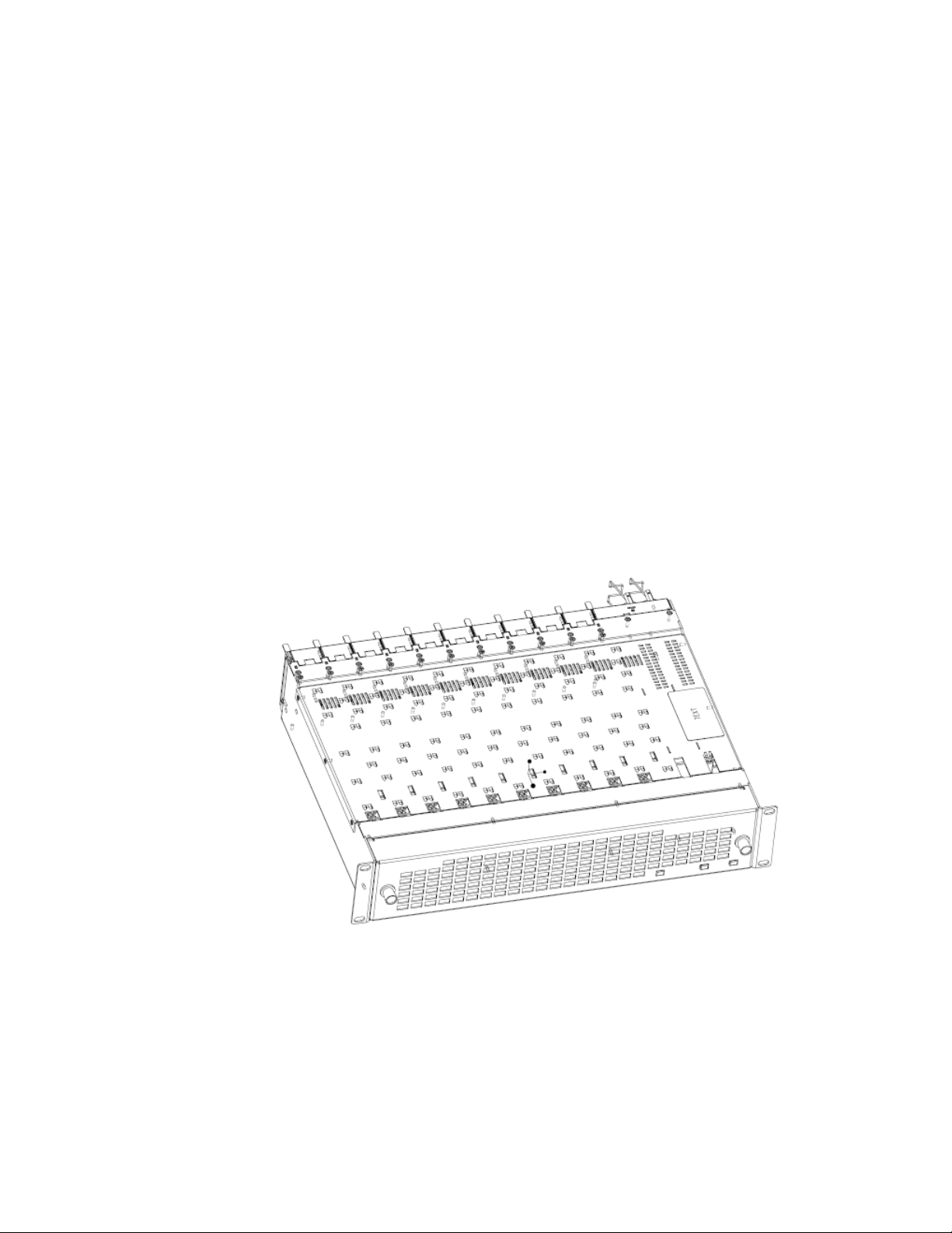
There are ten front and rear cell locations in the 2 RU GeckoFlex frame
Figure 1) to accommodate either audio, analog and digital video modules.
(
Figure 1. GeckoFlex Frame
10 8939FCA/FCB — Instruction Manual
Page 11

Module Installation Precautions
Please read and follow the precautions listed below before installing the
8939FCA and 8939FCB rear modules:
• Use standard anti-static procedures during installation. As modules
can be installed or removed when the GeckoFlex frame is powered up,
before removing the cover, please use an anti-static bracelet tied to a
metal part of the frame.
• When installing or removing a rear module, loosen or tighten the
screws holding the retainer clips to the frame manually with the
retainer clip tool provided inside the front cover of the frame or use a
2 mm (5/64”) hex screwdriver. Please do not use an electric screwdriver.
Note On newer 751- version GeckoFlex frames, a Rear Retainer Clip removal tool
and 2 extra retainer clips and screws for installing them are provided on the
inside of the frame cover.
• Make every effort to leave the screws holding the retainer clips in place
(do not remove them completely). They are very small and can easily
drop into other equipment causing a shorting hazard. (Two turns of the
screw should be enough to loosen the screws, 3 turns or more will
remove it.)
Installation
• When installing a rear module, tighten the screws on the retainer clips
just until snug. Do not apply more force than is necessary to seat the
rear module. The retainer clip screw torque specification is given in the
Mechanical specifications in Table 1 on page 28.
• If using a fiber optic SFP device, handle it carefully, use anti-static precautions, and read the Fiber Optic Cleaning Requirement below before
cabling.
Fiber Optic Cleaning Requirement
Before making any fiber optic cable mating connections and after every
de-mating cycle, use an industry standard fiber optic cleaning kit,
including oil-free compressed air, to clean the fiber connectors and the con
nectorized fiber end faces. This helps ensure optimum performance of the
fiber optic interface. Industry standard fiber optic cleaning kits can be pur
chased on the web and in electronics stores.
-
-
8939FCA/FCB — Instruction Manual 11
Page 12

Installation
8939FCA and 8939FCB Installation
Each rear module or blank rear adapter cover is held in place by two rear
retainer strips as shown in
To install an 8939FCA or 8939FCB module into the frame, follow these
steps:
1. Loosen (but do not remove completely) the two screws holding each
retainer strip to the frame with a 2 mm (5/64”) hex screwdriver. Pull up
on the retainer to remove it, leaving the screws in place.
CAUTION Be careful to leave the screws in place as they can be easily lost or fall into
equipment below the frame creating a shorting hazard.
2. Remove the blank cover using the retainer removal tool included on the
inside cover of the frame or needlenose pliers.
3. Insert the 8939FCA or 8939FCB module into the empty slot by lining up
the metal card guides on the top and bottom of the module with the
card guides in the frame.
Figure 2.
4. Once the module is firmly in place, replace each retainer strip over the
two screws on both sides of the module and push down to seat it.
5. Tighten the screws for each retainer just until they are snug. Do not
force or torque the screws too tightly. The retainer should not bend or
bow. The screw torque specification is given in Table 1 on page 28.
Figure 2. Installing 8939FCA or 8939FCB
12 8939FCA/FCB — Instruction Manual
Page 13

Cabling
Installation
Note Before making any fiber optic cable mating connections and after every
de-mating cycle, use an industry standard fiber optic cleaning kit to clean the
fiber connectors and the connectorized fiber end faces. Refer to Fiber Optic
Cleaning Requirement on page 11.
Cabling is done on the rear fiber connections of the 8939FCA and 8939FCB
modules. Each module is bi-directional and can act as an multiplexer or
demultiplexer in any combination. For common usage applications for the
8939FCA or 8939FCB modules, refer to
on page 16.
The modules only accept fiber inputs corresponding to the specific wavelengths labeled on the rear connectors. The fiber inputs can come from any
Grass Valley device that meets the specifications as described in
tions on page 28.
CAUTION This is a Class Ilia laser device. Use caution when cabling as fiber optic lasers
are present. Follow standard fiber optic laser safety recommendations when
handling these modules.
8939FCA and 8939FCB Applications
Specifica-
8939FCA Modules
The currently shipping 8939FCA module backplane is shown in Figure 3
on page 14 with the CWDM frequencies labeled for each channel. Earlier
versions of the 8939FCA module shipped with the backplane shown in
Figure 4 on page 14.
CAUTION Note that the COM and EXP ports in the older version do not have protective
The 8939FCA has eight fiber channels (CH 1 – CH 8), each handling a specific frequency as silkscreened on the module.
The COM port is the fiber link between other 8939FCA and 8939FCB modules. The single fiber connection can be up to 50 kilometers in length. Cable
lengths may require attenuation between COM ports in some instances.
Refer to
The EXP fiber port is used with devices with a 1310nm input or output. This
expansion port can accept or deliver an additional 1310nm wavelength
signal from GeckoFlex fiber-ready modules that are equipped with a fiber
optic SFP device.
Three different fiber optic receiver, transmitter, and transceiver SFP devices
can be installed on Grass Valley fiber-ready front modules to match the
required application.
Attenuation Requirements on page 15.
coverings. Use caution when cabling as these are laser outputs.
8939FCA/FCB — Instruction Manual 13
Page 14

Installation
8939FCA
1610nm input or output
1570nm input or output
1530nm input or output
1490nm input or output
CH1
1470nm
CH2
1490nm
CH4
1530nm
CH6
1570nm
CH8
1610nm
CH3
1510nm
CH5
1550nm
CH7
1590nm
EXPCOM
COM fiber optic connection
to other fiber modules
1590nm input or output
1550nm input or output
1510nm input or output
1470nm input or output
Expansion Port for
1310nm input or output
8558_01r1
Class IIIa
Laser Product
Figure 3. Current 8939FCA Backplane
1610nm input or output
1570nm input or output
1530nm input or output
1490nm input or output
COM fiber optic connection
to other 8939CFA module
Figure 4. Earlier Version 8939FCA Backplane
8939FCA
1590nm input or output
1550nm input or output
1510nm input or output
1470nm input or output
CH8
CH6
CH4
CH2
COM
CH7
CH5
CH3
CH1
EXP
8558_05r1
Expansion Port for
1310nm input or output
14 8939FCA/FCB — Instruction Manual
Page 15

8939FCB Modules
8939FCB
1430nm input or output
1390nm input or output
1350nm input or output
1310nm input or output
CH10
1330nm
CH9
1310nm
CH11
1350nm
CH13
1390nm
CH15
1430nm
CH12
1370nm
CH14
1410nm
CH16
1450nm
EXPCOM
COM fiber optic connection
to 8939FCA module
1450nm input or output
1410nm input or output
1370nm input or output
1330nm input or output
N/A
8558_09r0
Class IIIa
Laser Product
The pinouts for the 8939FCB module are shown in Figure 5. The 8939FCB
has eight fiber channels (CH 9 – CH 16), each handling a specific CWDM
frequency as silkscreened on the module.
Refer to 8939FCA Modules on page 13 the for cabling the COM and EXP
ports.
Figure 5. Current 8939FCB Backplane
Installation
Attenuation Requirements
Some shorter length cable runs will require attenuation to prevent overdriving the receiver causing bit errors to occur on the fiber link. Use the following guidelines for adding attenuation:
• The 1310nm Dual Transmitter (SFP-1310-SDTX) requires no attenuation
between the EXP ports at any cable lengths.
•CWDM SFP devices used with 8939FCA modules for a mux/demux
configuration with cable runs from 0-12 km (7.5 miles), must be attenuated by 3 dB between 8939FCA COM ports.
• All CWDM SFP devices used in a point-to-point configuration with a
cable run from 0-20 km (12.4 miles), must be attenuated by 5 dB
between fiber transmitter and receiver connections.
8939FCA/FCB — Instruction Manual 15
Page 16

8939FCA and 8939FCB Applications
8939FCA and 8939FCB Applications
Before using the 8939FCA and/or the 8939FCB, it is useful to understand
some basic configurations that utilize the full capabilities of the CWDM
fiber module series. The 8939FCA/FCB passive modules are excellent for
the following applications:
• Transporting multiple SD-SDI or HD-SDI video signals over a limited
fiber cable capacity.
• When reducing infrastructure costs (cabling, electrical power consumption, space, etc.) is required – multiplexed video over fiber gives an 8:1
ratio on cabling and support equipment.
• Fiber transport is commonly used in any application where HD-SDI
signals are found.
The 8939FCA and 8939FCB can act as a multiplexer or demultiplexer or as
a combination of both due to the bi-directionality of the passive optic
device.
Note Refer to Attenuation Requirements on page 15 to determine if attenuation is
needed in your application depending on the length of cable run between
8939FCA or 8939FCB COM ports.
The following three CWDM configuration examples using the 8943CF and
8943FC modules (handling up to 3 Gb/s) are given in this manual:
• CWDM Configuration for 9 Channels (page 17)
• CWDM 16 Channel Configuration (page 20)
• Bi-Directional Application (page 24)
Note As mentioned earlier, this manual uses the 8943CF 4 Channel Electrical to
Fiber and 8943FC 4 Channel Fiber to Electrical Converter modules for examples throughout the manual as they handle a higher bit rate of 3 Gb/s. 8935CF
and 8935FC 4 Channel converter modules can also be used in the same configuration and can handle bit rates up to 1.5 Gb/s. However, status reporting
for the 8935 modules may vary.
16 8939FCA/FCB — Instruction Manual
Page 17

CWDM Configuration for 9 Channels
8943CF
Coax 1-4 In
Fiber 1-4 Out
8943CF
Coax 5-8 In
Coax In
Fiber 1-4 Out
Fiber Out
8943FC
Fiber 1-4 In
Coax 1-4 Out
8943FC
Fiber 1-4 In
Fiber In
Coax 5-8 Out
Coax Out
8939FCA 8939FCA
GeckoFlex module
with 1310nm SFP
GeckoFlex module
with 1310nm SFP
8771_04r1
One use of CWDM involves the ability to multiplex and demultiplex up to
9 channels of video in as shown in the block diagram in
Figure 6. CWDM Block Diagram for 9 Channel Configuration
8939FCA and 8939FCB Applications
Figure 6.
To utilize this application, the following Grass Valley modules are needed:
• Two 8943CF 4 Channel Electrical to Fiber Converter modules with one
of each type of CWDM SFP devices. Refer to the 8943CF Instruction
Manual for complete SFP device installation instructions.
• Two 8943FC 4 Channel Fiber to Electrical Converter modules with one
of each type of CWDM SFP devices. Refer to the 8943FC Instruction
Manual for for complete SFP device installation instructions.
• Two fiber-ready Grass Valley GeckoFlex modules with 1310nm SFP
devices. Refer to the specific fiber-ready module Instruction Manual for
for complete SFP device installation instructions.
8939FCA/FCB — Instruction Manual 17
Page 18

8939FCA and 8939FCB Applications
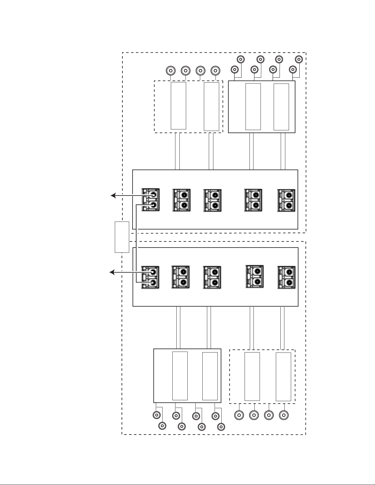
As shown in the detailed block diagram in Figure 7 on page 19, two 8943CF
(Electrical to Fiber converters) at Location A are used to feed 8 channels of
video to an 8939FCA.
To utilize this application, one of each of the following four CWDM SFP
device types must be installed on the two 8943CF modules:
• SFP-CWDM-1 Dual Transmitter (1490nm and 1470nm frequencies)
• SFP-CWDM-2 Dual Transmitter (1510nm and 1530nm frequencies)
• SFP-CWDM-3 Dual Transmitter (1550nm and 1570nm frequencies)
• SFP-CWDM-4 Dual Transmitter (1590nm and 1610nm frequencies)
Note The four SFP devices can be installed in any location on the two 8943CF
The 1310nm fiber output from a Grass Valley GeckoFlex module is cabled
to the EXP (Expansion) port on the 8939FCA.
The 8939FCA module multiplexes these 9 frequencies down to a single
output from the COM port. A single fiber cable carries these 9 video fiber
channels to the COM port of the 8939FCA at Location B.
modules as long as the outputs are cabled to the correct frequency input on
the 8939FCA.
The 8939FCA at Location B acts as a demultiplexer accepting the incoming
fiber signals and outputting electrical outputs from the 8943FC (fiber to
electrical) modules, each with two SFP-DRX-1-K Dual Receiver SFP devices
installed and a Grass Valley fiber-ready module. The SFP-DRX-1 SFP
device will accept input frequencies from 1270nm to 1610nm.
18 8939FCA/FCB — Instruction Manual
Page 19

Coax
Ouputs
Figure 7. 9 Channel Mux/Demux Application
Ch 1
Ch 2
Ch 1
Outputs
Electrical
4
3
Ch 2
Ch 3
Ch 3
8939FCA and 8939FCB Applications
Ch 4
Ch 4
Ch 1
Ch 1
Ch 2
Ch 2
Ch 3
Ch 3
Ch 4
Ch 4
8772_04r1
1310-DRL
Submodule
GeckoFlex Fiber-Ready Module
for inline
attenuation
( see note
*
requirements)
8935FC Fiber Inputs
1
2
8939FCA
Demultiplexer
up to 50km
Distance of
Single-mode fiber cable
IN IN
8943FC
COM EXP
Connector J4
SFP-13103G-M1DRX-K
Fiber In 1
from 1610nm
Connector J6
1270 > 1610nm
Fiber In 3
Fiber In 2
from 1590nm
CH7
1590nm
CH8
1610nm
CH7
1590nm
8943FC
1270 > 1610nm
SFP-13103G-M1DRX-K
Fiber In 4
from 1570nm
from 1550nm
CH5
1550nm
CH4
1570nm
CH5
1550nm
Connector J4
Fiber In 1
Connector J6
1270 > 1610nm
SFP-13103G-M1DRX-K
Fiber In 2
from 1530nm
CH3
1510nm
CH4
1530nm
CH3
1510nm
SFP-13103G-M1DRX-K
Fiber In 3
from 1490nm
from 1510nm
CH1
CH2
CH1
1270 > 1610nm
Fiber In 4
from 1470nm
1470nm
1490nm
1470nm
Fiber Out
8939FCA
Multiplexer
4
3
COM EXP
CH8
1610nm
Fiber Out 2
Fiber Out 1
to 1610nm
to 1570nm
to 1590nm
Fiber Out 3
CH4
1570nm
to 1550nm
Fiber Out 4
CH4
1530nm
to 1530nm
Fiber Out 1
Fiber Out 2
CH2
to 1490nm
to 1510nm
Fiber Out 3
1490nm
to 1470nm
Fiber Out 4
Location A Location B
SFP-13103G-M1DTX
GeckoFlex Fiber-Ready Module
Coax In
OUT OUT
8935CF Fiber Outputs
1
2
Inputs
Electrical
8943CF
Connector J6
Ch 1
SFP-CWDM3G-4-K
Ch 2
Connector J4
1590nm & 1610nm
Ch 3
SFP-CWDM3G-3-K
Ch 4
8943CF
Connector J6
1550nm & 1570nm
Ch 1
Ch 2
Connector J4
Ch 3
SFP-CWDM3G-1-K
Ch 4
SFP-CWDM3G-2-K
1510nm & 1530nm
1470nm & 1490nm
Note: In this configuration (8959FCA to 8939FCA utilizing CWDM transmitters), if the distance between 8939FCA modules is less than 12 km (7.5 m),
a 3 dB attenuator must be installed somewhere between the COM ports on the 8939FCA modules to prevent overdriving the receiver causing bit errors
*
8939FCA/FCB — Instruction Manual 19
to occur on the link.
Page 20

8939FCA and 8939FCB Applications
CWDM 16 Channel Configuration
The 8943CF and 8943FC 4 Channel Converter modules can also be used
with two 8939FCA and two 8939FCB modules to provide 16 channels of
video over a single fiber connection.
As shown in the simple block diagram in Figure 8 on page 21, the two
8939FCB module COM ports can be connected to the corresponding
8939FCA module EXP ports to provide another eight channels of video, for
a total of 16 channels over one fiber.
Multiplexing 8939FCA/FCB
The multiplexing 8939FCA is fed signals from two 8943CF modules with
fiber optic SFP devices with frequencies pairs from 1470nm to 1610nm
(CH1 – CH8).
The multiplexing 8939FCB is fed signals in a similar manner as the
8939FCA from two 8943CF module with fiber optic SFP devices with fre
quencies pairs from 1310nm to 1450nm (CH9 – CH16).
-
The multiplexing 8939FCB COM port is then connected to the EXP port of
the multiplexing 8939FCA allowing the 16 channels to be sent out the COM
port of the 8939FCA over fiber to the demultiplexing 8939FCA COM port.
Demultiplexing 8939FCA/FCB
The demultiplexing 8939FCA COM port accepts the 16 channels over a
single fiber. The 8939FCA EXP port is connected to the COM port of the
demultiplexing 8939FCB allowing the 16 channels of fiber to be separated
by the optical filtering in both modules and sent to the corresponding fre
quency output ports on the 8939FCA and 8939FCB.
These fiber outputs are connected to four 8943FC 4 Channel Fiber to Electrical modules each with two CWDM fiber receiver SFP devices installed
that will accept bit rates of 1270nm to 1610nm.
The 8939FCA/FCB outputs must be cabled to the fiber inputs on the
8943FC modules so that all electrical output channels match the electrical
input channels. The 8943FC modules make the original electrical inputs
available on the electrical outputs of the module.
-
20 8939FCA/FCB — Instruction Manual
Page 21

8939FCA and 8939FCB Applications
COM
EXP
8939FCA
Single-mode Fiber (up to 50 km)
8939FCA
(1470nm) Ch1 TX
(1490nm) Ch2 TX
(1510nm) Ch3 TX
(1530nm) Ch4 TX
(1550nm) Ch5 TX
(1570nm) Ch6 TX
(1590nm) Ch7 TX
(1610nm) Ch8 TX
COM
Ch1 RX (1270 to 1610nm)
Ch2 RX (1270 to 1610nm)
Ch3 RX (1270 to 1610nm)
Ch4 RX (1270 to 1610nm)
Ch5 RX (1270 to 1610nm)
Ch6 RX (1270 to 1610nm)
Ch7 RX (1270 to 1610nm)
Ch8 RX (1270 to 1610nm)
COM
8939FCB
8943CF
8939FCB
(1310nm) Ch9 TX
(1330nm) Ch10 TX
(1350nm) Ch11 TX
(1370nm) Ch12 TX
(1390nm) Ch13 TX
(1410nm) Ch14 TX
(1430nm) Ch15 TX
(1450nm) Ch16 TX
COM
Ch9 RX (1270 to 1610nm)
Ch10 RX (1270 to 1610nm)
Ch11 RX (1270 to 1610nm)
Ch12 RX (1270 to 1610nm)
Ch13 RX (1270 to 1610nm)
Ch14 RX (1270 to 1610nm)
Ch15 RX (1270 to 1610nm)
Ch16 RX (1270 to 1610nm)
MUX
DEMUX
MUX
DEMUX
EXP
EXP (N/A)(N/A) EXP
8543_13r0
8943FC
8943FC
8943FC
8943FC
8943CF
8943CF
8943CF
Figure 8. 8939FCA and 8939FCB Simple Block Diagram
8939FCA/FCB — Instruction Manual 21
Page 22

8939FCA and 8939FCB Applications
To utilize a 16 channel configuration using 8939FCA and 8939FCB modules, follow the setup below.
Use the same configuration for the 8943CFs to the 8939FCA as shown in
CWDM Configuration for 9 Channels on page 17. You will be using the
8939FCA EXP ports to connect to the 8939FCB COM port instead of a
1310nm GeckoFlex fiber-ready module.
Refer to the detailed diagram of the channel 1-8 8939FCA confutation in
Figure 7 on page 19. For channels 1-8, two 8943CF modules must feed the
multiplexing 8939FCA with two of the following fiber optic SFP devices
installed:
• SFP-CWDM3G-1-K Dual Transmitter (1490nm/1470nm frequencies)
• SFP-CWDM3G-2-K Dual Transmitter (1510nm/1530nm frequencies)
• SFP-CWDM3G-3-K Dual Transmitter (1550nm/1570nm frequencies)
• SFP-CWDM3G-4-K Dual Transmitter (1590nm/1610nm frequencies)
Refer to the detailed diagram of the channel 9-16 in Figure 9 on page 23. For
channels 9-16, two 8943CF modules must feed the multiplexing 8939FCB
with two of the following fiber optic SFP devices installed:
• SFP-CWDM3G-5-K Dual Transmitter (1310nm/1330nm frequencies)
• SFP-CWDM3G-6-K Dual Transmitter (1350nm/1370nm frequencies)
• SFP-CWDM3G-7-K Dual Transmitter (1390nm/1410nm frequencies)
• SFP-CWDM3G-8-K Dual Transmitter (1430nm/1450nm frequencies)
The four 8943FC 4 Channel Fiber to Electrical modules receiving the fiber
from the demultiplexing 8939FCA and 8939FCB should have
SFP-13103G-M1DRX-K Dual Receivers SFP devices installed in all SFP
locations. These SFP devices will receive frequencies from 1270nm to
1610nm. For clarity, the fiber outputs are cabled to the same channel as the
original coax input.
22 8939FCA/FCB — Instruction Manual
Page 23

8939FCA and 8939FCB Applications
8772_05r1
8939FCA
8943CF
Fiber Out 1
to 1450nm
Fiber In 1
from 1450nm
Fiber In 2
from 1430nm
Fiber In 3
from 1410nm
Fiber In 4
from 1390nm
Fiber Out 3
to 1410nm
Fiber Out 4
to 1390nm
Fiber Out 2
to 1430nm
Fiber Out 1
to 1370nm
Fiber Out 3
to 1330nm
Fiber Out 4
to 1310nm
Fiber Out 2
to 1350nm
Electrical
Inputs
To 8939FCA
DEMUX COM port
To 8939FCA
MUX COM port
Multiplexer
Demultiplexer
Connector J6
Connector J4
8943CF
SFP-CWDM3G-7-K
1390nm & 1410nm
Fiber In 1
from 1370nm
Fiber In 2
from 1350nm
Fiber In 3
from 1330nm
Fiber In 4
from 1310nm
Connector J6
SFP-CWDM3G-8-K
1430nm & 1450nm
Connector J4
SFP-CWDM3G-5-K
1310nm & 1330nm
SFP-CWDM3G-6-K
1350nm & 1370nm
8943FC
Connector J6
Connector J4
Connector J6
SFP-1310-M1DRX-K
1270 > 1610nm
SFP-1310-M1DRX-K
1270 > 1610nm
SFP-1310-M1DRX-K
1270 > 1610nm
SFP-1310-M1DRX-K
1270 > 1610nm
Connector J4
COM EXP
CH9
1310nm
CH10
1330nm
CH12
1370nm
CH11
1350nm
CH14
1410nm
CH13
1390nm
CH16
1450nm
CH15
1430nm
8939FCA
COM EXP
CH9
1310nm
CH10
1330nm
CH12
1370nm
CH11
1350nm
CH14
1410nm
CH13
1390nm
CH16
1450nm
CH15
1430nm
8943FC
Electrical
Outputs
Location A Location B
8943FC Fiber Inputs
1
2
4
3
IN IN
8943CF Fiber Outputs
1
2
4
3
OUT OUT
Ch 1
Ch 2
Ch 3
Ch 4
Ch 1
Ch 2
Ch 3
Ch 4
Ch 1
Ch 3
Ch 4
Ch 2
Ch 1
Ch 2
Ch 3
Ch 4
Ch 1
Ch 3
Ch 4
Ch 2
Ch 1
Ch 2
Ch 3
Ch 4
Note: In any configuration utilizing CWDM transmitters, if the distance between 8939FCA modules is less than 12 km (7.5 m),
a 3 dB attenuator must be installed somewhere between the COM ports on the 8939CFA modules to prevent overdriving the receiver causing bit errors
to occur on the link.
*
Single-mode fiber cable
*
Distance of
up to 50km
Figure 9. 8939FCB Configuration
8939FCA/FCB — Instruction Manual 23
Page 24

8939FCA and 8939FCB Applications
8939FCA
8939FCA
Ch7 RX
Ch8 RX
Ch3 TX
Single-mode
8558_11r0
Ch4 TX
Ch1 TX
To 8939FCB COM ports
for additional channels
Ch5 RX
Ch6 RX
Ch1 RX
Ch2 RX
Ch2 TX
Ch3 RX
Ch4 RX
Ch5 TX
Ch6 TX
Ch7 TX
Ch8 TX
EXP
8943CF CH 1-4
8943CF CH 5-8
8943FC CH1-4
8943FC CH 5-8
EXP
COM
COM
Bi-directional Application
This section illustrates how the 8939FCA and/or 8939FCB can be used in a
bi-directional application. Four channels (1-4) can mux/demux four
signals in one direction while the other four channels (5-8) on the same
modules can mux/demux four signals in the opposite direction. When the
8939FCB COM port is connected to the 8939FCA via the EXP port, the
module can mux and demux up to 16 channels in two directions in any
combination.
A block diagram of the 8939FCA in a simple bi-directional application is
shown in
the 8939FCB COM port.
Figure 10. Bi-directional Simple Block Diagram
Figure 10. For more channels (9-16), connect the 8939FCA EXP to
To utilize this application example, the following Grass Valley modules are
needed in two locations:
• One 8943CF 4 Channel Electrical to Fiber Converter modules and one
8943FC Fiber to Electrical module
• Two 8939FCA modules
24 8939FCA/FCB — Instruction Manual
Page 25

8939FCA and 8939FCB Applications
As shown in the detailed block diagram in Figure 11 on page 26, an 8943CF
(4 Channel Electrical to Fiber converter) and an 8943FC (4 Channel Fiber to
Electrical converter) at Location A are used to send 4 channels of video to
an 8939FCA. To utilize this application, one of each of the following four
CWDM SFP device types must be installed on the two 8943CF modules:
• SFP-CWDM3G-1-K Dual Transmitter (1490nm/1470nm frequencies)
• SFP-CWDM-2 Dual Transmitter (1510nm/1530nm frequencies)
• SFP-CWDM-3 Dual Transmitter (1550nm/1570nm frequencies)
• SFP-CWDM-4 Dual Transmitter (1590nm/1610nm frequencies)
Note The four SFP devices can be installed in any location on the two 8943CF
modules as long as the outputs are cabled to the correct frequency input on
the 8939FCA.
The 8939FCA module multiplexes these 8 frequencies down to a single
output from the COM port. A single fiber cable carries these 8 video fiber
channels to the COM port of the 8939FCA at Location B.
The 8939FCA at Location B acts as a demultiplexer and outputs 8 fiber
video channels to two 8943FC (fiber to electrical) modules, each with two
SFP-DRX-1 Dual Receiver SFP devices installed and a Grass Valley
fiber-ready module. The SFP-DRX-1 SFP device will accept input frequen
cies from 1270nm to 1610nm.
-
8939FCA/FCB — Instruction Manual 25
Page 26
8939FCA and 8939FCB Applications
Figure 11. Bi-directional Application
8558_02r1
Ch1InCh2InCh3InCh4
8943CF
Connector J4
SFP-CWDM3G-4-K
1590nm & 1610nm
Location B
Fiber Out
to 1610nm
Fiber Out
8939FCA
EXP
COM
CH7
CH8
1590nm
1610nm
Connector J6
to 1610nm
Fiber Out
to 1610nm
In
Ch1 Out
8943FC
Connector J4
SFP-CWDM3G-3-K
1550nm & 1570nm
Fiber Signal
Fiber Out
to 1610nm
CH5
1550nm
CH6
1570nm
Ch2 Out
from 1530nm
Ch3 Out
Connecotr J6
1270 > 1610nm
SPF-13103G-M1DRX-K
Fiber Signal
CH3
1510nm
CH4
1530nm
SPF-13103G-M1DRX-K
Fiber Signal
from 1490nm
from 1510nm
CH2
Ch4 Out
1270 > 1610nm
Fiber Signal
from 1470nm
CH1
1470nm
1490nm
up to 50km
Distance of
CH7
1590nm
Connect to 8939FCB COM port for more channels
CH8
1610nm
Fiber Signal
from 1610nm
Fiber Signal
from 1590nm
8939FCA
COM EXP
Location A
8943FC
Connector J4
1270 > 1610nm
SPF-13103G-M1DRX-K
CH5
1550nm
CH6
1570nm
Fiber Signal
from 1570nm
Fiber Signal
from 1550nm
Connector J6
1270 > 1610nm
SPF-13103G-M1DRX-K
CH3
CH4
Fiber Out
to 1530nm
8943CF
Connector J4
SFP-CWDM3G-4-K
1510nm
1530nm
Fiber Out
to 1510nm
CH1
1470nm
CH2
1490nm
to 1490nm
Fiber Out
Fiber Out
Connector J6
SFP-CWDM3G-4-K
1510nm & 1530nm
1490nm & 1470nm
to 1470nm
Ch1Out
Ch2 Out
Ch3 Out
Ch4 Out
Ch1InCh2InCh3InCh4
In
Note: In this configuration (8959CFA to 8939CFA utilizing CWDM transmitters), if the distance between 8939CFA modules is less than 12 km (7.5 m),
a 3 dB attenuator must be installed somewhere between the COM ports on the 8939CFA modules to prevent overdriving the receiver causing bit errors
*
26 8939FCA/FCB — Instruction Manual
to occur on the link.
Page 27

Configuration and Monitoring
The 8939FCA and 8939FCB modules require no configuration and as they
are passive modules. They are only monitored for their presence in the
frame, slots 3, 4, 7, and 8 in this example shown in
Figure 12. 8939FCA/FCB Presence in Frame
Configuration and Monitoring
Figure 12.
Selecting the link to the 8939 module web page will report an empty slot as
shown for the module in slot 4 shown in
Figure 13. 8939FCA Module Web Page
Figure 13.
8939FCA/FCB — Instruction Manual 27
Page 28

Specifications
Specifications
Ta bl e 1 gives the specifications for the 8939FCA and the 8939FCB modules..
Table 1. 8939FCA/FCB Specifications
Parameter Value
Performance
8939FCA 8 Channel CWDM channels Ch 1: 1470nm
8939FCB 8 Channel CWDM channels Ch 9: 1310nm
8 channel insertion loss 2.25 dB maximum
8 channel link loss 4 dB maximum
8 channel uniformity 1.25 dB
Expansion Port
Wavelength coverage FCA: 1270nm >1450nm FCB:
Insertion loss 1.25 dB maximum
Adjacent channel isolation 35 dB typical
Non-adjacent channel isolation 50 dB
Polarization dependent loss 0.1 dB
Optical return loss 50 dB minimum
Optical ripple 0.5 dB maximum
Thermal stability 0.005nm/degrees C
Mechanical
Frame type GeckoFlex
Number of slots required 1 rear slot
Rear module retainer clip screw torque 4-5 inch-lb./0.45-0.6Nm
Environmental
Storage temperature
Operating ambient temperature
Power rating and size 0.0 W (passive) -single slot one piece rear mount
Ch 2: 1490nm
Ch 3: 1510nm
Ch 4: 1530nm
Ch 5: 1550nm
Ch 6: 1570nm
Ch 7: 1590nm
Ch 8: 1610nm
Ch 10: 1330nm
Ch 11: 1350nm
Ch 12: 1370nm
Ch 13: 1390nm
Ch 14: 1410nm
Ch 15: 1430nm
Ch 16: 1450nm
Refer to GeckoFlex Frames 8900FX/FF/FFN Signal Processing Systems
Instruction Manual at www.grassvalley.com/docs/modular
28 8939FCA/FCB — Instruction Manual
Page 29

Specifications
Table 2. Optional Dual Transmitter/Transceiver Specifications
SFP-13103G
-M1DTX-K
Model Numbers
SFP-13103G
-M1DTX
SFP-13103G
-M2DTX
SFP-CWDM3G-1-K
SFP-CWDM3G-1
SFP-CWDM3G-2-K
SFP-CWDM3G-2
SFP-CWDM3G-3-K
SFP-CWDM3G-3
SFP-CWDM3G-4-K
SFP-CWDM3G-4
Wavelength 1 1310nm 1470nm 1510nm 1550nm 1590nm 1310nm
Wavelength 2 1310nm 1490nm 1530nm 1570nm 1610nm N/A
Model Numbers
SFP-CWDM3G-5-K
SFP-CWDM3G-5
SFP-CWDM3G-6-K
SFP-CWDM3G-6
SFP-CWDM3G-7-K
SFP-CWDM3G-7
SFP-CWDM3G-8-K
SFP-CWDM3G-8
Wavelength 1 1310nm 1350nm 1390nm 1430nm
Wavelength 2 1330nm 1370nm 1410nm 1450nm
Transmit Channels 2 2 2 2 2 1
Optical connectors LC
Fiber support Single-mode
Data Rate 143 Mb/s to 2.9 Gb/s
Power Output
@ 2.97 Gb/s,
360 Mb/s, and 270 Mb/s
TX power:
-7 to +2dBm
(± 3dB)
TX Power: -2 to +5dBm
(+3dB)
Maximum Distance with
SFP-13103G-M1DRX-K
SFP-13103G-M1DRX
10 km 50 km 30 km
SFP-13103G-M2DRX
@ 2.97 Gb/s
Maximum Distance with
SFP-13103G-M1DRX-K
SFP-13103G-M1DRX
20 km 60 km 20 km
SFP-13103G-M2DRX
@ 2.97 Gb/s
Minimum Distance with
SFP-13103G-M1DRX-K
SFP-13103G-M1DRX
0 km (See Note
1
)
0 km (see Note2)
SFP-13103G-M2DRX
@ 2.97 Gb/s
Minimum Distance with
SFP-13103G-M1DRX-K
SFP-13103G-M1DRX
N/A 50 km (see Note
3
)
SFP-13103G-M2DRX
@ 2.97 Gb/s
Optical Input Wavelength N/A
1
The 1310nm Dual Transmitter (SFP-13103G-M1DTX) and Transceiver (SFP-13103G-M1TRX, SFP-13103G-M2TRX) require no attenuation between fiber transmitter
and receiver connections at any cable lengths.
2
All CWDM devices used in point-to-point configuration with a cable run from 0-20 km, must be attenuated by 6 dB between the fiber transmitter and receiver connections.
3
CWDM devices used with 8939FCA or 8939FCA/8939FCB modules for a mux/demux configuration with a cable run from 0-12 km (7.5 miles), must be attenuated by
4 dB between 8939FCA or the 8939FCA/8939FCB COM ports.
SFP-13103G
-M1TRX-K
SFP-13103G
-M1TRX
SFP-13103G
-M2TRX
TX Power:
-7 to +2dBm
RX Power:
-22 to -1 dB
(± 3dB)
0 km (See Note1)
N/A
8939FCA/FCB — Instruction Manual 29
Page 30

Specifications
Table 3. Optional SFP Receiver/Transceiver Fiber Optic SFP Device Specifications
SFP-13103G-M1DRX-K
Model Numbers
Low wavelength 1270nm 1270nm
High wavelength 1610nm 1610nm
Receiver channels 2 1
Connector type LC
Fiber support Single-mode
Data rate 143 Mb/s to 2.97 Gb/s
Maximum Receive Signal Levels @ 2.97 Gb/s,
360 Mb/s, and 270 Mb/s
Minimum Receive Signal Levels @ 2.97 Gb/s,
360 Mb/s, and 270 Mb/s
SFP-13103G-M1DRX,
SFP-13103G-M2DRX
(0.500794 mW)
SFP-13103G-M1TRX-K
SFP-13103G-M1TRX
SFP-13103G-M2TRX
-3 dBm
(0.501 mW)
-23 dBm
30 8939FCA/FCB — Instruction Manual
Page 31

Index
Numerics
16 channel configuration 20
8939FCA
cabling
8939FCA/FCB
applications
features 9
in frame 27
specifications 28
web page 27
8939FCB
cabling
9 channel configuration 17
14
16
15
A
applications
16 channel mux/demux
9 channel mux/demux 17
Bi-directional 24
attenuation requirements 15
B
20
E
EXP port 13, 18
F
FAQ database 4
fiber optic cleaning kit 11, 13
frequently asked questions 4
G
GeckoFlex frame
module placement
rear view 12
Grass Valley web site 4
10
I
installation
8939FCA module
8939FCB module 12
precautions 11
procedure 10
12
Bi-directional application 24
M
C
cabling 13
8939FCA 14
8939FCB 15
COM port 13, 18
configuration 27
CWDM (Coarse Wavelength Division
Multiplexing)
16 channel configuration
9 channel configuration 17
20
module installation precautions 11
monitoring
web browser
27
O
online documentation 4
R
rear module
installation precautions
11
D
documentation online 4
8939FCA/FCB — Instruction Manual 31
Page 32

Index
S
software download from web 4
W
web site
documentation
FAQ database 4
Grass Valley 4
software download 4
4
32 8939FCA/FCB — Instruction Manual
 Loading...