

Page 1
8937/8937D
SDI RECLOCKING EQ SNMP DA MODULES
Instruction Manual
SOFTWARE VERSION 1.0.0
071827000
FEBRUARY 2004
Page 2

Contacting Grass Valley
Region Voice Fax Address Web Site
North America (800) 547-8949
Support: 530-478-4148
Pacific Operations +852-2585-6688
Support: 852-2585-6579
U.K., Asia, Middle East +44 1753 218 777 +44 1753 218 757
France +33 1 45 29 73 00
Germany, Europe +49 6150 104 782 +49 6150 104 223
Copyright © Thomson Broadcast and Media Solutions All rights reserved.
Grass Valley Web Site
Sales: (530) 478-3347
Support: (530) 478-3181
+852-2802-2996
Grass Valley
P.O. Box 599000
Nevada City, CA 959597900 USA
www.thomsongrassvalley.com
The www
Online User Documentation
.thomsongrassvalley.com web site offers the following:
— Current versions of product catalogs, brochures,
data sheets, ordering guides, planning guides, manuals, and release notes
in .pdf format can be downloaded.
FAQ Database
— Solutions to problems and troubleshooting efforts can be
found by searching our Frequently Asked Questions (FAQ) database.
Software Downloads
— Software updates, drivers, and patches can be down-
loaded.
2 8937/8937D Instruction Manual
Page 3

Contents
Preface
. . . . . . . . . . . . . . . . . . . . . . . . . . . . . . . . . . . . . . . . . . . . . . . . . . . . . . . . . . . . . . . . . . . . . 5
About This Manual . . . . . . . . . . . . . . . . . . . . . . . . . . . . . . . . . . . . . . . . . . . . . . . . . . . . . 5
8937 and 8937D Reclocking EQ SNMP DAs
Introduction . . . . . . . . . . . . . . . . . . . . . . . . . . . . . . . . . . . . . . . . . . . . . . . . . . . . . . . . . . . 7
Installation . . . . . . . . . . . . . . . . . . . . . . . . . . . . . . . . . . . . . . . . . . . . . . . . . . . . . . . . . . . . 8
Frame Capacity . . . . . . . . . . . . . . . . . . . . . . . . . . . . . . . . . . . . . . . . . . . . . . . . . . . . . . 8
Module Placement in the Gecko 8900 Frame . . . . . . . . . . . . . . . . . . . . . . . . . . . . . 8
Module On-board Jumper Settings. . . . . . . . . . . . . . . . . . . . . . . . . . . . . . . . . . . . . 10
8937 Module . . . . . . . . . . . . . . . . . . . . . . . . . . . . . . . . . . . . . . . . . . . . . . . . . . . . . . 10
8937D Module. . . . . . . . . . . . . . . . . . . . . . . . . . . . . . . . . . . . . . . . . . . . . . . . . . . . . 11
Looping Capabilities . . . . . . . . . . . . . . . . . . . . . . . . . . . . . . . . . . . . . . . . . . . . . . . 11
Cabling . . . . . . . . . . . . . . . . . . . . . . . . . . . . . . . . . . . . . . . . . . . . . . . . . . . . . . . . . . . . 12
8937 Module . . . . . . . . . . . . . . . . . . . . . . . . . . . . . . . . . . . . . . . . . . . . . . . . . . . . . . 12
8737D Module. . . . . . . . . . . . . . . . . . . . . . . . . . . . . . . . . . . . . . . . . . . . . . . . . . . . . 13
Power Up . . . . . . . . . . . . . . . . . . . . . . . . . . . . . . . . . . . . . . . . . . . . . . . . . . . . . . . . . . . . 14
Operation Indicator LEDs . . . . . . . . . . . . . . . . . . . . . . . . . . . . . . . . . . . . . . . . . . . . 14
Configuration. . . . . . . . . . . . . . . . . . . . . . . . . . . . . . . . . . . . . . . . . . . . . . . . . . . . . . . . . 16
Remote Control and Monitoring. . . . . . . . . . . . . . . . . . . . . . . . . . . . . . . . . . . . . . . 16
8937 and 8937D Links and Web Pages . . . . . . . . . . . . . . . . . . . . . . . . . . . . . . . . 18
Status Web Page. . . . . . . . . . . . . . . . . . . . . . . . . . . . . . . . . . . . . . . . . . . . . . . . . . . 19
Standard Selections Web Page. . . . . . . . . . . . . . . . . . . . . . . . . . . . . . . . . . . . . . . 20
Recall Factory Defaults Web Page. . . . . . . . . . . . . . . . . . . . . . . . . . . . . . . . . . . . 24
Slot Config Web Page . . . . . . . . . . . . . . . . . . . . . . . . . . . . . . . . . . . . . . . . . . . . . . 25
Software Update Web Page . . . . . . . . . . . . . . . . . . . . . . . . . . . . . . . . . . . . . . . . . 27
Newton Control Panel Configuration . . . . . . . . . . . . . . . . . . . . . . . . . . . . . . . . . . 28
Specifications . . . . . . . . . . . . . . . . . . . . . . . . . . . . . . . . . . . . . . . . . . . . . . . . . . . . . . . . . 29
Functional Description . . . . . . . . . . . . . . . . . . . . . . . . . . . . . . . . . . . . . . . . . . . . . . . . . 30
Input and Output Processing. . . . . . . . . . . . . . . . . . . . . . . . . . . . . . . . . . . . . . . . . . 30
Microprocessor and Input Selector . . . . . . . . . . . . . . . . . . . . . . . . . . . . . . . . . . . . . 30
Service. . . . . . . . . . . . . . . . . . . . . . . . . . . . . . . . . . . . . . . . . . . . . . . . . . . . . . . . . . . . . . . 31
Status Monitoring . . . . . . . . . . . . . . . . . . . . . . . . . . . . . . . . . . . . . . . . . . . . . . . . . . . . . 32
LEDs . . . . . . . . . . . . . . . . . . . . . . . . . . . . . . . . . . . . . . . . . . . . . . . . . . . . . . . . . . . . . . 32
Frame Alarm . . . . . . . . . . . . . . . . . . . . . . . . . . . . . . . . . . . . . . . . . . . . . . . . . . . . . . . 33
Web Browser Interface . . . . . . . . . . . . . . . . . . . . . . . . . . . . . . . . . . . . . . . . . . . . . . . 33
SNMP Reporting . . . . . . . . . . . . . . . . . . . . . . . . . . . . . . . . . . . . . . . . . . . . . . . . . . 34
Index
8937/8937D Instruction Manual 3
. . . . . . . . . . . . . . . . . . . . . . . . . . . . . . . . . . . . . . . . . . . . . . . . . . . . . . . . . . . . . . . . . . . . . . 35
Page 4

Contents
4 8937/8937D Instruction Manual
Page 5

Preface
About This Manual
This manual describes the features of a specific module of the Gecko 8900
Signal Processing System. As part of this module family, it is subject to
Safety and Regulatory Compliance described in the Gecko 8900 Series
frame and power supply documentation (see the
Frames Instruction Manual
).
8900TX/8900TF/8900TFN
8937/8937D Instruction Manual 5
Page 6

Preface
6 8937/8937D Instruction Manual
Page 7

8937 and 8937D Reclocking EQ SNMP DAs
Introduction
The 8937 module is a 1 x 8 looping input, auto-reclocking, auto-cable equalizing DA with SNMP monitoring capability. The module is suited for
medium to long distance signal distribution.
The 8937D (dual) module provides two separate SDI distribution amplifiers on a single card. It also has auto-reclocking, auto-cable equalizing with
SNMP monitoring capability. The module is ideal for environments where
compact and high density capability is required such as mobile trucks.
The 8937 and 8937D feature:
• Jumper selectable bypass/reclock mode with auto bypass,
•Auto detection and front panel indication of all SMPTE 259M signal
data rates,
•Auto format detection (525/625),
•Auto cable equalization for up to 300 meters of cable with front panel
EQ warning,
• Suitable for SMPTE 310M, SMPTE 259M, DVB-ASI, SDI 270 Mb/s and
other 800 mV data ranging from 4 Mb/s to 360 Mb/s,
• Signal presence indication with selectable SNMP trap generation, and
•Remote health monitoring interface.
This manual covers installation, configuration, and operation for both the
8937 and 8937D modules.
8937/8937D Instruction Manual 7
Page 8

Installation
Installation
Frame Capacity
1.
2.
Installation of a module is a process of:
The module can be plugged in and removed from a Gecko 8900 video
frame with power on. When power is applied to the module, LED indicators reflect the initialization process (see
The 8937 and 8937D module can be installed in all Gecko 8900 video frames
but with varying maximum quantities determined by frame cooling
capacity. Table 1 provides the power capacity, cooling capacity, and
maximum module count for each frame type.
Placing the module in a video frame slot, and
Cabling and terminating signal ports.
Power Up
on page 14).
Table 1. Video Frame Power Capacity
Capacity Calculated 8900TX Frame 8900TF Frame 8900TFN Frame
Power (W) 100 100 100
Recommended Module Cooling (W) 30 100 100
8937 Modules 10 10 10
8937D Modules 10 10 10
Note
Module capacity figures assume no other modules are in the frame.
Module Placement in the Gecko 8900 Frame
There are ten cell locations in the video frame to accommodate modules.
These are the left ten locations. Refer to Figure 1.
The two cells on the right are allocated for the power supplies. For additional information concerning the Power Supply module, refer to the 8900
Power Supply manual.
The third cell from the right is allocated for the Frame Monitor or 8900NET
Network Interface module. These modules provide health monitoring and
control options.
8 8937/8937D Instruction Manual
Page 9
1.
2.
3.
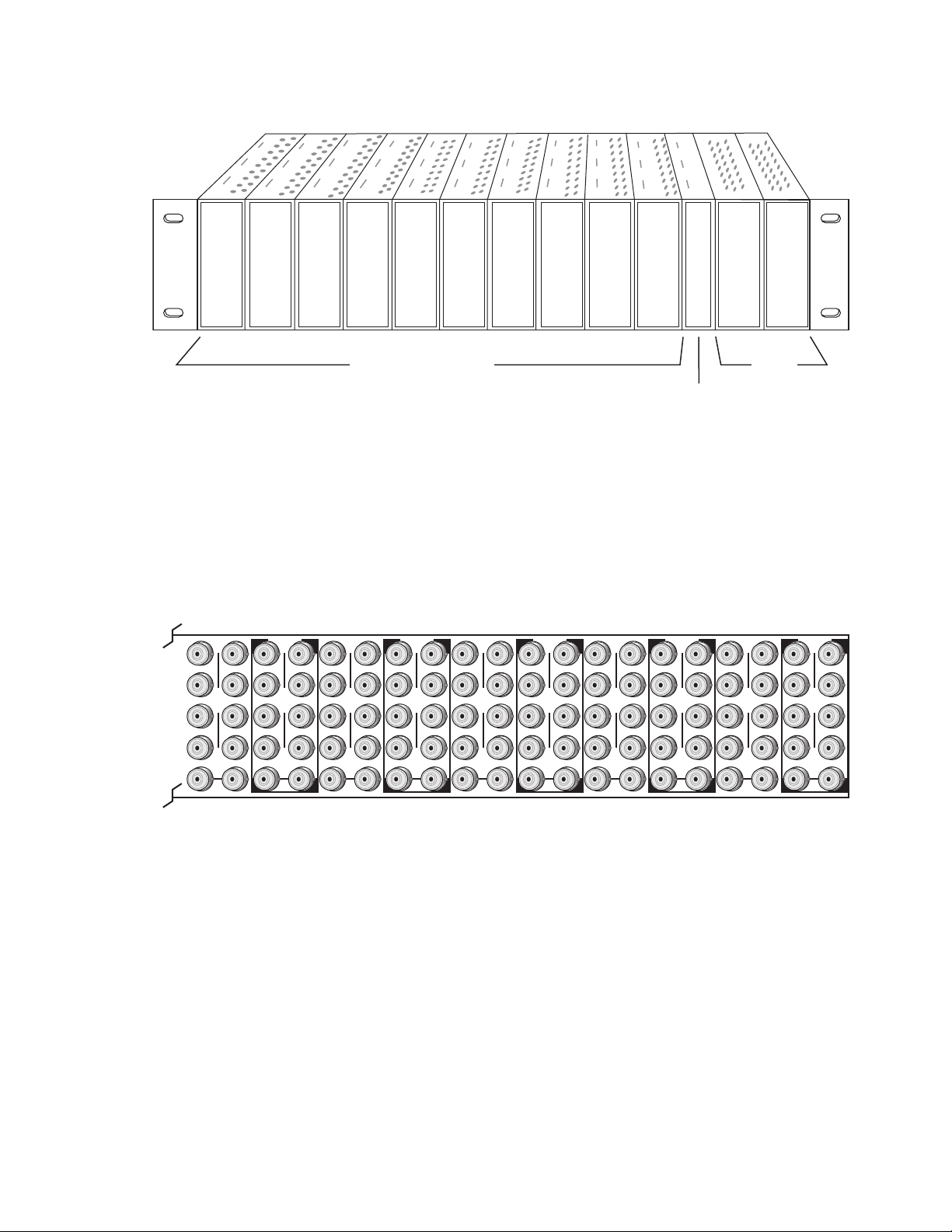
Figure 1. Gecko 8900 Series Frame
Installation
8270_02r1
DA10
J1 J2
O
J3 J4
U
T
J5 J6
J7 J8
J9 J10
IN
DA9
J1 J2
J2
O
J3 J4
J4
U
T
J5 J6
J6
J7 J8
J8
J9 J10
IN
Any Gecko/8900 Module
Power
Supplies
Frame Controller or
8900NET Network
Interface Module
8900 module slots are interchangeable within the frame. There are 10 BNCs
in each slot’s I/O group. The functional assignment of each connector in a
group is determined by the module that is placed in that slot. The
maximum number of modules a Gecko 8900 video frame can accept is ten.
Figure 2 illustrates the rear connector plate for a Gecko 8900 video frame.
Figure 2. Gecko 8900 Series Video Frame Rear Connector
DA8
J1 J2
O
J3 J4
U
T
J5 J6
J7 J8
J9 J10
IN
DA7
J1 J2
J2
O
J3 J4
J4
U
T
J5 J6
J6
J7 J8
J8
J9 J10
IN
DA6
J1 J2
O
J3 J4
U
T
J5 J6
J7 J8
J9 J10
IN
DA5
J1 J2
J2
O
J3 J4
J4
U
T
J5 J6
J6
J7 J8
J8
J9 J10
IN
DA4
J1 J2
O
J3 J4
U
T
J5 J6
J7 J8
J9 J10
IN
DA3
J2
J1 J2
O
J4
J3 J4
U
T
J6
J5 J6
J8
J7 J8
J9 J10
IN
DA2
J1 J2
O
J3 J4
U
T
J5 J6
J7 J8
J9 J10
IN
DA1
J1 J2
O
J3 J4
U
T
J5 J6
J7 J8
J9 J10
IN
8270_01
To install a module in the frame:
Insert the module, connector end first, with the component side of the
module facing to the right and the ejector tab to the top.
Verify that the module connector seats properly against the backplane.
Press in the ejector tab to seat the module.
8937/8937D Instruction Manual 9
Page 10
Installation
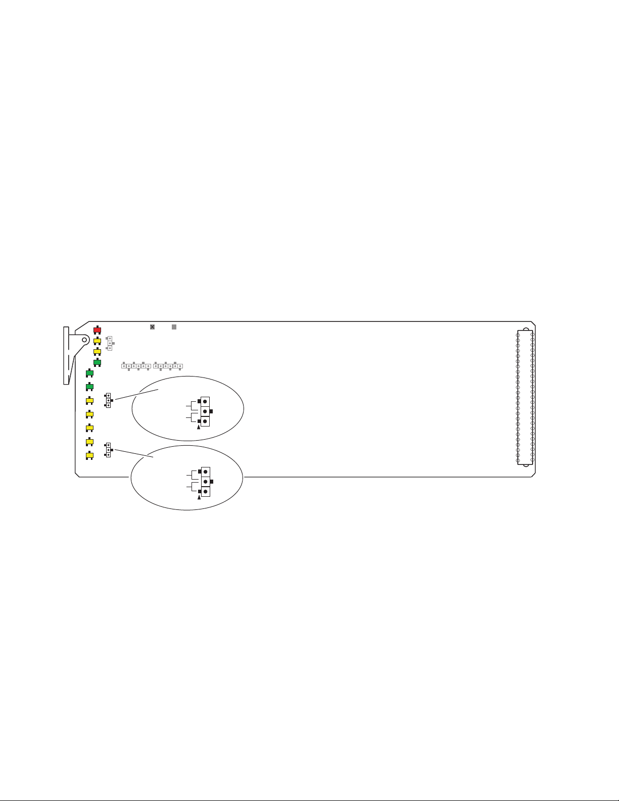
Module On-board Jumper Settings
8937 Module
Two on-board jumpers must be set on the 8937 module to determine
module formatting before installing it in the frame. Refer to Figure 3 for
jumper locations on the module circuit board.
•DA 1 Bypass – set jumper J6 for AUTO (pins 1-2) to enable auto
• Local/Remote – set jumper J7 to LOCAL (pins 1-2) to lock out remote
reclocking (for signal data rates of 143, 177, 270, and 360 Mb/s) or
BYPASS (pins 2-3) to bypass reclocking (for signals with data rates of
4 Mb/s to 360 Mb/s). This setting can be overridden by remote controls.
control or LOCAL & REMOTE (pins 2-3) for access to remote control.
This setting cannot be overridden by remote controls.
Figure 3. On-Board Jumper Locations
FAULT COMM CONF PWR
GRASS VALLEY 8937D SDI RECLOCKING EQ SNMP DA
SIG
PRES
BYPASS 143Mb 177Mb 260Mb 360Mb REM
OVR
8937
BYPASS
BYPASS (2-3)
AUTO (1-2)
J6
LOCAL/REMOTE
REMOTE (2-3)
LOCAL (1-2)
J7
8270_06
10 8937/8937D Instruction Manual
Page 11

8937D Module
Three on-board jumpers must be set on the 8937D module to determine
module formatting before installing it in the frame. Refer to Figure 4 for
jumper locations on the module circuit board.
•DA 1 BYPASS/AUTO – for DA 1, set jumper J6 for AUTO (pins 1-2) to
enable auto reclocking (for signal data rates of 143, 177, 270, and
360 Mb/s) or BYPASS (pins 2-3) to bypass reclocking (for signals with
data rates of 4 Mb/s to 360 Mb/s). This setting can be overridden by
remote controls.
•DA 2 BYPASS/AUTO – for DA 2, set jumper J5 for AUTO (pins 1-2) to
enable auto reclocking (for signal data rates of 143, 177, 270, and
360 Mb/s) or BYPASS (pins 2-3) to bypass reclocking (for signals with
data rates of 4 Mb/s to 360 Mb/s). This setting can be overridden by
remote controls.
• Local/Remote – set jumper J7 to LOCAL (pins 1-2) to lock out remote
control or LOCAL & REMOTE (pins 2-3) for access to remote control.
This setting cannot be overridden by remote controls.
Installation
Figure 4. 8937D On-Board Jumper Locations
FAULT COMM CONF PWR
GRASS VALLEY 8937D SDI RECLOCKING EQ SNMP DA
DA 1
DA 2
SIG
PRES
SIG
PRES
BYPASS 143Mb 177Mb 270Mb 360Mb REM
BYPASS 143Mb 177Mb 270Mb 360Mb REM
OVR
OVR
8937
DA 1
BYPASS (2-3)
AUTO (1-2)
BYPASS (2-3)
AUTO (1-2)
LOCAL/REMOTE
REMOTE (2-3)
LOCAL (1-2)
J7
Looping Capabilities
The reclocked output signal from one 8937 or 8937D module may be looped
to up to ten reclocked 8937 or 8937D modules in series for further distribution without degrading the signal.
J6
DA 2
J5
8270_06
The output signal from modules operating in Bypass mode (not reclocked
to one of the standard rates) will begin to degrade by the third module in
the series. This looping is not recommended.
8937/8937D Instruction Manual 11
Page 12
Installation
Cabling
8937 Module
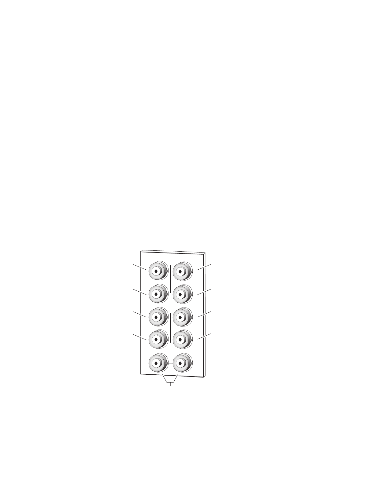
Refer to Figure 5 for cabling the 8937 module. Cabling to and from the
module is done at the back of the Gecko 8900 video frame as described
below.
Note
At the back of every manual are two sets of printed overlay cards that can be
placed over the rear connector BNCs to identify the specific connector functions.
Loop-Through Input
One serial digital component input is provided at differential loop-through
BNCs J9 and J10. If the unused input is not looped to another device, it
should be terminated in 75
Ω
.
Outputs
There are eight outputs for the 8937 module at BNCs J1 through J8. Output
destination equipment should have an input impedance of 75
has loop-through inputs, in which case the loop-through inputs must be
terminated into 75
Figure 5. 8937 Rear Input/Output Connectors
SDI Out 1
SDI Out 3
Ω . All outputs are in phase with the input signal.
SDI Out 2
J2
J2J1
SDI Out 4
Ω unless it
J4
J6
J8
J4
SDI Out 6
J6
SDI Out 8
J8
8270_03
SDI Out 5
SDI Out 7
J3
J5
J7
J9 J10
Differential
loop-through
SDI video inputs
12 8937/8937D Instruction Manual
Page 13

8737D Module
Refer to Figure 6 for cabling the 8937D module. Cabling to and from the
module is done at the back of the Gecko 8900 video frame as described
below.
Installation
Note
At the back of every manual are two sets of six overlay cards that can be
placed over the rear connector BNCs to identify the specific connector functions.
DA 1 Inputs and Outputs
DA 1 provides one serial digital component input at loop-through BNCs J9
and J10. If the unused input is not looped to another device, it should be
terminated in 75
Ω . The three outputs for DA 1 are from BNCs J6, J7, and
J8. All outputs are in phase with the input signal.
DA 2 Inputs and Outputs
DA 2 provides one terminated serial digital component input at BNC J5.
The four outputs for DA 2 are from BNCs J1, J2, J3, and J4. All outputs are
in phase with the input signal.
Figure 6. 8937D Rear Input/Output Connectors
SDI Out 21
SDI Out 23
J1
J2
J2
SDI Out 22
SDI Out 24
SDI In 2
(terminated)
SDI Out 12
J3
J5
J7
J9
SDI In 1
(differential loop-through)
J4
J6
J8
J4
J6
J8
J10
SDI Out 11
SDI Out 13
8270_09
8937/8937D Instruction Manual 13
Page 14

Power Up
Power Up
The front LED indicators and configuration switches are illustrated for the
8937 in Figure 7. The 8937D module has an addition row of identical LEDs
labeled for DA 1 and DA 2. Upon power-up, the green PWR LED should
light and the yellow CONF LED should illuminate for a few seconds for the
duration of module initialization.
Figure 7. LEDs and Configuration Switches
GRASS VALLEY 8937D SDI RECLOCKING EQ SNMP DA
FAULT (red)
COMM (yellow)
CONF (yellow)
PWR (green)
SIG PRES
BYPASS
143Mb
177Mb
270Mb
360Mb
REM OVR
8937
8270_05
Operation Indicator LEDs
Refer to Figure 7 and Table 2 for the name and meaning of each of the board
edge operating indicators on the module circuit board.
Table 2. Board Edge LED Names and Meaning
LED 8937
FAULT
(red)
COMM
(yellow)
CONF
(yellow)
PWR
(green)
On continuously On On Module has detected an internal fault. (Refer to Functional Description on page 30.)
Long Flash Long Flash Long Flash Input missing or input does not match bit rate set with manual mode.
3 Quick Pulses
Short flash Short flash Short flash Activity present on the frame communication bus.
On continuously On On Module is initializing, changing operating modes or programming hardware.
Off Off Off Normal operation.
Off Off Off No activity on frame communication bus.
Off Off Off Module is in normal operating mode.
Off Off Off No power to module or module’s DC/DC converter failed.
On On On Normal operation, module is powered.
DA 1 DA 2
3 Quick
Pulses
8937D
3 Quick
Pulses
Condition
Locate Module command received by the module from a remote control system.
14 8937/8937D Instruction Manual
Page 15

Table 2. Board Edge LED Names and Meaning
Power Up
LED 8937
SIG PRES
(green)
BYPASS
(yellow)
143 Mb
(yellow)
177 Mb
(yellow)
270 Mb
(yellow)
360 Mb
(yellow)
REM OVR
(yellow)
8937D
DA 1 DA 2
Off Off Off
On On On
Off Off Off Reclocking is enabled and auto-rate detection mode is active.
On On On Bypass mode is on, input signal will not be reclocked
Off Off Off No 143 Mb speed signal present.
On On On Input signal is locked at 143 Mb
Off Off Off No 177 Mb speed signal present.
On On On Input signal is locked at 177 Mb
Off Off Off No 270 Mb speed signal present.
On On On Input signal is locked at 270 Mb
Off Off Off No 360 Mb speed signal present.
On On On Input signal is locked at 360 Mb
Off Off Off Module setting match those set on module switches and jumpers.
On On On Remote control is overriding on-board jumper setting
No signal input detected or input signal does not match bit rate set with manual
mode.
In Auto or Bypass mode input signal is present or input signal matches bit rate set
with manual mode.
Condition
Table 3 provides the various output conditions possible for a given input
and module setting.
Table 3. Possible Output Conditions
Input Setting Output Condition
Standard definition SDI video Auto or Bypass Standard definition SDI video
Other carrier Bypass Other carrier
Other carrier Auto Signal with errors
No signal or over EQ range All modes Muted
8937/8937D Instruction Manual 15
Page 16

Configuration
Configuration
Remote Control and Monitoring
The 8937 and 8937D can be controlled and monitored remotely using the
8900NET network interface GUI or a networked control panel. Operation
of these control types is explained in detail in their respective sections of
this manual.
Refer to the following sections for configuration instructions:
•Remote Monitoring (page 16)
•Control Panel Monitoring (page 28)
Module monitoring can be performed using a web browser GUI interface
when the 8900NET Network Interface module is present in the frame
(Gecko 8900TFN-V frame). This section describes the GUI access to the
module functions.
For remote access, make sure the jumper block on the module is set for both
Local and Remote access (Figure 7 on page 14).
Refer to the
mation on the 8900NET Network Interface module and setting up and
operating the Gecko 8900 frame network.
Note
Refer to the Gecko 8900 Frame Status page shown in Figure 8 on page 17.
The 8900 modules can be addressed by clicking either on a specific module
icon in the frame status display or on a module name or slot number in the
link list on the left.
Note
Use the
ware version 3.2.0 and later).
8900NET Network Interface Module Instruction Manual
For optimal performance and access to the latest features, it is recommended
that the 8900NET module be updated to the latest software release. Check the
Grass Valley web site for the current 8900NET software.
The physical appearance of the menu displays on the web pages shown in
this manual represent the use of a particular platform, browser and version
of 8900NET module software. They are provided for reference only. Displays
will differ depending on the type of platform and browser you are using and
the version of the 8900NET software installed in your system.
Refresh
button to update the display (available with 8900NET soft-
for infor-
The
Online Manual Link
pdf format. Link configuration is done on the Frame Configuration page as
described in the
For information on status and fault monitoring and reporting shown on the
Status page, refer to
16 8937/8937D Instruction Manual
button can be set up to link to the documentation in
8900NET Instructions Manual
Status Monitoring
on page 32.
.
Page 17

Figure 8. Gecko 8900 Frame Status Page
8270_04
The Links section lists the frame and its current modules. The selected link's Status
page is first displayed and the sub-list of links for the selection is opened. The sub-list
allows you to select a particular information page for the selected device.
Content display section displays the information page
for the selected frame or module (frame slot icons are also
active links).
Online Manual Link
Refresh button for manual
update of page
Configuration
8937/8937D Instruction Manual 17
Page 18

Configuration
8937 and 8937D Links and Web Pages
The 8900 GUI provides the following links and web pages for the 8937 and
8937D modules (Figure 9):
• Status – reports input signal and frame bus communication status and
module information (page 19),
• Standard Selections –allows enabling and disabling of signal loss
reporting and selection of the standard selection mode (page 20),
•Recall Factory Defaults – provides factory default recall (page 24),
• Slot Config – provides a Locate Module function and Slot Memory
(page 25), and
• Software Update – describes software updating procedure (page 27).
Figure 9. 8937 and 8937D Web Page Links
18 8937/8937D Instruction Manual
Page 19

Status Web Page
Configuration
Use
this
link
The Status web page (Figure 10) shows the signal status of the input signal
and communication with the frame bus. Color coding of the display indicates the signal status. Refer to Status Monitoring on page 32 for an explanation of the color coding.
Information about the module, such as part number, serial number, hardware revision and software versions are given in a Properties section at the
bottom of the display.
All web page displays for either the 8937 or 8937D module will show the
model as 8937(D). To identify which module is installed, refer to the Hardware Revision or the Part Number field in the Properties section of the
Status web page. 8937 modules are noted as a -00 while 8937D modules are
noted as -10 (8937D shown in Figure 10).
Figure 10. 8937 and 8937D Status Web Page
Dash version indicates
module type
8937/8937D Instruction Manual 19
Page 20

Configuration
Use
this
link
Standard Selections Web Page
The Standard Selections web page allows you to set loss of signal reporting
and opeerating mode for the 8937 and 8937D modules. Refer to the specific
8937 or 8937D heading below.
8937 Module
Refer to Figure 11 for the Standard Selections web page for the 8937.
• Set the Report Loss of Signal input presence reporting to
abling this control will gray out the Input signal on the Status web page
graphic shown in Figure 10 on page 19.
• The Input Signal field will report the status of the input signal.
• Set the Mode control to
module),
(input bypasses reclocking circuitry).
•When Auto or Bypass mode is selected, the currently detected bit rate
detected by the module will be displayed in the Current Bit Rate field.
Click the
Figure 11. 8937 Standards Selections Web Page
Manual (input bit rate standard selected manually), or Bypass
Apply button to enter any values.
Auto (input bit rate standard detected by
Yes or No. Dis-
20 8937/8937D Instruction Manual
Page 21

Configuration
When Manual mode is selected, a Standard Selection pulldown will appear
as shown in Figure 12.
Select a bit rate from the Standard Selection pulldown from one of the following:
•
143 Mb,
•
177 Mb,
•
270 Mb, or
•
360 Mb
The currently selected manual rate will be shown next to the pulldown.
Figure 12. 8937 Operating Mode Set to Manual
8937/8937D Instruction Manual 21
Page 22

Configuration
8937D Module
The Standards Selections page for the 8937D (Figure 13 on page 23) provides a common reporting of signal loss control for both DAs and two sets
of separate controls for standard selection.
Click the
• The Report Loss of Signal control is common to both DAs. A loss of
For DA 1:
• Set the Mode control for DA 1 to
• The Input Signal field will report the status of the DA 1 input signal.
•When Auto or Bypass mode is selected, the currently detected bit rate
•When
Apply button to enter all values.
signal will be reported if either one or both DAs lose the input signal.
Set the input presence reporting to
Disabling this control will gray out the corresponding Input signal on
the Status web page graphic shown in Figure 10 on page 19.
by module),
Bypass (input bypasses reclocking circuitry).
detected by the module will be displayed in the Current Bit Rate field.
Manual mode is selected, a Standard Selection pulldown will
appear similar to the one shown in the DA 2 illustration in Figure 13 on
page 23. Select the bit rate from the Standard Selection pulldown
(
143 Mb, 177 Mb, 270 Mb, or 360 Mb) as desired. The currently selected
manual rate will be shown next to the pulldown.
Manual (input bit rate standard selected manually), or
Yes or No for both DA 1 and DA 2.
Auto (input bit rate standard detected
For DA 2:
• Set the Mode 2 control for DA 2 to
by module),
Bypass (input bypasses reclocking circuitry).
• The Input Signal 2 field will report the status of the DA 2 input signal.
•When Auto or Bypass mode is selected, the currently detected bit rate
detected by the module will be displayed in the Current Bit Rate 2 field.
•When
appear similar to the one shown in Figure 13 on page 23. Select the bit
rate from the Standard Selection 2 pulldown (
360 Mb) as desired. The currently selected manual rate will be shown
next to the pulldown.
Manual mode is selected, a Standard Selection 2 pulldown will
Manual (input bit rate standard selected manually), or
Auto (input bit rate standard detected
143 Mb, 177 Mb, 270 Mb, or
22 8937/8937D Instruction Manual
Page 23

Figure 13. 8937D Standard Selection Web Page
Configuration
8937/8937D Instruction Manual 23
Page 24

Configuration
Use
this
link
Recall Factory Defaults Web Page
Use the Recall Factory Defaults web page (Figure 14) to recall preset factory
defaults of:
•Report Loss of Signal =
•Mode Control =
Note For the 8937D module, this will recall factory defaults for both DAs.
Figure 14. 8937 and 8937D Recall Factory Defaults Web Page
Auto.
Yes, and
24 8937/8937D Instruction Manual
Page 25

Use
this
link
Slot Config Web Page
Use the Slot Config web page (Figure 15 on page 26) to perform the following functions on the module:
•
Locate Module – selecting the Flash radio button flashes the yellow
COMM LED on the front of the module so it can be located in the frame.
•
Slot Identification – You may identify the module by typing a specific
name in the
module and travels with the 8900NET module if it is moved to another
frame. Select
•
Slot Memory – the slot configuration for each media module is automati-
cally saved periodically (once an hour) to the 8900NET module in that
frame. You may also select the
save the current configuration for this slot. The configuration is saved
on the 8900NET module. If the 8900NET module is removed or
powered down, the stored configurations are not saved.
Configuration
Name field. The assigned name is stored on the 8900NET
Default to enter the factory default module name.
Learn Module Config button at any time to
When the
ration saved to this slot is saved as slot memory. When the current
module is removed and another module of the same type is installed,
the configuration saved to the 8900NET module will be downloaded to
the new module. The box must be checked before the current module
with the saved configuration is removed.
•
Hardware Switch Controls – a read-only status report of 8900NET module
switch settings for Module Status Reporting and Asynchronous Status
Reporting. These functions must be enabled for the following Slot
SNMP Trap Reports to function.
•
Slot SNMP Trap Reports – displayed only when the SNMP Agent software
has been installed on the 8900NET module. Slot SNMP traps can be
enabled only when the hardware switches for Module Fault reporting
and Asynchronous Status reporting are enabled on the 8900NET
module (dipswitch S1 segment 7 and dipswitch S2 segment 1).
The enabled SNMP traps will be reported to any SNMP manager that
is identified as an SNMP Report Destination in 8900NET configuration.
Trap severity is read-only hard-coded information that is interpreted
and responded to by the SNMP Manager software configuration.
SNMP reporting can be also be disabled for the signal input(s) on the
Standard Selections web page.
Restore upon Install box has been checked, the current configu-
8937/8937D Instruction Manual 25
Page 26

Configuration
Figure 15. 8937 and 8937D Slot Config Page
26 8937/8937D Instruction Manual
Page 27

Use
this
link
Configuration
Software Update Web Page
The Software Update web page (Figure 16) indicates that module software
updates via the web or using the NetConfig networking application are not
supported.
Refer to the release notes for the latest software upgrade for instructions on
updating 8937 software.
Figure 16. 8937 and 8937D Software Update Web Page
8937/8937D Instruction Manual 27
Page 28

Configuration
Newton Control Panel Configuration
The Newton control panel is available to interface over the network to the
8937 and 8937D modules. The configuration functions available with the
Grass Valley Newton Control System are shown in the Newton Control
Panel Configurator illustration in Figure 17.
Note Available parameters will depend on the module type installed. This example
reflects the 8937D module.
Figure 17. Newton Configurator Control Panel Parameters
8937D only
Installation, configuration, and operation of the Newton Modular Control
System is provided in a separate manual provided with the control panel
option.
28 8937/8937D Instruction Manual
Page 29

Specifications
Specifications
Table 4. 8937 and 8937D Specifications
Parameter Value
Serial Digital Component Inputs
Number of inputs 8937: 2 BNC differential loop-through
Input impedance High Z
Signal type Serial digital SMPTE 259M (143 Mb/s, 177 Mb/s, 270 Mb/s, 360 Mb/s),
Reclocked data rates 143 Mb/s, 177 Mb/s, 270 Mb/s, and 360 Mb/s
Supported data rates 4 Mb/s to 360 Mb/s
Signal level SDI 800 mV p-p (± 10% maximum)
Return loss > 15 dB 4 MHz to 360 MHz
Automatic cable equalization
(Belden 8281 cable)
Serial Digital Component Outputs
Number of outputs 8937: 8 BNCs
Output impedance 75 Ω
Signal types Serial digital SMPTE 259M (143 Mb/s, 177 Mb/s, 270 Mb/s, 360 Mb/s),
Signal level SDI 800 mV p-p (± 10% maximum)
Return loss > 15 dB 4 MHz to 360 MHz
Error checking Transparent to embedded EDH
Electrical length < 20 ns
Output polarity Non-inverted
Rise and fall time 400 – 700 ps
Jitter < 0.2 UI
Environmental
Frame temperature range Refer to frame specification
Operating humidity range 10 to 90% non-condensing
Non-operating temperature –10 to + 70 degrees C
Mechanical
Frame type Gecko 8900 Video/8800/8500 (with trace cut),
Power
Power consumption < 3 W
8937D: DA 1 – 2 BNC loop-through
8937D: DA 2 – 1 terminated BNC
SMPTE 310M,
DVB-ASI
< 300 meters up to 270 Mb/s
< 200 meters up to 360 Mb/s
8937D: DA 1 – 3 BNCs
8937D: DA 2 – 4 BNCs
SMPTE 310M,
DVB-ASI
8937/8937D Instruction Manual 29
Page 30

Functional Description
Functional Description
Input and Output Processing
The input section(s) receive SD (standard definition) video from the rear
input BNCs and send it to signal equalizing and reclocking circuits. The
input section can also bypass reclocking circuits to the output amplifiers.
The output amplifiers drive eight equal-phase outputs on the rear backplane for the 8937 and one set of four outputs and one set of three outputs
for the 8937D.
Note All outputs are in phase with the input signal.
Microprocessor and Input Selector
The primary purpose of the microprocessor is to provide remote control
and monitoring capability for the module. It receives signal present, signal
lock, and speed detection signals from the equalizer and reclocker circuits.
Using this information, local jumper settings, and remote control commands, the microprocessor selects the internal signal path and gives feedback through the LEDs and remote control bus.
User-enabled video presence detection generates individual SNMP traps
for each channel that can be sent to an SNMP manager via the microprocessor.
30 8937/8937D Instruction Manual
Page 31

Service
Service
The 8937 and 8937D modules make extensive use of surface-mount technology and programmed parts to achieve compact size and adherence to
demanding technical specifications. Circuit modules should not be serviced in the field unless directed otherwise by Customer Service.
If your module is not operating correctly, proceed as follows:
•Check frame and module power and signal present LEDs.
•Verify power at the voltage testpoints (see Figure 18) and check fuse if
no voltage is detected.
•Check for presence and quality of input signals.
•Verify that source equipment is operating correctly.
•Check cable connections.
Refer to Figure 7 for the location of PWR LED and Table 2 on page 14 for
proper LED indications.
If the module is still not operating correctly, replace it with a known good
spare and return the faulty module to a designated Grass Valley repair
depot. Call your Grass Valley representative for depot location.
Refer to the Contacting Grass Valley at the front of this document for the
Grass Valley Customer Service Information number.
Figure 18. 8937 and 8937D Fuse and Voltage Testpoint Locations
FAULT COMM CONF PWR
GRASS VALLEY 8937D SDI RECLOCKING EQ SNMP DA
SIG
PRES
BYPASS 143Mb 177Mb 260Mb 360Mb REM
OVR
8937
Voltage
Test Points
+5V
2
GND
J8
Fuse
2AMP
125V
FAST
F1
8270_08
8937/8937D Instruction Manual 31
Page 32

Status Monitoring
Status Monitoring
This section provides a summary of status monitoring and reporting for a
Gecko 8900 Series system. It also summarizes what status items are
reported and how to enable/disable reporting of each item. There are a
number of ways to monitor status of modules, power supplies, fans and
other status items depending on the method of monitoring being used.
8900 Frame status will report the following items:
• Power supply health,
• Status of fans in the frame front cover,
•Temperature,
•Module health, and
• Frame bus status.
Module health status will report the following items:
• Internal module state (and state of submodule or options enabled)
including configuration errors (warning), internal faults, and normal
operation (Pass).
LEDs
• Signal input states including valid/present (pass), not present or
invalid (warning), not monitored (unknown), and not available (no
signal inputs).
•Reference input states including locked/valid (pass), not
locked/invalid (warning), and not monitored (unknown).
• Signal output states with reporting functionality (reference output).
LEDs on modules in the frame and on the front of the 8900TF/TFN frames
indicate status of the frame and the installed power supplies, fans in the
front covers, and modules.
When a red FAULT LED is lit on a frame front cover, the fault will also be
reported on the 8900NET or Frame Monitor module. The LEDs on the front
of these modules can then be read to determine the following fault conditions:
• Power Supply 1 and 2 health,
• Fan rotation status,
• Frame over-temperature condition,
• Frame Bus fault (8900NET only), and
•Module health bus.
32 8937/8937D Instruction Manual
Page 33

Frame Alarm
Status Monitoring
In general, LED colors used on the frame and modules indicate:
•Green = normal operation, (Pass) or signal present, module locked.
•Red – On continuously = fault condition, flashing = configuration error.
•Yellow – On continuously = active condition (configuration mode or
communication), flashing in sequence = module locator function.
Status LEDs for this module are described in Operation Indicator LEDs on
page 14. LEDs for the 8900NET module are described in the 8900NET
Network Interface Instruction Manual.
A Frame Alarm connection is available on pins 8 and 9 of the RS-232 connector on the rear of the 8900 frame (Frame Monitor or 8900NET Network
Interface module required). This will report any of the status items enabled
with the 8900NET or Frame Monitor module configuration DIP switch.
Connection and use of the Frame Alarm is covered in detail in the 8900NET
Network Interface Instruction Manual.
Web Browser Interface
When the 8900NET module is installed in the frame, a web browser GUI
can indicate frame and module status on the following web pages:
• Frame Status page – reports overall frame and module status in graph-
ical and text formats.
•Module Status page – shows specific input and reference signal status
to the module along with enabled options and module versions.
•A Status LED icon on each web page to report communication status
for the frame slot and acts as a link to the Status page where warnings
and faults are displayed (8900NET version 3.0 or later).
In general, graphics and text colors used indicate the following:
•Green = Pass – signal or reference present, no problems detected.
•Red = Fault – fault condition.
•Yellow = Warning – signal is absent, has errors, or is mis-configured.
•Gray = Not monitored (older 8900 module).
•White = Not present.
Status reporting for the frame is enabled or disabled with the configuration
DIP switches on the 8900NET module. Most module status reporting items
can be enabled or disabled on individual configuration web pages.
8937/8937D Instruction Manual 33
Page 34

Status Monitoring
SNMP Reporting
The Gecko 8900 Series system uses the Simple Network Monitoring Protocol (SNMP) internet standard for reporting status information to remote
monitoring stations. When SNMP Agent software is installed on the
8900NET module, enabled status reports are sent to an SNMP Manager
such as the Grass Valley’s NetCentral application.
There are both hardware and software report enable switches for each
report. Both must be enabled for the report to be sent. Software report
switches are set on the 8900NET Configuration page for the Frame, the
8900NET module, and each module slot. Refer to the 8900NET Network
Interface Instruction Manual for installation instructions.
34 8937/8937D Instruction Manual
Page 35

Index
Numerics
8900 frame
frame alarm
module capacity 8
status reporting 32
8900NET module
installation
8937 module
features
8937D module
features
B
33
8
7
7
14
states
troubleshooting 32
Frame Controller module 8
Frame Status page 33
frequently asked questions 2
functional description 30
fuse 31
G
Gecko frame 8, 29
graphical user interface (GUI) 18
Grass Valley web site 2
backplane 9
C
cabling
8937
12
8937D 13
COMM LED 14
CONF LED 14
configuration
Remote, GUI
connectors 9
controller module 8
D
documentation online 2, 16
E
enable SNMP 34
environmental 29
16
I
identifying module type 19
inputs
specification
installation 8
29
J
jumpers, on-board
8937
10
8937D 11
L
LEDs
front edge
Names and Meanings table 14
locate module 25
looping modules 11
14
M
manual mode
F
FAQ database 2
FAULT LED
8937/8937D Instruction Manual 35
8937
8937D 22
module
21
Page 36

Index
controller 8
installation 8
power supply 8
slots 9
module health status 32
Module Status web page 33
N
Newton Control Panel
configuration
overview 28
28
O
online documentation 2
Online Manual Link 16
Online Manual Link 16
outputs
specification
overlay 12, 13
29
P
power 29
power supply 8
power up 14
PWR LED 14
Software Update web page 27
specifications 29
Standard Selections web page
8937
20
8937D 22
status monitoring 32
Status web page 19
T
testpoints 31
TRK ON LED 15
troubleshooting 31
V
voltage tespoints 31
W
web site documentation 2
web site FAQ database 2
web site Grass Valley 2
web site software download 2
R
rear connectors 9
Recall Factory Defaults web page 24
Refresh button 16
REM OVR LED 15
repair depot 31
report enable switches 34
S
Slot Config web page 25
slot memory 25
SNMP reporting
enabling
overview 34
software download from web 2
36 8937/8937D Instruction Manual
25
Page 37

8937 SDI Reclocking EQ SNMP DA Module
Rear Connector Overlay
Fold along vertical lines to break perforations, then tear to separate vertical pairs.
Fold FoldFold FoldFold Fold
Out 1
J1
Out 3
J3
Out 5
J5
Out 7
J7
J9
Out 1
8937
SDI In
8937
Out 2
Out 4
Out 6
Out 8
J10
Out 2
J6
J8
J2
J4
Out 1
J1
Out 3
J3
Out 5
J5
Out 7
J7
J9
Out 1
8937
SDI In
8937
Out 2
Out 4
Out 6
Out 8
J10
Out 2
J2
J4
J6
J8
J1
J3
J5
J7
J9
Out 1
Out 3
Out 5
Out 7
Out 1
8937
SDI In
8937
Out 2
Out 4
Out 6
Out 8
J10
Out 2
J2
J4
J6
J8
J1
J3
J5
J7
J9
Out 3
Out 5
Out 7
SDI In
Out 4
Out 6
Out 8
J10
J6
J8
J2
J4
J1
Out 3
J3
Out 5
J5
Out 7
J7
J9
SDI In
Out 4
Out 6
Out 8
J10
J4
J6
J8
J2
J1
J3
J5
J7
J9
Out 3
Out 5
Out 7
J2
Out 4
J4
Out 6
J6
Out 8
J8
SDI In
J10
Fold FoldFold FoldFold Fold
Page 38

18 8937/8937D Instruction Manual
Page 39

8937D Dual SDI Reclocking SNMP EQ DA Module
Rear Connector Overlay
Fold along vertical lines to break perforations, then tear to separate vertical pairs.
Fold FoldFold FoldFold Fold
Out 21
J1
Out 23
J3
SDI In 2
J5
Out 12
J7
J9
Out 21
8937D
SDI In 1
8937D
Out 22
Out 24
Out 11
Out 13
J10
Out 22
J6
J8
J2
J4
Out 21
J1
Out 23
J3
SDI In 2
J5
Out 12
J7
J9
Out 21
8937D
SDI In 1
8937D
Out 22
Out 24
Out 11
Out 13
J10
Out 22
J2
J4
J6
J8
Out 21
J1
Out 23
J3
SDI In 2
J5
Out 12
J7
J9
Out 21
8937D
SDI In 1
8937D
Out 22
J2
Out 24
J4
Out 11
J6
Out 13
J8
J10
Out 22
J1
Out 23
J3
SDI In 2
J5
Out 12
J7
J9
SDI In 1
Out 24
Out 11
Out 13
J10
J6
J8
J2
J4
J1
Out 23
J3
SDI In 2
J5
Out 12
J7
J9
SDI In 1
Out 24
Out 11
Out 13
J10
J4
J6
J8
J2
J1
Out 23
J3
SDI In 2
J5
Out 12
J7
J9
J2
Out 24
J4
Out 11
J6
Out 13
J8
SDI In 1
J10
Fold FoldFold FoldFold Fold
Page 40

18 8937/8937D Instruction Manual
 Loading...