

Page 1

8937/8937D
SDI/ASI RECLOCKING EQ SNMP DA MODULES
Instruction Manual
SOFTWARE VERSION 1.1.0
071827003
NOVEMBER 2008
Page 2

Affiliate with the N.V. KEMA in The Netherlands
CERTIFICATE
Certificate Number: 510040.001
The Quality System of:
Grass Valley, Inc.
400 Providence Mine Road
Nevada City, CA 95945
United States
15655 SW Greystone Ct.
Beaverton, OR 97006
United States
10 Presidential Way
3
rd
Floor, Suite 300
Woburn, MA 01801
United States
Nederland B.V.
4800 RP BREDA
The Netherlands
Weiterstadt, Germany
Brunnenweg 9
D-64331 Weiterstadt
Germany
Rennes, France
Rue du Clos Courtel
Cesson-Sevigne, Cedex
France
Technopole Brest Iroise
CS 73808
29238 Brest Cedex 3
France
17 rue du Petit Albi-BP 8244
95801 Cergy Pontoise
Cergy, France
2300 South Decker Lake Blvd.
Salt Lake City, UT 84119
United States
7140 Baymeadows Way
Suite 101
Jacksonville, FL 32256
United States
Including its implementation, meets the requirements of the standard:
ISO 9001:2000
Scope:
The design, manufacture and support of video hardware and software products and
related systems.
This Certificate is valid until: June 14, 2009
This Certificate is valid as of: August 30, 2006
Certified for the first time: June 14, 2000
H. Pierre Sallé
President
KEMA-Registered Quality
The method of operation for quality certification is defined in the KEMA General Terms
And Conditions For Quality And Environmental Management Systems Certifications.
Integral publication of this certificate is allowed.
KEMA-Registered Quality, Inc.
4377 County Line Road
Chalfont, PA 18914
Ph: (215)997-4519
Fax: (215)997-3809
CRT 001 073004
ccredited By:
ANAB
A
Page 3
8937/8937D
SDI/ASI RECLOCKING EQ SNMP DA MODULES
Instruction Manual
SOFTWARE VERSION 1.1.0
071827003
NOVEMBER 2008
Page 4

Contacting Grass Valley
International
Support Centers
Local Support
Centers
(available
during normal
business hours)
France
24 x 7
Australia and New Zealand: +61 1300 721 495 Central/South America: +55 11 5509 3443
Middle East: +971 4 299 64 40 Near East and Africa: +800 8080 2020 or +33 1 48 25 20 20
Europe
+800 8080 2020 or +33 1 48 25 20 20
+800 8080 2020 or +33 1 48 25 20 20
Hong Kong, Taiwan, Korea, Macau: +852 2531 3058 Indian Subcontinent: +91 22 24933476
Asia
Southeast Asia/Malaysia: +603 7805 3884 Southeast Asia/Singapore: +65 6379 1313
China: +861 0660 159 450 Japan: +81 3 5484 6868
Belarus, Russia, Tadzikistan, Ukraine, Uzbekistan: +7 095 2580924 225 Switzerland: +41 1 487 80 02
S. Europe/Italy-Roma: +39 06 87 20 35 28 -Milan: +39 02 48 41 46 58 S. Europe/Spain: +34 91 512 03 50
Benelux/Belgium: +32 (0) 2 334 90 30 Benelux/Netherlands: +31 (0) 35 62 38 42 1 N. Europe: +45 45 96 88 70
Germany, Austria, Eastern Europe: +49 6150 104 444 UK, Ireland, Israel: +44 118 923 0499
Copyright © Thomson. All rights reserved.
This product may be covered by one or more U.S. and foreign patents.
United States/Canada
24 x 7
+1 800 547 8949 or +1 530 478 4148
Grass Valley Web Site
The www.thomsongrassvalley.com web site offers the following:
Online User Documentation — Current versions of product catalogs, brochures,
data sheets, ordering guides, planning guides, manuals, and release notes
in .pdf format can be downloaded.
FAQ Database — Solutions to problems and troubleshooting efforts can be
found by searching our Frequently Asked Questions (FAQ) database.
Software Downloads — Download software updates, drivers, and patches.
4 8937/8937D — Instruction Manual
Page 5

Contents
Preface. . . . . . . . . . . . . . . . . . . . . . . . . . . . . . . . . . . . . . . . . . . . . . . . . . . . . . . . . . . . . . . . . . . . . 7
8937 and 8937D SDI/ASI Reclocking EQ SNMP DAs . . . . . . . . . . . . . . . . . . . 9
About This Manual . . . . . . . . . . . . . . . . . . . . . . . . . . . . . . . . . . . . . . . . . . . . . . . . . . . . . 7
Introduction . . . . . . . . . . . . . . . . . . . . . . . . . . . . . . . . . . . . . . . . . . . . . . . . . . . . . . . . . . . 9
Installation . . . . . . . . . . . . . . . . . . . . . . . . . . . . . . . . . . . . . . . . . . . . . . . . . . . . . . . . . . . 10
Gecko 8900 Frame . . . . . . . . . . . . . . . . . . . . . . . . . . . . . . . . . . . . . . . . . . . . . . . . . . . 10
Frame Capacity. . . . . . . . . . . . . . . . . . . . . . . . . . . . . . . . . . . . . . . . . . . . . . . . . . . . 10
Module Placement in the 8900 Frame. . . . . . . . . . . . . . . . . . . . . . . . . . . . . . . . . . . 10
GeckoFlex Frame . . . . . . . . . . . . . . . . . . . . . . . . . . . . . . . . . . . . . . . . . . . . . . . . . . . . 12
Module Installation Precautions . . . . . . . . . . . . . . . . . . . . . . . . . . . . . . . . . . . . . 12
Rear Module Installation . . . . . . . . . . . . . . . . . . . . . . . . . . . . . . . . . . . . . . . . . . . 13
Front Module Installation. . . . . . . . . . . . . . . . . . . . . . . . . . . . . . . . . . . . . . . . . . . 14
Cabling . . . . . . . . . . . . . . . . . . . . . . . . . . . . . . . . . . . . . . . . . . . . . . . . . . . . . . . . . . . . 15
8937 Module . . . . . . . . . . . . . . . . . . . . . . . . . . . . . . . . . . . . . . . . . . . . . . . . . . . . . . 15
8737D Module . . . . . . . . . . . . . . . . . . . . . . . . . . . . . . . . . . . . . . . . . . . . . . . . . . . . 16
Looping Capabilities . . . . . . . . . . . . . . . . . . . . . . . . . . . . . . . . . . . . . . . . . . . . . . . . . 16
Power Up . . . . . . . . . . . . . . . . . . . . . . . . . . . . . . . . . . . . . . . . . . . . . . . . . . . . . . . . . . . . 17
Operation Indicator LEDs . . . . . . . . . . . . . . . . . . . . . . . . . . . . . . . . . . . . . . . . . . . . 18
Configuration. . . . . . . . . . . . . . . . . . . . . . . . . . . . . . . . . . . . . . . . . . . . . . . . . . . . . . . . . 20
Configuration Summary. . . . . . . . . . . . . . . . . . . . . . . . . . . . . . . . . . . . . . . . . . . . . . 21
Local On-Board Configuration . . . . . . . . . . . . . . . . . . . . . . . . . . . . . . . . . . . . . . . . 22
8937 Module . . . . . . . . . . . . . . . . . . . . . . . . . . . . . . . . . . . . . . . . . . . . . . . . . . . . . . 22
8937D Module . . . . . . . . . . . . . . . . . . . . . . . . . . . . . . . . . . . . . . . . . . . . . . . . . . . . 23
Remote Configuration and Monitoring . . . . . . . . . . . . . . . . . . . . . . . . . . . . . . . . . 24
8900NET Module Information . . . . . . . . . . . . . . . . . . . . . . . . . . . . . . . . . . . . . . . 24
Newton Control Panel Configuration. . . . . . . . . . . . . . . . . . . . . . . . . . . . . . . . . 24
Web Browser Interface . . . . . . . . . . . . . . . . . . . . . . . . . . . . . . . . . . . . . . . . . . . . . 25
8937 and 8937D Links and Web Pages . . . . . . . . . . . . . . . . . . . . . . . . . . . . . . . . 27
Status Web Page. . . . . . . . . . . . . . . . . . . . . . . . . . . . . . . . . . . . . . . . . . . . . . . . . . . 28
Standard Selections Web Page. . . . . . . . . . . . . . . . . . . . . . . . . . . . . . . . . . . . . . . 30
Recall Factory Defaults Web Page. . . . . . . . . . . . . . . . . . . . . . . . . . . . . . . . . . . . 34
Slot Config Web Page . . . . . . . . . . . . . . . . . . . . . . . . . . . . . . . . . . . . . . . . . . . . . . 35
Software Updating . . . . . . . . . . . . . . . . . . . . . . . . . . . . . . . . . . . . . . . . . . . . . . . . . . . . 38
Status Monitoring . . . . . . . . . . . . . . . . . . . . . . . . . . . . . . . . . . . . . . . . . . . . . . . . . . . . . 38
External Frame Alarm. . . . . . . . . . . . . . . . . . . . . . . . . . . . . . . . . . . . . . . . . . . . . . . . 39
LED Reporting . . . . . . . . . . . . . . . . . . . . . . . . . . . . . . . . . . . . . . . . . . . . . . . . . . . . . . 39
Web Browser Interface . . . . . . . . . . . . . . . . . . . . . . . . . . . . . . . . . . . . . . . . . . . . . . . 40
SNMP Reporting . . . . . . . . . . . . . . . . . . . . . . . . . . . . . . . . . . . . . . . . . . . . . . . . . . . . 40
Specifications . . . . . . . . . . . . . . . . . . . . . . . . . . . . . . . . . . . . . . . . . . . . . . . . . . . . . . . . . 41
Service. . . . . . . . . . . . . . . . . . . . . . . . . . . . . . . . . . . . . . . . . . . . . . . . . . . . . . . . . . . . . . . 42
Functional Description . . . . . . . . . . . . . . . . . . . . . . . . . . . . . . . . . . . . . . . . . . . . . . . . . 43
Input and Output Processing. . . . . . . . . . . . . . . . . . . . . . . . . . . . . . . . . . . . . . . . . . 43
Microprocessor and Input Selector. . . . . . . . . . . . . . . . . . . . . . . . . . . . . . . . . . . . . 43
8937/8937D — Instruction Manual 5
Page 6

Contents
Index. . . . . . . . . . . . . . . . . . . . . . . . . . . . . . . . . . . . . . . . . . . . . . . . . . . . . . . . . . . . . . . . . . . . . . 45
6 8937/8937D — Instruction Manual
Page 7

Preface
About This Manual
This manual describes the features of the 8937 and 8937D modules in the
GeckoFlex Signal Processing System family. As part of this module family,
it is subject to Safety and Regulatory Compliance described in the Gecko
8900 Frames Instruction Manual and the GeckoFlex Frames 8900FX/FF/FFN
Signal Processing System Instruction Manual.
All Modular product documentation can be found on-line in PDF format at
this link:
www.thomsongrassvalley.com/docs/modular
8937/8937D — Instruction Manual 7
Page 8

Preface
8 8937/8937D — Instruction Manual
Page 9

8937 and 8937D SDI/ASI Reclocking EQ SNMP DAs
Introduction
The 8937 module is a 1 x 8 looping input, auto-reclocking, auto-cable equalizing DA with SNMP monitoring capability. The module is suited for
medium to long distance signal distribution.
The 8937D (dual) module provides two separate SDI distribution amplifiers on a single card. It also has auto-reclocking, auto-cable equalizing with
SNMP monitoring capability for both video channels. The module is ideal
for environments where compact and high density capability is required
such as mobile trucks.
The 8937 and 8937D feature:
• Jumper selectable Bypass/270Mb/Reclock mode with auto bypass,
• Auto detection and front panel indication of all SMPTE 259M signal
data rates,
• Auto, Manual, or Bypass mode for input bit rate standard selection,
• Auto cable equalization for up to 300 meters of cable for SDI SMPTE
signals up to 270 Mb/s and 200 meters for 360 Mb/s,
• Suitable for SMPTE 259M, DVB-ASI, SDI 270 Mb/s and other 800 mV
data ranging from 50 Mb/s to 360 Mb/s with maximum P/N of 19/1,
• Signal presence indication with module specific SNMP trap generation,
and
• Remote health monitoring interface.
This manual covers installation, configuration, and operation for both the
8937 and 8937D modules.
8937/8937D — Instruction Manual 9
Page 10

Installation
Installation
Gecko 8900 Frame
The 8937 and 8937D modules can be installed in either an 8900 Gecko or
GeckoFlex frame. An 8900V-R rear module is required for use in the
GeckoFlex frame.
Installation of an 8937 module in an 8900 Gecko frame is a process of:
1. Placing the module in the proper frame slot,
2. Setting jumper settings if using local configuration controls (see Local
On-Board Configuration on page 22), and
3. Cabling signal ports.
The 8937 module can be plugged in and removed from an 8900 Series Video
frame with power on. When power is applied to the module, LED indicators reflect the initialization process (see Power Up on page 17).
Frame Capacity
The 8937 and 8937D modules can be installed in all Gecko 8900 Series Video
but with varying maximum quantities determined by frame cooling
capacity.
maximum module count for each frame type.
Table 1. Power, Cooling, and Module Capacity of 8900 Video Frames
Power (W) 100 100 100
Recommended Module Cooling (W) 30 100 100
8937 Modules 10 10 10
8937D Modules 10 10 10
Note Module capacity figures assume no other modules are in the frame.
Ta bl e 1 provides the power capacity, cooling capacity, and
Capacity Calculated
8900TX-V
Frame (no fan)
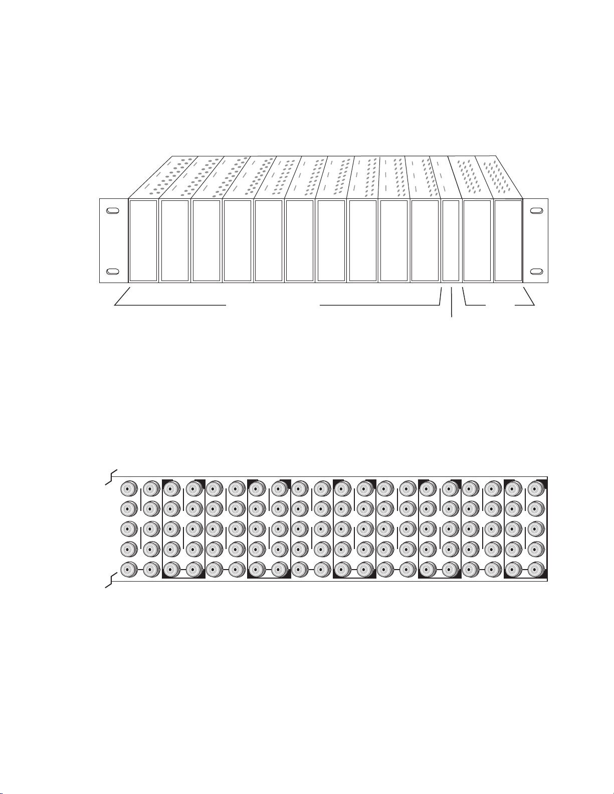
Module Placement in the 8900 Frame
There are ten slot locations in the video frame to accommodate modules.
These are the left ten locations. Refer to
8900TF
Frame
Figure 1 on page 11.
8900TFN
Frame
The two slots on the right are allocated for the power supplies. For additional information concerning the Power Supply module, refer to the 8900
Frames Instruction Manual.
10 8937/8937D — Instruction Manual
Page 11
Installation
Frame Monitor or
8900NET Network
Interface Module
Any Gecko/8900 Module
Power
Supplies
8270_02r1
8270_01
J1 J2
J3 J4
J5 J6
J7 J8
J9 J10
IN
DA1
J2
J4
J6
J8
J1 J2
J3 J4
J5 J6
J7 J8
J9 J10
IN
DA3
J1 J2
J3 J4
J5 J6
J7 J8
J9 J10
IN
DA5
J1 J2
J3 J4
J5 J6
J7 J8
J9 J10
IN
DA2
J1 J2
J3 J4
J5 J6
J7 J8
J9 J10
IN
DA7
J1 J2
J3 J4
J5 J6
J7 J8
J9 J10
IN
DA9
J1 J2
J3 J4
J5 J6
J7 J8
J9 J10
IN
DA4
J2
J4
J6
J8
J1 J2
J3 J4
J5 J6
J7 J8
J9 J10
IN
DA6
J2
J4
J6
J8
J1 J2
J3 J4
J5 J6
J7 J8
J9 J10
IN
DA8
J2
J4
J6
J8
J1 J2
J3 J4
J5 J6
J7 J8
J9 J10
IN
DA10
O
U
T
O
U
T
O
U
T
O
U
T
O
U
T
O
U
T
O
U
T
O
U
T
O
U
T
O
U
T
The third slot from the right is allocated for either a Frame Monitor Module
or a 8900NET (Net Card) Network Interface Module. For additional infor
mation concerning the controller module options, refer to the 8900NET (Net
Card) Network Interface Module Instruction Manual.
Figure 1. 8900 Series Video Frame Slots
-
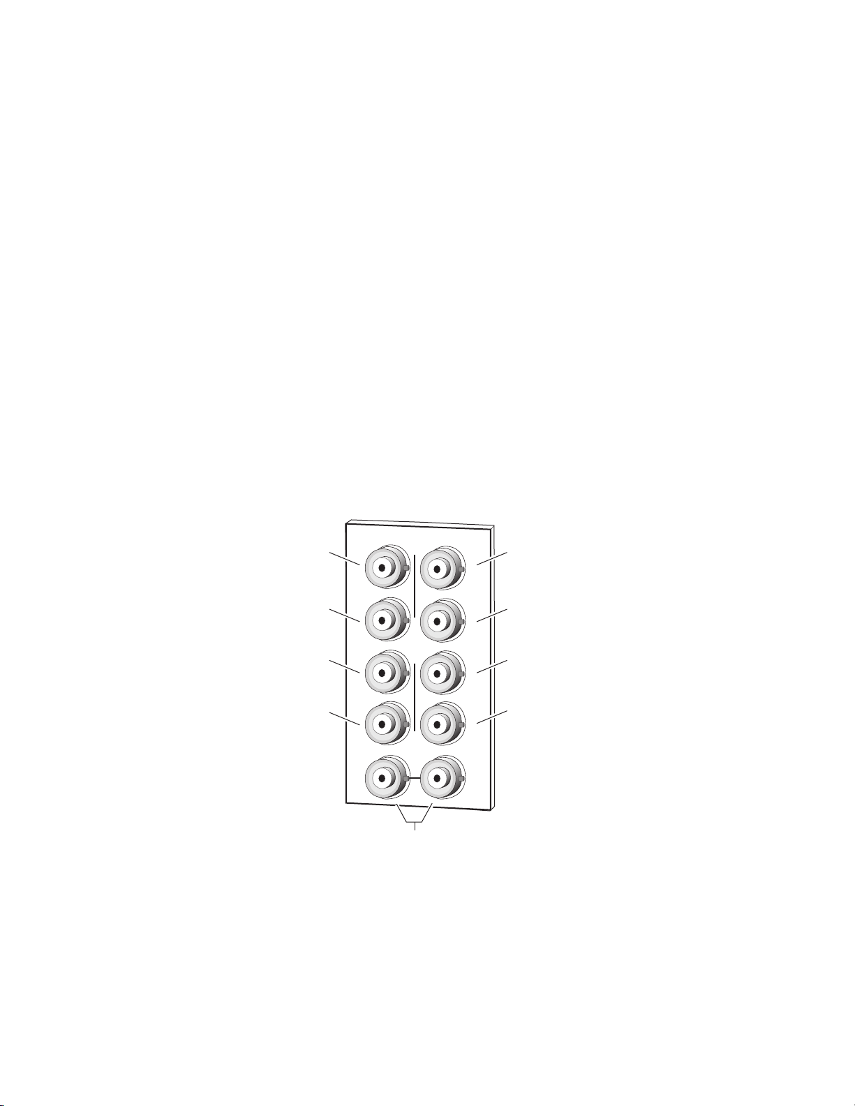
8900 module slots are interchangeable within the frame. There are 10 BNCs
in each slot’s I/O group. The functional assignment of each connector in a
group is determined by the module that is placed in that slot. The
maximum number of modules a Gecko 8900 video frame can accept is ten.
Figure 2 illustrates the rear connector plate for a Gecko 8900 video frame.
Figure 2. Gecko 8900 Series Video Frame Rear Connector
To install a module in the frame:
1. Insert the module, connector end first, with the component side of the
module facing to the right and the ejector tab to the top.
2. Verify that the module connector seats properly against the backplane.
8937/8937D — Instruction Manual 11
3. Press in the ejector tab to seat the module.
Page 12

Installation
GeckoFlex Frame
Installation of the 8937 and 8937D module in a GeckoFlex frame is a process
of:
1. Installing the 8900V-R rear module into the rear of the frame,
2. Setting local jumper settings if configuring the module with on-board
controls,
3. Placing the 8937 module in the corresponding front frame slot, and
4. Cabling and terminating signal ports.
Module Installation Precautions
Please read and follow the precautions listed below before installing the
front and rear modules:
• Use standard anti-static procedures during installation. As modules
can be installed or removed when the GeckoFlex frame is powered up,
before removing the cover, please use an anti-static bracelet tied to a
metal part of the frame.
• Install the rear module first, then the front module, then the optical submodule option (if used).
• When installing or removing a rear module, loosen or tighten the
screws holding the retainer clips to the frame manually with the
retainer clip tool provided inside the front cover of the frame (751version frames only). For 650- version frames without the tool, use a
2 mm (5/64”) hex screwdriver. Please do not use an electric screwdriver.
• Make every effort to leave the screws holding the retainer clips in place
(do not remove them completely). They are very small and can easily
drop into other equipment causing a shorting hazard. (Two turns of the
screw should be enough to loosen the screws, 3 turns or more will
remove it.)
• When installing a rear module, tighten the screws on the retainer clips
just until snug. Do not apply more force than is necessary to seat the
rear module. Refer to the rear retainer screw torque specification under
Mechanical in Tab le 7 on pa ge 41.
12 8937/8937D — Instruction Manual
Page 13
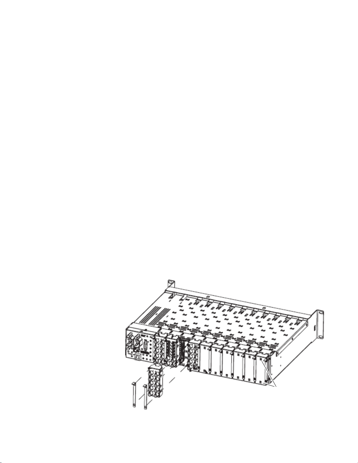
Rear Module Installation
Use needlenose pliers
to pull out blank after
removing retainers.
To install a rear module into the frame, follow these steps:
Note Please read Module Installation Precautions on page 12 before installing the
rear module.
1. Each 8900V-R rear module or blank rear adapter cover is held in place
by two retainer clips as shown in Figure 3. Loosen (but do not remove
completely) the two screws holding each retainer clip to the frame with
a 2 mm (5/64”) hex screwdriver. Pull up on the retainer to remove it,
leaving the screws in place.
CAUTION Be careful to leave the screws in place as they can be easily lost or fall into
equipment below the frame creating a shorting hazard.
2. Remove the blank rear adapter cover by inserting needlenose pliers
into the slots in the top and bottom of the blank and pulling it off.
Note To remove a rear module already installed, follow the same steps. It is helpful
to first remove the front module so the rear can be pulled out more easily.
Installation
3. Insert the rear module into the empty slot.
4. Replace each retainer clip over the two screws on both sides of the
module and push down to seat the retainer.
5. Tighten the screws for each retainer clip just until they are snug. Do not
force or torque the screws too tightly. The retainer screw torque
specification is 4-5 inch-lb/0.45-0.6Nm.
Figure 3. Installing Rear Module
8937/8937D — Instruction Manual 13
Page 14
Installation
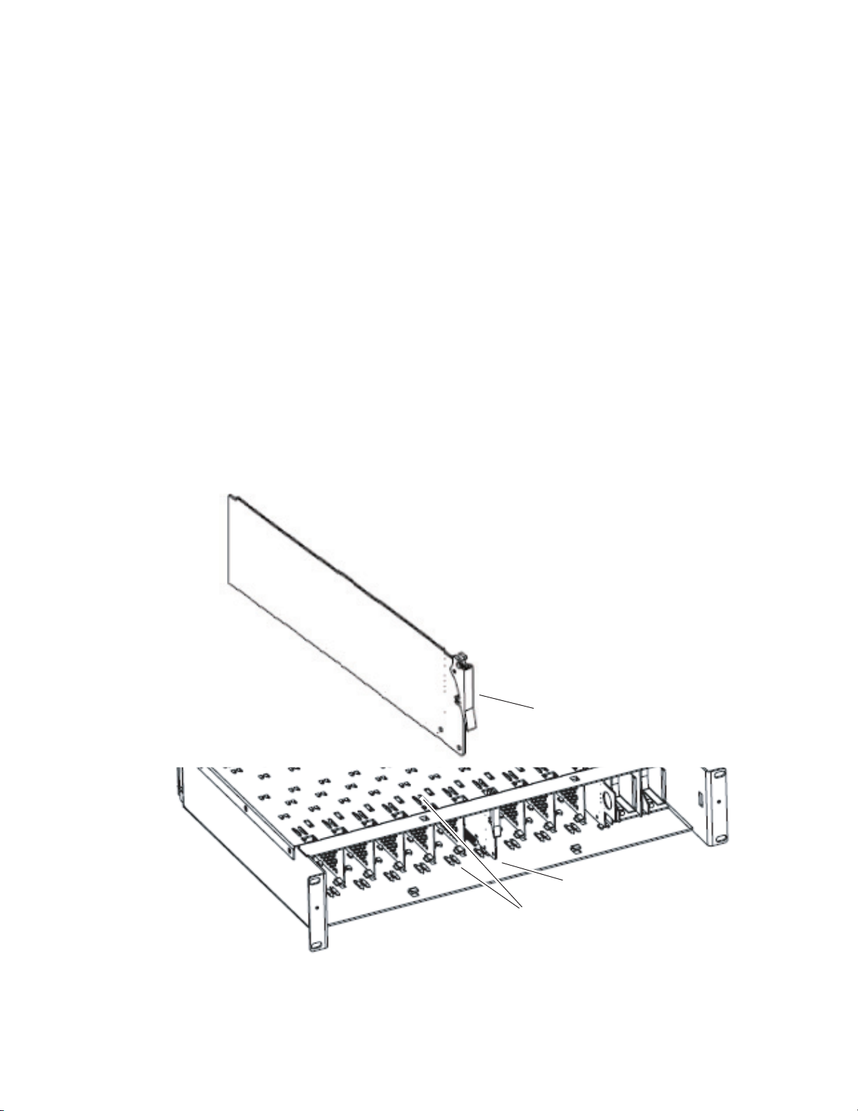
Front Module Installation
After installing the rear module, install the front module as follows:
Note If configuring the module using local on-board jumpers, set the jumpers
according to the instructions in Local On-Board Configuration on page 22
before installing the front module.
1. Remove the front cover of the frame.
2. Locate the corresponding front slot.
3. Insert the front module so that the plastic card guides on the module
top and bottom edges go over the upper and lower raised rail guides on
the right of the top and bottom of the slot(Figure 4).
4. Carefully slide the module into the rear connector.
5. Lock the front module ejector tab into the locking pin.
6. Reinstall the front cover of the frame during normal operation.
Figure 4. Front Module Installation
Front Module Side View
Locking Pin
0642_10r0
Module installed
Slide top and bottom card carriers on module
over top and bottom guides on right of slot.
14 8937/8937D — Instruction Manual
Page 15
Cabling
J2
J4
J6
J8
J9 J10
SDI Out 8
J3
J5
J7
J2J1
J4
J6
J8
8270_03
Differential
loop-through
SDI video inputs
SDI Out 1
SDI Out 3
SDI Out 5
SDI Out 2
SDI Out 4
SDI Out 6
SDI Out 7
8937 Module
Installation
Refer to Figure 5 for cabling the 8937 module. Cabling to and from the
module is done at the back of the Gecko 8900 video frame or on the corresponding 89000V-R rear module of the GeckoFlex frame as described
below.
Loop-Through Input
One serial digital component input is provided at differential loop-through
BNCs J9 and J10. If the unused input is not looped to another device, it
should be terminated in 75 ohm.
Outputs
There are eight outputs for the 8937 module at BNCs J1 through J8. Output
destination equipment should have an input impedance of 75 ohm unless
it has loop-through inputs, in which case the loop-through inputs must be
terminated into 75 ohm. All outputs are in phase with the input signal.
Figure 5. 8937 Rear Input/Output Connectors
8937/8937D — Instruction Manual 15
Page 16

Installation
J2
J4
J6
J8
Out 1-3
8270_09r1
SDI In 1
(differential loop-through)
Out 2-1
SDI In 2
(terminated)
Out 2-3
Out 2-2
Out 2-4
Out 1-1
Out 1-2
J9
J10
J3
J5
J7
J2
J1
J4
J6
J8
8737D Module
Refer to Figure 6 for cabling the 8937D module. Cabling to and from the
module is done at the back of the Gecko 8900 video frame or on the corresponding 8900V-R rear module on the GeckoFlex frame as described below.
DA 1 Inputs and Outputs
DA 1 provides one serial digital component input at loop-through BNCs J9
and J10. If the unused input is not looped to another device, it should be ter
minated in 75 ohm. The three outputs for DA 1 are from BNCs J6, J7, and
J8. All outputs are in phase with the input signal.
DA 2 Inputs and Outputs
DA 2 provides one terminated serial digital component input at BNC J5.
The four outputs for DA
in phase with the input signal.
Figure 6. 8937D Rear Input/Output Connectors
-
2 are from BNCs J1, J2, J3, and J4. All outputs are
Looping Capabilities
The reclocked output signal from one 8937 or 8937D module may be looped
to up to ten reclocked 8937 or 8937D modules in series for further distribu
tion without degrading the signal.
The output signal from modules operating in Bypass mode (not reclocked
to one of the standard rates) will begin to degrade by the third module in
the series. This looping is not recommended.
-
16 8937/8937D — Instruction Manual
Page 17

Power Up
Power Up
The front LED indicators and configuration switches are illustrated for the
8937 in
Figure 7. The front LED indicators for the 8937D module has an
additional row of identical LEDs labeled for DA 1 and DA 2 as shown in
Figure 8. Upon power-up, the green PWR LED should light and the yellow
CONF LED should illuminate for a few seconds for the duration of module
initialization.
Note When a module is first plugged into a frame, the 8900NET module (if present)
may report a momentary fault. This will clear once the module has booted up.
Figure 7. 8937 Front LEDs Indicators
FAULT COMM CONF PWR
GRASS VALLEY 8937D SDI/ASI RECLOCKING EQ SNMP DA
FAULT (red)
COMM (yellow)
CONF (yellow)
SIG
PRES
BYPASS 143Mb 177Mb 270Mb 360Mb REM
PWR (green)
SIG PRES
BYPASS
143Mb
177Mb
270Mb
360Mb
OVR
REM OVR
8937
8270_05r1
Figure 8. 8937D Front LED Indicators
FAULT COMM CONF PWR
GRASS VALLEY 8937D SDI/ASI RECLOCKING EQ SNMP DA
8937
FAULT (red)
COMM (yellow)
CONF (yellow)
PRES
SIG
BYPASS 143Mb 177Mb 270Mb 360Mb
PWR (green)
DA 2
SIG PRES
BYPASS
143Mb
177Mb
270Mb
360Mb
DA 2 LEDs
DA 1 LEDs
SIG PRES
BYPASS
143Mb
177Mb
270Mb
360Mb
PRES
OVR
DA 1
SIG
BYPASS 143Mb 177Mb 270Mb 360Mb REM
REM OVR
8270_12r0
8937/8937D — Instruction Manual 17
Page 18

Power Up
Operation Indicator LEDs
Refer to Figure 7 on page 17 (8937) and Figure 8 on page 17 (8937D) and
Ta bl e 2 for the name and meaning of each of the board edge LEDs on the
front of the module circuit board. Refer also to Tab le 3 on page 19 for specific LED states and module conditions.
Table 2. Board Edge LED Names and Meaning
LED 8937
FAULT
(red)
COMM
(yellow)
CONF
(yellow)
PWR
(green)
SIG PRES
(green)
BYPASS
(yellow)
143 Mb
(yellow)
177 Mb
(yellow)
270 Mb
(yellow)
360 Mb
(yellow)
REM OVR
(yellow)
1
If the module has recognized a remote override on one DA, removing the module and changing a jumper on the other DA and reinserting the module does not change
the status of the REM OVR LED.
Off Off Off Normal operation.
On continuously On On Module has detected an internal fault. (Refer to Service on page 42.)
Long Flash Long Flash Long Flash Input missing or input does not match bit rate set with manual mode.
Off Off Off No activity on frame communication bus.
Steady flash Steady flash Steady flash Locate Module command received by the module from a remote control system.
Short flash Short flash Short flash Activity present on the frame communication bus.
Off Off Off Module is in normal operating mode.
On continuously On On Module is initializing, changing operating modes or programming hardware.
Off Off Off No power to module or module’s DC/DC converter failed.
On On On Normal operation, module is powered.
Off Off Off No signal input detected or input signal does not match bit rate set with Manual mode
On On On
Off Off Off Reclocking is enabled and auto-rate detection mode is active
On On On
Off Off Off No 143 Mb speed signal present.
On On On Auto Mode: Input signal is locked at 143 Mb, Manual Mode: 143 Mb is present and locked.
Off Off Off No 177 Mb speed signal present.
On On On Auto Mode: Input signal is locked at 177 Mb, Manual Mode: 177 Mb is present and locked.
Off Off Off No 270 Mb speed signal present.
On On On Auto Mode: Input signal is locked at 270 Mb, Manual Mode: 270 Mb is present and locked
Off Off Off No 360 Mb speed signal present.
On On On Auto Mode: Input signal is locked at 360 Mb, Manual Mode: 360 Mb is present and locked
Off Off Module setting match those set on module switches and jumpers.
On On
8937D
DA 1 DA 2
Condition
In Auto or Bypass mode input signal is present or input signal matches bit rate set with Manual
mode.
Bypass mode is selected (input signal will not be reclocked); Auto mode is selected and input
signal is not present or input signal is not 143 Mb, 177 Mb, 270 Mb, or 360 Mb.
Remote control is overriding on-board jumper setting on last web page change on either DA 1 or
DA 2 made on module.
1
18 8937/8937D — Instruction Manual
Page 19

Ta bl e 3 gives an overall summary of the LED indicator and reported input
signal state for all possible mode conditions in Bypass, Auto, and Manual.
Table 3. Reported Input Status Summary
Operating
Mode
Bypass Not Present Off Off Off Off Off Yellow Muted
Bypass Present Green Off Off Off Off Yellow
Auto Not Present Off Off Off Off Off Yellow Muted
Auto
Auto
Auto
Auto
Auto
Manual
143 Mb
Manual
143 Mb
Manual
143 Mb
Manual
177 Mb
Manual
177 Mb
Manual
177 Mb
Manual
270 Mb
Manual
270 Mb
Manual
270 Mb
Input Carrier
Detect
Present,
(Not 143, 177,
270 or 360 Mb)
Present
(143 Mb
Locked)
Present
(177 Mb
Locked)
Present
(270 Mb
Locked)
Present
(360 Mb
Locked)
Not Present Off Off Off Off Off Off Muted
Present
(Not 143 Mb)
Present
(143 Mb
Locked)
Not Present Off Off Off Off Off Off Muted
Present
(Not 177 Mb)
Present
(177Mb
Locked)
Not Present Off Off Off Off Off Off Muted
Present
(Not 270 Mb)
Present
(270 Mb
Locked)
SIG
PRES
LED
Green Off Off Off Off Yellow
Green Yellow Off Off Off Off
Green Off Yellow Off Off Off
Green Off Off Yellow Off Off
Green Off Off Off Yellow Off
Off Off Off Off Off Off Muted
Green Yellow Off Off Off Off
Off Off Off Off Off Off Muted
Green Off Off Yellow Off Off
Off Off Off Off Off Off Muted
Green Off Off Yellow Off Off
143 Mb
LED
177 Mb
LED
270 Mb
LED
360 Mb
LED
BYPASS
LED
Reclocked
Reclocked
Reclocked
Reclocked
Reclocked
Reclocked
Reclocked
Output
Input
Signal
Input
Signal
143 Mb
177 Mb
270 Mb
360 Mb
143 Mb
177 Mb
270 Mb
Power Up
Input
Reporting
No Not Monitored
Yes Signal Not Present
No Not Monitored
Yes Signal Present
No Not Monitored
Yes Signal Not Present
No Not Monitored
Yes Signal Present
No Not Monitored
Yes Signal Present
No Not Monitored
Yes Signal Present
No Not Monitored
Yes Signal Present
No Not Monitored
Yes Signal Present
No Not Monitored
Yes Signal Not Present
No Not Monitored
Yes Not Present
Disabled Not Monitored
Enabled Not Present
No Not Monitored
Yes Signal Not Present
No Not Monitored
Yes Not Present
Disabled Not Monitored
Enabled Signal Present
No Not Monitored
Yes Not Present
No Not Monitored
Yes Signal Not Present
Disabled Not Monitored
Enabled Signal Present
Reported
Input State
8937/8937D — Instruction Manual 19
Page 20

Configuration
Operating
Mode
Manual
360 Mb
Manual
360 Mb
Manual
360 Mb
Input Carrier
Detect
Not Present Off Off Off Off Off Off Muted
Present
(Not 360 Mb)
Present
(360 Mb
Locked)
Configuration
Table 3. Reported Input Status Summary
SIG
PRES
LED
Off Off Off Off Off Off Muted
Green Off Off Off Yellow Off
143 Mb
LED
177 Mb
LED
270 Mb
LED
360 Mb
LED
BYPASS
LED
Output
Reclocked
360 Mb
Input
Reporting
No Not Monitored
Yes Signal Not Present
No Not Monitored
Yes Signal Not Present
No Not Monitored
Yes Signal Present
Reported
Input State
Configuration and monitoring can be performed using local jumper controls, a web browser GUI interface, or a networked Newton Control Panel.
This section provides an overview of each of these controls along with the
configuration parameters available with each type of control device.
Refer to the following sections for configuration information:
• Configuration Summary Table (page 21)
• Local On-board Controls (page 22)
• Remote Configuration and Monitoring (page 24)
20 8937/8937D — Instruction Manual
Page 21

Configuration Summary
The configuration parameters and monitoring functions available with the
local on-board jumpers, web browser interface, and the Newton Control
Panel are summarized in
and resolution are provided for each function.
Table 4. Summary of 8937/8937D Configuration Functions
Function
Type
Report Loss of Signal 1 Yes Yes or No
Input signal DA 1 status –
Mode 1 Auto
Current Bit Rate 1 – –
Standard Select 1
(Manual Mode)
Report Loss of Signal 2 Yes Yes or No
Input signal DA 2 status –
Mode 2 Auto
Current Bit Rate 2 – –
Standard Select 2
(Manual Mode)
Default
143 Mb
143 Mb
Range/Choices
Resolution
Signal Present
Signal Not Present
Not Monitored
Auto,
Manual
Bypass
143 Mb
177 Mb
270 Mb
360 Mb
Signal Present
Signal Not Present
Not Monitored
Auto
Manual
Bypass
143 Mb
177 Mb
270 Mb
360 Mb
Configuration
Ta bl e 4. The parameter defaults, choices, ranges,
Web Page/
Function Name
Standard Selections/
Report Loss of Signal 1
pulldown
Standard Selections/
Input Signal 1
Standard Selections/
Mode 1 pulldown
Standard Selections/
Current Bit Rate 1
Standard Selections/
Mode 1: Manual
Standard Selection 1
pulldown
Standard Selections/
Report Loss of Signal 2
pulldown
Standard Selections/
Input Signal 2
Standard Selections/
Mode2 pulldown
Standard Selections/
Current Bit Rate 2
Standard Selections/
Mode 2: Manual
Standard Selection 2
pulldown
On-Board Jumper
Setting
N/A RepLOS1
– Input Sig1
DA 1 J6: pins 1-2 – Auto
pin 2 only – 270 Mb
pins 2-3 – Bypass
–CurRt1
N/A StdSel1
N/A RepLOS2
– Input Sig2
DA 2 J5: pins 1-2 – Auto
pin 2 only – 270 Mb
pins 2-3 – Bypass
–CurRt2
N/A StdSel2
Newton
Control
Panel
Mode1
Mode2
8937/8937D — Instruction Manual 21
Page 22

Configuration
GRASS VALLEY 8937D SDI/ASI RECLOCKING EQ SNMP DA
8937
8270_06r2
FAULT COMM CONF PWR
SIG
PRES
BYPASS 143Mb 177Mb 260Mb 360Mb REM
OVR
J7
J6
DA 1
AUTO (1-2)
270 Mb (pin 2)
BYPASS (2-3)
LOCAL/REMOTE
LOCAL &
REMOTE (2-3)
LOCAL (1-2)
Pins 2-3
Pins 1-2
Pin 2 only
Jumper Positions for J6
Local On-Board Configuration
8937 Module
Two on-board jumpers are present on the 8937 module to configure module
formatting if not using the remote controls. Refer to
locations on the module circuit board.
• DA 1 – set jumper J6 for AUTO (pins 1-2) to enable auto reclocking (for
• Local/Remote – set jumper J7 to LOCAL (pins 1-2) to lock out remote
Figure 9. 8937 On-Board Jumper Locations
Figure 9 for jumper
signal data rates of 143, 177, 270, and 360 Mb/s), 270 Mb only (jumper
pin 2 only), or BYPASS (pins 2-3) to bypass reclocking (for signals with
data rates of 50 Mb/s to 360 Mb/s). This setting can be overridden by
remote controls.
control or LOCAL & REMOTE (pins 2-3) for access to remote control.
This setting cannot be overridden by remote controls.
22 8937/8937D — Instruction Manual
Page 23

8937D Module
GRASS VALLEY 8937D SDI/ASI RECLOCKING EQ SNMP DA
8937
FAULT COMM CONF PWR
SIG
PRES
DA 1
DA 2
BYPASS 143Mb 177Mb 270Mb 360Mb REM
OVR
SIG
PRES
BYPASS 143Mb 177Mb 270Mb 360Mb
8270_06r2
J5
J7
J6
DA 1
AUTO (1-2)
270 Mb (pin 2)
BYPASS (2-3)
LOCAL/REMOTE
LOCAL &
REMOTE (2-3)
LOCAL (1-2)
DA 2
AUTO (1-2)
270 Mb (pin 2)
BYPASS (2-3)
Pins 1-2
Pins 2 only
Pins 2-3
Jumper Positions for J5/J6
Three onboard jumpers are present on the 8937D to configure module formatting. Refer to Figure 10 for jumper locations on the circuit board.
• DA 2 BYPASS/270 Mb/AUTO – for DA 2, set jumper J5 for AUTO
(pins 1-2) to enable auto reclocking (for signal data rates of 143, 177,
270, and 360 Mb/s), 270 Mb only (jumper pin 2 only), or BYPASS
(pins 2-3) to bypass reclocking (for signals with data rates of 50 Mb/s
to 360 Mb/s). This jumper setting can be overridden by remote controls.
• DA 1 BYPASS/270 Mb/AUTO – for DA 1, set jumper J6 for AUTO
(pins 1-2) to enable auto reclocking (for signal data rates of 143, 177,
270, and 360 Mb/s), 270 Mb only (jumper pin 2 only), or BYPASS
(pins 2-3) to bypass reclocking (for signals with data rates of 50 Mb/s
to 360 Mb/s). This jumper setting can be overridden by remote controls.
• Local/Remote – set jumper J7 to LOCAL (pins 1-2) to lock out remote
control or LOCAL & REMOTE (pins 2-3) for access to remote control.
This jumper setting cannot be overridden by remote controls.
Figure 10. 8937D On-Board Jumper Locations
Configuration
8937/8937D — Instruction Manual 23
Page 24

Configuration
Remote Configuration and Monitoring
8937/8937D configuration and monitoring can be performed using a web
browser GUI interface or a networked Newton Control Panel when the
8900NET (Net Card) Network Interface module is present in the video
frame (Gecko 8900TFN-V frame). Each of these interfaces are described
below.
Note For remote access, make sure the jumper block on the module is set for both
Local and Remote access (Figure 9 on page 22 and Figure 10 on page 23).
8900NET Module Information
Refer to the 8900NET (Net Card) Network Interface Module Instruction Manual
for information on the 8900NET Network Interface module and setting up
and operating the Gecko 8900 frame network.
Note The 8900NET module in the frame must be running software version 4.2.0 or
higher for proper remote control panel operation. Upgrade software and
instructions for the 8900NET can be downloaded from the Grass Valley ftp
site at ftp://ftp.thomsongrassvalley.com/modular/8900net.
Newton Control Panel Configuration
A Newton Control Panel (hard or soft version) can be interfaced to the
Gecko 8900 Series frame over the local network. Refer to the documentation
that accompanies the Newton Modular Control System for installation,
configuration, and operation information.
Control panel access offers the following considerations for module configuration and monitoring:
• Ability to separate system level tasks from operation ones, minimizing
the potential for on-air mistakes.
• Ability to group modular products—regardless of their physical locations—into logical groups (channels) that you can easily manipulate
with user-configured knobs.
• Update software for applicable modules and assign frame and panel IP
addresses with the NetConfig Networking application.
• Recommended for real-time control of module configuration parameters, providing the fastest response time.
Note Not all module functions are available with the control panel, such as factory
default recalls. The available control panel controls for the module are listed
in Table 4 on page 21.
24 8937/8937D — Instruction Manual
Page 25

Configuration
An example of the Newton Configurator is shown in Figure 11.
Figure 11. Newton Configurator Example
Web Browser Interface
The web browser interface provides a graphical representation of module
configuration and monitoring.
Use of the web interface offers the following considerations:
• Provides complete access to all module status and configuration func-
tions, including naming of inputs and outputs, factory parameter and
name default recalls, E-MEM functions, slot configuration, and SNMP
monitoring controls.
• Web access will require some normal network time delays for pro-
cessing of information.
• Configuration parameter changes may require pressing
Enter, upload processing time, and a manual screen refresh to become
effective.
• Web interface recommended for setting up module signal and slot
names, E-MEMs, and reporting status for SNMP and monitoring.
Refer to the Frame Status page shown in Figure 12 on page 26. The 8900
modules can be addressed by clicking either on a specific module icon in
the frame status display or on a module name or slot number in the link list
on the left.
Apply button or
8937/8937D — Instruction Manual 25
Page 26

Configuration
8270_11r0
The Links section lists the frame and its current modules. The selected link's Status
page is first displayed and the sub-list of links for the selection is opened. The sub-list
allows you to select a particular information page for the selected device.
Content display section dis
plays the information page
for the selected frame or module (frame slot icons are also
active links).
Refresh button for manual
update of page
Note The physical appearance of the graphics on the web pages shown in this
manual represent the use of a particular platform, browser and version of
8900NET (Net Card) module software. They are provided for reference only.
Web pages will differ depending on the type of platform and browser you are
using and the version of the 8900NET software installed in your system. This
manual reflects 8900NET software version 4.2.0 required for this module.
For information on status and fault monitoring and reporting shown on the
Status page, refer to Status Monitoring on page 38.
Figure 12. Frame Status Page
26 8937/8937D — Instruction Manual
Page 27

8937 and 8937D Links and Web Pages
The 8900 GUI provides the following links and web pages for the 8937 and
8937D modules (
• Status – reports input signal and frame bus communication status and
module information (page 28),
• Standard Selections –allows enabling and disabling of signal loss
reporting and selection of the standard selections and modes (page 30),
• Recall Factory Defaults – provides factory default recall (page 34), and
• Slot Config – provides a Locate Module function, Slot Identification
fields, and Slot Memory controls, and links to the 8900NET Frame
Reporting, LED Reporting, and SNMP web pages (page 35).
Figure 13. 8937 and 8937D Web Page Links
Figure 13):
Configuration
Refer to Table 4 on page 21 for a complete summary of web page control
parameter defaults, choices, ranges, and resolutions.
8937/8937D — Instruction Manual 27
Page 28

Configuration
Use
this
link
Status Web Page
The Status web page (Figure 14 on page 29 for 8937 and Figure 15 on
page 29
communication with the frame bus. Color coding
the signal status. In general, graphics and text colors used for status indication are the following:
• Green = Pass – signal or reference present, no problems detected.
•
Red = Fault – fault condition.
• Yellow = Warning – signal is absent, has errors, or is mis-configured.
• Gray = Not monitored.
Note Always refresh the page first with the Refresh button at the top of the page
On the Status web page for the 8937D module, signal status of both input
signals is represented by a single input signal arrow. Signal reporting to this
status indicator can be disabled at the module level for either or both DA 1
and DA 2 on the Standard Selection web page. When input signal status
reporting is enabled for both DAs, if the status of either input signal
changes, it will be reflected in the color status of the arrow and the Status
LED on the module web pages. To determine which signal has been
affected, refer to the Standards Selection web page or the on-board front
edge LEDs.
for the 8937D) shows the signal status of the input signal(s) and
of the display indicates
(shown at left) to update the current status of the web page.
The collective input state for the 8937D input signal arrow is summarized
in Tab le 3 . In the table under DA 1 and DA 2,
Report Loss of Signal control for that DA has been disabled on the Standard
Not Monitored indicates the
Selection web page. For SNMP reporting, the reporting is separate for each
DA. Refer to SNMP Trap Reports on page 37.
Table 5. 8937D Collective Status State for Input Signal
DA 1
Input Status
Not Monitored Not Monitored Not Monitored Gray
Signal Not Present N/A Signal Not Present Yellow
N/A Signal Not Present Signal Not Present Yellow
Signal Present Not Monitored Signal Present Green
Not Monitored Signal Present Signal Present Green
Signal Present Signal Present Signal Present Green
1
When signal loss reporting for both DAs is disabled, the Status LED on each web page will continue to monitor module
status but will not respond to signal status changes.
DA 2
input Status
Collective
Input Status
Input Signal Arrow
Color
1
Information about the module, such as part number, serial number, hardware revision, software version, and Asset Tag number are given in a
erties
section at the bottom of the Status page display.
Prop-
28 8937/8937D — Instruction Manual
Page 29

Figure 14. 8937 Status Web Page
Configuration
Figure 15. 8937D Status Web Page
8937/8937D — Instruction Manual 29
Page 30

Configuration
Use
this
link
Standard Selections Web Page
The Standard Selections web page allows you to set loss of signal reporting
and the operating mode for the 8937 and 8937D modules. Refer to the specific 8937 or 8937D heading below.
8937 Module
Refer to Figure 16 for the Standard Selections web page for the 8937.
Select the
Set the following parameters on this web page:
• Set the Report Loss of Sig 1 input presence reporting to
abling this control will gray out the Input Signal(s) arrow on the Status
web page graphic shown in Figure 14 on page 29.
• The Input Signal 1 field will report the status of the input signal as one
of the following:
• Signal Present,
• Signal Not Present, or
•
• When the Mode 1 control is set to
detected by module and displayed in the
• When
Rate1
Figure 16. 8937 Standards Selections Web Page
Apply button after making each selection.
Yes or No. Dis-
Not Monitored (Report Loss of Sig 1 set to No)
Auto, the input bit rate standard is
Current Bit Rate1 field.
Bypass is set for Mode 1, Bypass will be displayed in the Current Bit
field.
30 8937/8937D — Instruction Manual
Page 31

Configuration
When Manual mode is selected in the Mode 1 pulldown and the Apply
button is selected, a Standard Selection 1 pulldown will appear as shown
in
Figure 17 to allow setting a specific bit rate.
Select a bit rate from the Standard Selection 1 pulldown from one of the following:
143 Mb,
•
177 Mb,
•
270 Mb, or
•
• 360 Mb
The currently selected manual rate will be shown next to the pulldown.
Note In Manual mode, if the input signal does not match the selected standard,
Signal Not Present will be reported in the Input Signal description.
Figure 17. 8937 Operating Mode Set to Manual
8937/8937D — Instruction Manual 31
Page 32

Configuration
8937D Module
The Standard Selections page for the 8937D (Figure 18 on page 33) provides
separate controls for DA 1 and DA 2 signal loss reporting and standard
selection.
Note Each DA has a separate Report Loss of Signal control. On the Status web
page, input signal status reporting is collective as described in Status Web
Page on page 28. SNMP reporting is separate as described in SNMP Trap
Reports on page 37.
Click the Apply button to enter all values.
For DA 1:
• Set Report Loss of Sig 1 as
• Set the Mode 1 control for DA 1 to
by module),
Bypass (input bypasses reclocking circuitry).
Manual (input bit rate standard selected manually), or
Yes or No. See Note above.
Auto (input bit rate standard detected
• The Input Signal 1 field will report the status of the DA 1 input signal.
• When
Auto mode is selected, the bit rate currently detected by the
module will be displayed in the Current Bit Rate 1 field as shown in the
example in Figure 18 on page 33.
• When
Bypass mode is selected, Bypass will be displayed in the Current
Bit Rate 1 field.
• When
Manual mode is selected, a Standard Selection 1 pulldown will
appear similar to the one shown previously in the 8937 DA 1 illustration in Figure 17 on page 31. Select the bit rate from the Standard Selec-
tion 1 pulldown (
143 Mb, 177 Mb, 270 Mb, or 360 Mb) as desired. The
currently selected manual rate will be shown next to the pulldown.
For DA 2:
• Set Report Loss of Sig 2 as
• Set the Mode 2 control for DA 2 to
by module),
Bypass (input bypasses reclocking circuitry).
Manual (input bit rate standard selected manually), or
Yes or No. See Note above.
Auto (input bit rate standard detected
• The Input Signal 2 field will report the status of the DA 2 input signal.
• When
Auto mode is selected, the bit rate currently detected by the
module will be displayed in the Current Bit Rate 2 field.
• When
Bypass mode is selected, Bypass will be displayed in the Current
Bit Rate 1 field as shown in the example in DA 2 in Figure 18 on page 33.
• When
Manual mode is selected, a Standard Selection 2 pulldown will
appear. Select the bit rate from the Standard Selection 2 pulldown
(
143 Mb, 177 Mb, 270 Mb, or 360 Mb) as desired. The currently selected
manual rate will be shown next to the pulldown.
32 8937/8937D — Instruction Manual
Page 33

Configuration
Note In Manual mode, if the input signal does not match the selected standard,
Signal Not Present will be reported in the Input Signal 2 description.
Figure 18. 8937D Standard Selection Web Page
8937/8937D — Instruction Manual 33
Page 34

Configuration
Use
this
link
Recall Factory Defaults Web Page
Use the Recall Factory Defaults web page (Figure 19) to recall preset factory
defaults as listed in Ta bl e 4 on page 21.
Note For the 8937D module, this will recall factory defaults for both DAs.
Figure 19. 8937 and 8937D Recall Factory Defaults Web Page
34 8937/8937D — Instruction Manual
Page 35

Slot Config Web Page
Use
this
link
Use the Slot Config web page (Figure 20 on page 36) to perform the following functions on the module:
Locate Module
Selecting the Flash button flashes the yellow COMM and CONFIG LEDs in
unison on the front of the module so it can be located in the frame.
Slot Identification
You may identify the module by typing a specific name in the Name field.
The assigned name is stored on the 8900NET module and travels with the
8900NET module if it is moved to another frame. Select
factory default module name.
Configuration
Default to enter the
An asset identification may be entered in the
ters. This will appear on the module Status web page and in the NetConfig
PC application inventory report.
Asset Tag field up to 31 charac-
Slot Memory
When the Restore upon Install checkbox on any media module Slot Config
web page has been selected, the current configuration from that module is
saved in slot memory on the 8900NET module. This allows the current
module to be removed and when another module of the same part number,
and software version is installed, the configuration saved to the 8900NET
module will be downloaded to the installed module. The
checkbox must be selected before the current module with the saved configuration is removed.
Note Make sure all modules of the same model type are running the same software
version and have the same part number silk-screened on the printed circuit
board. Downloading a configuration to a module with a different software
version or part number can produce unexpected results.
If a different type of module is installed in this slot, a warning message will
state that the original module type has been replaced with another module
type. In this case, a
configuration from the previous module.
Clear button will appear allowing you to clear the stored
Restore upon Install
You may also select the
current configuration for this slot. The configuration is saved on the
8900NET module. If the 8900NET module is removed or powered down,
the stored configurations are not saved.
Note Uncheck the Restore Upon Install button before downloading new software.
8937/8937D — Instruction Manual 35
Learn Module Config button at any time to save the
Page 36

Configuration
Figure 20. Slot Config Web Page
Frame Health Reporting
Provides a link to the Frame Health Reports web page. This web page
allows configuration of the alarms and warnings that are reported to the
external Frame Health Alarm connector on the rear of the GeckoFlex frame.
Refer to 8900NET Instruction Manual for more details.
LED Reports
This link appears when the 8900NET module has software version 4.0.2 or
later installed. When the link is selected, a read-only status report of the
8900NET Hardware Switch state is given. In the LED Reporting section of
the web page, LED Reporting can be enabled or disabled as desired.
36 8937/8937D — Instruction Manual
Page 37

Configuration
SNMP Trap Reports
Select the SNMP Trap Reports link to open the 8900NET SNMP Reporting
web page. this link will only be present when SNMP Agent software has
been installed on the 8900NET module. This web page allows configura
tion of which alarms and warnings that are reported to the SNMP management software.
This module has separate Module Specific SNMP traps for reporting the
loss of signal for the 8937D for DA 1 and DA 2. The signal loss reporting for
SNMP traps is not collective as it is for the Status web page signal input
reporting as described in the Status Web Page on page 28.
The Module Specific Traps are defined in Tab le 6.
Table 6. Module Specific Signal Status Traps
Trap Type Trap Source Trap Severity Trap Message
Generic Input 1 Informational In 1 is now Present
Generic Input 1 Informational In 1 is not Present
Generic Input 1 Warning In 1 is Not Monitored
Generic Input 2 Informational In 2 is now Present
Generic Input 2 Informational In 2 is not Present
Generic Input 2 Warning In 2 is Not Monitored
-
Refer to 8900NET (Net Card) Network Interface Module Instruction Manual for
more details on the links to the 8900NET module.
8937/8937D — Instruction Manual 37
Page 38

Software Updating
Software Updating
If a software update becomes available for this module, the software
upgrade procedure will be described in the specific release notes posted on
the Thomson Grass Valley ftp and web sites.
Status Monitoring
There are a number of ways to monitor frame and module status. These
methods are summarized here. For more detailed information, refer to the
8900NET (Net Card) Network Interface Module Instruction Manual and the
8900 Gecko or 8900 GeckoFlex Frame Instruction Manuals.
All modular product documentation is available on-line in PDF format at
this link:
http://www.thomsongrassvalley.com/docs/modular
The main status monitoring methods include the following:
• External frame alarm output on the rear of the 8900 frame with
reporting from the Module Health Bus and other frame status alarm
reports,
• LEDs on the Frame, 8900NET module, and individual frame media
modules,
• Web browser status reporting for each frame component, and
• SNMP traps, captured by Thomson Grass Valley’s NetCentral or
another SNMP Manager Application.
Note SNMP trap information is only available when an SNMP Agent has been
installed and configured.
38 8937/8937D — Instruction Manual
Page 39

External Frame Alarm
An external Frame Alarm output is available on pins 8 and 9 of the RS-232
connector on the rear of the frame. The Frame Alarm outputs a voltage
level indicating there is an alarm condition on the Module Health Bus or
one of the other frame components reported to the Frame Monitor module
in a Gecko 8900TF or GeckoFlex 8900FF frame or the 8900NET module in
an 8900TFN and GeckoFlex 8900FFN frame.
• The Module Health bus is a separate line on the frame motherboard
that provides a means for older or less capable modules (such as DAs
with no microprocessor) that cannot communicate over the Frame
(serial) bus to report warning and alarm conditions to the external
Frame Alarm. All media modules in the frame report a voltage level to
this line when a warning condition occurs on the module. The specific
warning or module location is not reported, only an indication that an
warning condition has occurred.
• Frame alarm reporting from other frame components can be enabled
and disabled using DIP switches on the Frame Monitor and 8900NET
module. For frames with an 8900NET module, the Frame Alarm
Reporting web page allows configuration of the alarms and warnings
that are reported to this external Frame Health Alarm.
Status Monitoring
LED Reporting
LEDs on the front of media modules, the Frame Monitor or 8900NET modules, and the front covers of the 8900TF/TFN and GeckoFlex FF/FFN
frames indicate status of the frame and the installed power supplies, fans
in the front covers, and module status. (The 8900TX-V/A and GeckoFlex
8900FX frames have no LED indicators on the front cover.)
• LED reporting from the modules in the frame to the 8900NET module
is configurable using the 8900NET LED Reporting web page.
• The Status LEDs for this module are described in Operation Indicator
LEDs on page 18. LEDs for the 8900NET module are described in the
8900NET (Net Card) Network Interface Instruction Manual.
8937/8937D — Instruction Manual 39
Page 40

Status Monitoring
Web Browser Interface
SNMP Reporting
The 8900NET module controls a web browser GUI that indicates frame and
module status on the following web pages:
• Frame Status web page – reports overall frame and module status in
colored graphical and text formats. Refer to Figure 12 on page 26 for an
example.
•Module Status web page (Figure 14 on page 29) – shows specific input
and reference signal configuration error status to the module along
with module status and information (part number, serial number, hardware version, software/firmware/boot versions, and Asset number (as
assigned on the Slot Config web page).
• A Status LED icon on each web page reflects the module status on the
module Status web page where warnings and faults are displayed and
is a link to the module Status web page.
The Gecko 8900 Series system uses the Simple Network Monitoring Protocol (SNMP) internet standard for reporting status information to remote
monitoring stations. When SNMP Agent software is installed on the
8900NET module, enabled status reports are sent to an SNMP Manager
such as the Grass Valley’s NetCentral application.
Status reporting for the frame is enabled or disabled with the configuration
DIP switches on the 8900NET module. Most module status reporting items
can be enabled or disabled on individual configuration web pages.
40 8937/8937D — Instruction Manual
Page 41

Specifications
Specifications
Table 7. 8937 and 8937D Specifications
Parameter Value
Serial Digital Component Inputs
Number of inputs 8937: 2 BNC differential loop-through
Input impedance High Z
Signal type Conforming SDI SMPTE 259M (143 Mb/s, 177 Mb/s, 270 Mb/s, 360 Mb/s),
Reclocked data rates 143 Mb/s, 177 Mb/s, 270 Mb/s, and 360 Mb/s
Supported data rates 50 Mb/s to 360 Mb/s with maximum P/N of 19/1
Signal level SDI 800 mV p-p (± 10% maximum)
Return loss > 15 dB, 4 MHz to 360 MHz
Automatic cable equalization
(1694A cable)
Serial Digital Component Outputs
Number of outputs 8937: 8 BNCs
Output impedance 75 ohm
Signal types Conformed SDI SMPTE 259M (143 Mb/s, 177 Mb/s, 270 Mb/s, 360 Mb/s),
Signal level SDI 800 mV p-p (± 10% maximum)
Return loss > 15 dB 4 MHz to 360 MHz
Error checking Transparent to embedded EDH
Electrical length < 20 ns
Output polarity Non-inverted
Rise and fall time 400 – 700 ps
Jitter < 0.2 UI
Environmental
Frame temperature range Refer to frame specification
Operating humidity range 10 to 90% non-condensing
Non-operating temperature –10 to + 70 degrees C
Mechanical
Frame type Gecko 8900 Video
Rear retainer clip screw torque 4-5 inch-lb/0.45-0.6Nm
Power
Power consumption < 3 W
8937D: DA 1 – 2 BNC loop-through
8937D: DA 2 – 1 terminated BNC
DVB-ASI (passing 50 Mb/s to 360 Mb/s with maximum P/N of 19/1)
Up to 300 meters for SDI SMPTE signals up to 270 Mb/s
Up to 200 meters up to 360 Mb/s
8937D: DA 1 – 3 BNCs
8937D: DA 2 – 4 BNCs
DVB-ASI (passing 50 Mb/s to 360 Mb/s with maximum P/N of 19/1)
GeckoFlex with 8900V-R Rear Module
Video/8800/8500 (with trace cut and with certain power and return loss limitations)
8937/8937D — Instruction Manual 41
Page 42

Service
GRASS VALLEY 8937D SDI/ASI RECLOCKING EQ SNMP DA
8937
F1
2AMP
125V
FAST
8270_08
FAULT COMM CONF PWR
SIG
PRES
BYPASS 143Mb 177Mb 260Mb 360Mb REM
OVR
J8
Voltage
Test Points
2
+5V
GND
Fuse
Service
The 8937 and 8937D modules make extensive use of surface-mount technology and programmed parts to achieve compact size and adherence to
demanding technical specifications. Circuit modules should not be ser
-
viced in the field unless directed otherwise by Customer Service.
If your module is not operating correctly, proceed as follows:
• Check frame and module power and signal present LEDs.
• Verify power at the voltage testpoints (see Figure 21) and check fuse if
no voltage is detected.
• Check for presence and quality of input signals.
• Verify that source equipment is operating correctly.
• Check cable connections.
Refer to Figure 7 on page 17 for the location of the PWR LED and Tab le 2
on page 18 for proper LED indications.
If the module is still not operating correctly, replace it with a known good
spare and return the faulty module to a designated Grass Valley repair
depot. Call your Grass Valley representative for depot location.
Refer to the Contacting Grass Valley on page 4 at the front of this document
for the Grass Valley Customer Service Information number.
Figure 21. 8937 and 8937D Fuse and Voltage Testpoint Locations
42 8937/8937D — Instruction Manual
Page 43

Functional Description
Input and Output Processing
The input section(s) receive SD (standard definition) video from the rear
input BNCs and send it to signal equalizing and reclocking circuits. The
input section can also bypass reclocking circuits to the output amplifiers.
The output amplifiers drive eight equal-phase outputs on the rear back
plane for the 8937 and one set of four outputs and one set of three outputs
for the 8937D.
Note All outputs are in phase with the input signal.
Microprocessor and Input Selector
The primary purpose of the microprocessor is to provide remote control
and monitoring capability for the module. It receives signal present, signal
lock, and speed detection signals from the equalizer and reclocker circuits.
Using this information, local jumper settings, and remote control com
mands, the microprocessor selects the internal signal path and gives feedback through the LEDs and remote control bus.
Functional Description
-
-
User-enabled video presence detection generates individual SNMP traps
for each channel that can be sent to an SNMP manager via the microprocessor
8937/8937D — Instruction Manual 43
Page 44

Functional Description
44 8937/8937D — Instruction Manual
Page 45

Index
Numerics
143 Mb LED 18, 19
177 Mb LED 18, 19
270 Mb LED 18, 19
360 Mb LED 18, 19
8900A-R rear module (GeckoFlex frame)
installation
8900NET (Net Card)
installing
software version required 24
8937 module
features
frame types 41
Gecko 8900 frame installation 10
GeckoFlex 8900 frame installation 12
8937D module
features
frame types 41
Gecko 8900 frame installation 10
GeckoFlex 8900 frame installation 12
13
11
9
9
A
Asset Tag assignment 35
B
blank rear cover
GeckoFlex 8900 frame
BYPASS LED 18, 19
13
onboard (8937D) 23
Remote, GUI 24
summary table 21
connectors
Gecko 8900 frame
GeckoFlex 8900 frame 13
control panel 24
11
D
documentation online 4
E
environmental 41
F
FAQ database 4
FAULT LED
18
states
Frame Health Reporting (8900NET) 36
Frame Status web page 40
frequently asked questions 4
front module
GeckoFlex 8900 frame installation
functional description 43
fuse 42
14
G
Gecko 8900 frame
C
cabling
15
8937
8937D 16
Clear button 35
COMM LED 18
CONF LED 18
configuration
on-board (8937)
8937/8937D — Instruction Manual 45
22
backplane
frame capacity 10
module installation 10
module placement 11
rear connectors 11
GeckoFlex 8900 frame
frame alarm
front module installation 14
module installation 12
rear module installation 13
11
39
Page 46

Index
graphical user interface (GUI) 27
Grass Valley web site 4
I
input status summary 19
inputs
cabling (8937)
cabling (8937D) 16
specification 41
installation
Gecko 8900 frame modules
GeckoFlex 8900 frame modules 12
15
10
L
LED Reporting (8900NET) 36
LEDs
detailed summary table
Names and Meanings table 18
Locate Module 35
looping modules 16
19
M
Manual Mode
31
8937
8937D 32
summary table 21
Mode 1
remote control
summary table 21
Mode 2 (8937D)
remote control
summary table 21
Module Health Bus 39
Module Status web page 40
32
32
N
Newton Control Panel
control summary table
overview 24
21
O
outputs
cabling (8937)
cabling (8937D) 16
specification 41
15
P
power 41
power up 17
PWR LED 18
R
rear connectors 11
rear module (GeckoFlex 8900 frame)
installation
Recall Factory Defaults web page 34
REM OVR LED 18
repair depot 42
Report Loss of Signal
remote control
SNMP traps for DA 1 and DA 2 37
summary table 21
Restore upon Install checkbox 35
retainer clips (GeckoFlex rear module)
screw torque specification
12
30
13
S
SIG PRES LED 18, 19
Slot Config web page 35
Slot Identification 35
Slot Memory 35
SNMP reporting
Loss of Signal traps
overview 40
SNMP Trap Reports (8900NET) 37
software download from web 4
specifications 41
Standard Selections web page
30
8937
8937D 32
status monitoring 38
Status web page 28
37
online documentation 4
46 8937/8937D — Instruction Manual
Page 47

T
testpoints 42
troubleshooting 42
V
voltage tespoints 42
W
web browser
overview
web site
documentation
FAQ database 4
Grass Valley 4
software download 4
25
4
Index
8937/8937D — Instruction Manual 47
Page 48

Index
48 8937/8937D — Instruction Manual
 Loading...