

Page 1
8925EMB-B and -U
SD/HD DIGITAL AUDIO EMBEDDER MODULES
Instruction Manual
Software Version 2.1.6
071847806
MAY 2012
Page 2

CERTIFICATE
Certificate Number: 510040.001
The Quality System of:
Grass Valley USA, LLC and its Grass Valley Affiliates
Headquarters:
400 Providence Mine Road
Nevada City, CA 95945
United States
15655 SW Greystone Ct.
Beaverton, OR 97006
United States
Brunnenweg 9
D-64331 Weiterstadt
Germany
Kapittelweg 10
4827 HG Breda
The Nederlands
2300 So. Decker Lake Blvd.
Salt Lake City, UT 84119
United States
Including its implementation, meets the requirements of the standard:
ISO 9001:2008
Scope:
The design, manufacture and support of video and audio hardware and software products and related
systems.
This Certificate is valid until: June 14, 2012
This Certificate is valid as of: December 23, 2010
Certified for the first time: June 14, 2000
H. Pierre Sallé
President
KEMA-Registered Quality
The method of operation for quality certification is defined in the KEMA General Terms And Conditions For
Quality And Environmental Management Systems Certifications. Integral publication of this certificate is allowed.
KEMA-Registered Quality, Inc.
4377 County Line Road
Chalfont, PA 18914
Ph: (215)997-4519
Fax: (215)997-3809
CRT 001 042108
ccredited By:
ANAB
A
Page 3

8925EMB-B and -U
SD/HD DIGITAL AUDIO EMBEDDER MODULES
Instruction Manual
Software Version 2.1.6
071847806
MAY 2012
Page 4
Contacting Grass Valley
International
Support Centers
Local Support
Centers
(available
during normal
business hours)
France
24 x 7
Australia and New Zealand: +61 1300 721 495 Central/South America: +55 11 5509 3443
Middle East: +971 4 299 64 40 Near East and Africa: +800 8080 2020 or +33 1 48 25 20 20
Europe
+800 8080 2020 or +33 1 48 25 20 20
Hong Kong, Taiwan, Korea, Macau: +852 2531 3058 Indian Subcontinent: +91 22 24933476
Asia
Southeast Asia/Malaysia: +603 7805 3884 Southeast Asia/Singapore: +65 6379 1313
China: +861 0660 159 450 Japan: +81 3 5484 6868
Belarus, Russia, Tadzikistan, Ukraine, Uzbekistan: +7 095 2580924 225 Switzerland: +41 1 487 80 02
S. Europe/Italy-Roma: +39 06 87 20 35 28 -Milan: +39 02 48 41 46 58 S. Europe/Spain: +34 91 512 03 50
Benelux/Belgium: +32 (0) 2 334 90 30 Benelux/Netherlands: +31 (0) 35 62 38 42 1 N. Europe: +45 45 96 88 70
Germany, Austria, Eastern Europe: +49 6150 104 444 UK, Ireland, Israel: +44 118 923 0499
Copyright © Grass Valley USA, LLC. All rights reserved.
This product may be covered by one or more U.S. and foreign patents.
United States/Canada
24 x 7
+1 800 547 8949 or +1 530 478 4148
Grass Valley Web Site
The www.grassvalley.com web site offers the following:
Online User Documentation — Current versions of product catalogs, brochures,
data sheets, ordering guides, planning guides, manuals, and release notes
in .pdf format can be downloaded.
FAQ Database — Solutions to problems and troubleshooting efforts can be
found by searching our Frequently Asked Questions (FAQ) database.
Software Downloads — Download software updates, drivers, and patches.
4 8925EMB-B and -U — Instruction Manual
Page 5

Contents
Preface. . . . . . . . . . . . . . . . . . . . . . . . . . . . . . . . . . . . . . . . . . . . . . . . . . . . . . . . . . . . . . . . . . . . . 7
8925EMB-B and -U SD/HD Digital Audio Embedder . . . . . . . . . . . . . . . . . . . . 9
About This Manual . . . . . . . . . . . . . . . . . . . . . . . . . . . . . . . . . . . . . . . . . . . . . . . . . . . . . 7
Introduction . . . . . . . . . . . . . . . . . . . . . . . . . . . . . . . . . . . . . . . . . . . . . . . . . . . . . . . . . . . 9
Module Features . . . . . . . . . . . . . . . . . . . . . . . . . . . . . . . . . . . . . . . . . . . . . . . . . . . . . 9
Installation . . . . . . . . . . . . . . . . . . . . . . . . . . . . . . . . . . . . . . . . . . . . . . . . . . . . . . . . . . . 10
Module Placement in the GeckoFlex Frame . . . . . . . . . . . . . . . . . . . . . . . . . . . . . 10
Module Installation Precautions . . . . . . . . . . . . . . . . . . . . . . . . . . . . . . . . . . . . . 11
Rear Module Installation . . . . . . . . . . . . . . . . . . . . . . . . . . . . . . . . . . . . . . . . . . . 12
Front Module Installation. . . . . . . . . . . . . . . . . . . . . . . . . . . . . . . . . . . . . . . . . . . 13
Optional Fiber Optic SFP Device Installation . . . . . . . . . . . . . . . . . . . . . . . . . . 14
Fiber Optic Cleaning Requirement . . . . . . . . . . . . . . . . . . . . . . . . . . . . . . . . . . . 14
Cabling . . . . . . . . . . . . . . . . . . . . . . . . . . . . . . . . . . . . . . . . . . . . . . . . . . . . . . . . . . . . . . 16
Power Up . . . . . . . . . . . . . . . . . . . . . . . . . . . . . . . . . . . . . . . . . . . . . . . . . . . . . . . . . . . . 18
Operation Indicator LEDs . . . . . . . . . . . . . . . . . . . . . . . . . . . . . . . . . . . . . . . . . . . . 18
Remote Configuration . . . . . . . . . . . . . . . . . . . . . . . . . . . . . . . . . . . . . . . . . . . . . . . . . 20
8900NET Module Information. . . . . . . . . . . . . . . . . . . . . . . . . . . . . . . . . . . . . . . . . 20
Newton Control Panel Configuration . . . . . . . . . . . . . . . . . . . . . . . . . . . . . . . . . . 20
Web Browser Interface . . . . . . . . . . . . . . . . . . . . . . . . . . . . . . . . . . . . . . . . . . . . . . . 21
Web Page Operations and Functional Elements . . . . . . . . . . . . . . . . . . . . . . . . 23
Web Page Headers. . . . . . . . . . . . . . . . . . . . . . . . . . . . . . . . . . . . . . . . . . . . . . . . . 24
8925EMB-B and 8925EMB-U Links and Web Pages. . . . . . . . . . . . . . . . . . . . . . . 25
Status Web Page. . . . . . . . . . . . . . . . . . . . . . . . . . . . . . . . . . . . . . . . . . . . . . . . . . . 26
I/O Config Web Page . . . . . . . . . . . . . . . . . . . . . . . . . . . . . . . . . . . . . . . . . . . . . . 29
System Config Web Page . . . . . . . . . . . . . . . . . . . . . . . . . . . . . . . . . . . . . . . . . . . 31
Video Input Web Page . . . . . . . . . . . . . . . . . . . . . . . . . . . . . . . . . . . . . . . . . . . . . 33
Audio Input Web Page . . . . . . . . . . . . . . . . . . . . . . . . . . . . . . . . . . . . . . . . . . . . . 37
Audio Embedder Web Page. . . . . . . . . . . . . . . . . . . . . . . . . . . . . . . . . . . . . . . . . 40
Video Output Web Page . . . . . . . . . . . . . . . . . . . . . . . . . . . . . . . . . . . . . . . . . . . . 42
User Settings Web Page . . . . . . . . . . . . . . . . . . . . . . . . . . . . . . . . . . . . . . . . . . . . 43
Slot Config Web Page . . . . . . . . . . . . . . . . . . . . . . . . . . . . . . . . . . . . . . . . . . . . . . 46
Software Updating . . . . . . . . . . . . . . . . . . . . . . . . . . . . . . . . . . . . . . . . . . . . . . . . . . . . 48
Status Monitoring . . . . . . . . . . . . . . . . . . . . . . . . . . . . . . . . . . . . . . . . . . . . . . . . . . . . . 49
External Frame Alarm. . . . . . . . . . . . . . . . . . . . . . . . . . . . . . . . . . . . . . . . . . . . . . . . 49
LED Reporting . . . . . . . . . . . . . . . . . . . . . . . . . . . . . . . . . . . . . . . . . . . . . . . . . . . . . . 50
Web Browser Interface . . . . . . . . . . . . . . . . . . . . . . . . . . . . . . . . . . . . . . . . . . . . . . . 50
SNMP Reporting . . . . . . . . . . . . . . . . . . . . . . . . . . . . . . . . . . . . . . . . . . . . . . . . . . . . 50
Service. . . . . . . . . . . . . . . . . . . . . . . . . . . . . . . . . . . . . . . . . . . . . . . . . . . . . . . . . . . . . . . 51
Power-up Diagnostics Failure . . . . . . . . . . . . . . . . . . . . . . . . . . . . . . . . . . . . . . . . . 51
Troubleshooting. . . . . . . . . . . . . . . . . . . . . . . . . . . . . . . . . . . . . . . . . . . . . . . . . . . . . 51
Electronic Circuit Breaker. . . . . . . . . . . . . . . . . . . . . . . . . . . . . . . . . . . . . . . . . . . 51
Module Repair . . . . . . . . . . . . . . . . . . . . . . . . . . . . . . . . . . . . . . . . . . . . . . . . . . . . . . 51
Contacting Grass Valley . . . . . . . . . . . . . . . . . . . . . . . . . . . . . . . . . . . . . . . . . . . . . . 51
8925EMB-B and -U — Instruction Manual 5
Page 6

Contents
Table of Alarms . . . . . . . . . . . . . . . . . . . . . . . . . . . . . . . . . . . . . . . . . . . . . . . . . . . 52
Specifications . . . . . . . . . . . . . . . . . . . . . . . . . . . . . . . . . . . . . . . . . . . . . . . . . . . . . . . . 54
Functional Description . . . . . . . . . . . . . . . . . . . . . . . . . . . . . . . . . . . . . . . . . . . . . . . . 60
Configuration Summary Table. . . . . . . . . . . . . . . . . . . . . . . . . . . . . . . . . . . . . . . . . . 61
Index. . . . . . . . . . . . . . . . . . . . . . . . . . . . . . . . . . . . . . . . . . . . . . . . . . . . . . . . . . . . . . . . . . . . . . 65
6 8925EMB-B and -U — Instruction Manual
Page 7

Preface
About This Manual
This manual describes the features of a specific 8900 module in the GeckoFlex Signal Processing System family. As part of this module family, it is
subject to Safety and Regulatory Compliance described in the GeckoFlex
Frames 8900FX/FF/FFN Signal Processing System Instruction Manual.
All Modular product documentation can be found on-line in PDF format at
this link:
www.grassvalley.com/docs/modular
8925EMB-B and -U — Instruction Manual 7
Page 8

Preface
8 8925EMB-B and -U — Instruction Manual
Page 9

8925EMB-B and -U SD/HD Digital Audio Embedder
Introduction
The 8925EMB module is available in two versions: the 8925EMB-B with balanced audio inputs using the 8900BVF-R rear module and the 8925EMB-U
with unbalanced audio inputs using the 8900UVF-R rear module. The
8925EMB-B and 8925EMB-U modules perform audio embedding (multi
plexing) of up to four groups of audio (each with two streams) from four
external AES inputs into an SD/HD SDI video signal.
The two models 8925EMB-B and 8925EMB-U must be installed in a
GeckoFlex frame with an 8900NET module (8900FFN). Configuration of
the 8925EMB-B and 8925EMB-U modules requires the presence of an
8900NET module installed in the GeckoFlex frame as there are no local
on-board configuration controls.
-
Module Features
The 8925EMB-B and 8925EMB-U module features include:
• One multi-format SD/HD video input and three SD/HD video outputs
• One reclocked loop through video output,
• Up to four balanced external audio inputs (with 8900BVF-R rear) or
• A fiber optic SFP device option can be installed to provide optical video
• Remote control and monitoring support including web pages, Newton
(BNC or optional fiber optic interface),
four unbalanced external audio inputs (with 8900UVF-R rear),
input/output interfaces for both models depending on the SFP device
type Refer to Table 1 on page 14 for the options available.
control panel, NetConfig management system and NetCentral alarms
reporting.
8925EMB-B and -U — Instruction Manual 9
Page 10
Installation
Installation
Module Placement in the GeckoFlex Frame
The front and the rear modules are delivered together as a set. Two choices
are available: one for balanced audio inputs with the 8900BVF-R rear
module and one for unbalanced audio inputs with the 8900UVF-R rear
module.
The 8925EMB front module can be plugged in and removed from a
GeckoFlex frame with power on without disrupting operation on adjacent
running modules. When power is applied to the module, LED indicators
reflect the initialization process (see
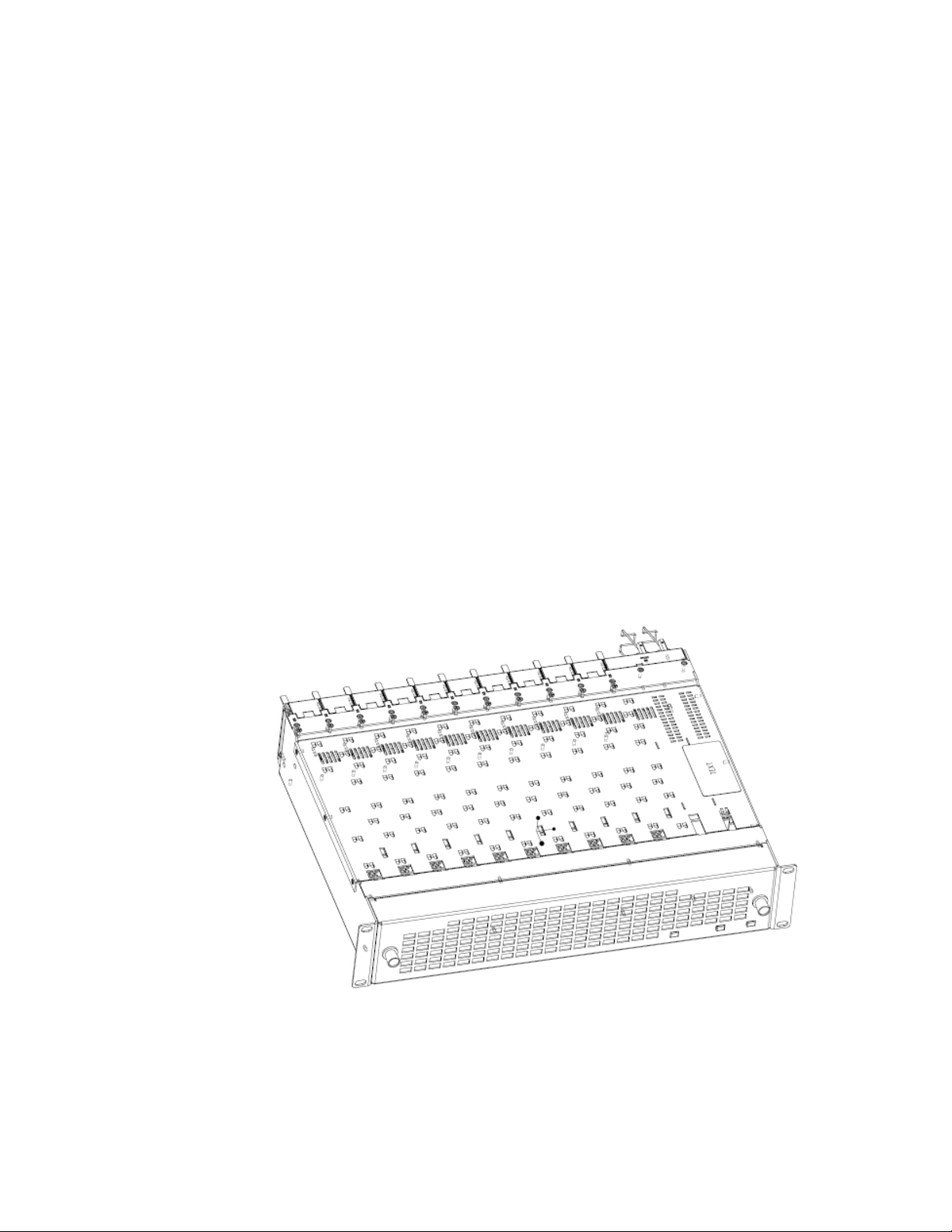
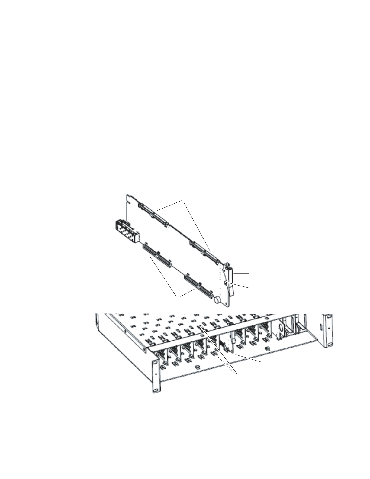
There are ten rear and front slot locations in the 2 RU frame to accommo-
date audio/video modules (Figure 1). The 8925EMB module set may be
plugged into any one of the available GeckoFlex frame slots. The 8925EMB
requires a single rear slot.
Power Up on page 18).
Note Use anti-static precautions when handling the module. As the module can be
changed when the GeckoFlex is powered on, before removing the cover,
please put an anti-static bracelet tied to a metal part of the frame.
Figure 1. GeckoFlex Frame
10 8925EMB-B and -U — Instruction Manual
Page 11

Module Installation Precautions
Please read and follow the precautions listed below before installing the
front and rear modules, and any optional fiber optic SFP devices:
• Use standard anti-static procedures during installation. As modules
can be installed or removed when the GeckoFlex frame is powered up,
before removing the cover, please use an anti-static bracelet or heel
strap tied to a metal part of the frame.
• Install the rear module first, then the front module, then the optional
optical SFP device (if used).
• When installing or removing a rear module, loosen or tighten the
screws holding the retainer clips to the frame manually with the
retainer clip tool provided inside the front cover of the frame or use a
2 mm (5/64”) hex screwdriver. Please do not use an electric screwdriver.
Note On newer 751- version GeckoFlex frames, a Rear Retainer Clip removal tool
and 2 extra retainer clips and screws for installing them are provided on the
inside of the frame cover.
Installation
• Make every effort to leave the screws holding the retainer clips in place
(do not remove them completely). They are very small and can easily
drop into other equipment causing a shorting hazard. (Two turns of the
screw should be enough to loosen the screws, 3 turns or more will
remove it.)
• When installing a rear module, tighten the screws on the retainer clips
just until snug. Do not apply more force than is necessary to seat the
rear module. Do not use an electric screwdriver. Refer to the rear
retainer screw torque specification in the
page 54.
• If using a fiber optic SFP device, handle it carefully, use anti-static precautions, and read the Fiber Optic Cleaning Requirement on page 14
before cabling.
Mechanical section of Tab le 5 on
8925EMB-B and -U — Instruction Manual 11
Page 12
Installation
Rear Module Installation
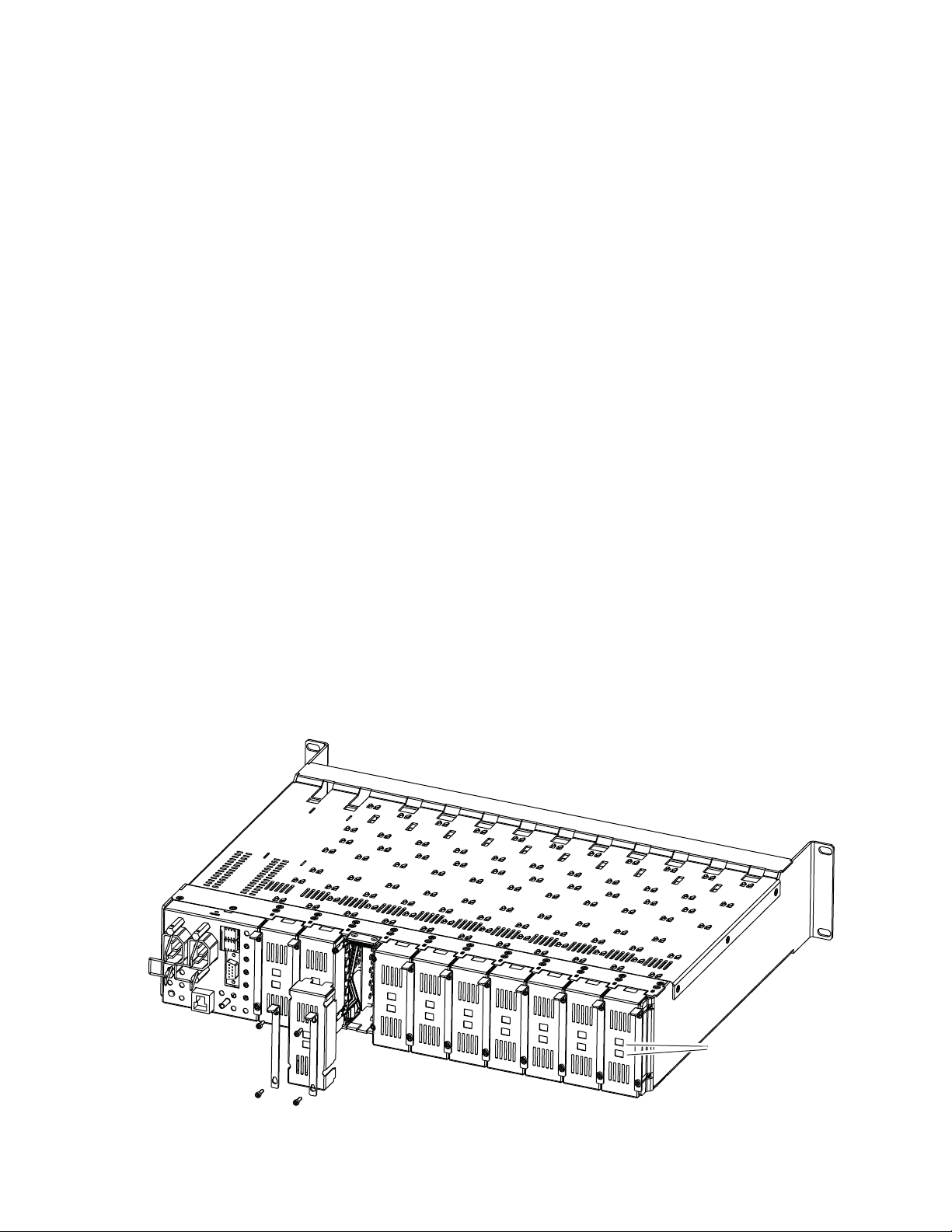
To install the rear module, refer to Figure 2 and the instructions below:
1. To remove a blank rear adapter cover (or a rear module already
present), manually loosen the two screws holding each retainer clip on
the rear adapter cover or rear module to the frame with the retainer clip
tool provided inside the front cover of the frame (newer model frames
only) or a 2 mm (5/64”) hex screwdriver. Do not remove the screws.
Note To remove a rear module already installed, follow the same steps. It is helpful
to first remove the front module so the rear can be pulled out more easily.
2. After loosening the retainer clip screws, pull up on each retainer and
completely remove it, leaving the screws in place.
3. Remove the blank rear adapter cover by inserting needlenose pliers
into the slots in the blank cover and pulling it off.
4. Insert the rear module into the empty slot, guiding it carefully.
5. Replace each retainer clip over the two screws on both sides of the
module and push down to seat the retainer clip.
6. Tighten the two screws on each retainer clip just until they come into
contract with the retainer clip then tighten about a 1/4 turn more
(maximum torque is 4-5 inch-lb/0.45-0.6Nm). Do not force or torque
the screws too tightly. The clips should not bend or be bowed.
Note All unused rear slots in a GeckoFlex frame should have a blank rear adapter
cover installed.
Figure 2. Installing Rear Module (751- Version Frame)
8444_23r0
Use retainer clip or
needlenose pliers
to pull out blank after
removing retainer clips
12 8925EMB-B and -U — Instruction Manual
Page 13
Front Module Installation
8479_03
Slide top and bottom card carriers on module
over top and bottom guides on right of slot.
Module installed
Locking Pin
Card Carriers
Card Carriers
Front Module Side View
Ejector Tab
Note Before installing the front module, the rear module must be installed.
Also refer to the Optional Fiber Optic SFP Device Installation on page 14 if the
fiber optic SFP device is present.
After installing the rear module, install the front module as follows:
1. Unlatch and remove the front cover.
2. Insert the front module in the guides of the corresponding slot as
shown in Figure 3.
3. When installed properly, the module ejector tab should be locked in its
locking pin.
Note Before extracting the front module, extract the fiber optic SFP device and its
cable first from the fiber optic cage on the rear of the frame.
Figure 3. Front Module Installation
Installation
8925EMB-B and -U — Instruction Manual 13
Page 14

Installation
Optional Fiber Optic SFP Device Installation
After the front and rear modules have been installed, install the fiber optic
SFP device if being used into the rear module metal cage labeled FIBER
(
Figure 4 on page 15). The SFP device is hot-pluggable and may be installed
or removed with power applied to the module.
CAUTION Use anti-static precautions and handle the SFP device carefully when
installing and the removing it.
to clean all fiber connections as described in Fiber Optic Cleaning Require-
ment below.
Refer to Tab le 1 for the correct model of SFP device to use with different
software versions.
Table 1. Fiber Optic SFP Device Summary
SFP Device Type SW 2.1.3 and later SW 2.1.3 and earlier
SFP-13103G-M1DRX Dual Receiver X –
SFP-13103G-M1DTX Dual Transmitter X –
SFP-13103G-M1TRX Transceiver X –
1310nm-DRL Dual Receiver X X
1310nm-DTL Dual Transmitter X X
1310nm-TRL Transceiver X X
Before inserting the fiber cable, it is important
Fiber Optic Cleaning Requirement
Before making any fiber optic cable mating connections, including installation, and after every de-mating cycle, use an industry standard fiber optic
cleaning kit, including oil-free compressed air, to clean the fiber connectors
and the connectorized fiber end faces. This helps ensure optimum perfor
mance of the fiber optic interface. Industry standard fiber optic cleaning
kits can be purchased on the web and in electronics stores.
-
14 8925EMB-B and -U — Instruction Manual
Page 15
Installation
FIBER
J7J9J8
8431_03r2
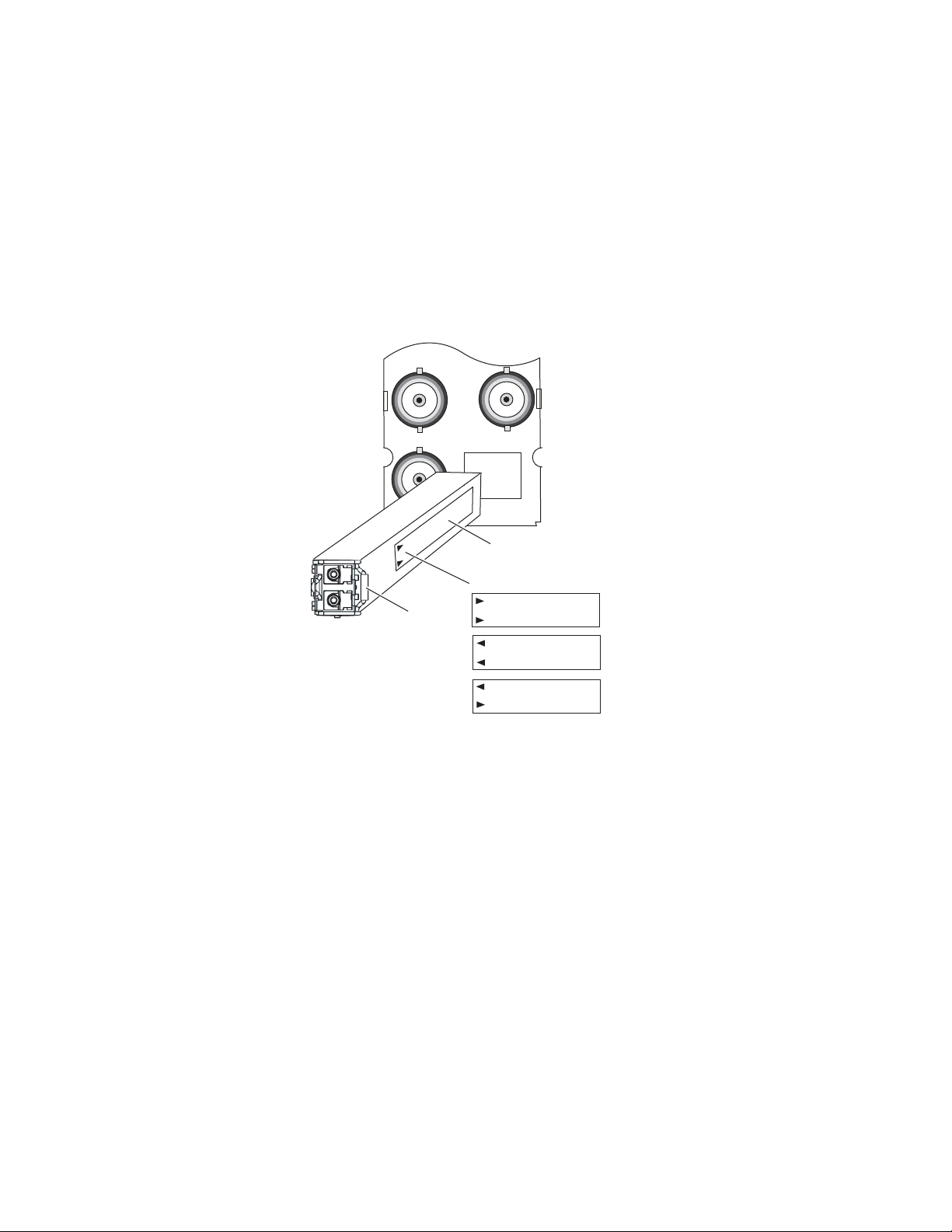
Label
Handle
Arrow Indicators:
Dual Receiver
Dual Transmitter
Transceiver
To install the fiber optic SFP device:
1. Slide the fiber optic SFP device into the cage connector connected to the
front module at the rear of the frame (label on right. See Figure 4.
2. When installed properly, the front end of the SFP device will line up
with the rear module BNCs. Do not try to force it in further.
3. Cable the fiber optic connectors according to the instructions given in
Cabling on page 16 depending on the type of SFP device used.
Figure 4. Fiber Optic SFP Device
To extract the fiber optic SFP device follow the steps below:
1. Remove the fiber cable first.
2. Unlock the module by flipping the handle to the left.
3. Remove the fiber optic SFP device by using its handle.
8925EMB-B and -U — Instruction Manual 15
Page 16

Cabling
Cabling
Cabling to the 8925EMB-B or 8925EMB-U module is done on the
8900BVF-R rear module (balanced audio inputs) or the 8900UVF-R rear
module (unbalanced audio inputs).
The I/O Config web page shows the inputs and the outputs assigned to the
different connectors of the rear modules. Cabling of the rear module
depends on what optional fiber optic SFP device is installed as below:
• 8925EMB-B and 8925EMB-U without optional fiber optic SFP device
(electrical only),
• 8925EMB-B and 8925EMB-U with SFP-13103G-M1DRX, Dual Receiver
Fiber Optic SFP device
• 8925EMB-B and 8925EMB-U with SFP-13103G-M1DTX, Dual Transmitter Fiber Optic SFP device, and
• 8925EMB-B and 8925EMB-U with SFP-13103G-M1TRX, Transceiver
Fiber Optic SFP device.
The 8925EMB-B and the 8925EMB-U will accept any of the video standards
listed in the input specifications in
Ta bl e 5 on page 54. Configure the stan-
dards accepted by the module on the System Config Web Page on page 31.
Ta bl e 2 below gives the inputs and the possible video output connections
for the 8925EMB rear modules. The cabling is illustrated in Figure 5 on
page 17 for the 8900BVF-R rear module and Figure 6 on page 17 for the
8900UVF-R rear module.
Table 2. 8925EMB Rear Cabling
Option
Without optical option J9 J1, J2, J3, J4 J5, J6, J8 J7 N/A N/A
With Dual Receiver J9 J1, J2, J3, J4 J5, J6, J8 J7 Fiber 1 or Fiber 2 N/A
With Dual Transmitter J9 J1, J2, J3, J4 J5, J6, J8 J7 N/A Fiber 1 and Fiber 2
With Transceiver J9 J1, J2, J3, J4 J5, J6, J8 J7 Fiber 1 Fiber 2
Video Inputs
Coax
Audio Inputs Video Outputs
Reclocked Video
Output
Optical Inputs Optical Outputs
16 8925EMB-B and -U — Instruction Manual
Page 17
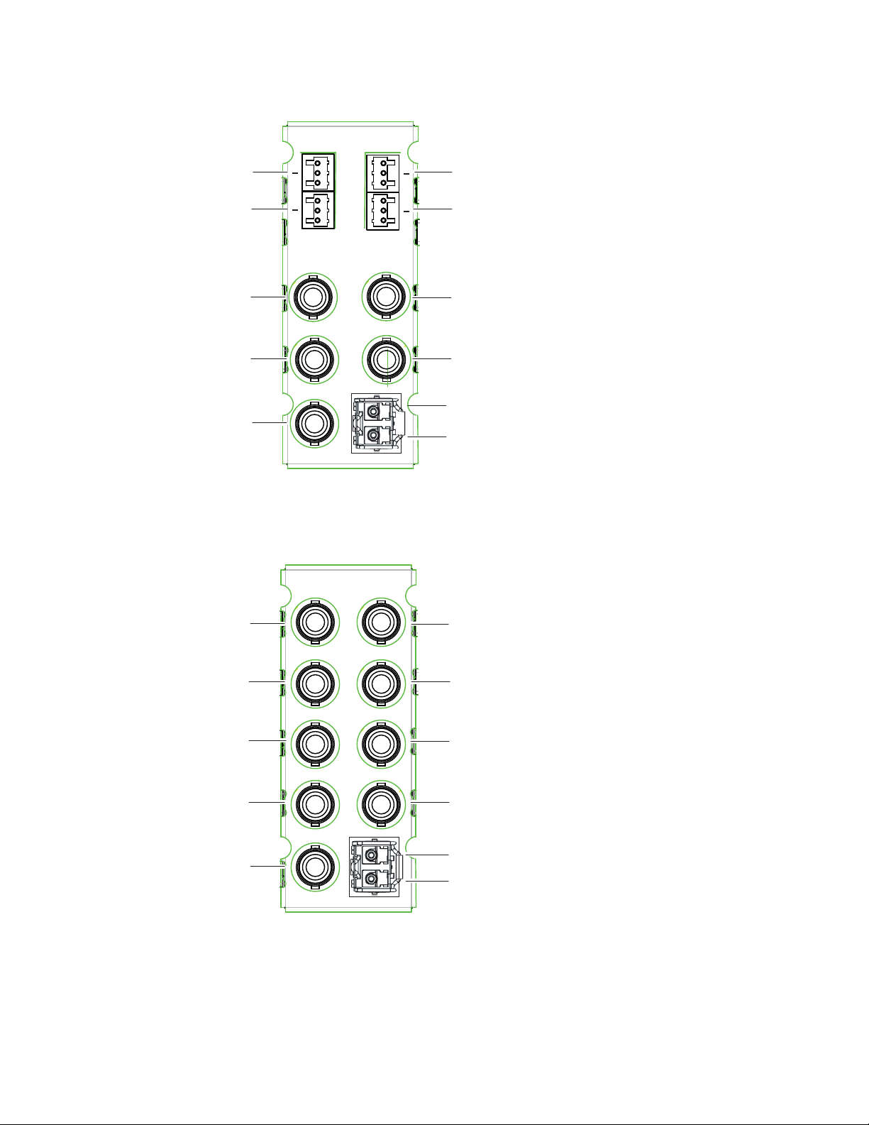
Figure 5. 8900BVF-R Rear Module
8900BVF-R
SD/HD
SDI In
SD/HD
SDI Out
SD/HD
SDI Out
(reclocked)
SD/HD
SDI Out
SD/HD
SDI Out
Fiber 2 In/Out
J1
J2
J4
J9
J7
J5 J6
J8
J3
Fiber 1 In/Out
8478_10R1
+
G
+
G
+
G
+
G
Audio 1
Input
Audio 3
Input
Audio 2
Input
Audio 4
Input
8900UVF-R
SD/HD
SDI In
SD/HD
SDI Out
SD/HD
SDI Out
(reclocked)
SD/HD
SDI Out
SD/HD
SDI Out
Fiber 2 In/Out
Fiber 1 In/Out
8478_11r1
Audio 1
Input
Audio 2
Input
Audio 4
Input
Audio 3
Input
J1
J3
J5
J7J9J8
J6
J4
J2
Cabling
Figure 6. 8900UVF-R Rear Module
8925EMB-B and -U — Instruction Manual 17
Page 18
Power Up
Power Up
Operation Indicator LEDs
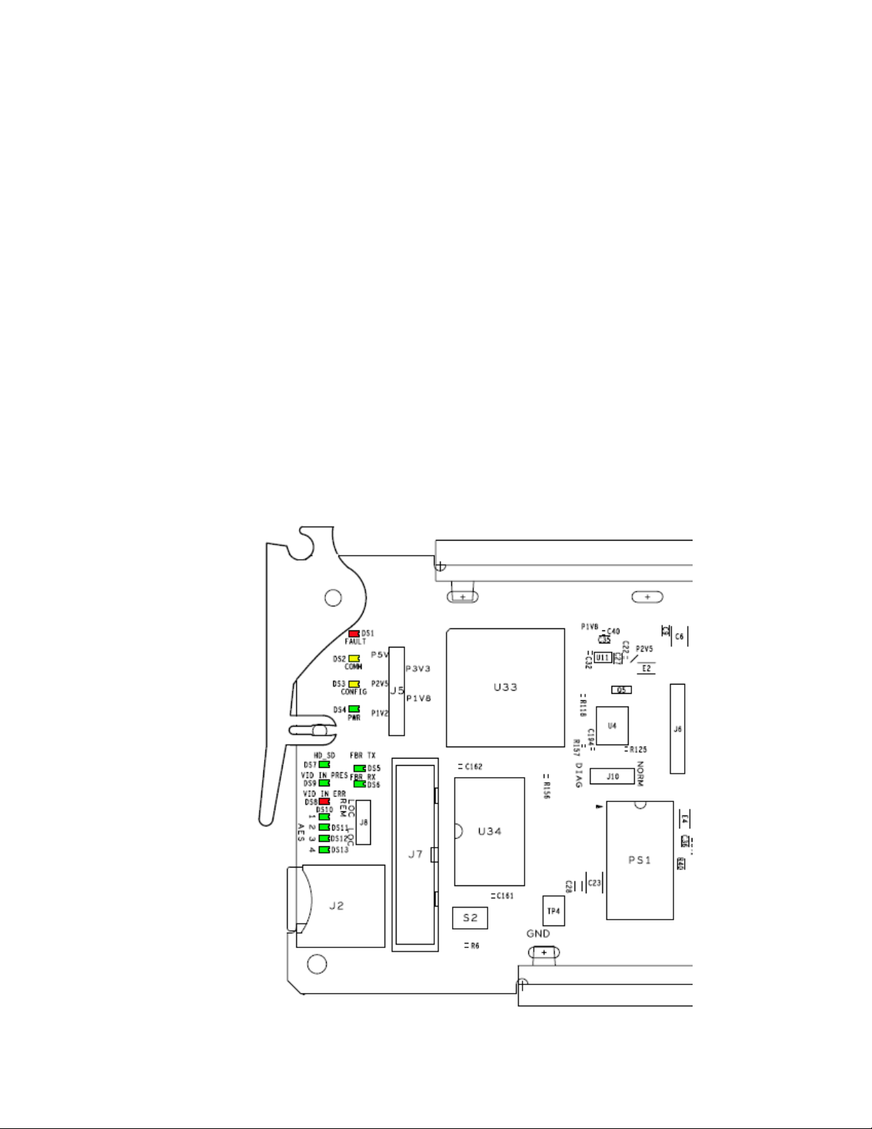
The on-board LED indicators are illustrated in Figure 7. Upon power-up,
the green PWR LED should be on. The CONFIG and FAULT LEDs should
briefly light on and the COMM LED should blink during the module ini
tialization.
Note When a module is first plugged into a GeckoFlex frame, the 8900NET module
(if present) may report a momentary fault. This will clear once the module has
booted up.
With a valid input signal is connected, the VID IN PRES LED should be on.
Refer to
ditions and the resulting indicator status.
Note LED colors are highlighted in Figure 7 for reference only. They are not
Ta bl e 3 on page 19 to see a complete list of possible operating con-
intended to show the state of the module at power up.
-
Figure 7. Front LEDs Indicators
18 8925EMB-B and -U — Instruction Manual
Page 19

A continuous FAULT LED on (red) indicates an error situation and, when
noted with the other indicator LEDs, can indicate a specific problem area.
Ta bl e 3 describes signal output and LED indications for the various
input/reference combinations.
Table 3. LED Indicators
LED Indication Condition
FAULT
(red)
COMM
(yellow)
CONFIG
(yellow)
PWR
(green)
AES 1
(green)
AES 2
(green)
AES 3
(green)
AES 4
(green)
HD_SD
(green)
VID IN PRES
(green)
VID IN ERR
(red)
FBR TX
(green)
FBR RX
(green)
Off Normal operation
On continuously Module has detected internal fault.
Long flash Presence of reported warnings
Off No activity on frame communication bus
Long flash Location Module command received by the module from a remote control system
Short flash Activity present on the frame communication bus
Off Module is in normal operating mode
On continuously Module is initializing, changing operating modes or updating firmware
Long Flash Synchronous with COMM led when executing Locate Module command
Off No power to module
On continuously Normal operation, module is powered
Off No AES1 input presence
On AES 1 input presence
Off No AES 2 input presence
On AES 2 input presence
Off No AES 3 input presence
On AES 3 input presence
Off No AES 4 input presence
On AES 4 input presence
Off Indicates the video input rate SD
On Indicates the video input rate HD
Off No presence of signal
On Presence of the signal
Off Normal video input
On Video input error, unknown or format mismatch
Off Indicates the video optical fiber output is disabled
On Indicates the video optical fiber output is enabled and an SFP device is present
Off Indicates the video optical fiber input is disabled
On Indicates the video optical fiber input is enabled and an SFP device is present
Power Up
8925EMB-B and -U — Instruction Manual 19
Page 20

Remote Configuration
Remote Configuration
The 8925EMB-B and 8925EMB-U configuration and monitoring must be
performed using a web browser GUI interface or a networked Newton
Control Panel with an 8900NET Network Interface module with software
version 4.3.0 or later present in the GeckoFlex frame (8900FFN). Each of
these interfaces is described below. A summary table of all module param
eters including defaults, ranges, and Newton Control panel controls is
given in
8900NET Module Information
Refer to the 8900NET Network Interface Module Instruction Manual (software
version 4.3.0) for information on the 8900NET Network Interface Module
and setting up and operating the GeckoFlex 8900 frame network. This
manual, along with the latest 8900NET Release Notes can be found at the
link below:
http://www.grassvalley,com/docs/modular
Tab le 13 on page 61.
-
Newton Control Panel Configuration
A Newton Control Panel (hard or soft version) can be interfaced to the
GeckoFlex frame over the local network. Refer to the documentation that
accompanies the Newton Modular Control System for installation, config
uration, and operation information.
Control panel access offers the following considerations for module configuration and monitoring:
• Ability to separate system level tasks from operation ones, minimizing
the potential for on-air mistakes.
• Ability to group modular products—regardless of their physical locations—into logical groups (channels) that you can easily manipulate
with user-configured knobs.
• Recommended for real-time control of module configuration parameters, providing the fastest response time.
Note Not all module functions are available with the control panel, such as factory
default recalls.
-
20 8925EMB-B and -U — Instruction Manual
Page 21
Remote Configuration
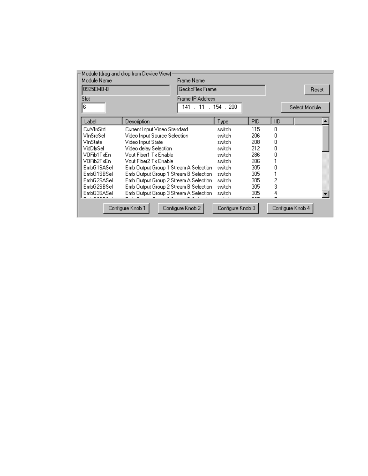
An example of the Newton Configurator is shown in Figure 8.
Figure 8. Newton Configurator Example
Web Browser Interface
The web browser interface provides a graphical representation of module
configuration and monitoring.
Use of the web interface offers the following considerations (some functions depend on individual module functionality):
• Provides complete access to all module status and configuration func-
tions, including naming of inputs and outputs, factory parameter and
name default recalls, Save/Load module configuration functions, slot
configurations, and SNMP monitoring controls.
• Web access will require some normal network time delays for pro-
cessing of information.
• Configuration parameter changes may require pressing
Enter, upload processing time. A manual screen refresh is recommended
after changing parameters.
• Web interface recommended for setting up module signal and slot
names, and reporting status for SNMP and monitoring.
Refer to the Status web page shown in Figure 9 on page 22. The 8900
modules can be addressed by clicking either on a specific module icon in
the frame status display or on a module name or slot number in the link list
on the left.
Apply button or
8925EMB-B and -U — Instruction Manual 21
Page 22

Remote Configuration
8480_02r0
The Links section lists the frame and its current modules. The selected link's Status
page is first displayed and the sub-list of links for the selection is opened. The sub-list
allows you to select a particular information page for the selected device.
Content display section
displays the information page
for the selected frame or module (frame slot icons are also
active links).
Refresh button for manual
update of page
Note The physical appearance of the graphics on the web pages shown in this
manual represent the use of a particular platform, browser and version of
8900NET module software. They are provided for reference only. Web pages
will differ depending on the type of platform and browser you are using and
the version of the 8900NET software installed in your system. This manual
reflects an 8900NET module with software version 4.3.0, using Internet
Explorer, the recommended web browser, and Windows XP operating
system.
For information on status, fault monitoring and reporting shown on the
module Status web page, refer to
Figure 9. Frame Status Web Page
Status Web Page on page 26.
22 8925EMB-B and -U — Instruction Manual
Page 23

Pulldown Menus
Button
Radio button
Check box
Refresh button
Coarse Adjust
Fine Adjust
Enter
Low Limit
Status Indicator
Entry Field
Web Page Operations and Functional Elements
The following conventions and functional elements (shown at left) are used
in GeckoFlex web page operations. (The examples shown throughout this
manual represent 8900NET software version 4.3.0):
• Pulldown menus allow you to choose selections from a list.
• Clicking on a button performs an immediate action such as recall of
defaults, clearing of states, learning configurations, and selecting all or
none of a selection.
• Radio buttons are used to make a choice of one parameter in a group.
• Check boxes are used when a selection can be enabled or included in a
group. Multiple check box selections or enables can be made for some
parameters.
Refresh button (circular arrow) is provided at the top of each web page
•A
for manual refresh to view recently changed parameters.
• Each numerical adjustment control has a
right top double arrows) which increases or decreases the step value by
High Limit
a factor of 10. The
increases or decreases the step value by 1.
To change a value, use the arrow button controls or enter a value into
the number field and select the
your keyboard. The Status Indicator bar will follow the value selected.
Fine adjust button (left and right inside single arrows)
Enter button (*) or use the Enter key on
Remote Configuration
Coarse adjust button (left and
Status LED
Use the Low and High Limit buttons to go directly to the lowest and
highest limits for the parameter.
8341_13
After a parameter has been changed, it will take approximately 10
seconds for the change to be entered into the module backup memory.
Allow the module enough time to update the change before removing
the module from its slot.
• An entry field allows naming of various module functions such as
input or output signals, asset tag, and slot identification.
•The
Status LED icon indicates module status and is a link to the module
Status web page where status is reported.
LED colors indicate:
• Green = Pass – no problems detected
• Yellow = Configuration error warning
• Red = Fault condition detected (presence of at least one alarm)
8925EMB-B and -U — Instruction Manual 23
Page 24

Remote Configuration
Web Page Headers
Each configuration web page has a Status and Identification Header as
shown in Figure 10 below.
Figure 10. Web Page Header
The header information on each web page includes the following:
• Model and Description are read-only generated by the module.
Frame Location is defined on the 8900 Series GeckoFlex frame configura-
•
tion web page.
Slot number reports the module’s location in the frame.
•
Input Video Standard reports the input video type and rate detected by the
•
module.
•
Input Video reports the status of the video input to the module.
Fiber Module Type reports (on the Status, I/O Config, Video Input, and
•
Video Output web pages) the status or type of the fiber optic SFP device
with one of the following four messages:
• Not Installed,
• RX/TX, 1310 nm,
•Dual RX, or
• Dual TX, 1310/1310 nm.
Web pages with configuration param
bottom of the page to allow resetting of
page. Default values for all parameters are listed in Tab le 13 on page 61.
eters each have a Defaults button at the
default parameters for only that
24 8925EMB-B and -U — Instruction Manual
Page 25

8925EMB-B and 8925EMB-U Links and Web Pages
The web interface 8900 GUI provides the following links and web pages for
the 8925EMB-B and 8925EMB-U modules (shown at left):
• Status web page – reports input and output signal status, frame bus
communicat
errors (page 26),
• I/O Config web page – shows the presence of the signals on a specific
connector, allows naming of each input and enables or disables the
signal reporting (page 29),
• System Config web page – set input video rate and line standards to be
accepted by the module (page 31),
• Video Input web page – allows selection of the video input source (coax
or fiber) and provides the status of all sources, including optional fiber
optic SFP devices inputs, indicates status of the audio available for
embedding, and provides a Video Delay control for minimizing video
delay or offset in relation to the embedded audio (page 33),
ion status, module status and information, warnings and
Remote Configuration
• Audio Input web page – reports the audio input status of the audio
sources to the module and provides a Low Delay control used in conjunction with the Video Delay controls to improve audio quality and an
Audio Input Warnings section allowing individual muting of each of
the four AES audio streams based on the type of warning or error condition being reported (page 37),
• Audio Embedder web page – lists the audio streams and their status
available for embedding into the four audio groups in the video output
signal and allows selection of bit rate for each audio stream (page 40),
• Video Output web page – enables/disables the fiber optic video output
when a fiber optic SFP device is installed (page 42),
• User Settings web page – allows recalling of factory defaults for all
module parameters or factory signal names and provides a save/load
configuration file function (page 43),
• Slot Config web page – provides Locate Module, Slot Identification,
and Slot Memory functions along with links to the SNMP, LED
Reporting, and Frame Alarm configuration 8900NET web pages
(page 46).
A summary table of all module paramete
Newton Control panel controls is given in Tab le 13 on page 61.
rs including defaults, ranges, and
8925EMB-B and -U — Instruction Manual 25
Page 26

Remote Configuration
Use
this
link
Status Web Page
The Status web page (Figure 11 on page 28) reports information and status
about the front media and rear modules and any SFP devices present (if
licable for the module) in both graphical (using color to indicate status)
app
and textual formats. It also reports the status of the input and reference
video signals to the module and SFP devices, and the Frame Bus status.
Video and reference signal reporting can be enabled and disabled at the
module level on the I/O Config web page (page 29).
In general, graphics and text colors us
lowing:
• Green = Pass – signal or reference present, no problems detected.
Red = Fault – fault condition.
•
• Yellow = Warning – signal is absent, has errors, or is mis-configured.
• Gray = Not monitored.
Note Always refresh the page first with the Refresh button at the top of the page
(shown at left) to update the current status of the web page.
ed for status indication are the fol-
Web Page Header
The content of the web page header for the module is described in detail in
Web Page Header on
page 26.
Module Physical Structure
Status is reported for the front, rear, and optional fiber optic SFP devices as
follows:
• Rear Module – the presence, name, an
module is reported in the graphic on the left. If the rear module is the
wrong type or missing, the graphic will indicate the status by color and
text within the graphic.
d internal status of the rear
• Front Processing Module – the presence, name, and internal status of
the front processing module is reported in the graphic on the right. The
graphic will indicate the status of the front module by color and text
within the graphic.
• Fiber Module – the optional fiber optic SFP device status will be shown
in the box on the front module graphic. When a fiber optic SFP device
is installed, the type will be reported in the top header and the Status
text below the graphic on the right.
26 8925EMB-B and -U — Instruction Manual
Page 27

Remote Configuration
Status is reported for each of the following audio and video signals:
• Video inputs indicate the status of the video inputs incoming on the
BNC connectors, one of two possible fiber optic inputs (depending on
the type of the fiber optic SFP device installed),
• Video outputs are always gray as the outputs are not monitored,
• Audio inputs indicate the status of the audio inputs,
• Frame bus indicates the status of the communication bus to the
8900NET module, and
• Fiber module shows if a fiber module is installed. When not installed,
the graphic will be white and report
Note On the 8925EMB modules, input signals are represented by up to five input
signal arrows.
Fiber Module not Installed.
Warning/Fault/Message Reporting
Faults, warnings, and informational messages from the module are displayed between the double bars below the graphic.
Module Status
Module status for the front and rear modules (and any SFP devices if applicable) are reported as PASS, WARNING, ERROR, or EMPTY on the right at
the bottom of the display.
Front Module Information
Information about the module, such as part number, serial number, hardware revision and software, firmware, and boot versions, and asset tag
number (assigned on the
left at the bottom of the display.
Slot Config Web Page on page 46) are given on the
8925EMB-B and -U — Instruction Manual 27
Page 28

Remote Configuration
summary section
Warning and Fault
Figure 11 illustrates the inputs and outputs on an 8925EMB-U module.
Figure 11. Status Web Page for 8925EMB-U Module
28 8925EMB-B and -U — Instruction Manual
Page 29

I/O Config Web Page
Use
this
link
Use the I/O Config web page (Figure 12 for the 8900UVF-R rear module
and Figure 13 on page 30 for the 8900BVF-R rear module) for the following:
8900UVF-R Rear Module Configuration
All of the input and output connectors on the corresponding 8925EMB-B or
8925EMB-U rear module are illustrated on the I/O Config web page. The
inputs can be configured with the following controls:
Signal Names – type of the desired input name (up to 12 characters) into
•
the corresponding boxes for each input. The status of each input is indicated by the color of the display. The color legend is under the table.
Note The status color yellow can also indicate that the input is invalid.
• Reporting – the status reporting of the input can be enabled or disabled
at the module level by selecting or deselecting the corresponding
checkbox in the
Remote Configuration
Reporting column for each input.
Figure 12. I/O Config Web Page – 8900UVF Rear
Note The outputs are not monitored in this application.
8925EMB-B and -U — Instruction Manual 29
Page 30

Remote Configuration
Figure 13. I/O Config Web Page – 8900BVF Rear
30 8925EMB-B and -U — Instruction Manual
Page 31

System Config Web Page
Use
this
link
Use the System Config web page (Figure 14 on page 32) to set the video
input standards accepted by the module.
Input Standard Selection
Select any of the following input standards to be accepted by the module:
• HD 1080i/59.94,
HD 1080i/50,
•
• HD 1080p/23.98,
• HD 1080sf/23.98,
• HD 720p/59.94,
• HD 720p/50,
• SD 480i/59.94, and
• SD 576i/50.
Remote Configuration
When a video format is input to the m
detected. If the standard matches the user selection it will be declared as
valid or it will generate an
Invalid Format error.
odule it will be automatically
Defaults Button
Select the Defaults button to restore the default setting (all standards
selected).
8925EMB-B and -U — Instruction Manual 31
Page 32

Remote Configuration
Figure 14. System Config Web Page
32 8925EMB-B and -U — Instruction Manual
Page 33

Video Input Web Page
Use
this
link
Use the Video Input web page (Figure 15 on page 35) to select and monitor
the video input source to the module with the following:
Video Input Selection
This section provides the following for the video input signal:
Select Input Video – select the input source from the rear module as one of
•
the following input sources. Only one source can be enabled at a time.
•
Coax – select the electrical input at BNC J9 as the video input.
Fiber RX1 – check the Enabled checkbox to enable the Fiber RX1 input
•
as the input video (SFP-13103G-M1DRX or SFP-13103G-M1TRX
SFP device must be installed).
Fiber RX2 – check the Enabled checkbox to enable the output
•
(SFP-13103G-M1DRX SFP device must be installed).
•
Signal Name – the signal name defined on the I/O Config web page will
appear in this field.
Remote Configuration
Signal State – this field reports the status of the input video signal as
•
Present, Not Present, Not Supported (in the case of no fiber SFP device
installed) or Invalid format.
Video Delay
Controls are provided for two different settings to accommodate the additional electrical length of audio process
one of the following according to the type of audio and the delay requirements of the video:
Minimize Video Delay – checking this box enables a mode that bypasses an
•
internal video delay that is meant to match the AES input audio delay
when bypassing the Sample Rate Converter (SRC). This box should
normally be unchecked because audio/video delay matching is more
important than minimizing video delay in most cases.
When the shortest video delay is the most important criteria for the
mod
ule, use this setting. As the audio embedding processing has a
longer electrical length than the video delay, the module produces an
audio/video offset, especially when Audio Sample Rate Conversion is
enabled with non-synchronous audio. This mode is not recommended
for Dolby E signals.
ing. Set the Video delay control to
When in this mode, the video electrical length of the module will be the
ific length as reported in Tab le 9 on page 57.
spec
8925EMB-B and -U — Instruction Manual 33
Page 34

Remote Configuration
• Minimize Audio/Video Offset – checking this box enables a mode that adds
an internal video delay that matches the delay when bypassing the
SRC. When non PCM audio is detected on some of the AES input channels, the SRC’s for those channels are automatically bypassed. If
Delay
is selected on all channels, all SRC’s are forcibly bypassed and the
video delay matches the audio delay.
Refer to Tab le 9 on page 57 for specific lengths when using this mode.
This mode is most usefu l when the Sample Rate C onversion on the AES
input is bypassed which happens automatically when embedding a
Non-PCM (such as Dolby
This mode should be used when handling Dolby
Use this mode in conjunction with the Low Delay control for Sync PCM
audio on the Audio Input web page (
to reduce the audio processing delay (and audio/video offset).
E) audio stream synchronous with the video.
E streams.
Audio Input Web Page on page 37)
Low
34 8925EMB-B and -U — Instruction Manual
Page 35

Figure 15. Video Input Web Page
Remote Configuration
8925EMB-B and -U — Instruction Manual 35
Page 36

Remote Configuration
Embedded Audio Status
This section gives the name and the state of the incoming embedded audio
streams.
• Input Stream Name – name entered in the I/O Config web page with the
extension which indicates the group and the stream number (for
example Coax In.G1.S2 means Stream 2 of the Group 1),
Signal State – indicates the incoming embedded audio streams presence,
•
Sample Rate – indicates the frequency of the audio,
•
Mode – means the maximum audio resolution which can be 20 or 24 bits.
•
It is only indicated in SD format.
Defaults Button
Select the Defaults button to restore the default Video Input Source (Coax)
and Video Delay (Minimize Video Delay).
36 8925EMB-B and -U — Instruction Manual
Page 37

Audio Input Web Page
Use
this
link
Use the Audio Input web page (Figure 16 on page 39) to select and monitor
the audio input status of the external audio s
are also provided for enabling or disabling muting of each individual audio
stream based on certain error criteria.
Audio Input Status
This section provides the following status monitoring fields for the audio
inputs:
Stream Name – reports the name defined for the audio streams on the I/O
•
Config web page.
•
Stream State – this field reports the presence of the audio stream as
Present or Not Present (indicating not present or not valid).
Sample Rate – this field reports the sample rate of the audio stream.
•
Mode – reports if the audio stream is 20 bit or 24 bit.
•
Audio Mode Source – this field reports if the audio stream is a PCM or
•
Non-Audio signal.
Remote Configuration
ources to the module. Controls
Sync PCM, Low Delay – the Low Delay control can be enabled to further
•
reduce the audio processing delay (and audio/video offset) when an
audio input is fully synchronous to the video and has a 48kHz Sample
Rate. Using this control will improve audio quality since the Sample
Rate Converter is bypassed in this state.
When this control is used in conjunction with the
Minimize
Audio/Video Offset control on the Video Input web page (Video Input
Web Page on page 33) it is possible to maintain the audio/video delay
close to its initial delay.
AES Errors Detected – when AES errors are detected on the incoming audio
•
stream, an
stream. Use the
Errors message will be reported in red for the affected audio
Reset button to reset the audio error log.
The audio stream may be muted depending on the settings made in the
Audio Input Warnings section as shown in Figure 16 on page 39. The
8925EMB mutes the audio stream when err
ors are detected to reduce as
much as possible, embedding distorted audio data that may be audible.
When an AES signal stream is not detected or when errors are detected
d the audio is muted, an alarm will be also raised on the Status web
an
page
(Audio Input X: Signal Not Detected {or Not Valid}).
8925EMB-B and -U — Instruction Manual 37
Page 38

Remote Configuration
Audio Input Warnings
The Audio Input Warning controls allow the user to define audio muting for the
four AES audio input streams for each type of audio warning detected by
the module. When an audio warning is detected and muting is enabled for
that condition, the module will mute audio streams 1-4 and an error will be
logged into the AES Errors Detected section of the Audio Input web page
(
Figure 16 on page 39).
Note When the Low Delay checkbox is selected for an audio stream in the Audio
Input Status section (SRC bypassed), the auto-mute function is disabled.
Each type of audio warning listed below can be enabled or disabled for
muting audio streams 1-4 when this conditions occur:
• Parity – warning indicates a parity error.
• Bi-phase – warning indicates a coding error in the data stream.
• Valid – warning indicates an invalid video sample.
• Unlock/Block Discontinuity – warning occurs when the phase lock
loop is not locked.
• C-CRC – warning indicates a Cyclic Redundancy Check (CRC) channel
status error.
• Q-CRC – warning indicates a Cyclic Redundancy Check (CRC)
subcode data (digital information data multiplexed with the digital
audio) error.
Many of these warnings occur when the audio is affected by devices
upstream of the audio inputs. This function allows reducing or increasing
sensitivity of the audio error detection to meet the needs of the customer.
The module default condition is muting enabled for Bi-Phase errors only.
38 8925EMB-B and -U — Instruction Manual
Page 39

Figure 16. Audio Input Web Page
Remote Configuration
8925EMB-B and -U — Instruction Manual 39
Page 40

Remote Configuration
Use
this
link
Audio Embedder Web Page
Use the Audio Embedder web page (Figure 17 on page 41) to set the audio
to be embedded into which
Output – gives the name of the audio groups and streams to be processed in
the incoming video signal.
Stream Selection – select one type of processing for each audio Group and
Stream from the choices below.
• Replace with:
udio Input 1,
•A
•Audio Input 2,
•Audio Input 3,
•Audio Input 4, or
• Silence.
•Pass Group
group and stream with the following controls:
• Delete Group
Stream Name – displays the name of the audio stream as defined on the I/O
Config web page or the factory default names.
Resolution – set the pulldown to Auto or force to 20 bit or 24 bit (this control
does not appear when
Processing – reports the audio function performed as Replaced, Passed,
Inserted, or Deleted.
Status – reports the status of the processed audio as Present, Not Present, or
Forced Silence.
Pass Group is selected).
Defaults Button
Select the Defaults button to restore the default Audio Embedder parameters
(Pass Group).
40 8925EMB-B and -U — Instruction Manual
Page 41

Figure 17. Audio Embedder Web Page
Remote Configuration
8925EMB-B and -U — Instruction Manual 41
Page 42

Remote Configuration
Use
this
link
Video Output Web Page
Use the Video Output web page to enable or disable the fiber optic SFP
device outputs when present.
Fiber Video Output
This section allows enabling of the fiber video output signals. Both outputs
can be enabled at the same time.
Fiber TX1 – check the Enabled checkbox to enable the output
•
(SFP-13103G-M1DTX SFP device must be installed).
Fiber TX2 – check the Enabled checkbox to enable the output
•
(SFP-13103G-M1DTX or SFP-13103G-M1TRX SFP device must be
installed).
Defaults Button
Select the Defaults button to restore the default Video Output parameters
(Fiber Outputs disabled).
Figure 18. Video Output Web Page
42 8925EMB-B and -U — Instruction Manual
Page 43

User Settings Web Page
Use
this
link
The User Settings web page (Figure 19) provides a File Operations section
to save/load configuration files to an external location
factory default parameters and signal names for the entire module.
Figure 19. User Setting Web Page
Remote Configuration
and buttons to recall
File Operations
• Save To... – selecting the Save To.. button will bring up the screen shown
in Figure 20. Select
Figure 21 on page 44.
Figure 20. File Download Screen
Save to bring up the Save As screen shown in
In the Save As screen (Figure 21), select or create a directory in which to
store your files. Type in a file nam
tion and select
8925EMB-B and -U — Instruction Manual 43
Save.
e for the current module configura-
Page 44

Remote Configuration
Figure 21. Save As Screen
• Load From... – selecting the Load From... button in the User Settings web
page will bring up the Load Settings web page shown in Figure 22.
Figure 22. Load Settings Web Page
Select the Browse button to bring up the Choose File screen shown in
Figure 23 on page 45 or enter a path and file name into the Enter filename
field.
44 8925EMB-B and -U — Instruction Manual
Page 45

Figure 23. Choose File Screen
Remote Configuration
Click on the file you wish to load and select the Open button. This will
place the file in the Load Settings web page
Select the Load button on the Load Settings web page (Figure 22 on
page 44) to load this file configuration into the module.
Enter filename field.
Set Factory Defaults Button
Select the Set Factory Defaults button to recall factory settings to the entire
module. Refer to the Configuration Summary table on
for a complete list of parameter defaults and ranges.
Tab le 13 on page 61
Set Factory Names Button
Select the Set Factory Names button to recall factory signal names to the
module. Defaults for all signal names are displayed on the I/O Config web
page shown in
Figure 12 on page 29 and Figure 13 on page 30.
8925EMB-B and -U — Instruction Manual 45
Page 46

Remote Configuration
Use
this
link
Slot Config Web Page
Use the Slot Config web page shown in Figure 24 on page 47 to perform the
following functions on the module.
Note This Slot Config web page reflects the use of 8900NET (Net Card) software
version 4.3.0.
Locate Module
Selecting Flash from the Locate Module pulldown flashes the yellow COMM
and CONF LEDs on the front of the module so it can be located in the
frame.
Slot Identification
You may identify the module by typing a specific name in the Name field.
The assigned name is stored on the 8900NET module and travels with the
8900NET module if it is moved to another frame. Select
factory default module name.
Default to enter the
An asset identification may be
entered in the Asset Tag field. This will appear
on the module Status web page and in the NetConfig inventory report.
Slot Memory
The slot configuration for each media module is automatically polled and
refreshed periodically (about every 50 minutes) by the 8900NET module
when the
page (with 4.3.0 software) and/or the
media module Slot Config web page is selected.
When the
web page has been selected, the current configuration from that module is
saved in slot memory on the 8900NET module. This allows the current
module to be removed and when another module of the same part number,
and software version is installed, the configuration saved to the 8900NET
module will be downloaded to the installed module. The
checkbox must be selected before the current module with the saved configuration is removed.
Note Make sure all modules of the same model type are running the same software
Always Slot Refresh checkbox on the 8900NET Configuration web
Restore upon Install checkbox on any
Restore upon Install checkbox on any media module Slot Config
Restore upon Install
version and have the same part number silk-screened on the printed circuit
board. Downloading a configuration to a module with a different software
version or part number can produce unexpected results.
If a different type of module is installed in this slot, a warning message will
state that the original module type has been replaced with another module
type. In this case, a
Clear button will appear allowing you to clear the stored
configuration from the previous module.
46 8925EMB-B and -U — Instruction Manual
Page 47

Remote Configuration
You may also select the Learn Module Config button at any time to save the
current configuration for this slot. The configuration is saved on the
8900NET module. If the 8900NET module is removed or powered down,
the stored configurations are not saved.
When no Restore upon Install checkboxes on any of the media module Slot
Config web pages are selected and the
8900NET Configuration web page is unchecked, the slot refresh polling
function on the 8900NET module will be disabled. See the
checkbox description in the 8900NET (Net Card) Network Interface Module
Instruction Manual for more details.
Note Uncheck the Restore Upon Install button before downloading new software.
Figure 24. Slot Config Web Page
Always Slot Refresh checkbox on the
Always Slot Refresh
8925EMB-B and -U — Instruction Manual 47
Page 48

Software Updating
Frame Health Reporting
This web page allows configuration of the alarms and warnings that are
reported to the external Frame Health Alarm connector on the rear of the
GeckoFlex frame. Refer to 8900NET Instruction Manual for more details.
LED Reports Link
Select the LED Reports link to open the 8900NET LED Reporting web page.
Normally, every module in the frame will report to the 8900NET module
any Fault, Signal Loss, Reference Loss, or Config Error conditions. These
conditions will be reflected by the status LEDs on the 8900NET module.
Using this web page, any of these conditions can be disabled from being
reported to the 8900NET module for each individual module and other
components (power supplies, fans) in the frame
SNMP Trap Reports Link
Select the SNMP Trap Reports link to open the 8900NET SNMP Reporting
web page. This link will only be present when SNMP Agent software has
been installed on the 8900NET module. This web page allows configura
tion of which alarms and warnings that are reported to the SNMP management software.
-
Refer to the 8900NET Instruction Manual for complete details on using the
8900NET web pages.
Software Updating
Software updating of the 8925EMB modules is done using the NetConfig
Networking Application PC option available free of charge from Grass
Valley or the microSD method using a memory card and adapter provided
by the customer.
The procedures for updating software are given in the 8925EMB-B and
8925EMB-U Release Notes when software updates become available. All
modular product documentation can be found in PDF format on the Grass
Valley web site at this link:
www.grassvalley.com/docs/modular
48 8925EMB-B and -U — Instruction Manual
Page 49

Status Monitoring
There are a number of ways to monitor frame and module status. These
methods are summarized here. For more detailed information, refer to the
8900NET (Net Card) Network Interface Module Instruction Manual and the
8900 Gecko or 8900 GeckoFlex Frame Instruction Manuals.
All modular product documentation is available on-line in PDF format at
this link:
www.grassvalley.com/docs/modular
The main status monitoring methods include the following:
• External frame alarm output on the rear of the 8900 frame with
• LEDs on the Frame, 8900NET module, and individual frame media
• Web browser status reporting for each frame component, and
Status Monitoring
reporting from the Module Health Bus and other frame status alarm
reports,
modules,
• SNMP traps, captured by Grass Valley’s NetCentral or another SNMP
Manager Application.
Note SNMP trap information is only available when an SNMP Agent has been
installed and configured.
External Frame Alarm
An external Frame Alarm output is available on pins 8 and 9 of the RS-232
connector on the rear of the frame. The Frame Alarm outputs a voltage
level indicating there is an alarm condition on the Module Health Bus or
one of the other frame components reported to the Frame Monitor module
in a Gecko 8900TF or GeckoFlex 8900FF frame or the 8900NET module in
an 8900TFN and GeckoFlex 8900FFN frame.
• The Module Health bus is a separate line on the frame motherboard
that provides a means for older or less capable modules (such as DAs
with no microprocessor) that cannot communicate over the Frame
(serial) bus to report warning and alarm conditions to the external
Frame Alarm. All media modules in the frame report a voltage level to
this line when a warning condition occurs on the module. The specific
warning or module location is not reported, only an indication that an
warning condition has occurred.
• Frame alarm reporting from other frame components can be enabled
and disabled using DIP switches on the Frame Monitor and 8900NET
module. For frames with an 8900NET module, the Frame Alarm
Reporting web page allows configuration of the alarms and warnings
that are reported to this external Frame Health Alarm.
8925EMB-B and -U — Instruction Manual 49
Page 50

Status Monitoring
LED Reporting
Web Browser Interface
LEDs on the front of media modules, the Frame Monitor or 8900NET modules, and the front covers of the 8900TF/TFN and GeckoFlex FF/FFN
frames indicate status of the frame and the installed power supplies, fans
in the front covers, and module status. (The 8900TX-V/A and GeckoFlex
8900FX frames have no LED indicators on the front cover.)
• LED reporting from the modules in the frame to the 8900NET module
is configurable using the 8900NET LED Reporting web page.
• The Status LEDs for this module are described in Operation Indicator
LEDs on page 18. LEDs for the 8900NET module are described in the
8900NET (Net Card) Network Interface Instruction Manual.
The 8900NET module controls a web browser GUI that indicates frame and
module status on the following web pages:
• Frame Status web page – reports overall frame and module status in
•Module Status web page (Figure 11 on page 28) – shows specific input
• A Status LED icon on each web page reflects the module status on the
SNMP Reporting
The Gecko 8900 Series system uses the Simple Network Monitoring Protocol (SNMP) internet standard for reporting status information to remote
monitoring stations. When SNMP Agent software is installed on the
8900NET module, enabled status reports are sent to an SNMP Manager
such as the Grass Valley’s NetCentral application.
Status reporting for the frame is enabled or disabled with the configuration
DIP switches on the 8900NET module. Most module status reporting items
can be enabled or disabled on individual configuration web pages.
colored graphical and text formats. Refer to Figure 9 on page 22 for an
example.
and reference signal configuration error status to the module along
with module status and information (part number, serial number, hardware version, software/firmware/boot versions, and Asset number (as
assigned on the Slot Config web page).
module Status web page where warnings and faults are displayed and
is a link to the module Status web page.
50 8925EMB-B and -U — Instruction Manual
Page 51

Service
Power-up Diagnostics Failure
Troubleshooting
The 8925EMB modules make extensive use of surface-mount technology
and programmed parts to achieve compact size and adherence to
demanding technical specifications. Circuit modules should not be ser
viced in the field unless otherwise directed by Customer Service.
If the module has not passed self-diagnostics, do not attempt to troubleshoot. Return the unit to Grass Valley (see Module Repair below).
Electronic Circuit Breaker
Service
-
The electronic circuit breaker works during a fault condition or an overcurrent which stops the module.
Remove the module and replace it in the frame. If the problem persists,
please refer to Grass Valley Customer Service.
Module Repair
If the module is still not operating correctly, replace it with a known good
spare and return the faulty module to a designated Grass Valley repair
depot. Call your Grass Valley representative for depot location.
Contacting Grass Valley
If you need to contact Grass Valley for any module issues, refer to Con-
tacting Grass Valley on page 4 at the front of this document for the Grass
Valley Customer Service Information number.
8925EMB-B and -U — Instruction Manual 51
Page 52

Service
Table of Alarms
Ta bl e 3 below describes the different type of alarms reported by the module
to the upper level devices, such as the 8900NET module.
Table 4. Summary of Alarms for 8925EMB-U/-B Module
Alarm
Typ e
Fault Firmware failure On Off Firmware configuration failure Yes
Fault Firmware DCM Not Locked On
Fault
Fault Wrong rear module (incompatible with 8925EMB) On Yes
Fault Fiber module failed, replace On Yes
Fault Power supply failure On Yes
Warning Coax video input signal not detected Flashing Off Yes
Warning Coax video input is invalid or wrong format Flashing On Yes
Warning Fiber 1 video input signal not detected Flashing Off Yes
Warning Fiber 1 video input is invalid or wrong format Flashing On Yes
Warning Fiber 1 video input not supported by hardware Flashing Off
Warning Fiber 2 video input signal not detected Flashing Off Video Input Fiber 2 is selected Yes
Warning Fiber 2 video input is invalid or wrong format Flashing On Yes
Warning Fiber 2 video input not supported by hardware FLASH Off Yes
Warning
Warning Audio Input 1 signal not detected. Flashing
Warning Audio Input 2 signal not detected. Flashing Audio Input 2 Monitored but Not Present Yes
Warning Audio Input 3 signal not detected. Flashing Audio Input 3 Monitored but Not Present Yes
Warning Audio Input 4 signal not detected. Flashing Audio Input 4 Monitored but Not Present Yes
Warning Audio integrity lost, please delete all HANC inputs Flashing
Warning Coax Video Standard does not match with selection Flashing On
Warning Fiber 1 Video Standard does not match with selection Flashing On
Warning Fiber 2 Video Standard does not match with selection Flashing On
Bad firmware image
Hardware configuration does not support selected fiber
video output
Web Page Text Description
FAULT
LED
On
Off Off
VID IN
ERR LED
1
N./A
1
N/A
Comments
Firmware internal system clock failure Yes
A wrong firmware Image has been downloaded
The fiber module does not allow Fiber 1
input
Fiber module is a RX/TX and user chooses
to enable fiber TX1 or fiber is dual RX
Audio Input 1 Monitored but Not Present Yes
User chose to embed a stream without
delete all HANC inputs
Current Coax Video input is not in the
Input Standard Selection table
Current Fiber 1 Video input is not in the
Input Standard Selection table
Current Fiber 2 Video input is not in the
Input Standard Selection table
Status
Reported to
8900Net &
SNMP
Yes
No
Yes
Yes
Yes
Yes
Yes
52 8925EMB-B and -U — Instruction Manual
Page 53

Table 4. Summary of Alarms for 8925EMB-U/-B Module
Alarm
Typ e
Information Fiber module is not installed Off
Information Coax video input signal not detected Off
Information Fiber 1 video input signal not detected Off
Information Fiber 2 video input signal not detected Off
Information Audio Input 1 signal not detected Off
Information Audio Input 2 signal not detected Off
Information Audio Input 3 signal not detected Off
Information Audio Input 4 signal not detected Off
1
N/A: Not Applicable indicates the state of the LED depends on other inputs or internal parameters, it can be On or Off.
Web Page Text Description
FAULT
LED
VID IN
ERR LED
1
N/A
Fiber Input and Output are not selected No
Video coax input not present, but not
selected
Video fiber 1 input not present, but not
selected
Video fiber 2 input not present, but not
selected
Audio Input 1 Not Present, but not Monitored
Audio Input 2 Not Present, but not Monitored
Audio Input 3 Not Present, but not Monitored
Audio Input 4 Not Present, but not Monitored
Comments
Service
Status
Reported to
8900Net &
SNMP
No
No
No
No
No
No
No
Note Please refer to the Operation Indicator LEDs on page 18 and Web Page Oper-
ations and Functional Elements on page 23 for the status and the color of the
LEDs.
8925EMB-B and -U — Instruction Manual 53
Page 54

Specifications
Specifications
Table 5. Main Features
Main Features
SMPTE 274M: SMPTE 296M: SMPTE 259M-C:
HD/SD video format supported by
SMPTE 274M, SMPTE 296M, and
SMPTE 259M-C
Video processing • EDH/CRC insertion, detection and reporting
Embedding processing:
SMPTE 299M
SMPTE 272M Level A, C
SMPTE 337M (no ZCUV bit pass-through)
Audio processing • Sample Rate Conversion
Maximum power consumption 7.7 Watts/642 mA @ +12V
Video delay from input to output
Audio Min. Delay from Input to output
Audio PCM
Audio Min. Delay from Input to Output
Audio Non PCM (Dolby E)
HD/SD Multi-format Auto Detection
Auto sensing and locking time, from loss of
signal or format change to correct signal at
output end
Operational frequency range of HD/SD SDI input Nominal rate ±110 ppm
Mechanical
Frame type GeckoFlex
Number of frame slots required 1 slot
Rear module type
8925EMB-B 8900BVF-R
8925EMB-U 8900UVF-R
Rear module retainer maximum screw torque 4-5 inch-lb./0.45-0.6Nm
1080i/59.94 720p/59.94 480i/59.94
1080i/50 720p/50 576i/50
1080p/23.98
1080sF/23.98
• Video Input Status including incoming embedded audio status
• Video Standard Selection
• Up to four selectable audio groups
• 48 kHz support
• 20 or 24 bit mode or Auto mode
• Auto control packet insertion
• 32 to 96 kHz input rate to 48 kHz output rate
• Synchronous 48 kHz Non PCM format supported (SRC bypass)
• Automatic Dolby E detection and low A/V delay pass-through
• AES input status (presence, error, rate, audio/non-audio)
Refer to Table 9 on page 57 and Table 10 on page 58
for specific lengths
< 0.5 seconds
Note: if it is a switch between HD/HDM formats
(HD 50Hz/HD 59.94Hz) it may be longer: < 1 seconds
54 8925EMB-B and -U — Instruction Manual
Page 55

Specifications
Table 6. Environmental and Miscellaneous Specifications
Environmental / Miscellaneous
Frame temperature range
Operating humidity range
Non-operating temperature
Safety ANSI/UL60950-1 Safety of Information Technology Equipment, including Electri-
CAN/CSA C22.2, No. 60950-01 Safety of Information Technology Equipment, including Electri-
cULus certification File number: E300838
IEC 60950-1 Safety of Information Technology Equipment, including Electri-
EN60950-1 Safety of Information Technology Equipment, including Electri-
73/23/EEC Low voltage directive (19/02/73) amended by 93/68/EEC (22/07/93)
89/336/EEC directive (05/05/89) amended by 93/68/EEC (22/07/93)
EMC FCC Class A CISPR Pub. 22 (1985)
EN55103-1 (1997)
EN55103-2 (1997)
EU marking 93/68/EEC (22/07/93)
Climatic
specifications
MTBF at 40°C
ETS 300 019-1-3 class 3.1
(Feb. 1992)
ETS 300 019-1-1 class 1.1
(Feb. 1992)
8925EMB front module 653,000 hours
8900UVF/BVF-R rear module 26,385,000 hours
Refer to GeckoFlex Frames 8900FX/FF/FFN Signal Processing
Systems Instruction Manual at:
www.grassvalley.com/docs/modular
cal Business Equipment (2003).
cal Business Equipment.
cal Business Equipment (2003).
cal Business Equipment (2001).
Operating temperature (for 8900FFN model): + 0°C to + 45°C
Operating humidity: 10% to 95% non-condensing
Storage temperature: - 10 °C to 70°C
Table 7. Digital Video Specifications
Digital Video Input
Serial digital video input signal SMPTE 292M (HD) and SMPTE 259M-C (SD) compliant
Number of inputs 1 HD/SD (J9)
Connector type BNC
Jitter tolerance RP184-1996 compliant
Input return loss >15dB (5 MHz - 1.485 MHz)
Input impedance 75 ohms
Maximum cable length equalization HD: 120m Belden 1694A, SD: 320m Belden 1694A
Digital Video Outputs
Serial digital video output signal SMPTE 292M (HD) and SMPTE 259M-C (SD) compliant
Active loop through output 1 reclocking output (J7)
Number of outputs, names 3 HD/SD outputs (J5, J6, J8)
Connector type BNC
Signal level 800 mV ± 10%
Equalization If coax input selected
8925EMB-B and -U — Instruction Manual 55
Page 56

Specifications
Table 7. Digital Video Specifications
Reclocking Yes
Reclocked SDI output electrical length 4T (SD); 5T (HD); T = 1/2 pixel rate
Timing jitter (HPF 10 Hz) HD/SD: < 1UI/< 0.2UI
Alignment jitter HD/SD: < 0.2UI (HPF 100 kHz) / < 0.2UI (HPF 1kHz)
Output return loss >15dB (5 MHz - 1.485 MHz)
Output impedance 75 ohms
Digital Audio Inputs
Balanced Inputs Unbalanced Inputs
Digital audio input signal AES3-1997, Tech 3250-E AES3-id-2001, IEC 60958
Number of inputs 4 4
Input names AES 1, 2, 3, 4 AES 1, 2, 3, 4
Connector type Three pin terminal block BNC
Common mode range ± 10V N/A
Differential voltage range 200 mV to 10V pk-pk 200 mV to 2V pk-pk
Input return loss > 20 dB (100kHz - 128 FS) > 20 dB (100kHz - 128 FS)
Output impedance 110 Ohms ± 20% 75 ohms ± 20%
Sampling rates supported 32 kHz to 96 kHz 32 kHz to 96 kHz
Audio data format PCM or non-PCM (SMPTE 337M-2000)
Table 8. Electrical Length (Latency in ns)
3G HD SD
Channel Input to Output Reclock Bypass Reclock Bypass Reclock Bypass
J9 to J1 (8943RDA)
CH1
CH2
CH3
J9 to J1 (8943RDA-D)
J10 to J1 (8943RDA-DFR)
J10 to J1 (8943RDA-D)
J8 to J1 (8943RDA-DFR)
F2 to F1 (8943RDA-DFR
with SFP Transceiver)
3.8 ns 3.55 ns 4.0 ns 3.6 ns 6.0 ns 4.0 ns
4.0 ns 3.75 ns 4.1 ns 3.7 ns 6.2 ns 4.25 ns
6.0 ns 5.7 ns 6.0 ns 5.7 ns 11.25 ns 9.25 ns
56 8925EMB-B and -U — Instruction Manual
Page 57

Ta bl e 9 below (Version 2.x) and Ta bl e 10 on page 58 (Version 1.x) provide all
video and audio electrical lengths and Audio/Video offset data according
to the Audio/Video delay management controls on the Video Input web
page (
page 33) and the Audio Embedder web page (page 40).
Table 9. Audio/Video Delay Management – Version 2.X
Version
2.x
Video
Format
480i_59.94
Video Delay
SD
576i_50
1080i_59.94
1080i_50
1080p_23.98
HD
1080sF_23.98
720p_59.94
720p_50
1
T = half video pixel period; typical data with accuracy +/- 1T/ +/ - 2t (SD/HD)
2
AS = Audio Sample period @ 48kHz; typical data with accuracy +/- 1 AS
3
Minimize Video Delay on Video Input control enabled and SRC enabled.
4
Minimize Audio/Video Offset on Video Input control enabled and SRC bypassed.
Video Latency
Minimize
346 T 14093 T 165 AS 27 AS
(12.8 μs) (521.9 μs) (3.44 ms) (562 μs)
348 T 14093 T 165 AS 27 AS
(12.9 μs) (521.9 μs) (3.44 ms) (562 μs)
959 T 12407 T 145 AS 7 AS
(6.5 μs) (83.6 μs) (3.02 ms) (146 μs)
1839 T 12419T 145 AS 7 AS
(12.38 μs) (83.6 μs) (3.02 ms) (146 μs)
2819 T 12407 T 145 AS 7 AS
(19.07 μs) (83.6 μs) (3.02 ms) (146 μs)
2829T 12407 T 145 AS 7 AS
(19.07 μs) (83.7 μs) (3.02 ms) (146 μs)
1179 T 12407 T 145 AS 7 AS
(7.95 μs) (83.7 μs) (3.02 ms) (146 μs)
2059 T 12419 T 145 AS 7 AS
(13.86 μs) (83.7 μs) (3.02 ms) (146 μs)
1
Minimize
Audio/Video Offset
Audio Latency
SRC
Enabled
2
SRC
Bypassed
Specifications
Audio/Video Offset
3
Max
3.43 ms 40 μs
3.43 ms 40 μs
3.01 ms 62 μs
3.00 ms 62 μs
3.01 ms 62 μs
3.01 ms 62 μs
3.01 ms 62 μs
3.00 ms 62 μs
Min
4
8925EMB-B and -U — Instruction Manual 57
Page 58

Specifications
Version
1
T = half video pixel period; typical data with accuracy +/- 1T/ +/ - 2t (SD/HD)
2
AS = Audio Sample period @ 48kHz; typical data with accuracy +/- 1 AS
3
Minimize Video Delay on Video Input control enabled and SRC enabled.
4
Minimize Audio/Video Offset on Video Input control enabled and SRC bypassed.
1.x
SD
HD
Table 10. Audio/Video Delay Management – Version 1.X
Video
Format
480i_59.94 49 T (1.8 μs)
576i_50 49 T (1.8 μs)
1080i_59.94 61 T (445 ns)
1080i_50 61 T (411 ns)
1080p_23.98 N/A N/A N/A N/As N/A
1080sF_23.98 N/A N/A N/A N/As N/A
720p_59.94 61 T (411 ns)
720p_50 61 T (411 ns)
Video Latency
1
Audio Latency
SRC
Enabled
165 AS 27 AS
(3.44 ms) (562 μs)
165 AS 27 AS
(3.44 ms) (562 μs)
145 AS 7 AS
(3.02 ms) (146 μs)
145 AS 7 AS
(3.02 ms) (146 μs)
145 AS 7 AS
(3.02 ms) (146 uS)
145 AS 7 AS
(3.02 ms) (146 uS)
2
SRC
Bypassed
Audio/Video Offset
3
Max
3.44 ms 561 μs
3.44 ms 561 μs
3.02 ms 146 μs
3.02 ms 146 μs
3.02 ms 146 μs
3.02 ms 146 μs
Min
4
58 8925EMB-B and -U — Instruction Manual
Page 59

Specifications
Table 11. SFP Receiver/Transceiver Fiber Optic SFP Device Specifications
Model Number SFP-13103G-M1DRX SFP-13103G-M1TRX
Low wavelength 1260nm 1260nm
High wavelength 1620nm 1620nm
Receiver channels 2 1
Connector type LC
Fiber support Single mode
Data rate 50Mb/s to 3Gb/s
Maximum distance @ 3Gb/s 10km
Minimum distance 30km
Table 12. SFP Transmitter/Transceiver Fiber Optic SFP Device Specifications
Model Number SFP-13103G-M1DTX SFP-13103G-M1TRX
Wavelength 1 1310 nm 1310 nm
Wavelength 2 1310 nm N/A
Transmit channels 2 1
Connector type LC
Fiber support Single-mode
Data rate 143 Mb/s to 2.97 Gb/s
Power output -5 to 0 dBm (-2dBm typical)
Maximum distance 10 km
Maximum distance 20 km
1
The 1310 nm Dual Transmitter (SFP-13103G-M1DTX) and Transceiver (SFP-13103G-M1TRX) require no attenu-
ation between fiber transmitter and receiver connections at any length.
1
8925EMB-B and -U — Instruction Manual 59
Page 60

Functional Description
Bypass
Bypass
Sample Rate
Converter
3X HD/SD
SDI Out
HD/SD
Reclocked
SDI Out
HD/SD
SDI In
Equalizer
and
Reclocker
Only one fiber
option may be
selected
Fiber TX
Fiber TX
Fiber TX
Fiber RX
Fiber RX
Fiber RX
HD/SD
Optical In
2X HD/SD
Optical In
HD/SD
Optical Out
2X HD/SD
Optical Out
Option
Video
Delay for
A/V delay
reduction
Option
HD/SD
Audio
Group
Delete
Option
MUX
4X
AES
In
8478_01r0
Functional Description
A block diagram of the 8925EMB front module with optical capabilities is
shown in
Figure 25. 8925EMB Front Module Block Diagram
Figure 25.
60 8925EMB-B and -U — Instruction Manual
Page 61

Configuration Summary Table
Ta bl e 13 provides a complete summary of the module functions and a com-
parison of the functionality available with each control type along with the
ranges and default values for each parameter and notes on each control.
Table 13. Summary of Configuration Functions
Function
Typ e
Coax Video Input signal loss reporting Enable Enable or Disable
Fiber 1 Input submodule video input signal loss reporting
(SFP-13103G-M1DRX or SFP-13103GM1TRX option required for Fiber RX1)
Fiber 2 Input submodule video input signal loss reporting
(SFP-13103G-M1DRX option required
for Fiber RX 2)
Audio Input 1 signal loss reporting Enable Enable or Disable
Audio Input 2 signal loss reporting Enable Enable or Disable
Audio Input 3 signal loss reporting Enable Enable or Disable
Audio Input 4 signal loss reporting Enable Enable or Disable
Input Standard Selection All standards enabled
Video Input Select
(select source for input video)
Video Delay Selection Minimize Video Delay
Reset Audio Input 1-4 Detected Errors – –
Default
Enable Enable or Disable
Enable Enable or Disable
Coax
Range/Choices
Resolution
HD 1080i/59.94,
720p/59.94,
HD 1080i/50,
HD 720p/50,
HD 1080p/23.93,
HD 1080sf/23.98,
480i/59.94, and
576i/50
Coax,
Fiber RX1, or
Fiber RX2
Minimize Video Delay or
Minimize Audio/video
Offset
Web Page/
Function Name
I/O Config/
Coax Video Input
Reporting Enabled checkbox
I/O Config/
Fiber 1 Video Input
Reporting Enabled checkbox
I/O Config/
Fiber 2 Video Input
Reporting Enabled checkbox
I/O Config/
Audio Input 1
Reporting Enabled checkbox
I/O Config/
Audio Input 2
Reporting Enabled checkbox
I/O Config/
Audio Input 3
Reporting Enabled checkbox
I/O Config/
Audio Input 4
Reporting Enabled checkbox
System Config/
Input Standard Selection
Input Standard checkboxes
Video Input/
Input Standard Selection
Select Input Video radio button
Video Input/
Video Delay
Video delay radio button
Audio Input/
Audio Input Status
AES Errors Detected
AES 1-4 Reset buttons
Newton
Control
Panel
N/A
N/A
N/A
N/A
N/A
N/A
N/A
N/A
VinSrcSel
VidDlySel
N/A
8925EMB-B and -U — Instruction Manual 61
Page 62

Configuration Summary Table
Table 13. Summary of Configuration Functions
Function
Type
AES Stream1 Sync PCM Low Delay
Selection
AES Stream 2 Sync PCM Low Delay
Selection
AES Stream 3 Sync PCM Low Delay
Selection
AES Stream 1 Sync PCM Low Delay
Selection
Audio Input Warning Enable Muting
for AES In1-In4 for
Audio Input Warning Enable Muting
for AES In1-In4 for
Audio Input Warning Enable Muting
for AES In1-In4 for
Audio Input Warning Enable Muting
for AES In1-In4 for
Discontinuity
Audio Input Warning Enable Muting
for AES In1-In4 for
Audio Input Warning Enable Muting
for AES In1-In4 for
Group 1 Stream A Stream Selection
Group 1 Stream B Stream Selection
Group 2 Stream A Stream Selection
Group 2 Stream B Stream Selection
Group 3 Stream A Stream Selection
Group 3 Stream B Stream Selection
Group 4 Stream A Stream Selection
Group 4 Stream B Stream Selection
Parity warning
Bi-phase warning
Valid Warning
Unlock/Block
Warning
C-CRC Warning
Q-CRC Warning
Default
Disable Enable or Disable
Disable Enable or Disable
Disable Enable or Disable
Disable Enable or Disable
Muting Disabled
Muting Enabled
Muting Disabled
Muting Disabled
Muting Disabled
Muting Disabled
Pass Group
Range/Choices
Resolution
Muting Enabled
or Disabled
Muting Enabled
or Disabled
Muting Enabled
or Disabled
Muting Enabled
or Disabled
Muting Enabled
or Disabled
Muting Enabled
or Disabled
Audio input 1,
Audio Input 2,
Audio Input 3,
Audio Input 4,
Silence,
Pass Group, or
Delete Group.
Web Page/
Function Name
Audio Input/
Audio Input Status
AES In1
Sync PCM
Low Delay checkbox
Audio Input/
Audio Input Status
AES In2
Sync PCM
Low Delay checkbox
Audio Input/
Audio Input Status
AES In3
Sync PCM
Low Delay checkbox
Audio Input/
Audio Input Status
AES In4
Sync PCM
Low Delay checkbox
Audio Input/
Audio Input Warnings
AES In1-In4
Enable Muting checkbox
for Parity Warning
Audio Input/
Audio Input Warnings
AES In1-In4
Enable Muting checkbox
for Bi-phase Warning
Audio Input/
Audio Input Warnings
AES In1-In4
Enable Muting
for Valid Warning
Audio Input/
Audio Input Warnings
AES In1-In4
Enable Muting checkbox
for Unlock/Block Discontinuity Warning
Audio Input/
Audio Input Warnings
AES In1-In4
Enable Muting checkbox
for C-CRC Warning
Audio Input/
Audio Input Warnings
AES In1-In4
Enable Muting checkbox
for Q-CRC Warning
Audio Embedder/
Grp 1-4 Str A and Grp 1-4 Str B
Stream Selection pulldown
Newton
Control
Panel
AudIn1Sync
AudIn2Sync
AudIn3Sync
AudIn4Sync
N/A
N/A
N/A
N/A
N/A
N/A
EmbG1SASel
EmbG1SBSel
EmbG2SASel
EmbG2SBSel
EmbG3SASel
EmbG3SBSel
EmbG4SASel
EmbG4SBSel
62 8925EMB-B and -U — Instruction Manual
Page 63

Table 13. Summary of Configuration Functions
Function
Typ e
Group 1 Stream A and B Resolution
Group 2 Stream A and B Resolution
Group 3 Stream A and B Resolution
Group 4 Stream A and B Resolution
(this control not present when Pass
Group stream selection is made)
Enable Fiber TX1 output
(SFP-13103G-M1DTX option required
for Fiber TX1)
Enable Fiber TX 2 output
(SFP-13103G-M1DTXor SFP-13103GM1TRX option required for Fiber TX 2))
Recall factory default parameters – –
Recall factory names – –
Default
Auto
Disable Enable or Disable
Disabled Enabled or Disabled
Range/Choices
Resolution
Auto,
20 bit, or
24 bit
Web Page/
Function Name
Audio Embedder/
Grp 1-4 Str A and Str B
Resolution pulldown
Video Output
Fiber Video Output
Fiber TX1 Enabled checkbox
Video Output
Fiber Video Output
Fiber TX2 Enabled checkbox
User Settings/
Set Factory Defaults button
User Settings/
Set Factory Names button
Newton
Control
Panel
G1OResSel
G2OResSel
G3OResSel
G4OResSel
N/A
N/A
N/A
N/A
8925EMB-B and -U — Instruction Manual 63
Page 64

Configuration Summary Table
64 8925EMB-B and -U — Instruction Manual
Page 65

Index
Numerics
8900BVF-R rear module
cabling diagram
8900NET 20
8900NET (Net Card) module 22
8900UVF-R rear module
cabling diagram
17
17
A
AES 1 LED 19
AES 2 LED 19
AES 3 LED 19
AES 4 LED 19
AES errors
muting audio
alarms
summary table
Alignment Jitter 56
Audio Data Format 56
Audio Delay 54
Audio Embedder web page 40
Audio Input web page 37
Audio inputs arrows 27
Audio Processing 54
auto-mute
alarm on Status web page
with Low Delay enabled 38
37
52
B
Block diagram 60
C
Cage connector 15
Clear button 46
Coarse adjust button
overview
COMM LED 19
23
37
COMPOSITE SETUP LED 19
CONFIG LED 19
configuration
summary table
Connector Type 55
Control panel 20
61
D
Digital Audio Inputs
specifications
Digital Video Active Loop Through Output
specifications
Digital Video Input
specifications
documentation online 4
56
55
55
E
electrical length 56
Embedded Audio Status 36
Equalization 55
F
Factory Defaults 45
factory defaults
summary table
Factory Names 45
FAQ database 4
FAULT LED 19
FBR RX LED 19
FBR TX LED 19
Features of the module 9
Fiber Module Type 24
fiber optic cleaning kit 14
Fiber RX1
Video Input web page
Fiber RX2
Video Input web page
61
33
33
8925EMB-B and -U — Instruction Manual 65
Page 66

Index
Fiber TX1
Video OUtput web page
Fiber TX2
Video Output web page
Fiber Video Output 42
Fine adjust button
overview
Frame bus arrow 27
Frame Health Reporting 48
Frame Location 24
Frame Status web page 50
frequently asked questions 4
fuse (electronic circuit breaker) 51
23
42
42
G
GeckoFlex frame
frame alarm
Graphical user interface (GUI) 25
Grass Valley web site 4
49
H
HD_SD LED 19
LEDs 18
Load Settings web page 44
Locate Module function 46
Locking pin 13
M
Model of the module 24
Module ejector tab 13
Module Health Bus 49
module installation precautions 11
Module Status web page 50
N
NetConfig
updating software
Newton Control Panel
summary table
Newton control panel 20
Number of Inputs 55
Number of Outputs 55
48
61
O
I
I/O Config web page 29
Input Impedance 55
Input Return Loss 55
Input Video 24
Input video
System Config web page
Input Video Standard 24
installation
precautions
Internet Explorer 22
11
31
J
Jitter Tolerance 55
L
LED Reporting web page 48
online documentation 4
operating system 22
Output Impedance 56
Output Return Loss 56
P
power up 18
PWR LED 18, 19
R
rear module
installation precautions
maximum screw torque specification 12, 54
rear module retainer
maximum screw torque
rear module retainer screw torque 12
Reclocking 56
Refresh button 23
11
54
66 8925EMB-B and -U — Instruction Manual
Page 67

Index
Reporting
web page
Restore upon Install checkbox 46
retainer clip tool 12
29
S
Sampling Rates Supported 56
Select Input Video
Video Input web page
SFP-13103G-M1-DRX 16
SFP-13103G-M1DTX 16
SFP-13103G-M1TRX 16
Signal Level 55
Signal Name
Video Input web page
Signal names
I/O web page
Signal State
Video Input web page
Slot Config web page 46
slot memory 46
Slot number 24
SNMP reporting
overview
web page for enabling 48
software download from web 4
software updating 48
Specifications 54
Status LED icon 23
status monitoring 49
Status web page 26
System Config web page 31
29
50
33
33
33
V
VID IN ERR LED 19
VID IN PRES LED 18, 19
Video Delay 54
Video Format Supported 54
Video Input web page 33
Video inputs
arrows
Video Output web page 42
Video outputs arrows 27
Video Processing 54
27
W
web browser
overview
recommended 22
web page links 25
web site
documentation
FAQ database 4
Grass Valley 4
software download 4
21
4
T
Timing Jitter 56
U
UL file number 55
User Settings web page 43
8925EMB-B and -U — Instruction Manual 67
Page 68

Index
68 8925EMB-B and -U — Instruction Manual
 Loading...