

Page 1
8920MUX
VIDEO/AUDIO MULTIPLEXER MODULE
Instruction Manual
SOFTWARE VERSION 4.2.0
071803704
APRIL 2004
Page 2

Contacting Grass Valley
Region Voice Fax Address Web Site
North America (800) 547-8949
Support: 530-478-4148
Pacific Operations +852-2585-6688
Support: 852-2585-6579
U.K., Asia, Middle East +44 1753 218 777 +44 1753 218 757
France +33 1 45 29 73 00
Germany, Europe +49 6150 104 782 +49 6150 104 223
Copyright © Thomson Broadcast and Media Solutions All rights reserved.
Grass Valley Web Site
Sales: (530) 478-3347
Support: (530) 478-3181
+852-2802-2996
Grass Valley
P.O. Box 599000
Nevada City, CA 959597900 USA
www.thomsongrassvalley.com
The www
Online User Documentation
.thomsongrassvalley.com web site offers the following:
— Current versions of product catalogs, brochures,
data sheets, ordering guides, planning guides, manuals, and release notes
in .pdf format can be downloaded.
FAQ Database
— Solutions to problems and troubleshooting efforts can be
found by searching our Frequently Asked Questions (FAQ) database.
Software Downloads
— Software updates, drivers, and patches can be down-
loaded.
2 8920MUX Instruction Manual
Page 3

Contents
Preface
. . . . . . . . . . . . . . . . . . . . . . . . . . . . . . . . . . . . . . . . . . . . . . . . . . . . . . . . . . . . . . . . . . . . . 5
About This Manual . . . . . . . . . . . . . . . . . . . . . . . . . . . . . . . . . . . . . . . . . . . . . . . . . . . . . 5
8920MUX Video/Audio Multiplexer
Introduction . . . . . . . . . . . . . . . . . . . . . . . . . . . . . . . . . . . . . . . . . . . . . . . . . . . . . . . . . . . 7
Software Requirements . . . . . . . . . . . . . . . . . . . . . . . . . . . . . . . . . . . . . . . . . . . . . . . . . 8
Installation . . . . . . . . . . . . . . . . . . . . . . . . . . . . . . . . . . . . . . . . . . . . . . . . . . . . . . . . . . . . 8
Setting On-Board Jumpers . . . . . . . . . . . . . . . . . . . . . . . . . . . . . . . . . . . . . . . . . . . . . 8
Frame Capacity . . . . . . . . . . . . . . . . . . . . . . . . . . . . . . . . . . . . . . . . . . . . . . . . . . . . . . 9
Module Placement in the 8900 Frame. . . . . . . . . . . . . . . . . . . . . . . . . . . . . . . . . . . . 9
Cabling . . . . . . . . . . . . . . . . . . . . . . . . . . . . . . . . . . . . . . . . . . . . . . . . . . . . . . . . . . . . 11
Inputs. . . . . . . . . . . . . . . . . . . . . . . . . . . . . . . . . . . . . . . . . . . . . . . . . . . . . . . . . . . . 11
Outputs . . . . . . . . . . . . . . . . . . . . . . . . . . . . . . . . . . . . . . . . . . . . . . . . . . . . . . . . . . 11
Power Up . . . . . . . . . . . . . . . . . . . . . . . . . . . . . . . . . . . . . . . . . . . . . . . . . . . . . . . . . . . . 12
Operation Indicator LEDs . . . . . . . . . . . . . . . . . . . . . . . . . . . . . . . . . . . . . . . . . . . . 12
Configuration. . . . . . . . . . . . . . . . . . . . . . . . . . . . . . . . . . . . . . . . . . . . . . . . . . . . . . . . . 16
Configuration Summary. . . . . . . . . . . . . . . . . . . . . . . . . . . . . . . . . . . . . . . . . . . . . . 16
Multiplexing . . . . . . . . . . . . . . . . . . . . . . . . . . . . . . . . . . . . . . . . . . . . . . . . . . . . . . 17
Synchronization Modes . . . . . . . . . . . . . . . . . . . . . . . . . . . . . . . . . . . . . . . . . . . . 18
AES Input Channel Status Bits. . . . . . . . . . . . . . . . . . . . . . . . . . . . . . . . . . . . . . . 19
Local On-board Configuration . . . . . . . . . . . . . . . . . . . . . . . . . . . . . . . . . . . . . . . . 21
Remote Configuration and Monitoring . . . . . . . . . . . . . . . . . . . . . . . . . . . . . . . . . 23
8920MUX Links and Web Pages . . . . . . . . . . . . . . . . . . . . . . . . . . . . . . . . . . . . . 25
Newton Control Panel Configuration . . . . . . . . . . . . . . . . . . . . . . . . . . . . . . . . . . 34
Specifications . . . . . . . . . . . . . . . . . . . . . . . . . . . . . . . . . . . . . . . . . . . . . . . . . . . . . . . . . 35
Service. . . . . . . . . . . . . . . . . . . . . . . . . . . . . . . . . . . . . . . . . . . . . . . . . . . . . . . . . . . . . . . 37
Status Monitoring . . . . . . . . . . . . . . . . . . . . . . . . . . . . . . . . . . . . . . . . . . . . . . . . . . . . . 38
LEDs . . . . . . . . . . . . . . . . . . . . . . . . . . . . . . . . . . . . . . . . . . . . . . . . . . . . . . . . . . . . . . 38
Frame Alarm . . . . . . . . . . . . . . . . . . . . . . . . . . . . . . . . . . . . . . . . . . . . . . . . . . . . . . . 39
Web Browser Interface . . . . . . . . . . . . . . . . . . . . . . . . . . . . . . . . . . . . . . . . . . . . . . . 39
SNMP Reporting . . . . . . . . . . . . . . . . . . . . . . . . . . . . . . . . . . . . . . . . . . . . . . . . . . 40
Functional Description . . . . . . . . . . . . . . . . . . . . . . . . . . . . . . . . . . . . . . . . . . . . . . . . . 41
Input Equalizing Amplifier . . . . . . . . . . . . . . . . . . . . . . . . . . . . . . . . . . . . . . . . . . . 41
Serial to Parallel Converter and EDH/EDA Error Processor . . . . . . . . . . . . . . . 42
27Mhz Phase Lock Loop (PLL) . . . . . . . . . . . . . . . . . . . . . . . . . . . . . . . . . . . . . . . . 42
Field Programmable Gate Array (FPGA). . . . . . . . . . . . . . . . . . . . . . . . . . . . . . . . 42
Multiplexer (MUX) . . . . . . . . . . . . . . . . . . . . . . . . . . . . . . . . . . . . . . . . . . . . . . . . . . 42
Parallel to Serial Converter . . . . . . . . . . . . . . . . . . . . . . . . . . . . . . . . . . . . . . . . . . . 42
CPU . . . . . . . . . . . . . . . . . . . . . . . . . . . . . . . . . . . . . . . . . . . . . . . . . . . . . . . . . . . . . . . 43
AES3 Input . . . . . . . . . . . . . . . . . . . . . . . . . . . . . . . . . . . . . . . . . . . . . . . . . . . . . . . . . 43
Power Supply. . . . . . . . . . . . . . . . . . . . . . . . . . . . . . . . . . . . . . . . . . . . . . . . . . . . . . . 43
Index
8920MUX Instruction Manual 3
. . . . . . . . . . . . . . . . . . . . . . . . . . . . . . . . . . . . . . . . . . . . . . . . . . . . . . . . . . . . . . . . . . . . . . 45
Page 4

Contents
4 8920MUX Instruction Manual
Page 5

Preface
About This Manual
This manual describes the features of a specific module of the Gecko 8900
Signal Processing System. As part of this module family, it is subject to
Safety and Regulatory Compliance described in the Gecko 8900 Series
frame and power supply documentation (see the
Frames Instruction Manual
).
8900TX/8900TF/8900TFN
8920MUX Instruction Manual 5
Page 6

Preface
6 8920MUX Instruction Manual
Page 7

8920MUX Video/Audio Multiplexer
Introduction
The 8920MUX is a single format Serial Digital (SD) Video/AES3 multiplexer that inserts AES/EBU audio into the ancillary data space of
SD 270 Mbit component 525 or 625 digital video. An audio group contains
up to two AES/EBU audio streams. Each audio group in the SD input
signal (up to four groups total) is packaged with a unique identification
(ID). The 8920MUX uses this ID to insert, replace, or delete any one of the
existing groups. The module can also delete all ancillary data contained in
the SD input signal.
The 8920MUX:
• Is a hot-swappable module (can be removed and replaced in the frame
with power on),
• Stores settings in non-volatile memory (if the power to the module is
cycled, the module will maintain its settings),
•Multiplexes up to two AES/EBU audio digital streams,
•Requires 48 kHz AES/EBU streams synchronous or asynchronous
(minimum grade 2 compliant AES audio within ± 50 ppm of the 48 kHz
sample rate) with input SD video,
• Supports Grass Valley Modular Remote Configuration and Monitoring
web browser and Newton Control Panel (with 8900NET module
running software version 3.2.0 or later),
• Supports EDH (error detection and handling) error reporting system
for the video and audio signal,
•Can delete incoming audio groups,
•Can select one of four audio groups to replace or delete, and
•Provides a status display of incoming and inserted/replaced audio
groups.
8920MUX Instruction Manual 7
Page 8

1.
3.
Software Requirements
Software Requirements
Operation of 8920MUX modules with version 4.2.0 software or later require
an 8900NET module running version 3.2.0 or later software. To upgrade
your 8900NET module, go to the Grass Valley web site or contact Customer
Service. See
Installation
Installation of the 8920MUX module is a process of:
Contacting Grass Valley on page 2
for contact information.
Setting on-board jumpers to determine audio input type (110
balanced or 75
Placing the module in the proper frame slot, and
2.
Cabling and terminating signal ports.
The 8920MUX module can be plugged in and removed from an 8900 Series
frame with power on. When power is applied to the module, LED indicators reflect the initialization process (see
Setting On-Board Jumpers
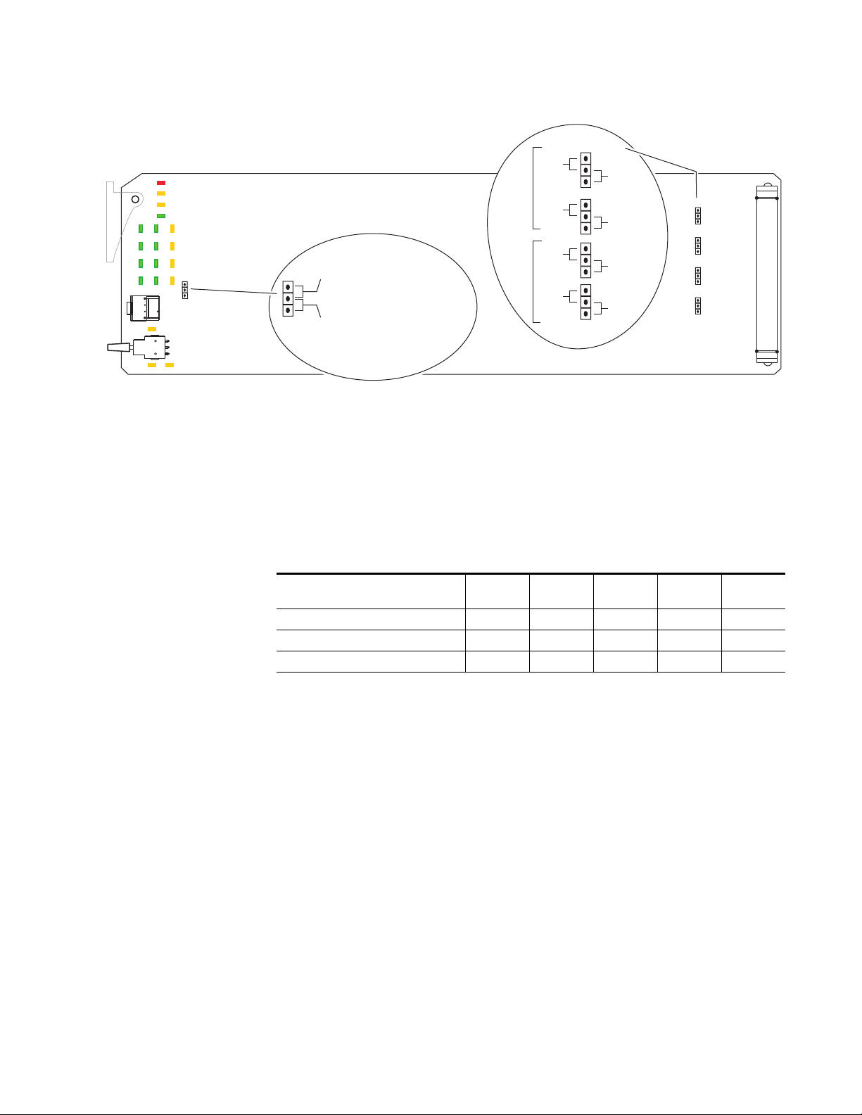
Jumpers on the 8920MUX module must be set for remote or local control
and for the audio input type with the following on-board jumpers shown
in Figure 1 on page 9:
• Jumper JP10 sets control mode for Local only or Remote and Local.
When a jumper is placed across pins 2 and 3 of jumper block JP10,
module output mode settings are adjustable from the Local on-board
switches only. To have both Local and Remote access, set the jumper
across pins 1 and 2.
• Jumpers JP1, JP5, JP7, and JP8 select either 75
balanced AES/EBU inputs. All four jumpers must be set for the correct
input type.
Ω unbalanced) and remote control lockout,
Power Up
on page 12).
Ω unbalanced or 110 Ω
Ω
8 8920MUX Instruction Manual
Page 9
Installation
Figure 1. On-board Jumper Settings
Remote Control Lockout
JP10
JP10
Frame Capacity
The 8920MUX module can be installed in all 8900 Series frames but with
varying maximum quantities determined by frame cooling capacity.
Table 1 provides the power capacity, cooling capacity, and maximum
module count for each frame type.
LOCAL –
REMOTE –
Audio Input
jumper across these pins
locks out remote control
jumper across these pins
enables remote and
local control
Selection
AES 1
AES 2
75 Ω
unbal.
75 Ω
unbal.
75 Ω
unbal.
75 Ω
unbal.
JP8
JP1
JP5
JP7
110 Ω
bal.
110 Ω
bal.
110 Ω
bal.
110 Ω
bal.
8037_11
JP1
JP5
JP7
JP8
Table 1. Power, Cooling, and Module Capacity of 8900 Frames
Capacity Calculated
Power (W) 60 60 100 100 100
Recommended Module Cooling (W) 30 60 30 90 90
8920MUX Modules 6 10 6 10 10
Note
Module capacity figures assume no other modules are in the frame.
8900T2
Frame
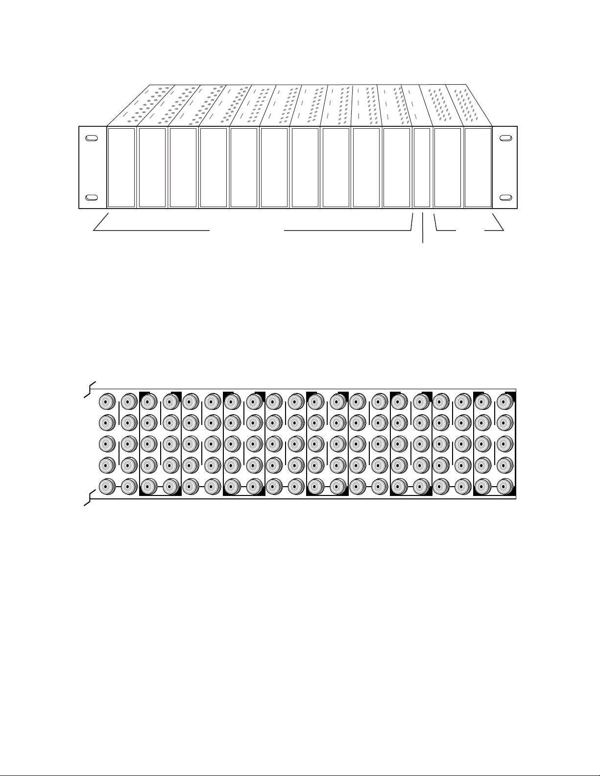
Module Placement in the 8900 Frame
There are ten slot locations in the frame to accommodate either analog or
digital modules. These are the left ten locations. Refer to Figure 2.
The two slots on the right are allocated for the power supplies. For additional information concerning the Power Supply module, refer to the 8900
Frame manual.
The third slot from the right is allocated for the Frame Monitor, or 8900NET
Network Interface module. These modules provide health monitoring and
control options.
8900T2-F
Frame
8900TX
Frame
8900TF
Frame
8900TFN
Frame
8920MUX Instruction Manual 9
Page 10
Installation
Figure 2. 8900 Series Frame
1.
2.
3.
8037-04r1
DA10
J1 J2
O
J3 J4
U
T
J5 J6
J7 J8
J9 J10
IN
DA9
J1 J2
J2
O
J3 J4
J4
U
T
J5 J6
J6
J7 J8
J8
J9 J10
IN
Any 8900 Module
Power
Supplies
Frame Controller or
(only)
8900NET Module (only)
8900 modules are interchangeable within the module slots. There are 10
BNC connectors in each slot’s I/O group. The functional assignment of
each connector in a group is determined by the module that is placed in
that slot. The maximum number of modules an 8900 frame can accept is
ten. Figure 3 illustrates the rear connector plate for an 8900 Series frame.
Figure 3. 8900 Series Frame Rear Connector
DA8
J1 J2
O
J3 J4
U
T
J5 J6
J7 J8
J9 J10
IN
DA7
J1 J2
J2
O
J3 J4
J4
U
T
J5 J6
J6
J7 J8
J8
J9 J10
IN
DA6
J1 J2
O
J3 J4
U
T
J5 J6
J7 J8
J9 J10
IN
DA5
J1 J2
J2
O
J3 J4
J4
U
T
J5 J6
J6
J7 J8
J8
J9 J10
IN
DA4
J1 J2
O
J3 J4
U
T
J5 J6
J7 J8
J9 J10
IN
DA3
J2
J1 J2
O
J4
J3 J4
U
T
J6
J5 J6
J8
J7 J8
J9 J10
IN
DA2
J1 J2
O
J3 J4
U
T
J5 J6
J7 J8
J9 J10
IN
DA1
J1 J2
O
J3 J4
U
T
J5 J6
J7 J8
J9 J10
IN
8037-03
To install a module in the frame:
Insert the module, connector end first, with the component side of the
module facing to the right and the ejector tab to the top.
Verify that the module connector seats properly against the backplane.
Press the ejector tab in to seat the module in place.
10 8920MUX Instruction Manual
Page 11
Cabling
Installation
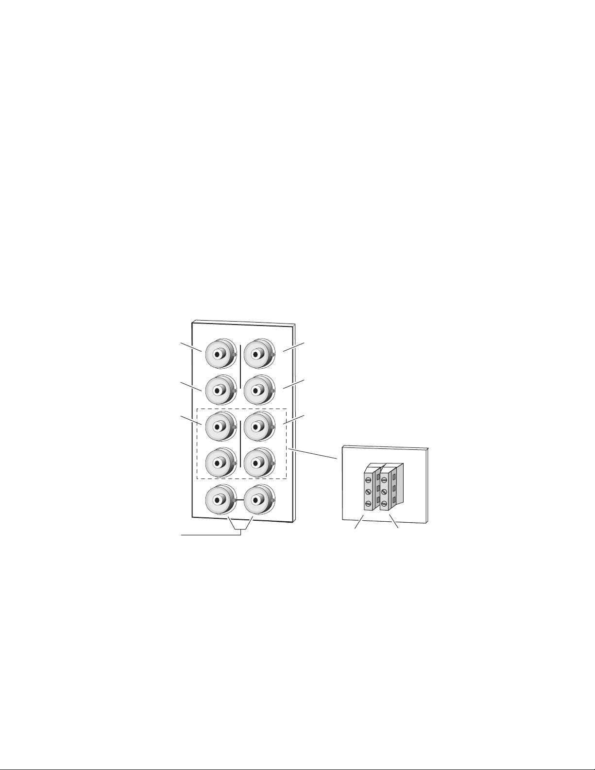
Inputs
SD Output 1
SD Output 3
AES Input 1
unbalanced 75 Ω
Note
At the back of every hard cover manual are overlay cards that can be placed
over the rear connector BNCs to identify the specific 8920MUX connector
functions.
The SD video stream is connected to the looping input BNC at J9 or J10.
For balanced audio inputs, use the terminal post adapter shown in Figure 4
to connect up to two AES/EBU input sources. The adapter connects to the
plus and minus BNC pairs J5/J7 and J6/J8.
Connect unbalanced AES/EBU input BNCs to J5 and J6.
Note
Figure 4.
J3
J5
J7
Jumper selections on the module must be made to select either 75 Ω unbalanced or 110 Ω balanced AES/EBU input (see Figure 1 on page 9).
8920MUX
X
O
U
T
J9 J10
IN
Input/Output Connectors
SD Output 2
J2J1
SD Output 4
J4
J6
J8
AES Input 2
unbalanced 75 Ω
L+
J1
GND
L–
Grass Valley
Adapt
e
r
Adapter for
R+
balanced 110 Ω
GND
inputs, connects
to BNCs J5 - J8.
R–
Loop-through
SD Input
AES
Input 1
J4
AES
Input 2
8037-02r1
Outputs
The 8920MUX provides four SD output streams—J1 through J4. The destination equipment should have a 75 Ω input impedance or loop-through
inputs that are terminated into 75
8920MUX Instruction Manual 11
Ω .
Page 12
Power Up
Power Up
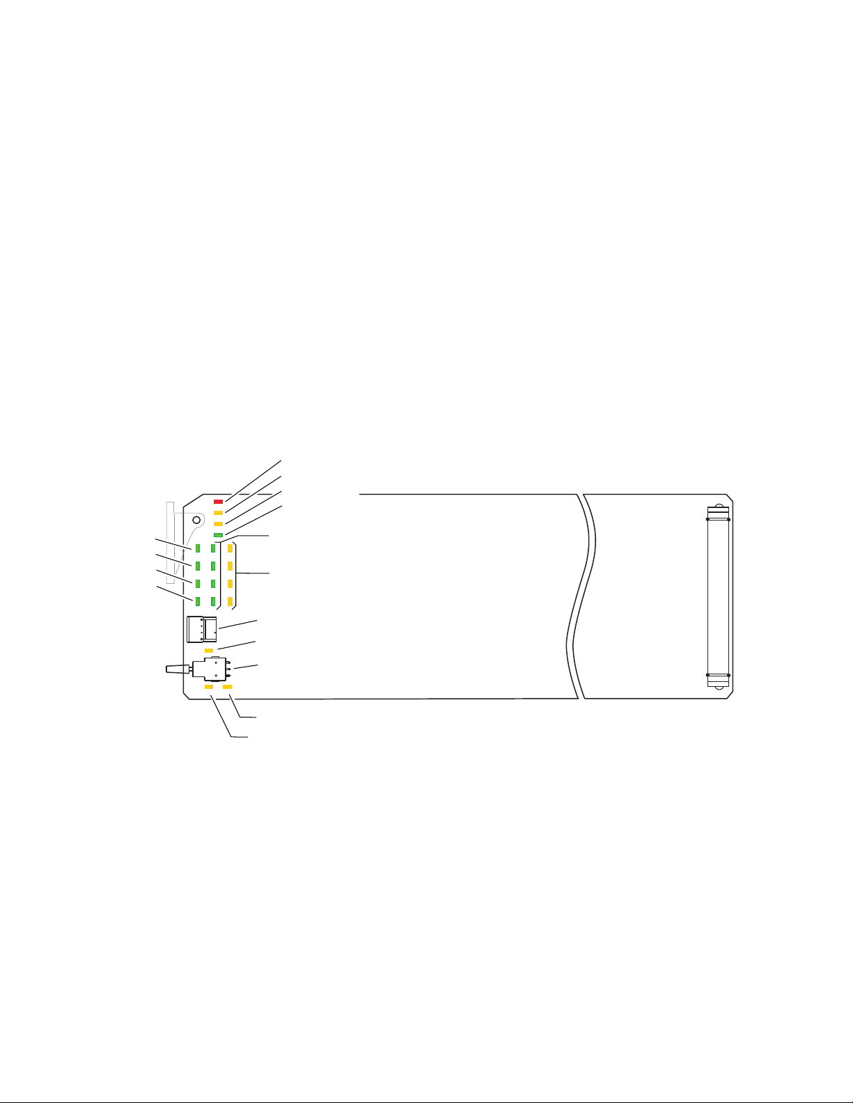
Operation Indicator LEDs
The front LED indicators and configuration switches are illustrated in
Figure 5. Upon power-up, the green PWR LED should light and the yellow
CONF LED should illuminate for the duration of module initialization.
With factory default configuration and a valid SD input with AES/EBU
audio content, the green PWR LED, the SD format (either 525 or 625) LED,
and the appropriate audio Signal Present LEDs should be on. The appropriate yellow Insert LED (G1 through G4) will indicate which audio group
(if any) the module is configured to insert.
625 (green)
525 (green)
AES 1 (green)
AES 2 (green)
Note
Figure 5. Operation Indicator LEDs
G1
G4
SW1 – Function Rotary Switch
2nd LED (yellow)
SW2 – Select/Adjust Paddle Switch
EDH presence (yellow)
24-bit Audio insertion (yellow)
A flashing Insert LED indicates an invalid insertion configuration has been
attempted and the existing audio group has not been deleted or replaced.
FAULT (red)
COMM (yellow)
CONF (yellow)
PWR (green)
Audio G1 through G4
Signal Present (green)
Audio G1 through G4
Insert (yellow)
8037_05
12 8920MUX Instruction Manual
Page 13

Power Up
A red FAULT LED indicates an error situation and, with the other LEDs,
can indicate the operational conditions presented in Table 2. The table
describes signal output and LED indications for various input/reference
combinations and user settings.
Table 2. Indicator LEDs and Conditions Indicated
LED Indication Condition
Off Normal operation.
FAULT
(red)
COMM
(yellow)
CONF
(yellow)
PWR
(green)
625
(green)
525
(green)
AES1 P
(green)
AES2 P
(green)
G1_PR
(green)
G2_PR
(green)
G3_PR
(green)
G4_PR
(green)
G1_INS
(yellow)
On continuously Module has detected an internal fault.
Long flash Configuration problems. Check inputs and settings.
Short flash EDH error detected.
Off No activity on frame communication bus.
Long flash Location Command received by the module from a remote control system.
Short flash Activity present on the frame communication bus.
Off Module is in normal operating mode.
On continuously Module is initializing, changing operating modes or updating firmware.
Off No power to module or module’s DC/DC converter failed.
On continuously Normal operation, module is powered.
Off No video or standard is other than 625.
On continuously Valid 625 video signal is present.
Off No video or standard is other than 525.
On continuously Valid 525 video signal is present.
Off No valid AES stream is present at input 1.
On continuously Valid 48 kHz AES 3 stream at input 1.
Off No valid AES stream is present at input 2.
On continuously Valid 48 kHz AES 3 stream at input 2.
Off No audio present in group G1.
On continuously Audio present in group G1 and passing through.
Flashing Audio present in group G1 but has been replaced or deleted.
Off No audio present in group G2.
On continuously Audio present in group G2 and passing through.
Flashing Audio present in group G2 but has been replaced or deleted.
Off No audio present in group G3.
On continuously Audio present in group G3 and passing through.
Flashing Audio present in group G3 but has been replaced or deleted.
Off No audio present in group G4.
On continuously Audio present in group G4 and passing through.
Flashing Audio present in group G4 but has been replaced or deleted.
Off G1 audio will not be inserted.
On continuously G1 audio will be inserted.
Flashing
G1 audio cannot be inserted because the existing G1 audio has not been
deleted or replaced.
8920MUX Instruction Manual 13
Page 14

Power Up
Table 2. Indicator LEDs and Conditions Indicated - (continued)
LED Indication Condition
Off G2 audio will not be inserted.
G2_INS
(yellow)
G3_INS
(yellow)
G4_INS
(yellow)
2ND
(green)
24b
(yellow)
EDH
(yellow)
On continuously G2 audio will be inserted.
Flashing
Off G3 audio will not be inserted.
On continuously G3 audio will be inserted.
Flashing
Off G4 audio will not be inserted.
On continuously G4 audio will be inserted.
Flashing
Off
On continuously Second bank of functions is being addressed.
Off Encoding is 20-bit.
On continuously Encoding is 24-bit.
Off Normal operation, EDH packet present in incoming SD stream.
On
G2 audio cannot be inserted because the existing G2 audio has not been
deleted or replaced.
G3 audio cannot be inserted because the existing G3 audio has not been
deleted or replaced.
G4 audio cannot be inserted because the existing G4 audio has not been
deleted or replaced.
First bank of configuration functions is being addressed by the Function
Rotary Switch (SW1).
EDH packet not present in incoming SD stream. The module will report a signal or PLL (phase lock) loss condition.
Table 3 provides the possible input conditions and the output condition
that results and front LED status.
Table 3. Possible Operating Conditions
SD Video Input AES/EBU Input Setting Mode(s) Output Condition
Video input present Synchronous 48 kHz
audio input present
Video input present Synchronous 48 kHz
audio input present
Video input present Synchronous 48 kHz
audio input present
Video input present Synchronous 48 kHz
audio input present
Video input present Synchronous 48 kHz
audio input present
Pass all syn.AES
Auto insert syn.AES
Insert G1, G2,
G3, or G4
Replace G1,
G2, G3, or G4
Delete all syn.AES
asyn.AES
syn.matrix
asyn.AES
syn.matrix
syn.AES
asyn.AES
syn.matrix
syn.AES
asyn.AES
asyn.AES
Input signal will be passed to the output with no new group embedded.
Since no new group insertion is selected, AES1 P and AES2 P LEDs
(signal present) will be on if any AES stream is present. G1-4_PR (signal present) LEDs will be on to indicate any embedded audio groups
present.
8920MUX will insert the input AES/EBU audio into the first
available audio group (G1 through G4) and light the corresponding
G1-4_INS (insert) LEDs. If all groups are occupied, no new group will
be added and the G1-4_INS LEDs will flash.
8920MUX will insert a new audio group with the appropriate group ID
and light the corresponding G1-4_INS LED. If the group already exists,
no new group will be inserted and the corresponding G1-4_INS LED
will flash.
8920MUX will insert a new audio group with the appropriate group ID
and light the corresponding G1-4_INS LED. If the group already exists
it will be replaced with the new group and the corresponding G1-4_PR
LED will flash.
All existing incoming audio groups will be deleted and the G1-4_PR
LEDs will flash. If an insert setting is selected, the module will insert
one group and light the corresponding G1-4_INS LED.
14 8920MUX Instruction Manual
Page 15

Table 3. Possible Operating Conditions
SD Video Input AES/EBU Input Setting Mode(s) Output Condition
Video input present Synchronous 48 kHz
audio input present
Video input present Synchronous 48 kHz
audio input present
Video input present Synchronous 48 kHz
audio input present
Video input present No audio input Any syn.AES
No video input Any state Any syn.AES
Video input present Asynchronous
48 kHz audio input
present
Video input present Asynchronous
48 kHz audio input
present
Video Input present Both audio inputs are
not 48 kHz
Video input present One audio input is
not 48 kHz and the
other is 48 kHz
Delete G1, G2,
G3, or G4
20-bit syn.AES
24-bit syn.AES
Any syn.AES
Any asyn.AES AES1 P and AES2 P LEDs will be on. The module will embed the new
Any syn.AES
Any syn.AES
syn.AES
asyn.AES
asyn.AES
syn.matrix
asyn.AES
syn.matrix
asyn.AES
syn.matrix
asyn.AES
syn.matrix
syn.matrix
asyn.AES
syn.matrix
asyn.AES
syn.matrix
The selected group, if present, will be deleted from the incoming stream
and the corresponding G1-4_PR will flash. If insert is selected for the
corresponding group, the module will insert the AES/EBU input as that
group and light the G1-4_INS LED.
The newly inserted group will be inserted in the 20-bit format. The 24b
LED will be off.
The newly inserted group will be inserted in the 24-bit format using the
extended audio packet for the additional bits. The 24b LED will be on.
Input signal will be passed to the output with no new group embedded.
AES1 P and AES2 P LEDs will be off.
Output is random noise (low level static). The 525 and 625 LEDs indicating valid input video will be off.
AES1 P and AES2 P LEDs will be on if the AES audio is close to the
correct frequency. If an insert or replace is selected, the module will try
to embed the new group but a click or noise will be noticeable. If the
frequency is not close, the group will not be embedded and the AES1 P
and AES2 P LEDs will be off.
group and light the corresponding G1-4_INS LED. If the frequency is
not close, the group will not be embedded and the AES1 P and AES2 P
will be off. Small audio effects will be heard at slow rate due to dropping or repeating samples in asyn.AES mode.
No audio groups will be added and AES1 P and AES2 P LEDs will be
off and G1-4_INS LED will flash.
Audio group will be added and AES1 P and AES2 P LEDs will be off for
non-48 kHz audio and on for 48 kHz input and G1-4_INS LED will be
on. The channels related to the non-48 kHz audio will be missing in the
embedded group.
Power Up
8920MUX Instruction Manual 15
Page 16

Configuration
Configuration
The 8920MUX can be configured locally using on-board switches or
remotely using the 8900NET network interface GUI or a networked
Newton Control Panel. Operation of these control types is explained in
detail in their respective sections of this manual.
Refer to the following sections for configuration instructions:
•Configuration Summary (page 16)
• Local On-board Module Configuration (page 21)
•Remote Control and Monitoring (page 23)
•Newton Control Panel Configuration (page 34)
Configuration Summary
A configuration summary is provided in this section for the following
items on the 8920MUX:
•Multiplexing (audio insertion/deletion) to determine output composition (page 17),
• Synchronization modes (page 18), and
•AES Input Channel Status Bits (page 19).
Table 5 on page 20 provides a summary in table format of all parameters
and their ranges, default values, and remote, local, and control panel function names and locations for setting each value.
16 8920MUX Instruction Manual
Page 17

Video
Multiplexing
Figure 6 illustrates the various multiplexing functions available in the
8920MUX. The module can be used to delete or pass either:
•All of the ancillary data in the SD input stream, or
•One of the four audio groups (G1, G2, G3, or G4).
Figure 6. 8920MUX Multiplexing Options
SD Input
Ancillary Data
8920MUX
Delete/Pass
Functions
• Delete or pass all ancillary
data
• Delete or pass all groups,
delete 1 of 4 audio groups
G1, G2, G3, or G4
Configuration
Insert/Replace
Functions
• Off
• Insert audio as G1
• Insert audio as G2
• Insert audio as G3
• Insert audio as G4
• Auto insert in first available
audio group space
• Replace G1 audio group
• Replace G2 audio group
• Replace G3 audio group
• Replace G4 audio group
Audio Input
Multiplex:
One audio group
AES 1 (2 channels) AES 2 (2 channels)
8037_07r1
The Insert function allows you to insert the AES/EBU input into any one of
the audio groups (G1 through G4). If the selected group is already occupied
in the stream, the appropriate yellow Insert LED at the front of the module
will flash to indicate an invalid operation and the insertion is not performed.
The Replace function removes any data in the designated group and inserts
the module’s AES/EBU input signal in that group.
Note
Note
Ancillary data space can be limited when using 24-bit audio. Refer to Using
Ancillary Space in the SMPTE standard.
The 8920MUX inserts or replaces only one audio group. To change more than
one audio group in the SD stream, you can cable multiple modules in series
and configure each module to manipulate one of the four groups (see
Figure 7 on page 18).
Note
The EDH Feed Forward bits from the incoming video for the Full Field and
Active Picture are ignored and set to No Error by the multiplexer IC.
8920MUX Instruction Manual 17
Page 18

Configuration
SD Input
Figure 7. Multiple 8920MUXs in Series
In Out In Out In Out In Out
MUX 1 MUX 2 MUX 3 MUX 4
Audio
group
1 insert
Audio
group
2 insert
Audio
group
3 insert
Synchronization Modes
The 8920MUX can be configured to run in one of three sync modes:
• Synchronous – for AES input (48 kHz, 20/24 bits) that is synchronized
to SD video,
•Asynchronous – for asynchronous AES input (48 kHz, 20/24 bits, grade
2 compliant AES audio within ± 50 ppm of the 48 kHz sample rate), or
Audio
group
4 insert
Four
groups
inserted
SD Output
8037_08
• Sync Matrix – synchronous mode with control of audio channel
switching.
Note In Sync Matrix mode, Delete and Replace functions are not available. The
incoming signal must already have space available in the ancillary data for the
AES audio group insertion.
Any one of the three modes can be selected either using on-board switches
or the remote control interfaces (when remote control is enabled). The
switching of audio channel content is done using the GUI or control panel
only (see Audio Matrix on page 29).
Note In Asynchronous mode, the 8920MUX may add or drop audio samples in
each audio channel to maintain correct timing with the SD video signal. This
process can produce timing errors of up to ± 2 audio samples between channels in the AES stream. Applications requiring exact audio timing should use
one of the synchronous modes.
18 8920MUX Instruction Manual
Page 19

Configuration
AES Input Channel Status Bits
AES input channel status bits are handled differently in each of the three
sync modes. The synchronous AES mode (syn.AES) passes the channel
status bits from the AES inputs. The asynchronous AES (asyn.AES) and
synchronous Matrix mode (syn.matrix) modify the input status bits to
prevent random bits from occurring. Refer to Table 4 for a detailed over-
view of what the channel status bits are set to for each mode.
Table 4. AES Channel Status Bits For Each Mode
Byte Bit Description Sync Mode Sync Matrix Mode Async Mode
0 Professional/Consumer Pass Professional=1 Professional=1
1 Audio/Non-audio Pass Audio=0 Audio=0
2
Byte 0
Byte 1
Byte 2
Bytes 3-22 Various Pass All zeros All zeros
Byte 23 0-7 CRC
3
4
5 Fs locked/unlocked Pass Locked=0 Locked=0
6
7
0
1
2
3
4
5
6
7
0
1
2
3
5
6
7
VValidity Bit Pass Pass Pass
U User Data Bit Pass Pass Pass
C Channel Status Bit See above See above See above
P Parity Bit Pass Set by firmware Set by firmware
Emphasis Pass
Sampling Rate Pass
Channel Mode Pass
User Bit Mode Pass
Aux Sample Bits
Audio Sample Length
Reserved=00 Pass 00 00
Pass (may be wrong if the
Mux setting of 20/24 bits
does not match input)
Pass (may be wrong if the
Mux setting does not
match input)
CRC made correct by Mux
IC if incorrect
No emphasis
100
48 kHz
01
Not indicated
0000
No user information
indicated 0000
Follows web page:
20 bit=000
24 bit=001
Not indicated=000 Not indicated=0004
20 bit=71h
24 bit=1Eh
No emphasis
100
48 kHz
01
Not indicated
0000
No user information
indicated 0000
Follows web page:
20 bit=000
24 bit=001
20 bit=71h
24 bit=1Eh
8920MUX Instruction Manual 19
Page 20

Configuration
Table 5 provides a complete summary of the 8920MUX functions and a
comparison of the functionality available with each control type along with
the ranges and default values for each parameter.
Table 5. Summary of 8920MUX Configuration Functions
Function
Type Default
Pass/Delete Audio Groups Pass All
Insert/Replace Group Auto Insert
Bits per sample 20 bit 20 or 24 bit
Synchronization mode syn.AES
Input to AES1A Out AES1A
Input to AES1B Out AES1B
Input to AES2A Out AES2A
Input to AES2B Out AES2B
Recall user settings
Save user settings 2:F (down 3 sec.)
Recall factory defaults See above
N/A N/A
Range/Choices
Resolution
Pass All
Delete All 2:1
Delete G1 2:2
Delete G2 2:3
Delete G3 2:4
Delete G4 2:5
Auto Insert
Insert G1 1:4
Insert G2 1:5
Insert G3 1:6
Insert G4 1:7
Replace G1 1:8
Replace G2 1:9
Replace G3 1:A
Replace G4 1:B
Off 1:3 (paddle down)
syn.AES,
asyn.AES, or
syn.matrix
AES1A, AES1B,
AES2A, AES2B
Web Page/
Function Name
Audio Group Management/
Pass/Delete Group
pulldown
Audio Group Management/
Insert/Replace Group
pulldown
Audio Group Management/
Bits per Sample pulldown
Audio Group Management/
Synchronization pulldown
Audio Matrix/
AES1A Out, AES1B Out,
AES2A Out, AES2B Out
pulldowns
Recall/Save User Settings/
Recalls User Setup or
Save User Setup button
Recall Fact Default
button
Jumper or
Rotary Switch
Bank/Setting
1:2
1:3 (paddle up)
1:C
(20 bits up)
(24 bits down)
1:D up (syn.matrix)
1:E up (syn.AES)
1:E down (asyn.AES)
N/A N/A
2:F (up)
1:F N/A
Newton
Panel
Mnemonic
Pass/Del
Ins/Repl
Bits/Smpl
Synchron
N/A
Notes/
Conditions
In local mode,
move paddle up
to delete and
down to pass all.
In local mode,
move paddle up
to insert or
replace. Moving
paddle down has
no function.
See Synchroniza-
tion Modes on
page 18.
Remote control
setting only.
Active in
syn.matrix mode.
20 8920MUX Instruction Manual
Page 21

Local On-board Configuration
The module parameters can be configured locally using the on-board
rotary switch, the paddle switch and LEDs as described in Table 6 on
page 22. The CONF LED indicates status of the configuration process.
Use the following controls illustrated in Figure 8 to configure the module
locally:
• Function (rotary) switch selects a desired configuration parameter from
two banks of 16 positions each (0 through 9, A through F), although not
all positions are used.
•SW1 paddle switch initiates a configuration parameter selection.
• CONF (configuring) LED when on, indicates the module is initializing
or processing configuration information.
Figure 8. Module Configuration Switches and LEDs
CONF (yellow)
Configuration
SW1 – Function Rotary Switch
2nd – LED on for 2nd Bank Selections
SW2 – Selection Paddle Switch
8037_06r1
8920MUX Instruction Manual 21
Page 22

Configuration
The 8920MUX provides 18 configuration functions across two banks of the
rotary switch positions (shown in Table 6). To make a configuration setting,
rotate the switch to the desired configuration parameter. The 16-position
rotary switch increments through 32 selection positions by addressing a
first and second bank of 16. When the switch is in the second bank, the 2nd
LED is illuminated. Move the paddle switch momentarily to either the up
or down position to make the desired selection
Refer also to Table 5 on page 20 for an over view of each of the parameters
and their default values.
Table 6. 8920MUX Configuration Functions
Function
Switch
0----Inactive position.
1----Not used.
2 Pass all -- Passes all audio channels to the outputs.
3 Auto-insert on Auto-insert off Automatic insertion of input AES/EBU audio into first available group.
4 Insert G1
5 Insert G2 -- Inserts the input audio group as G2 in the SD stream.
6 Insert G3 -- Inserts the input audio group as G3 in the SD stream.
7 Insert G4 -- Inserts the input audio group as G4 in the SD stream.
8 Replace G1
9 Replace G2 -- Replaces the existing G2 audio group in the SD stream with the audio input to this module.
Bank 1
A Replace G3 -- Replaces the existing G3 audio group in the SD stream with the audio input to this module.
B Replace G4 -- Replaces the existing G4 audio group in the SD stream with the audio input to this module.
C 20-bit 24-bit Select AES/EBU audio format.
D Sync Matrix --
E Sync AES Async AES
F Recall factory defaults -- Recalls the initial factory setups. as given in Table 5 on page 20.
0----Inactive position.
1 Delete all
2 Delete G1
3 Delete G2 Removes G2 AES/EBU from the SD stream.
4 Delete G3 Removes G3 AES/EBU from the SD stream.
5 Delete G4 Removes G4 AES/EBU from the SD stream.
Bank 2
6 thru 9 -- -- Not used.
A thru E -- -- Not used.
F Recall
1
To Save current settings, the toggle switch must be held down for at least 3 seconds.
Paddle
Switch Up
Only
one
group
can be
inserted
Only
one
group
can be
replaced
Only
one
group
can be
deleted
Paddle
Switch
Down
-- Inserts the input audio group as G1 in the SD stream.
-- Replaces the existing G1 audio group in the SD stream with the audio input to this module.
Set to Sync Matrix when AES audio is in sync with SD video stream and status/control bits
are required. This configuration also allows switching of channel content in the audio group
using the GUI remote control interface.
Set to Sync AES when AES audio is in sync with SD video stream and status/control bits are
required or set to Async AES when inputs not in sync and status/control bits are not
required.
Removes all ancillary data from the SD stream.
Removes G1 AES/EBU group from the SD stream.
Pass All
Save
(Down x 3
Recall previously saved user default configuration, or Save current configuration settings as
1
the user default.
)
Function Description
22 8920MUX Instruction Manual
Page 23

Remote Configuration and Monitoring
8920MUX configuration and monitoring can be performed using a web
browser GUI interface or a Newton Control Panel when the 8900NET
Network Interface module is present in the audio frame (Gecko 8900TFN-V
frame).
Note 8900NET module software must be version 3.2.0 or later.
This section describes the GUI access to the module configuration functions. Refer to the Frame Status page shown in Figure 9.
Figure 9. 8900NET GUI
The Links section lists the frame and its current modules. The selected link's Status
page is first displayed and the sub-list of links for the selection is opened. The sub-list
allows you to select a particular information page for the selected device.
Content display section displays the information page
for the selected frame or module (frame slot icons are also
active links).
Refresh button for manual
update of page
Configuration
Online Manual Link
8037_10
For Newton Control Panel control, refer to Newton Control Panel Configura-
tion on page 34.
For remote access, make sure the jumper block on the module is set for both
Local and Remote access (Figure 8 on page 21). Audio inputs must also be
specified as balanced or unbalanced with jumpers J1, J5, J7, and J8 as
described in Setting On-Board Jumpers on page 8.
8920MUX Instruction Manual 23
Page 24

Configuration
Refer to the 8900NET Network Interface Module Instruction Manual for information on the 8900NET Network Interface module and setting up and
operating the Gecko 8900 frame network.
The 8900 modules can be addressed by clicking either on a specific module
icon in the frame status display or on a module name or slot number in the
link list on the left.
Note The physical appearance of the menu displays on the web pages shown in
this manual represent the use of a particular platform, browser and version
of 8900NET module software. They are provided for reference only. Displays
will differ depending on the type of platform and browser you are using and
the version of the 8900NET software installed in your system.
Use the Refresh button to update the display (available with 8900NET software version 3.0 and later).
The
Online Manual Link button can be set up to link to the documentation in
pdf format. Link configuration is done on the Frame Configuration page.
For information on status and fault monitoring and reporting shown on the
Status page, refer to Status Monitoring on page 38.
The 8920MUX will indicate a SMPTE Alarm fault on the Frame Status
display for the following alarms:
• Lack of valid video input, or
• Board failure.
24 8920MUX Instruction Manual
Page 25

8920MUX Links and Web Pages
The 8900 GUI provides the following links and web pages for the 8920MUX
module (Figure 10):
• Status – reports input and reference signal status and module information (page 26),
•Audio Group Management – provides controls for setting audio group
functions (page 27),
•Audio Matrix – shows the input/output audio matrix assignments
(page 29),
•Recall/Save User Settings– provides recall and save functions for local
operations as well as recalling factory defaults (page 30),
• Slot Config – provides a Locate Module function and Slot Memory
(page 31), and
• Software Update – gives information on software updating (page 33).
Figure 10. 8920MUX Web Page Links
Configuration
Refer also to Table 5 on page 20 for an over view of each of the parameters
and their default values.
8920MUX Instruction Manual 25
Page 26

Configuration
Use
this
link
Status Page
The Status page (Figure 11) shows the signal status of the audio input and
frame bus communication. Color coding of the display indicates the signal
status. Refer to Status Monitoring on page 38 for an explanation of the color
coding.
Information about the module, such as part number, serial number, hardware revision and software and firmware versions are given in a read-only
section at the bottom of the display.
Figure 11. 8920MUX Status Page
26 8920MUX Instruction Manual
Page 27

Use
this
link
Configuration
Audio Group Management
The Audio Group Management page (see Figure 12 on page 28) allows you
to perform the following functions:
•
Pass/Delete Group all audio groups or delete one audio group,
• Insert or replace audio content in one available audio group,
•Turn off the
• Set audio sample rate (
• Set AES audio-to-video input synchronization mode:
• Synchronous – AES audio is in sync with SD video and will pass
status/control bits
•Asynchronous – AES audio is not in sync with input video and
status/control bits will not be passed, or
• Synchronous with matrix control – AES audio channel content is
controlled through a switching matrix on the Audio Matrix page
(see Audio Matrix on page 29).
Note Replace and Delete functions are not available in Synchronous Matrix mode.
AES audio is inserted in available space only.
Click the Apply button to activate each selection.
Auto Insert places the AES/EBU input in the first available audio group. If
no group is empty, the Status line will report a warning for all groups.
The status reporting section of the display provides monitoring of:
Insert/Replace Group function,
Bits per Sample), and
•Audio groups present in the SD input,
• Status of the group insert/replace function, and
•Audio groups present in the SD output.
CAUTION When monitoring the status of the signal configuration, be aware that this
page is a static display and requires manual refresh. Changing SD input
upstream can cause changes to the 8920MUX output that will not be reported
until status refresh is activated. To refresh the status information, click on the
Audio Group Management link, the Refresh button, or an Apply button.
8920MUX Instruction Manual 27
Page 28

Configuration
Figure 12. Audio Group Management Display
28 8920MUX Instruction Manual
Page 29

Use
this
link
Configuration
Audio Matrix
When Synchronization is set to Synchronous with matrix control mode
(syn.matrix) as described in Audio Group Management on page 27, the Audio
Matrix page (see Figure 13) allows you to switch any one of the four input
audio channels from the selected audio group (G1, G2, G3, or G4) into any
or all of the output audio channels.
Pull-down menus allow you to select any of the four input channels
(AES1A, AES1B, AES2A, or AES2B) for insertion in each of the output channels.The Input/Output map indicates the selected input channel by
placing an
When Synchronization is set to Synchronous (syn.AES) or Asynchronous
(asyn.AES) modes, the display will show only the default channel assigments.
Figure 13. Audio Matrix Display
X in the appropriate input row for each output column.
8920MUX Instruction Manual 29
Page 30

Configuration
Recall/Save User Settings
The Recall/Save User Settings page (see Figure 14) allows you to set the
following parameters:
•Recall the saved User Setup,
Use
this
link
• Save the currently selected settings for the entire module as User Setup,
or
•Recall factory defaults.
Figure 14. User Settings Display
30 8920MUX Instruction Manual
Page 31

Use
this
link
Configuration
Slot Config Page
Use the Slot Config page (Figure 15 on page 32) to perform the following
functions on the 8920MUX module:
•
Locate Module – selecting the Flash radio button flashes the yellow
COMM and CONF LEDs on the front of the module so it can be located
in the frame.
•
Slot Identification – You may identify the module by typing a specific
name in the
module and travels with the 8900NET module if it is moved to another
frame. Select
•
Slot Memory – the slot configuration for each media module is automati-
cally saved periodically (once an hour) to the 8900NET module in that
frame. You may also select the
save the current configuration for this slot. The configuration is saved
on the 8900NET module. If the 8900NET module is removed or
powered down, the stored configurations are not saved.
Name field. The assigned name is stored on the 8900NET
Default to enter the factory default module name.
Learn Module Config button at any time to
When the
ration saved to this slot is saved as slot memory. When the current
module is removed and another module of the same type is installed,
the configuration saved to the 8900NET module will be downloaded to
the new module. The box must be checked before the current module
with the saved configuration is removed.
•
Hardware Switch Controls – a read-only status report of 8900NET module
switch settings for Module Status Reporting and Asynchronous Status
Reporting. These functions must be enabled for the following Slot
SNMP Trap Reports to function.
•
Slot SNMP Trap Reports – displayed only when the SNMP Agent software
has been installed on the 8900NET module. Slot SNMP traps can be
enabled only when the hardware switches for Module Fault reporting
and Asynchronous Status reporting are in enabled on the 8900NET
module (dipswitch S1 segment 7 and dipswitch S2 segment 1).
The enabled SNMP traps will be reported to any SNMP manager that
is identified as an SNMP Report Destination in 8900NET configuration.
Trap severity is read-only hard-coded information that is interpreted
and responded to by the SNMP Manager software configuration.
Restore upon Install box has been checked, the current configu-
8920MUX Instruction Manual 31
Page 32

Configuration
Figure 15. 8920MUX Slot Config Page
32 8920MUX Instruction Manual
Page 33

Use
this
link
Configuration
Software Update Page
The Software Update page (Figure 16) indicates that module software
updates via the web or using the NetConfig networking application are not
supported. For instructions on updating to the latest software, refer first to
the 8920MUX Release Notes that accompany the software update for complete details.
Currently, the only recommended method of software updating is done
with a software kit (8900-FLOAD-CBL) that includes a CD-ROM with the
current software files and a serial cable assembly available from Grass
Valley.
Refer to the 8900-FLOAD-CBL Software Upgrade Instruction Manual in pdf
format on the CD-ROM for complete updating instructions and the
required software files for the 8920MUX.
Figure 16. 8920MUX Software Update Page
8920MUX Instruction Manual 33
Page 34

Configuration
Newton Control Panel Configuration
A Newton Control Panel can be interfaced to the Gecko 8900 Series frame
over the local network to control 8920MUX configuration and control
parameters.
Note The 8900NET module in the Gecko 8900 frame must be running software
version 3.2.0 or later for proper operation of the Newton Control Panel.
The available control panel controls are listed in Table 5 on page 20. An
example of the Newton Configurator for the 8920MUX is shown in
Figure 17.
Note Not all control parameters are available with the control panel.
Figure 17. Newton Configurator Example
Refer to the documentation that accompanies the Newton Control Panel for
installation, configuration, and operation information.
34 8920MUX Instruction Manual
Page 35

Specifications
Specifications
Table 7. 8920MUX Specifications
Parameter Value
SDI Input
Number of inputs 1 loop-through
Connector type BNC
Input impedance High impedance
Signal type 270 Mbit signal format, SMPTE 259M serial 10-bit 4:2:2 component
video, 525 or 625
Signal level SDI
Return loss >15 dB, 5 to 270 MHz
Cable equalization Automatic for <984 ft (300 m)
Digital Audio Input
Number of inputs 2
Signal type AES/EBU
Connector type Unbalanced – One 75Ω BNC per input
Balanced – One 110 Ω terminal block per input (with adapter)
Input impedance 75 Ω or 110 Ω
Sampling rate 48 kHz sample rate 20 or 24-bit
Signal level 1 V peak to peak
SDI Output
Number of outputs 4
Connector type BNC
Signal type SMPTE 259M
Return loss >15 dB, 5 to 270 MHz
Output impedance 75 Ω
Error checking EDH embedded
Clock jitter <0.2 UI
Signal Processing Functions
Electrical length 12 µs
Audio delay 875 µs
Audio format 48 kHz synchronous audio formatted per proposed SMPTE standard
“Formatting AES/EBU audio and auxiliary data into digital video ancil-
lary data space.”
Interchannel crosstalk <-100 dB, 20 Hz - 20 kHz
Signal
Mode 1 AES/EBU 48 kHz sample rate, 20/24 bits, must be synchronous with
SD video
Mode 2 AES/EBU 48 kHz sample rate, 20/24 bits, frequency minimum grade 2
compliant
Mode 3 AES/EBU 48 kHz sample rate, 20/24 bits, must be synchronous with
SD video
Signal Level 1 V peak-to-peak nominal
8920MUX Instruction Manual 35
Page 36

Specifications
Table 7. 8920MUX Specifications - (continued)
Parameter Value
Environmental
Frame temperature range 0 to 40 degrees C
Operating humidity range 0 to 90% non-condensing
Non-operating temperature -10 to 70 degrees C
Mechanical
Frame type 8900 Series
Power Requirements
Supply voltage +12 V/-12 V
Power consumption 4.5 Watts
36 8920MUX Instruction Manual
Page 37

Service
Service
The 8920MUX modules make extensive use of surface-mount technology
and programmed parts to achieve compact size and adherence to
demanding technical specifications. Circuit modules should not be serviced in the field.
If your module is not operating correctly, proceed as follows:
•Check frame and module power and signal present LEDs. If module
power has failed, check Fuse F1 (see Figure 18).
•Check for presence and quality of input signals.
•Verify that source equipment is operating correctly and the AES/EBU
input stream is 48 kHz and synchronized with the SD video input.
•Check cable connections.
•Check output connections for correct I/O mapping (correct input connector is used for the corresponding channel output).
Refer to Figure 5 for the location of PWR LED and Table 2 on page 13 for
proper LED indications.
If the module is still not operating correctly, replace it with a known good
spare and return the faulty module to a designated Grass Valley repair
depot. Call your Grass Valley representative for depot location.
Refer to the Contacting Grass Valley at the front of this document for the
Grass Valley Customer Support Information number.
Figure 18. 8920MUX Module Fuse Location
Fuse: 2 A FAST, 125 V
JP1
JP5
JP10
JP7
F1
JP8
8037_09
8920MUX Instruction Manual 37
Page 38

Status Monitoring
Status Monitoring
This section provides a summary of status monitoring and reporting for a
Gecko 8900 Series system. It also summarizes what status items are
reported and how to enable/disable reporting of each item. There are a
number of ways to monitor status of modules, power supplies, fans and
other status items depending on the method of monitoring being used.
8900 Frame status will report the following items:
• Power supply health,
• Status of fans in the frame front cover,
•Temperature,
•Module health, and
• Frame bus status.
Module health status will report the following items:
• Internal module state (and state of submodule or options enabled)
including configuration errors (warning), internal faults, and normal
operation (Pass).
LEDs
• Signal input states including valid/present (pass), not present or
invalid (warning), not monitored, and not available (no signal inputs).
•Reference input states including locked/valid (pass), not
locked/invalid (warning), and not monitored.
• Signal output states with reporting functionality (reference output).
LEDs on modules in the frame and on the front of the 8900TF/TFN frames
indicate status of the frame and the installed power supplies, fans in the
front covers, and modules. (The 8900TX-V/A frames have no LED indicators on the front cover.)
When a red FAULT LED is lit on a frame front cover, the fault will also be
reported on the 8900NET or Frame Monitor module. The LEDs on the front
of these modules can then be read to determine the following fault conditions:
• Power Supply 1 and 2 health,
• Fan rotation status,
• Frame over-temperature condition,
• Frame Bus fault (8900NET only), and
•Module health bus.
38 8920MUX Instruction Manual
Page 39

Frame Alarm
Status Monitoring
In general, LED colors used on the frame and modules indicate:
•Green – normal operation, (Pass) or signal present, module locked.
•Red – On continuously = fault condition, flashing = configuration error.
•Yellow – On continuously = active condition (configuration mode or
communication), flashing in sequence = module locator function.
Status LEDs for this module are described in Indicator LEDs and Conditions
Indicated on page 13. LEDs for the 8900NET module are described in the
8900NET Network Interface Instruction Manual.
A Frame Alarm connection is available on pins 8 and 9 of the RS-232 connector on the rear of the 8900 frame (Frame Monitor or 8900NET Network
Interface module required). This will report any of the status items enabled
with the 8900NET or Frame Monitor module configuration DIP switch.
Connection and use of the Frame Alarm is covered in detail in the 8900NET
Network Interface Instruction Manual.
Web Browser Interface
When the 8900NET module is installed in the frame, a web browser GUI
can indicate frame and module status on the following web pages:
• Frame Status page – reports overall frame and module status in graph-
ical and text formats.
•Module Status page – shows specific input and reference signal status
to the module along with enabled options and module versions.
•A Status LED icon on each web page to report communication status
for the frame slot and acts as a link to the Status page where warnings
and faults are displayed (8900NET version 3.0 or later).
In general, graphics and text colors used indicate the following:
•Green = Pass – signal or reference present, no problems detected.
•Red = Fault – fault condition.
•Yellow = Warning – signal is absent, has errors, or is mis-configured.
•Gray = Not monitored (older 8900 module).
•White = Not present.
Status reporting for the frame is enabled or disabled with the configuration
DIP switches on the 8900NET module. Most module status reporting items
can be enabled or disabled on individual configuration web pages.
8920MUX Instruction Manual 39
Page 40

Status Monitoring
SNMP Reporting
The Gecko 8900 Series system uses the Simple Network Monitoring Protocol (SNMP) internet standard for reporting status information to remote
monitoring stations. When SNMP Agent software is installed on the
8900NET module, enabled status reports are sent to an SNMP Manager
such as the Grass Valley’s NetCentral application.
There are both hardware and software report enable switches for each
report. Both must be enabled for the report to be sent. Software report
switches are set on the 8900NET Configuration page for the Frame, the
8900NET module, and each module slot. Refer to the 8900NET Network
Interface Instruction Manual for installation instructions.
40 8920MUX Instruction Manual
Page 41

Functional Description
Serial
Digital
Video
Input
Amplifier
& Equalizer
Clock
Regen.
AES Input
Stereo 1
AES Input
Stereo 2
Audio
In 1
Audio
In 2
Network Interface CPU
Functional Description
The 8920MUX inserts up to two 20- or 24-bit AES/EBU audio streams (2
channels per stream). The audio is collected into a group of up to 2 AES
streams (four channels total). The audio group can be assigned one of four
group IDs (G1, G2, G3, or G4) and can be inserted into the Ancillary Data
of the SD stream. In Auto mode the group can be inserted with the first
available group ID if one is not already present. If a group with the same
ID is present in the stream, the new group cannot be inserted unless the
replace or delete function is used.
Refer to the block diagram in Figure 19 while reading the following functional description.
Figure 19. 8920MUX Block Diagram
Serial Digital & Audio
Serial to
Parallel
Converter
27 Mhz,
64 aFS,
128 aFS
Phase
Lock
Loop
CPU Interface
FPGA
Group
Control
Logic
MUX
Rotary
Switch
DIP
Switches
Parallel
to Serial
Converter
User
Setup
Switch
Logic
Output Driver
Audio G4
Audio G3
Audio G2
Audio G1
AS2 present
AS1 present
625 Mode
525 Mode
2ND
LED
Display
Serial
Digital
Outputs
Insert G4
Insert G3
Insert G2
Insert G1
24-b
EDH
Fault
Comm
Conf
Pwr
8037-01
Input Equalizing Amplifier
The equalizing amplifier lowers the impedance of the termination as frequency increases. The differential input improves the performance of the
8920MUX in the presence of common mode hum and noise.
8920MUX Instruction Manual 41
Page 42

Functional Description
Serial to Parallel Converter and EDH/EDA Error Processor
27Mhz Phase Lock Loop (PLL)
Field Programmable Gate Array (FPGA)
This circuit converts the serial data stream to the parallel data using the
regenerated clock signal. Deserialized data passes through the EDH processor. The EDH processor checks for a possible data or bit error in the
incoming data. Any error is reported to an FPGA internal register.
From the incoming 27 MHz clock, the PLL generates an internal, locked 27
MHz signal or produces an approximate 27 MHz free running clock in the
event no input signal is detected.
The FPGA contains 3 independent blocks:
•Ancillary space manager
• 6.144 Mhz clock generator
•CPU interface
The ancillary space manager allows the user to manipulate the embedded
audio groups (G1 through G4). The User can delete or replace an existing
audio group without damaging the SD video stream or other data types in
the ancillary space.
The clock generator, using Direct Digital Synthesis (DDS), generates a 6.144
MHz AES3 carrier clock from the incoming 27 Mhz.
The CPU interface provides connection between the board hardware and
the CPU. From the FPGA, the CPU reads out current board status and
writes back user commands to the hardware.
Multiplexer (MUX)
The MUX chip multiplexes the selected digital audio channels into the
digital video stream. It supports 20- or 24-bit synchronous audio data with
a 48 kHz sample rate. The MUX chip supports the generation and insertion
of EDH information according to SMPTE RP 165.
Parallel to Serial Converter
The 8920MUX uses a standard 10-bit 270 Mbs Serializer.
42 8920MUX Instruction Manual
Page 43

CPU
Functional Description
The CPU embedded processor provides the interface between the user and
all the processing logic inside 8920MUX, as well as communication
between a host processor and the 8920MUX.
The CPU also contains:
• FLASH memory – stores data for FPGA programming and configura-
tion,
•Address decoder,
•Address Latch,
• Extended address register for FLASH memory,
• EEPROM – Stores calibration and user setup data,
•Network interface, and
• ISP voltage regulator
AES3 Input
The 8920MUX board has two audio inputs that can be configured to be
either AES3, 110 ohm balanced with rear connector adapter, or two AES3id,
75 ohm unbalanced coax BNC connectors. Refer to Figure 4 on page 11.
The audio input signal passes through the AES3 input processor and
re-clocker before it is multiplexed.
Power Supply
From the external source +12V, the on-board supply provides +5 V, -5 V and
+3.3 V for the 8920MUX. The power supply uses a monolithic switching
power supply operating in Buck mode. Buck mode switching regulators
are used to generate a lower voltage from higher voltage input. If the
supply ever activates its protective crow bar diode, a high current will be
developed and the input fuse, F1 will blow.
8920MUX Instruction Manual 43
Page 44

Functional Description
44 8920MUX Instruction Manual
Page 45

Index
Numerics
8900 frame
frame alarm
status reporting 38
8900NET module 9
software requirement 8, 23, 34
8920MUX
about
7
features 7
functional description 41
specifications 35
39
A
AES input channel status bits 19
asynchronous 18, 22, 27
audio channel switching 18, 22, 27
Audio Group Management web page 27
audio groups 17
audio matrix 29
Audio Matrix web page 29
auto insert 29
C
COMM LED 13
CONF (configuring) LED 21
configuration
factory default
jumpers 21
LEDs 21
Remote, GUI 23
summary table 20
switches 21
connectors 10
input 11
output 11
control panel 34
mneumonics 20
12
D
documentation online 2, 24
E
enable SNMP 40
F
factory defaults
summary table
FAQ database 2
FAULT LED
troubleshooting
Fault LED 13
fault report 24
format setup 22
frame
cooling capacity
module capacity 9
power capacity 9
slot locations 9
Frame Status page 39
frequently asked questions 2
fuse replacement 37
20
38
9
G
graphical user interface (GUI) 25
Grass Valley web site 2
I
impedance 11
input
loopthrough
insert function 17
11
8920MUX Instruction Manual 45
Page 46

Index
L
local configuration 16
locate module 31
M
matrix 18, 22, 27, 29
module
block diagram
install 10
placement 9
replacement 37
slots 10
module health status 38
Module Status web page 39
monitoring 23
multiplexing options 17
41
N
Newton Control Panel 34
configuration summary 20
O
online documentation 2
Online Manual Link 24
Online Manual Link 24
operational conditions
LED indications
outputs
connectors
termination 11
overlay 11
13
11
P
Power 12
power requirements 36
insert/replace 27
pass/delete 27
remote configuration and monitoring 23
replace function 17
report enable switches 40
requirements
8900 software
8
S
SD stream 11, 17
Slot Config web page 31
slot memory 31
SMPTE alarm 24
SNMP reporting
enabling
overview 40
software download from web 2
software requirements 8
Software Update web page 33
status monitoring 38
status reporting 27
Status web page 26
switching matrix 29
sync modes 18, 22, 27
31
T
termination 11
troubleshooting 37
W
web site documentation 2
web site FAQ database 2
web site Grass Valley 2
web site software download 2
R
Recall/Save User Settings web page 30
Refresh button 24
remote configuration
audio groups
46 8920MUX Instruction Manual
27
Page 47

8920MUX SD Video Audio Multiplexer
Rear Connector Overlay
Fold along vertical lines to break perforations, then tear to separate vertical pairs.
Fold FoldFold FoldFold Fold
8920MUX
SD OUT 1 SD OUT 2
J1
SD OUT 3 SD OUT 4
J3
AES IN 1 AES IN 2 J5
J7
J9
8920MUX
SD
IN
J2
J4
J6
J8
J10
8920MUX
SD OUT 1 SD OUT 2
J1
SD OUT 3 SD OUT 4
J3
AES IN 1 AES IN 2 J5
J7
J9
8920MUX
SD
8920MUX
J2
J4
J6
J8
IN
J10
SD OUT 1 SD OUT 2
J1
SD OUT 3 SD OUT 4
J3
AES IN 1 AES IN 2 J5
J7
J9
8920MUX
SD
IN
J2
J4
J6
J8
J10
SD OUT 1 SD OUT 2
J1
SD OUT 3 SD OUT 4
J3
AES IN 1 AES IN 2 J5
J7
J9
SD
IN
J2
J4
J6
J8
J10
SD OUT 1 SD OUT 2
J1
SD OUT 3 SD OUT 4
J3
AES IN 1 AES IN 2 J5
J7
J9
SD
J2
J4
J6
J8
IN
J10
SD OUT 1 SD OUT 2
J1
SD OUT 3 SD OUT 4
J3
AES IN 1 AES IN 2 J5
J7
J9
SD
IN
J2
J4
J6
J8
J10
Fold FoldFold FoldFold Fold
Page 48

8920MUX Video Audio Multiplexer
24 8920MUX Instruction Manual
Page 49

8920MUX SD Video Audio Multiplexer
Rear Connector Overlay
Fold along vertical lines to break perforations, then tear to separate vertical pairs.
Fold FoldFold FoldFold Fold
8920MUX
SD OUT 1 SD OUT 2
J1
SD OUT 3 SD OUT 4
J3
AES IN 1 AES IN 2 J5
J7
J9
8920MUX
SD
IN
J2
J4
J6
J8
J10
8920MUX
SD OUT 1 SD OUT 2
J1
SD OUT 3 SD OUT 4
J3
AES IN 1 AES IN 2 J5
J7
J9
8920MUX
SD
8920MUX
J2
J4
J6
J8
IN
J10
SD OUT 1 SD OUT 2
J1
SD OUT 3 SD OUT 4
J3
AES IN 1 AES IN 2 J5
J7
J9
8920MUX
SD
IN
J2
J4
J6
J8
J10
SD OUT 1 SD OUT 2
J1
SD OUT 3 SD OUT 4
J3
AES IN 1 AES IN 2 J5
J7
J9
SD
IN
J2
J4
J6
J8
J10
SD OUT 1 SD OUT 2
J1
SD OUT 3 SD OUT 4
J3
AES IN 1 AES IN 2 J5
J7
J9
SD
J2
J4
J6
J8
IN
J10
SD OUT 1 SD OUT 2
J1
SD OUT 3 SD OUT 4
J3
AES IN 1 AES IN 2 J5
J7
J9
SD
IN
J2
J4
J6
J8
J10
Fold FoldFold FoldFold Fold
Page 50

8920MUX Video Audio Multiplexer
24 8920MUX Instruction Manual
 Loading...