

Page 1
8920DMX
Video/Audio Demultiplexer Module
Instruction Manual
SOFTWARE VERSION 2.0.2
071803802
APRIL 2003
Page 2

Contacting Grass Valley
Region Voice Fax Address Web Site
North America (800) 547-8949
Support: 530-478-4148
Pacific Operations +852-2585-6688
Support: 852-2585-6579
U.K., Europe, Asia, Middle East +44 1753 218 777 +44 1753 218 757
France +33 1 45 29 73 00
Germany +49 221 1791 234 +49 221 1791 235
Copyright © Thomson Broadcast and Media Solutions All rights reserved.
Grass Valley Web Site
Sales: (530) 478-3347
Support: (530) 478-3181
+852-2802-2996
Grass Valley
P.O. Box 599000
Nevada City, CA 959597900 USA
www.thomsongrassvalley.com
The www
Online User Documentation
.thomsongrassvalley.com web site offers the following:
— Current versions of product catalogs, brochures,
data sheets, ordering guides, planning guides, manuals, and release notes
in .pdf format can be downloaded.
FAQ Database
— Solutions to problems and troubleshooting efforts can be
found by searching our Frequently Asked Questions (FAQ) database.
Software Downloads
— Software updates, drivers, and patches can be down-
loaded.
2 8920DMX Instruction Manual
Page 3

Contents
Preface
. . . . . . . . . . . . . . . . . . . . . . . . . . . . . . . . . . . . . . . . . . . . . . . . . . . . . . . . . . . . . . . . . . . . . 5
About This Manual . . . . . . . . . . . . . . . . . . . . . . . . . . . . . . . . . . . . . . . . . . . . . . . . . . . . . 5
Introduction . . . . . . . . . . . . . . . . . . . . . . . . . . . . . . . . . . . . . . . . . . . . . . . . . . . . . . . . . . . 7
Installation . . . . . . . . . . . . . . . . . . . . . . . . . . . . . . . . . . . . . . . . . . . . . . . . . . . . . . . . . . . . 8
Frame Capacity . . . . . . . . . . . . . . . . . . . . . . . . . . . . . . . . . . . . . . . . . . . . . . . . . . . . . . 8
Module Placement in the 8900 Frame. . . . . . . . . . . . . . . . . . . . . . . . . . . . . . . . . . . . 8
Cabling . . . . . . . . . . . . . . . . . . . . . . . . . . . . . . . . . . . . . . . . . . . . . . . . . . . . . . . . . . . . 10
Input. . . . . . . . . . . . . . . . . . . . . . . . . . . . . . . . . . . . . . . . . . . . . . . . . . . . . . . . . . . . . 10
Outputs . . . . . . . . . . . . . . . . . . . . . . . . . . . . . . . . . . . . . . . . . . . . . . . . . . . . . . . . . . 10
Power Up . . . . . . . . . . . . . . . . . . . . . . . . . . . . . . . . . . . . . . . . . . . . . . . . . . . . . . . . . . . . 11
Operation Indicator LEDs . . . . . . . . . . . . . . . . . . . . . . . . . . . . . . . . . . . . . . . . . . . . 11
Configuration. . . . . . . . . . . . . . . . . . . . . . . . . . . . . . . . . . . . . . . . . . . . . . . . . . . . . . . . . 13
Configuration Summary. . . . . . . . . . . . . . . . . . . . . . . . . . . . . . . . . . . . . . . . . . . . . . 13
Onboard Module Configuration . . . . . . . . . . . . . . . . . . . . . . . . . . . . . . . . . . . . . . . 14
Remote Control Lockout. . . . . . . . . . . . . . . . . . . . . . . . . . . . . . . . . . . . . . . . . . . . 14
Audio Output Impedance. . . . . . . . . . . . . . . . . . . . . . . . . . . . . . . . . . . . . . . . . . . 14
Local Onboard Configuration Settings. . . . . . . . . . . . . . . . . . . . . . . . . . . . . . . . 15
Remote Configuration and Monitoring . . . . . . . . . . . . . . . . . . . . . . . . . . . . . . . . . 16
Module Links and Displays . . . . . . . . . . . . . . . . . . . . . . . . . . . . . . . . . . . . . . . . . 17
Signal Configuration Displays. . . . . . . . . . . . . . . . . . . . . . . . . . . . . . . . . . . . . . . 18
Specifications . . . . . . . . . . . . . . . . . . . . . . . . . . . . . . . . . . . . . . . . . . . . . . . . . . . . . . . . . 21
Status Monitoring . . . . . . . . . . . . . . . . . . . . . . . . . . . . . . . . . . . . . . . . . . . . . . . . . . . . . 22
LEDs . . . . . . . . . . . . . . . . . . . . . . . . . . . . . . . . . . . . . . . . . . . . . . . . . . . . . . . . . . . . . . 22
Frame Alarm . . . . . . . . . . . . . . . . . . . . . . . . . . . . . . . . . . . . . . . . . . . . . . . . . . . . . . . 23
Web Browser Interface . . . . . . . . . . . . . . . . . . . . . . . . . . . . . . . . . . . . . . . . . . . . . . . 23
SNMP Reporting . . . . . . . . . . . . . . . . . . . . . . . . . . . . . . . . . . . . . . . . . . . . . . . . . . 24
Service. . . . . . . . . . . . . . . . . . . . . . . . . . . . . . . . . . . . . . . . . . . . . . . . . . . . . . . . . . . . . . . 25
Functional Description . . . . . . . . . . . . . . . . . . . . . . . . . . . . . . . . . . . . . . . . . . . . . . . . . 26
Video Inputs. . . . . . . . . . . . . . . . . . . . . . . . . . . . . . . . . . . . . . . . . . . . . . . . . . . . . . . . 26
Input Equalizing Amplifier . . . . . . . . . . . . . . . . . . . . . . . . . . . . . . . . . . . . . . . . . . . 27
Clock Regenerator . . . . . . . . . . . . . . . . . . . . . . . . . . . . . . . . . . . . . . . . . . . . . . . . . . . 27
Serial to Parallel Converter and EDH/EDA Error Processor . . . . . . . . . . . . . . . 27
27Mhz PLL . . . . . . . . . . . . . . . . . . . . . . . . . . . . . . . . . . . . . . . . . . . . . . . . . . . . . . . . . 27
Field Programmable Gate Array (FPGA). . . . . . . . . . . . . . . . . . . . . . . . . . . . . . . . 27
Demultiplexer . . . . . . . . . . . . . . . . . . . . . . . . . . . . . . . . . . . . . . . . . . . . . . . . . . . . . . 28
Parallel to Serial Converter . . . . . . . . . . . . . . . . . . . . . . . . . . . . . . . . . . . . . . . . . . . 28
CPU Embedded Processor . . . . . . . . . . . . . . . . . . . . . . . . . . . . . . . . . . . . . . . . . . . . 28
Power Supply. . . . . . . . . . . . . . . . . . . . . . . . . . . . . . . . . . . . . . . . . . . . . . . . . . . . . . . 28
Index
8920DMX Instruction Manual 3
. . . . . . . . . . . . . . . . . . . . . . . . . . . . . . . . . . . . . . . . . . . . . . . . . . . . . . . . . . . . . . . . . . . . . . 29
Page 4

Contents
4 8920DMX Instruction Manual
Page 5

Preface
About This Manual
This manual describes the features of a specific module in the Gecko 8900
Signal Processing System. As part of this module family, it is subject to
Safety and Regulatory Compliance described in the Gecko 8900 Series
frame and power supply documentation (see the
Instruction Manual
).
Gecko 8900 Series Frames
8920DMX Instruction Manual 5
Page 6

Preface
6 8920DMX Instruction Manual
Page 7

8920DMX Video Audio Demultiplexer
Introduction
The 8920DMX is a Serial Digital (SD) Video/AES3 demultiplexer that
extracts 20- or 24-bit AES/EBU audio streams from the ancillary data space
of component 525 or 625 digital video. The demultiplexer identifies four
audio groups in the ancillary data stream by a unique identification (ID).
Each audio group (G1, G2, G3, or G4) can contain up to two AES/EBU
audio streams of two channels each (four channels total). The 8920DMX
can extract any one of these four groups.
The 8920DMX-110 module includes a BNC to terminal block adapter for
accessing balanced 110
The 8920DUX module:
•Can be installed in any Gecko 8900TX-V, TF-V or TFN-V video frame
(cannot be installed in a TX-A/TF-A or TFN-A audio frame),
• Is a hot-swappable module (can be removed and replaced in the frame
with power on),
• Stores settings in non-volatile memory (if the power to the module is
cycled, the module will maintain its settings),
•Outputs up to 2 stereo, AES/EBU audio digital streams,
•Handles synchronous 48K AES/EBU streams with selection of internal
or external CRC/UVC generator, and
• Is able to pass or delete the audio group after extraction.
Ω
audio outputs.
8920DMX Instruction Manual 7
Page 8

Installation
Installation
Frame Capacity
1.
2.
Installation of the 8920DMX module is a process of:
The 8920DMX module can be plugged in and removed from an 8900 Series
video frame with power on. When power is applied to the module, LED
indicators reflect the initialization process (see
The 8920DMX module can be installed in all 8900 Series video frames but
with varying maximum quantities determined by frame cooling capacity.
Table 1 provides the power capacity, cooling capacity, and maximum
module count for each frame type.
Placing the module in the proper video frame slot, and
Cabling and terminating signal ports.
Power Up
on page 11).
Table 1. Power, Cooling, and Module Capacity of 8900 Frames
Capacity Calculated 8900TX-V Frame 8900TF-V Frame 8900TFN-V Frame
Power (W) 100 100 100
Recommended Module Cooling (W) 30 90 90
8920DMX Modules 6 10 10
Note
Module capacity figures assume no other modules are in the frame.
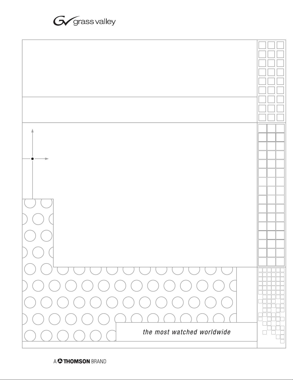
Module Placement in the 8900 Frame
There are ten slot locations in the 8900 Series video frame to accommodate
either analog or digital video modules. These are the left ten locations.
Refer to Figure 1 on page 9.
The two slots on the right are allocated for the power supplies. For additional information concerning the Power Supply module, refer to the
8900 Series Frames Instruction Manual.
The third slot from the right is allocated for the Frame Monitor or 8900NET
Network Interface module. These modules provide health monitoring and
control options.
Gecko
8 8920DMX Instruction Manual
Page 9
1.
2.
3.
Figure 1. 8900 Series Frame
Installation
8038-04r1
DA10
J1 J2
O
J3 J4
U
T
J5 J6
J7 J8
J9 J10
IN
DA9
J1 J2
J2
O
J3 J4
J4
U
T
J5 J6
J6
J7 J8
J8
J9 J10
IN
Any 8900 Module
Power
Supplies
Frame Monitor or
(only)
8900NET Network
Interface Module
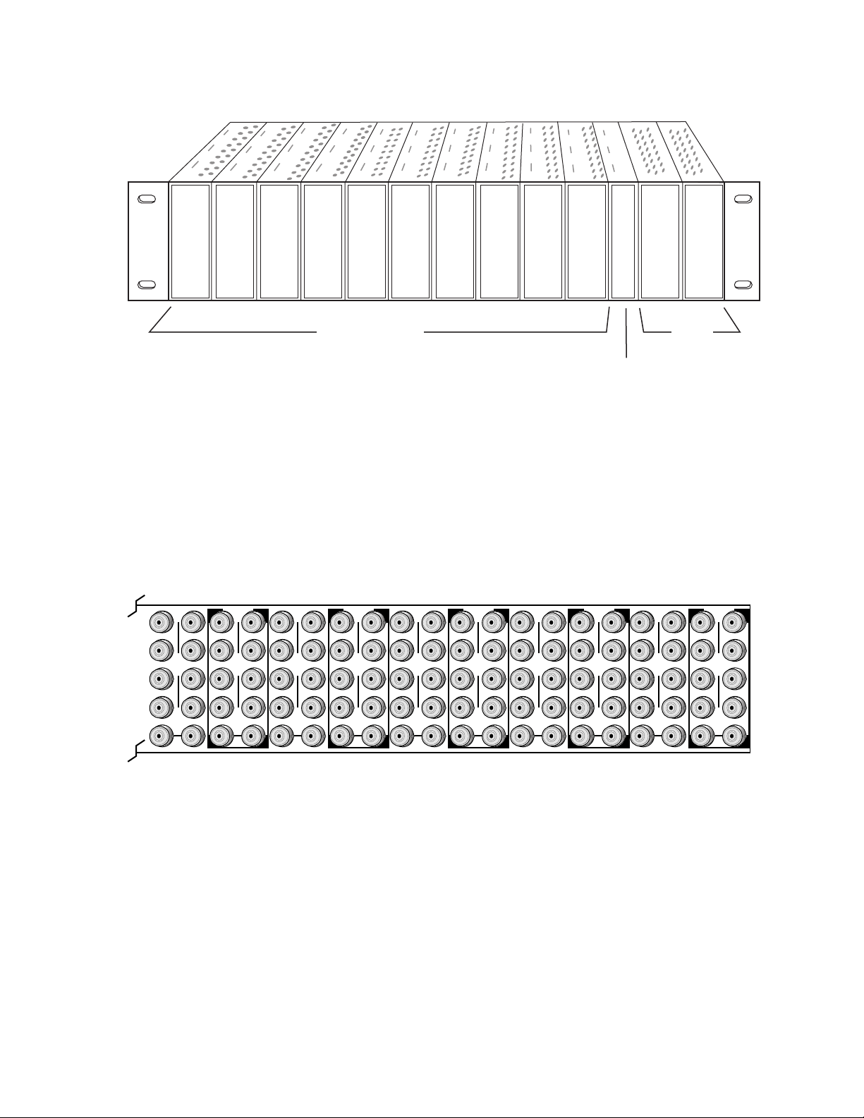
8900 modules are interchangeable within the module slots. There are 10
BNC connectors in each slot’s I/O group. The functional assignment of
each connector in a group is determined by the module that is placed in
that slot. The maximum number of modules an 8900 video frame can
accept is ten. Figure 2 illustrates the rear connector plate for an 8900 Series
video frame.
Figure 2. 8900 Series Frame Rear Connector
DA8
J1 J2
O
J3 J4
U
T
J5 J6
J7 J8
J9 J10
IN
DA7
J1 J2
J2
O
J3 J4
J4
U
T
J5 J6
J6
J7 J8
J8
J9 J10
IN
DA6
J1 J2
O
J3 J4
U
T
J5 J6
J7 J8
J9 J10
IN
DA5
J1 J2
J2
O
J3 J4
J4
U
T
J5 J6
J6
J7 J8
J8
J9 J10
IN
DA4
J1 J2
O
J3 J4
U
T
J5 J6
J7 J8
J9 J10
IN
DA3
J2
J1 J2
O
J4
J3 J4
U
T
J6
J5 J6
J8
J7 J8
J9 J10
IN
DA2
J1 J2
O
J3 J4
U
T
J5 J6
J7 J8
J9 J10
IN
DA1
J1 J2
O
J3 J4
U
T
J5 J6
J7 J8
J9 J10
IN
8038-03
To install a module in the frame:
Insert the module, connector end first, with the component side of the
module facing to the right and the ejector tab to the top.
Verify that the module connector seats properly against the backplane.
Press the ejector tab in to seat the module in place.
Note
At the back of this manual are overlay cards that can be placed over the rear
connector BNCs to identify the specific 8920DMX connector functions.
8920DMX Instruction Manual 9
Page 10

Installation
Cabling
Input
Outputs
The SD video stream is connected to the looping input BNC at J9 or J10. If
not looping the signal to other equipment, terminate the unused connector
into 75
Ω
.
The 8920DMX provides four SD output streams—J1 through J4. The destination equipment should have a 75
inputs that are terminated into 75
Ω
input impedance or loop through
Ω
.
For unbalanced AES/EBU audio outputs, connect cables to BNCs J5 and J6.
For applications requiring balanced audio outputs, use the terminal post
adapter shown in Figure 3 to connect up to two balanced AES/EBU output
cables. The adapter mounts on the plus and minus BNC pairs J5/J7 and
J6/J8. This adapter ships with the 8920DMX-110 model or can be ordered
separately if required.
Note
Figure 3.
AES
Output 1
Adaptor for balanced 110 Ω
outputs, connects to BNCs J5 - J8.
Jumpers JP12 – JP15 on the module circuit board must be set for the correct
audio output impedance (balanced 110 Ω or un balanced 75 Ω ). Refer to
Audio Output Impedance on page 14.
8920DMX
SD Output 1
SD Output 3
AES Output 1
unbalanced 75 Ω
Grass Valley
Adaptor
L+
J1
GND
L–
Input/Output Connectors
J3
J5
R+
J7
GND
R–
AES
Output 2
X
O
U
T
J9 J10
IN
SD Output 2
J2J1
SD Output 4
J4
AES Output 2
unbalanced 75 Ω
J6
J8
8038-02R2
Loop-through
SD Input
10 8920DMX Instruction Manual
Page 11

Power Up
Operation Indicator LEDs
Power Up
The LED indicators and configuration switches are illustrated in Figure 4.
Upon power-up, the green PWR LED should light and the yellow CONF
LED should light while the module initializes (less than 2 seconds).
With factory default configuration and a valid SD input containing
AES/EBU audio groups, the green PWR LED, an SD format LED (either
525 or 625), one or more Signal Present LEDs should be on. The appropriate
yellow Extract LED (G1 through G4) will indicate which audio group the
module is configured to extract.
Figure 4. Operation Indicator LEDs
FAULT (red)
COMM (yellow)
CONF (yellow)
PWR (green)
625 (green)
525 (green)
AES 1(green)
AES 2 (green)
24-bit LED
Audio G1 through G4
G1
Signal Present (green)
Audio G1 through G4
Extract (yellow)
G4
SW1 – Function Rotary Switch
SW2 – Select/Adjust Paddle Switch
EDH LED (yellow)
A red FAULT LED indicates an error situation and, with the other LEDs,
can indicate the operational conditions presented in Table 2. The table
describes signal output and LED indications for various input/reference
combinations and user settings.
Table 2. Indicator LEDs and Conditions Indicated
LED Indication Condition
FAULT
(red)
COMM
(yellow)
CONF
(yellow)
Off Normal operation.
On continuously Module has detected an internal fault. (Refer to Service on page 25.)
Flashing Configuration problems. Check inputs and settings. Missing video or group.
Off No activity on frame communication bus.
3 Quick Pulses Location Command received by the module from a remote control system.
Short flash Activity present on the frame communication bus.
Off Module is in normal operating mode.
On continuously Module is initializing, changing operating modes or updating firmware.
3 Quick Pulses Location Command received by the module from a remote control system.
8038_05
8920DMX Instruction Manual 11
Page 12

Power Up
Table 2. Indicator LEDs and Conditions Indicated - (continued)
LED Indication Condition
PWR
(green)
625
(green)
525
(green)
AES 1
(green)
AES 2
(green)
G1 Signal
Present
(green)
G2 Signal
Present
(green)
G3 Signal
Present
(green)
G4 Signal
Present
(green)
G1 Signal
Extract
(yellow)
G2 Signal
Extract
(yellow)
G3 Signal
Extract
(yellow)
G4 Signal
Extract
(yellow)
24b
(yellow)
EDH
(yellow)
Off No power to module or module’s DC/DC converter failed.
On continuously Normal operation, module is powered.
Off No video or standard is other than 625.
On continuously Valid 625 video signal is present.
Off No video or standard is other than 525.
On continuously Valid 525 video signal is present.
Off No valid AES 1 stream is present in selected group.
On continuously Valid 48 kHz AES 1 stream is present.
Off No valid AES 2 stream is present in selected group.
On continuously Valid 48 kHz AES 2 stream is present.
Off No audio present in channel G1.
On continuously Audio present in channel G1 and passing through.
Flashing Audio present in channel G1 and is being deleted.
Off No audio present in channel G2.
On continuously Audio present in channel G2 and passing through.
Flashing Audio present in channel G2 and is being deleted.
Off No audio present in channel G3.
On continuously Audio present in channel G3 and passing through.
Flashing Audio present in channel G3 and is being deleted.
Off No audio present in channel G4.
On continuously Audio present in channel G4 and passing through.
Flashing Audio present in channel G4 and is being deleted.
Off G1 audio will not be extracted.
On continuously G1 audio will be extracted.
Flashing G1 audio cannot be extracted because it does not exist in the input signal.
Off G2 audio will not be extracted.
On continuously G2 audio will be extracted.
Flashing G2 audio cannot be extracted because it does not exist in the input signal.
Off G3 audio will not be extracted.
On continuously G3 audio will be extracted.
Flashing G3 audio cannot be extracted because it does not exist in the input signal.
Off G4 audio will not be extracted.
On continuously G4 audio will be extracted.
Flashing G4 audio cannot be extracted because it does not exist in the input signal.
Off Encoding is 20-bit.
On continuously Encoding is 24-bit.
Off No error detected.
On EDH error has been detected.
12 8920DMX Instruction Manual
Page 13

Configuration
Configuration
The 8920DMX module can be configured locally using onboard switches or
remotely using the 8900NET network interface.
Configuration and adjustment items for the 8920DMX include:
•Remote control lockout (with onboard jumper JP10),
•AES balanced 110
onboard jumpers),
•Audio channel extraction/deletion,
• Source of CRC/UVC generation, and
• Setup save and recall.
Refer to the following sections for configuration instructions:
•Configuration Summary (page 13)
•Onboard Module Configuration (page 14)
•Remote Control and Monitoring (page 16)
Configuration Summary
The 8920DMX module accepts an SD video input and can be configured by
the user to extract and pass or delete any one of four audio groups present
in the SD signal. This is done with the Audio Group Management controls.
The extracted audio group can be accessed at either AES balanced 110
unbalanced 75
Ω or unbalanced 75 Ω output (configured with
Ω
outputs (jumper selected) from the module.
Ω
or
Note
The module also provides a control for selecting CRC/UVC generation.
Normally, this control should be set to external. However, because of limitations in the module’s hardware, if the AES 1 and AES 2 channels in an
audio group are out of time (> 1 audio clock), the CRC/UVC on the AES 2
output gets corrupted. In this case, CRC/UVC generation should be set to
internal. In this mode, the module strips the externally generated CRC
from the two audio streams and inserts an internally generated CRC/UVC,
avoiding possible CRC errors downstream.
Note
8920DMX Instruction Manual 13
The 8920DMX extracts and deletes only one audio group. To change more
than one audio group in the SD stream, you can loop the input to multiple
modules and configure each module to manipulate one of the four groups
With CRC/UVC generation set to internal, status bits on the AES output are
set to 48 kHz Professional (synchronous) and user bits are set to zero.
Page 14

Configuration
Onboard Module Configuration
The 8920DMX module can be locally configured using the jumpers, the
rotary switch, and the paddle switch shown in Figure 5. These components
perform the following:
• Jumpers – set control mode for Local only or Remote and Local, and
select audio output type and impedance.
• Function (rotary) switch – selects a desired configuration parameter (0
through 9, A through F), although not all positions are used.
•SW1 (paddle) switch – initiates a configuration parameter selection.
• CONF (configuring) LED – when on, indicates the module is initializing or processing configuration information.
Remote Control Lockout
When a jumper is placed across pins 2 and 3 of jumper block JP10 (see
Figure 5), module output mode settings are adjustable from the Local
on-board switches only. To have both Local and Remote access, set the
jumper across pins 1 and 2.
Audio Output Impedance
The desired audio type and output impedance must be selected as balanced 110
Ω or unbalanced 75 Ω
with jumpers JP12 and JP13 (AES 1) and
JP13 and JP15 (AES 2) shown in Figure 5.
Figure 5. Module Configuration Switches and LEDs
Audio Output Impedance
CONF (yellow)
JP10
SW1 – Function Rotary Switch
SW2 – Selection Paddle Switch
Remote Control Lockout
jumper across these pins
LOCAL –
3
2
1
JP10
locks out remote control
REMOTE –
jumper across these pins
enables remote and
local control
AES 1
AES 2
JP12
110 Ω
bal.
JP13
110 Ω
bal.
JP14
110 Ω
bal.
JP15
110 Ω
bal.
75 Ω unbal.
75 Ω unbal.
75 Ω unbal.
75 Ω unbal.
JP12
JP13
JP14
JP15
8038_06r1
14 8920DMX Instruction Manual
Page 15

Local Onboard Configuration Settings
The 8920DMX can be configured using the rotary switch shown in Figure 5
on page 14 to access the configuration items shown in Table 3. To make a
configuration setting, rotate the switch to the desired configuration parameter. Use the paddle switch to select either the switch Up or switch Down
setting.
Table 3. 8950DAC Configuration Functions
Configuration
Function
Switch
0----Inactive position
1----Not Used
2 St 1/2 from G1 and pass G1 N/A Extracts and passes AES1 and AES2 from Group 1, if signals are present
3 St 1/2 from G2 and pass G2 N/A Extracts and passes AES1 and AES2 from Group 2, if signals are present
4 St 1/2 from G3 and pass G3 N/A Extracts and passes AES1 and AES2 from Group 3, if signals are present
5 St 1/2 from G4 and pass G4 N/A Extracts and passes AES1 and AES2 from Group 4, if signals are present
6 St 1/2 from G1 and delete G1 Same as Setting 2/Up Extracts and removes or passes G1 AES/EBU in the D1 output stream
7 St 1/2 from G2 and delete G2 Same as Setting 3/Up Extracts and removes or passes G2 AES/EBU in the D1 output stream
8 St 1/2 from G3 and delete G3 Same as Setting 4/Up Extracts and removes or passes G3 AES/EBU in the D1 output stream
9 St 1/2 from G4 and delete G4 Same as Setting 5/Up Extracts and removes or passes G4 AES/EBU in the D1 output stream
A-D -- -- Not used
E CRC from input signal CRC internally generated
F Recall Store Store or recall user settings
Paddle
Switch Up
Note
Paddle
Switch Down
Select source of CRC and UVC generation. Internal inserts internally generated CRC/UVC into both streams
Function Description
Currently, when an audio group is extracted and deleted from the SD output,
the demultiplexing chip does not revise the CRC checksum included in the
output signal. As a result, a CRC error may be reported by downstream
devices.
Table 4 provides the possible input conditions and the output condition
that result when the rotary switch is set to extract and pass G1 (position 2),
G2 (position 3), G3 (position 4) or G4 (position 5) or extract and delete the
selected group.
Table 4. Possible Operating Conditions
SD Video
Input Condition
Present Present
Present Not Present If no audio group exists in incoming video, AES output will be digital silence.
Not Present Not Present If no video or audio input, video output will be random noise and audio output will be digital silence.
Present Present
AES/EBU Audio
Input Condition
Output Condition
If G(n) exists in incoming video, AES1 and AES2 will be extracted, and unchanged video will be
passed. If G(n) does not exist in the incoming video, the AES output will be digital silence.
If extracted group has been selected to be deleted (rotary switch settings 6 – 9), extracted audio group
will be deleted from incoming video stream. (See
Note
above concerning CRC errors.)
8920DMX Instruction Manual 15
Page 16

Configuration
Remote Configuration and Monitoring
8920DMX configuration and monitoring can be performed remotely using
the 8900NET interface in 8900TF or TFN frames (see Figure 6). This section
describes the GUI access to the module configuration functions. Refer to
the
8900NET Network Interface Module Instruction Manual
for information on
setting up and operating the 8900 frame network.
For remote access, make sure the jumper block on the module is set for both
Local and Remote access (Figure 5 on page 14).
Note
Figure 6. 8900NET GUI
The Links section lists the frame and its current modules. The selected link's Status
page is first displayed and the sub-list of links for the selection is opened. The sub-list
allows you to select a particular information page for the selected device.
The physical appearance of the menu displays shown in this manual represent the use of a particular platform, browser and version of 8900NET
module software. They are provided for reference only. Displays will differ
depending on the type of platform and browser you are using and the version
of the 8900NET software installed in your system.
Content display section displays the information page
for the selected frame or module (frame slot icons are also
active links).
Refresh button for manual
update of page
Online Manual Link
8038_08
16 8920DMX Instruction Manual
Page 17

Configuration
The 8900 modules can be addressed by clicking on a specific module icon
in the frame status display or on a module name or slot number in the link
list on the left.
Use the
ware version 3.0 and later).
The
pdf format. Link configuration is done on the Frame Configuration page.
For information on status and fault monitoring and reporting shown on the
Status page, refer to Status Monitoring on page 22.
Refresh button to update the display (available with 8900NET soft-
Online Manual Link button can be set up to link to the documentation in
Module Links and Displays
The 8900 GUI provides the following links and displays for the 8920DMX
module (refer to Figure 7):
• Status – reports module operational status and properties (part and
version numbers),
• Signal configuration displays for setting up module parameters,
• Slot Config – module configuration information (location and user
assigned names), and
• Software Update – allows software download via the 8900NET module
when available.
Note Refer to the latest Release Notes for this module on the Grass Valley website
at http://www.thomsongrassvalley.com for complete details on updating
software.
The Status, Slot Config, and Software Update displays are described in
detail in the 8900NET manual. Some functions listed may not be supported
by a particular module. These will be indicated as not supported.
Refer to Signal Configuration Displays in the next section for complete details
on setting the module parameters.
Figure 7. 8920MUX Module Configuration Display Links
Status Display
Signal Configuration Displays
Slot Configuration Display
Software Update Display
8920DMX Instruction Manual 17
Page 18

Configuration
Signal Configuration Displays
This section discusses in detail the signal configuration displays used to
setup the 8920DMX module output configuration.
Use
This
Link
Audio Group Management
The Audio Group Management display (see Figure 8) allows you to
perform the following functions:
• Select the Output action for the module (Extract and pass or delete one
of four audio groups to the SD output),
•Choose the source of CRC/UVC generation from
generated from input signal) or
nally), and
• Enable or disable SD input reporting for applications where this
reporting is not desirable or required. When set to Disabled, the SD
Input graphic on the Status page will be gray, showing this signal as not
monitored. See Status Monitoring on page 22.
Click the
The status reporting section of the display provides monitoring of:
•Audio groups present in the SD input,
• Status of the group extract/pass/delete action, and
•Audio groups present in the SD output.
Apply button to activate a selection.
Internal (CRC/UVC is generated inter-
External (CRC/UVC is
CAUTION When monitoring the status of the signal configuration, be aware that this
page is a static display and requires manual refresh. Changing SD input
upstream can cause changes to the 8920DMX output that will not be reported
until status refresh is activated. To refresh the status information click on the
page link or Refresh button (8900NET software version 3.0 and later).
18 8920DMX Instruction Manual
Page 19

Figure 8. Audio Group Management Display
Configuration
8920DMX Instruction Manual 19
Page 20

Configuration
Use
This
Link
Save/Recall User Settings
The Recall/Save User Settings display (see Figure 9) allows you to set the
following parameters:
•Recall the saved User Settings (
• Save the currently selected settings for the entire module as User Settings (
Save User Settings), or
Recall User Setup),
•Recall factory default settings (
Figure 9. User Settings Display
Recall Fact Defaults).
20 8920DMX Instruction Manual
Page 21

Specifications
Specifications
Table 5. 8920ADC Specifications
Parameter Value
SDI Input
Number of inputs 1 loop-through
Connector type BNC
Input impedance High impedance
Signal type SMPTE 259M serial 10-bit 4:2:2 component video, 525 or 625
Signal level SDI
Return loss >15 dB, 5 to 270 MHz
Cable equalization Automatic for <984 ft (300 m)
SDI Output
Number of outputs 4
Signal type SMPTE 259M
Return loss >15 dB, 5 to 270 MHz
Output impedance 75 Ω
Connector type BNC
Error checking EDH embedded
Digital Audio Output
Number of outputs 2 (AES1, AES2)
Signal type AES/EBU
Connector type One 75 Ω BNC per output
Using adapter, one 110 Ω terminal block per output
Output impedance 75 Ω or 110 Ω, jumper selected
Sampling rate 48 kHz sample rate 20- or 24-bit
Signal level 1 V peak to peak
Signal Processing Functions
Electrical length 4.2 µs
Audio format 48 kHz synchronous audio formatted per proposed SMPTE standard
“Formatting AES/EBU audio and auxiliary data into digital video ancil-
lary data space.”
Interchannel crosstalk ≤100 dB, 20 Hz - 20 kHz
Environmental
Frame temperature range 0 to 40 degrees C
Operating humidity range 0 to 90% non-condensing
Non-operating temperature -10 to 70 degrees C
Mechanical
Frame type Gecko 8900 BNC/Video frame
Power Requirements
Supply voltage ±12 V
Power consumption < 4.5 Watts
8920DMX Instruction Manual 21
Page 22

Status Monitoring
Status Monitoring
This section provides a summary of status monitoring and reporting for a
Gecko 8900 Series system. It also summarizes what status items are
reported and how to enable/disable reporting of each item. There are a
number of ways to monitor status of modules, power supplies, fans and
other status items depending on the method of monitoring being used.
8900 Frame status will report the following items:
• Power supply health,
• Status of fans in the frame front cover,
•Temperature,
•Module health, and
• Frame bus status.
Module health status will report the following items:
• Internal module state (and state of submodule or options enabled)
including configuration errors (warning), internal faults, and normal
operation (Pass).
LEDs
• Signal input states including valid/present (pass), not present or
invalid (warning), not monitored, and not available (no signal inputs).
•Reference input states including locked/valid (pass), not
locked/invalid (warning), and not monitored.
• Signal output states with reporting functionality (reference output).
LEDs on modules in the frame and on the front of the 8900TF/TFN frames
indicate status of the frame and the installed power supplies, fans in the
front covers, and modules. (The 8900TX-V/A frames have no LED indicators on the front cover.)
When a red FAULT LED is lit on a frame front cover, the fault will also be
reported on the 8900NET or Frame Monitor module. The LEDs on the front
of these modules can then be read to determine the following fault conditions:
• Power Supply 1 and 2 health,
• Fan rotation status,
• Frame over-temperature condition,
• Frame Bus fault (8900NET only), and
•Module health bus.
22 8920DMX Instruction Manual
Page 23

Frame Alarm
Status Monitoring
In general, LED colors used on the frame and modules indicate:
•Green = normal operation, (Pass) or signal present, module locked.
•Red – On continuously = fault condition, flashing = configuration error.
•Yellow – On continuously = active condition (configuration mode or
communication), flashing in sequence = module locator function.
Status LEDs for this module are described in Operation Indicator LEDs on
page 11. LEDs for the 8900NET module are described in the 8900NET
Network Interface Instruction Manual.
A Frame Alarm connection is available on pins 8 and 9 of the RS-232 connector on the rear of 8900 frame (Frame Monitor or 8900NET Network
Interface module required). This will report any of the status items enabled
with the 8900NET or Frame Monitor module configuration DIP switch.
Connection and use of the Frame Alarm is covered in detail in the 8900NET
Network Interface Instruction Manual.
Web Browser Interface
When the 8900NET module is installed in the frame, a web browser GUI
can indicate frame and module status on the following web pages:
• Frame Status page – reports overall frame and module status in graph-
ical and text formats.
•Module Status page – shows specific input and reference signal status
to the module along with enabled options and module versions.
•A Status LED icon on each web page to report communication status
for the frame slot and acts as a link to the Status page where warnings
and faults are displayed (8900NET version 3.0 or later).
In general, graphics and text colors used indicate the following:
•Green = Pass – signal or reference present, no problems detected.
•Red = Fault – fault condition.
•Yellow = Warning – signal is absent, has errors, or is mis-configured.
•Gray = Not monitored (older 8900 module).
•White = Not present.
Status reporting for the frame is enabled or disabled with the configuration
DIP switches on the 8900NET module. Most module status reporting items
can be enabled or disabled on individual configuration web pages.
8920DMX Instruction Manual 23
Page 24

Status Monitoring
SNMP Reporting
The Gecko 8900 Series system uses the Simple Network Monitoring Protocol (SNMP) internet standard for reporting status information to remote
monitoring stations. When SNMP Agent software is installed on the
8900NET module, enabled status reports are sent to an SNMP Manager
such as the Grass Valley’s NetCentral application.
There are both hardware and software report enable switches for each
report. Both must be enabled for the report to be sent. Software report
switches are set on the 8900NET Configuration page for the Frame, the
8900NET module, and each module slot. Refer to the 8900NET Network
Interface Instruction Manual for installation instructions.
24 8920DMX Instruction Manual
Page 25

Service
Service
The 8920DMX modules make extensive use of surface-mount technology
and programmed parts to achieve compact size and adherence to
demanding technical specifications. Circuit modules should not be serviced in the field unless directed by Customer Service.
If your module is not operating correctly, proceed as follows:
•Check frame and module power and signal present LEDs. If module
power is not present, check fuse F1 (see Figure 10).
•Check for presence and quality of input signals.
•Verify that source equipment is operating correctly.
•Check cable connections.
•Check output connections for correct I/O mapping (correct input con-
nector is used for the corresponding channel output).
• If the red FAULT LED is on, reseat module to reset. If FAULT does not
go out, module has internal problem and will need to be replaced.
Refer to Figure 4 for the location of PWR LED and Table 2 on page 11 for
proper LED indications.
If the module is still not operating correctly, replace it with a known good
spare and return the faulty module to a designated Grass Valley repair
depot. Call your Grass Valley representative for depot location.
Refer to the Contacting Grass Valley at the front of this document for the
Grass Valley Customer Support Information number.
Figure 10. 8920DMX Module Fuse Location
JP12
JP13
JP10
JP14
JP15
F1
8038_07
Fuse: 2 A FAST, 125 V
8920DMX Instruction Manual 25
Page 26

Functional Description
Functional Description
The 8920DMX is able to extract one existing audio group from the ancillary
data of a SD video stream by using the group’s ID. The group can then be
either passed or deleted from the SD output. Refer to the block diagram in
Figure 11.
Figure 11. 8920DMX Block Diagram
Serial
Digital
Video
Input
Amplifier
& Equalizer
G1 delete
G2 delete
G3 delete
G4 delete
Audio G4 present
Audio G3 present
Audio G2 present
Audio G1 present
625 Mode
525 Mode
2nd Function
Network Interface CPU
FP
LED
Display
Clock
Ex.
Serial to
Parallel
Converter
27 Mhz,
64 aFS,
128 aFS
Phase
Lock
Loop
Reset
Local/remote
Jumper
Control
Bus Control
FPGA
Audio &
Video
Clock
Synth.
DeMUX
Switches
Rotary
Switch
DIP
Parallel
to Serial
Converter
User
Setup
Switch
Logic
Serial Digital & Audio
Output Driver
AES Output Stereo 1
AES Output Stereo 2
Serial
Digital
Outputs
Audio
Out 1
Audio
Out 2
Fault
Comm
Conf
Pwr
8038-01
Video Inputs
The serial input and deserializer are a standard chip set for receiving and
converting a serial digital video stream into a 10-bit parallel 601 digital
video signal.
26 8920DMX Instruction Manual
Page 27

Functional Description
Input Equalizing Amplifier
The equalizing amplifier senses the voltage through its differential inputs.
It DC isolates the inputs and helps reduce the effect of stray capacitance
which lowers the impedance of the termination as frequency increases. The
differential input also improves the performance of the 8920DMX in the
presence of common mode hum and noise.
Clock Regenerator
The reclock stage is used to set mode and display the data rate. The Phase
Lock Loop circuit (PLL) uses a voltage controlled oscillator (VCO) to lock
to the clock of the incoming data.
Serial to Parallel Converter and EDH/EDA Error Processor
The serial to Parallel converter converts serial data stream to the parallel
data using the regenerated clock. Deserialized data passes through the
EDH processor. The EDH processor checks for possible data or bit errors in
the incoming data.
27Mhz PLL
From the incoming 27 MHz clock, the PLL generates the internal 27 MHz
and an approximate 27 MHz free running clock used if no input signal is
present.
Field Programmable Gate Array (FPGA)
The FPGA contains two independent blocks:
• 6.144 Mhz clock generator
•CPU interface
Using the DDS (Direct Digital Synthesis) method, the clock generator
inside the FPGA, together with the D-to-A converter and fast comparator
generates a 6.144 Mhz AES3 carrier clock from the incoming 27 Mhz.
The CPU interface provides connection between the board hardware and
CPU. From the FPGA, the CPU reads out information about current board
status and writes back user commands to the hardware.
8920DMX Instruction Manual 27
Page 28

Functional Description
Demultiplexer
Parallel to Serial Converter
CPU Embedded Processor
The demultiplexer is a single chip solution for demultiplexing of digital
audio channels out of digital video signals. It supports the demultiplexing
of 20- or 24-bit synchronous audio data with a 48 kHz sample rate. The
demultiplexer supports video standards with rates from 143 Mb/s to 540
Mb/s.
The 8920DMX uses a standard 10-bit 270 Mbs Serializer.
The embedded processor provides the interface between the user and all
the processing logic inside 8920DMX and communication between a host
processor and the 8920DMX.
The CPU contains:
Power Supply
• FLASH memory (stores data for FPGA programming
and configuration),
•Address decoder,
•Address Latch,
• Extended address register for FLASH memory,
• EEPROM (stores calibration and user setup data),
•Network interface, and
• ISP voltage regulator.
From the external source +12 V, the on-board supply provides +5 V, -5 V
and +3.3 V for the 8920DMX. The power supply uses a monolithic
switching power supply operating in Buck mode. Buck mode switching
regulators are used to generate a lower voltage from higher voltage input.
If the supply ever activates its protective crow bar diode, a high current will
be developed and the input fuse, F1 will blow.
28 8920DMX Instruction Manual
Page 29

Index
Numerics
8920DMX
about
7
features 7
specifications 21
A
audio group management 15, 18
audio outputs
impedance settings
C
COMM LED 11
configuration
factory default
jumpers 14
LEDs 14
local onboard controls 15
remote control 16
switches 14
connectors 9
output 10
CRC and UVC generation
local setting
overview 13
remote control 18
11
15
10, 14
Fault LED 11, 25
format setup 15
frame
cooling capacity
module capacity 8
power capacity 8
slot locations 8
status reporting 22
Frame Status page 16, 23
frequently asked questions 2
8
G
Grass Valley
website
GUI 16
2
I
impedance
jumper settings
inputs
reference
11
10, 14
L
links 17
M
D
documentation online
Online Manual Link
web site 2
E
enable SNMP 24
17
module
install
9
placement 8
replacement 25
slots 9
module health status 22
Module Status page 23
monitoring 16
F
FAQ database 2
8920DMX Instruction Manual 29
Page 30

Index
N
network 16
O
online documentation
Online Manual Link
web site 2
operational conditions
LED indications
outputs
audio
10
connectors 10
termination 10
overlay 9
11
P
power requirements 21
R
17
W
web site
documentation
FAQ database 2
Grass Valley 2
software download 2
2
reference inputs 11
remote configuration
audio groups
CRC and UVC generation 18
insert/replace 18
pass/delete 18
user settings 20
remote configuration and monitoring 16
report enable switches 24
18
S
SD input reporting
enabling or disabling
SNMP reporting 24
software download from web 2
software updating 17
specifications 21
status monitoring 22
status reporting 18
18
T
troubleshooting 25
30 8920DMX Instruction Manual
 Loading...