

Page 1

8920DAC
AES/EBU TO ANALOG AUDIO CONVERTER
Instruction Manual
071-0614-02
FIRST PRINTING: JULY 1999
REVISED PRINTING: SEPTEMBER 2000
2.0software release
Page 2

Contacting Grass Valley Group
Region Voice Fax Address Web Site
North America (800) 547-8949
530-478-4148
Pacific Operations +852-2585-6688
Support: 852-2585-6579
U.K., Europe, Asia, Middle East +44 1753 218 777 +44 1753 218 757
France +33 1 45 29 73 00
Germany +49 221 1791 234 +49 221 1791 235
Copyright © Grass Valley Group. All rights reserved.
This document may not be copied, in whole or in part, or otherwise reproduced, except as specifically
permitted under U.S. copyright law, without the prior written consent of Grass Valley Group, P.O. Box
599000, Nevada City, CA 95959-7900 USA. GRASS VALLEY GROUP is a registered trademark and
Grass Valley is a trademark of Grass Valley Group. All registered trademarks and trademarks are property of their respective holders. Grass Valley Group products are covered by U.S. and foreign patents,
issued and pending. Product options and specifications subject to change without notice. The information in this manual is furnished for informational use only, is subject to change without notice, and
should not be construed as a commitment by Grass Valley Group. Grass Valley Group assumes no responsibility or liability for any errors or inaccuracies that may appear in this publication.
(530) 478-3347 Grass Valley Group
+852-2802-2996
P.O. Box 599000
Nevada City, CA 95959-7900
USA
www.grassvalleygroup.com
Page 3

Contents
Preface
About This Manual . . . . . . . . . . . . . . . . . . . . . . . . . . . . . . . . . . . . . . . . . . . . . . . . . . . . . v
8920DAC AES/EBU to Analog Audio Converter
Introduction . . . . . . . . . . . . . . . . . . . . . . . . . . . . . . . . . . . . . . . . . . . . . . . . . . . . . . . . . . . 1
Installation . . . . . . . . . . . . . . . . . . . . . . . . . . . . . . . . . . . . . . . . . . . . . . . . . . . . . . . . . . . . 2
Module Placement in the 8900 Frame. . . . . . . . . . . . . . . . . . . . . . . . . . . . . . . . . . . . 2
Frame Capacity . . . . . . . . . . . . . . . . . . . . . . . . . . . . . . . . . . . . . . . . . . . . . . . . . . . . . . 3
Cabling . . . . . . . . . . . . . . . . . . . . . . . . . . . . . . . . . . . . . . . . . . . . . . . . . . . . . . . . . . . . . 4
Loop-through Input. . . . . . . . . . . . . . . . . . . . . . . . . . . . . . . . . . . . . . . . . . . . . . . . . 4
Outputs . . . . . . . . . . . . . . . . . . . . . . . . . . . . . . . . . . . . . . . . . . . . . . . . . . . . . . . . . . . 4
Power Up . . . . . . . . . . . . . . . . . . . . . . . . . . . . . . . . . . . . . . . . . . . . . . . . . . . . . . . . . . . . . 5
Operation Indicator LEDs . . . . . . . . . . . . . . . . . . . . . . . . . . . . . . . . . . . . . . . . . . . . . 5
Configuration. . . . . . . . . . . . . . . . . . . . . . . . . . . . . . . . . . . . . . . . . . . . . . . . . . . . . . . . . . 8
Local Onboard Module Configuration. . . . . . . . . . . . . . . . . . . . . . . . . . . . . . . . . . . 8
Configuring Output Mode . . . . . . . . . . . . . . . . . . . . . . . . . . . . . . . . . . . . . . . . . . . 9
Level Adjustment. . . . . . . . . . . . . . . . . . . . . . . . . . . . . . . . . . . . . . . . . . . . . . . . . . 10
20/24-bit DAC Operation. . . . . . . . . . . . . . . . . . . . . . . . . . . . . . . . . . . . . . . . . . . 10
Remote Control Lockout. . . . . . . . . . . . . . . . . . . . . . . . . . . . . . . . . . . . . . . . . . . . 10
Remote Configuration and Monitoring . . . . . . . . . . . . . . . . . . . . . . . . . . . . . . . . . 11
Module Configuration Displays . . . . . . . . . . . . . . . . . . . . . . . . . . . . . . . . . . . . . 12
Software Update Displays . . . . . . . . . . . . . . . . . . . . . . . . . . . . . . . . . . . . . . . . . . 12
Signal Configuration Displays. . . . . . . . . . . . . . . . . . . . . . . . . . . . . . . . . . . . . . . 12
Specifications . . . . . . . . . . . . . . . . . . . . . . . . . . . . . . . . . . . . . . . . . . . . . . . . . . . . . . . . . 15
Service. . . . . . . . . . . . . . . . . . . . . . . . . . . . . . . . . . . . . . . . . . . . . . . . . . . . . . . . . . . . . . . 16
Functional Description . . . . . . . . . . . . . . . . . . . . . . . . . . . . . . . . . . . . . . . . . . . . . . . . . 17
Digital Input . . . . . . . . . . . . . . . . . . . . . . . . . . . . . . . . . . . . . . . . . . . . . . . . . . . . . . . . 17
Control and Routing FPGA . . . . . . . . . . . . . . . . . . . . . . . . . . . . . . . . . . . . . . . . . . . 18
CPU (Controller) . . . . . . . . . . . . . . . . . . . . . . . . . . . . . . . . . . . . . . . . . . . . . . . . . . . . 18
Digital/Analog Converter (DAC), Filter, Gain, and Output Stages . . . . . . . . . 18
Regulator. . . . . . . . . . . . . . . . . . . . . . . . . . . . . . . . . . . . . . . . . . . . . . . . . . . . . . . . . . . 19
Index
8920DAC Instruction Manual iii
Page 4

Contents
iv 8920DAC Instruction Manual
Page 5

Preface
About This Manual
This manual describes the features of a specific module of the 8900 Series
Modular Products family. As part of this module family, it is subject to
Safety and Regulatory Compliance described in the 8900 Series frame and
power supply documentation (see the
Instruction Manual
8900TX/8900TF/8900TFN Frames
).
8920DAC Instruction Manual v
Page 6

Preface
vi 8920DAC Instruction Manual
Page 7

8920DAC AES/EBU to Analog Audio Converter
Introduction
The 8920DAC converts digital audio to analog audio and provides true 20bit performance. Its various modes can modify the outgoing signal to
provide channel swapping, channel summing, tones, and phase inversion.
When used in an 8900 frame supporting network control, the 8920DAC
supports remote mode selection. The module uses 24-bit delta-sigma
digital-to-analog converters (DACs) with 128 times over-sampling and
noise shaping which offer superior performance with lower idle tones, and
excellent sonic performance and resolution.
8920DAC features include:
■
Support for 32 kHz, 44.1 kHz, and 48 kHz sampling rates
■
Jumper selectable 20-bit or 24-bit DAC mode
■
One 75
One pair of balanced analog outputs available on terminal block
■
outputs using BNC adapter board
■
Input sampling frequency, emphasis, and error LED indicators
Output range selection from +14 dBu to +24 dBu with jumper selectable
■
maximum level
Ω
loop-through AES-3id/EBU input
■
Channel level control using an on-board, multi-turn trim potentiometer
■
Auto detection of emphasis and engagement of de-emphasis to flatten
frequency response
Module is part of the 8900 family of audio and video modules
■
■
Supports remote control in 8900 networking frames
■
Offers remote control lockout using an on-board jumper
8920DAC Instruction Manual 1
Page 8
8920DAC AES/EBU to Analog Audio Converter
Installation
Installation of the 8920DAC module is a process of:
Placing the module in the desired frame slot,
■
■
Cabling and terminating signal ports, and
■
Configuring the module.
The 8920DAC module can be plugged in and removed from an 8900 Series
frame with power on. When power is applied to the module, LED indica-
tors reflect the initialization process (see Power Up on page 5 ).
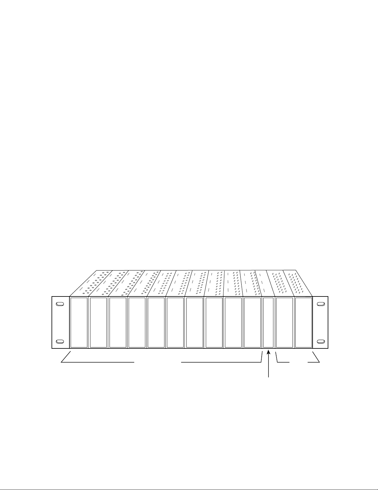
Module Placement in the 8900 Frame
There are ten cell locations in the frame to accommodate either analog or
digital modules. These are the left ten locations. Refer to Figure 1.
The two cells on the right are allocated for the power supplies. For addi-
tional information concerning the Power Supply module, refer to the 8900
Power Supply manual.
The third cell from the right is allocated for the Frame Monitor or Network
Interface controller modules. These modules provide health monitoring
and control options.
Figure 1. 8900 Series Frame
Any 8900 Module
Frame Monitor Module or
Network Interface Module
Power
Supplies
(only)
0614-04r1
2 8920DAC Instruction Manual
Page 9
1.
3.
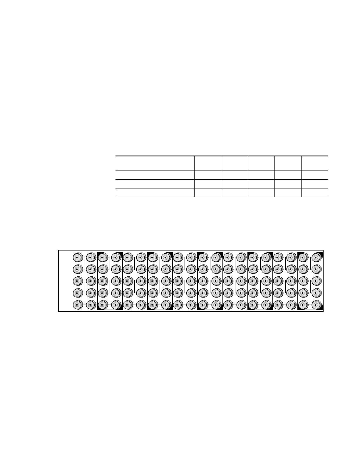
8900 modules are interchangeable within the module cells. There are 10
BNC connectors in each cell’s I/O group. The functional assignment of
each connector in a group is determined by the module that is placed in
that cell. The maximum number of modules an 8900 frame can accept is ten.
Figure 2 illustrates the rear connector plate for an 8900 Series frame.
Frame Capacity
The maximum number of 8900 modules allowed in a frame is determined
by frame cooling capacity. Table 1 provides the power capacity, cooling
capacity, and maximum module count for the 8920DAC in each frame type.
Table 1. Power, Cooling, and Module Capacity of 8900 Frames
Power (W) 60 60 100 100 100
Recommended Module Cooling (W) 30 60 30 90 90
8920DAC Modules 10 10 10 10 10
Capacity Calculated
8900T2
Frame
8900T2-F
Frame
8900TX
Frame
8900TF
Frame
Installation
8900TFN
Frame
DA10
J1 J2
O
J3 J4
U
T
J5 J6
J7 J8
J9 J10
IN
DA9
J1 J2
J2
O
J3 J4
J4
U
T
J5 J6
J6
J7 J8
J8
J9 J10
IN
Note
Module capacity figures assume no other modules are in the frame. If the
maximum number of modules a frame can handle is less than ten, provide as
much space between the modules as possible.
Figure 2. 8900 Series Frame Rear Connectors
DA8
J1 J2
O
J3 J4
U
T
J5 J6
J7 J8
J9 J10
IN
DA7
J1 J2
J2
O
J3 J4
J4
U
T
J5 J6
J6
J7 J8
J8
J9 J10
IN
DA6
J1 J2
O
J3 J4
U
T
J5 J6
J7 J8
J9 J10
IN
DA5
J1 J2
J2
O
J3 J4
J4
U
T
J5 J6
J6
J7 J8
J8
J9 J10
IN
DA4
J1 J2
O
J3 J4
U
T
J5 J6
J7 J8
J9 J10
IN
DA3
J2
J1 J2
O
J4
J3 J4
U
T
J6
J5 J6
J8
J7 J8
J9 J10
IN
DA2
J1 J2
O
J3 J4
U
T
J5 J6
J7 J8
J9 J10
IN
DA1
J1 J2
O
J3 J4
U
T
J5 J6
J7 J8
J9 J10
IN
8900 modules can be inserted and removed while the frame is powered. To
install a module in the frame:
Insert the module, connector end first, with the component side of the
module facing to the right and the ejector tab to the top.
2.
Verify that the module connector seats properly against the backplane.
0614-03
Press the ejector tab in to seat the module in place.
8920DAC Instruction Manual 3
Page 10

8920DAC AES/EBU to Analog Audio Converter
Cabling
Note
At the back of this manual are overlay cards that can be placed over the rear
connector BNCs to identify the specific 8920DAC connector functions.
Loop-through Input
Connect an input signal to one of the loop-through input connectors, J9 or
J10 (see Figure 3). The 8920DAC input will accept AES-3id/EBU audio. Terminate the unused connector into 75 Ω if the signal is not looped to other
equipment.
Figure 3.
J1
J3
J5
L+
GND
L–
8920DAC
Grass Valley
DAx
Adaptor
O
Input/Output Connectors
R+
J2
J2
GND
R–
U
T
J4
J6
J4
J6
Analog balanced
output adapter
Not Used
AES/EBU
Loopthrough Input
Outputs
J8
J7
J9 J10
IN
J8
0614-02
The 8920DAC provides one stereo analog, differential pair output through
the plug-in adapter connected to BNCs J1- J4.
4 8920DAC Instruction Manual
Page 11

Power Up
Operation Indicator LEDs
Power Up
The front LED indicators and configuration switches are illustrated in
Figure 4. Upon power-up, the green PWR LED should light and the yellow
CONF LED should illuminate for the duration of module initialization.
With factory default configuration and a valid input signal connected, the
green PWR LED should be on and the yellow REM OVER LED should be
off. (Refer to Table 2 on page 6 and Table 3 on page 7 to see a complete list
of possible operating conditions and the resulting indicator status.)
Audio input presence is indicated by the 32, 44.1, or 48 LED which indicates the corresponding input signal sample rate has been detected. The
REM OVER LED indicates that the Function Switch is being overridden by
remote control.
Figure 4. LEDs and Configuration Switches
Ejector Tab
FAULT – Red diagnostic LED is off during normal operation
COMM – Yellow LED on during remote control communication
CONF – Yellow LED on when module is initializing or
processing control data
PWR – Green diagnostic LED on indicates power OK
32 – Green LED on indicates active sample rate
44.1 – Green LED on indicates active sample rate
48 – Green LED on indicates active sample rate
REM OVER – Yellow LED on indicates local switches and
jumper settings are overridden by remote control
5
6
4
7
3
8
2
9
1
A
0
B
F
C
E
D
16-position Rotary switch
selects output mode
EMPH – Yellow LED on indicates module is performing de-emphasis
0614_06
GND
8920DAC Instruction Manual 5
Page 12

8920DAC AES/EBU to Analog Audio Converter
A red FAULT LED indicates an error situation and, when noted with the
other indicator LEDs, can indicate a specific problem area. Table 2 describes
signal output and LED indications for the various input/reference combinations and user settings.
Table 2. Indicator LEDs and Conditions Indicated
LED Indication Condition
Off Normal operation
Fault
(red)
COMM
(yellow)
CONF
(yellow)
PWR
(green)
32
(green)
44.1
(green)
48
(green)
REM
OVR
(yellow)
EMPH
(yellow)
On continuously Module has detected internal fault
Long flash Configuration problem: FPGA not responding to CPU, Input not present, AES/EBU out of lock
Short flash Other AES/EBU error
Off No activity on frame communication bus
Long flash Location Command received by the module from a remote control system
Short flash Activity present on the frame communication bus
Off Module is in normal operating mode
On continuously Module is initializing, changing operating modes or updating firmware
Off No power to module or module’s DC/DC converter failed
On continuously Normal operation, module is powered
Off Sample rate is not near 32 kHz
On Continuously Sample rate is 32 kHz ±400 ppm
Flashing Sample rate is 32 kHz ±4%
Off Sample rate is not near 44.1 kHz
On Continuously Sample rate is 44.1 kHz ±400 ppm
Flashing Sample rate is 44.1 kHz ±4%
Off Sample rate is not near 48 kHz
On Continuously Sample rate is 48 kHz ±400 ppm
Flashing Sample rate is 48 kHz ±4%
Off Module configuration is by the module’s on-board switches and jumpers
On continuously Module configuration is by remote control and on-board switch settings are overridden
Off Module is not performing de-emphasis
On continuously Module is performing de-emphasis
6 8920DAC Instruction Manual
Page 13

Table 3 provides the possible input and output conditions that result from
different inputs and settings.
Table 3. Possible Operating Conditions
Audio Input Condition Output Condition
Any AES-3id with sample rate between 32 kHz to 48 kHz
Any AES-3id with sample rate between 32 kHz to 48 kHz
with Function Switch is set to E (1 kHz Tone)
No AES-3id input
No AES-3id input with Function Switch is set to E (1 kHz Tone) No tone at output and output will be muted.
Audio will be converted at any sample rate between the minimum and maximum
rates. Sample rate LEDs will only light if rate is within 4% of any standard.
1 kHz tone with frequency of tone accurate only at 32 kHz, 44.1 kHz or 48 kHz
sample rates.
No sample rate LEDs will be lit, output will be muted, Fault LED flashing, signal to
noise level should be greater than or equal to maximum signal to noise level.
Power Up
8920DAC Instruction Manual 7
Page 14

8920DAC AES/EBU to Analog Audio Converter
Configuration
The following parameters must be set on the 8920DAC module:
Control mode – Local/Remote or Local control only (remote lockout),
■
■
Output gain – coarse and fine adjustment,
■
20-bit or 24-bit DAC mode, and
■
Output mode – channel swapping, summing, and phase inversion.
The Control Mode, Output Gain and DAC modes must be configured
locally using onboard jumpers and switches. Output mode can be set
locally with the front rotary switch or can be configured remotely with the
network interface.
Local Onboard Module Configuration
The 8920DAC module must be configured locally to set certain parameters
using the on-board components shown in Figure 5 on page 9. The CONF
LED indicates status of the configuration process.
These components perform the following:
Jumper JP1 – sets control mode for Local only or Remote and Local.
■
■
Jumpers JP5 – sets the D-to-A conversion mode to 20- or 24-bits.
■
Jumper JP6 and JP7– set coarse output gain level adjustment for left and
right channels.
Left and Right Fine Adjust Potentiometers – provide fine adjustment of
■
the left and right channel output gain levels.
■
Function (rotary) switch – selects a desired output configuration (0
through 9, A through F), although not all positions are used.
CONF (configuring) LED – when on, indicates the module is initial-
■
izing or processing configuration information. Whenever the Function
Switch is changed, the CONF LED will flash to indicate configuration
is being performed.
Note
Function switch positions 0 and F (Factory defaults) can be used to return the
module configuration to the original factory settings.
8 8920DAC Instruction Manual
Page 15

CONF – configuration processing LED
Rotary
switch
JP1
JP7
HighLow
HighLow
JP6
0614-05r1
LOCAL –
REMOTE –
jumper across these pins
(5 – 6) locks out remote control
jumper across these pins
(4 – 5) enables remote
and local control
Level Adjustments
Remote Control Lockout
Left Coarse
Right Coarse
Left
Fine
Adj.
Right
Fine
Adj.
JP5
24-bit signal
20-bit signal
20/24-bit DAC Operation
1
1
3
6
Figure 5. 8920DAC Module Settings and Adjustments
Configuration
Configuring Output Mode
The 8920DAC provides thirteen possible output configurations as shown
in Table 4. The module can be configured using the rotary switch shown in
Figure 5 or by remote control (see
make a configuration setting simply rotate the switch to the desired output
configuration. The 16-position rotary switch selects one of 13 possible
8920DAC Instruction Manual 9
output modes. Positions B and C are not used and positions 0 and F select
the same mode (Factory default).
Table 4. 8920DAC Output Mode Configuration
Switch
Position
0 Factory default – No phase inversion, channel swapping or summing
1 Channel swap – Left and Right
2 Both channels phase inverted
3 Left channel phase inverted
4 Right channel phase inverted
5 Right channel to both channel outputs
6 Left channel to both channel outputs
Mode Description
Input Status/Output Mode on page 13
). To
Page 16

8920DAC AES/EBU to Analog Audio Converter
Table 4. 8920DAC Output Mode Configuration
Switch
Position
7 Left + Right to both channel outputs (-6dB mono sum)
8 Left - Right to both channel outputs
9 Left + Right to Left channel output and Left- Right to Right channel output
A Left + Right to both channel outputs and both channels phase inverted
B Not Used (Digital Silence)
C Not Used (Digital Silence)
D Tone 1 to all channels (Digital Silence)
E Tone 2 to all channels (1 kHz, -20 dBFS)
F Factory default – No phase inversion, channel swapping or summing
Level Adjustment
The gain stage of each output channel (right and left) has two means of
adjustment—fine and coarse (refer to Figure 5 on page 9).
The Coarse jumpers (JP6 and JP7) select the range of adjustment either:
■
High range—19 to 24 dBu, or
■
Low range—14 to 20 dBu.
Mode Description
Fine control within those ranges is set using the multi-turn potentiometers
(Left and Right Fine Adj.) providing ±3 dBu gain adjustment (do not exceed
24 dBu). This combination gives a maximum range of full-signal settings
from +14 dBu to +24 dBu.
20/24-bit DAC Operation
Jumper block JP5, pins 1 to 3, determine whether the DAC is in 24-bit or
20-bit mode (see Figure 5 on page 9). With the jumper across pins 1 and 2,
the DAC is in 20-bit mode and will mask the lower four bits of information.
With the jumper across pins 2 and 3, the DAC is in full 24-bit mode.
Remote Control Lockout
When a jumper is placed across pins 5 and 6 of jumper block JP1, module
output mode settings are adjustable from the on-board switches only. To
have both Local and Remote access, set the jumper across pins 4 and 5 (see
Figure 5 on page 9).
10 8920DAC Instruction Manual
Page 17

Remote Configuration and Monitoring
8920DAC monitoring and some module configuration can be performed
remotely using the 8900NET interface in 8900TF or TFN frames (see
Figure 6). This section describes the GUI access to the module configura-
tion functions. Refer to the 8900NET Network Interface Module Instruction
Manual for information on setting up and operating the 8900 frame network.
For remote access, make sure the jumper block on the module is set for both
Local and Remote access (Figure 5 on page 9).
Configuration
Note
Figure 6. 8900NET GUI
The physical appearance of the menu displays shown in this manual represent the use of a particular platform, browser and version of 8900NET
module software. They are provided for reference only. Displays will differ
depending on the type of platform and browser you are using and the version
of the 8900NET software installed in your system.
The links section lists the frame and its current modules. The selected link's Status
page is first displayed and the sub-list of links for the selection is opened. The sub-list
allows you to select a particular information page for the selected device.
Content display section displays information for the selected
frame or module (frame slot icons are also active links).
8920DAC Instruction Manual 11
Page 18

8920DAC AES/EBU to Analog Audio Converter
The 8900 modules can be addressed by clicking on a specific module icon
in the frame status display or on a module name or slot number in the link
list on the left.
The 8920DAC will indicate a SMPTE Alarm fault on the Frame Status
display for the following alarms:
■
Unlocked or missing audio input, or
■
Board Failure.
Module Configuration Displays
The 8900 GUI provides the following links and displays for the 8920DAC
module (Figure 7):
■
Module Configuration displays showing status and slot configuration
information (location and user assigned names),
■
Signal Configuration displays, and
■
Software Update display.
The Module Configuration displays are the same for all remote controllable
8900 modules. Refer to the 8900NET manual for more information on these
displays. Some functions listed may not be supported by a particular
module. These will be indicated as not supported.
Figure 7. 8920DAC Display Links
Module Configuration
Displays
Signal Configuration
Display
Software Update
Display
Software Update Displays
The Software Update display allows you to download new software versions for the module. Refer to the 8900NET manual and the Grass Valley
Group website at http://www.grassvalleygroup.com for complete details
and new software versions.
Signal Configuration Displays
This section discusses the Signal Configuration Displays available remotely
to set and monitor the 8920DAC module parameters. All other module
parameters not set remotely must be set locally using the on-board jumpers
and switches (see Local Onboard Module Configuration on page 8 ).
12 8920DAC Instruction Manual
Page 19

Configuration
Use
This
Link
Input Status/Output Mode
The Input Status/Output Mode menu display will report the following
items under Input Status (Figure 8):
■
Module name – as defined in the main Status menu.
■
Frame location – indicates the frame name and slot number.
20/24-Bit operation – indicates whether the module is set for 20- or 24-
■
bit operation at jumper J5 on the circuit board. (Refer to 20/24-bit DAC
Operation on page 10
■
Input Sample Rate – indicates the current sample rate being detected by
the module as one of the following: Out of Range, 32K, 32K 4%, 44.1K,
44.1K 4%, 44.056K, 48K or 48K 4%).
■
Input Error – indicates any input error conditions present as either
Validity, CRC, Parity, Bi-phase, No Lock or No Error.
■
De-emphasis Left and Right – indicates whether de-emphasis is being
applied to the left and right audio channels.
Left and Right Ch Data – indicates type of incoming data (audio or non-
■
audio) to the left and right channels.
Under Output Mode, set the desired output for the module from the thirteen selections listed below and shown in the menu display in Figure 8.
After making the selection, hit the Apply button to activate it.
.)
Default – factory default with no phase inversion, channel swapping or
■
summing.
■
L/R Swap – swaps left and right channel outputs.
L/R Invert – both left and right channel outputs phase inverted.
■
L Invert – left channel output phase inverted.
■
■
R Invert – right channel output phase inverted.
■
R Mono (R to L/R) – right channel to both channel outputs.
L Mono (L to L/R) – left channel to both channel outputs.
■
■
L plus R to L/R – left plus right to both channel outputs.
■
L minus R to L/R – left minus right to both channel outputs.
L plus R, L minus R – left plus right to left channel output and left
■
minus right to right channel output.
■
(L plus R) Inv to L/R – left plus right to both channel outputs with both
channel outputs phase inverted.
■
Silence – digital silence on both channel outputs.
1K@ -20dBFS – tone to both channel outputs.
■
8920DAC Instruction Manual 13
Page 20

8920DAC AES/EBU to Analog Audio Converter
Figure 8. Input Status/Output Mode Menu Display
Input sample rate
values include:
Out of Range
32K
32K, 4%
44.1K
44.1K, 4%
44.056K
48K
48K, 4%
Types of input
errors include:
Validity
CRC
Parity
Bi-phase
No Lock
14 8920DAC Instruction Manual
Page 21

Specifications
Table 5. 8920DAC Specifications
Parameter Value
Digital Input
Signal type AES-3 id-1992, transformer coupled, loop-through
Number of inputs 1 loop-through
Connector type 75 Ω BNC
Common mode range +12/-7 V
Differential voltage range 200 mV to 12 V p-p
Sampling rates 32 kHz, 44.1 kHz, 48 kHz
Input return loss >15 dB (100 kHz to 10 MHz)
Maximum jitter <200 ps RMS
Outputs
Number of outputs 1 stereo (two-channel)
Signal type Balanced analog audio
Signal level for full-code input +14 to +24 dBu max
Output impedance 50 Ω single-ended, 100 Ω differential
Connector type Terminal block through BNC adapter board
Drive capability +24 dBu into 10 k
Performance (24 dBu into 10 kΩ load)
Signal-to-noise ratio >107 dB unweighted 22 kHz filter, >110 dB “A” weighted
THD+noise (20-22 kHz) <0.004%, 22 kHz filter, +24 dBu/10 kΩ/7.5 nF
Interchannel crosstalk <-100 dB, 20 Hz to 20 kHz
Intermodulation distortion <0.006%, CCIF two-tone test, 19 kHz and 20 kHz tones
Frequency response ±0.1 dB, 20 Hz to 20 kHz
DC offset <± 1 mV
De-emphasis 50/15 µsec, automatic
Delay (input to output) 650 µsec
Environmental
Frame temperature range 0 to 45 degrees C
Operating humidity range 10 to 90% non-condensing
Non-operating temperature -10 to 70 degrees C
Mechanical
Frame type 8900 Series
Power Requirements
Supply voltage ±12 V
Power consumption < 3 Watts
Ω
Specifications
8920DAC Instruction Manual 15
Page 22

8920DAC AES/EBU to Analog Audio Converter
Service
The 8920DAC modules make extensive use of surface-mount technology
and programmed parts to achieve compact size and adherence to
demanding technical specifications. Circuit modules should not be serviced in the field unless directed by Customer Service to do so.
If your module is not operating correctly, proceed as follows:
■ Check frame and module power and signal present LEDs.
■ Check for presence and quality of input signals.
■ Verify that source equipment is operating correctly.
■ Check cable connections.
Refer to Figure 4 on page 5 for the location of PWR LED and Table 2 on
page 6 for proper LED indications.
If the module is still not operating correctly, replace it with a known good
spare and return the faulty module to a designated Grass Valley repair
depot. Call your Grass Valley representative for depot location.
Refer to the Contacting Grass Valley Group at the front of this document for
the Grass Valley Customer Support Information number.
16 8920DAC Instruction Manual
Page 23

Functional Description
Refer to the block diagram in Figure 9 while reading the following functional description.
Figure 9. 8920DAC Block Diagram
Control bus
from back-plane
4-bit rotary
CPU
(Controller)
FPGA
Routing and Control
Processor
Digital
Input
AES/EBU
Receiver
switch
Option
jumpers (4)
Audio
Clocks
Stereo
24-bit
DAC
Differential
Input
Receivers
and LPFs
Functional Description
Final Gain
Stage and
Z Matching
Differential
Output
Drivers
Right Main
Left Main
+
–
+
–
Digital Input
Sample
Rate,
Error,
Emphasis,
and Mode
LEDs
AES/EBU audio data is fed into the 8920DAC through an isolation transformer to the receiver. The receiver extracts the audio signal (left/right), as
well as clock (bit clock, L/R clock and master clock), sample rate, emphasis
and error information. The signal, clock and other decoded information is
then passed to a FPGA (field-programmable gate array) for further
decoding and routing.
0614_01
8920DAC Instruction Manual 17
Page 24

8920DAC AES/EBU to Analog Audio Converter
Control and Routing FPGA
The FPGA receives its programming and control information from the CPU
at power up. It also is able to receive mode commands from a four-bit
rotary switch. The FPGA receives an digital audio serial stream from the
receiver and sends its outputs to the output DAC. The FPGA also performs
the following functions:
■ Decodes and drives the front panel LEDs,
■ Passes clock and audio information to the DAC for analog decoding,
■ Enables the appropriate emphasis filter for both channels for the
received sample rate on the DAC, and
■ Enables a soft mute that ramps up/down in about 20 ms (depending on
sample rate).
CPU (Controller)
The primary purpose of the CPU is to provide remote monitoring capability for the 8920DAC. It receives information about:
■ Sample rate,
■ Emphasis,
■ Error,
■ Mode selection, and
■ Digital signal present
This information is passed through the frame controller to a remote monitoring location. A removable jumper is provided to allow disabling of
remote control.
Digital/Analog Converter (DAC), Filter, Gain, and Output Stages
The DAC consists of a single, stereo, 24-bit, 128x over-sampling DAC. The
outputs of the DACs are differential. They are received by a differential
receiver, which also serves as a Low Pass Filter. The signal then passes
through to the gain stage.
The output drivers provide precision signal balance and output common
mode rejection.
18 8920DAC Instruction Manual
Page 25

Regulator
Functional Description
The 8920DAC’s power is fed from ±12V rails of the frame’s power supply.
Power comes into the module, is fused, and then split into analog and
digital paths.
Each stage of the DAC receives its own separate, highly regulated and filtered power source. The following power feeds are produced:
■ Digital +5V for micro-controller,
■ Digital +3.3V for FPGA, DAC and other digital sections,
■ PLL +5V for AES receiver,
■ DAC analog +5V
■ Analog ±10V for filter and differential receiver stage, and
■ Analog±12V for final gain and driver stage.
8920DAC Instruction Manual 19
Page 26

8920DAC AES/EBU to Analog Audio Converter
20 8920DAC Instruction Manual
Page 27

Index
Numerics
20/24-bit DAC 10
jumper 10
remote indication 13
32 kHz LED 6
44.1 kHz LED 6
48 kHz LED 6
B
backplane 3
block diagram 17
C
COMM LED 6
CONF (configuration) LED 6, 8
configuration 8
local onboard 8
remote 12
connectors 3
input/output 4
consumption, power 15
controller module 2
CPU 18
errors
input
13
F
factory default 5
FAULT LED 6
fault report 12
field-programmable gate array (FPGA) 17
frame 2, 15
cell 2
frame status display 11
G
gain 18
GUI 11, 12
I
indicators 6
inputs
cabling
specification 15
4
L
D
de-emphasis
local indication
remote indication 13
Displays
Input Status/Output Mode
6
13
E
EMPH LED 6
environmental specifications 15
8920DAC Instruction Manual Index-1
LEDs 6
loop-through 4
M
module
controller
installation 2
power supply 2
slots 3
2
Page 28

N
T
network 11
O
operational modes 6
output mode
configuration
local
9
remote 13
outputs
analog
cabling 4
D1 serial digital 15
HD 15
level adjustment (gain) 10
specification 15
overlay 4
15
P
poteniometers (gain) 10
power regulator 19
power requirements 15
power supply 2
termination 4
troubleshooting 16
V
voltage 15
R
REM OVR (remote override) LED 5, 6
remote control
configuration
remote control
remote control jumper 10
repair 16
rotary switch 9
11
S
sample rate 5
local indication 5
remote indication 13
SMPTE alarm 12
software updates 12
specifications 15
Index-2 8920DAC Instruction Manual
 Loading...