

Page 1

8920ADT
AUDIO A-TO-D CONVERTER WITH DELAY TRACKING
Instruction Manual
071806700
FIRST PRINTING: APRIL 2001
1.0software release
Page 2

Contacting Grass Valley Group
Region Voice Fax Address Web Site
North America (800) 547-8949
530-478-4148
Pacific Operations +852-2585-6688
Support: 852-2585-6579
U.K., Europe, Asia, Middle East +44 1753 218 777 +44 1753 218 757
France +33 1 45 29 73 00
Germany +49 221 1791 234 +49 221 1791 235
Copyright © Grass Valley Group. All rights reserved.
This document may not be copied, in whole or in part, or otherwise reproduced, except as specifically
permitted under U.S. copyright law, without the prior written consent of Grass Valley Group, P.O. Box
599000, Nevada City, CA 95959-7900 USA. GRASS VALLEY GROUP is a registered trademark and
Grass Valley is a trademark of Grass Valley Group. All registered trademarks and trademarks are property of their respective holders. Grass Valley Group products are covered by U.S. and foreign patents,
issued and pending. Product options and specifications subject to change without notice. The information in this manual is furnished for informational use only, is subject to change without notice, and
should not be construed as a commitment by Grass Valley Group. Grass Valley Group assumes no responsibility or liability for any errors or inaccuracies that may appear in this publication.
(530) 478-3347 Grass Valley Group
+852-2802-2996
P.O. Box 599000
Nevada City, CA 95959-7900
USA
www.grassvalleygroup.com
Page 3

Contents
Preface
About This Manual . . . . . . . . . . . . . . . . . . . . . . . . . . . . . . . . . . . . . . . . . . . . . . . . . . . . . v
8920ADT Analog Audio to AES/EBU Converter with Delay Tracking
Introduction . . . . . . . . . . . . . . . . . . . . . . . . . . . . . . . . . . . . . . . . . . . . . . . . . . . . . . . . . . . 1
Installation . . . . . . . . . . . . . . . . . . . . . . . . . . . . . . . . . . . . . . . . . . . . . . . . . . . . . . . . . . . . 2
Frame Capacity . . . . . . . . . . . . . . . . . . . . . . . . . . . . . . . . . . . . . . . . . . . . . . . . . . . . . . 2
Module Placement in the 8900 Frame. . . . . . . . . . . . . . . . . . . . . . . . . . . . . . . . . . . . 2
Cabling . . . . . . . . . . . . . . . . . . . . . . . . . . . . . . . . . . . . . . . . . . . . . . . . . . . . . . . . . . . . . 4
Inputs. . . . . . . . . . . . . . . . . . . . . . . . . . . . . . . . . . . . . . . . . . . . . . . . . . . . . . . . . . . . . 4
Outputs . . . . . . . . . . . . . . . . . . . . . . . . . . . . . . . . . . . . . . . . . . . . . . . . . . . . . . . . . . . 5
Delay Control In/Out . . . . . . . . . . . . . . . . . . . . . . . . . . . . . . . . . . . . . . . . . . . . . . . 5
Reference Inputs. . . . . . . . . . . . . . . . . . . . . . . . . . . . . . . . . . . . . . . . . . . . . . . . . . . . 5
Power Up . . . . . . . . . . . . . . . . . . . . . . . . . . . . . . . . . . . . . . . . . . . . . . . . . . . . . . . . . . . . . 6
Operation Indicator LEDs . . . . . . . . . . . . . . . . . . . . . . . . . . . . . . . . . . . . . . . . . . . . . 6
Configuration. . . . . . . . . . . . . . . . . . . . . . . . . . . . . . . . . . . . . . . . . . . . . . . . . . . . . . . . . . 9
Local Onboard Module Configuration. . . . . . . . . . . . . . . . . . . . . . . . . . . . . . . . . . . 9
Input Level Adjustments . . . . . . . . . . . . . . . . . . . . . . . . . . . . . . . . . . . . . . . . . . . 11
Adjusting Delay . . . . . . . . . . . . . . . . . . . . . . . . . . . . . . . . . . . . . . . . . . . . . . . . . . . 12
Configuring Output Mode . . . . . . . . . . . . . . . . . . . . . . . . . . . . . . . . . . . . . . . . . . 12
Remote Control Lockout. . . . . . . . . . . . . . . . . . . . . . . . . . . . . . . . . . . . . . . . . . . . 13
Remote Configuration and Monitoring . . . . . . . . . . . . . . . . . . . . . . . . . . . . . . . . . 14
Module Configuration Displays . . . . . . . . . . . . . . . . . . . . . . . . . . . . . . . . . . . . . 15
Software Update Displays . . . . . . . . . . . . . . . . . . . . . . . . . . . . . . . . . . . . . . . . . . 15
Module Configuration Displays . . . . . . . . . . . . . . . . . . . . . . . . . . . . . . . . . . . . . 15
Specifications . . . . . . . . . . . . . . . . . . . . . . . . . . . . . . . . . . . . . . . . . . . . . . . . . . . . . . . . . 22
Service. . . . . . . . . . . . . . . . . . . . . . . . . . . . . . . . . . . . . . . . . . . . . . . . . . . . . . . . . . . . . . . 24
Functional Description . . . . . . . . . . . . . . . . . . . . . . . . . . . . . . . . . . . . . . . . . . . . . . . . . 25
Differential Input, Analog Gain and A/D Converters. . . . . . . . . . . . . . . . . . . . . 26
Digital Reference Input. . . . . . . . . . . . . . . . . . . . . . . . . . . . . . . . . . . . . . . . . . . . . . . 26
Routing and Control FPGA . . . . . . . . . . . . . . . . . . . . . . . . . . . . . . . . . . . . . . . . . . . 26
Controller . . . . . . . . . . . . . . . . . . . . . . . . . . . . . . . . . . . . . . . . . . . . . . . . . . . . . . . . . . 26
Power Supply. . . . . . . . . . . . . . . . . . . . . . . . . . . . . . . . . . . . . . . . . . . . . . . . . . . . . . . 27
Index
8920ADT Instruction Manual iii
Page 4

Contents
iv 8920ADT Instruction Manual
Page 5

Preface
About This Manual
This manual describes the features of a specific module of the 8900 Series
Modular Products family. As part of this module family, it is subject to
Safety and Regulatory Compliance described in the 8900 Series frame and
power supply documentation (see the 8900TX/8900TF/8900TFN Frames
Instruction Manual ).
8920ADT Instruction Manual v
Page 6

Preface
vi 8920ADT Instruction Manual
Page 7

8920ADT Analog Audio to AES/EBU Converter with Delay Tracking
Introduction
The 8920ADT converts analog audio to digital and applies a fixed and/or
auto-tracking delay to the digital audio. The right and left channel audio
inputs enter via a terminal block-to-BNC adapter on the rear panel. A delay
control input is provided for inserting an RS-232 level auto-tracking signal
from a frame synchronizer. An external reference of AES, 48 kHz Word
Clock, or 525/625 video is required to lock the module. The reference signal
is connected to loop-through input BNCs. The module outputs 2 AES/EBU
unbalanced 75
The 8920ADT can modify the outgoing signal to provide channel swapping, channel summing, tone and phase inversion. The remote control
capability supports mode selection, fixed and auto-tracking delay, and
input gain control (requires 8900NET module software version 2.1 or later).
The 8920ADT features:
24-bit quantization,
■
■
Loop-through reference input accepts 48 kHz Word Clock, 525/625
Color Black, or AES3id signals,
48 kHz sampling rate,
■
Terminal block input and output via adapters,
■
Ω
signals through BNCs on the rear panel.
■
Independent input level control from +8 dBu to +28 dBu,
■
Fixed delay range in 2 ms steps,
Auto-tracking from a Grass Valley video frame sync device,
■
■
Remote control via ethernet frame interface, and
■
Remote control lockout via onboard jumper.
8920ADT Instruction Manual 1
Page 8

1.
2.
8920ADT Analog Audio to AES/EBU Converter with Delay Tracking
Installation
Installation of the 8920ADT module is a process of:
Placing the module in the desired frame slot, and
Cabling and terminating signal ports.
The 8920ADT module can be plugged in and removed from an 8900 Series
frame with power on. When power is applied to the module, LED indicators reflect the initialization process (see Power Up on page 6).
Frame Capacity
The 8920ADT module can be installed in all 8900 Series frames but with
varying maximum quantities determined by frame cooling capacity.
Table 1 provides the power capacity, cooling capacity, and maximum
module count for each frame type.
Table 1. Power, Cooling, and Module Capacity of 8900 Frames
Capacity Calculated
Power (W) 60 60 100 100 100
Recommended Module Cooling (W) 30 60 30 90 90
8920ADT Modules 10 10 10 10 10
Note
Module capacity figures assume no other modules are in the frame.
8900T2
Frame
Module Placement in the 8900 Frame
There are ten cell locations in the frame to accommodate either analog or
digital modules. These are the left ten locations. Refer to Figure 1 on page 3.
The two cells on the right are allocated for the power supplies. For additional information concerning the Power Supply module, refer to the 8900
Frame manual.
The third cell from the right is allocated for the Frame Monitor or Network
Interface controller modules. These modules provide health monitoring
and control options.
8900T2-F
Frame
8900TX
Frame
8900TF
Frame
8900TFN
Frame
2 8920ADT Instruction Manual
Page 9
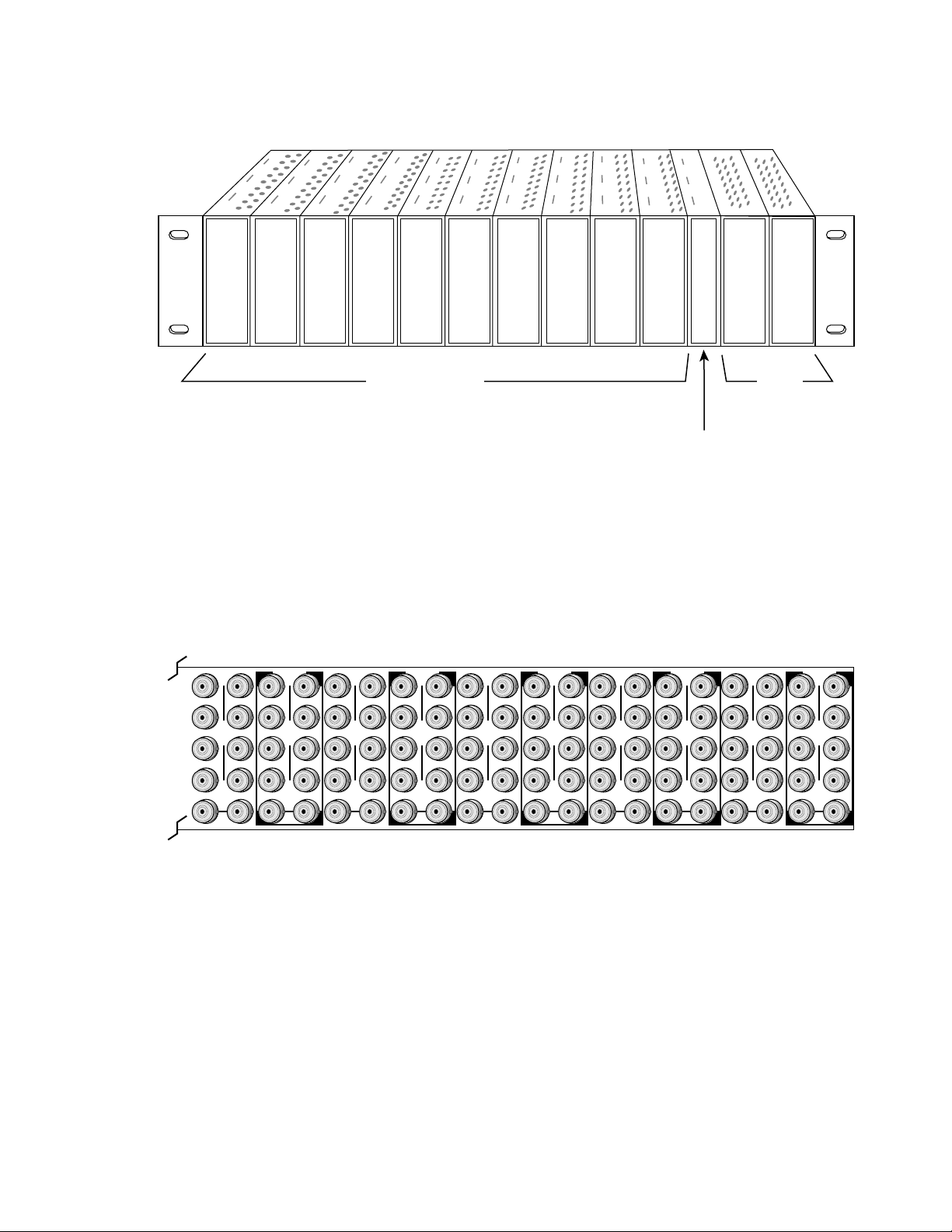
Frame Monitor Module or
Network Interface Module
Any 8900 Module
Power
Supplies
(only)
8067_04
1.
2.
3.
Figure 1. 8900 Series Frame
Installation
DA10
J1 J2
O
J3 J4
U
T
J5 J6
J7 J8
J9 J10
IN
DA9
J2
J1 J2
O
J4
J3 J4
J6
J5 J6
J8
J7 J8
J9 J10
IN
8900 modules are interchangeable within the module cells. There are 10
BNC connectors in each cell’s I/O group. The functional assignment of
each connector in a group is determined by the module that is placed in
that cell. The maximum number of modules an 8900 frame can accept is
ten. Figure 2 illustrates the rear connector plate for an 8900 Series frame.
Figure 2. 8900 Series Frame Rear Connector
DA3
J2
J1 J2
O
J4
J3 J4
U
T
J6
J5 J6
J8
J7 J8
J9 J10
IN
DA2
J1 J2
O
J3 J4
U
T
J5 J6
J7 J8
J9 J10
IN
J1 J2
J3 J4
J5 J6
J7 J8
U
T
DA8
J1 J2
O
J3 J4
U
T
J5 J6
J7 J8
J9 J10
IN
DA7
J1 J2
J2
O
J3 J4
J4
U
T
J5 J6
J6
J7 J8
J8
J9 J10
IN
DA6
J1 J2
O
J3 J4
U
T
J5 J6
J7 J8
J9 J10
IN
DA5
J1 J2
J2
O
J3 J4
J4
U
T
J5 J6
J6
J7 J8
J8
J9 J10
IN
DA4
J1 J2
O
J3 J4
U
T
J5 J6
J7 J8
J9 J10
IN
To install a module in the frame:
Insert the module, connector end first, with the component side of the
module facing to the right and the ejector tab to the top.
DA1
O
U
T
J9 J10
IN
8067-03
Verify that the module connector seats properly against the backplane.
Press the ejector tab in to seat the module in place.
8920ADT Instruction Manual 3
Page 10
8920ADT Analog Audio to AES/EBU Converter with Delay Tracking
Cabling
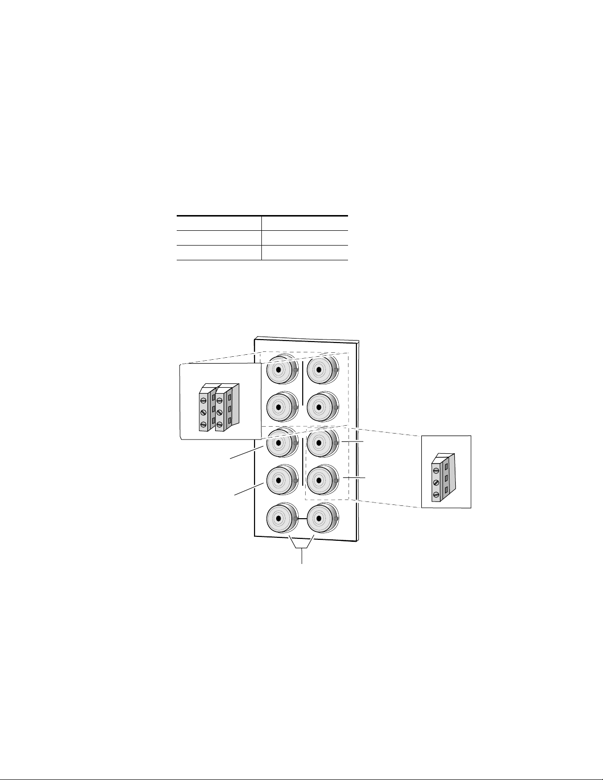
Inputs
The 8920ADT receives a pair of balanced differential analog inputs (left and
right channels) via the rear plug-in adapter connected to BNCs J1 – J4 as
shown in Figure 3. Connect a balanced input source to the stereo pair input
terminal block as specified in Table 2.
Table 2. Balanced Input Connections
Audio Channel Input Terminal Block
Left L +, GND, L –
Right R +, GND, R –
CAUTION The input signal must be balanced. Connecting an unbalanced input signal at
high signal levels may damage the input receivers.
Balanced
input adapter
L+
GND
L–
8920ADT
Grass Valley
Adapter
Figure 3.
Delay control in
Delay control out
(buffered output)
Input/Output Connectors
DAx
J1
R+
GND
R–
J3
J5
J7
J9
O
U
T
IN
Reference
loop-through input
J2
J2
J4
J4
J6
J6
J8
J8
J10
AES output (+)
AES output (-)
8067_02
Balanced
output adapter
Grass Valley
Adapter
+
GND
–
4 8920ADT Instruction Manual
Page 11

Outputs
The 8920ADT provides two unbalanced AES3id/EBU serial digital outputs
J6 (AES Output +) and J8 (AES Output –). The module can be jumpered to
use these outputs as a balanced differential AES3id output using the BNCto-terminal strip output adapter provided.
Connect balanced or unbalanced outputs as specified in Table 3.
Table 3. Output Connections
Unbalanced Outputs
Audio Channel BNC Connector Audio Channel Terminal Block
AES3id Output +
AES3id Output – J8, – OUT
Delay Control In/Out
An RS-232 level control signal from a frame synchronizer can be connected
to the Delay Control In BNC at J5 for auto-tracking audio delay. The Delay
Control In signal is also buffered and sent to the Delay Control Out BNC at
J7 so multiple units can be daisy chained to the frame synchronizer control
line.
J6, + OUT
Installation
Balanced Outputs
Single balanced output +, GND, –
Reference Inputs
Loop-through input BNCs at J9 and J10 are provided for the required
module reference. The reference signal can be an AES 48 kHz Word Clock,
video reference (NTSC/PAL color black), or an AES3id signal. If the
looping connector is not used, terminate the BNC into 75
Ω
.
8920ADT Instruction Manual 5
Page 12

8920ADT Analog Audio to AES/EBU Converter with Delay Tracking
Power Up
The front LED indicators and configuration switches are illustrated in
Figure 4. Upon power-up, the green PWR LED should light and the yellow
CONF LED should illuminate for the duration of module initialization.
Operation Indicator LEDs
With factory default configuration and valid input and reference signals
connected, the green PWR LED and the green REF LOCK LED should be
on.
Figure 4. Operation Indicator LEDs
PWR (green)
TRK ENABLE
(yellow)
TRACKING
(green)
L > -20dBFS
(green)
R > -20dBFS
(green)
FAULT (red)
COMM (yellow)
CONF (yellow)
REM OVER (yellow)
REF LOCK (green)
LEFT CLIP (red)
8067_06
RIGHT CLIP (red)
A red FAULT LED indicates an error situation and, with the other LEDs,
can indicate the operational conditions presented in Table 4. The table
describes signal output and LED indications for various input/reference
combinations and user settings.
6 8920ADT Instruction Manual
Page 13

Table 4. Indicator LEDs and Conditions Indicated
LED Indication Condition
FAULT
(red)
COMM
(yellow)
CONF
(yellow)
PWR
(green)
REM OVER
(yellow)
REF LOCK
(green)
TRK ENABLE
(yellow)
TRACKING
(green)
L >-20 DBFS
(green)
R >-20 DBFS
(green)
LEFT CLIP
(red)
RIGHT CLIP
(red)
This LED is currently not used. It will be on continuously.
Off Normal operation.
On continuously Module has detected an internal fault.
Flashing Reference input is faulty or not present.
Off No activity on frame communication bus.
Long flash Location Command received by the module from a remote control system.
Short flash Activity present on the frame communication bus.
Off Module is in normal operating mode.
On continuously
Flashing Indicates rate of change of paddle-controlled analog setting.
Off No power to module or module’s DC/DC converter failed.
On continuously Normal operation, module is powered.
Off Module configuration matches switch and jumper settings.
On continuously
Off Module does not detect a valid reference signal.
On continuously Valid reference signal is present and module is locked to it.
Off Delay tracking input not present.
On continuously Delay tracking input present.
Off Left channel level is less than -20 dBFS.
On continuously Left channel level is greater than -20 dBFS.
Flashing Left channel level is transitioning through -20 dBFS
Off Right channel level is less than -20 dBFS.
On continuously Right channel level is greater than -20 dBFS.
Flashing Right channel level is transitioning through -20 dBFS
Off Left channel digitized signal level is less than -0.5 dBFS.
On continuously Left channel digitized signal level is greater than -0.5 dBFS.
Flashing Left channel digitized signal level is transitioning through -0.5 dBFS.
Off Right channel digitized signal level is less than -0.5 dBFS.
On continuously Right channel digitized signal level is greater than -0.5 dBFS.
Flashing Right channel digitized signal level is transitioning through -0.5 dBFS.
Module is initializing, changing operating modes or updating firmware. Simultaneous CONF and FAULT LEDs on indicate FPGA load error.
Module configuration may not match switch and jumper settings. Control has been
remotely overridden.
Power Up
8920ADT Instruction Manual 7
Page 14

8920ADT Analog Audio to AES/EBU Converter with Delay Tracking
Table 5 provides the possible input conditions and the resulting output
condition.
Table 5. Possible Operating Conditions
Audio Input Condition Reference Input Condition Output Condition
Audio inputs present Valid reference input present AES/EBU serial digital output sampled at 48 kHz.
No audio input signal present Valid reference input present AES/EBU serial digital output sampled at 48 kHz. See S/N specification for level.
Audio inputs present Reference not present AES/EBU serial digital output sampled at approximately 48 kHz ±1 Hz. Internal
Audio inputs present Invalid reference input Will pull AES/EBU output toward high or low limit of lock range and could pro-
free run clock rate.
duce erratic timing shift and Channel Status Bit errors. Reference Lock LED will
be invalid and GUI tally will indicate 48 K Word Clock reference present even if a
video reference is used.
8 8920ADT Instruction Manual
Page 15

Configuration
Configuration
The 8920ADT can be configured locally using onboard switches and
jumpers or remotely using the 8900NET Network Interface module with
version 2.1 or later software.
The following parameters must be set on the 8920ADT module:
■
Input level (Left and Right) — gain adjustment of analog input levels
for full-scale digital outputs (0 dBFS),
Delay — amount of delay applied to digital output signal,
■
■
Output mode — channel swapping, summing, tone and phase inversion,
■
Output audio bit resolution — selection of 20-bit or 24-bit output,
Balanced or unbalanced outputs, and
■
■
Control mode — Local/remote or local control only (remote lockout).
Local Onboard Module Configuration
The 8920ADT module can be configured locally using the jumpers, rotary
switches and the paddle switch shown in Figure 5 on page 10. The CONF
LED indicates status of the configuration process.
These components perform the following:
SW 1 Control (rotary) switch selects functions performed by paddle
■
switch SW 3. Refer to Table 6 for details.
■
SW 2 Mode (rotary) switch selects a desired output configuration (0
through 9, A through F), although not all positions are used. Refer to
Table 7 on page 12 for details.
SW 3 (paddle) switch executes the functions selected by the Control
■
rotary switch. Refer to Table 6 for details.
■
Jumper JP4 sets control mode for Local only or Remote and Local.
Jumper JP6 sets the output bit resolution (20- or 24-bit).
■
Jumpers JP7 and JP8 determine whether AES outputs are balanced or
■
unbalanced.
■
CONF (configuring) LED – when on, indicates the module is initializing or processing configuration information.
8920ADT Instruction Manual 9
Page 16

8920ADT Analog Audio to AES/EBU Converter with Delay Tracking
Figure 5. Module Configuration Switches and LEDs
LOCAL
JP4
L & REM
CONF (yellow)
SW 2 – MODE
Rotary Switch
JP4
SW 1 – CONTROL Rotary Switch
SW 3 – Paddle Switch
Table 6 gives the functions of each selection on the Control rotary switch
(SW 1) and the action of the paddle switch (SW 3) in each function.
Remote Control Lockout
Jumper across
pins 1 – 2
1
locks out remote control
Jumper across pins 2 – 3
enables remote
and local control
JP6
Balanced/Unbalanced Outputs
Bal
JP7
3
3
JP8
Bal
pins 1 – 2
1
for unbalanced outputs
Jumpers across
1
pins 2 – 3 for
Unbal
balanced output
Jumpers across
Unbal
Jumpers across pins
5 – 6 for 20-bit output
1
6
JP6
Jumpers across pins
4 – 5 for 24-bit output
Output Audio Bit Resolution
JP7
JP8
8067_05
Table 6. Control Rotary Switch Function Selections
Control Switch Paddle Switch
Position Function Up Down
0 Disable paddle control – –
1 Level adjust for both channels
†
Increase Decrease
2 Level adjust for left channel Increase Decrease
3 Level adjust for right channel Increase Decrease
4 Delay Increase Decrease
5 – D Disable paddle control – –
E User settings Recall Save
F Factory settings Recall –
†
Any offset between the channels will be maintained in this adjustment.
10 8920ADT Instruction Manual
Page 17

Input Level Adjustments
0
1
2
3
4
5
6
7
8
9
A
B
C
D
E
F
Default
Position
The maximum signal level of the analog input must be set for full-scale
digital outputs (0 dBFS) on the left and right channels. Fine and coarse gain
controls are tied together so that the gain changes in a continuous fashion
with the paddle switch.
To adjust input levels, use the paddle switch (SW 3) on the front of the
module and set the Control rotary switch (SW 1) to the position given in
Table 6 on page 10 to adjust both channels together, or the left and right
channels individually.
Set the Mode Rotary Switch at the front of the module to the Default position marked 0 as shown at left. The Default position will put each channel
output into a normal mode with no phase inversion, channel swapping or
summing.
To correctly adjust the 8920ADT for your digital application, determine
your maximum signal level (MSL). This is the level above which digital
clipping occurs. This module has been set up at the factory with a
maximum signal level default value of +24 dBu = 0 dBFS.
Configuration
Note
The paddle switch changes input levels by increments of approximately
0.1 dB when held momentarily. Holding the switch up or down for about 1
second activates a continuous change mode that ramps the change rate from
about 0.1 dB per second to 0.6 dB per second. The yellow CONF LED will
flash slow (0.1 dB rate) or fast (0.6 dB rate) to indicate the change rate.
There are three ways to adjust the paddle switch for the proper level:
■
Apply the maximum signal level for your device to the analog input
and monitor the AES output with a meter that indicates digital level in
dBFS. Adjust the paddle switch for each channel until the meter indicates 0.0 dBFS.
Note Because the paddle switches have a resolution of 0.1 dB, you may not be able
reach 0.0 dBFS exactly. Use the closest negative setting possible.
■ Apply an input audio level that is -20 dB below the maximum level,
(+4 dBu for the default, +24 dBu -20 dB = +4 dBu) and adjust the AES
output as indicated on a digital audio meter to -20 dBFS.
Note If you have no meters calibrated in dBFS you can use the tone output position
to compare with the output level. Tone output is position E on the Function
Switch and outputs a 1 kHz tone at -20 dBFS. Note the internal tone level indication while monitoring the AES output and switch back to 0 or F position on
the Function Switch, then adjust the gain paddle switch to the same level as the
internal tone level.
8920ADT Instruction Manual 11
Page 18

8920ADT Analog Audio to AES/EBU Converter with Delay Tracking
■ Apply the maximum signal level to the input and adjust the paddle
switch for each channel until the clip LED comes on. This is -0.5 dBFS,
and by tapping the paddle switch four more times you will be within
0.15 dB (worst case) of the correct setting.
Adjusting Delay
For an AES/EBU signal the front paddle switch adds (up) or subtracts
(down) delay increments of 2 ms (1/16 video frame) each. Holding the
switch in either direction will cause the delay to step at regular intervals
until it is held for one to two seconds. After this interval, the rate of change
increases to 32 ms per step until the paddle is released or minimum or
maximum delay is reached. Both channels of audio are delayed together.
Note Delay should be set without an auto-tracking signal input.
Configuring Output Mode
The 8920ADT provides thirteen possible output configurations as shown in
Table 7. The module can be configured using the rotary switch shown in
Figure 5 on page 10. To make a configuration setting, rotate the switch to
the desired output configuration. The 16-position rotary switch selects one
of 13 possible output modes. Positions B and C are not used and positions
0 and F select the same mode, the factory default.
Table 7. 8920ADT Output Mode Configuration
Switch
Position
0 Factory default – No phase inversion, channel swapping or summing.
1 Channel swap – Left and Right.
2 Both channels phase inverted.
3 Left channel phase inverted.
4 Right channel phase inverted.
5 Right channel to both channel outputs.
6 Left channel to both channel outputs.
7 Left plus Right to both channel outputs (-6 dB mono sum).
8 Left minus Right to both channel outputs.
9 Left plus Right to Left channel output and Left minus Right to Right channel output.
A Left plus Right to both channel outputs and both channels phase inverted.
B Not used (outputs AES silence).
C Not used (outputs AES silence).
D Tone 1 to all channels (AES Silence).
E Tone 2 to all channels (1 kHz, -20 dBFS).
F Factory default – No phase inversion, channel swapping or summing.
Mode Description
12 8920ADT Instruction Manual
Page 19

Remote Control Lockout
When a jumper is placed across pins 1 and 2 of jumper block JP4 (see
Figure 5 on page 10), module output mode settings are adjustable from the
Local on-board switches only. To have both Local and Remote access, set
the jumper across pins 2 and 3.
Configuration
8920ADT Instruction Manual 13
Page 20

8920ADT Analog Audio to AES/EBU Converter with Delay Tracking
Remote Configuration and Monitoring
8920ADT configuration and monitoring can be performed remotely using
the 8900NET interface (version 2.1 or later) in 8900TF or TFN frames (see
Figure 6). This section describes the GUI access to the module configura-
tion functions. Refer to the 8900NET Network Interface Module Instruction
Manual for information on setting up and operating the 8900 frame network.
For remote access, make sure jumper block JP7 on the module is set for both
Local and Remote access (Figure 5).
Note The physical appearance of the menu displays shown in this manual repre-
sent the use of a particular platform, browser and version of 8900NET
module software. They are provided for reference only. Displays will differ
depending on the type of platform and browser you are using and the version
of the 8900NET software installed in your system.
The 8900 modules can be addressed by clicking on a specific module icon
in the frame status display or on a module name or slot number in the link
list on the left.
Figure 6. 8900NET GUI
The Links section lists the frame and its current modules. The selected link's Status
page is first displayed and the sub-list of links for the selection is opened. The sub-list
allows you to select a particular information page for the selected device.
Content display section displays the information page
for the selected frame or module (frame slot icons are also
active links).
14 8920ADT Instruction Manual
Page 21

The 8920ADT will indicate a SMPTE Alarm fault on the Frame Status
display for the following alarms:
■ Missing or unlocked input, or
■ Board failure.
Module Configuration Displays
The 8900 GUI provides the following links and displays for the 8920ADT
module (Figure 7):
■ Status and Slot Configuration displays showing status and slot config-
uration information (location and user assigned names),
■ Module Configuration displays, and
■ Software Update display.
The Status and Slot Configuration displays operate in the same manner for
all remote controllable 8900 modules. Refer to the 8900NET manual for
more information on these displays. Some functions listed may not be supported by a particular module. These will be indicated as not supported.
Configuration
Figure 7. 8920ADT Display Links
Status and Slot Configuration Displays
Module Configuration Displays
Software Update Display
Software Update Displays
The Software Update display allows you to download new software versions for the module. Refer to the 8900NET manual and the Grass Valley
Group web site at http://www.grassvalleygroup.com for complete details
and new software versions.
Module Configuration Displays
This section discusses the Module Configuration Displays used to set
parameters required for 8990ADT module operation. You may select
output mode, set signal levels, and adjust delay. Press the
activate the selections.
APPLY button to
8920ADT Instruction Manual 15
Page 22

8920ADT Analog Audio to AES/EBU Converter with Delay Tracking
Control and Status
The Control and Status display (see Figure 8) provides controls for setting
Use
This
Link
the following parameters on the 8920ADT module:
■ Operational (output) mode, and
■ Output level adjustment.
Figure 8. Control and Status Page in Slider Control Mode
16 8920ADT Instruction Manual
Page 23

Configuration
Set the Operational Mode for the desired output of the module from the
thirteen selections listed below in Table 8 and shown in the menu display
in Figure 8 on page 16. After making the selection, click the Apply button
to activate it.
Table 8. Remote Control Output Configuration Modes
Mode Name Mode Description
Default Factory default with no phase inversion, channel swapping or summing.
L/R Swap Swaps left and right channel outputs.
L/R Invert Both left and right channel outputs phase inverted.
L Invert Left channel output phase inverted.
R Invert Right channel output phase inverted.
R Mono (R to L/R) Right channel to both channel outputs.
L Mono (L to L/R) Left channel to both channel outputs.
L plus R to L/R Left plus right to both channel outputs.
L minus R to L/R Left minus right to both channel outputs
L plus R, L minus R Left plus right to left channel output and left minus right to right channel output.
(L plus R) Inv to L/R Left plus right to both channel outputs with both channel outputs phase inverted.
AES Silence AES silence on both left and right channel outputs.
1K@ -20dBFS Tone to both channel outputs.
Gain adjustment of the module output levels can be done from this display.
Adjust the gain in either Sliders mode or Numeric mode (shown in Figure 9
on page 18). The single arrows buttons increment or decrement the value
by 0.1 dB. The double arrow buttons will increment or decrement the value
by approximately 1.0 dB. These controls will allow you 0.0 to 20 dB range
of adjustment.
Note In Numeric mode only, values selected with the single or double arrow keys
will be enabled immediately. All other display entries, including typed in
values, require pressing Apply before the selection is enabled.
8920ADT Instruction Manual 17
Page 24

8920ADT Analog Audio to AES/EBU Converter with Delay Tracking
Figure 9. Numeric Control Mode for Level Adjustment
Numeric Entry Mode
The following status items will be reported in this display (see Figure 8 on
page 16):
■ Model name — as defined on the main Status page.
■ Frame location — indicates the frame name and slot number.
■ Left and Right Ch > -20 dBFS — indicates whether the left and right
channel digital output levels are greater than -20 dBFS (True) or less
than -20 dBFS (False).
■ Left and Right Ch > -0.5 dBFS Clip — indicates whether the digital
output clipping levels are greater than -0.5 dBFS (True) or less than -0.5
dBFS (False).
■ Reference Signal — indicates one of these reference signal input condi-
tions:
■ No reference signal present,
■ AES signal present,
■ 525 video signal present,
■ 625 video signal present, or
■ 48 kHz Word Clock signal present.
■ Output Audio Bit Res. — 20-bit or 24-bit digital output (Jumper selec-
tion, see Figure 5 on page 10).
18 8920ADT Instruction Manual
Page 25

Configuration
Audio Delay
The Audio Delay display (see Figure 10) provides controls for setting the:
Use
This
Link
■ Control mode of the display (Slider or Numeric, and
■ Fixed Delay provided by the module.
If Auto Tracking is active, the delay provided by the 8900 Frame Sync
module will be added to the module’s fixed delay. The display tallies
amounts for Auto Tracking, fixed Delay Adjust, and the resulting Total
Delay.
Figure 10. 8920ADT Audio Delay Display, Slider Mode
Slider bars indicate
setting relative to the
maximum 1365 ms
total delay maximum
The slider mode provides a view of the delay setting relative to the
module’s maximum 1365 ms.
In numeric mode (see Figure 11 on page 20), the display provides delay
amounts in millisecond units. When using the increment/decrement
buttons the change is immediately applied. When numeric values are
entered in the window, it is necessary to click on the
Apply button.
8920ADT Instruction Manual 19
Page 26

8920ADT Analog Audio to AES/EBU Converter with Delay Tracking
Figure 11. 8920ADT Audio Delay Display, Numeric Mode
In numeric mode, buttons
make changes automatically
(Apply button not required)
>> = 20 ms increments
> = 2 ms increments
20 8920ADT Instruction Manual
Page 27

Use
This
Link
Configuration
User Settings
The User Settings menu allows you select the following parameters shown
in Figure 12:
■ Get Factory Defaults for:
■ Audio gain (left and right) — 4 dB,
■ Delay — 0.0,
■ Monitor Audio Inputs — Disabled, and
■ Control Action — Independent.
■ Save/Recall User Settings including:
■ Audio gain (left and right), and
■ Delay.
■ Enable/disable Monitor Audio Inputs.
When enabled, the module Status page will indicate if input signals are
present and provide a warning when they are not detected. When disabled the Status page shows a gray input signal arrow indicating the
input status is not monitored.
Note Operation Mode is not saved or recalled as factory default or user settings.
Operation Mode must always be changed using the on-board rotary switch
or the Control and Status page.
Figure 12. 8920ADT User Settings Display
8920ADT Instruction Manual 21
Page 28

8920ADT Analog Audio to AES/EBU Converter with Delay Tracking
Specifications
Table 9. 8920ADT Specifications
Parameter Value
Analog Input
Number of inputs 2
Level for full-scale output +8 dBu to +28 dBu
Connector type Plug-in terminal block on adapter
Input impedance > 22 kΩ
Common mode input voltage ±10 V maximum
Differential DC ±0.25 V maximum
Common mode rejection > 90 dB, 50/60 Hz, > 45 dB to 20 kHz
AES Reference Input
Number of inputs 1 Loop-through
Signal type AES3id – 1992, word clock (48 kHz sample rate), video (PAL/NTSC)
Connector type 75 Ω BNC
Common mode range ±1 V
Differential voltage range 200 mV to 12 V p-p
Input return loss > 15 dB 100 kHz – 10 MHz @ 75 Ω
Sample rate 48 kHz
Maximum jitter < 6.5 ns RMS
AES/EBU Outputs
Number of outputs 2 unbalanced 75 Ω or 1 balanced 110 Ω with terminal adapter
Connector type 75 Ω BNC or 110 Ω terminal adapter
Signal type SMPTE 276M (AES3id – 1992) unbalanced or
Output level Unbalanced 1 V ± 0.1 V p-p terminated into 75 Ω or
Rise/fall time 30 ns to 44 ns across 75 Ω load (AES-3id) or
Sample rate 48 kHz
Output return loss > 15 dB (100 kHz to 6 MHz)
Maximum jitter < 6.5 ns RMS
Channel status bits set 20-bit: Byte 0 = 85 hex, Byte 23 = 71 hex
Output bit resolution 20 or 24-bit jumper selectable
Performance (@ +28 dBU input and full scale output)
Module insertion to operation < 1.5 seconds
Signal-to-noise ratio >102 dB, 20 Hz to 20 kHz
THD+Noise, swept 20 Hz to 20 kHz < 0.005%, 20 Hz to 20 kHz, + 24 dBu input
Interchannel crosstalk < -95 dB, 20 Hz - 20 kHz, +28 dBu input
Intermodulation distortion < -100 dB CCIF two-tone test, 19 kHz and 20 kHz tones
Frequency response ± 0.05 relative to 1 kHz, 20 Hz to 20 kHz
AES3-1992 balanced transformer output
Balanced 2 V to 7 V p-p terminated into 110 Ω
5 ns to 30 ns across 110 Ω load (AES3)
24-bit: Byte 0 = 85 hex, Byte 2 = 04 hex, Byte 23 = 1E hex
>105 dB “A” weighted
22 8920ADT Instruction Manual
Page 29

Specifications
Table 9. 8920ADT Specifications - (continued)
Parameter Value
DC offset < ± 1 mV
Electrical length (input to output delay) 940 µs minimum, 1,365 ms maximum
Environmental
Frame temperature range 0 to 45 degrees C
Operating humidity range 0 to 90% non-condensing
Non-operating temperature -10 to 70 degrees C
Static withstand 5 kV (330 Ω, 150 pF) any input or output
Factory calibration Calibrated for +24 dBu set to 0 dBFS (mode switch at 0)
Mechanical
Frame type 8900 Series
Power Requirements
Supply voltage ±12 V
Power consumption < 2 Watts
8920ADT Instruction Manual 23
Page 30

8920ADT Analog Audio to AES/EBU Converter with Delay Tracking
Service
The 8920ADT modules make extensive use of surface-mount technology
and programmed parts to achieve compact size and adherence to
demanding technical specifications. Circuit modules should not be serviced in the field unless you are directed to do so by Customer Service.
If your module is not operating correctly, proceed as follows:
■ Check frame and module power and signal present LEDs.
■ Check for presence and quality of input signals.
■ Verify that source equipment is operating correctly.
■ Check cable connections.
■ Check output connections for correct I/O mapping (correct input con-
nector is used for the corresponding channel output).
Refer to Figure 4 for the location of PWR LED and Table 4 on page 7 for
proper LED indications.
If the module is still not operating correctly, replace it with a known good
spare and return the faulty module to a designated Grass Valley repair
depot. Call your Grass Valley representative for depot location.
Refer to the Contacting Grass Valley Group at the front of this document for
the Grass Valley Customer Support Information number.
24 8920ADT Instruction Manual
Page 31

Functional Description
Figure 13. The 8920ADT converts two channels of analog audio into one 48
kHz sample-rate serial data stream, which is then delayed and converted
into an AES/EBU formatted output signal. Refer to the block diagram in
Figure 14 while reading the following functional description.
Figure 14. 8920ADT Block Diagram
Adj Gain
Stage
Left
Audio
Input
Right
Audio
Input
Pre A/D Gain Control
2-Channel
A/D
Serial Audio Data
Functional Description
Power
Supply
+/- 12V
Video/AES3id
AES Word Clock
Reference
Loop-through
Ref
Input
Delay Control I/F
RS232
Buffered
RS232 Out
VCXO
Mode, Control,
Gain/Delay
Front Controls
To 8900NET
Module
Loop Filter
Sync Separator
Word Clock
Receiver
Controller
Fault, Comm, Conf,
Pwr, Rem Ovr
LEDs
Odd/Even
48 Hz/AES
Phase
Detector
H/V Sync
FPGA
Routing and Control
Processor
Tracking, Ref Locked,
Left/Right Clip,
Left/Right >-20dBFS
LEDs
Phase
Detector
AES/EBU Serial Data
Loop Filter
Control
Address
Data
VCXO
2 AES3id
Outputs or
1 AES3
Balanced
Output
Line
Drivers
Audio
Delay
Memory
8067_01
8920ADT Instruction Manual 25
Page 32

8920ADT Analog Audio to AES/EBU Converter with Delay Tracking
Differential Input, Analog Gain and A/D Converters
The analog input is applied to a differential amplifier stage. This converts
the signal to single-ended and applies it to the coarse gain stage. Coarse
gain control pre-conditions the incoming signal before it is applied to the
A/D converters.
The fine gain control is by two center-off toggle switches on the front of the
module. They provide a 2 dB range of fine gain adjustment in approximately 0.1 dB increments. The control takes approximately 6 to 10 seconds
to transition from minimum to maximum.
The signal is converted back to a differential signal and applied to the 24bit A/D converter, then to the Routing and Control FPGA (Field Programmable Gate Array).
Digital Reference Input
The digital reference is applied via the loop-through input to the AES
receiver and phase-locked loop. This provides clock and data to the Control
and Routing FPGA and the A/D converters.
Routing and Control FPGA
The signals from the A/D converters are applied to the Routing and
Control FPGA. The incoming signal processing and level is determined by
the setting of one of 16 possible mode commands from a four-bit rotary
encoder switch and four signals from the level toggle switches. After processing and delaying, the signals are embedded into an AES stream and
applied to the Output Drivers.
The Routing and Control section also drives the front panel LEDs and interfaces to the Controller section.
Controller
The Controller interfaces with the Routing and Control FPGA, the
EEPROM and the 8900 Frame Bus. The Controller also provides the FPGA
code that is downloaded to the FPGA during boot-up.
The Controller section handles local control and monitoring, as well as
remote control and monitoring via the frame bus (when an 8900NET
module is installed in the frame). Module settings are stored in the
EEPROM for power up recall.
26 8920ADT Instruction Manual
Page 33

Power Supply
Functional Description
Power is fed from ±12 V rails of the frame’s switching power supply. Each
stage of the module receives it’s own, separate, highly regulated and filtered power source. Two-stage regulation is used in the analog section of
the ADC to reduce switching noise.
8920ADT Instruction Manual 27
Page 34

8920ADT Analog Audio to AES/EBU Converter with Delay Tracking
28 8920ADT Instruction Manual
Page 35

Index
Numerics
8920ADT
functional description
25
A
auto-tracking 19
B
balanced output 5
C
cabling 4
input 4
output 5
COMM LED 7
CONF (configuring) LED 7, 9
configuration 12
jumpers 9
LEDs 9
local on-board 9
remote 14
switches 9
connectors 3
input/output 4
output 5
control 16
control rotary switch 10
D
F
factory defaults 21
Fault LED 6, 7
fault report 15
fixed delay 19
frame
cell locations
cooling capacity 2
module capacity 2
power capacity 2
frame status display 14
frame sync 19
function rotary switch 9
2
G
gain adjustment
local
11
GUI 14, 15
I
indicator LEDs 6
input
level adjustments
loopthrough 4
specification 22
input/output conditions 8
inputs
reference
installation 2
5
11
delay 12, 19
delay units 19
8920ADT Instruction Manual Index-1
L
LEFT IN > -20 dBFS LED 7
LEFT IN CLIP LED 7
level indication 18
LOCK LED 7
Page 36

loop-through input 5
M
maximum signal level 11
mode
output
module
block diagram
cells 3
install 3
placement 2
replacement 24
monitor audio inputs 21
12, 16
25
REF LOCK LED 6
reference inputs 5
reference signal 5
REM OVER (remote override) LED 7
remote control displays
User Settings
remote control lockout 13
jumper 9, 13
RIGHT IN > -20 dBFS LED 7
RIGHT IN CLIP LED 7
rotary switch 9, 12
output mode 12
21
S
N
network 14
O
operational conditions
LED indications
operational mode 16
output 5
configuration 12
jumpers 5
level 16
mode 12
operation modes 21
remote level adjustment 17
specification 22
terminal 4
output/input conditions 8
7
P
save/recall 21
setting delay 12
SMPTE alarm 15
specifications 22
status 16
status indications 18
T
termination 4
total delay 19
troubleshooting 24
U
unbalanced output 5
user settings 21
paddle switch 9
paddle switches
description
power requirements 23
PWR LED 6, 7
11
R
recall/save 21
Index-2 8920ADT Instruction Manual
 Loading...