

Page 1
8920ADC
AUDIO A-TO-D CONVERTER
Instruction Manual
SOFTWARE VERSION 2.0.1A
071059503
JUNE 2005
Page 2

Contacting Grass Valley
Region Voice Fax Address Web Site
North America (800) 547-8949
Support: 530-478-4148
Pacific Operations +852-2585-6688
Support: 852-2585-6579
U.K., Asia, Middle East +44 1753 218 777 +44 1753 218 757
France +33 1 45 29 73 00
Germany, Europe +49 6150 104 782 +49 6150 104 223
Copyright © Thomson Broadcast and Media Solutions All rights reserved.
Grass Valley Web Site
Sales: (530) 478-3347
Support: (530) 478-3181
+852-2802-2996
Grass Valley
P.O. Box 599000
Nevada City, CA 959597900 USA
www.thomsongrassvalley.com
The www
Online User Documentation
.thomsongrassvalley.com web site offers the following:
— Current versions of product catalogs, brochures,
data sheets, ordering guides, planning guides, manuals, and release notes
in .pdf format can be downloaded.
FAQ Database
— Solutions to problems and troubleshooting efforts can be
found by searching our Frequently Asked Questions (FAQ) database.
Software Downloads
— Software updates, drivers, and patches can be down-
loaded.
2 8920ADC Instruction Manual
Page 3

Contents
Preface
. . . . . . . . . . . . . . . . . . . . . . . . . . . . . . . . . . . . . . . . . . . . . . . . . . . . . . . . . . . . . . . . . . . . . 5
About This Manual . . . . . . . . . . . . . . . . . . . . . . . . . . . . . . . . . . . . . . . . . . . . . . . . . . . . . 5
8920ADC Analog Audio to AES/EBU Converter
Introduction . . . . . . . . . . . . . . . . . . . . . . . . . . . . . . . . . . . . . . . . . . . . . . . . . . . . . . . . . . . 7
Installation . . . . . . . . . . . . . . . . . . . . . . . . . . . . . . . . . . . . . . . . . . . . . . . . . . . . . . . . . . . . 8
Frame Capacity . . . . . . . . . . . . . . . . . . . . . . . . . . . . . . . . . . . . . . . . . . . . . . . . . . . . . . 8
Module Placement in the 8900 Frame. . . . . . . . . . . . . . . . . . . . . . . . . . . . . . . . . . . . 8
Cabling . . . . . . . . . . . . . . . . . . . . . . . . . . . . . . . . . . . . . . . . . . . . . . . . . . . . . . . . . . . . 10
Input. . . . . . . . . . . . . . . . . . . . . . . . . . . . . . . . . . . . . . . . . . . . . . . . . . . . . . . . . . . . . 10
Outputs . . . . . . . . . . . . . . . . . . . . . . . . . . . . . . . . . . . . . . . . . . . . . . . . . . . . . . . . . . 10
Reference Inputs. . . . . . . . . . . . . . . . . . . . . . . . . . . . . . . . . . . . . . . . . . . . . . . . . . . 10
Power Up . . . . . . . . . . . . . . . . . . . . . . . . . . . . . . . . . . . . . . . . . . . . . . . . . . . . . . . . . . . . 11
Operation Indicator LEDs . . . . . . . . . . . . . . . . . . . . . . . . . . . . . . . . . . . . . . . . . . . . 11
Configuration. . . . . . . . . . . . . . . . . . . . . . . . . . . . . . . . . . . . . . . . . . . . . . . . . . . . . . . . . 13
Configuration Summary. . . . . . . . . . . . . . . . . . . . . . . . . . . . . . . . . . . . . . . . . . . . . . 13
Output Level Adjustment. . . . . . . . . . . . . . . . . . . . . . . . . . . . . . . . . . . . . . . . . . . 14
Configuring Output Mode . . . . . . . . . . . . . . . . . . . . . . . . . . . . . . . . . . . . . . . . . . 16
Remote Control Lockout. . . . . . . . . . . . . . . . . . . . . . . . . . . . . . . . . . . . . . . . . . . . 16
Local Onboard Module Configuration. . . . . . . . . . . . . . . . . . . . . . . . . . . . . . . . . . 18
Remote Configuration and Monitoring . . . . . . . . . . . . . . . . . . . . . . . . . . . . . . . . . 19
8900NET Module Information . . . . . . . . . . . . . . . . . . . . . . . . . . . . . . . . . . . . . . . 19
Newton Control Panel Configuration. . . . . . . . . . . . . . . . . . . . . . . . . . . . . . . . . 19
Web Browser Interface . . . . . . . . . . . . . . . . . . . . . . . . . . . . . . . . . . . . . . . . . . . . . 20
8920DAC Links and Web Pages . . . . . . . . . . . . . . . . . . . . . . . . . . . . . . . . . . . . . 22
User Settings Web Page . . . . . . . . . . . . . . . . . . . . . . . . . . . . . . . . . . . . . . . . . . . . 26
Slot Config Web Page . . . . . . . . . . . . . . . . . . . . . . . . . . . . . . . . . . . . . . . . . . . . . . 27
Software Update Web Page . . . . . . . . . . . . . . . . . . . . . . . . . . . . . . . . . . . . . . . . . 29
Specifications . . . . . . . . . . . . . . . . . . . . . . . . . . . . . . . . . . . . . . . . . . . . . . . . . . . . . . . . . 30
Service. . . . . . . . . . . . . . . . . . . . . . . . . . . . . . . . . . . . . . . . . . . . . . . . . . . . . . . . . . . . . . . 31
Status Monitoring . . . . . . . . . . . . . . . . . . . . . . . . . . . . . . . . . . . . . . . . . . . . . . . . . . . . . 32
LEDs . . . . . . . . . . . . . . . . . . . . . . . . . . . . . . . . . . . . . . . . . . . . . . . . . . . . . . . . . . . . . . 32
Frame Alarm . . . . . . . . . . . . . . . . . . . . . . . . . . . . . . . . . . . . . . . . . . . . . . . . . . . . . . . 33
Web Browser Interface . . . . . . . . . . . . . . . . . . . . . . . . . . . . . . . . . . . . . . . . . . . . . . . 33
SNMP Reporting . . . . . . . . . . . . . . . . . . . . . . . . . . . . . . . . . . . . . . . . . . . . . . . . . . 34
Functional Description . . . . . . . . . . . . . . . . . . . . . . . . . . . . . . . . . . . . . . . . . . . . . . . . . 35
Differential Input, Analog Gain and A/D Converters . . . . . . . . . . . . . . . . . . . . 35
Digital Reference Input. . . . . . . . . . . . . . . . . . . . . . . . . . . . . . . . . . . . . . . . . . . . . . . 36
Routing and Control FPGA . . . . . . . . . . . . . . . . . . . . . . . . . . . . . . . . . . . . . . . . . . . 36
Controller . . . . . . . . . . . . . . . . . . . . . . . . . . . . . . . . . . . . . . . . . . . . . . . . . . . . . . . . . . 36
Power Supply. . . . . . . . . . . . . . . . . . . . . . . . . . . . . . . . . . . . . . . . . . . . . . . . . . . . . . . 36
Index
8920ADC Instruction Manual 3
. . . . . . . . . . . . . . . . . . . . . . . . . . . . . . . . . . . . . . . . . . . . . . . . . . . . . . . . . . . . . . . . . . . . . . 37
Page 4

Contents
4 8920ADC Instruction Manual
Page 5

Preface
About This Manual
This manual describes the features of a specific module of the Gecko 8900
Signal Processing System. As part of this module family, it is subject to
Safety and Regulatory Compliance described in the Gecko 8900 Series
frame and power supply documentation (see the 8900TX/8900TF/8900TFN
Frames Instruction Manual
).
8920ADC Instruction Manual 5
Page 6

Preface
6 8920ADC Instruction Manual
Page 7

8920ADC Analog Audio to AES/EBU Converter
Introduction
The 8920ADC converts analog audio to digital audio. The right and left
channel audio inputs enter via a terminal block-to-BNC adapter on the rear
panel. A 48 kHz AES/EBU reference is required to lock the module, which
is connected to the loop through input BNCs. The module outputs 4
AES/EBU 75
Ω signals through BNCs on the rear panel.
The 8920ADC can modify the outgoing signal to provide channel swapping, channel summing, tone and phase inversion. The remote control
capability supports mode selection and input gain control.
The 8920ADC features:
• 24-bit resolution,
•AES/EBU loop-through reference input,
• 48 kHz sampling rate,
•Terminal block input via adapter,
• Independent input level control from +12 dBu to +28 dBu,
• 8900 Series Frame compatibility,
•Remote control via ethernet frame I/F,
•Newton Control Panel,
•SNMP monitoring, and
•Remote control lockout via onboard jumper.
8920ADC Instruction Manual 7
Page 8

Installation
Installation
Frame Capacity
1.
2.
3.
Installation of the 8920ADC module is a process of:
Placing the module in the desired frame slot,
Cabling and terminating signal ports, and
Configuring the module.
The 8920ADC module can be plugged in and removed from an 8900 Series
frame with power on. When power is applied to the module, LED indicators reflect the initialization process (see Power Up on page 11).
The 8920ADC module can be installed in all 8900 Series frames but with
varying maximum quantities determined by frame cooling capacity.
Table 1 provides the power capacity, cooling capacity, and maximum
module count for each frame type.
Table 1. Power, Cooling, and Module Capacity of 8900 Frames
Capacity Calculated
Power (W) 100 100 100
Recommended Module Cooling (W) 30 90 90
8920ADC Modules 7 10 10
Note
Module capacity figures assume no other modules are in the frame.
8900TX
Frame
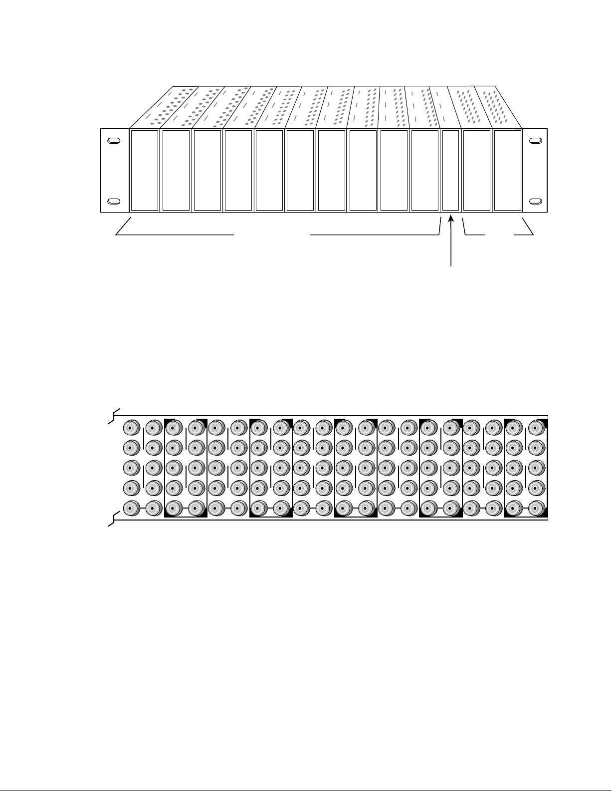
Module Placement in the 8900 Frame
There are ten cell locations in the frame to accommodate either analog or
digital modules. These are the left ten locations. Refer to Figure 1 on page 9.
The two cells on the right are allocated for the power supplies. For additional information concerning the Power Supply module, refer to the
8900 Frame Instruction Manual
The third cell from the right is allocated for the Frame Monitor or 8900NET
Network Interface controller modules. These modules provide health monitoring and control options.
.
8900TF
Frame
8900TFN
Frame
Gecko
8 8920ADC Instruction Manual
Page 9
Frame Monitor Module or
Network Interface Module
Any 8900 Module
Power
Supplies
(only)
0595-04r1
0595-03
J1 J2
J3 J4
J5 J6
J7 J8
J9 J10
IN
DA1
J2
J4
J6
J8
J1 J2
J3 J4
J5 J6
J7 J8
J9 J10
IN
DA3
J1 J2
J3 J4
J5 J6
J7 J8
J9 J10
IN
DA5
J1 J2
J3 J4
J5 J6
J7 J8
J9 J10
IN
DA2
J1 J2
J3 J4
J5 J6
J7 J8
J9 J10
IN
DA7
J1 J2
J3 J4
J5 J6
J7 J8
J9 J10
IN
DA9
J1 J2
J3 J4
J5 J6
J7 J8
J9 J10
IN
DA4
J2
J4
J6
J8
J1 J2
J3 J4
J5 J6
J7 J8
J9 J10
IN
DA6
J2
J4
J6
J8
J1 J2
J3 J4
J5 J6
J7 J8
J9 J10
IN
DA8
J2
J4
J6
J8
J1 J2
J3 J4
J5 J6
J7 J8
J9 J10
IN
DA10
O
U
T
O
U
T
O
U
T
O
U
T
O
U
T
O
U
T
O
U
T
O
U
T
O
U
T
O
U
T
1.
2.
3.
Figure 1. 8900 Series Frame
Installation
8900 modules are interchangeable within the module cells. There are 10
BNC connectors in each cell’s I/O group. The functional assignment of
each connector in a group is determined by the module that is placed in
that cell. The maximum number of modules an 8900 frame can accept is ten.
Figure 2 illustrates the rear connector plate for an 8900 Series frame.
Figure 2. 8900 Series Frame Rear Connector
To install a module in the frame:
Insert the module, connector end first, with the component side of the
module facing to the right and the ejector tab to the top.
Verify that the module connector seats properly against the backplane.
Press the ejector tab in to seat the module in place.
8920ADC Instruction Manual 9
Page 10
Installation
Cabling
Input
Note
At the back of this manual are overlay cards that can be placed over the rear
connector BNCs to identify the specific 8920ADC connector functions.
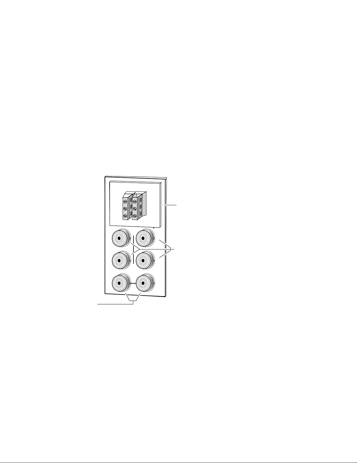
Connect a balanced input source to the stereo pair input terminal block (see
Figure 3).
CAUTION The input signal must be balanced. Connecting an un-balanced input signal
at high signal levels may damage the input receivers.
The 8920ADC can produce a full-scale output from an analog audio input
signal level of +12 dBu to +28 dBu.
Figure 3. 8920ADC Input/Output Connectors
Grass Valley
DAx
Adaptor
R+
J2
J2
GND
R–
J4
J4
T
J4
Analog balanced
input adapter
J1
J1
J3
L+
GND
L–
O
U
AES reference
loop-through input
Outputs
Reference Inputs
J5
J7
J9 J10
IN
J6
J8
J6
J8
AES outputs
0595-02
The 8920ADC has four AES/EBU serial digital outputs—J5 through J8. The
Ω
destination equipment should have a 75
through inputs that are terminated into 75
input impedance or loop
Ω .
Loop-through input BNCs are provided for the required 48 kHz AES/EBU
reference signals. Terminate the looping BNC into 75
Ω if not used.
10 8920ADC Instruction Manual
Page 11
Power Up
Operation Indicator LEDs
Power Up
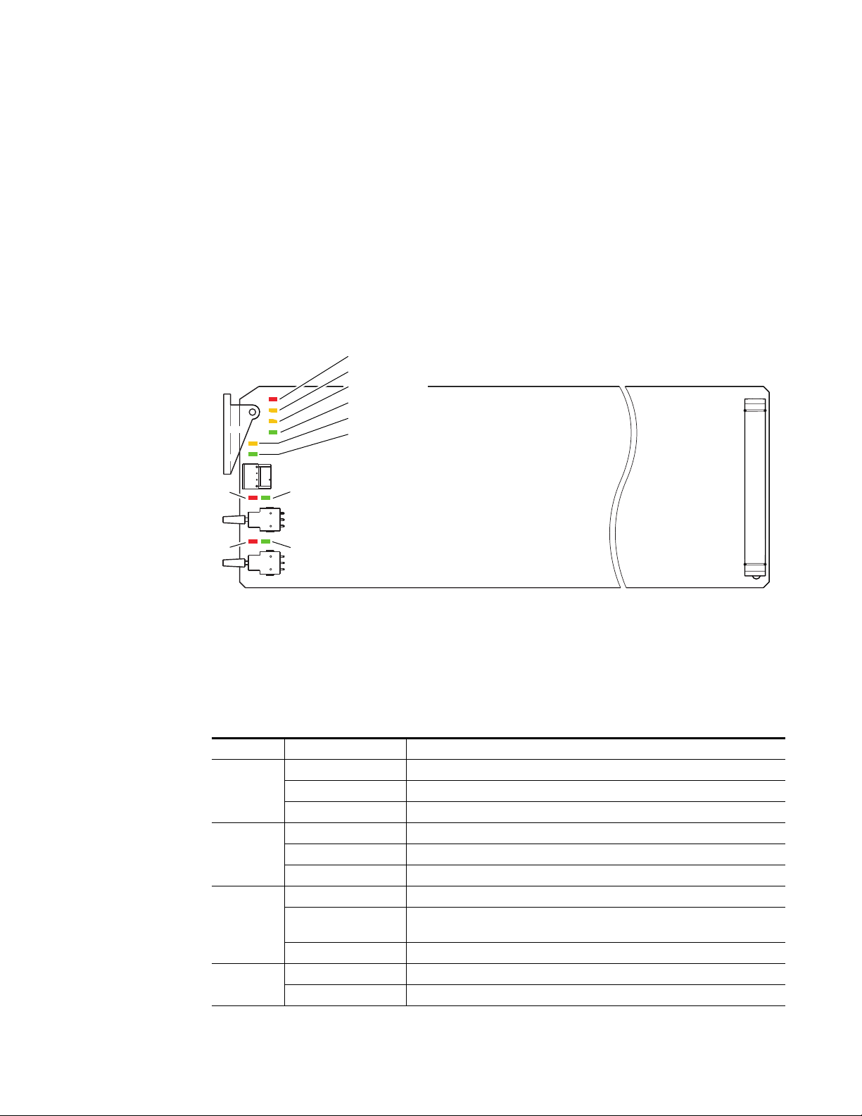
The front LED indicators and configuration switches are illustrated in
Figure 4. Upon power-up, the green PWR LED should light and the yellow
CONF LED should illuminate for the duration of module initialization.
With factory default configuration and valid input and reference signals
connected, the green PWR LED and the green LOCK LED should be on.
Figure 4. Operation Indicator LEDs
FAULT (red)
COMM (yellow)
CONF (yellow)
PWR (green)
REM OVER (yellow)
LOCK (green)
Left In
Clip (red)
Right In
Clip (red)
Left In > -20dBFS (green)
Right In > -20dBFS (green)
A red FAULT LED indicates an error situation and, with the other LEDs,
can indicate the operational conditions presented in Table 2. The table
describes signal output and LED indications for various input/reference
combinations and user settings.
Table 2. Indicator LEDs and Conditions Indicated
LED Indication Condition
FAULT
(red)
COMM
(yellow)
CONF
(yellow)
PWR
(green)
Off Normal operation.
On continuously Module has detected an internal fault.
Flashing Reference input is faulty or not present.
Off No activity on frame communication bus.
Long flash Location Command received by the module from a remote control system.
Short flash Activity present on the frame communication bus.
Off Module is in normal operating mode.
On continuously
Flashing Indicates rate of change of paddle-controlled analog setting.
Off No power to module or module’s DC/DC converter failed.
On continuously Normal operation, module is powered.
Module is initializing, changing operating modes or updating firmware. Simultaneous CONF and FAULT LEDs on indicate FPGA load error.
0595_06
8920ADC Instruction Manual 11
Page 12
Power Up
Table 2. Indicator LEDs and Conditions Indicated - (continued)
LED Indication Condition
REM OVER
(yellow)
LOCK
(green)
LEFT IN
(green)
RIGHT IN
(green)
LEFT IN
CLIP
(red)
RIGHT IN
CLIP
(red)
Off Module configuration matches switch and jumper settings.
On continuously
Off Module does not detect a valid AES in reference signal.
On continuously Valid AES in reference signal is present and module is locked to it.
Off Left channel level is less than -20 dBFS.
On continuously Left channel level is greater than -20 dBFS.
Flashing Left channel level is transitioning through -20 dBFS
Off Right channel level is less than -20 dBFS.
On continuously Right channel level is greater than -20 dBFS.
Flashing Right channel level is transitioning through -20 dBFS
Off Left channel digitized signal level is less than -0.5 dBFS.
On continuously Left channel digitized signal level is greater than -0.5 dBFS.
Flashing Left channel digitized signal level is transitioning through -0.5 dBFS.
Off Right channel digitized signal level is less than -0.5 dBFS.
On continuously Right channel digitized signal level is greater than -0.5 dBFS.
Flashing Right channel digitized signal level is transitioning through -0.5 dBFS.
Module configuration may not match switch and jumper settings. Control has been
remotely overridden.
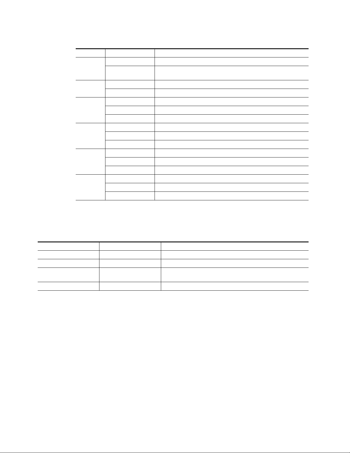
Table 3 provides the possible input conditions and the output condition
that results.
Table 3. Possible Operating Conditions
Audio Input Condition Reference Input Condition Output Condition
Audio inputs present Valid reference input present AES/EBU serial digital output sampled at 48 kHz.
No audio input signal present Valid reference input present AES/EBU serial digital output sampled at 48 kHz. See S/N specification for level.
Audio inputs present Reference not present AES/EBU serial digital output sampled at approximately 47.992 kHz. Internal
freerun clock rate.
Audio inputs present Invalid reference input Invalid AES/EBU serial digital output.
12 8920ADC Instruction Manual
Page 13

Configuration
Configuration
The 8920ADC can be configured locally using onboard switches or
remotely using the 8900NET network interface GUI or a networked
Newton Control Panel.
Refer to the following sections for configuration instructions:
•Configuration Summary (page 13)
• Local Onboard Module Configuration (page 18)
•Remote Control and Monitoring (page 19)
Operation of these control types is explained in detail in their respective
sections of this manual.
Configuration Summary
This section provides a summary of all parameters that can be configured
on the 8920DAC module. Table 6 on page 17 provides a summary in table
format of all parameters and their ranges, default values, and remote, local,
and control panel function names and locations for setting each value.
The following parameters must be set on the 8920ADC module:
•Output level (Left and Right) – coarse and fine adjustment of analog
input levels for full scale digital outputs,
•Output mode – such as channel swapping, summing, tone and phase
inversion, and
8920ADC Instruction Manual 13
Page 14

Configuration
0
1
2
3
4
5
6
7
8
9
A
B
C
D
E
F
Default
Position
Output Level Adjustment
To correctly adjust the 8920ADC for your digital application, determine
your maximum operating level and set the Coarse Level gain jumpers on
the module circuit board as described below. This is the level above which
digital clipping occurs.
Example Maximum Operating Level Setting
A setting of +24 dBu is a common maximum level. Using +24 dBu as the
maximum level, refer to Table 4 to select the lowest input level range that
includes the maximum level of +24 dBu. Select the Coarse Level Setting pin
4 to 5 jumper setting (refer to Figure 5 on page 18) because it is the highest
level supported by that range and requires the least amount of gain to bring
+24 dBu up to 0.0 dBFS level. This will give the best signal-to-noise ratio
that the system can deliver.
1.
2.
Setting Maximum Operating Level
Once you have determined the proper coarse level jumper setting, perform
the following steps:
Set the Function Rotary Switch (SW1) on the front of the module circuit
board to the position marked 0 as shown at left.
Remove the module from the frame and set jumpers on JP5 and JP6 to
the jumper setting that you determine using Table 4.
Table 4. Jumper Coarse Level Settings for 0.0 dBFS Output
Input Level JP5/JP6 Jumper Position
12 to 16 dBu Pins 1 and 2
16 to 19 dBu Pins 2 and 3
19 to 25 dBu Pins 4 and 5
25 to 28 dBu Pins 5 and 6
Return the module to the frame.
3.
Using Level Gain Toggle Switches
Note
14 8920ADC Instruction Manual
The toggle switches change input levels by increments of approximately
0.1 dB when held momentarily. Holding the switch up or down for about 1
second activates a continuous change mode that ramps the change rate from
about 0.1 dB per second to 0.6 dB per second. The yellow CONF LED will
flash slow (0.1 dB rate) or fast (0.6 dB rate) to indicate the change rate.
Page 15

Configuration
There are three ways to adjust the onboard gain toggle switches to the
proper level:
•Apply the maximum level to the input (example +24 dBu) and monitor
the AES output with a meter that indicates digital level in dBFS and
adjust the toggle switch for each channel until the meter indicates
0.0 dBFS.
Because the toggle switches have a resolution of 0.1 dB, you may not be
able reach 0.0 dBFS exactly. Use the closest negative setting possible.
•Apply an audio level that is -20 dB below the maximum level, (+4 dBu
for the example, +24 dBu -20 dB = +4 dBu) and adjust the AES output
as indicated on a digital audio meter to -20 dBFS.
If you have no meters calibrated in dBFS you can use the tone output
position to compare with the output level. Tone output is position E on
the Function Switch and outputs a 1 kHz tone at -20 dBFS. Note the
internal tone level indication while monitoring the AES output and
switch back to 0 or F position on the Function Switch, then adjust the
gain toggle switch to the same level as the internal tone level.
•Apply the maximum level to the input (example +24 dBu) and adjust
the gain toggle switch for each channel until the clip LED comes on.
This is -0.5 dBFS, and by tapping the toggle switch four more times you
will be within 0.15 dB (worst case) of the correct gain setting.
CAUTION Using a maximum level that is larger than the high end of the range setting
jumper will result in a clipped waveform and high distortion. Use the next
higher jumper setting that includes the maximum level and readjust the gain
following the instructions above.
8920ADC Instruction Manual 15
Page 16

Configuration
Configuring Output Mode
The 8920ADC provides thirteen possible output configurations as shown
in Table 5. The module can be configured using the rotary switch shown in
Figure 5 on page 18. To make a configuration setting, rotate the switch to
the desired output configuration. The 16-position rotary switch selects one
of 13 possible output modes. Positions B and C are not used and positions
0 and F select the same mode—the factory default.
Table 5. 8920ADC Output Mode Configuration
Switch
Position
0 Factory default – No phase inversion, channel swapping or summing
1 Channel swap – Left and Right
2 Both channels phase inverted
3 Left channel phase inverted
4 Right channel phase inverted
5 Right channel to both channel outputs
6 Left channel to both channel outputs
7 Left + Right to both channel outputs (-6 dB mono sum)
8 Left - Right to both channel outputs
9 Left + Right to Left channel output and Left- Right to Right channel output
A Left + Right to both channel outputs and both channels phase inverted
B Not used (outputs AES silence)
C Not used (outputs AES silence)
DTone 1 to all channels (AES Silence)
ETone 2 to all channels (1 kHz, -20 dBFS)
F Factory default – No phase inversion, channel swapping or summing
Remote Control Lockout
Mode Description
When a jumper is placed across pins 1 and 2 of jumper block JP7 (see
Figure 5 on page 18), module output mode settings are adjustable from the
Local on-board switches only. To have both Local and Remote access, set
the jumper across pins 2 and 3.
16 8920ADC Instruction Manual
Page 17

Table 6 provides a complete summary of the 8920ADC processing func-
tions and a comparison of the functionality available with each control type
along with the ranges and default values for each parameter.
Table 6. Summary of 8920ADC Configuration Functions
Function
Type
Operational modes Default
Controls type Numeric Numeric or Sliders
Left Channel Level 0 dB ± 6 dB
Right Channel Level 0 dB ± 6 dB
Monitor Audio Outputs Disabled Enabled or Disabled
Default
Range/Choices
Resolution
Default
L/R Swap
L/R Invert
L Invert
R Invert
R Mono (R to L/R)
L Mono (L to L/R)
L plus R to L/R
L minus R to L/R
L plus R, L minus R
(L plus R) Inv to L/R
AES Silence
1K@ -20 dBFS
Web Page/
Function Name
Audio Control and Status/
Operational Modes pulldown
Refer to Table 7 on page 24
for a description of each
setting
Audio Control and Status/
Controls Type pulldown
Audio Control and Status/
Left Channel Level (dB)
Audio Control and Status/
Right Channel Level (dB)
User Settings/
Monitor Audio Outputs
pulldown
Configuration
Rotary Switch
Bank/Setting
Function Rotary
Switch SW1.
Refer to Table 5
on page 16 for
switch settings.
N/A Controls
Refer to
Using
Level Gain Toggle Switches
on
page 14
N/A Monitor
Newton
Control
Panel
Op Mode
Lt Level
Rt Level
8920ADC Instruction Manual 17
Page 18

Configuration
Local Onboard Module Configuration
The 8920ADC module can be configured locally to set parameters using the
jumpers, the rotary switch and two toggle switches shown in Figure 5. The
CONF LED indicates status of the configuration process.
These components perform the following:
• Jumper JP7 – sets control mode for Local only or Remote and Local.
• Jumpers JP5 and JP6 – set coarse input level adjustment for left and
right channels as explained in
Setting Maximum Operating Level
on
page 14).
•SW2 and SW3 (toggle) switches – provide fine adjustment of the left
and right channel input levels as described in Using Level Gain Toggle
Switches on page 14.
• Function (rotary) switch – selects a desired output configuration (0
through 9, A through F), although not all positions are used.
• CONF (configuring) LED – when on, indicates the module is initializing or processing configuration information.
Note Function switch positions 0 and F (Factory defaults) can be used to return the
module configuration to the original factory settings.
Figure 5. Module Configuration Switches and LEDs
Coarse Level Setting
Pins
1-2
2-3
5-6
4-5
JP5
Pins
CONF (yellow)
SW1 – Function Rotary Switch
JP7
SW2 – Left In Level
SW3 – Right In Level
LOCAL –
3
JP7
1
REMOTE –
2-3
4-5
5-6
JP6
1-2
jumper across these pins
(1 – 2) locks out remote control
jumper across these pins
(2 – 3) enables remote
and local control
JP5
JP6
0595_05r1
Remote Control Lockout
18 8920ADC Instruction Manual
Page 19

Remote Configuration and Monitoring
8920ADC configuration and monitoring can be performed using a web
browser GUI interface or a networked Newton Control Panel when the
8900NET Network Interface module is present in the video frame (Gecko
8900TFN-V frame). Each of these interfaces is described below.
Note For remote access, make sure the jumper block on the module is set for both
Local and Remote access (Figure 5 on page 18).
8900NET Module Information
Refer to the 8900NET Network Interface Module Instruction Manual for
information on the 8900NET Network Interface module and setting up and
operating the Gecko 8900 frame network.
Note The 8900NET module in the frame must be running software version 3.2.0 or
higher for proper remote and control panel operation. Upgrade software and
instructions for the 8900NET can be downloaded from the Grass Valley web
site.
Configuration
Newton Control Panel Configuration
A Newton Control Panel (hard or soft version) can be interfaced to the
Gecko 8900 Series frame over the local network. Refer to the documentation that accompanies the Newton Modular Control System for installation, configuration, and operation information.
Control panel access offers the following considerations for module configuration and monitoring:
•Ability to separate system level tasks from operation ones, minimizing
the potential for on-air mistakes.
•Ability to group modular products—regardless of their physical loca-
tions—into logical groups (channels) that you can easily manipulate
with user-configured knobs.
•Update software for applicable modules and assign frame and panel IP
addresses with the NetConfig Networking application.
•Recommended for real-time control of module configuration parame-
ters, providing the fastest response time.
Note Not all module functions are available with the control panel, such as E-MEM
and factory default recalls. The available control panel controls for the
8920ADC module are listed in Table 6 on page 17.
An example of the Newton Configurator is shown in Figure 6 on page 20.
8920ADC Instruction Manual 19
Page 20

Configuration
Figure 6. Newton Configurator Example
Web Browser Interface
The web browser interface provides a graphical representation of module
configuration and monitoring.
Use of the web interface offers the following considerations:
•Provides complete access to all module status and configuration functions, including naming of inputs and outputs, factory parameter and
name default recalls, E-MEM functions, slot configuration, and SNMP
monitoring controls.
•Web access will require some normal network time delays for processing of information.
•Configuration parameter changes may require pressing
Enter, upload processing time, and a manual screen refresh to become
effective.
•Web interface recommended for setting up module signal and slot
names, E-MEMS, and reporting status for SNMP and monitoring.
Refer to the Frame Status page shown in Figure 7 on page 21. The 8900
modules can be addressed by clicking either on a specific module icon in
the frame status display or on a module name or slot number in the link list
on the left.
Apply button or
20 8920ADC Instruction Manual
Page 21

Note The physical appearance of the web page displays on the web pages shown
in this manual represent the use of a particular platform, browser and version
of 8900NET module software. They are provided for reference only. Web page
displays will differ depending on the type of platform and browser you are
using and the version of the 8900NET software installed in your system. This
manual reflects 8900NET software version 4.0.0.
For information on status and fault monitoring and reporting shown on the
Status page, refer to Status Monitoring on page 32.
Figure 7. Gecko 8900 Frame Status Page
The Links section lists the frame and its current modules. The selected link's Status
page is first displayed and the sub-list of links for the selection is opened. The sub-list
allows you to select a particular information page for the selected device.
Content display section displays the information page
for the selected frame or module (frame slot icons are also
active links).
Refresh button for manual
update of page
Configuration
0595_08
8920ADC Instruction Manual 21
Page 22

Configuration
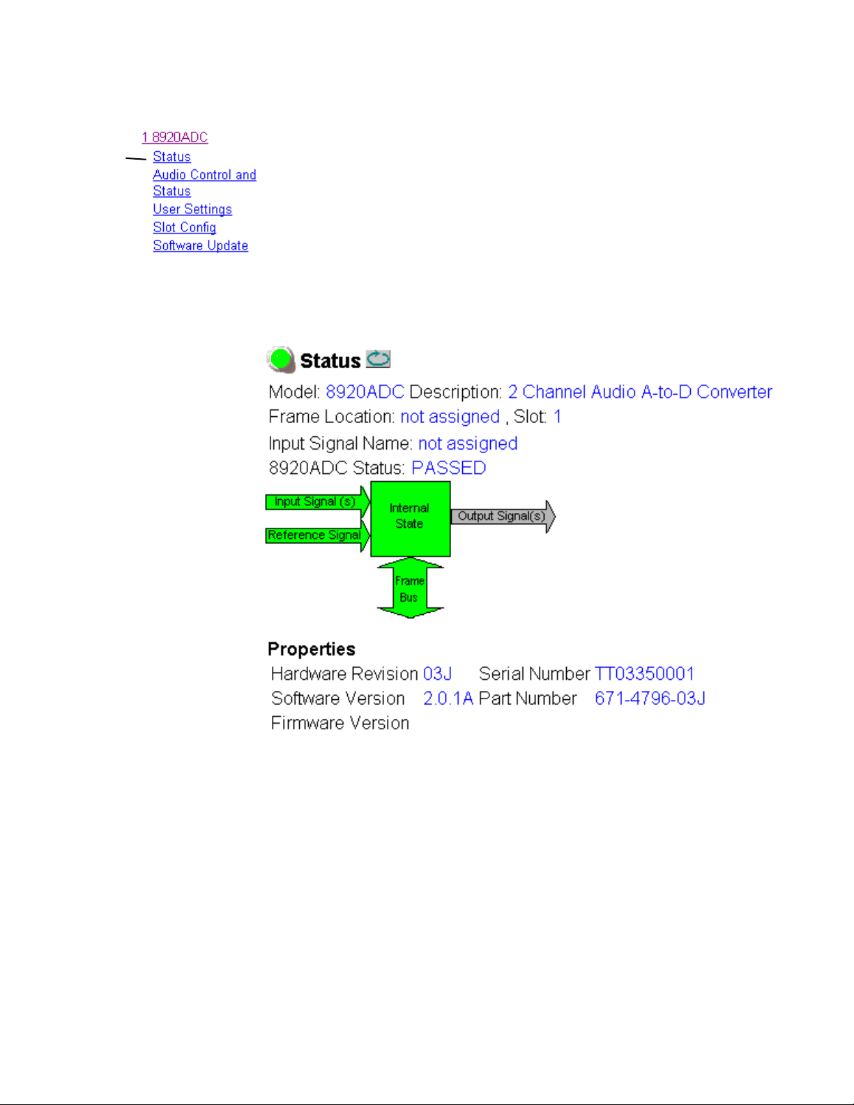
8920DAC Links and Web Pages
The 8900 GUI provides the following links and web pages for the 8920ADC
module (Figure 8):
• Status – reports input and reference signal status and module information (page 23),
•Audio Control and Status – select output format for module and adjust
the levels for video, composite sync and DC output, and video setup
amplitude (page 24),
•User Settings – select factory defaults and enable or disable status
reporting of audio inputs (page 26)
• Slot Config – provides a Locate Module function and Slot Memory and
SNMP reporting status information (page 27), and
• Software Update – provides information on software updating
(page 29).
Figure 8. 8920ADC Web Page Links
Refer to Table 6 on page 17 for a summary in table format of all parameters
and their ranges, and default values.
22 8920ADC Instruction Manual
Page 23
Status Web Page
Configuration
Use
this
link
The Status web page (Figure 9) shows the input signal status of the audio
input and the Reference Signal input. Color coding of the display indicated
the signal status. Audio input status monitoring can be disabled on the
User Settings webpage (page 26). If set to disabled, the Input Signal (s)
arrow will be gre yed out. Refer to Status Monitoring on page 32 for an
explanation of the color coding.
Information about the module, such as part number, serial number, hardware revision and software and firmware versions are given in a read-only
section at the bottom of the display.
Figure 9. 8920ADC Status Web Page (Monitor Audio Inputs Enabled)
8920ADC Instruction Manual 23
Page 24

Configuration
Use
this
link
Audio Control and Status Web Page
The Audio Control and Status web page (Figure 10 on page 25) provides
controls for setting the following audio parameters on the 8920ADC
module:
•Operational (output) mode, and
• Fine adjustment of left and right output channel levels.
The following audio status items are reported on this web page:
• Left and Right Ch > -20 dBFS – indicates whether the left and right
channel digital output levels are greater than -20 dBFS (True) or less
than -20 dBFS (False).
• Left and Right Ch > -0.5 dBFS Clip – indicates whether the digital
output clipping levels are greater than -0.5 dBFS (True) or less than -0.5
dBFS (False).
•Reference Signal – indicates whether the module is
reference signal is present and module is locked to it) or
Locked (valid AES in
Unlocked
(module does not detect a valid AES in reference signal).
Use the following controls to set the parameters for the 8920ADC:
•
Operational Modes – Set the operational mode pulldown for the desired
output of the module from the thirteen selections listed below in
Table 7 and shown in the web page in Figure 10 on page 25. After
making the selection, select the
Table 7. Audio Output Configuration Modes
Mode Name Mode Description
Default Factory default with no phase inversion, channel swapping or summing.
L/R Swap Swaps left and right channel outputs.
L/R Invert Both left and right channel outputs phase inverted.
L Invert Left channel output phase inverted.
R Invert Right channel output phase inverted.
R Mono (R to L/R) Right channel to both channel outputs.
L Mono (L to L/R) Left channel to both channel outputs.
L plus R to L/R Left plus right to both channel outputs.
L minus R to L/R Left minus right to both channel outputs
L plus R, L minus R Left plus right to left channel output and left minus right to right channel output.
(L plus R) Inv to L/R Left plus right to both channel outputs with both channel outputs phase inverted.
AES Silence AES silence on both left and right channel outputs.
1K@ -20dBFS Tone to both channel outputs.
Apply button to activate it.
24 8920ADC Instruction Manual
Page 25

Configuration
• Left and Right Channel Levels – fine gain adjustment of the module
output levels can be done with the
Coarse gain levels must first be set up using the on-board jumpers JP5
and JP6 as described in Remote Configuration and Monitoring on page 19.
Follow the procedures given there for adjusting the output levels using
the fine gain adjustments described below.
Left and Right Channel Level controls.
Adjust the fine gain in either
shown in Figure 10.) The single arrows increment the value by 1x and
the double arrow will increment the value by approximately 10x. These
controls will allow you ± 6.0 dB of fine adjustment range.
Note In Numeric mode only, values selected with the single or double arrow keys
will be enabled immediately. All other display entries, including typed in
values, require pressing Apply before the selection is enabled.
Figure 10. 8920ADC Audio Control and Status Display
Numeric or Sliders mode (Numeric mode
8920ADC Instruction Manual 25
Page 26

Configuration
User Settings Web Page
The User Settings web page (Figure 11) allows you to set the following
parameters:
Use
this
link
• Select the
tings (Operation output mode to default, all audio levels to 0 dB, and
Monitor Audio Input mode to disabled).
• Set Monitor Audio Inputs to enable or disable the status reporting of
the audio inputs. When set to disabled, the Input Signal(s) arrow on the
Status web page will be greyed out.
Figure 11. 8920ADC User Settings Web Page
Get Factory Defaults button to return the module to factory set-
26 8920ADC Instruction Manual
Page 27

Use
this
link
Slot Config Web Page
Use the Slot Config web page (Figure 12 on page 28) to perform the following functions on the 8920ADC module:
•
Locate Module – selecting the Flash radio button flashes the yellow
COMM and CONF LEDs on the front of the module so it can be located
in the frame.
•
Controls – the Controls status report will display either Normal or Remote
Override if a setting on the web pages is overriding that of the module
jumpers.
•
Slot Identification – You may identify the module by typing a specific
name in the
module and travels with the 8900NET module if it is moved to another
frame. Select
Configuration
Name field. The assigned name is stored on the 8900NET
Default to enter the factory default module name.
You may also enter a name in the
•
Slot Memory – the slot configuration for each media module is automati-
Input Signal Name field.
cally saved periodically (once an hour) to the 8900NET module in that
frame. You may also select the
Learn Module Config button at any time to
save the current configuration for this slot. The configuration is saved
on the 8900NET module. If the 8900NET module is removed or
powered down, the stored configurations are not saved.
When the
Restore upon Install box has been checked, the current configu-
ration saved to this slot is saved as slot memory. When the current
module is removed and another module of the same type is installed,
the configuration saved to the 8900NET module will be downloaded to
the new module. The box must be checked before the current module
with the saved configuration is removed.
•
Frame Heath Reporting – this function is not active with the latest version
of the 8900NET module that controls this page.
•
Hardware Switch Controls – a read-only status report of 8900NET module
switch settings for Module Status Reporting and Asynchronous Status
Reporting. These functions must be enabled for the following Slot
SNMP Trap Reports to function.
•
Slot SNMP Trap Reports – displayed only when the SNMP Agent software
has been installed on the 8900NET module. Slot SNMP traps can be
enabled only when the hardware switches for Module Fault reporting
and Asynchronous Status reporting are in enabled on the 8900NET
module (dipswitch S1 segment 5 and dipswitch S2 segment 1).
The enabled SNMP traps will be reported to any SNMP manager that
is identified as an SNMP Report Destination in 8900NET configuration.
Trap severity is read-only hard-coded information that is interpreted
and responded to by the SNMP Manager software configuration.
8920ADC Instruction Manual 27
Page 28

Configuration
Figure 12. 8920ADC Slot Config Web Page
28 8920ADC Instruction Manual
Page 29

Software Update Web Page
The Software Update page (Figure 13) is not used to update 8920ADC software. For instructions on updating to the latest software, refer first to the
8920ADC Release Notes that accompany the software update for complete
details.
Configuration
Use
this
link
Currently, the only recommended method of software updating is done
with a software kit (8900-FLOAD-CBL) that includes a CD-ROM with the
current software files and a serial cable assembly available from Grass
Valley.
Refer to the 8900-FLOAD-CBL Software Upgrade Instruction Manual in
PDF format on the CD-ROM for complete updating instructions and the
required software files for the module.
Figure 13. 8920ADC Software Update Web Page
8920ADC Instruction Manual 29
Page 30

Specifications
Specifications
Table 8. 8920ADC Specifications
Parameter Value
Analog Input
Number of inputs Balanced stereo pair
Connector type Terminal block
Input impedance > 20 kΩ differential
Input level range +12 to +28 dBu
Common mode rejection > 65 dB 50 Hz to 20 kHz
Differential DC 0.25 V maximum
Common mode input voltage 20 V maximum
AES Reference Input
Signal type AES3 ID (1992) transformer coupled
Number of inputs 1 Loop-through
Input return loss >15 dB (100 kHz-10 MHz)
Sampling rate 48 kHz
Maximum jitter < 200 ps RMS
Outputs
Number of outputs 4
Signal type SMPTE 276M, AES3 ID (1992)
Signal level +12 to +28 dBu input range adjustable to 0.0 dBFS
Output impedance 75 Ω
Connector type 75 Ω BNC
Coupling AC coupled
Performance (@ +28 dBU input and full scale output)
Sampling rate 48 kHz
Frequency response ± 0.05 dB relative to 1 kHz, 20 Hz to 20 kHz
Signal-to-noise ratio >102 dB unweighted, 20 Hz to 20 kHz
>105 dB “A” weighted, 20 Hz to 20 kHz
Interchannel crosstalk <-100 dB, 20 Hz - 20 kHz
Delay (input to output) 925 µS
Environmental
Frame temperature range See Gecko 8900 Frame specification
Operating humidity range 0 to 90% non-condensing
Non-operating temperature -10 to 70 degrees C
Mechanical
Frame type Gecko 8900 Series
Power Requirements
Supply voltage ±12 V
Power consumption < 4.2 Watts
30 8920ADC Instruction Manual
Page 31

Service
Service
The 8920ADC modules make extensive use of surface-mount technology
and programmed parts to achieve compact size and adherence to
demanding technical specifications. Circuit modules should not be serviced in the field.
If your module is not operating correctly, proceed as follows:
•Check frame and module power and signal present LEDs.
•Check for presence and quality of input signals.
•Verify that source equipment is operating correctly.
•Check cable connections.
•Check output connections for correct I/O mapping (correct input connector is used for the corresponding channel output).
Refer to Figure 4 for the location of PWR LED and Table 2 on page 11 for
proper LED indications.
If the module is still not operating correctly, replace it with a known good
spare and return the faulty module to a designated Grass Valley repair
depot. Call your Grass Valley representative for depot location.
Refer to the Contacting Grass Valley at the front of this document for the
Grass Valley Customer Support Information number.
8920ADC Instruction Manual 31
Page 32

Status Monitoring
Status Monitoring
This section provides a summary of status monitoring and reporting for a
Gecko 8900 Series system. It also summarizes what status items are
reported and how to enable/disable reporting of each item. There are a
number of ways to monitor status of modules, power supplies, fans and
other status items depending on the method of monitoring being used.
8900 Frame status will report the following items:
• Power supply health,
• Status of fans in the frame front cover,
•Temperature,
•Module health, and
• Frame bus status.
Module health status will report the following items:
• Internal module state (and state of submodule or options enabled)
including configuration errors (warning), internal faults, and normal
operation (Pass).
LEDs
• Signal input states including valid/present (pass), not present or
invalid (warning), not monitored, and not available (no signal inputs).
•Reference input states including locked/valid (pass), not
locked/invalid (warning), and not monitored.
• Signal output states with reporting functionality (reference output).
LEDs on modules in the frame and on the front of the 8900TF/TFN frames
indicate status of the frame and the installed power supplies, fans in the
front covers, and modules. (The 8900TX-V/A frames have no LED indicators on the front cover.)
When a red FAULT LED is lit on a frame front cover, the fault will also be
reported on the 8900NET or Frame Monitor module. The LEDs on the front
of these modules can then be read to determine the following fault conditions:
• Power Supply 1 and 2 health,
• Fan rotation status,
• Frame over-temperature condition,
• Frame Bus fault (8900NET only), and
•Module health bus.
32 8920ADC Instruction Manual
Page 33

Frame Alarm
Status Monitoring
In general, LED colors used on the frame and modules indicate:
•Green – normal operation, (Pass) or signal present, module locked.
•Red – On continuously = fault condition, flashing = configuration error.
•Yellow – On continuously = active condition (configuration mode or
communication), flashing in sequence = module locator function.
Status LEDs for this module are described in Indicator LEDs and Conditions
Indicated on page 11. LEDs for the 8900NET module are described in the
8900NET Network Interface Instruction Manual.
A Frame Alarm connection is available on pins 8 and 9 of the RS-232 connector on the rear of 8900 frame (Frame Monitor or 8900NET Network
Interface module required). This will report any of the status items enabled
with the 8900NET or Frame Monitor module configuration DIP switch.
Connection and use of the Frame Alarm is covered in detail in the 8900NET
Network Interface Instruction Manual.
Web Browser Interface
When the 8900NET module is installed in the frame, a web browser GUI
can indicate frame and module status on the following web pages:
• Frame Status web page – reports overall frame and module status in
graphical and text formats.
•Module Status web page – shows specific input and reference signal
status to the module along with enabled options and module versions.
•A Status LED icon on each web page to report communication status
for the frame slot and acts as a link to the Status web page where warnings and faults are displayed (8900NET version 3.0 or later).
In general, graphics and text colors used indicate the following:
•Green = Pass – signal or reference present, no problems detected.
•Red = Fault – fault condition.
•Yellow = Warning – signal is absent, has errors, or is mis-configured.
•grey = Not monitored (older 8900 module).
•White = Not present.
Status reporting for the frame is enabled or disabled with the configuration
DIP switches on the 8900NET module. Some module status reporting items
can also be enabled or disabled on individual configuration web pages.
8920ADC Instruction Manual 33
Page 34

Status Monitoring
SNMP Reporting
The Gecko 8900 Series system uses the Simple Network Monitoring Protocol (SNMP) internet standard for reporting status information to remote
monitoring stations. When SNMP Agent software is installed on the
8900NET module, enabled status reports are sent to an SNMP Manager
such as the Grass Valley’s NetCentral application.
There are both hardware and software report enable switches for each
report. Both must be enabled for the report to be sent. Software report
switches are set on the 8900NET Configuration web page for the Frame, the
8900NET module, and each module slot. Refer to the 8900NET Network
Interface Instruction Manual for installation instructions.
34 8920ADC Instruction Manual
Page 35

Functional Description
Differential
Input
Receivers
& Pad
Pad
+
Right In
Left In
AES Sync In
–
Pad
+
–
Functional Description
The 8920ADC Converts an analog audio stereo pair to a 48 KHz AES/EBU
signal. Refer to the block diagram in Figure 9 while reading the following
functional description.
Figure 9. 8920ADC Block Diagram
Control bus
from backplane
- 12 dB
- 8 dB
- 6 dB
- 12 dB
- 8 dB
- 6 dB
- 12 dB
- 12 dB
4-bit Rotary
CPU
(Controller)
- 15 dB- 9 dB
Audio
Stereo
- 15 dB- 9 dB
24-bit
ADC
Clocks
AES
Receiver
and PLL
Switch
FPGA
Routing and Control
Processor
Test
Tone
Option
Jumpers (4)
AES Out 1
AES Out 2
AES Out 3
AES Out 4
Level,
Clip,
Error,
PLL Lock,
Mode
LEDs
0595_01
Differential Input, Analog Gain and A/D Converters
The analog input is applied to a differential amplifier stage. This converts
the signal to single-ended and applies it to the coarse gain stage. Coarse
gain control pre-conditions the incoming signal before it is applied to the
A/D converters. For each channel, a six-position jumper sets the desired
coarse gain. This jumper controls the front-end pad of the unit in either a
-6 dB, -8 dB, or -12 dB mode and allows three 3 dB gain steps on the post
gain. This jumper allows input levels from +12 dBu to +28 dBu to be set to
0dBFS at the output.
The fine gain control is by two center-off toggle switches on the front of the
module. They provide a 6 dB range of fine gain adjustment in approximately 0.1 dB increments. The control takes approximately 6 to 10 seconds
to transition from minimum to maximum.
The signal is converted back to a differential signal and applied to the 24-bit
A/D converter, then to the Routing and Control FPGA (Field Programmable Gate Array).
8920ADC Instruction Manual 35
Page 36

Functional Description
Digital Reference Input
Routing and Control FPGA
The digital reference is applied via the loop-through input to the AES
receiver and phase-locked loop. This provides clock and data to the Control
and Routing FPGA and the A/D converters.
The signals from the A/D converters are applied to the Routing and
Control FPGA. The incoming signal processing and level is determined by
the setting of one of 16 possible mode commands from a four-bit rotary
encoder switch and four signals from the level toggle switches. After processing, the signals are embedded into an AES stream and applied to the
Output Drivers.
The Routing and Control section also drives the front panel LEDs and interfaces to the Controller section.
Controller
Power Supply
The Controller interfaces with the Routing and Control FPGA, the
EEPROM and the 8900 Frame Bus. The Controller also provides the FPGA
code that is downloaded to the FPGA during boot-up.
The Controller section handles local control and monitoring, as well as
remote control and monitoring via the frame bus (when an 8900NET
module is installed in the frame). Module settings are stored in the
EEPROM for power up recall.
Power is fed from ±12 V rails of the frame’s switching power supply. Each
stage of the module receives it’s own, separate, highly regulated and filtered power source. Two-stage regulation is used in the analog section of
the ADC to reduce switching noise.
36 8920ADC Instruction Manual
Page 37

Index
Numerics
20/24-bit DAC
remote indication
8900 frame
frame alarm
status reporting 32
8900-FLOAD-CBL option 29
8900NET module
required software version
8920ADC
features
functional description 35–36
specifications 30
7
24
33
A
Audio Control and Status web page 24
C
cabling 10
input 10
output 10
coarse level adjustment 14, 18, 25
COMM LED 11
CONF (configuring) LED 11, 18
configuration 16
factory default 11
jumpers 18
LEDs 18
local on-board 18
overview 13
Remote, GUI 19
summary table 17
switches 18
control panel
control summary table
overview 19
Controls status reporting 27
17
19
D
documentation online 2
E
enable SNMP 34
F
factory defaults
remote control
summary table 17
FAQ database 2
FAULT LED
description
troubleshooting 32
fine level adjustment
local on-board
remote 25
frame
cell locations
cooling capacity 8
module capacity 8
power capacity 8
Frame Status page 33
frequently asked questions 2
26
11
18
8
G
Get Factory Defaults button 26
graphical user interface (GUI) 22
Grass Valley web site 2
I
impedance 10
input
loopthrough
reference 10
specification 30
input signal name
10
8920ADC Instruction Manual 37
Page 38

Index
assigning 27
installation 8
L
left channel level
remote control
summary table 17
LEFT IN > -20 dBFS LED 12
LEFT IN CLIP LED 12
locate module 27
LOCK LED 12
25
M
maximum operating level 14
mode
output
module
block diagram
cells 9
install 9
placement 8
replacement 31
module health status 32
module name
assigning
Module Status page 33
monitor audio output control
remote control
summary table 17
16
35
27
26
output mode
rotary switch
outputs
configuration
connectors 10
level adjustments 19
local on-board 15
remote 25
specification 30
termination 10
overlay 10
16
16
P
power requirements 30
PWR LED 11
R
reference inputs 10
REM OVER (remote override) LED 12
remote control lockout
jumper
report enable switches 34
right channel level
remote control
summary table 17
RIGHT IN > -20 dBFS LED 12
RIGHT IN CLIP LED 12
rotary switch 16, 18
16, 18
25
S
N
Newton Control Panel
overview
summary table 17
19
O
online documentation 2
operational conditions
LED indications
operational mode
remote control
rotary switch 16
summary table 17
38 8920ADC Instruction Manual
11
24
Slot Config web page 27
slot memory 27
SNMP reporting
enabling
overview 34
software download from web 2
software update
8900-FLOAD-CBL
Software Update web page 29
status monitoring 32
Status web page 23
27
29
Page 39

T
termination 10
toggle switches 18
setting levels 14
troubleshooting 31
U
User Settings web page 26
W
web browser
overview
web site
documentation
FAQ database 2
Grass Valley 2
software download 2
20
2
Index
8920ADC Instruction Manual 39
Page 40

Index
40 8920ADC Instruction Manual
 Loading...